R Rolling bearings in paper machines · 2018-08-07 · 3 Foreword This latest version of the SKF®...
212
Rolling bearings in paper machines
Transcript of R Rolling bearings in paper machines · 2018-08-07 · 3 Foreword This latest version of the SKF®...

R
Rolling bearings in paper machines
Rolling bearings in paper m
achines

9
1 General requirements and recommendations
2 Forming section
3 Press section
4 Dryer section
5 Calenders
6 Reeler
7 Lubrication
8 Lubrication examples
9 Maintenance
1
2
3
4
5
6
7
8

Rolling bearings in paper machines
Handbook for the paper machine designers andoperators

3
ForewordThis latest version of the SKF® application,lubrication and maintenance handbook forbearings in paper machines has been developedwith the various specialists involved in theindustry. For the paper machine designer, itincludes the information required to select theright bearings and to design optimised arrange-ments for them. For the specialists working inthe paper mills, there are recommendations onhow to maximise bearing service life throughappropriate mounting and dismounting, maintenance and lubrication procedures.
The recommendations are based on experi-ence gained by SKF during decades of closecooperation with machinery manufacturers andpaper mills from all around the world. Workingtogether with the industry has also stronglyinfluenced SKF product development, leadingto the introduction of a large number of newproducts and variants. Many of these have beendeveloped specifically for the paper industryand all are based on the needs of the user.
General information about bearings is contained in the SKF General Catalogue and the SKF Interactive Engineering Catalogue while specific recommendations for papermachines are included in this handbook. Information from the General Catalogue is only included when necessary for the sake of clarity.

Contents
Made by SKF® stands for excellence. It symbolises our consistent endeavour to achieve total quality ineverything we do. For those who use our products.“Made by SKF” implies three main benefits.
Reliability – thanks to modern, efficient products, based on our worldwide application know-how, optim-ised materials, forward-looking designs and the most advanced production techniques.
Cost effectiveness – resulting from the favourable ratio between our product quality plus service facilities,and the purchase price of the product.
Market lead – which you can achieve by takingadvantage of our products and services. Increasedoperating time and reduced down-time, as well asimproved output and product quality are the key to a successful partnership.
1 General requirements and recommendations...... 9
Selection of bearing size ............................................ 10
Bearing types used in paper machines..................... 13
Housings and journals ................................................ 18
Oil flow resistance....................................................... 24
High-speed machines ................................................. 26
2 Forming section ...................................................... 29
Bearing arrangements ................................................ 32
3 Press section ........................................................... 39
Bearing arrangements ................................................ 43
4 Dryer section ........................................................... 51
Bearing arrangements ................................................ 55
5 Calenders................................................................. 69
Bearing arrangements ................................................ 72
6 Reeler ....................................................................... 77
Bearing arrangements ................................................ 78
4

5
7 Lubrication.............................................................. 83
Why lubricate?............................................................ 83
General notes on lubrication..................................... 86
Grease lubrication...................................................... 91
Oil lubrication ............................................................. 95
Cleanliness control .................................................... 98
8 Lubrication examples ............................................ 105
9 Maintenance........................................................... 181
Maintenance philosophies ........................................ 182
Services and products supplied by SKF .................. 184
Rebuild front side of drying and Yankee cylinders to a CARB® bearing arrangement ............ 185
Mounting and dismounting ....................................... 186
Condition monitoring ................................................. 193
Standstill precautions ................................................ 196
How to store spare bearings..................................... 197
How to avoid transport damage ............................... 199
Failure modes ............................................................. 200
How to avoid surface damage .................................. 207

The SKF Group – a worldwide corporation
6
SKF is an international industrial Groupoperating in some 130 countries andis world leader in bearings.
The company was founded in 1907following the invention of the self-align-ing ball bearing by Sven Wingquist and,after only a few years, SKF began toexpand all over the world.
Today, SKF has some 40 000 em-ployees and around 80 manufacturingfacilities spread throughout the world.An international sales network includesa large number of sales companiesand some 7 000 distributors and retailers. Worldwide availability of SKFproducts is supported by a compre-hensive technical advisory service.
The key to success has been a con-sistent emphasis on maintaining the highest quality of
SKF manufacturesball bearings, rollerbearings and plainbearings. The small-est are just a fewmillimetres (a frac-tion of an inch) indiameter, the largestseveral metres. SKFalso manufacturesbearing and oilseals which preventdirt from enteringand lubricant from leaking out. SKF’ssubsidiaries CR and RFT S.p.A. areamong the world’slargest producers of seals.
its products and services. Continuousinvestment in research and develop-ment has also played a vital role,resulting in many examples of epoch-making innovations.
The business of the Group consistsof bearings, seals, special steel and acomprehensive range of other high-tech industrial components. The ex-perience gained in these various fieldsprovides SKF with the essential know-ledge and expertise required in orderto provide the customers with themost advanced engineering productsand efficient service.

7
The SKF Group is the first major bearingmanufacturer to have been granted approvalaccording to ISO 14001, the internationalstandard for environmental managementsystems. The certificate is the most com-prehensive of its kind and covers more than60 SKF production units in 17 countries.
SKF has developed the Channel concept infactories all over the world. This drasticallyreduces the lead time from raw material toend product as well as work in progressand finished goods in stock. The conceptenables faster and smoother informationflow, eliminates bottlenecks and bypassesunnecessary steps in production. TheChannel team members have the know-ledge and commitment needed to share theresponsibility for fulfilling objectives in areassuch as quality, delivery time, productionflow etc.
The SKF Engineering & Research Centre is situated just outside Utrecht in TheNetherlands. In an area of 17 000 squaremetres (185 000 sq.ft) some 150 scientists,engineers and support staff are engaged inthe further improvement of bearing perform-ance. They are developing technologiesaimed at achieving better materials, betterdesigns, better lubricants and better seals – together leading to an even better under-standing of the operation of a bearing in itsapplication. This is also where the SKF LifeTheory was evolved, enabling the design of bearings which are even more compact and offer even longer operational life.

1 General requirements and recommendations
Selection of bearing size . . 10
Bearing types used inpaper machines . . . . . . . . . . 13
Housings and journals . . . . 18
Oil flow resistance . . . . . . . . 24
High-speed machines . . . . . 26

General requirementsand recommendations
9
A paper machine has a large number of rolls, all of which are equipped withmedium and large-size rolling bearings(➔ fig ). In a few applications, plainbearings are sometimes used.
The operating speeds of the differenttypes of modern paper machines areas follows:
1
1
1 General requirements and recommendations
12
31
4
5 67
8
7 9 10
11
613
12
16
14 15
Basic layout ofnewsprint and finepaper machine1. Wire roll2. Forward drive roll3. Forming roll
(suction roll)4. Suction couch roll5. Pick-up roll6. Spreader roll7. Felt roll8. Shoe press9. Drying cylinder10. Vacuum roll11. Guide roll
(wire roll)12 Deflection com-
pensating pressroll (soft calender)
13. Thermo roll (soft calender)
14. Reel drum15. Reel spool16. Paper web
1Fig
A modern paper machine can be more than 10 metres wide, 20 metres high and 200 metreslong. Generally they consist of a forming orwire section, a press section, a drying section, a coating section, a calender and a reeler. Largemachines incorporate as many as 1 500 bearings.Operating conditions for these bearings arevary greatly depending where they are installed.
Pulp drying machines 100–300 m/minBoard machines 400–800 m/minLiner machines 500–1 300 m/minFine paper machines 900–1 800 m/minNewsprint machines 1 000–2 000 m/minTissue machines 1 500–2 200 m/min

1,0 0,9 0,8 0,7 0,6 0,5 0,4 0,3 0,2 0,1 0L0L10
≈ 0,005
LL10
20
15
10
5
1
Selection of bearing sizeFatigue life – service lifeBy definition a bearing is consideredto have failed by fatigue as soon asflaking (spalling) occurs. Flaking can bedetected by using a vibration-sensitiveinstrument. If operation is continuedafter the first sign of flaking has beenrecorded, the flaked area will increasein size and the vibration level will rise.
SKF has gathered a lot of statisticsfrom endurance life testing of rollingbearings. The results of these tests are shown in diagram . The diagramshows that the fatigue life of one bearing can differ a greatly from thatof another bearing in a large configu-ration.
The length of time that a bearingcan be left in service after reaching itsdefined fatigue life is generally difficultto specify. Under laboratory conditions,it has been possible to run bearingsfor 0,2 to 7 times their basic rating life,after flaking has been detected.
The replacement of failed bearingsas soon as possible is always recom-mended, especially if they are in a crit-ical position, mounted with excessiveinterference fit, subjected to heatingthrough the journal etc. Apart from anincreasing vibration level in the bearing,there is always a risk of cracking theinner ring.
To the end-user of SKF bearings, the term bearing life means the timethat the bearings work satisfactorily inthe machine. SKF calls this the servicelife of the bearings. The service life ofpaper machine bearings is especiallyinteresting as these bearings are usually replaced for reasons otherthan fatigue.
L = Real bearing fatigue lifeL10 = Basic rating life according to
the ISO definition (the life that90 % of all bearings attain orexceed)
L0 = Minimum life exceeded by allbearings
1
10
1 General requirements and recommendationsSelection of bearing size
Paper machines differ in designaccording to the grade of paper that is to be produced. For example, whenit comes to the number of drying cylin-ders, board machines have the most,followed by liner and newsprint ma-chines. A great number of drying cylin-ders are needed in liner and boardmachines on account of the productthickness, and in newsprint machinesbecause of the very high paper speed.Tissue papers require less drying andtherefore the dryer section normallyconsists of only one large cylinder,called a Yankee cylinder. The webforming part also differs from machineto machine.
For modern newsprint paper ma-chines the steam temperature is around140 to 150 °C. For liner and boardmachines the maximum temperature isaround 190 to 200 °C. Sometimes themachines operate with super-heatedsteam, and then temperatures up to225 °C are common. Tissue machinesnormally have steam temperaturesbetween 150 and 200 °C.
How these temperatures influencebearing temperatures is shown in the Lubrication examples (➔ pages105–179).
Bearing life dispersion
Diagram
Survival probability

11
Recommended L10h and L10ah livesAs the service life is often shorter thanthe fatigue life, it is necessary to selectsomewhat “oversized” bearings. In thepapermaking industry, SKF has manyyears of experience selecting bearingsize using the L10h and L10ah bearinglife equations.
When calculating the life of papermachine bearings, SKF recommendsthat both the basic rating life L10h andthe adjusted rating life L10ah are takeninto consideration. The calculatedbearing lives L10h and L10ah shouldexceed 200 000 hours for dryer sectionbearings and 120 000 hours for bear-ings in other sections. In this way, theinfluence of possible insufficient lubri-cation on the calculated bearing life istaken into consideration, which is ofparticularly importance for the dryersection bearings (➔ pages 86–87).
The Technical Association of thePulp and Paper Industry in USA (TAPPI)requires the L10ah life to be calculated.Calculations for drying cylinders, forexample, shall include an a23 factorbetween 0,26 and 0,5. The calculatedL10ah life must be 100 000 hours ormore for all bearing positions.
Calculation of bearing lifeThe most common way to calculatethe bearing life is to use the equationsin the General Catalogue. The equa-tions to be used are
1 000 000 (C)p
L10h =60n P
and
L10ah = a23 L10h
whereL10h = basic rating life, operating
hoursn = rotational speed, r/minC = basic dynamic load rating, NP = equivalent dynamic bearing
load, Np = exponent of the life equation
p = 3 for ball bearings p = 10/3 for roller bearings
L10ah = adjusted rating life, operatinghours
a23 = combined factor for materialand lubrication
1
1 General requirements and recommendationsSelection of bearing size
Modern papermachine

There are advantages and disadvant-ages with these conventional methods.One advantage is that they comply withISO standards. These methods are alsoeasy to use because of the limitedamount of input data needed.
The main disadvantage is the limitedscope for performing an accurate cal-culation where all influential factors are taken into account. Housings andjournals, for example, are assumed tobe stiff and perfectly round.
Therefore, SKF has developedadvanced computer programs toenable in-depth analysis, including theinfluence of:
• internal design of the bearing• clearance reduction due to heat
generation in the bearing• clearance reduction due to external
heating• clearance reduction due to housing
or journal interference fit• axial preloading• errors of housing form• bearing temperature due to heat
generation in the bearing and external heating/cooling
This type of analysis is very useful forinvestigating bearing failures and alsowhen designing housings etc.
The SKF Life Method calculating L10aahThe SKF Life Method highlights the significant influence of cleanliness onthe fatigue life of bearings. Even thoughbearings in pulp and paper machineryrarely run until they are fatigued, clean-liness has an important influence onservice life.
The equation to be used is
L10aah = aSKF L10h
Values of aSKF for standard roller bear-ings are given as a function of ηc (Pu/P)in diagram , whereηc = adjustment factor for
contaminationPu = fatigue load limit, NP = equivalent dynamic
bearing load, NFor SKF spherical roller bearings ofExplorer quality, please refer to the SKFInteractive Engineering Catalogue, seealso page 15.
2
12
1 General requirements and recommendationsSelection of bearing size
More information is given in the SKF General Catalogue and the SKFInteractive Engineering Catalogue. Themethod can be used to evaluate thebenefits of improving cleanliness andalso to analyse the effects of higherlubricant viscosity.
SKF recommends the use of thismethod especially for downsizing andparametric studies. Contact SKF formore detailed information.
Factor aSKFfor radial rollerbearings
0,0050,010,02 0,050,05
0,1
0,1
0,2
0,2
0,5
0,5
1
1
2
2
5
10
20
50
5
aSKF
ηcPPu
κ =
42
0,8
0,5
0,15
0,1
0,2
0,6
0,4
0,3
1
2Diagram

13
1
1 General requirements and recommendationsBearing types used in paper machines
Bearing types used inpaper machinesPresent trends in the papermakingindustry indicate continuing increasesin output, necessitating larger machinesworking at higher speeds. Therefore,the bearings must be able to stand upto these increased loads and speeds,i.e. reach a long service life, while atthe same time keeping servicing andmaintenance requirements to a min-imum.
A high proportion of the bearingsused in papermaking machinery con-sist of spherical roller bearings of standard design. Their ability toaccommodate considerable radialloads in combination with axial loadsmake these bearings very suitable forsupporting the locating side (usuallythe drive side), of the various rolls andcylinders of paper machines. Sphericalroller bearings also permit misalign-ment between shaft and housing,which is especially important for papermachines where bearings are mountedin separate housings spaced far apart.
In many cases, spherical roller bear-ings can also be used successfully atthe non-locating side, (usually thefront side), of paper machines. How-ever, in most cases the ideal solutionis to combine a spherical roller bearing
2Fig
at the drive side with a CARB® toroidalroller bearing at the front side (➔ fig ).This bearing arrangement accommod-ates both misalignment and axial displacement internally and withoutfrictional resistance, with no possibilityof generating internal axial forces inthe bearing system (Fa = 0 for bothbearings).
If a CARB bearing is used it may be possible to downsize the bearingarrangements at both the drive andfront sides. Diagram , page 14,shows the life of different bearing systems. The coefficient of friction µfor steel against cast iron is 0,15–0,20for new housings of good quality. Forused housings the coefficient can beconsiderably higher. In the example µ = 0,15 is used.
3
2
The standard solution – SKFspherical rollerbearing on thedrive side and aCARB bearing onthe front side

1
00 0,05 0,1 0,15 0,2 0,25 0,3 0,35 0,4*
1,20
0,37
0,70
23148 23148
C 3148 23148
C 3144 23144
14
SKF spherical roller bearings of CC, C and EC designsThese bearings have symmetrical rollers, a flangeless inner ring and apressed steel cage for each roller row(➔ fig ). The guide ring is centred on the inner ring. EC design bearingsincorporate reinforced roller sets foradded load carrying capacity. Thebearings of the CC design have beenoptimised to promote roller guidancewhich reduces friction.
3
1 General requirements and recommendationsBearing types used in paper machines
4Fig
SKF spherical roller bearings of CAC, ECAC, CA and ECAdesignsThese designs are used for the largesizes of SKF spherical roller bearings(➔ fig ). The rollers are symmetricaland the inner ring has retaining flanges.The guide ring is centred on the innerring between the two rows of rollersand the cage is a one-piece, doublepronged machined steel or brasscage. The CAC and ECAC designsincorporate the CC design and theECAC and ECA designs have rein-forced roller sets for increased loadcarrying capacity.
4
3FigSKF sphericalroller bearing ofCC, C and ECdesigns
SKF sphericalroller bearing ofCAC, ECAC, CAand ECA designs
Rel
ativ
e L 1
0lif
e fo
r b
earin
g sy
stem
Friction coefficient µ
3Diagram
Relative life of different bearingsystems

15
1
1 General requirements and recommendationsBearing types used in paper machines
7Fig5FigSKF spherical roller bearing of E design
CARB toroidalroller bearing
SKF spherical roller bearings of E designThese bearings have symmetricalrollers, a flangeless inner ring, and aguide ring centred on the hardenedcages (➔ fig ). The E design bear-ings incorporate all the advantages ofthe well-proven SKF CC bearings aswell as additional refinements such ashigher load carrying capacity.
SKF ExplorerThe new Explorer bearings are the latest generation from SKF.
Developments in steel production,new heat treatment procedures and a new manufacturing process are the factors behind the new bearing. Themain advantages with the bearing arelonger life for existing machines andthe possibility for downsizing on newmachines. To enable users to predictbearing life more accurately SKF hasintroduced increased basic dynamic
5
load ratings and an additional factor tobe considered when calculating L10aahlife using the SKF Life Method.
The Explorer bearings retain thedesignations of the earlier standardbearings e.g. 22218 E or 23152 CC/W33.However, each bearing and box ismarked with the name Explorer (➔ fig ).
More information about Explorerbearings and the present range can beobtained from your local SKF company.
CARB®
The best solution for most rolls andcylinders is to combine a sphericalroller bearing on the drive side with aCARB toroidal roller bearing on thefront side as CARB is the ideal non-locating bearing (➔ fig ). 7
6
Explorer bearings
6Fig

16
1 General requirements and recommendationsBearing types used in paper machines
Like a spherical roller bearing, theCARB bearing can accommodate misalignment and heavy radial loads,but is also able to take axial displace-ment without frictional resistance, like acylindrical roller bearing. This is whatmakes CARB bearing the ideal non-locating solution for most papermachine applications. The CARB bear-ing has the same friction as a sphericalroller bearing and should therefore belubricated in the same way. However,CARB bearings must always be lubric-ated from the side since it has nolubrication groove in the outer ring.
DesignationsThe most common supplementary des-ignations for spherical roller bearingsand CARB toroidal roller bearings areshown in table . The table alsoshows where in the machine the bearings are used.
Table gives a larger number ofsupplementary designations that canbe seen in a paper machine.
Doctor bearingSpecially designed multi-row radialball bearings are used for doctors,allowing both the axial oscillation ofthe doctor as well as rotating move-ment (➔ fig ). Specially designedplain bearings can also be used. The
8
2
1
8Fig SKF doctor bearing
Common supple-mentary designa-tions for SKFspherical rollerbearings andCARB bearings
Features Require- Rollsment Forming section Press section Dryer section
CalendersForming Suction Wire Suction Press Felt Dryers Yankees Felt Thermo Others
Clearance std X X X
C3 (X) X X X X X
C4 X X X
Running std X X X Xaccuracy
C08 X X X X X X
VQ424 X X X
Heat std X X X X X X X Xtreatment
HA3 X X X
Special L5DA (X) (X) (X)features
1Table
rotating movement is necessary whenthe doctor is turned to a rest positionduring maintenance or changing theblade. In addition to this degree ofmovement, the bearing is able to takeshaft misalignment. This misalignmentis accommodated either by a radiuson the outer diameter which adjust themisalignment between housing andbearing or, for another bearing execu-tion, in the sphere between the twomating parts of the bearing outer ring.

17
1
1 General requirements and recommendationsBearing types used in paper machines
C Spherical roller bearing with symmetrical rollers and floating central guide ring
CA Spherical roller bearing of C design but with two integral inner ring flanges and machined cage
CC Spherical roller bearing of C design but with improved roller guidance and reduced friction
CAC Spherical roller bearing of CA design but with improved roller guidance and reduced friction
C2 Radial internal clearance less than Normal
C3 Radial internal clearance greater than Normal
C4 Radial internal clearance greater than C3
C5 Radial internal clearance greater than C4
C08 Extra reduced tolerance for running accuracy (P5) of inner ring and outer ring of assembled bearing
C083 C08 + C3
C084 C08 + C4
E Standard spherical roller bearing with modified internal design, increased carrying capacity and W33 features
F Machined cage of steel or special cast iron
HA1 Case-hardened inner and outer rings
HA3 Case-hardened inner ring
J Pressed steel cage
K Tapered bore, taper 1:12 on diameter
K30 Tapered bore, taper 1:30 on diameter
M Machined brass cage
S1 Bearing rings dimensionally stabilised for operating temperatures up to +200 °C (standard for SKF spherical roller bearings and CARB bearings)
VA405 Specially heat treated pressed steel cages centred on the guide ring, outer ring centred guide ring and radial internal clearance C4
L5DA No Wear™ (DLC coated rollers)
VQ424 Spherical roller bearing with running accuracy better than P5 (better than C08) and reduced width tolerance; additionally the bearing is according to W4 and W58 specifications and has a serial number
W4 Eccentricity high-point location marked on inner ring
W20 Three lubrication holes in outer ring
W26 Six lubrication holes in inner ring
W31 Bearing inspected to certain quality control requirements
W33 Lubrication groove and three holes in outer ring.
W58 Eccentricity high point location marked on outer ring
W77 Bearing with W33 holes plugged
W503 W33 + W4
W506 W31 + W33
W507 W4 + W31 + W33
W509 W26 + W31 + W33
W513 W26 + W33
W529 W33 + W58Supplementarydesignations usedfor bearings inpaper machines
2Table
Other bearing typesOther bearing types can also be seenin paper machines, e.g. cylindricalroller bearings in drying cylinder ap-plications, taper roller bearings in feltroll applications, deep groove ball bear-ings and self-aligning ball bearings inspreader rolls, and plain bearings incalender applications.

18
1 General requirements and recommendationsHousings and journals
Housings and journalsDue care must be given to the designof bearing housings and journals. Forexample, provision must be made foraxial movement on the non-locatingside. The space available for axialmovement has to be greater than thethermal expansion of the roll.
The housings and journals shouldbe strong enough to prevent excessivedeformation under operating condi-tions. Additionally, the housings shouldfit properly into the frame of the papermachine and permit easy mounting,dismounting, and inspection of thebearings. In some positions the hous-ings must also allow for the changingof wires and felts.
SKF has a range of special housingsfor felt rolls, drying cylinders andYankee cylinders, where all importantfunctional aspects have been takeninto consideration.
HousingsHistorically paper machines have been equipped with specially designedbearing housings. The manufacturerhas designed a special housing formore or less every individual machinewhich is costly in terms of patternequipment and design time. Speciallymade housings have also been very
9Fig 10Fig
difficult to find when a replacementhas been required at the paper mill.
SKF stepped into the lead positionin the early 1990’s by introducing astandard range of bearing housings forfelt rolls in the dryer section, dryingcylinders and Yankee cylinders. Allhousings are designed for high flowcirculating oil lubrication, have mainten-ance-free sealing arrangements andare prepared with connections forcondition monitoring.
Felt roll housings, dryer sectionFelt roll housings are available in thefollowing basic executions:
• Drive side: spherical roller bearingwith located outer ring (➔ fig )
• Front side: CARB bearing with located outer ring.
• Front side: spherical roller bearingwith non-located outer ring
SKF recommends the use of a sphericalroller bearing at the drive side and aCARB bearing at the front side.
Drying cylinder housingsDrying cylinder housings are availablein the following basic executions:
9
SKF felt roll housing
SKF drying cylinder housing

19
1
1 General requirements and recommendationsHousings and journals
• Drive side: spherical roller bearingwith located outer ring
• Front side: CARB bearing withlocated outer ring (➔ fig ).
• Front side: spherical roller bearingwith non-located outer ring
• Front side: spherical roller bearingwith located outer ring in housing onrockers
SKF recommends the use of a spher-ical roller bearing at the drive side and a CARB bearing at the front side.
10
11Fig
SKF Yankee cylinder rockerhousing
CARB bearings:Axial displacementdepends on radialclearance. Rollersmay protrude fromthe ring racewayat axial displace-ments above 20 %of the bearingwidth
–20 –10 0 10 20
0,4
0,2
0,1
–0,1
0
0,5
0,3
4Diagram
Radial clearance, % of bearing width
Axial displacement, % of bearing width
Yankee cylinder housingYankee cylinder housings are availablein the following basic executions:
• Drive side: spherical roller bearingwith located outer ring
• Front side: CARB bearing with located outer ring
• Front side: spherical roller bearingwith non-located outer ring
• Front side: spherical roller bearingwith located outer ring in housing onrockers
• Front side: spherical roller bearingwith located outer ring in housing onrockers with two support rockers (➔ fig )
SKF recommends the use of a sphericalroller bearing at the drive side and aCARB bearing at the front side.
Axial displacement for CARB bearingsThe relation between radial clearanceand axial displacement from a centralposition is shown in diagram . Thebearing may be further displaced with-out life reduction, into the dark bluearea. In this area friction increases byup to 50 %.
Axial displacement and radial clear-ance are given in relation to bearingwidth (B). This makes the diagramvalid for all CARB bearings.
Example: Bearing C 3044/HA3C4 withbearing width B = 90 mm.
4
11

Assuming that the operational radialclearance during start-up is 0,1 mm.That is 0,11 % of the bearing width.
Diagram , page 19, then shows(dotted line) that the bearing can beaxially displaced up to 11 % of bearingwidth, which is 0,11 × 90 = 9,9 mmfrom the centre.
During start-up, a typical operationalradial clearance at moderate steamtemperature and without journal insu-lation can be 0,1 % of the bearingwidth. This corresponds to a possibleaxial displacement from the centre of10 % of the bearing width.
Housing sealsA very important factor for the reliablefunctioning of bearings in papermachines is efficient sealing of thebearing arrangements. It is importantthat sealing arrangements adequatelyprotect the bearings from contamina-tion and also prevent the lubricantfrom escaping and running down themachine. A rolling bearing contamin-ated by water and/or solid particleswill become unserviceable long beforeits calculated life has been attained.
When designing seals, considerationmust be given to the environment ofeach specific bearing arrangement. Thebearing arrangements may be subject-ed to flowing water, condensation, dryconditions, or a high ambient temper-ature, depending on where in themachine they are positioned. Theseals of the housings on the non-locat-ing side must allow the required axial
4
20
1 General requirements and recommendationsHousings and journals
12Fig 13Fig 14Fig
Figs 12–14Sealing arrange-ments
movement. The basic design of theseal depends upon whether the bear-ings are lubricated by grease or oil.The application drawings in this hand-book show some examples of basicdesigns of bearing arrangements.
Different types of sealing arrange-ments are shown in the lubricationexamples. The need for efficient sealsis greatest in the wet section wheremost of the bearing arrangements aresubjected to very wet conditions.Experience shows that a well-greasedmulti-stage labyrinth seal, whether itbe axial or radial, affords good protec-tion of the bearings in the wet sectionespecially when it is reinforced by asplash guard (➔ fig ). If the bear-ings are oil lubricated, the sealingarrangements have to be of differentdesign. Fig shows an efficient sealfor oil lubricated press roll bearings.The seal must prevent water fromentering the bearing housing, evenduring hosing down, which is oftencarried out with water at high pressure.
In the dryer section of the machinethe bearing housings are exposed tomoisture in the form of condensationor leaks from steam nozzles etc. Smallsoft fibres may enter the housings too.Nevertheless, simpler seals may be usedfor the housings in the dryer section.However, if problems occur more effi-cient seals have to be applied. Figshows a proposal of how to improvethe seals of dryer section housings.
SKF can provide a full range ofgarter CR seals and V-rings.
14
13
12

21
1
d
h
l
15Fig
((2,5 + 0,2 × 2) × 42 × 103 + 3 × 220 × 3 000 × 4))1/4d = 2,2 = 20,8 mm
1 000
Oil outlet definition
whered = minimum bore of outlet pipe, mmn = number of 90° bendsQ = oil flow, l/minν = kinematic viscosity of oil at
lowest operating temperature (mostly at start-up), mm2/s
l = pipe length, mmh = oil level difference, mm
The equation is valid when the outletfrom the housing has no restrictions.Practical experience shows that if thereare restrictions close to the outlet, e.g.walls in bearing housings, the resist-ance to the inflow increases consider-ably. The calculated diameter d shouldthen be increased by 50 %.
Example
A drying cylinder bearing housing hasan outlet pipe with a length of 3 000mm to the first connecting main pipe.The oil level difference to this connec-tion is 1 000 mm and there are twobends. When starting up the machinethe oil viscosity can be 220 mm2/s ifthe temperature is around 40 °C.Select minimum bore diameter for the outlet pipe to avoid flooding whenthe circulating oil flow is 4 l/min.
With a restricted oil inflow the recom-mended minimum outlet pipe borediameter is
d = 1,5 × 20,8 = 31,2 mm
Select a pipe with a bore diameter larger than 32 mm!
Dimensioning of outlets in bearing housingsMany bearing positions in modernpaper machines are lubricated by cir-culating oil. For many years SKF hasrecommended larger oil flows thanthose normally used in older machines.One problem with older machines isdraining increased circulating oil flowthrough small dimensions oil outlets.Old machines without a heating sys-tem in the oil tank have great difficultystarting after a lengthy standstill. Theproblem is high oil viscosity due to lowoil temperature.
It is difficult to accurately calculatethe required outlet diameter becausemany variables influence oil drainage,e.g. oil level difference, length and dia-meter of the pipe, number of bends,and oil viscosity. Generally the outletdiameters are selected from experienceor by rule of thumb. Fig shows asketch of an outlet pipe with the relevant dimensions indicated.
An approximate calculation of therequired minimum outlet diameter canbe performed as follows
15
1 General requirements and recommendationsHousings and journals
((2,5 + 0,2 n) Q2 × 103 + 3 ν l Q))1/4
d = 2,2h

Tolerances
GeneralFrom a bearing function point of view,the main aspects of the housing andjournal design in paper machines arethe form and dimensional tolerances.
The accuracy of cylindrical bearingseatings on shafts and in housing boresshould correspond to the accuracy of the bearings used. In the following,guideline-values for the dimensional,form and running accuracies are givenand these should be adhered to whenmachining the seatings and abutments.
Dimensional tolerancesFor bearings made to normal toler-ances, the dimensional accuracy ofthe cylindrical seatings on the shaftshould be at least to grade 6, and inthe housing to at least grade 7. Whereadapter or withdrawal sleeves areused on cylindrical shafts, grade 9 (h9)can be permitted.
Tolerances for cylindrical formSince cylindricity is very difficult tomeasure, circularity and straightnessinstead are measured. The circularityand straightness tolerances as defined in ISO 1101-1983 should be one to twoIT grades better than the prescribeddimensional tolerance, depending on
16
22
1 General requirements and recommendationsHousings and journals
Definition of tapered journaltolerances
Fig
Circularity:In each radial plane alongthe tapered surface of theshaft the tolerance zone islimited by two concentriccircles a distance t apart
Straightness:In each axial plane throughthe tapered surface of theshaft the tolerance zone forthe generatrices is limitedby two parallel lines a distance t apart
IT5/2
IT5/2
1k
IT7B
±
1,6
2
∅ d
js9
t
t
*)
**)
**)
*) The tolerance is based on the bearing width B**) The tolerance is based on the diameter d
requirements. For example, if a bearingseating on a shaft has been machinedto tolerance m6, then the accuracy ofcircularity and straightness form shouldbe to IT5/2 or IT4/2. Note that the tolerances shown here are only half ofthe tolerance grades. This is becausethe total tolerance grade is valid forthe diameter and the definition is theradial deviation.
Two IT grades better than the pre-scribed dimensional tolerance is recom-mended when particularly stringentrunning accuracy requirements arestipulated, e.g. when bearings withextra close running accuracy toleranceC08 or VQ424 are used.
When bearings are to be mountedon adapter or withdrawal sleeves, thecircularity and straightness of the sleeveseatings should be IT5/2.
Tolerances for abutmentsAbutments for bearing rings shouldhave a total axial runout tolerance asdefined in ISO 1101-1983 which isbetter by at least one IT grade than thediameter tolerance of the associatedcylindrical seating. The axial runout ofthe abutments corresponds to the re-quired axial runout of the mounted innerring. The latter runout requirement ap-plies even when the bearing is mountedon a tapered journal without abutment.

23
1
Tolerances for tapered journal seatingsWhen the bearing is mounted directlyon a tapered journal seating, the seat-ing diameter tolerance is permitted tobe wider than in the case of cylindricalseatings. Fig shows a grade 9 dia-meter tolerance, while the form toler-ance stipulations are the same as forcylindrical journal seatings.
When establishing tolerances fortapered journal seatings for sphericalroller bearings different systems havebeen applied in Europe and the USA.
The European system was based onthe permissible angle deviation for thejournal taper being on the plus side ofthe nominal value, i.e. following thepractice applied to bearings. Moreover,the tolerance value was related to thenominal diameter of the journal.
In the USA the corresponding per-missible deviation was located on theminus side instead and the value wascoupled to the nominal width of thebearing.
These divergent methods have naturally led to practical difficulties.Consequently, a common SKF recom-mendation was agreed upon in 1986and this recommendation conformswell with the ISO tolerance tables.
The main points of the uniform SKFrecommendations for tapered journalsfor spherical roller bearings, also validfor CARB bearings, are as follows
� The permissible taper deviation formachining the taper seatings is a ± tolerance in accordance with IT7/2based on the bearing width. The per-missible deviation per mm is deter-mined by dividing the IT7/2 value inmm by the bearing width (➔ fig ).See also example on page 24.
� The straightness tolerance is IT5/2and is defined in accordance withfig .
� The radial deviation from circularity,defined in accordance with fig ,is to comply with IT5/2. When par-ticularly stringent running accuracyrequirements are stipulated, e.g.when spherical roller bearings withextra reduced running accuracy tolerance C08 or VQ424 are used,IT4/2 is to apply instead.
16
16
16
16
1 General requirements and recommendationsHousings and journals
Gauging the taper deviationThe best way to check that the taper iswithin the recommended tolerances isto measure with dial gauges. A morepractical method (but less accurate) is to use ring gauges or special tapergauges. Tapered seatings up to around150 mm in diameter are generallychecked with ring gauges, and thoseabove this size with special tapergauges. When indelible ink is used the area in contact should be at least90 %.
The gauge recommended by SKF inEurope can be seen in fig . Thegauge can be supplied by MicronwerkGmbH in Aschaffenburg, Germany. Thetaper deviation and the diameter of theseating in relation to a reference sur-face can be measured with this gauge.The tolerance M1 – M is calculated bymeans of the equation
( IT7 G )M1 – M = ± ×2 B
whereG = distance between the points of
measurement, mmB = bearing width, mm
17
M M1
G
17Fig
Gauge for taperedjournal, Europeandesign

Oil flow resistanceNormally, oil flow resistance in a bearingis insignificant. Sometimes, however,the question arises as to what pressureis needed to force oil with a certainviscosity through the duct formed bythe W33 lubrication groove and thehousing into the interior of the bearing.
The oil pressure required to over-come the oil flow resistance of the ductcan be calculated with the followingequation
Q D ν∆p =6 132 dh
4
where∆p= required oil pressure, MPaQ = oil flow, l/minD = bearing outside diameter, mmν = kinematic viscosity of oil at
lowest operating temperature(mostly at start-up), mm2/s
dh = hydraulic diameter, mm
The hydraulic diameter dh is a calcu-lated value describing a virtual dia-meter which is equivalent to thegroove cross section.
The calculation takes into consid-eration the resistance of the duct only.The length of the holes is very short,compared with the length of the duct,and therefore the resistance of theholes has been ignored.
The hydraulic diameter of the ductformed with different sizes of groove aswell as the groove dimensions can beobtained from table . The groovenumbers used for different sphericalroller bearings are also listed in table .
When the required oil pressure isconsidered to be too high, and to en-sure oil supply into the non-locatingbearings, an extra groove can be turnedin the bearing housing. The hydraulicdiameter for the enlarged duct can becalculated from
4 Adh =Oa
wheredh = hydraulic diameter, mmA = enlarged duct area, mm2
Oa = circumference of enlarged duct area, mm
3
3
24
1 General requirements and recommendationsHousing and journals/Oil flow resistance
18Fig
The gauge supplied by SKF in NorthAmerica can be seen in fig . It iscalled the sine bar gauge and thetaper deviation can be measured withthis tool.
Example: Spherical roller bearing23152 CCK/HA3C4W33 (bearingwidth 144 mm, IT7/2 for 144 mm is0,020 mm). The taper is to be meas-ured using our recommended gauge infig , page 23. If a gauge with 80 mmdistance between the measuring points(G) is used the taper deviation (M1 – M)is allowed to be
80±0,020 × = ±0,011 mm144
Support surface for housing baseIt is recommended that the supportsurface for the housing is finished toRa ≤ 12,5 µm. The flatness (planicity)tolerance should be to IT7 on thelength of the support surface.
17
18
SKF gauge fortapered journal,American design

Example
What oil pressure is needed to pump an oil flow of 5 l/min through the duct formed by the W33 grooveand the housing, into the bearing23052 CCK/C4W33? The maximumkinematic viscosity of the oil is 220 mm2/s.
The table shows that the groovenumber is 5, and thus dh = 5,18 mm.
5 × 400 × 220∆p = = 0,1 MPa6 132 × 5,184
By turning a 25 mm wide and 6 mmdeep groove in the housing seating theenlarged duct area will be (➔ fig )
and the circumference
19
25
1
Groove Groove dimension Hydraulic diameterNo. b h d1 dh
– mm mm
1 5,5 1,2 3,0 1,722 8,3 1,8 4,6 2,593 11,1 2,4 6,0 3,454 13,9 3,0 7,5 4,325 16,7 3,6 9,0 5,186 22,3 4,8 12,0 6,92
Bearing size1) GrooveSeries No.239 230 240 231 241 222 232 223over incl. over incl. over incl. over incl. over incl. over incl. over incl. over incl.
32 38 20 24 22 30 19 20 20 26 07 18 17 18 08 11 138 52 24 30 30 38 20 28 26 34 18 22 18 26 11 17 252 72 30 34 38 56 28 30 34 48 22 28 26 30 17 20 3
72 80 34 48 56 64 30 38 48 60 28 32 30 36 20 24 480 96 48 64 64 76 38 60 60 76 32 44 36 44 24 34 596 64 76 60 76 44 44 34 61) The figures in the table represent the last two figures of the designation; thus, bearing 23024 has groove No.1
3Table
b45°
d1
h
1 General requirements and recommendationsOil flow resistance
Groove sizes anddimensions andhydraulic diameterfor spherical rollerbearings
Example: dimensions ofenlarged area
25
16,7
3,6
6
3,6
19FigA = 25 × 6 + 3,6 (16,7 − 2 × 3,6) + 3,62 = 197,2 mm2
The hydraulic diameter thus becomes
4 × 197,2dh = = 12,14 mm65
and the required pump pressure
5 × 400 × 220∆p = = 0,0033 MPa6 132 × 12,144
The required pump pressure without a groove is 0,1 MPa. By turning agroove 25 × 6 mm in the housing seating a considerable reduction, to0,0033 MPa, is obtained.
2 × 3,6Oa = 25 + 2 × 6 + 25 − 2 × 3,6 + = 65 mmcos 45

High speed machinesThe operating speed of paper machineshas increased significantly over theyears and is expected to increaseeven more in the future.
Increased running accuracyWith production speeds higher than900 m/min there is an increased de-mand for bearings with extra-reducedtolerances for running accuracy. Themain reasons for these are to keephigh paper quality and to avoid feltwear as well as paper tears. Theseaims can be achieved by using C08 orVQ424 bearings to obtain low vibra-tion levels and a constant nip pres-sure. Press rolls, calender rolls andsuction rolls are examples of high-speed applications where these high-precision bearings are often used.
C08 means that dimensional runoutof the inner and outer rings correspondto ISO tolerance class P5.
VQ424 means that the bearing has aradial runout at least 20 % better thanP5 (C08) and reduced width tolerance.Additionally the bearing is accordingto W4 and W58 specifications, carryinga serial number. VQ424 and C08 bear-ings are an advantage in all rolls thatform a nip. VQ424 and C08 bearingsare also an advantage when regrindingthe rolls. By using such bearings lesstime is needed and higher accuracy isachieved.
As a rule of thumb, C08 or VQ424bearings should be used if the speedis equal to or exceeds 80 % of the oilspeed rating in the General Catalogueand the roll forms a nip with another roll.
Increased running accuracy of thebearing is not the only way to reducevibrations in paper machines. Anotherway is to decrease the runout of thejournal, see recommendations onpages 22–24.
Bearings mounted on adapter orwithdrawal sleeves are therefore mainlyseen in old machines.
The use of a spherical roller bearingas the locating bearing in combinationwith a CARB bearing as the non-locat-ing bearing has often resulted in lessvibration compared to the traditionalsolution using two spherical roller bearings.
26
1 General requirements and recommendationsHigh speed machines
NoWear™ bearingsOne way to improve the performanceof a bearing is to provide a beneficialcontact condition in cases where suffi-cient lubrication is difficult to obtain.Surface engineering to obtain a lowcoefficient of friction is a means ofachieving this. A commonly usedmethod in industry is surface coating.For a coating to work effectively in abearing it has to meet a set of require-ments such as hardness, ductility andfatigue resistance, in order to stay onthe surface during operation. The lowfriction ceramic coating in NoWearbearings from SKF is specially devel-oped for rolling bearings.
NoWear bearings provide long termlow friction and low wear properties byhaving a surface layer with a hardnessof 1 200 HV. The coefficient of frictionbetween coated rollers and steel isroughly one third of the friction be-tween two steel components. NoWearbearings prevent wear and smearing inbearings which operate at heavy loadas well as bearings which operate atradial loads less than the recommenda-tions in the General Catalogue (0,02 Cfor spherical roller bearings and CARBbearings).
In fast machines with large andheavy bearings which may operate atradial loads less than the recommenda-tions in the General Catalogue, SKFrecommends NoWear bearings withcoated rollers (L5DA). One example of such an application can be theupper thermo roll in soft calenders.
Speed rating – coolingSometimes the speed rating in theSKF General Catalogue is mistakenlytaken to be the maximum operatingspeed for the bearing. This is not thecase. By definition the speed rating is based on a certain temperature increase under specific operating conditions.

27
1
1 General requirements and recommendationsHigh speed machines
High speed machine
All bearings can be run at higherspeeds if satisfactory lubrication isobtained by cooling with circulatingoil. For example, suction and press roll bearings sometimes run at speedstwice the speed ratings in the GeneralCatalogue.
However, when bearings are run atvery high speeds additional aspects of internal radial bearing clearanceand lubrication have to be considered,especially for large-size bearings. Seepress section recommendations onlubrication and bearing type, pages45–46.

2 Forming section
Bearing arrangements . . . . 32

Forming section
29
2
2 Forming section
The forming section is the first part of the papermachine. The stock (pulp) contains around 99 %water at this stage. By the end of the formingsection the water content has to be about 80 %to make the paper web self-supporting as itmoves on to the press section. Depending onthe design of the forming section, modern papermachines can be grouped under the headingsFourdrinier machines or twin wire machines.
13
412
1110 987
6
5
43
2
1
1Fig
Fourdrinier machineThe Fourdrinier machine is the original,and still most widely used, formationunit. It can be used for virtually all types of paper and for machine speedsup to 900 m/min. Fig shows thewire part of such a machine.
Some wire parts are equipped witha dandy roll to flatten the top surface
1
of the sheet, giving it a smoother andcloser finish, and to make watermarksin fine papers.
At the end of the wire part there is asuction couch roll that finally reducesthe water content to 80 % to makethe web self-supporting. The suctioncouch roll is equipped with a drive sys-tem and drives the whole wire part.
Wire part of Fourdriniermachine1. Headbox2. Breast roll3. Table roll4. Suction box5. Dandy roll6. Suction couch roll7. Forward drive roll8. Wire roll9. Wire stretch roll10. Wire guide roll11. Wire12. Suction pickup
roll13. Paper web

Blade former In a blade former the dewatering zonecan be curved (➔ fig ). The curveddewatering zone is followed by suc-tion rolls.
Roll formerIn a roll former, dewatering is effectedbetween two wires which run roundpart of a relatively large forming roll. In most cases a suction roll is used as the forming roll (➔ fig ).
In the case of tissue machines withweb speeds up to 2 500 m/min thecentrifugal force is utilised in the de-watering process. The forming roll isplain and dewatering occurs outwardsonly (➔ fig ).4
3
2
Large machines and machines operat-ing at high speeds are usually equippedwith an additional drive roll, called theforward drive roll.
Twin wire machine It is becoming increasingly common to dewater stock between two wires.This process was developed in theearly 1970s to make dewatering andforming possible at high speeds.
It is possible to distinguish betweenthree different types of twin wire ma-chines: blade formers, roll formers and top wire formers.
30
2 Forming section
6
1
2
3
4
5
5
1
2
3
4
2Fig
3Fig
Blade former,Beloit Bel Baie III1. Headbox2. Forming shoe
and blades3. Primary suction
roll4. Secondary
suction roll5. Suction pickup
roll6. Paper web
Roll former, VoithPaper Duo Former1. Headbox2. Forming (suction)
roll3. Suction couch roll4. Suction pickup
roll5. Paper web

31
2
2 Forming section
42
3
1
4Fig
8
7
1
2
3
4
5
6
5Fig
Roll former,Valmet Periformer1. Headbox2. Breast roll3. Forming roll (plain)4. Paper web
Top wire former,Valmet Sym former1. Headbox2. Suction box3. Forming roll
(grooved)4. Forming shoe5. Forming roll
(plain)6. Suction couch roll7. Suction pickup
roll8. Paper web
Top wire formerIn a top wire former the dewateringand forming process starts on aFourdrinier wire. Then the paper webpasses through a nip between theFourdrinier wire and a top wire wheremost of the dewatering in the wire partis carried out (➔ fig ).
Existing Fourdrinier machines (➔ fig , page 29) can easily beupgraded by the addition of a top wireto increase capacity.
1
5

Bearing typesBreast and forward drive rolls are carried by spherical roller bearings,series 232 and 223 and CARB bear-ings series C 32 and C 23, mountedon adapter or withdrawal sleeves or direct on tapered journals.
A spherical or a cylindrical rollerbearing may be used as the supportbearing.
The main bearings, as well as thesupport bearings, are usually selectedwith Normal radial internal clearance.
Selection of bearing sizeBearing selections should be based onlife calculations according to the recom-mendations on pages 11–12. The recommended L10h and L10ah lives
32
2 Forming sectionBearing arrangements
Journal and housing tolerances for breast and drive rolls
Journal Mounting on a sleeve h9 (IT5/2)Mounting on a tapered journal, see “Tolerances”, pages 22–24
Support bearing seatingCylindrical Sphericalroller bearing roller bearing(65) to 140 mm (65) to 100 mm m6(140) to 200 mm (100) to 140 mm n6
(140) to 200 mm p6
Housing G7
See also “Tolerances”, pages 22–24
6Fig 7Fig
Breast and forwarddrive roll bearingarrangement
Breast and forwarddrive roll bearingarrangement
Bearing arrangementsBreast and forward drive rollsDifferent bearing arrangements maybe used for breast and forward driverolls. In fig the bearing housing is of the plummer pillow block type. Thehousing has its end cover designed to provide support for the extendedjournal during lifting.
In fig the bearing housing issphered externally and stabilised bythe use of an extra support bearingmounted on the end of the journal. Thehousing is carried in a sphered bracketconnected to the frame. During wirechanging, the roll is suspended by thebearing housing end covers, in line withthe support bearing. A spherical or acylindrical roller bearing may be used asthe support bearing.
If needed space can be provided inone of the housings to allow for axialmovement of the non-locating bearing.
These bearing arrangements workunder very wet conditions. The housingsshould therefore incorporate efficientseals irrespective of whether grease oroil lubrication is employed. For CARBbearings the lubricant must be suppliedfrom the side. For spherical roller bear-ings the lubricant can be supplied eitherfrom the side or via the groove and theholes in the outer ring. An annular grooveturned in the housing so as to coincidewith the holes improves the entry oflubricant. In designs incorporating asupport bearing, a separate arrange-ment must be made for its lubrication.
7
6

Wire rollsWire roll bearings in existing machineswith moderate speeds are mainlygrease lubricated and mounted onsleeves but, with increasing paperspeeds, the use of oil lubrication and of bearings mounted direct on the journal is preferred.
Fig shows an oil lubricated bear-ing arrangement for the wire rolls. Thehousing is of the plummer pillow blocktype. The CARB bearing is mounteddirectly on the shaft, but mounting ona withdrawal sleeve is also used. Thebearing arrangement is similar to thatfor press rolls.
Fig shows a bearing arrange-ment, with two bearings in the samehousing, for guide and stretch rolls.The housing is sphered externally. Thebearing arrangement is designed sothat one of the bearings takes up themain load. The function of the supportbearing is to keep the housing andjournal axes in line during wire tensionadjustment and wire guidance.
The design of the bearing arrange-ment for guide and stretch rolls de-pends on the design of the associatedcomponents. The support bearingmay be a spherical or a cylindrical roller bearing and must be mounted ata certain distance from the load carry-ing bearing. The arrangement shownin fig uses a spherical roller bearingas the support bearing. Note that thesupport bearings in both housingsmust be able to accommodate axialdisplacement.
9
9
8
33
2
2 Forming sectionBearing arrangements
8Fig 9Fig
Wire and felt roll bearingarrangement
Guide and stretch roll bearingarrangement
are 120 000 hours. The wire tension of 3–7 N/mm of roll length and the mass ofthe roll are to be taken into considera-tion when calculating the bearing loads.
When the housings are mounted onshake rails the axial accelerations mustbe taken into account.
LubricationThe two most important factors for effective lubrication are the viscosity,achieving a satisfactory oil film, andthe lubricant cleanliness with respectto water and solid particles. Protectionagainst corrosion has top priority forthese bearing positions. Therefore, the lubricant must have good rust-inhibiting properties.
Sometimes oil rather than greaselubrication is selected for these bear-ings. There are several reasons for this.One is the increased operating temper-atures in high-speed machines requir-ing excessive grease quantities whenrelubricating. Another reason is thatthere are other oil-lubricated bearingsnearby. When oil lubrication is selectedthe seals must be modified to suit oillubrication. An example of such a seal-arrangement is shown in (➔ fig ).
For spherical roller bearings as wellas for CARB bearings SKF recom-mends oil lubrication when the speedis 50 % or higher than the greasespeed rating in the General Catalogue.
For further information see the “Lubrication” chapter, pages 83–103and the Lubrication examples 1 and 2,pages 106–109.
8

roll is known, the radial bearing loadcan be roughly estimated with the aidof the following equations
G = g m
Kr = 2 q1 L + G
Fr = 0,5 Kr
Fa = µ Fr (for a spherical roller bearingas non-locating bearing)
Fa = 0 (for a CARB bearing as non-locating bearing)
whereG = roll weight, Ng = 9,81 (acceleration of gravity), m/s2
m = roll mass, kgKr = roll load, Nq1 = wire tension, N/mmL = wire width, mmFr = radial bearing load, NFa = axial bearing load, Nµ = coefficient of friction between
housing and outer ring (use µ = 0,15 in the calculation)
Generally it can be assumed that thewire tension is 3–7 N/mm over thelength of the roll. The axial bearingload caused by wire guidance can beignored in the case of wire rolls.
If needed, space can be provided inone of the housings to allow for axialmovement of the non-locating bearing.
Fig shows a grease lubricatedCARB bearing arrangement for wirerolls with improved protection againstwater and particle entrance. The housing is provided with a protectivecover.
For CARB bearings the grease mustbe supplied from the side. For sphericalroller bearings the grease can eitherbe supplied from the side or via thegroove and the holes in the outer ring.In designs incorporating a supportbearing, separate arrangements mustbe made for its lubrication.
Bearing typesSKF recommends the use of sphericalroller bearings of series 223 and 232and CARB bearings of series C 23 andC 32, but spherical roller bearings ofseries 222 and CARB bearings of seriesC22 can also be used.
Both spherical roller bearings ofseries 222 and cylindrical roller bearingsof series NUB 2, with wide inner ring,can be used as the support bearing.
The main bearings, as well as thesupport bearings, are usually selectedwith Normal radial internal clearance.
Selection of bearing sizeBearing selection should be based onlife calculation according to the recom-mendations on pages 11–12. The recommended L10h and L10ah lives are120 000 hours. If the mass of the wire
10
Journal and housing tolerances for wire rolls
Journal Mounting on a sleeve h9 (IT5/2)Direct mounting on a cylindrical journal(65) to 100 mm m6(100) to 140 mm n6Mounting on a tapered journal, see “Tolerances”, pages 22–24
Support bearing seatingCylindrical Sphericalroller bearing roller bearing(40) to 100 mm (40) to 65 mm m5
(65) to 100 mm m6
Housing For the wet section G7
See also “Tolerances”, pages 22–24
34
2 Forming sectionBearing arrangements
10Fig
Wire roll bearingarrangement withgrease lubricationand protectivecover

LubricationThe two most important factors foreffective lubrication are the viscosity,achieving a satisfactory oil film, andthe lubricant cleanliness with respectto water and solid particles. Protectionagainst corrosion has top priority forthis bearing position. Therefore, thelubricant must have good rust-inhibit-ing properties.
Sometimes oil lubrication ratherthan grease lubrication is selected for these bearings. There are severalreasons for this. One is the increasedoperating temperatures in high-speedmachines requiring excessive greasequantities when relubricating. Anotherreason is that there are other oil lub-ricated bearings nearby.
For spherical roller bearings as wellas CARB bearings SKF recommendsoil lubrication when the speed is 50 %or higher than the grease speed ratingin the SKF General Catalogue.
For further information see the“Lubrication” chapter, pages 83–103and the Lubrication examples 3 and 4,pages 110–113.
Suction rollsFig shows a grease lubricatedbearing arrangement of older design inwhich the front-side bearing is mount-ed in the end of the roll and the drive-side bearing is mounted on a with-drawal sleeve. Note that the stationaryinner ring of the front side bearing ismounted as a non-locating ring with aclearance fit on the sleeve to allowaxial freedom of movement. Grease issupplied through holes in the inner ring.SKF bearings of this design have thesuffix W513 in their designation, e.g.23060 CC/W513.
One disadvantage with the bearingbeing mounted in the end of the roll isthat it is difficult to make the internalseal so efficient that the ingress ofwater is eliminated.
Suction rolls of this design are not socommon today, but can be found inolder low speed machines.
The design shown in fig , page36, is an improved version of the designin fig . This version has oil lubrica-tion of the main bearings and greaselubrication of the internal bearing. Inmodern machines also the internalbearing is oil lubricated. With thisdesign both main bearings are mounteddirect on the roll journals and are readily accessible for inspection. Whenbearings are mounted direct on the
11
12
11
35
2
2 Forming sectionBearing arrangements
11Fig
Suction roll bear-ing arrangements,grease lubricated
front side drive side

should have C3 radial internal clear-ance and improved running accuracy(VQ424 or C08).
If the suction roll is provided with an internal support bearing, a bearingof series 232, 223 and 241 should beselected. Normal or C3 radial internalclearance is used.
36
2 Forming sectionBearing arrangements
12Fig
Suction roll bear-ing arrangements,oil lubricated
Journal and housing tolerances for suction rolls
Journal Mounting on a sleeve h9 (IT5/2)Front side bearing as shown in fig , page 35 f6Suction box support bearing h6Mounting on a tapered journal, see “Tolerances”, pages 22–24
Housing Stationary outer ring G7Rotating outer ring N7Rotating outer ring for suction rolls with wide opening at the shell for the vacuum zone P7Suction box support bearing N7
See also “Tolerances”, pages 22–24
11
journal, oil injection grooves should be provided in the journal so that thebearings can be easily dismountedwhen the rolls are being serviced. Inthis design, space is provided in thehousing to allow axial movement ofthe non-locating bearing.
The suction box support bearing isoften mounted on a cylindrical sleeveand in a housing which is bolted to theback wall of the suction roll.
A development of the design accord-ing to fig is to replace the solidshaft by one with a bore which makesit possible to drain the water at bothsides (➔ fig ). With this design, thedrive shaft is provided with a shaft-mounted gear.
With high-speed paper machines,the frictional heat in the large bearingson the suction rolls is so great thatlarge flows of circulating oil must bepassed through the bearings to dissip-ate the heat. Therefore, it is importantthat large drainage ducts are incorpor-ated in the design to cope with theselarge flows of oil.
Bearing typesSpherical roller bearings of series 230 and 231 are commonly used forsuction rolls and bearings of series 239are often used for very large diameterjournals. Bearings for suction rolls
13
12
front side drive side

smearing i.e. sliding of unloaded rollerswhen they enter the loaded zone. Thisrisk is even higher for press roll bear-ings because of their heavier rollers.Therefore the lubricant requirementswill be dictated by the press roll bearings.
For further information see the“Lubrication” chapter, pages 83–103and the Lubrication examples 5 and 6,pages 114–117.
Selection of bearing sizeBearing selection should be based onlife calculation according to the recom-mendations on pages 11–12. The recommended L10 and L10ah lives are120 000 hours. The loads from the fol-lowing sources have to be considered:
• roll mass• wire tension• all press nips• vacuum
LubricationThe two most important factors foreffective lubrication are the viscosity,achieving a satisfactory oil film, andthe lubricant cleanliness with respectto water and solid particles. Protectionagainst corrosion has top priority forthis bearing position. Therefore, thelubricant must have good rust-inhibit-ing properties.
Oil lubrication is often selected forthese bearings, especially in newmachines. There are several reasonsfor this. One is the increased operatingtemperatures in high-speed machinesrequiring excessive grease quantitieswhen relubricating.
The relative speeds of suction rollbearings are the highest of all bearingsin paper machines. When large bearingsrotate at high speeds there is a risk of
37
2
2 Forming sectionBearing arrangements
13Fig
Suction roll bearingarrangements with-out internal bearing,oil lubricated
front side drive side

3 Press section
Bearing arrangements . . . . 43

Press section
39
3
On leaving the forming section the paper webhas water content of around 80 %. When theweb leaves the press section the water contentmay vary between 50 and 65 %.
The paper web is fed through the presssection on one felt or between two felts.The web passes through a number ofpress nips which squeeze the water outof the paper into the felt which conveysthe water away.
Pressing the water out of the paperweb is a less expensive process thandrying by using steam heating. As ageneral rule, it may be said that forevery one per cent of water that isremoved in the press section four percent of the steam utilised in the dryersection will be saved. The pressingprocess is accordingly being devel-oped intensively.
The linear load, expressed in N/mm,is a benchmark for the pressing action.In ordinary presses the linear load isbetween 70 and 150 N/mm but in so-called shoe presses (wide-nip presses)it can be as much as 1 200 N/mm. Themain advantage with a wide press nipis that there is more time for the waterto be pressed out.
High-temperature pressing, also called impulse drying, is becomingmore widespread. This technologygives a higher dryness level than anordinary plain press and can alsoimprove sheet properties.
Presses can be basically classified assingle-nip and multi-nip presses. Thesingle-nip presses can be sub-dividedinto plain, suction and shoe presses.
Plain pressesThe plain press (➔ fig ) with twoplain rolls and one felt was the originalpress in paper machines. Plain presseswere not particularly effective and weresuperseded by other types of pressesas knowledge of the pressing processincreased.
1
5
4
3
2
1
1Fig
Plain press, old design1. Paper web2. Granite roll or
steel roll withspecial cover
3. Felt4. Pneumatic piston5. Rubber-covered
bottom roll
3 Press section

Shoe pressesShoe presses (wide-nip presses) wereprimarily of interest when it came tomanufacturing linerboard and flutedpaper. Today shoe presses are used inall types of machines. There are manydifferent kinds of wide-nip presses onthe market such as Beloit’s ENP,Valmet’s Sym-Belt presses and Voith’sPaper NipcoFlex presses.
The basic design of Beloit ENP (Ex-tended Nip Press) is outlined in fig .The wide press nip is achieved by aconcave shoe being pressed from below against a roll. The paper web is conveyed through the nip betweentwo felts. The problem of friction in thecontact with the fixed shoe has beensolved by placing an endless plasticblanket between the shoe and the bot-tom felt and coating the blanket withoil prior to the nip so that a supportingoil film is formed between the blanketand the shoe in the nip. The top roll isa CC (Crown Control) roll covered witha hard plastic material. In the ENP thenip width is 254 mm and the linearload can reach 1 050 N/mm.
The Voith Paper NipcoFlex pressoperates in basically the same way asthe ENP. Fig shows the Voith PaperNipcoFlex press. The rolls are up to1 500 mm in diameter, and a NIPCO-Proll with crown control is used as thetop roll. The linear load can reachmore than 1 200 N/mm and the nipwidth is 300 mm.
A wide nip can also be achieved by using large diameter press rolls.
3
2
In recent times, plain presses havemade a comeback in the form of large-diameter press rolls, see the sectionabout shoe presses.
Suction pressesIn a suction press, just like in a plainpress, pressing occurs between tworolls. The difference is that in the suc-tion press one of the rolls, usually thebottom one, is a suction press roll. Theother roll is a so-called solid press rollmade of steel and covered with hardrubber. In older machines granite rollscan also be seen. The water is pressedand sucked out of the web, via thefelt, into the suction press roll.
40
3 Press section
1
23
2
4
5
4
3
2
1
1
5
2Fig
3Fig
1
3
2
5
4Voith PaperNipcoFlex press1. Felt2. Paper web3. Flexible plastic
shell4. Hydrostatic shoe5. NIPCO roll
Beloit ENP1. Paper web2. Felt3. Plastic blanket4. Concave shoe5. CC roll

Multi-nip pressesMulti-nip presses are now a commonfeature of all types of paper machines.The multi-nip press is normally madeup of two or more press rolls actingagainst a central roll. Fig shows theValmet Sym-Press with multi-nip. Inmost cases the central roll is a steelroll with a special cover, but in oldermachines granite rolls are sometimesused. There are also presses where asuction roll is used. The press rolls,around the central roll, can be plainrolls, suction rolls or deflection-compensating rolls.
Deflection-controlled press rolls As uniform nip pressure is required toobtain an even paper quality, the ordin-
4
ary plain press rolls are crowned, i.e.made with a larger diameter in themiddle. Deflection-compensating pressrolls are also crowned but in a differentway (➔ fig ).
The solid press rolls are crowned bygrinding to give a uniform linear loadover the whole length of the roll. Thiscan only be achieved at a certain rollload. The deflection-controlled roll, onthe other hand, is hydraulically crownedand, as a result, a uniform linear loadcan be achieved irrespective of the rollload.
A deflection-controlled roll is madeup of a stationary, fixed through shaftand a shell that rotates about the shaft(➔ fig ). Pressurised oil betweenshaft and shell ensures that the latter
5
5
41
3
3 Press section
5
12
4 3
5Fig
4
8
4
5
7
66
3
2
1
4Fig
Deflection-controlled pressroll1. Top roll2. Paper web3. “Flexible” steel
shell4. Pressure chamber5. Stationary shaft
Valmet Sym-Presspress section withmulti-nip1. Suction couch
roll2. Suction pickup
roll3. First nip with a
suction roll andSym roll below
4. Second and thirdnips with twoSym rolls againsta central roll
5. Fourth nip with a granite roll orsteel roll withspecial cover andSym roll below
6. Felt roll7. Drying cylinder8. Paper web
5
3
4
2
1

press rolls to find out the best design,heating temperature and nip pressurefor different paper grades.
High temperature pressing, alsocalled impulse drying, gives a higherdryness than normal pressing and alsoimproves the sheet properties.
conforms to the shape of the opposingpress roll. Deflection-controlled rollsare used as top or bottom rolls andmay be driven or non-driven.
In a further development of theserolls, the oil-pressurised chamber hasbeen replaced by a number of hydro-static shoes individually connected toa pressurised oil system (➔ fig ).With these shoes, the shape of the rollshell can be controlled individually ineach zone along the length of the roll.
Deflection-controlled rolls can bemade considerably smaller than plainrolls for the same linear load. This is agreat advantage.
These rolls are probably the mostimportant ones when it comes to theproduction of good quality paper. Mostof the major manufacturers of papermachines include this type of roll intheir product ranges, though the actu-al design used differs a little. The rollsare known by different brand names,such as
CC rolls (Beloit),Sym rolls (Valmet),NIPCO rolls (Voith Paper),Swimming rolls (Küsters),HYDREIN rolls (Kleinewefers).
Heated press rollsHeated calender rolls have been common for many years and nowthere is a trend towards heated pressrolls as well. Heating can be applied toall kinds of press rolls. Therefore, thereis intensive development of heated
6
42
3 Press section
1
3
2
45
6Fig
Zone-controlleddeflection-com-pensating pressroll1. Top roll2. Paper web3. “Flexible” steel
shell4. Hydrostatic shoe5. Stationary shaft

Bearing arrangementsFelt rollsSpherical roller bearings and CARBbearings are the recommended bearingtypes for this position. The bearings in modern machines are mainly oillubricated and mounted direct on the journals. However, mounting onsleeves is common in old slow runningmachines.
Seals for oil lubricated bearings arenormally not as efficient as the multi-stage labyrinths used for grease lub-ricated bearings. However, seals for oillubricated bearings in the press sectionhave to be equally efficient due to theexposure to water during operationand hosing down. Fig shows anarrangement with improved seals foroil lubricated felt roll bearings.
A bearing arrangement for guide and stretch rolls is shown in fig ,page 33. This shows a grease lubric-ated guide and stretch roll in the wiresection, but this arrangement can beapplied to the press section as well.However, oil lubrication can also beused for guide and stretch rolls if theseals are modified.
Bearing typesSKF recommends the use of sphericalroller bearings of series 223 and 232and CARB bearings of series C 23 andC 32, but spherical roller bearings ofseries 222 and CARB bearings ofseries C 22 can also be used.
9
7
Both spherical roller bearings ofseries 222 and cylindrical roller bearingsof series NUB 2, with wide inner ring,can be used as the support bearing.
The main bearings, as well as thesupport bearings, are usually selectedwith C3 radial internal clearance.
Selection of bearing sizeBearing selection should be based onlife calculations according to the recom-mendations on pages 11–12. The recommended L10h and L10ah lives are120 000 hours. If the mass of the feltroll is known, the radial bearing loadcan be roughly estimated with the aidof the following equations
G = g m
KR = 2 q1 L + G
Fr = 0,5 KR
Fa = µ Fr (for a spherical roller bearingas non-locating bearing)
Fa = 0 (for a CARB bearing as non-locating bearing)
whereG = roll weight, Ng = 9,81 (acceleration of gravity), m/s2
m = roll mass, kgKR = resultant roll load, Nq1 = felt tension, N/mmL = felt width, mmFr = radial bearing load, NFa = axial bearing load, N
43
3
3 Press sectionBearing arrangements
7Fig
Journal and housing tolerances for felt rolls
Journal Mounting on a sleeve h9 (IT5/2)Direct mounting on a cylindricaljournal (65) to 100 mm m6(100) to 140 mm n6Mounting on a tapered journal, see “Tolerances”, pages 22–24
Support bearing seatingCylindrical Sphericalroller bearing roller bearing(40) to 100 mm (40) to 65 mm m5
(65) to 100 mm m6
Housing G7
See also “Tolerances”, pages 22–24
Felt roll bearingarrangement withimproved seals, oillubricated

Plain press rollsPlain press rolls are sometimes calledsolid press rolls although these rolls arenot always solid all the way through. A plain press roll features as one ofthe rolls of a single-nip press and asthe central press roll of a multi-nippress. The plain rolls are normally steelrolls coated with different syntheticmaterials, but earlier granite rolls wereused.
The bearing housings for press rollsare exposed to heavy loads and there-fore the use of non-split housings isrecommended.
The example shown in fig isdesigned for grease lubrication and a double axial labyrinth seal is incorp-orated. As further protection, a protec-tive cover should be fitted to preventthe entry of water during hosing downoperations.
Fig shows an oil lubricated pressroll bearing arrangement. Where a circulating oil system is used, a flingerprevents oil escaping from the housing,while the radial labyrinths serve tokeep out the water.
Bearings mounted on withdrawalsleeves are sometimes used, buttoday machine builders generally prefer bearings mounted direct ontapered seatings. If the builders haveproper machining facilities this designwill be less expensive, but anotherimportant advantage is the higherdegree of accuracy with regards to roll runout.
9
8
µ = coefficient of friction betweenhousing and outer ring (use µ = 0,15 in the calculation)
Generally it can be assumed that thefelt tension is 3–7 N/mm over thelength of the roll. The axial bearingload caused by felt guidance can beignored in the case of felt rolls.
LubricationOil lubrication is often selected for thesebearings. There are several reasons forthis. One is that if grease lubricationwere to be employed for the bearingsof high-speed machines, the operatingtemperatures would be so high thatregreasing would have to be carriedout far too frequently and excessiveamounts of grease would contaminatethe machine. Another reason is thatthere are other oil lubricated bearingsnearby. Demands made on the oil forthe felt roll bearings are not as greatas for the oil for the press roll bearings.Therefore, the same oil as for the pressrolls can be used, provided this hasbeen correctly selected. If grease lub-rication is chosen see under wire rolls.
For further information see the“Lubrication” chapter, pages 83–103and the Lubrication examples 7 and 8,pages 118–121.
44
3 Press sectionBearing arrangements
8Fig
Press roll bearingarrangement, grease lubricated
Journal and housing tolerances for plain press rolls
Journal Mounting on a sleeve h9 (IT5/2)Mounting on a tapered journal, see “Tolerances”, pages 22–24
Housing Bore diameterup to 400 mm G7above 400 mm F7
See also “Tolerances”, pages 22–24

Bearing typesSKF recommends spherical roller bear-ings of series 231 and 232 and CARBbearings of series C 31 and C 32.Bearings with C3 radial internal clear-ance are recommended. Bearings withincreased running accuracy (C08 orVQ424) are an advantage duringregrinding and to minimise the rollrunout, especially at high speeds.
Selection of bearing sizeBearing selection must always be madeon the basis of proper calculations.This is especially important for newand modernised press parts withmulti-nip presses. The life calculationfor a central press roll bearing shouldbe based on the loads from all nipsinvolved as well as the roll gravityforce.
The recommended L10h and L10ahlives are 120 000 hours. The followingequations should be used when calcu-lating the magnitude of the loads
G = g m
P1 = FN1 L
P2 = FN2 L
whereG = roll weight, Ng = 9,81 (acceleration of gravity), m/s2
m = roll mass, kgP1 = press load from the first press
nip, N
P2 = press load from the secondpress nip, N
FN1 = linear load of the first press nip,N/mm
FN2 = linear load of the second pressnip, N/mm
L = press nip length, mm
When G, P1 and P2 are known the re-sultant roll load KR can be establishedeither graphically, as in fig , or bytrigonometric calculations.
The radial bearing load Fr is thencalculated as follows
Fr = 0,5 KR
Fa = µ Fr (for a spherical roller bearingas non-locating bearing)
Fa = 0 (for a CARB bearing as non-locating bearing)
whereFr = radial bearing load, NKR = resultant roll load, NFa = axial bearing load, Nµ = coefficient of friction between
housing and outer ring, use µ = 0,15 when calculating.
10
45
3
3 Press sectionBearing arrangements
9Fig
P1
P2
KR
GP2 = FN2 L
P1 = FN1 L
10Fig
Press roll bearingarrangement, oil lubricated
The resultant loadKR on centralpress roll

viscosity circulating oil, for instance220–320 mm2/s at 40 °C, with efficientEP and rust-inhibiting additives is recommended.
The question often arises as towhether it is possible to use the dryersection oil to lubricate the press sec-tion bearings. However, dryer sectionoils do not always meet the recom-mendations above.
For further information see the“Lubrication” chapter, pages 83–103and the Lubrication examples 9 and10, pages 122–125.
Suction press rollThe design of these rolls is the sameas that of suction rolls in the wire sec-tion, where bearing selection etc. isdealt with (➔ pages 35–37).
LubricationThe two most important factors influ-encing lubrication are the viscosity,achieving a satisfactory oil film, andthe oil cleanliness, with respect towater and solid particles.
Grease or oil lubrication may beused for the press roll bearings. Greaselubrication is sometimes selected formachines with low operating speeds,e.g. pulp dryers.
With high-speed paper machinesthe frictional heat in the large bearingson the press rolls is so great that largequantities of circulating oil must bepassed through the bearings to dissip-ate the heat. A low oil inlet temperat-ure, obtained with a cooled tank in a separate system, is thus advanta-geous from a viscosity point of view.
Press roll bearings sometimes run atspeeds above the speed rating in theGeneral Catalogue. When large bear-ings rotate at high speeds there is arisk of smearing, i.e. sliding of unload-ed rollers when they enter the loadedzone. In the press part this risk is high-est for press roll bearings because oftheir heavy rollers. Therefore the lub-ricant requirements for the press sec-tion will be dictated by the press rolls.
As protection against corrosion and smearing has top priority for these bearings the use of a high
46
3 Press sectionBearing arrangements
11Fig
Old designOil lubricated bearing arrange-ments for drivendeflection-compens-ating roll
front side drive side

Deflection-compensating rollsA driven deflection-compensating rollis shown in fig . In this case the stationary shaft is supported by aspherical plain bearing at the front(locating) side and by a triple ringbearing at the drive (non-locating)side. The roll shell is linked to the driveshaft via the centre ring of the triplering bearing. Note that only the centrering of this bearing rotates duringoperation. This ring must thereforehave increased running accuracy, e.g.C08, in order to minimise vibrationstaking the form of variation of the nippressure.
Deflection-compensating rolls present the greatest challenge of allwhen designing reliable bearingarrangements for paper machines.This is because the main bearings thatsupport the shell of the roll operatewith “rotating misalignment” of theouter ring in most cases (➔ fig ).Under such conditions, a number ofphenomena detrimental to the smoothoperation of the bearing occur.
The greatest risk is edge loading of the rollers. The load is displacedtowards one end of the rollers becauseof the tendency of the misalignedrotating outer ring to pull the rollerswith it axially as it oscillates with eachrevolution. The edge loading of therollers can be so severe as to causethem to suddenly jump back to theirequilibrium position. This happens ifthe axial component load on the roller,as a result of the edge loading, exceeds
12
11
the roller-to-raceway friction. This be-haviour involves a major risk of smear-ing damage to rollers and raceways.
Another phenomenon is that thespeed of the rollers varies through eachrevolution of the ring. The speed of therollers in one row is higher than that ofthe rollers in the other row through onehalf of the revolution and lower throughthe other half. This behaviour meansthat there is a risk of excessive loadsbeing imposed on the cage bars andof peripheral sliding of the rollers, i.e. a risk of smearing.
47
3
3 Press sectionBearing arrangements
V°
V°
12Fig
“Rotating misalignment”
Journal and housing tolerances for deflection-compensating rolls
Shell supporting bearings:Journal f6Shell (housing) N7
Note! For heated rolls where the bearing temperature may be above 140 °C a housing tolerance P7 is recom-mended.
See also “Tolerances”, pages 22–24
Triple ring bearings:The bore diameter and the outside diameter of the bearings have the same tolerances as standard bear-ings, and the tolerances of the journal and housing seatings are selected so that clearance fits will be obtained. The following tolerances are generally recommended:
Journal f6Housing G7

drive shaft and is therefore providedwith tapped bolt holes in both faces.
The triple ring bearings do not be-long to a standard range, and areidentified by drawing numbers.
Selection of bearing sizeThe selection of the size of the shellsupporting bearings is usually dictatedby the available space. The calculatedbearing life is often very high becausethe major share of the nip load is sup-ported via the hydraulic roll crowning.
The triple ring bearing is regarded astwo bearings when it comes to life cal-culations. Both the “inner” and “outer”bearings have to reach the recom-mended calculated life, L10h and L10ahlives are 120 000 hours. The lives oftriple ring bearings are very rarely cal-culated nowadays, because thesebearings are seldom used in newdesigns of deflection-compensatingrolls.
The best way to avoid problemswith the bearings in this position is tominimise the angle of misalignment.The contact angle and internal clear-ance of the shell supporting bearingplay a major role in operational per-formance. Various arrangements canbe used to drive deflection-compen-sating rolls. The first such rolls weredriven via a triple ring bearing but now-adays most machine manufacturershave opted for an integrated gear unitand zone-controlled nip pressure. Anexample of such an arrangement isshown in fig .
Bearing typesWhere shell-supporting bearings aresubject to normal loads and misalign-ment close to 0,3 degrees, calculationshave proved that bearings of series 230and 239 give the best results. This hasbeen verified by practical experience,though each case should be consid-ered individually, since bearings fromseries 238 and 248 have also beenused successfully.
Triple ring bearings are supplied inthree different designs – spherical/spher-ical roller bearing, spherical/cylindricalroller bearing and cylindrical/sphericalroller bearing. In all cases the bearingcentre ring connects the shell with the
13
48
3 Press sectionBearing arrangements
13
Modern designOil lubricated bearing arrange-ments for driven,zone-controlleddeflection-compens-ating roll
Fig
front side drive side

LubricationThe lubricants for shell supportingbearings are required to have AW or EP additives and give a thick oil film,especially if the deflection-compensat-ing roll is heated. When the temperat-ure allows, EP additives should beselected.
Triple ring bearings must alwayshave circulating oil lubrication. In somerolls, the outer bearing is lubricated bya separate circulating oil system. Theinner bearing is sometimes lubricatedwith the same oil as that supplied tothe hydraulic roll crowning. In morerecent installations, the lubricating oilis pumped into the inner bearingthrough holes drilled for this purposein the inner ring. In early designs ofthese rolls, the flow of oil used to lubric-ate the inner bearing was sometimesless than that used for the outer bear-ing. However, SKF computer calcula-tions show that the best result, with allthe three rings having almost the sametemperature, will be obtained if thesame flow of oil is supplied to theinner and outer bearings.
49
3
3 Press sectionBearing arrangements
The oil flows for the shell supportingbearings and the triple ring bearingshould be large enough to keep thebearing temperature below 80 °C, because many of the EP additives onthe market do not perform satisfactorilyat higher temperatures. In heated rollsit is not always possible to keep thebearing temperature below 80 °C. Insuch cases it is necessary to select anoil with AW additives.
For further information see the“Lubrication” chapter, pages 83–103and Lubrication example 11, pages126–127.

4 Dryer section
Bearing arrangements . . . . 55

Dryer section
When the web has left the press section and enters the dryer section it has water content of50–65 %. Drying is completed in the dryer section so that the paper has an ambient moisture content level of 5–10 %.
51
4
4 Dryer section
Drying is normally accomplished bymoving the web along an S-shapedpath over a double row of heated drying cylinders.
When starting up the machine, orwhen the web breaks, a strip of paperabout 200 mm wide is pulled throughthe dryer section by means of tworopes running at the front side throughpulleys and grooves in the cylinders.Compressed air is used in modernhigh-speed machines to blow the stripbetween the cylinders.
In modern paper machines the wholeof the dryer section is encased in anenveloping dryer hood and the ambi-ent temperature inside the hood is80–100 °C.
The felt runThe felt run consists of a double or asingle (serpentine) felt. With the doublefelt, a top felt is used for the top row ofcylinders and a bottom felt for the bot-tom row of cylinders (➔ fig ). At highspeeds double felt runs can cause webflutter and nowadays a single felt run(➔ fig ) where the web is supportedthe whole time by the felt, is used forhigh-speed machines.
2
1
3
4
2
1
1Fig
3
2
1
2Fig
Double felt run1. Drying cylinder2. Top felt3. Bottom felt4. Paper web
Single felt run1. Drying cylinder2. Felt3. Paper web

steam condenses into water when itcomes into contact with the cooler sur-face of the cylinder. The water, togetherwith steam, is extracted from thecylinder via a siphon pipe.
A dryer section may contain 40 to100 drying cylinders, 1,5, to 2,2 m indiameter. A newsprint machine usuallyhas 40 to 50 drying cylinders and aboard machine 90 to 100 such cylinders.
A traditional dryer section is split upinto drive groups (➔ fig ). The paperspeed for each drive group is individu-ally adjustable to compensate for thecontraction of the web as it dries.
A feature of modern drying sectionsis that the gear drive of each dryingcylinder is replaced by a felt drive.Normally the drying cylinder has a geardrive built into the machine frame atthe drive side. However, the strengthof the felts has increased greatly overthe years. This has enabled applica-tion of felt drives where the dryingcylinders are driven via the felt and feltrolls. When this type of drive system isemployed most of the drying cylindershave ordinary bearing housings atboth sides.
Vacuum rollsIn modern dryer sections vented steelrolls, known as vacuum or Vac rollshave replaced some of the dryingcylinders. These rolls are connected toa vacuum pump and are used withsingle (serpentine) felt runs in positionswhere the web passes outside the felt.
5
DoctorsDrying cylinders are kept clean bymeans of doctors (➔ fig ) which, inthe event of web breakage, also stopthe paper getting wrapped round thecylinder. To prevent uneven wear of thecylinder surface by the doctor blade,the doctor oscillates axially by some10–20 mm.
In the case of tissue paper, doctorsare also used to crepe the paper.
Drying cylindersThe drying cylinders (➔ fig ) areheated by steam. The temperature ofthe steam can vary between 125 and210 °C, depending on the thickness ofthe paper, the speed of the machineand the size of the dryer section. The
4
3
52
4 Dryer section
32
1 4
3Fig
2
34
5
6
7
9
1
8
4Fig
Drying cylinderarrangement1. Drying cylinder2. Steam joint3. Steam inlet4. Siphon5. Condensation6. Journal insulation7. Drive side bearing8. Front side bearing9. Gear drive
Drying cylinderwith doctor1. Drying cylinder2. Doctor3. Paper web4. Felt

53
4
4 Dryer section
6
7
8
1
2
4
5
3
8
5Fig
3
2
1
6Fig
1
2
3
7Fig
Traditional dryersection1. Drying cylinder2. Felt drying cylinder3. Top felt4. Bottom felt5. Paper web6. Felt stretch roll7. Felt guide roll8. Drive group
Dryer section withVac rolls, Valmet1. Drying cylinder2. Vac roll3. Paper web
Voith PaperTopDuoRun dryersection1. Drying cylinder2. Vacuum roll3. Paper web

Yankee cylindersA Yankee (MG) cylinder is used fordrying the web in the manufacture oftissue and board. The Yankee cylinderis normally 4–6 m in diameter but canbe as much as 9 m. It is designed forsteam pressures up to 1 100 kPa (11 bar). The steam temperature canbe more than 200 °C. One or two pressrolls, positioned below the Yankeecylinder, press the web against thecylinder. The paper adheres to theheated cylinder and it is dried by theheat from the cylinder and by hot airbeing blown at high speed on to theoutside of the web.
In the case of board, the contactingside of the paper takes on a fine-glazedshiny surface. When the board hasreached a certain dryness level thesurface tension is released and theboard can then easily leave the cylin-der (➔ fig ). Additional drying ofboard is carried out using ordinarydrying cylinders.
9
The partial vacuum in these rolls pre-vents the web stretching and perhapsfolding under the influence of the centrifugal force. Vac rolls are placedin both bottom and top positions sothat the paper web is treated equallyon both sides.
Fig , page 53, shows a Valmetdryer section with Vac rolls and fig ,page 53, the Voith Paper TopDuoRundryer section.
New drying processes for dryingsectionThere is an ongoing trend to shortenthe drying section. This can beachieved by using
• some cylinders with extra high temperature
• belt drying systems e.g. Condebeltfrom Valmet
• air drying systems.
Breaker stackThe breaker stack (➔ fig ) is position-ed in the dryer section and consists oftwo driven steel rolls, one of which maybe a deflection-compensating roll. Thestack is used to achieve a smootherpaper than can be obtained solely bythe machine calendering process. It isalso assumed that the breaker stackpresses the water from the interior tothe outer layer of the web and, by sodoing, facilitates subsequent drying.The linear load is usually 10–20 N/mm.
8
76
54
4 Dryer section
4
4
3a
3
2
11
5
2
6
5
8Fig
Breaker stack1. Drying cylinder2. Guide roll3. Solid press roll3a. Deflection-
compensatingpress roll
4. Doctor5. Felt6. Paper web
7
61
2
4
5
3
9Fig
Yankee cylinderfor board1. Paper web2. Yankee cylinder3. Hood4. Deflection-
compensatingpress roll
5. Press roll6. Felt7. Doctor

The drying in tissue machines is performed only by a Yankee cylinder.The first press roll is usually a suctionpress roll in order to obtain efficientdewatering. Tissue paper does notcome away from the cylinder shellautomatically and has to be doctoredoff by means of a special crepe blade,which gives a softer paper (➔ fig ).
New drying processes for YankeecylindersThere is an ongoing trend to producetissue of higher quality, e.g. there is the TAD (Through Air Drying) conceptgiving higher softness, strength andabsorbency properties. Another poss-ibility is to use a shoe press directlyagainst the Yankee cylinder.
10
55
4
4 Dryer sectionBearing arrangements
3
5
4
2
1
6
7
10Fig
Yankee cylinderfor tissue1. Paper web2. Yankee cylinder3. Hood4. Suction press roll5. Press roll6. Felt7. Doctor
Bearing arrangementsBearings in the dryer section are ex-posed to very high temperatures overlong periods of time. Unfavourablelubrication conditions are quite com-mon and short starting-up periodscause very high thermal stresses in the bearings. As such, the operatingconditions for these bearings are quitesevere. Over the years the demandsmade on the bearings have alsoincreased due to larger machines,higher speeds and higher steam temperatures. Production stops have become very costly, particularlyunplanned stops caused by bearingfailure in the dryer section. The perform-ance and reliability of the bearings forthese applications are consequently ofthe utmost importance.
Several factors have to be takeninto consideration when choosing thebearings for high-temperature applica-tions, e.g. drying and Yankee cylin-ders. This is also valid for other high-temperature bearing applications suchas calenders. The selection of materialand heat treatment has to be based onsome estimates as well as on severalknown parameters and serves to min-imise the risk of cracked bearing innerrings. The following parameters shouldbe taken into account:• The maximum total stress in the
inner ring.This occurs when the machine is
started up as the temperature of thejournal is then much higher than thatof the inner ring, i.e. the inner ring issubjected to tensile stress in additionto the compressive stresses result-ing from the loading of the bearing.The stress level also depends on theheat treatment method used for theinner ring.
• The maximum difference betweenthe temperatures of the journal andinner ring.
This depends mainly on the heating-up time during the starting-upperiod and whether or not the journalis provided with efficient insulation.
• The drive-up of the bearing.The drive-up has to be selected
so that the actual operational innerring-to-journal interference does notexceed the permissible interferencefor an unheated journal.

56
4 Dryer sectionBearing arrangements
• The initial radial internal clearance ofthe bearing.
The bearing may become pre-loaded during start-up if the radialinternal clearance is inadequate forsuch conditions.
• The ability to rapidly detect damageto the inner ring and take action toprevent cracking.
Since a bearing inner ring will not crack until some time after initialdamage has occurred, effectivecondition monitoring, in combinationwith remedial action, can preventsuch cracking.
For drying and Yankee cylinders SKFrecommends the use of HA3 bearings.These bearings have case hardenedinner rings, which is the most effectivesolution to ensure safe operation andto avoid cracked inner rings.
Journal insulationWith the steam temperatures employedin modern machines effective insulationis essential as the temperatures of thebearings would be too high otherwise.Fig shows a common design ofsuch insulation in the bore of the journal of a drying cylinder bearingarrangement. The same design in prin-ciple is also used for Yankee cylinderapplications. This type of journal
11
11Fig
Insulation of dryingcylinder, drive side
insulation can reduce the bearing temperature by as much as 35 °C.
It is worthwhile ensuring that thesteam joint is also effectively insulatedfrom the end face of the journal. Thisis often disregarded, but can easily be accomplished with an air gap, as in fig , or with a 5 mm insulatingwasher having a thermal conductivityof 0,25 W/(m K) (less than 0,005 of thatof steel). With this end face insulation,the bearing temperature can be broughtdown another 5–6 °C, which is ofgreat value.
Special bearing housingsThe ambient temperature in the dryersection is rather high. Consequently allthe cylinders will expand considerablyduring the heating-up period. This inturn makes high demands on the non-locating bearing arrangement. This isone reason why SKF has developedspecial bearing housings for differentrolls and cylinders in the dryer section(➔ pages 18–19).
Felt rollsMounting the bearings on sleeves wasthe usual practice in the past but now-adays mounting directly on the journalsis more common. Fig shows SKFspecial housings for felt rolls in thedryer section where a spherical roller
12
11

57
4
4 Dryer sectionBearing arrangements
bearing and a CARB bearing aremounted direct on a tapered journaland are locked by an SKF KMT nut.When bearings are mounted direct onthe journal, this should be providedwith oil injection grooves to facilitatebearing dismounting.
In cases where more efficient sealsare required the housings can be pro-vided with a reinforced sealing arrange-ment similar to that shown in fig onpage 33.
Bearing typesSKF recommends the use of sphericalroller bearings of series 223 and 232and CARB bearings of series C 23 andC 32, but spherical roller bearings ofseries 222 and CARB bearings of seriesC 22 can also be used. Both sphericalroller bearings of series 222 and cylin-drical roller bearings of series NUB 2,with wide inner ring, can be used asthe support bearings for wire stretchand guide rolls (➔ figs and ,pages 32–33). The main bearings, aswell as the support bearings, shouldbe with C3 radial internal clearance.
Selection of bearing sizeBearings for felt rolls in the dryer sec-tion are calculated in the same way asshown for felt roll bearings in the presssection (➔ pages 43–44). The only difference is the recommended L10hand L10ah lives. These are 200 000hours in the dryer section.
97
8
Journal and housing tolerances for felt rolls
Journal Mounting on a sleeve h9 (IT5/2)Direct mounting on a cylindrical journal (65) to 100 mm m6(100) to 140 mm n6Mounting on a tapered journal, see “Tolerances”, pages 22–24
Support bearing seatingCylindrical Sphericalroller bearing roller bearing(40) to 100 mm (40) to 65 mm m5
(65) to 100 mm m6Housing For the dryer section G7
See also “Tolerances”, pages 22–24
12Fig
SKF felt roll bearing housingsfor dryer sectionwith oil circulationlubrication
LubricationThe felt roll bearings in the dryer sec-tion are lubricated by circulating oilfrom the same oil system as the dryingcylinder bearings. Fig shows a typical arrangement for oil circulationlubrication of spherical roller bearingsand CARB bearings.
Requirements on the lubricating oilfor the dryer section are dictated by thedrying cylinders, see the lubricationcomments on page 61, the “Lub-rication” chapter, pages 83–103 andthe Lubrication examples 12 and 13,pages 128–131.
12

58
4 Dryer sectionBearing arrangements
Drying cylindersThe bearing housing on the drive sidecan be an integral part of the machineframe where the circulating oil drainsinto the gear casing, as shown in fig ,page 52. These integrated gears areoften supported by spherical rollerbearings. Fig , page 56, also showshow to arrange for suitable journal insu-lation which is always recommended.
In modern machines the cylindersare driven via the felt and felt rolls. In such machines most of the dryingcylinders have ordinary bearing hous-ings at both sides (➔ figs , and ).
The bearings may be mounted directon tapered journals, or on adapter orwithdrawal sleeves. If the bearings areto be mounted on a tapered seating,the journal should be provided with oil injection grooves to facilitate dis-mounting. If an adapter sleeve (withabutment spacer) is to be incorporated,it is recommended that an annulargroove be machined in the journal outside the sleeve position. This groovecan then be used to take a backing ringwhen a hydraulic nut (HMV) is employedto dismount the bearing. Where thebearings are to be mounted on with-drawal sleeves, the journal would haveto be threaded to take a lock nut.
151413
11
4
Traditional solutions for the front side
Spherical roller bearing with axially freeouter ring
With an arrangement as shown in figthe axial displacement is accommo-dated between outer ring and housing.
The friction between outer ring andhousing may cause axial forces whichare roughly 15 % of the radial bearingload, perhaps even more. This resultsin a considerable reduction of bearinglife. Furthermore, at least for widemachines, the frame is mainly designedfor radial loads. Therefore, the generalguideline is not to use this bearingarrangement for wire widths above4 500 mm.
Example: An induced axial load of15 % of the radial load on bearing23052 reduces calculated bearing lifeby 70 %.
Spherical roller bearing in a housingmounted on rockers
When the housing is mounted onrockers, the axial displacement isaccommodated by a slight tilting ofthe rockers (➔ fig ). Due to theshape of the rockers this gives a pureaxial displacement with no displace-ment in the vertical direction.
In the past this was the best solutionand accordingly recommended by SKFfor machines with a wire width above4 500 mm. However, this housingarrangement is rather unstable and
14
13
13Fig
Bearing arrange-ment for front sidewith a sphericalroller bearing withaxially free outerring
14Fig
Bearing arrange-ment for front sidewith a sphericalroller bearing in ahousing mountedon rockers

59
4
4 Dryer sectionBearing arrangements
Front side bearing application withCARB bearing
Bearing life and reliability
A typical bearing arrangement for CARB toroidal roller bearing is shown in fig . The requirements for journaland housings tolerances as well asselection of bearing size are the sameas for other bearing types.
Compared to solutions with sphericalroller bearings (➔ figs and ), thecalculated bearing lives are increaseddue to the elimination of axial loadsfrom the steam joint, malfunctioninghousing rockers, and, in the case of afixed housing, friction between outerring and housing.
Avoiding unplanned stops is evenmore important than a long bearingservice life. For this reason the CARBbearing inner ring is case-hardened(HA3 execution) for maximum resist-ance to ring cracking.
Housings
The CARB bearing eliminates the needfor the rocker housings as the bearingitself will take up the thermal expansionof the cylinder. Instead the bearing canbe mounted in a more robust and rigid,fixed housing (➔ fig ). This gives amore stable arrangement and reducedvibration level, which is especiallyimportant at increased speeds. Lowervibration level also means less risk ofcomponent wear.
16
1413
15
does not damp vibrations as well assolid housings, which may be a prob-lem when upgrading to higher speeds.This arrangement is also sensitive totilting forces, from rope sheaves andsteam joints fastened on the housingfor example.
Maintenance costs due to wear ofthe rocker arrangement may also behigh as malfunctioning rockers pro-duce axial loads.
To sum up: with this arrangementthere is a risk of axial forces andincreased maintenance costs causedby malfunctioning rockers as well asrestrictions in the speed capability ofthe machine because of too highvibration levels.
15Fig
Bearing arrange-ment for front side with a CARBbearing in a fixedhousing
16Fig
The CARB bearing can bemounted in theSKF one-piecefixed housing,which eliminatesthe need for rockerhousings

60
4 Dryer sectionBearing arrangements
The latest housing design can beseen in the Lubrication examples 15–20,pages 134–145. For more informationabout the housings see pages 18–19.
Steam joint on front side
Sometimes drying cylinders are equip-ped with a steam joint for condensatedrainage on the front side. Steam jointsare used on both rocker housings andplummer pillow block housings (fixed).
As a CARB bearing is mounted in afixed housing, the axial expansion ofthe cylinder will be taken up within thebearing. This means that if the steamjoint is mounted directly on the coverof the housing, it has to be designedto take up all the axial cylinder expan-sion internally. This is no problem if theexpansion sleeve can accommodatethis displacement with regard to spaceand spring preload (➔ fig ). Other-wise some rework and new springs
17
might be required. The joint is usuallyequipped with some sort of sphericalwear washer. This wear washer isdesigned to prevent steam leakageand to minimise bending forces. It isnormally changed at regular mainten-ance periods. The total distance thewasher moves axially due to wear isroughly 5 mm. To accept both expan-sion and washer wear, the sleeve mayhave to be extended.
Different manufacturers of steamjoints have their own solutions ordesigns. As the CARB bearing arrange-ment is more rigid and stable than arocker housing arrangement it is mucheasier to adjust the siphon into a cor-rect position. When a CARB bearingarrangement is used, it is necessary tocheck that the siphon has sufficientspace in the axial direction inside thecylinder as the cylinder expands.
Bearing typesSKF recommends spherical rollerbearings of series 230 and 231 for the drive side. For the front side SKFrecommends CARB bearings of seriesC 30 and C 31. However, sphericalroller bearings in rocker housings canalso be used. As the journals and innerrings will reach a much higher temper-ature than the outer rings during opera-tion the bearing must have a radialinternal clearance greater than Normal.C4 clearance is recommended.
The bearings should have casehardened inner rings (HA3) to reducethe risk of inner ring cracking.
Selection of bearing sizeThe dryer bearings will be affected bythe mass of the cylinder, the felt tensionand the water content in the cylinder.The drive side bearing will also be affected by the gear forces. If the front-side bearing housing rests on rockersthere is normally no axial force actingon the bearing at that position.
The steam joint, depending on itslocation and design, may cause one or both of the bearings to be axiallyloaded.
The recommended L10h and L10ahlives are 200 000 hours. The bearingloads can be estimated with the aid ofthe following equations
Basic layout of afront side steamjoint. It is impor-tant to ensure thatthere is room foraxial cylinderexpansion insidethe steam joint
17Fig
Journal and housing tolerances for drying cylinders
Journal Mounting on a sleeve h9 (IT5/2)Mounting on a tapered journal, see “Tolerances”, pages 22–24
Housing G7
See also “Tolerances”, pages 22–24
space for wear space forexpansion

61
4
4 Dryer sectionBearing arrangements
G = g m
G1 = g m1
KR = G + G1 + 2 q L
whereG = cylinder weight, NG1 = weight of water inside cylinder, Ng = 9,81 (acceleration of gravity), m/s2
m = cylinder mass, kgm1 = mass of water inside cylinder, kgKR = resultant roll load, Nq = felt tension, N/mmL = felt width, mm
Drive side bearing:
Fr = 0,5 KR + F2
Fa = F3 + F4 + F5
F5 = µ Fr
Front side bearing:
Fr = 0,5 KR
Fa = F4 + F5
whereFr = radial bearing load, NFa = axial bearing load, NKR = resultant roll load, NF2 = radial gear force, NF3 = axial gear force, NF4 = axial force from steam box, NF5 = axial bearing load, due to friction
between housing and outer ring,N (if no CARB bearing or rockerhousing is used at the front side)
µ = coefficient of friction betweenhousing and outer ring (use µ = 0,15 when calculating)
Generally the felt tension is 3–5 N/mm.In old machines the cylinder oftencontains a fairly large amount of water.Modern high-speed machines are usu-ally provided with efficient condensedwater drainage and the water contentis therefore reduced approximately toa value corresponding to 10–15 mmwater film around the circumference.
LubricationMost problems with drying cylinderbearings are related to the lubricationconditions. The best way to improvethe lubrication is to provide the journalswith efficient insulation. Circulating oillubrication is used for all drying cylin-der bearings. Owing to high steam andambient temperatures, large oil quant-ities of appropriate viscosity must bepassed through the bearings to achieveproper lubrication. In modern machineswith insulated journals in most cases it is possible to cool the bearing totemperatures below 90 °C.
Many factors influence the calcula-tion of the requisite oil flows, so thesemust be determined for each individualcase. Consideration should be givento bearing size, speed, steam temper-ature, oil inlet temperature and insula-tion methods. The influence of bearingload and ambient temperature on thetemperature of drying cylinder bearingsis small compared with that of thespeed, steam temperature and insula-tion method.
SKF can carry out a computer ana-lysis of the lubrication and temperatureconditions for drying cylinder bearingson request.
For further information see the“Lubrication” chapter, pages 83–103and the Lubrication examples belowExample 14 (140 °C), Example 15 (140 °C), Example 16 (140 °C), Example 17 (165 °C), Example 18 (165 °C), Example 19 (190 °C), and Example 20 (190 °C)on pages 132–145.

62
4 Dryer sectionBearing arrangements
Yankee cylindersYankee cylinder bearings are exposedto very high temperatures over longperiods of time. The operating condi-tions are similar to those of dryingcylinders but the rotational speed isusually lower, as is the ambient tem-perature. It is always recommended thatthis bearing arrangement be providedwith effective journal insulation, similarto that shown in fig , page 56. Inthe case of Yankee cylinder journalsthe bearing and the steam joint arespaced further apart and end faceinsulation is not so important.
Yankee cylinders, also called MGcylinders, are carried by spherical rollerand CARB bearings mounted direct ontapered journals or on adapter sleeves.If the bearings are to be mounted ontapered seatings, the journals shouldbe provided with oil injection groovesto facilitate dismounting of the bearings.
If an adapter sleeve (with abutmentspacer) is to be incorporated, it is rec-ommended that an annular groove bemachined in the journal outside thesleeve position. This groove can thenbe used to take a backing ring when a hydraulic nut (HMV) is used to dis-mount the bearing.
Split bearing housings with remov-able covers on both sides are normallyused. The split cover at the insideposition provides easy inspection,mounting and dismounting of thebearing (➔ fig ).
Before the introduction of CARBbearings there was a need of special
18
11
18Fig
SKF Yankee cylinder bearingarrangement withfixed housings
Journal and housing tolerances for Yankee cylinders
Journal Mounting on a sleeve h9 (IT5/2)Mounting on a tapered journal, see “Tolerances”, pages 22–24
Housing Bore diameterup to 400 diameter G7above 400 mm F7
See also “Tolerances”, pages 22–24
front side housings for spherical rollerbearings. These housings are providedwith rockers in order to reduce axialloads on the bearings and the framecaused by thermal expansion. Theyalso have anchoring hooks in order tokeep the bearing housing in positionwhen the cylinder is being pressed up-wards by the press rolls. It is necessaryto equip the front side bearing housingwith rockers in the horizontal plane aswell if the press rolls are located insuch a position that the resultant load(including gravity forces) on the cylin-der diverges more than 30° from thevertical downward position (➔ fig ).
Today SKF recommends the use ofCARB bearings on the front side. TheCARB bearing eliminates the need for the rocker housings, as the bearingitself will take up the thermal expan-sion of the cylinder. Instead the bearingcan be mounted in a more robust andrigid, fixed housing (➔ fig ). This18
19

63
4
4 Dryer sectionBearing arrangements
the press loads the following equa-tions should be used
G = g m
G1 = g m1
P1 = FN1 L
P2 = FN2 L
whereG = cylinder weight, NG1 = weight of water inside cylinder, Ng = 9,81 (acceleration of gravity), m/s2
m = cylinder mass, kgm1 = mass of water inside cylinder, kgP1 = press load from the first press
nip, NP2 = press load from the second
press nip, NFN1 = linear load of the first press nip,
N/mmFN2 = linear load of the second press
nip, N/mmL = press nip length, mm
gives a more stable arrangement andreduced vibration level which is espe-cially important at increased speeds.Lower vibration level also means lessrisk of component wear.
For more information about thehousings see page 19.
Bearing typesSKF recommends spherical rollerbearings of series 230 and 231 for the drive side. For the front side SKFrecommends CARB bearing of seriesC 30 and C 31. However, sphericalroller bearings in rocker housings canalso be used.
As the journals and inner rings willreach a much higher temperature thanthe outer rings during operation, thebearing must have a radial internalclearance greater than Normal. C4clearance is generally recommended.The bearings should have case hard-ened inner rings (HA3) to reduce therisk of ring cracking and improved running accuracy (C08).
Selection of bearing sizeThe radial load acting on the Yankeecylinder bearings depends on the massof the cylinder, the water content andthe position and the press load of theYankee press rolls. The recommendedL10h and L10ah lives are 200 000 hours.
In modern machines the Yankeepress rolls can be placed at any suit-able position around the periphery ofthe Yankee cylinder. When calculating
19Fig
SKF Yankee cylinder bearinghousing with siderockers, front side

64
4 Dryer sectionBearing arrangements
When G, G1, P1 and P2 are known, theresultant roll load KR can be estab-lished either graphically (➔ fig ) orby trigonometric calculations. The fol-lowing equations can be used in thecase of shaft riding gear drive
Drive side bearing:
Fr = 0,5 KR + F2
Fa = F4 + F5
F5 = µ Fr
Front side bearing:
Fr = 0,5 KR
Fa = F4 + F5
whereFr = radial bearing load, NFa = axial bearing load, NKR = resultant roll load, N,F2 = radial force from gear box, NF4 = axial force from steam box, NF5 = axial bearing load, due to friction
between housing and outer ring,N (if no CARB bearing or rockerhousing is used at the front side)
µ = coefficient of friction betweenhousing and outer ring (use µ = 0,15 when calculating)
When a spherical roller bearing is used as front side bearing it is normallymounted in a housing with rockers andwill therefore not be axially loaded by
20
the cylinder. However there are stillsome narrow machines produced,where the thermal expansion of thecylinder is taken up via axial move-ment of the outer ring in the housing.Thrust loads coming from that move-ment have to be considered. Thesteam joint, depending on its locationand design, may also cause one or bothof the bearings to be axially loaded.
LubricationA separate circulating oil lubricationsystem is recommended for theYankee cylinder bearings. Owing tothe high temperature of the steam,large quantities of oil of appropriateviscosity must be passed through thebearings to achieve proper lubrication.
Many factors influence the calcula-tion of the requisite oil flows so, thesemust be determined for each individualcase. Consideration should be givento bearing size, speed, steam temper-ature, oil inlet temperature and journalinsulation method. The influence ofbearing load and ambient temperatureon the temperature of Yankee cylinderbearings is small compared with thatof the speed, steam temperature andinsulation method.
SKF can carry out a computer ana-lysis of the lubrication and temperatureconditions for Yankee cylinder bearingson request.
For further information see the“Lubrication” chapter, pages 83–103,and the Lubrication examples below:Yankee suction press roll: Example 21 on pages 146–147Yankee cylinder:Example 22 (140 °C), Example 23 (140 °C), Example 24 (140 °C), Example 25 (165 °C), Example 26 (165 °C), Example 27 (190 °C), and Example 28 (190 °C)on pages 148–161.
The resultant loadKR on the Yankeecylinder
P1
P2
KR
P2 = FN2 L
G + G1P1 = FN1 L
20Fig
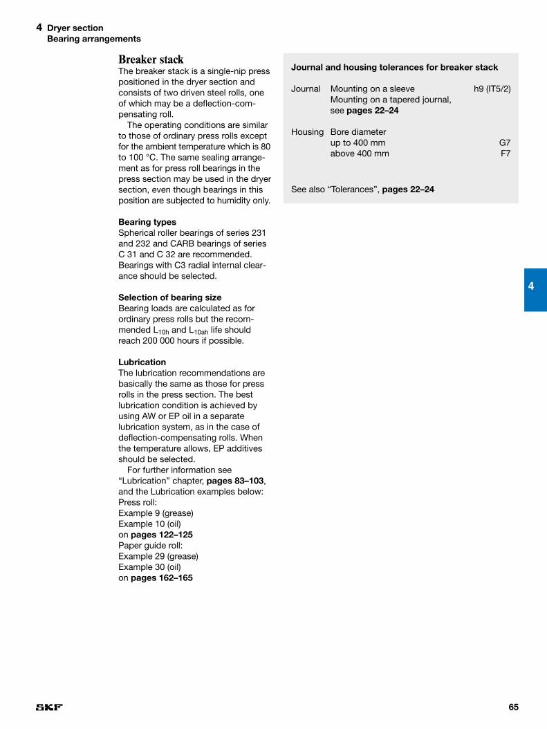
65
4
4 Dryer sectionBearing arrangements
Breaker stackThe breaker stack is a single-nip presspositioned in the dryer section andconsists of two driven steel rolls, oneof which may be a deflection-com-pensating roll.
The operating conditions are similarto those of ordinary press rolls exceptfor the ambient temperature which is 80to 100 °C. The same sealing arrange-ment as for press roll bearings in thepress section may be used in the dryersection, even though bearings in thisposition are subjected to humidity only.
Bearing typesSpherical roller bearings of series 231and 232 and CARB bearings of seriesC 31 and C 32 are recommended.Bearings with C3 radial internal clear-ance should be selected.
Selection of bearing sizeBearing loads are calculated as forordinary press rolls but the recom-mended L10h and L10ah life shouldreach 200 000 hours if possible.
LubricationThe lubrication recommendations arebasically the same as those for pressrolls in the press section. The bestlubrication condition is achieved byusing AW or EP oil in a separate lubrication system, as in the case ofdeflection-compensating rolls. Whenthe temperature allows, EP additivesshould be selected.
For further information see“Lubrication” chapter, pages 83–103,and the Lubrication examples below:Press roll:Example 9 (grease)Example 10 (oil)on pages 122–125Paper guide roll:Example 29 (grease)Example 30 (oil)on pages 162–165
Journal and housing tolerances for breaker stack
Journal Mounting on a sleeve h9 (IT5/2)Mounting on a tapered journal,see pages 22–24
Housing Bore diameterup to 400 mm G7above 400 mm F7
See also “Tolerances”, pages 22–24

66
4 Dryer sectionBearing arrangements
DoctorsSpecially designed multi-row ballbearings mounted direct on cylindricaljournals are recommended for axiallyoscillating doctors.
The bearing arrangement dependslargely upon how the machine manu-facturer has designed and selected theassociated components. A typical bear-ing arrangement is shown in fig .
Selection of bearing sizeFor help with the selection of bearingsize please contact SKF.
LubricationGrease lubrication is normally used for the doctor bearings. Relubricationshould be carried out every 48 hours.When used in the dryer section, hightemperature grease should be selected.
Oil bath lubrication can also be employed, using very high viscositysynthetic oil. The sealing arrangementthen has to be modified.
21
Journal and housing tolerances for doctors
Journal h6Housing J7
See also “Tolerances”, pages 22–24
21Fig
Doctor bearingarrangement


5 Calenders
Bearing arrangements . . . . 72

Calenders
69
5
5 Calenders
Coated paper is calendered or glazed to achievea smoother surface and to make the papershiny. Unglazed coated paper is quite dull andhas a fairly uneven surface. Calendering cancompletely change the character of the paper.
A distinction is made between machinecalendering (or machine glazing) whichis performed in the paper machineitself and supercalendering which iscarried out as a separate operation.The machine calender stack consistsof all-steel rolls and imparts a certainsmoothness to the paper. However, formost grades of coated paper this is notsufficient, and a subsequent glazingoperation in the supercalender is necessary.
Machine calenderThe machine calender is positionedafter the dryer section and consists of astack of two to eight steel rolls restingon top each other (➔ fig ). On pass-ing through the nips between the rolls,the paper is compressed and is givena smoother surface. In an eight-rollstack the web is fed from the top down-wards through seven roll nips withsuccessively increasing nip pressureunder the force of gravity. However, thenip pressures can be increased by ap-plying pressure to the top roll. The king(bottom) roll is usually the driven roll. Itis often a deflection-compensating rollwhich makes for a straight roll nip.
The result of the calendering opera-tion is also temperature-dependent asthe paper is more easily formable thehigher the temperature. It is therefore
1
6
4
3
2
1
5
1Fig
customary to heat one or more of the calender rolls using hot water, oil orsteam for this purpose.
Machine calender1. Spreader roll2. Top roll3. Intermediate roll4. Queen roll5. King roll6. Paper web

Soft calendersAnother type of calendering process,called soft-nip calendering is commontoday. In some cases the soft calender(➔ fig ) is being used to replace boththe machine calender and the super-calender. The soft calender consists ofone or two single-nip calenders withthe linear load being roughly the sameas for supercalenders. One roll is a full-steel one while the other one is madeof steel and coated with a layer of “soft”synthetic material. The main advantagewith a “soft” press nip is that the den-
3
Supercalender The supercalender, which is placedafter the paper machine, consists ofup to 14 rolls stacked one on top of the other (➔ fig ).
The other rolls are carried in arrange-ments which allow them to move inthe upright members of the machineframe and the rolls accordingly rest on top of each other. Pressure can beapplied to the top roll, either by meansof levers, in the case of old super-calenders, or hydraulically, with super-calenders of more modern design.
The linear load in the bottom nip isusually 200–350 N/mm. The supercal-ender is usually driven by the bottomroll and the production speed may beabove 2 000 m/min. The top and bot-tom rolls are usually of the deflection-controlling type.
The feature that chiefly differentiatessupercalenders from machine calen-ders is that alternate rolls in the stackare made of chilled cast iron and rollsof softer material. To treat the paperequally on both sides, the glazing pro-cess is changed by placing two fibrerolls against each other in the middleof the stack. The glazing effect is pro-duced by the sliding that occurs in thenip between the soft and hard rolls.The surface running against the hardroll is given the highest gloss.
To increase the glazing actionssome of the cast iron rolls are usuallyheated by hot water, steam or very hot oil.
2
70
5 Calenders
8
7
6
54
3 2
1
2Fig
5
1
2
4
3
3Fig
Two “soft” calen-ders in tandem forequal treatment ofboth sides of thepaper1, 3. Heated plain
roll2, 4. Deflection-
compensatingpress roll,“soft” coated
5. Paper web
Supercalender1. Unwinding jumbo
roll2. Spreader roll3. Top roll4. Spreader roll5. Fibre roll6. Intermediate
steel roll7. Bottom roll8. Winding jumbo
roll

sity of the paper surface will be moreeven than with a “hard” press nip. Thisgives better printing properties.
As a further development of the soft-calendering process, one of the rolls isheated. Hot water, steam or very hot oil(at temperatures as high as 200–350 °C)is then supplied to the plain roll or tothe deflection-compensating roll.
New calendering conceptThere is a trend towards a multi-niponline calendering process for printingand writing paper grades. Voith Paperhas their “Janus” calenders (➔ fig )and Valmet their “Optiload” concept. Inboth cases, every nip can be individu-ally loaded.
4
71
5
5 Calenders
31
4
5
2
4Fig
Voith Paper Januscalender1. Nipco roll2. Heating roll3. Elastic roll4. Reversing roll5. Paper web

72
5 CalendersBearing arrangements
Bearing arrangementsUnheated plain calender rollsThe top, intermediate and queen rollsin a calender stack can be unheated.Fig shows a basic design of thebearing housing and seals. The outerform of the housing and the fittingholes have to be made to suit theactual calender frame.
Traditionally the bearings have beenmounted on withdrawal sleeves but,owing to demands for improved run-ning accuracy, direct mounting ontapered journals is increasingly common.
Bearing typesOn the drive side, for the top, inter-mediate and queen rolls SKF recom-mends spherical roller bearings ofseries 230 and 231, while bearings ofseries 241 and 232 are used for thebottom rolls of plain type. On the frontside, spherical roller bearings can alsobe used but CARB bearings are moresuitable. Bearings from series C 30 andC 31 are recommended for the top,intermediate and queen rolls, whilstbearings of series C 41 and C 32 areused for the bottom rolls of plain type.
Bearings with C3 radial internalclearance should be selected.
4
4Fig
Bearing arrange-ment for unheatedplain calender roll
Journal and housing tolerances for unheated plain calender rolls
Journal Mounting on a sleeve h9 (IT5/2)Mounting on a tapered journal, see “Tolerances”, pages 22–24
Housing Bore diameterup to 400 mm G7above 400 mm F7
See also “Tolerances”, pages 22–24
For this bearing position, as well asall others with a nip, there is an increas-ing use of bearings that have improvedrunning accuracy (C08 or VQ424). Theneed for these bearings increases withfaster paper speeds.
Selection of bearing sizeThe pressure in the roll contact isbrought about by the mass of the rollsand the applied press load from thetop roll. The top and bottom roll bear-ings have to carry the main load, whilethe bearings of the intermediate rollsare only lightly loaded. The recom-mended L10h and L10ah lives are 120 000 hours.
Bearing selection must always bebased on proper calculations.
LubricationThe lubrication recommendations arethe same as those for plain press rollsin the press section (➔ page 46).
See also the Lubrication examples31–32, pages 166–169.

73
5
5 CalendersBearing arrangements
Heated plain calender rollsThe heating medium is normally sup-plied to the intermediate or the queenroll. Fig shows a suitable bearingarrangement with insulation for a heated roll. The outside form of thehousing and the fitting holes have to bemade to suit the actual calender frame.
SKF always recommends insulation ofthe journals of all kinds of heated rolls.
Bearing typesFor the intermediate and queen rollson the drive side in a calender SKFrecommends spherical roller bearingsof series 230 and 231, whilst bearingsof series 241 and 232 are used for thebottom rolls of plain type.
Spherical roller bearings can also be used on the front side, but CARBbearings are more suitable. For theintermediate and queen rolls SKF recommends bearings of series C 30or C 31, whilst bearings of series C 41and C 32 are recommended for bot-tom rolls of plain type.
In modern high-speed two-roll softcalenders, the heated plain roll is in thetop position of the first nip. This maylead to very light loads on the bearing.For such applications SKF recom-mends use of spherical roller bearingsof series 231 as the axially fixed bearingand CARB bearing of series C 31 as thefree bearing. In cases of very light loadsSKF recommends NoWear™ bearingswith coated rollers (L5DA) (➔ page 26).
The bearings are mounted either onwithdrawal sleeves or direct on taperedjournals. For this bearing position, aswell as all others with a nip, there is an increasing use of bearings havingimproved running accuracy (C08 orVQ424). The need for these bearingsincreases with faster paper speeds.
Calender bearings should have casehardened inner rings (HA3) to reducethe risk of inner ring cracking.
The use of bearings with C3 or, whenthe temperature of the medium heat-ing the roll is above 100 °C, C4 radialinternal clearance is recommended.
Selection of bearing sizeThe pressure in the roll contact isbrought about by the mass of the rollsand the applied press load from the toproll. The top and bottom roll bearingshave to carry the main load, whilst the
5
Journal and housing tolerances for heated plain calender rolls
Journal Mounting on a sleeve h9 (IT5/2)Mounting on a tapered journal, see “Tolerances”, pages 22–24
Housing Bore diameterup to 400 mm G7above 400 mm F7
See also “Tolerances”, pages 22–24
5Fig
Bearing arrange-ment for heatedplain calender roll
bearings of the intermediate rolls areonly lightly loaded.
The bearing selection must alwaysbe based on proper calculations. Therecommended L10h and L10ah lives are120 000 hours.
LubricationThe bearings in this particular applica-tion are lubricated by a circulating oilsystem in which the oil is supplied viathe groove and holes in the outer ringof the spherical roller bearings or fromthe side for the CARB bearings.
The lubrication conditions, such asoil viscosity, oil flow rate and bearingtemperature, for heated calender rollsare calculated principally in the sameway as for drying cylinders.

74
5 CalendersBearing arrangements
Journal and housing tolerances for heated deflection-compensating rolls
Shell supporting bearings:Journal f6Shell (housing) N7
Note! In heated rolls where the bearing temperature may be above 140 °C P7 housing tolerance is recom-mended.
See also “Tolerances”, pages 22–24
LubricationThe lubrication recommendations arebasically the same as those for un-heated deflection-compensating rollsin the press section. The temperatureof the heating media decides what oilviscosity should be selected.
The oil flows for the shell supportingbearings should be large enough tokeep the bearing temperature below80 °C. This is because many of the EPadditives on the market today do notperform satisfactorily at higher tem-peratures. With heated rolls the bearingtemperature can be too high for a mineral oil with EP additives. In suchcases it may be necessary to select asynthetic oil for high temperatureseven though additives in these oilshave proven to be not so efficient.
Sometimes upper roll bearings insoft calenders operate with loads lessthan the minimum load recommenda-tions in the General Catalogue. If so,NoWear bearings with coated rollers(L5DA) should be selected. Alternat-ively, approved polyglycol oils couldbe selected.
For further information see basicrecommendations in the Lubricationexamples 33–35, pages 170–175.
These calculations can be carriedout by SKF using programs, speciallydeveloped for heated calender rolls.
Sometimes upper roll bearings in softcalenders operate with loads less thanthe minimum load recommendations inthe General Catalogue. If so, NoWearbearings with coated rollers (L5DA)should be selected. Alternatively, ap-proved polyglycol oils could be selected.
For further information see the“Lubrication” chapter, pages 83–103and the Lubrication examples 33–35,pages 170–175.
Heated deflection-compensating rollsHeating calender rolls has been practised for many years. The heatingis usually applied to plain calenderrolls but sometimes to the deflection-controlling rolls instead. It has beenstated previously that the deflection-controlling rolls in the press sectionare the most demanding bearing appli-cations in the paper machine due to“rotating misalignment”. This is correctbut the demands made on the bearingscan be even greater if the deflection-controlling roll is heated as well.
Bearing typesWhere shell-supporting bearings aresubjected to normal loads and mis-alignment close to 0,3 degrees, cal-culations have proved that bearings ofseries 230 give the best results. Thishas been verified by practical experi-ence, though each case should beconsidered individually, since bearingsof 238, 239 and 248 series have alsobeen used successfully.
Depending on the operating temper-ature, bearings with case-hardened in-ner rings (HA3) may have to be selected.SKF should always be consulted wherenon-standard bearings are required.
Selection of bearing sizeThe selection of the series and size of the shell supporting bearings is dic-tated by the available space in mostcases. The calculated bearing ratinglife is often very long because themajor share of the nip load is sup-ported via the hydraulic roll crowning.The recommended L10h and L10ah livesare 120 000 hours.


6 Reeler
Bearing arrangements . . . . 78

Reeler
77
When the roll of paper on the reelreaches the desired diameter reeling iscontinued on a new spool (➔ fig ).The jumbo roll of paper is transferredto the slitter and rewinder where it iscut and rewound into rolls of the sizerequired by the customer.
Rolls in modern machines can havea weight of up to 100 tonnes.
16
6 Reeler
Most large paper machines produce a con-tinuous paper web which is 8–10 metres wide.Such a wide and long web has to be cut andmade into smaller rolls before distribution tothe customers. The first reeling, or spool, isdone in the reeler at the end of the papermachine.
1
2
4
5
3
1Fig
Reeler1. Reel spool storage2. Web turn-up to
empty spool3. Reeling position4. Jumbo roll5. Reel drum

LubricationSlow running machines can be greaselubricated, but mostly bearings in thisparticular application are lubricated bya circulating oil system. For sphericalroller bearings the oil is supplied via thegroove and holes in the outer ring ofthe bearing. An annular groove turnedin the housing to coincide with theholes improves lubrication. For CARBbearings the oil is supplied from theside.
For further information see the“Lubrication” chapter, pages 83–103and the Lubrication examples 36 and37, pages 176–179.
Bearing arrangementsThe reeler bearings work in a relativelygood environment. The surroundingsare dry and the temperature is around25 °C. However, it is important for thebearings to be protected from paperdust.
Reel drumsReel drums are normally carried byspherical roller bearings and CARBbearings mounted on adapter sleevesor direct on tapered journals.
A bearing arrangement for a reeldrum is shown in fig . If an adaptersleeve (with abutment spacer) hasbeen incorporated in the design, it isrecommended that an annular groovebe machined in the journal outside thesleeve position. This groove can thenbe used to take a backing ring when ahydraulic nut (HMV) is used to dis-mount the bearing.
Bearing typesSKF recommends spherical rollerbearings of series 231 and 240 as wellas CARB bearings of series C 31.Normal radial internal clearance is recommended.
Selection of bearing sizeThe bearing selection must always be based on proper calculations. Therecommended L10h and L10ah lives are120 000 hours.
2
78
6 ReelerBearing arrangements
Journal and housing tolerances for reel drums
Journal Mounting on a sleeve h9 (IT5/2)Mounting on a tapered journal, see “Tolerances”, pages 22–24
Housing G7
See also “Tolerances”, pages 22–24
2Fig
Reel drum bearingarrangement

the reeled paper and d0 the reel spooldiameter.
A constant mean load, acting on the journal bearing arrangement andequivalent to the real load, can be calculated with the aid of
Km = fm m0
whereKm = constant mean load, acting on the
journal bearing arrangement, Nfm = factor for calculating constant
mean journal load, N/kg, (➔ diagram , page 80)
me = mass of reeled paper, kgm0 = mass of reel spool, kgde = maximum external diameter of
reel, md0 = diameter of reel spool, mnm = constant mean rotational speed,
r/minn0 = maximum rotational speed, r/min
2
Reel spoolsReel spools are generally carried bytwo spherical roller bearings per journal– one mounted on a withdrawal sleeve,the other mounted direct on a cylin-drical journal seating.
The bearing housings (➔ fig ) areusually cylindrical and are designed tofit both in the reeler and the winderwhere the slitting takes place. A lub-rication duct should be provided ineach housing in order to facilitate lubrication of the bearings.
Bearing typesSKF recommends spherical rollerbearings of series 230 and 231.Normal radial internal clearance is recommended.
Selection of bearing sizeDuring the reeling of the paper in themachine and the re-reeling from thereel spool the paper speed is constantand the rotational speed of the reelspool varies. In order to calculate thebearing life, the equivalent speed andload have to be determined. The recommended L10h and L10ah lives are120 000 hours.
The constant mean rotational speednm which, when multiplied by the reel-ing time, will give the same number ofrevolutions as occurs in reality, can betaken from diagram , page 80. nmin relation to maximum speed n0 isshown as a function of de/d0, where deis the maximum external diameter of
1
3
79
6
6 ReelerBearing arrangements
Journal and housing tolerances for reel spools
Journal Mounting on a sleeve h9 (IT5/2)Mounting on a cylindrical seating(100) to 140 mm n6(140) to 280 mm p6
Housing G7
See also “Tolerances”, pages 22–24
3Fig
Reel spool bearingarrangement

For reeling
1 000 000 (C)10/3L10h1 =
60 nm1 P
For re-reeling
1 000 000 (C)10/3L10h2 =
60 nm2 P
whereL10h = basic rating life, operating hoursnm1 = rotational speed for reeling, r/minnm2 = rotational speed for re-reeling,
r/minC = basic dynamic load rating, NP = equivalent dynamic bearing
load, N
nm1 and nm2 are calculated with thehelp of diagram .
The required value L10h is estimatedin relation to the number of reel spoolsavailable. The bearings are generallyoversized.
1
The diagrams and the equation arevalid for reeling as well as re-reeling.
The reel spool has two bearings perjournal (➔ fig , page 79) and thehousing often rests in different wayswhen reeling and re-reeling. Whenreeling, for example, one bearing maytake the full load, whereas the load isshared equally between the two bear-ings during re-reeling.
The re-reeling speed is normallymuch higher, but of course the totalnumber of revolutions is the same forthe two operations. If the bearing loadis different, two values, Fm1 and Fm2,are calculated and then a total con-stant mean bearing load can be calcu-lated using
3 Fm13 + Fm2
3Fm = √ 2
With P = Fm the total life in number ofrevolutions L10 can be calculated withthe aid of the life equation. Since halfof these revolutions are for reeling andhalf for re-reeling, the L10h life in hoursshould be calculated for each opera-tion; the total L10h life will then be
L10h =(L10h1 + L10h2)
2
3
80
6 ReelerBearing arrangements
18
17
16
15
14
13
12
11
10
3 4 5 6
fm
m
m0
de
d0
m0
ded0
= 3 4 5 6
me
e
2Diagram
Diagram for determining factorfor calculation ofconstant meanjournal load
0,6
0,5
0,4
2 3 4 5 6 7
nmn0
de
d0
1Diagram
Diagram for determining theconstant meanrotational speed

81
6
6 ReelerBearing arrangements
Example
A reel spool with a bearing arrange-ment according to fig , page 79, hasd0 = 0,65 m and a mass of 4 200 kg.Maximum paper mass 16 800 kg andthen de = 2,7 m. Paper speed in themachine is 600 m/min, which means294 r/min maximum and 71 r/min min-imum rotational speed. The support inthe machine is such that one bearingat each side takes up the entire loadwhen reeling. During re-reeling thepaper speed is 2 000 m/min with maximum 980 r/min and minimum 236 r/min rotational speed and then allfour bearings share the load equally.What bearing life can be expected for the most heavily loaded bearing?Explorer spherical roller bearings23030 CC(K)/W33, with a basicdynamic load rating C = 510 000 N, are selected.
me 16 800= = 4
m0 4 200
de 2,7= = 4,2
d0 0,65
According to diagram fm = 13,5.
a. When reeling, the maximum bear-ing load is the same as the journalload
Fm1 = Km = fm m0 = 13,5 × 4 200
= 56 700 N
b. When re-reeling, the journal load isshared equally by the two bearings
Km 56 700Fm2 = = = 28 350 N
2 2
The constant mean load is
3 56 7003 + 28 3503Fm = √ = 46 800 N
2
2
3
Since P = Fm
(510 000)10/3L10 =
46 800
= 2 868 million revolutions
c. When reeling n0 = 294 r/min andwith diagram
nm1 = 0,52 × 294 = 153 r/min
1 000 000L10h1 = × 2 868 = 312 400 h
60 × 153
d. When re-reeling n0 = 980 r/min
nm2 = 0,52 × 980 = 510 r/min
1 000 000L10h2 = × 2 868 = 93 700 h
60 × 510
The total basic rating life L10h is thus1/2 (312 400 + 93 700) = 203 050 h fora complete operating cycle, which ismore than enough. The total operatingtime for one roll of paper is in this casetimed as 83,33 + 25,55 = 108,88 min.This corresponds during the basic rating life period to
203 050 × 60 = 111 770 reels of paper
109
LubricationThe bearing arrangements for reelspools are usually lubricated with thesame grease as that used for the form-ing and press section. Relubricationshould be carried out about once amonth. For further information see the“Lubrication” chapter, pages 83–103.
1

7 Lubrication
Why lubricate? . . . . . . . . . . . 83
General notes on lubrication . . . . . . . . . . . . . . 86
Grease lubrication . . . . . . . . 91
Oil lubrication . . . . . . . . . . . . 95
Cleanliness control . . . . . . . 98

Lubrication
83
Why lubricate?Lubrication in earlier timesLubricants are products that pre-datethe industrial age. They have beenused in one form or another for severalthousand years, to fight friction or foras long as man has needed to movebulky objects.
The first great civilisation evolved in the Middle East some six thousandyears ago. Trade, construction and warnecessitated the transport of heavygoods, but it was not always an easymatter.
An Egyptian illustration from somefour thousand years ago demonstratesthe point.
7 LubricationWhy lubricate?
This part of the handbook provides lubricationguidelines for almost all the bearing positions inthe paper machine. By following these guide-lines the user should be able to reduce manycommon bearing failures related to lubrication.
7

1
Oil filmsLubrication plays a major role in rollingbearing performance. The main task of the lubricant is to build up an oil filmbetween the rolling elements and theraceways. The oil film should be thickenough to separate these mating sur-faces completely.
Sometimes the question is askedwhether the radial internal clearance inthe bearing can be too small to allowan oil film to form. This is not the case,even bearings with zero clearance canbuild up an oil film. For example anaverage oil film has a thickness of only0,3 µm. By way of comparison, a sheetof printing paper has a thickness equalto about 200 oil films.
The film thickness in a rolling bear-ing is dictated by the bearing size, theoperating speed and the viscosity atoperating temperature of the oil used.The higher the speed, the thicker isthe oil film. Three different terms areused to describe the lubrication conditions: full, mixed or boundarylubrication (➔ fig ).2
84
7 LubricationWhy lubricate?
What was in the jar, shown in fig ?It could have been water that lubricatedthe runners of the stone sledge as itwas pulled along a roadway of clay orNile mud.
It was also in Egypt, where an ingeni-ous man is said to have discoveredthat, when he stuffed animal fat be-tween the axle and the wheel hub, thecart moved much more easily andwear was also reduced.
Olive oil was the general-purpose fat of the Mediterranean peoples. Theyalso used it when they needed a lubric-ant. Analyses of remains show that the lubricating “grease” used by theancient Egyptians consisted of olive oil mixed with lime.
Mineral oil was also known in veryearly times but it was not used forlubrication. The Indians employed oilin medicines and to make their canoeswatertight.
The story of lubrication began withthese modest experiments using na-ture’s various products, but it was notuntil the 19th century that the fightagainst friction really got into its stride.
1859 is the year usually stated forthe birth of the oil industry. It was thenthat the first oil well was drilled inPennsylvania, USA.
1
Early use of lubricants
Fig

85
The bearings for high-speed suctionrolls are an example of paper machinebearings with full lubrication. Unfortu-nately, there are also some disadvant-ages with increased speed. One is therisk of sliding between the rolling ele-ments and the raceways. If the slidingspeed of rolling elements is too high inrelation to the rolling speed, the oil filmcan be broken. This normally leads toserious damage to the bearing. Insuch cases NoWear™ bearings cansolve the problem (➔ page 26)
Felt roll bearings in the dryer sectionare examples of bearings with mixedlubrication. These bearings do not suf-fer much lubrication-related damagebecause the lubrication conditions arestill relatively good and the speed ismoderate.
The bearings for drying cylinderswithout insulation are examples ofbearings with boundary lubrication.Whether insufficient lubrication in thiscase leads to serious damage or tojust mild wear and running-in of thesurfaces depends on the actual operating conditions.
7
7 LubricationWhy lubricate?
2FigLubrication conditions
full lubrication
mixed lubrication
boundary lubrication

at 40 °C. Tests at SKF show that theoil film thickness at 100 °C, i.e. at the“normal” bearing temperature in thedryer section, is the same for bothmineral and synthetic oils if both have the same viscosity at 40 °C.Therefore, the diagram can be usedfor both mineral and synthetic oils. It is based on the viscosity index VI = 85. However, at temperaturesabove approximately 130 °C theadvantage of the high viscosity index of synthetic oils is significantand should therefore be taken intoconsideration.
Bearing life factors a23 and aSKFWhen the κ value is known diagramcan be used to find out the value of the
3
86
7 LubricationGeneral notes on lubrication
100000
50000
1000020000
n=
500
5000
2000
1000
100200
50
20
5
10
2
50020103
5
10
20
50
100
10050 200
200
500
1000
20001000
dm mm
mm2/sν1
1Diagram
ν1 diagram with anexample
Viscosity classes Kinematic viscosity according mm2/s at 40 °C (104 °F)to ISO min mean max
ISO VG 68 61,2 68 74,8ISO VG 100 90,0 100 110
ISO VG 150 135 150 165ISO VG 220 198 220 242ISO VG 320 288 320 352ISO VG 460 414 460 506
ISO VG 680 612 680 748ISO VG 1 000 900 1 000 1 100ISO VG 1 500 1 350 1 500 1 650
1Table
Viscosity classaccording to ISOstandards
General notes on lubricationBasic termsWhen selecting suitable lubrication forrolling bearings there are some basicterms that need to be known.
Kinematic viscosity νThe kinematic viscosity ν describesthe resistance to flow of the oil at acertain temperature. Low values meanthat the oil flows easily, high valuesthat the oil flows sluggishly. The unitfor viscosity is mm2/s (previouslyknown as Centistoke).
Table lists the ISO classificationof oils used in paper machines. Thefour classes in bold text are commonlyused for circulating oil systems.
κ valueκ is a viscosity ratio which shows therelation between the operating viscosityof the oil ν and the required viscosityν1 both at operating temperature, i.e.
νκ = ν1
Diagram is used to determine ν1.When ν1 is known diagram is used to select an oil that gives therequired viscosity at the operatingtemperature. κ = 1 is intended for gen-eral applications and there are specialrecommendations for paper machinebearings (➔ pages 207–208).Example: A bearing 23130 CCK/C4W33(d = 150 mm, dm = 200 mm) running at 700 r/min needs a viscosity of 13 mm2/s at working temperature (➔ diagram ). If the bearing runs at90 °C and selecting an oil with a vis-cosity of 220 mm2/s at 40 °C, theobtained κ value is 2 (➔ diagram ).
Viscosity index (VI)The viscosity of an oil changes withthe temperature. The viscosity index isa way to describe the magnitude of thechange for a specific oil. Synthetic oilsnormally have a much higher viscosityindex than mineral oils, i.e. their tem-perature dependence is less.
Diagram is used when the vis-cosity at the operating temperature isconverted into the reference viscosity
2
2
1
21
1

212100
1046820
5
10
20
30
14040 60
17680
500
200
100
60
40
ν, ν1 mm2/s
1000
2000
320284140
248120 160 t °C
t °F356180
87
7
7 LubricationGeneral notes on lubrication
a23 factor. Bearing life adjustment fac-tor a23 will either increase or decreasethe calculated bearing life (exceptwhen κ = 1).
This diagram can be used for allcommon paper machine lubricantswith EP or AW additives provided theadditives are not aggressive to steel,see remarks in section “Different types
2Diagram
0,5
0,1
0,050,05
0,2
0,20,1
2
0,5
1
5
1 2 105
a23
κ
3Diagram of additives”, pages 88–89. Highervalues may be obtained (shaded area)if lubricants containing additives of theEP or AW type are used, the watercontent is below 200 ppm and thecontamination level low.
In the SKF Life Method the life factora23 is replaced by a life adjustmentfactor, called aSKF. The advantage withthis factor is that it takes both the vis-cosity ratio κ and the lubricant cleanli-ness into account. The cleanliness inthis case means the representativeparticle concentration in the lubricat-ing oil during continuous operation (➔ page 12).
The number of “clean” lubricationsystems is increasing every year asmore efficient filters are introduced.However, continuous monitoring of thecleanliness is still uncommon.
When dimensioning the bearingarrangements for paper machines SKFrecommends the use of the SKF LifeMethod (aSKF).
For further information see “Selectionof bearing size”, pages 10–12.Viscosity/tempera-
ture diagram withan example of κcalculation
Diagram for bear-ing life adjustmentfactor a23
3. The actual ISO VG 220 oil has a viscosity of 220 mm2/s at the reference temperature 40 °C
2. Required oil viscosity at the reference temperature 40 °C is 77 mm2/s
4. Actual oil viscosity at operating temperature 90 °C, ν = 26 mm2/s
1. Required oil viscosity at operating temperature 90 °C, ν1 = 13 mm2/s
5. κ = ν/ν1 = 26/13 = 2,0 for this example

88
7 LubricationGeneral notes on lubrication
Anti-foamThe foam-damping action can beobtained, for example, by adding smallquantities of silicone fluid. Such addit-ives cause the bubbles to burst whenthey come in contact with the surfaceof the oil in the reservoir. Air in the oilgives shorter oil and bearing life.
Anti-oxidantOil exposed to high temperatures andcontact with air oxidises, i.e. chemicalcompounds are formed. These com-pounds can increase the viscosity of the oil and also cause corrosion.Viscosity increase is normally used asone criterion for oil change, becausethese oxidation compounds have anegative influence on the lubricationeffect. Anti-oxidants improve the ox-idation stability of the oil by 10 to 150times. The performance of the oil ismaintained longer, which also meansthat the cost of the oil will decreasebecause it will last longer. Furthermore,these additives have an anti-corrosiveeffect but it is relatively limited.
Lubricant test
Different types of additivesProduction of all different lubricatingoils begins with a straight base oil, i.e.an oil without any additives. The differ-ence between hydraulic, gear, engineand paper machine oils is the additivepackage, i.e. the combination of dif-ferent additives. Gear oils, for example,may very well be used in paper ma-chines if the additive package is suitable.
The function of additives is an areaof very intensive development. Newproducts are presented as replace-ments for products found to be toxic.For example, the use of products con-taining lead and also chlorine is prohib-ited in most countries. Explanationsare given below of the functions ofsome common additives in papermachine oils.
Anti-corrosionThere are in principle two types ofadditives which offer protection. Theyare either water-soluble or oil-solublechemicals, e.g. sodium nitrite. Suchadditives normally give sufficient pro-tection in damp operating conditions.However, they cannot give completerust protection if the water content inthe lubricant is too high. This is perhapsthe biggest problem for the bearings in the forming and press section.

89
7
7 LubricationGeneral notes on lubrication
EP (extreme pressure)If the oil film in the rolling contact isnot thick enough to fully separate thesurfaces, there will be an interactionbetween the mating surfaces causingvery high local temperatures. The tem-perature can be so high in these hotspots that asperities are weldedtogether. This creates high friction andheavy adhesive wear like smeared surfaces in the bearing (➔ pages 204–205).
EP additives cause a chemical reaction in any hot spots so that theasperities shear off instead of beingwelded together. The result is asmoothing effect which reduces thesize of surface irregularities. As thecalculated κ value is based on the surface finish of the raceways beforethe bearing has been in operation, thissmoothing effect will lead to an in-crease in κ value in operation whenlubricants with good EP additives areused. After some time the surfacesshould be fully separated by the oilfilm.
Many common modern EP additivesare of the sulphur/phosphorus type.These additives, tend to be aggressiveto bearing steel at elevated temperat-ures and therefore reduce bearing life.As such, SKF generally recommendsthat lubricants with EP additivesshould not be used for bearings withoperating temperatures above 80 °C.Of course, this can be discussed withyour oil supplier.
In lightly loaded bearings where therollers have a risk of extensive slidingduring operation, EP additives normal-ly do not work. For these applicationswe recommend NoWear™ bearingswith coated rollers (L5DA) (➔ page 26).
AW (anti-wear)At temperatures above 80 °C whereEP additives should not be used, werecommend AW additives to reducethe risk of wear and smearing in thebearing. Additives of the AW type forma surface layer with certain beneficialproperties such as a stronger adhesionto the surfaces. This surface layercauses the asperities of the matingsurfaces to slide over each otherinstead of shearing off.
Also EP additives are sometimescalled wear-prevention additives,because they prevent adhesive wear.This is perhaps why some markets donot distinguish between AW and EPadditives. Both of them are called EP.
DetergentThese additives may be described as “cleaning” additives. They work insuch a way that reaction products fromhigh-temperature zones are kept float-ing in the oil. Without these additivessuch reaction products may adhere toand discolour the surfaces in contactwith the oil. These additives are norm-ally used in engine oils for cars butsometimes feature in paper machineoils as well.
DispersantOne way to avoid sedimentation ofcontaminant particles inside the longpipes and large reservoirs of paper-machine lubrication systems is to usean oil with dispersant additives. Theseadditives can keep the particles float-ing in the oil until they enter the oil fil-ter. One drawback of these additives isthat they can keep small drops ofwater floating as well. This may causecorrosion in the bearings and cloggingof the oil filters. Another drawback isthat these additives can neutralise theeffect of anti-wear additives.
VI-improvementThese viscosity index (and sometimesviscosity) increasing additives are oftenmade up of large-molecule polymers.Experience with high-viscosity oilsshows that these additives can besheared to smaller molecules, i.e. theviscosity of the oil will decrease. If that happens the thickness of the oilfilm in the bearings will also decrease.Therefore additives of this type are not recommended for paper machineoils. These additives are very commonin engine oils for cars, but papermachine oils must have a much longerservice life without any change ofbasic properties like viscosity.
These additives may influence thefilterability of the oil.

90
7 LubricationGeneral notes on lubrication
Grease or oil lubricationWhether a rolling bearing is to be lub-ricated with grease or oil depends ona number of factors.
Grease has the advantage over oilof being easier to retain inside thebearing housing. It can also be retainedin the sealing labyrinths where it pro-tects the bearing against damp andimpurities. A disadvantage when relub-ricating with large amounts of greaseis that the used grease must come outthrough the labyrinths. This may causecontamination of the wire and thepaper web.
Oil lubrication is used when theoperating temperature with greaselubrication (due to high speed and/orheating) would be too high. A commonmaximum operating temperature formedium temperature greases in theforming and press section is 75 °Cand for high-temperature greases inthe dryer section 120 °C.
However, SKF recommends circu-lating oil for all bearings in the dryersection, to enable cooling and clean-ing of the oil. Unfortunately circulatingoil lubrication is not possible for all the
bearing positions, e.g. rope pulleys,spreader rolls, doctors and steamjoints. Grease is used for all thesepositions. In old machines the felt rollsare grease lubricated too.
To select an appropriate lubricant itis necessary to know the operatingtemperature of the bearing. The tem-perature can either be calculated bySKF with the help of computer pro-grams or by measuring in the machine.

91
7
The aim with both automatic andmanual lubrication is to supply theright amount of fresh grease to thebearing arrangement.
Examples of disadvantages withgrease lubrication are the difficulties inselecting grease quality, initial charge,relubrication quantity and method ofgrease supply into the bearing.
Grease lubricationGrease lubrication systemTraditionally, most of the forming andpress section bearings, as well as ropepulley and doctor bearings in the dryersection have been grease lubricated.There are a number of reasons for thisbut, today the main consideration iscost. SKF does not recommend greaselubrication in the dryer section. For therope pulley, doctor and spreader rollbearings where it is very difficult toapply oil lubrication, grease lubricationis used as a compromise.
Previously, when production speedswere low, relubrication was carried outmanually during maintenance stops i.e.once or twice per month. More frequentrelubrication is necessary today due to increasing speeds, high-pressurecleaning of the machine and increaseddemand for machine reliability.
Therefore, the use of automaticlubrication is becoming increasinglypopular. Automatic lubrication sys-tems consist of a number of compon-ents (➔ fig ).3 Automatic grease
lubrication
3Fig
7 LubricationGrease lubrication

92
7 LubricationGrease lubrication
Selection of grease typeLubricating grease is made up of a so-called base fluid which is mixed witha thickener. The base fluid is normallyeither a mineral or a synthetic oil, oftenreferred to as the base oil.
The thickener in the majority of casesis a metal soap, e.g. calcium, lithium,sodium, or non-soap, e.g. clay (ben-tonite), silica gel, polyurea. The consis-tency of the grease depends on thetype and quantity of the thickener used.The consistency is measured as thepenetration depth of a standardisedcone into the grease during a certaintime. Table shows three consistencyclasses according to NLGI (NationalLubricating Grease Institute), whichare used for bearing applications.
When selecting greases for papermachines it is necessary to take all op-erating conditions into consideration.Unfortunately, there has been a trend,mainly in response to end-user require-ments, to minimize the number of dif-ferent greases. That may lead to anunsatisfactory compromise. For ex-ample, it may be hard to find a greasethat has all the properties required forboth the forming and press section aswell as the dryer section.
SKF lubricating grease rangeWith the improvements in bearinglubrication technology, higher operat-ing speed and temperatures the de-mands made on lubricating greaseshave become more severe. SKF, in conjunction with major grease manu-facturers, has developed a range oflubricating greases to satisfy thesedemands.
The most common greases used inpaper machines are the medium tem-perature grease LGEP 2 and the hightemperature grease LGHB 2.
Detailed information concerningthese greases and all other productscan be obtained from your local SKFcompany.
Greases for the forming and presssectionThe SKF experience is that a greasesuitable for lubricating the rolling bear-ings in the forming and press sectionshould have the following basic properties:
2
Consistency classes
NLGI Penetrationindex mm/10
1 310–340 (very soft)
2 265–295 (soft)
3 222–250 (medium hard)
2Table
• Good lubrication function up to 75 °C• Consistency, NLGI 2• Base oil viscosity, min. 175 mm2/s
at 40 °C• Excellent corrosion protection• Good water washout resistance
Recommendation: SKF LGEP 2.
Greases for the dryer sectionSKF experience is that some of theso-called high-temperature greaseswith a minimum base oil viscosity of400 mm2/s have shown adequatelubrication performance in the dryersection.
A grease suitable for lubricating roll-ing bearings in the dryer section shouldhave the following basic properties:
• Good lubrication function up to 120 °C• Consistency, NLGI 2• Base oil viscosity, min. 400 mm2/s
at 40 °C• Good oil bleeding• Long service life
Recommendation: SKF LGHB 2.
Grease quantity at installationIn general, during the initial mounting,the bearing should be completely filledwith fresh clean grease. Furthermore,30 to 50 % of the free space in thehousing should be filled with grease.
In addition, to ensure sealing effici-ency, the labyrinth seals should becompletely filled with grease from thebeginning.

93
7 LubricationGrease lubrication
RelubricationThere are some important issues toconsider when relubricating. One basicrule is to use the same grease qualityfor relubrication as was previouslyused when the bearing was mounted.
Another important point to consideris the method of relubrication. In mostcases, there is a need of regular relub-rication. Therefore the housing must be supplied with a lubricant duct and grease nipple. For the fresh grease topenetrate effectively into the interior ofthe bearing, and for the old grease tobe pushed away, the duct should openso that the grease is supplied immedi-ately adjacent to the outer ring face ordirect into the lubrication groove (W33feature).
The bearing housings in most papermachine applications with grease lub-rication, are provided only withlabyrinth seals. These labyrinths haveto be filled with grease to obtain an
7
efficient sealing function. Therefore,the recommended relubrication inter-vals and quantities are selected tosecure both good lubrication and effi-cient sealing function.
The grease in the labyrinths caneasily be washed out, if the housingsare hosed down under high pressure.Therefore, never direct the high-pres-sure spray nozzle towards the sealinggap. The housing sealing should beprotected e.g. with splash covers (➔ fig , page 33).
Sometimes extra relubrication is car-ried out during a standstill in order topush the water-contaminated greaseout from the labyrinth. This extra relub-rication should instead be carried outunder operating conditions just beforestandstill. More details are given underthe heading “Standstill precautions”(➔ page 196).
8

Relubrication intervals and quantitiesAs the bearing arrangements in theforming and press section of the papermachines have a “wet” environment,there is a need for shorter relubricationintervals than those indicated in theSKF General Catalogue.
There are basically three factors toconsider when selecting relubricationintervals and quantities. These are thelubrication and sealing functions andthe grease leakage from the housing.
From a lubrication point of view, theamount of grease in the bearing shouldbe just sufficient to supply an adequatequantity of base oil to the raceways,rollers and cages.
From a sealing point of view, it isimportant that the labyrinth seals arealways completely filled with grease.
From a leakage point of view, thegrease quantity should not be too large.Large quantities of grease generateheat in the bearing, especially at highspeeds, when the bearing attempts topump out most of the grease. Whenrelubrication has been carried out anumber of times all the free space in-side the housing can be filled with grease. From then on, the grease leak-age will be equal to the relubricationquantity. Therefore, with large regreas-ing quantities, there is a risk that theleakage is so great that some greasemay come out on the wire.
As the environment and the bearinghousing design vary widely frommachine to machine, the relubricationquantities should always be adjustedaccording to practical experience.Thus, the recommended values forrelubrication intervals and quantitieslisted in tables and should beused as guidelines only.
43
94
7 LubricationGrease lubrication
Manual lubrication
Automatic lubrication
Forming and press sectionOnce a week is recommended for bearings in wet positions, as in the wire and press parts.
Once a month is recommended forbearings in damp positions, e.g. calenders, reelers, winders.
Quantities according to
G = k D B
whereG = quantity of grease, gD = bearing outside diameter, mmB = bearing width, mmk = 0,002 (weekly relubrication)
0,003 (monthly relubrication)
Dryer sectionManual grease lubrication is not to berecommended in the dryer sectionbecause of the difficulty in reaching allthe positions during operation.
3Table
Forming and press sectionAutomatic grease lubrication systems are becoming increasingly common, The advantage with these systems isbetter protection of the bearing be-cause of shorter relubrication intervals.
Quantities according to the equationbelow are valid for bearings in the wireand press sections.
G = 0,00001 H D B
whereG = grease quantity after H hours, gD = bearing outside diameter, mmB = bearing width, mmH = relubrication interval, hours
Dryer sectionSKF normally recommends oil lubrica-tion for the bearings in the dryer sec-tion. However, there are some positionswhere circulating oil is difficult to apply.For these positions SKF recommends ahigh-temperature grease with the samequantities as above.
4Table

95
7
7 LubricationOil lubrication
Oil lubricationOil lubrication systemsMost of the bearings in old machineswere grease lubricated. Originally, onlythe bearings for drying cylinders had oillubrication. These first oil lubricationsystems were of the oil bath type.
Increased operating speeds andsteam temperatures soon made im-proved lubrication necessary. The higher the operating temperature of thebearing, the more rapidly the lubricat-ing oil will degrade.
The next step in improved lubricationwas the introduction of oil drip lubrica-tion. With this method it was possible toextend the life of the oil. However, thecontinuous increase in paper speedsand steam temperatures and the intro-duction of hooded dryer sections verysoon resulted in bearing operating conditions that required even betterlubrication. This was obtained by intro-ducing circulating oil lubrication.
Modern circulation systems make it possible to cool and clean the oil (➔ fig ). These are the main reasonswhy circulating oil lubrication is usedfor most bearings in new machines.
Over the years, the speed increasehas been so great that other parts ofthe machine also have to be lubricatedwith circulating oil. Note that the speed
4
rating in the SKF General Catalogue isnot the maximum permissible speedfor the bearing. With oil circulation it ispossible to operate at higher speeds.Some bearings in modern high-speedmachines operate at double the speedrating.
Modern paper machines are oftenvery large and the bearing operatingconditions differ in the various parts of the machine. Therefore the bearinglubrication system is split up into sev-eral smaller systems. For example, theforming and dryer sections usuallyhave their own lubrication systems, as do the Yankee cylinders and deflection-compensating rolls (➔ fig , page 96).5
21
3
4
5
6
M
16 17
15
14
13
7
8 9 10
12
11
4Fig
Basic layout of a circulating oillubrication systemfor a papermachine1. Suction tube filter2. Heater3. Pump (with motor)4. Duplex filter5. Cooler (with
thermostat)6. Pressure control
valve7. Thermometer8. Oil sampler9. Flow control10. Flow indicator11. Rolling bearings12. Speed reducers13. Return tube14. Intermediate wall15. Reservoir16. Drain17. Water extractor

96
7 LubricationOil lubrication
Synthetic oilsThere are a number of different typesof synthetic base oils such as syn-thetic hydrocarbons, esters and poly-glycols. These products have differentproperties regarding their influence onrubber seals, evaporation and miscibil-ity with polar and non-polar additivesetc. Another difference is that the den-sity of polyglycols is very close to thatof water at 50 °C. This is a disadvant-age e.g. the water will not separate inthe reservoirs which normally have atemperature of about 50 °C.
Poly-alpha-olefin (PAO) oils (oftenmixed with small amounts of other syn-thetic base oils) have been the mostpopular synthetic oil type in papermachines. This is perhaps due to thefact that these oils do not have theabove-mentioned drawbacks.
Synthetic oils have a number ofadvantages compared with mineraloils. The most appreciated property of synthetic oils is perhaps their betterperformance at high operating tem-peratures. Therefore, these oils areoften used at operating temperaturesabove 100 °C, but they can of coursebe used at lower temperatures as well.
Oils for the forming sectionThe selection of oil for the formingsection should be based on operatingconditions for press and suction rollbearings because these are the mostdemanding positions.
Selection of oil qualityWhen selecting oils for paper machinesit is necessary to take into considera-tion a great number of factors including:
• Lubrication method (oil bath/circula-tion)
• Operating conditions for all the bearings connected to the samelubrication system
• Design and performance of the seals• Pipe dimensions
The most common operating condi-tions usually result in two or three dif-ferent oils in one machine. This repres-ents a good compromise between thedifferent lubrication requirements andwhat is practical.
Unfortunately, there has been atrend, mainly in response to end-userrequirements, to minimise the numberof different oils. That may lead to anunsatisfactory compromise. For ex-ample, it may be hard to find an oilthat has all the properties required forboth the forming and dryer sections.
Mineral oilsIn most cases good-quality mineraloils are suitable as lubricants for papermachine bearings at operating tem-peratures up to 100 °C. However,some mineral oils (developed for papermachines) perform well up to 120 °C.
12
31
4
5 67
8
7 9 10
11
613
12
16
14 15
5Fig
Basic layout of a paper machineincluding a commondivision in differentoil lubrication systems. 1. Wire roll2. Forward drive roll3. Forming roll
(suction roll)4. Suction couch roll5. Pick-up roll6. Spreader roll7. Felt roll8. Shoe press9. Drying cylinder10. Vacuum roll11. Guide roll
(wire roll)12 Deflection com-
pensating pressroll (soft calender)
13. Thermo roll (soft calender)
14. Reel drum15. Reel spool16. Paper web
Forming section system Dryer section system Calender system

97
7
7 LubricationOil lubrication
Good thermal and chemical stabilityare the most important properties ofoils for the dryer section and machinecalenders. Effective rust inhibition isdesirable here as well.
An oil suitable for the dryer sectionshould have the following basic prop-erties:
• Viscosity classes:ISO VG 220 to 320 for drying cylinders etc.ISO VG 320 to 460 for Yankee cylinders ISO VG 460 to 1500 for oil baths
• EP additives up to 80 °C• AW additives above 80 °C• Rust inhibiting additives
The operational limits for the oil arespecified in the section “Cleanlinesscontrol” (➔ pages 98–102).
Oils for off-line calendersOff-line calenders are often made upof ordinary press rolls. Therefore, therequirements for calender oils are thesame as for forming section oils if thebearing operating temperature isbelow 80 °C. However, in some off-line calenders, bearings are operating atthe same temperatures as dryer sec-tion bearings. In these cases the oilsshould fulfil the requirements for dryersection oils.
Calender development is very rapid.Heating oil in so-called hot calendersmay have temperatures up to 350 °C.Special oils and lubrication systemsare required if the temperatures of thepress roll bearings in these hot calen-ders is much higher than those of thebearings in the dryer section.
The operational limits for the oil arespecified in the section “Cleanlinesscontrol” (➔ pages 98–102).
When large bearings with heavy rollers rotate at high speeds the rollersmay slide as they enter the loadedzone. The interior surfaces of suchbearings may be damaged severely bysmearing. That is why these bearingsneed a thick oil film containing EPadditives. If these additives are of thesulphur-phosphorus type, the bearingoperating temperature should notexceed 80 °C as such additives actaggressively at higher temperatures.Therefore, the oil flows should be largeenough to keep the bearing temperat-ure below 80 °C. Oils with EP additivesthat are stable at higher temperaturesor with AW additives should be used atoperating temperatures above 80 °C.
Effective rust-inhibition and rapidwater separation are the most import-ant properties of oils for the formingsection, but EP additives are also oftop priority for high-speed press and suction rolls.
An oil suitable for the forming sec-tion should have the following basicproperties:
• Viscosity class ISO VG 220 or 320• EP additives up to 80 °C• Anti-wear additives above 80 °C• Rust inhibiting additives
The operational limits for the oil arespecified in the section “Cleanlinesscontrol” (➔ pages 98–102).
Oils for the dryer section andmachine calendersThe selection of oil for the dryer sec-tion should be based on operatingconditions for drying and Yankeecylinder bearings because these arethe most demanding positions.
EP or AW additives are also recom-mended for oils in the dryer sectionbecause the high bearing operatingtemperatures in combination with theviscosity of commonly used oils leadsto metal-to-metal contact betweenrollers and raceways. If the EP addit-ives are of the sulphur-phosphorustype the bearing operating temperat-ure should not exceed 80 °C as theseadditives act aggressively at highertemperatures. Oils with EP additivesthat are stable at higher temperaturesor with AW additives should be usedat operating temperatures above 80 °C.

98
7 LubricationCleanliness control
Cleanliness controlLubricating oil should be continuouslycleaned of impurities. It is important toremove both water and solid particlesfrom the oil.
Cleanliness recommendationWhen selecting suitable water extrac-tors and filters the following cleanlinessguidelines should be aimed for:
a) Water content should be below 200 ppm.
b) Particle content should be accord-ing to ISO 4406 cleanliness class –/15/12 (using a microscope) or18/15/12 (using automatic particlecounter) or SAE class 6B/6C, orbetter.
Water extractorsAs mentioned earlier, SKF has foundwater to be one of the major reasonsfor short service live of bearings. Therecommendation for water content tobe below 200 ppm gives a good bal-ance between the cost of water removaland increased bearing service life.
The recommended water contentlevel can easily be obtained by usingordinary extractors available on themarket. The most common extractorswork according to two basic prin-ciples, using vacuum or centrifugalforces. The advantage of the centrifugalextractors is that they normally removemore water per minute than the vacuumextractors. On the other hand, vacuumextractors have the advantage thatthey take air out as well.
The final result of water removaldepends very much on the amount ofwater entering the system. Therefore,the main question when selectingequipment is the estimation of the riskof water entering into the lubricationsystem. The most common reasons forthe entry of water are inefficient housingsealings and high-pressure cleaning,but accidental leakage from oil coolersetc. has to be considered as well.
The bearings should never be ex-posed to oil that has higher water con-tent than that recommended. This isespecially important during standstill.If this does happen there is a great riskthat the free water in the oil can startthe corrosion process. Therefore, it is
very important to keep water contentlow just before machine stoppages and to prevent entry of water duringstandstill.
Other causes of high water contentin modern paper machine oils are so-called dispersant additives. The maintask of these additives is to keep allcontaminant particles floating in the oiluntil they enter the oil filters. Unfortu-nately, these additives sometimes havethe same effect on water molecules.This is one of the reasons for the clog-ging of oil filters. In such cases thecontinuous use of a water extractor is required.
From the bearing point of view, all oillubrication systems should have equip-ment for continuous water removal.Without such equipment many papermachine oils may have water contenthigher than the recommended 200 ppm.
Oil filtersDifferent types of oil filters have beenused for many years in the lubricationsystems of paper machines. The firstreplaceable filters were so-called meshelements made of woven steel wire.These filters were efficient when it cameto very large particles but research atSKF has proved that even particlessmaller than 10 µm should be removedfrom the oil because they may have adetrimental effect on bearing surfaces.
Normally there is a connection be-tween fine filters and clean oil.
However, the most important thing isto have clean lubricating oil. Therefore,SKF’s recommendation is based on oilcleanliness instead of filter ratings, seeunder “Cleanliness recommendation”.This recommendation is based on theoptimised filter cost as well as on thebearing service life obtained.
When selecting filters, the filterabilityof the current oil should also be con-sidered.
Filter ratingsFilters have developed rapidly in recentyears. This means that the “standard”filters of today are many times moreefficient than the filters commonly usedsome years ago.
The filter rating should give an indica-tion of the filter efficiency. Unfortunately,in the case of so-called “nominal” filtersthere is no definition of the efficiency.

99
7
7 LubricationCleanliness control
Efficiency of the filters is defined as a reduction factor β which is relatedto one particle size. The higher the βvalue, the more efficient the filter is forthe specified particle size. Thereforeboth the β value and the specified particle size have to be considered.
The reduction factor β is expressedas the relationship between the num-ber of specified particles before andafter the filter. This can be calculatedas follows:
n1βx = n2
wheren1 = number of particles per volume
unit (100 ml) larger than x µmupstream the filter
n2 = number of particles per volumeunit (100 ml) larger than x µmdownstream the filter
Note! The β value is connected to onlyone particle size in µm, which is shownas the index e.g. β3 , β6, β12, etc. Forexample, a complete rating β6 = 75means that only 1 of 75 particles of 6 µm or larger will pass the filter.
Particle countingParticle counting can be based on various principles.
The simplest is to filter the oil on toa membrane and look at it through anoptical microscope. The size of a par-ticle is established by measuring the
longest dimension. The particle sizedistribution can be estimated by comparing the sample membrane with reference membranes of differentcleanliness levels. A skilled operatorshould do this because it is a subjec-tive method.
Automatic Particle Counting (APCanalysis) is a method more commonlyused. Particles are passed in front of alight source coupled to a sensor. Theamount of light passing through a win-dow depends on the size of the parti-cle passing that window. The particlesize is derived from its cross-sectionalarea. Calibration of the equipment ismost important. A drawback of usinga sensor is the necessity of removingair bubbles, which would otherwise becounted as particles.
Yet another method for particle ana-lysis is Spectro-metric Oil AnalysisProgram, also called SOAP. Thismethod is very good for the analysis of small particles e.g. from abrasivewear. Wear particles are in most casessmaller than 5 to 10 µm.
There are a number of additionalmethods and equipment on the markettoday and new products are launchedall the time in this growing field of con-dition monitoring.
Whatever the method used theresults should be presented as a devel-opment trend. Fig shows how a PCis connected to APC equipment to collect and evaluate the results.
Errors are to be expected if theresults of an analysis show that there
6
6Fig
Equipment for particle counting

ISO classification and example for both microscope (–/15/12) and automatic particle counter (18/15/12)
ISO classification – allocation of scale number
Number of particles per ml oilOver Up to and Scale
including number
2 500 000 >281 300 000 2 500 000 >28640 000 1 300 000 >27320 000 640 000 >26160 000 320 000 >25
80 000 160 000 >2440 000 80 000 >2320 000 40 000 >2210 000 20 000 >215 000 10 000 >20
2 500 5 000 >191 300 2 500 >18640 1 300 >17320 640 >16160 320 >15
80 160 >1440 80 >1320 40 >1210 20 >115 10 >10
2,5 5 >91,3 2,5 >80,64 1,3 >70,32 0,64 >60,16 0,32 >5
0,08 0,16 >40,04 0,08 >30,02 0,04 >20,01 0,02 >10,00 0,01 >0
4Diagram5
100
7 LubricationCleanliness control
are very big differences between thedifferent particle size ranges. If thereare too many large particles the filtermay be damaged or by-passed.Another reason could be that the oilhas not been correctly sampled. Itmay include sediment particles. Thepresence of too many particles resultsin a “step” in the distribution curve.This “step” shows the performancelimit of the filter.
Contamination levelsStandards establish information as toallow comparison and interpretation ofcontamination (cleanliness) levels andhence enabling control of particle con-tamination to ensure system perfor-mance and reliability. Standards havebeen published by ISO, NAS and SAE(both Aerospace Standards).
ISO 4406 method ISO classification
ISO classification methodThe method for coding the contamina-tion level in a lubrication system isaccording to ISO 4406:1999.
In order to simplify the reporting of particle count data, the quantitiescounted are converted in a code usingscale numbers. These are allocatedaccording to the number of particlescounted per millilitre of the fluid sample (➔ table ).
The code for contamination levelsusing automatic particle counters (APC)comprises three scale numbers relatingto the number of particles ≥ 4 µm (c), ≥ 6 µm (c) and ≥ 14 µm (c), where (c)refers to APC. The three numbers arewritten one after the other separatedby oblique strokes (slashes). Example:18/15/12 (➔ diagram ). APC calib-ration is according to ISO 11171.
For comparative results, the code formicroscope counting comprises twoscale numbers relating to the number
4
5
10
10
10
10
10
10
1
10
10
6
5
4
3
2
–1
–2
>28
28
27
26
25
24
23
22
21
20
19
18
17
16
15
14
13
12
11
10
9
8
7
6
5
4
3
2
1
2.5
1.3
6.4
3.2
1.6
8
4
2
5
2.5
1.3
6.4
3.2
1.6
8
4
2
5
2.5
1.3
6.4
3.2
1.6
8
4
2
4–
65
1415
Num
ber
of p
artic
les
per
mill
ilitr
e la
rger
tha
n in
dic
ated
siz
e
Particle size, µm (c)Particle size, µm
Sca
le n
umb
er
Table

101
7
7 LubricationCleanliness control
of particles ≥ 5 µm and ≥ 15 µm.Counting is undertaken in accordancewith ISO 4407. The code is stated inthree part form where the first part isgiven as a “–”. Example: –/15/12 (➔ diagram ).
NAS classification methodThe NAS classification method isaccording to NAS 1638. The principalmeans for its development was tocount particles with a microscope(according to ARP598). The strengthof the method was the ability to pro-vide more details about the particledistribution by considering five sizeranges. NAS 1638 is superseded bySAE AS 4059.
SAE classification methodThe classification method is accordingto SAE AS 4059. The contaminationlevels selected are an extension to theNAS 1638 levels. However, the SAEstandard considers both microscopeand automatic particle count.
For reporting, the quantities countedare converted in class codes. Theseare allocated according to the numberof particles counted per 100 millilitre ofthe fluid sample (➔ table ).
The particle distribution considerssix size ranges (size code by a letterfrom A to F) and 15 classes.
The SAE cleanliness levels can beidentified in different ways, the mostimportant ones:
6
4
• total number of particles larger thana specific size, example: AS 4059class 6B
• designating a class for each sizerange, example: AS 4059 class6B/5C/4D/4E where the figure indi-cates the class and the letter theside code (➔ table ).
Flushing of new circulation systemsIf there are hard contaminant particlesin the system the bearings can bedamaged during the first minutes ofoperation. The best way to avoid thisis to flush the complete lubricationsystem before the very first start-up.Flushing should be continued until the flushing oil has the recommended cleanliness level. This means thatthere should be a number of cleanli-ness tests during the flushing period.
The main difficulty during flushing iscreating turbulence in the pipes inorder to flush out all the contaminantparticles attached to the walls of thepipes. SKF recommends the use of the same oil that will be used duringoperation. To reduce the viscosity theoil should be heated. The oil pumpshould give its maximum flow capa-city. By doing so, the system is sub-jected to a higher flushing effect thanduring subsequent normal operation.In this way the risk of contaminantsbeing dislodged from the pipe wallsduring normal operation will be min-imised.
6
Size code Cleanliness classes(based on maximum number of particles per 100 ml oil)
(1) (2) (3) 000 00 0 1 2 3 4 5 6 7 8 9 10 11 12
A >1 >4 195 390 780 1 560 3 120 6 250 12 500 25 000 50 000 100 000 200 000 400 000 800 000 1 600 000 3 200 000
B >5 >6 76 152 304 609 1 220 2 430 4 860 9 730 19 500 38 900 77 900 156 000 311 000 623 000 1 250 000
C >15 >14 14 27 54 109 217 432 864 1 730 3 460 6 920 13 900 27 700 55 400 111 000 222 000
D >25 >21 3 5 10 20 39 76 152 306 612 1 220 2 450 4 900 9 800 19 600 39 200
E >50 >38 1 1 2 4 7 13 26 53 106 212 424 848 1 700 3 390 6 780
F >100 >70 0 0 0 1 1 2 4 8 16 32 64 128 256 512 1 020
(1): size code (letter)(2): size, microscope count (ISO 4402 calibration) – particle size based on longest dimension(3): size, automatic particle count (ISO 11171 calibration or Electron Microscope) – particle size based on projected area equivalent diameter
6Table
SAE AS4059,cleanliness levelsby particle count

102
7 LubricationCleanliness control
equipment uses sampling points in-tegrated in the pressurised side of thelubrication system. When the sampleris connected to a sampling point it iseasy to flush the sample bottle with thepressurised lubricating oil. This ensuresthat the oil sample will be representat-ive. There is of course other similarequipment on the market.
Checking water contentToday there are some products on themarket for continuous on-line meas-urements, but the method most widelyused is to take an oil sample and carryout a Carl-Fischer analysis. Irrespectiveof the method, the results are usuallypresented in ppm, because the actualquantities are very small. Max watercontent should be 200 ppm.
Checking oil conditionAs certain properties change duringoperation, regular condition checksshould be carried out. For example, thedegradation of the oil is mainly deter-mined by how often the oil passesthrough heated areas in the system, likebearings, pumps etc. Contaminationalso influences the oil “life”. The greaterthe number of steel particles in the oil,the faster the oxidation of the oil. Suit-able oil change intervals can be deter-mined by regular checks of the oil con-
Oil samplingThe ideal oil sample should be repres-entative, i.e. identical to the lubricantentering the rolling bearing.
Sampling from the pressurised sideof the circulating oil system can bedone either with a simple ball valve orwith more sophisticated equipment.The main requirement is to flush thevalve and the sample bottle so muchthat no additional contamination willenter the oil sample.
When taking oil samples from non-pressurised systems like oil baths andoil reservoirs it is important that thesample is taken at a certain distanceabove the bottom sedimentation. Inthese cases some kind of syringe orpump has to be used. The results arenot as accurate as those obtainedwhen sampling from pressurised pipes.On the other hand, oil samples fromreturn pipes can be used when analys-ing the source of the wear particles.
The best way to analyse the cleanli-ness level of the oil is to install an on-line automatic particle counter. How-ever, all oil lubrication systems shouldbe provided with good sampling pointsbecause additional testing of the oilfor viscosity, water content, oxidationetc is required. For this purpose someequipment is available on the market,e.g. the sampler shown in fig . This7
7Fig
Equipment for oilsampling

103
7
7 LubricationCleanliness control
dition. Such an analysis should includechecking the following properties:
• Viscosity• Oxidation• Particle distribution by size• Microscopic examination of particle
type and shape• Water content• Loss of additive content
These properties dictate the life of theoil in oil baths, but in circulation sys-tems oil life can be extended by remov-ing particles and water from the oil.
The main advantage of regularchecking is the possibility of followingup the results of maintenance activities,such as changes of filter elements.
SKF OilCheck monitor TMEH1 is aportable instrument which offers a twominute alternative to lengthy laboratoryinvestigations. The instrument mea-sures the effect of contamination andelectrochemical changes that occur inoils. With severe changes from a lineardegradation of the oil more sophistic-ated analysis is recommended.Detailed information about the monitorcan be obtained from your local SKFcompany.

8 Lubrication examples

Lubrication examples
The following examples closely represent thebearing positions referred to in the applicationsof this handbook. These examples are to beused as general guidelines only and are validonly when the bearing application and operatingconditions correspond to those indicated here.
105
8
8 Lubrication examples

106
8 Lubrication examples
Breast, forming and forward drive rolls (grease)Machine dataPaper qualities allRoll position forming sectionPaper speed 100–1 300 m/min (330–4 260 fpm)
Operating conditions for the bearingsRotational speed 5–45 % of the speed ratingAmbient temperature 35 °C (95 °F)Lubrication greaseBase oil viscosity 175 mm2/s at 40 °C
Lubrication guidelinesSKF experience is that a grease with a base oil viscosity of minimum 175 mm2/shas good lubrication performance in this position. Rust protection and sealingproperties have the highest priority in the forming section.
General guidelines, as outlined under “Grease lubrication” (➔ pages 91–94),should also be taken into account.
Comments on the diagramBearing temperature depends on the bearing speed, applied load and externalcooling or heating of the bearing arrangement. Heat transfer from the housing,shaft and the foundation is largely dependent on the bearing application andoperating conditions. Therefore, the calculated bearing temperatures in the diagram are valid only when the bearing application and operating conditionsare similar to those indicated here.
The calculations for this diagram have been made using an SKF computerprogram to give the outer ring temperature. The load at each speed correspondsto the minimum recommended bearing life of 120 000 h. The highest bearingtemperature shown in the diagram is 75 °C as it is customary to use oil lubrica-tion at higher temperatures.
Example 1

107
8
8 Lubrication examples
23240 23230 2231622320
0
50
40 000
60
70
80
80 000 120 000
t °C22330 23220C 2320 C 2316
n × dm
Bearing temperature/speedfactor diagram
Bearing application

Breast, forming and forward drive rolls (oil) Machine dataPaper qualities allRoll position forming sectionPaper speed 700–2 200 m/min (2 300–7 220 fpm)
Operating conditions for the bearingsRotational speed 25–60 % of the speed ratingAmbient temperature 40 °C (104 °F)Lubrication circulating oilOil viscosity ISO VG 220Oil inlet temperature 45 °C (113 °F)
Lubrication guidelinesBearings for these rolls are smaller, and have a lower speed factor (n × dm), thansuction roll bearings which are often lubricated with the same oil. Therefore, thelubricant properties should be based on the operating conditions for the suctionroll bearings (➔ example 6). However, the bearings for the rolls in this exampleshould have an oil flow giving a viscosity ratio κ according to the guidelines onpage 207.
General guidelines, as outlined under “Oil lubrication” (➔ pages 95–97), shouldalso be taken into account.
Comments on the diagramBearing temperature depends on the bearing speed, applied load and externalcooling or heating of the bearing arrangement. Heat transfer from the housing,shaft and the foundation is largely dependent on the bearing application andoperating conditions. Therefore, the oil flow in the diagram is valid only when thebearing application and operating conditions are similar to those indicated here.
The calculations for this diagram have been made using an SKF computerprogram to give the outer ring temperature. The load at each speed correspondsto the minimum recommended bearing life of 120 000 h. The oil flow in the dia-gram is based on an ISO VG 220 oil and selected to fulfil two criteria: the κguidelines and a bearing operating temperature of 75 °C. If an oil with lower viscosity than ISO VG 220 is used then the oil flow must be increased.
Note that the diagram shows minimum oil flow. Slightly higher oil flow valuesare acceptable and beneficial in most cases.
8 Lubrication examples
Example 2
108

109
8
22330
22320C 2320
C 231622316
23220
23230
23240
0,5
0 50 000
1,0
1,5
150 000 250 000
Q l/min
2,0
2,5
n × dm
8 Lubrication examples
Bearing application
Oil flows for bearing temperat-ure 75 °C (167 °F)

110
8 Lubrication examples
Wire roll (grease)Machine dataPaper qualities allRoll position forming sectionPaper speed 100–1 300 m/min (330–4 260 fpm)
Operating conditions for the bearingsRotational speed 5–45 % of the speed ratingAmbient temperature 35 °C (95 °F)Lubrication greaseBase oil viscosity 175 mm2/s at 40 °C
Lubrication guidelinesSKF experience is that a grease with a base oil viscosity of minimum 175 mm2/shas good lubrication performance in this position. Rust protection and sealingproperties have the highest priority in the forming section.
General guidelines, as outlined under “Grease lubrication” (➔ pages 91–94),should also be taken into account.
Comments on the diagramBearing temperature depends on the bearing speed, applied load and externalcooling or heating of the bearing arrangement. Heat transfer from the housing,shaft and the foundation is largely dependent on the bearing application andoperating conditions. Therefore, the calculated bearing temperatures in the diagram are valid only when the bearing application and operating conditionsare similar to those indicated here.
The calculations for this diagram have been made using an SKF computerprogram to give the outer ring temperature. The load at each speed correspondsto the minimum recommended bearing life of 120 000 h. The highest bearingtemperature shown in the diagram is 75 °C as it is customary to use oil lubrica-tion at higher temperatures.
Example 3

111
8
8 Lubrication examples
23248 23240 23230 2231622320
0
50
40 000
60
70
80
80 000 120 000
t °C22330 23220
C 2316C 2320
n × dm
Bearing application
Bearing temperature/speedfactor diagram

112
8 Lubrication examples
Wire roll (oil)Machine dataPaper qualities liner, fine, newsprint, tissueRoll position forming sectionPaper speed 700–2 200 m/min (2 300–7 220 fpm)
Operating conditions for the bearingsRotational speed 25–70 % of the speed ratingAmbient temperature 40 °C (104 °F)Lubrication circulating oilOil viscosity ISO VG 220Oil inlet temperature 45 °C (113 °F)
Lubrication guidelinesWire guide roll bearings are smaller and have a lower speed factor (n × dm), thansuction roll bearings which are often lubricated with the same oil. Therefore, thelubricant properties should be based on the operating conditions for the suctionroll bearings (➔ example 6). However, the wire roll bearings should have an oilflow giving viscosity ratio κ according to the guidelines on page 207.
General guidelines, as outlined under “Oil lubrication” (➔ pages 95–97), shouldalso be taken into account.
Comments on the diagramBearing temperature depends on the bearing speed, applied load and externalcooling or heating of the bearing arrangement. Heat transfer from the housing,shaft and the foundation is largely dependent on the bearing application andoperating conditions. Therefore, the oil flow in the diagram is valid only when thebearing application and operating conditions are similar to those indicated here.
The calculations for this diagram have been made using an SKF computerprogram to give the outer ring temperature. The load at each speed correspondsto the minimum recommended bearing life of 120 000 h. The oil flow in the diagram is based on an ISO VG 220 oil and selected to fulfil two criteria: the κguidelines and a bearing operating temperature of 75 °C. If an oil with lower viscosity than ISO VG 220 is used then the oil flow must be increased.
Note that the diagram shows minimum oil flow. Slightly higher oil flow valuesare acceptable and beneficial in most cases.
Example 4

113
8
8 Lubrication examples
23248
23240
2323022340
22330
22320
22311
23220
C 2320
23244
050 000
1
3
4
150 000 250 000
Q l/min
5
n × dm
2
Bearing application
Oil flows for bearing temperat-ure 75 °C (167 °F)

114
8 Lubrication examples
Suction roll (grease) Machine dataPaper qualities board, linerRoll position forming sectionPaper speed 100–500 m/min (330–1 640 fpm)
Operating conditions for the bearingsRotational speed 5–55 % of the speed ratingAmbient temperature 40 °C (104 °F)Lubrication greaseBase oil viscosity 175 mm2/s at 40 °C
Lubrication guidelinesSKF experience is that a grease with a base oil viscosity of minimum 175 mm2/shas good lubrication performance in this position. Rust protection and sealingproperties have the highest priority in the forming section.
General guidelines, as outlined under “Grease lubrication” (➔ pages 91–94),should also be taken into account.
Comments on the diagramBearing temperature depends on the bearing speed, applied load and externalcooling or heating of the bearing arrangement. Heat transfer from the housing,shaft and the foundation is largely dependent on the bearing application andoperating conditions. Therefore, the calculated bearing temperatures in the diagram are valid only when the bearing application and operating conditionsare similar to those indicated here.
The calculations for this diagram have been made using an SKF computerprogram to give the outer ring temperature at different speeds. The load at eachspeed corresponds with the minimum recommended bearing life of 120 000 h.
The maximum bearing temperature shown in the diagram is 75 °C as it is customary to use oil lubrication at higher temperatures.
Example 5

115
8
8 Lubrication examples
0
50
80 00040 000
60
70
80
160 000120 000
23060-/60023960-/710
t °C
n × dm
Bearing application
Bearing temperature/speedfactor diagram

116
8 Lubrication examples
Example 6
Suction roll (oil) Machine dataPaper qualities board, liner, fine, newsprintRoll position forming sectionPaper speed 400–2 000 m/min (1 320–6 550 fpm)
Operating conditions for the bearingsRotational speed 10–165 % of the speed ratingAmbient temperature 45 °C (113 °F)Lubrication circulating oilOil viscosity ISO VG 220Oil inlet temperature 45 °C (113 °F)
Lubrication guidelinesAs suction roll bearings are large and sometimes rotate at very high speedsthere is a risk of smearing. To avoid smearing, the oil should have EP additivesand the viscosity ratio κ should be according to the guidelines on page 207.
General guidelines, as outlined under “Oil lubrication” (➔ pages 95–97), shouldalso be taken into account.
Comments on the diagramBearing temperature depends on the bearing speed, applied load and externalcooling or heating of the bearing arrangement. Heat transfer from the housing,shaft and the foundation is largely dependent on the bearing application andoperating conditions. Therefore, the oil flow in the diagram is valid only when thebearing application and operating conditions are similar to those indicated here.
The calculations for this diagram have been made using an SKF computer pro-gram to give the outer ring temperature. The load at each speed corresponds tothe minimum recommended bearing life of 120 000 h. The oil flow in the diagramis based on an ISO VG 220 oil and selected to fulfil two criteria: the κ guidelinesand a bearing operating temperature of 75 °C. If an oil with lower viscosity thanISO VG 220 is used for these bearings then the oil flows must be increased. A thicker oil, e.g. ISO VG 320, is advantageous and will improve the lubricationconditions, but the bearing temperature will increase a little.
Note that the diagram shows minimum oil flow. Slightly higher oil flow valuesare acceptable and beneficial in most cases.

117
8
8 Lubrication examples
200 000 0
5
10
15
400 000
23080
23160
230/500239/530
239602306023980
239/63023180
239/950230/800
230/600239/710
239/850
Q l/min
20
25
231/530
n × dm
Bearing application
Oil flows for bearing temperat-ure 75 °C (167 °F)

8 Lubrication examples
Felt roll (grease) Machine dataPaper qualities allRoll position press sectionPaper speed 100–1 000 m/min (330–3 300 fpm)
Operating conditions for the bearingsRotational speed 5–40 % of the speed ratingAmbient temperature 40 °C (104 °F)Lubrication greaseBase oil viscosity 175 mm2/s at 40 °C
Lubrication guidelinesSKF experience is that a grease with a base oil viscosity of minimum 175 mm2/shas good lubrication performance in this position. Rust protection and sealingproperties have the highest priority in the forming section.
General guidelines, as outlined under “Grease lubrication” (➔ pages 91–94),should also be taken into account.
Comments on the diagramBearing temperature depends on the bearing speed, applied load and externalcooling or heating of the bearing arrangement. Heat transfer from the housing,shaft and the foundation is largely dependent on the bearing application andoperating conditions. Therefore, the calculated bearing temperatures in the diagram are valid only when the bearing application and operating conditionsare similar to those indicated here.
The calculations for this diagram have been made using an SKF computerprogram to give the outer ring temperature. The load at each speed correspondsto the minimum recommended bearing life of 120 000 h. The highest bearingtemperature shown in the diagram is 75 °C as it is customary to use oil lubrica-tion at higher temperatures.
Example 7
118

119
8
8 Lubrication examples
23248 23240 23230 2231622320
020 000
60
70
80
60 000 100 000
t °C2322022330C 2316C 2320
n × dm
Bearing application
Bearing temperature/speedfactor diagram

120
8 Lubrication examples
Felt roll (oil)Machine dataPaper qualities allRoll position press sectionPaper speed 400–2 200 m/min (1 310–7 220 fpm)
Operating conditions for the bearingsRotational speed 20–70 % of the speed ratingAmbient temperature 45 °C (113 °F)Lubrication circulating oilOil viscosity ISO VG 220Oil inlet temperature 45 °C (113 °F)
Lubrication guidelinesFelt roll bearings are smaller, and have lower speed factors (n × dm), than pressroll bearings which are often lubricated with the same oil. Therefore, the lubric-ant properties should be based on the operating conditions for the press rollbearings. However, the felt roll bearings should have an oil flow giving a viscosityratio κ according to the guidelines on page 207.
General guidelines, as outlined under “Oil lubrication” (➔ pages 95–97), shouldalso be taken into account.
Comments on the diagramBearing temperature depends on the bearing speed, applied load and externalcooling or heating of the bearing arrangement. Heat transfer from the housing,shaft and the foundation is largely dependent on the bearing application andoperating conditions. Therefore, the oil flow in the diagram is valid only when thebearing application and operating conditions are similar to those indicated here.
The calculations for this diagram have been made using an SKF computerprogram to give the outer ring temperature. The load at each speed correspondsto the minimum recommended bearing life of 120 000 h. The oil flow in the dia-gram is based on an ISO VG 220 oil and selected to fulfil two criteria: the κguidelines and a bearing operating temperature of 75 °C.
Note that the diagram shows minimum oil flow. Slightly higher oil flow valuesare acceptable and beneficial in most cases.
Example 8

121
8
8 Lubrication examples
Bearing application
Oil flows for bearing temperat-ure 75 °C (167 °F)
23240
2323022340
22330
22320
22311
23220
C 2320
23244
23248
0 50 000
1
2
3
150 000 250 000
Q l/min
4
5
n × dm

122
8 Lubrication examples
Example 9
Press roll (grease) Machine dataPaper qualities board, linerRoll position press sectionPaper speed 100–500 m/min (330–1 640 fpm)
Operating conditions for the bearingsRotational speed 5–30 % of the speed ratingAmbient temperature 40 °C (104 °F)Lubrication greaseBase oil viscosity 175 mm2/s at 40 °C
Lubrication guidelinesSKF experience is that a grease with a base oil viscosity of minimum 175 mm2/shas good lubrication performance in this position. Rust protection and sealingproperties have the highest priority in the forming section.
General guidelines, as outlined under “Grease lubrication” (➔ pages 91–94),should also be taken into account.
Comments on the diagramBearing temperature depends on the bearing speed, applied load and externalcooling or heating of the bearing arrangement. Heat transfer from the housing,shaft and the foundation is largely dependent on the bearing application andoperating conditions. Therefore, the calculated bearing temperatures in thisexample are valid only when the bearing application and operating conditionsare similar to those indicated here.
The calculations for this diagram have been made using an SKF computerprogram to give the outer ring temperature at different speeds. The load at eachspeed corresponds with the minimum recommended bearing life of 120 000 h.
The maximum bearing temperature shown in the diagram is 75 °C as it is customary to use oil lubrication at higher temperatures.

123
8
8 Lubrication examples
Bearing application
Bearing temperature/speedfactor diagram
232/500 23280 2314023260
020 000
60
70
80
60 000 100 000
t °C231/600 23160
C 3140C 3160
n × dm

124
8 Lubrication examples
Example 10
Press roll (oil)Machine dataPaper qualities board, liner, fine, newsprintRoll position press sectionPaper speed 400–2 000 m/min (1 320–6 550 fpm)
Operating conditions for the bearingsRotational speed 15–110 % of the speed ratingAmbient temperature 45 °C (113 °F)Lubrication circulating oilOil viscosity ISO VG 220Oil inlet temperature 45 °C (113 °F)
Lubrication guidelinesAs press roll bearings are large and sometimes rotate at high speeds there is arisk of smearing. To avoid smearing, the oil should have EP additives and theviscosity ratio κ should be according to the guidelines on page 207.
General guidelines, as outlined under “Oil lubrication” (➔ pages 95–97), shouldalso be taken into account.
Comments on the diagramBearing temperature depends on the bearing speed, applied load and externalcooling or heating of the bearing arrangement. Heat transfer from the housing,shaft and the foundation is largely dependent on the bearing application andoperating conditions. Therefore, the oil flow in the diagram is valid only when thebearing application and operating conditions are similar to those indicated here.
The calculations for this diagram have been made using an SKF computerprogram to give the outer ring temperature. The load at each speed correspondsto the minimum recommended bearing life of 120 000 h.
The oil flow in the diagram is based on an ISO VG 220 oil and selected to fulfiltwo criteria: the κ guidelines and a bearing operating temperature of 75 °C. If anoil with lower viscosity than ISO VG 220 is used for these bearings then the oilflow must be increased. A thicker oil, e.g. ISO VG 320, is advantageous and willimprove the lubrication conditions,but the bearing temperature will increase a little.
Note that the diagram shows minimum oil flow. Slightly higher oil flow valuesare acceptable and beneficial in most cases.

125
8
8 Lubrication examples
Bearing application
Oil flows for bearing temperat-ure 75 °C (167 °F)
2326023180
C 3180
231/560
23160C 3160
23280
232/500
0 100 000
5
10
15
200 000 300 000
20
25
n × dm
Q l/min

126
8 Lubrication examples
Press roll, deflection compensating (oil) Machine dataPaper qualities allRoll position press sectionPaper speed 400–2 000 m/min (1 320–6 550 fpm)
Operating conditions for the bearingsRotational speed 20–150 % of the speed ratingAmbient temperature 45 °C (113 °F)Lubrication circulating oilOil viscosity ISO VG 220Oil inlet temperature 45 °C (113 °F)
Lubrication guidelinesAs press roll bearings are large and sometimes rotate at very high speeds thereis a risk of smearing. To avoid smearing, the oil should have EP additives andthe viscosity ratio κ should be according to the guidelines on page 207.
General guidelines, as outlined under “Oil lubrication” (➔ pages 95–97), shouldalso be taken into account.
Comments on the diagramBearing temperature depends on the bearing speed, applied load and externalcooling or heating of the bearing arrangement. Heat transfer from the housing,shaft and the foundation is largely dependent on the bearing application andoperating conditions. Therefore, the oil flow in the diagram is valid only when thebearing application and operating conditions are similar to those indicated here.
The calculations for this diagram have been made using an SKF computerprogram to give the outer ring temperature. The load at each speed correspondsto the minimum recommended bearing life of 120 000 h.
The oil flow in the diagram is based on an ISO VG 220 oil and selected to fulfiltwo criteria: the κ guidelines and a bearing operating temperature of 75 °C. If anoil with lower viscosity than ISO VG 220 is used for these bearings then the oilflow must be increased. A thicker oil, e.g. ISO VG 320, is advantageous and willimprove the lubrication conditions, but the bearing temperature will increase alittle.
Note that the diagram shows minimum oil flow. Slightly higher oil flow valuesare acceptable and beneficial in most cases.
Example 11

127
8
8 Lubrication examples
Bearing application
Oil flows for bearing temperat-ure 75 °C (167 °F)
200 000 0
5
10
15
400 000
239/600
23080
230/500239/530
23060
239/670
230/710
230/600
Q l/min
20
25
n × dm
C 30/600 M
C 39/670 M
C 30/500 M
C 3080 M

128
8 Lubrication examples
Felt roll (grease)Machine dataPaper qualities board, liner, fine, newsprintRoll position dryer sectionPaper speed 100–800 m/min (330–2 620 fpm)
Operating conditions for the bearingsRotational speed 5–35 % of the speed ratingAmbient temperature 80–100 °C (176–212 °F)Lubrication greaseBase oil viscosity 400 mm2/s at 40 °C
Lubrication guidelinesThis example is included in the handbook as there are still some old machinesusing grease lubrication for guide roll bearings in the dryer section.
However, SKF experience is that it is difficult to find “standard” greases whichwill have good lubrication properties at operating temperatures above 120 °C.Therefore, the SKF test program for high-temperature greases is based on amaximum bearing operating temperature of 120 °C.
Greases which have passed the test programme should give sufficient lubrica-tion for the bearings in this position. Oxidation stability and oil bleeding proper-ties have the highest priority in the dryer section.
General guidelines, as outlined under “Grease lubrication” (➔ pages 91–94),should also be taken into account.
Grease lubrication should not be applied when the bearing temperature isabove 120 °C. However, there are greases on the market that can be used attemperatures above 120 °C, but in such cases it is up to the grease supplier togive the recommendation.
Comments on the diagramBearing temperature depends on the bearing speed, applied load and externalcooling or heating of the bearing arrangement. Heat transfer from the housing,shaft and the foundation is largely dependent on the bearing application andoperating conditions. Therefore, the calculated bearing temperatures in thisexample are valid only when the bearing application and operating conditionsare similar to those indicated here.
The calculations for this diagram have been made using an SKF computerprogram to give the outer ring temperature at different speeds. The load at eachspeed corresponds with the minimum recommended bearing life of 200 000 h.
Note that the ambient temperature has a great influence on the bearing oper-ating temperature.
Example 12

129
8
8 Lubrication examples
Bearing application
Bearing temperature/speedfactor diagrama) Ambient tem-
perature 100 °Cb) Ambient tem-
perature 80 °C
b)
a)
120
0 20 000
90
100
110
60 000 100 000
22316
23220
23230
22330
22320
t °C 23230 22316223202322022330
n × dm
C 2320 C 2316
C 2320
C 2316

Felt roll (oil) Machine dataPaper qualities board, liner, fine, newsprintRoll position dryer sectionPaper speed 400–2 000 m/min (1 310–6 550 fpm)
Operating conditions for the bearingsRotational speed 20–55 % of the speed ratingAmbient temperature 100 °C (212 °F)Lubrication circulating oilOil viscosity ISO VG 220Oil inlet temperature 60 °C (140 °F)
Lubrication guidelinesFelt roll bearings have better operating conditions than drying cylinder bearingswhich are lubricated from the same circulating oil system. Therefore, the lubric-ant properties should be based on the operating conditions for drying cylinderbearings. However, the felt roll bearings should have an oil flow giving viscosityratio κ according to the guidelines on page 207.
General guidelines, as outlined under “Oil lubrication” (➔ pages 95–97), shouldalso be taken into account.
Comments on the diagramBearing temperature depends on the bearing speed, applied load and externalcooling or heating of the bearing arrangement. Heat transfer from the housing,shaft and the foundation is largely dependent on the bearing application andoperating conditions. Therefore, the oil flow in the diagram is valid only when thebearing application and operating conditions are similar to those indicated here.
The calculations for this diagram have been made using SKF computer pro-gram to give the outer ring temperature. The load at each speed corresponds tothe minimum recommended bearing life of 200 000 h.
The oil flow in the diagram is based on an ISO VG 220 oil and selected to fulfiltwo criteria: the κ guidelines and a bearing operating temperature of 90 °C. If anoil with lower viscosity than ISO VG 220 is used the flow must be increased.
A thicker oil, e.g. ISO VG 320, is advantageous and will improve the lubrica-tion conditions, but the bearing temperature will increase a little.
Note that the diagram shows minimum oil flow. Slightly higher oil flow valuesare acceptable and beneficial in most cases.
130
8 Lubrication examples
Example 13

131
8
8 Lubrication examples
Bearing application
Oil flows for bearing temperat-ures 90 °C (194 °F)
22320
22330
22340
23230
22311
23220
C 2320
23240
23244
23248
0 50 000
1
2
3
150 000 250 000
Q l/min
4
5
n × dm

132
8 Lubrication examples
Drying cylinder with steam temperature 140 °C (284 °F) (oil bath)Machine dataPaper qualities board, fine (old machines)Roll position dryer sectionPaper speed 100–150 m/min (330–490 fpm)
Operating conditions for the bearingsRotational speed 1–3 % of the speed ratingAmbient temperature 75 °C (167 °F)Lubrication oil bathOil viscosity ISO VG 220–1 500Journal insulation none
Lubrication guidelinesAs the drying cylinder bearings in this example rotate at very low speeds and aresubjected to high temperatures there will be metallic contact between rollers andraceways. This means that there is a risk of surface distress. To avoid this riskthe lubricating oil should have efficient AW additives and a viscosity ratio κaccording to the guidelines on page 207.
A synthetic oil is recommended, because mineral oils are not suitable at tem-peratures above 120 °C.
General guidelines, as outlined under “Oil lubrication” (➔ pages 95–97), shouldalso be taken into account.
Comments on the diagramBearing temperature depends on the bearing speed, applied load and externalcooling or heating of the bearing arrangement. Therefore, the calculated bearingtemperatures in the diagram are valid only when the bearing application andoperating conditions are similar to those indicated here.
The calculations for this diagram have been made using an SKF computerprogram to give the inner ring temperature. The load at each speed correspondsto the minimum recommended bearing life of 200 000 h. Note that the bearingtemperature is lower at “high” speeds than at low speeds. The reason is that theincrease in cooling via the rotating journal is higher than the increase in heatgeneration in the bearing. At operating temperatures above 100 °C it is not poss-ible to fulfil the κ guidelines with commonly used ISO VG 220 oils.
The recommendation for this application is to improve the lubrication condi-tions as much as practically possible. The best remedy is to introduce efficientjournal insulation in combination with circulating oil lubrication which will give abearing temperature of 85–90 °C (➔ example 16, pages 136–137). Changing toan oil with one higher viscosity level than used for circulation systems is alsobeneficial.
Example 14

133
8
8 Lubrication examples
Bearing application
Bearing temperature/speedfactor diagram
0
120
2 000
130
140
150
6 000 10 000
ISO VG 1000
ISO VG 220
23030
23140
2313023040
C 3140
C 3130C 3040
t °C
n × dm

134
8 Lubrication examples
Example 15
Drying cylinder with steam temperature 140 °C (284 °F)Machine dataPaper qualities fine, newsprintRoll position dryer sectionPaper speed 700–2 000 m/min (2 300–6 550 fpm)
Operating conditions for the bearingsRotational speed 5–40 % of the speed ratingAmbient temperature 100 °C (212 °F)Lubrication circulating oilOil viscosity ISO VG 220Oil inlet temperature 60 °C (140 °F)Journal insulation none
Lubrication guidelinesAs drying cylinder bearings rotate at relatively low speeds and are subjected tohigh temperatures there will be metallic contact between rollers and raceways.This means that there is a risk of surface distress. To avoid this risk the circulat-ing oil should have efficient AW additives and a viscosity ratio κ according to theguidelines on page 207.
General guidelines, as outlined under “Oil lubrication” (➔ pages 95–97), shouldalso be taken into account.
Comments on the diagramBearing temperature depends on the bearing speed, applied load and externalcooling or heating of the bearing arrangement. Therefore, the calculated bearingtemperatures in the diagram are valid only when the bearing application andoperating conditions are similar to those indicated here.
The calculations for this diagram have been made using an SKF computerprogram to give the inner ring temperature. The load at each speed correspondsto the minimum recommended bearing life of 200 000 h.
An oil flow of 0,5 l/min, which is common in old machines, gives a bearingtemperature of around 120 °C.
At operating temperatures above 100 °C, it is not possible to fulfil the κ guide-lines and some mineral oils have shown a strong tendency to carbonise. There-fore the recommendation for such applications is to improve the lubrication conditions as much as practically possible.
The diagram shows that the influence of the oil quantity is considerable up to2–3 l/min, but after that scarcely anything is gained by an increased oil flowexcept for large size bearings at high speeds.
The best action is to introduce efficient journal insulation which gives a bear-ing temperature of about 85–90 °C (➔ example 16, pages 136–137). Changingto a synthetic oil is also beneficial.

135
8
8 Lubrication examples
Bearing application
Bearing temperature/oilflow diagram
C 304023040
23164C 3164
n × dm = 140 000
Q l/min
n × dm = 30 000
0
100
2
110
120
130
4 6 8 10
t °C

136
8 Lubrication examples
Example 16
Drying cylinder with steam temperature 140 °C (284 °F)Machine dataPaper qualities fine, newsprintRoll position dryer sectionPaper speed 700–2 000 m/min (2 300–6 550 fpm)
Operating conditions for the bearingsRotational speed 5–40 % of the speed ratingAmbient temperature 100 °C (212 °F)Lubrication circulating oilOil viscosity ISO VG 220Oil inlet temperature 60 °C (140 °F)Journal insulation yes
Lubrication guidelinesAs drying cylinder bearings rotate at relatively low speeds and are subjected tohigh temperatures there will be metallic contact between rollers and raceways.This means that there is a risk of surface distress. To avoid this risk the circulat-ing oil should have efficient AW additives and a viscosity ratio κ according to theguidelines on page 207.
General guidelines, as outlined under “Oil lubrication” (➔ pages 95–97), shouldalso be taken into account.
Comments on the diagramBearing temperature depends on the bearing speed, applied load and externalcooling or heating of the bearing arrangement. Therefore, the calculated bearingtemperatures in the diagram are valid only when the bearing application andoperating conditions are similar to those indicated here.
The calculations for this diagram have been made using an SKF computerprogram to give the inner ring temperature. The load at each speed correspondsto the minimum recommended bearing life of 200 000 h.
An oil flow of 0,5 l/min was common in the early machines with insulated journals. Such an oil flow gives a bearing temperature of around 90 °C at lowspeeds and around 100 °C at high speeds.
The aim for this application is to find the optimum oil flow which gives a bear-ing temperature somewhat below 90 °C.
The diagram shows that the influence of the oil quantity is considerable up to2–3 l/min, but after that scarcely anything is gained by an increased oil flowexcept for large size bearings at high speeds.
If an ISO VG 320 oil is used instead of an ISO VG 220 one the bearing tem-perature will increase a little. However, use of ISO VG 320 oil would be beneficialbecause the viscosity ratio κ would be higher than when using an ISO VG 220 oil.

137
8
8 Lubrication examples
Bearing application
Bearing temperature/oilflow diagram
n × dm = 140 000
Q l/min
n × dm = 30 000
0
80C 304023040
2
90
100
110
23164C 3164
4 6 8 10
t °C

Drying cylinder with steam temperature 165 °C (329 °F)Machine dataPaper qualities board, liner, fineRoll position dryer sectionPaper speed 400–1 200 m/min (1 320–3 940 fpm)
Operating conditions for the bearingsRotational speed 5–30 % of the speed ratingAmbient temperature 100 °C (212 °F)Lubrication circulating oilOil viscosity ISO VG 220Oil inlet temperature 60 °C (140 °F)Journal insulation none
Lubrication guidelinesAs drying cylinder bearings rotate at relatively low speeds and are subjected tohigh temperatures there will be metallic contact between rollers and raceways.This means that there is a risk of surface distress. To avoid this risk the circulat-ing oil should have efficient AW additives and a viscosity ratio κ according to theguidelines on page 207.
General guidelines, as outlined under “Oil lubrication” (➔ pages 95–97), shouldalso be taken into account.
Comments on the diagramBearing temperature depends on the bearing speed, applied load and externalcooling or heating of the bearing arrangement. Therefore, the calculated bearingtemperatures in the diagram are valid only when the bearing application andoperating conditions are similar to those indicated here.
The calculations for this diagram have been made using an SKF computerprogram to give the inner ring temperature. The load at each speed correspondsto the minimum recommended bearing life of 200 000 h.
An oil flow of 0,5 l/min, which is common in old machines, gives a bearingtemperature of around 135 °C.
At operating temperatures above 100 °C, it is not possible to fulfil the κ guide-lines and some mineral oils have shown a strong tendency to carbonise. There-fore the recommendation for such applications is to improve the lubrication conditions as much as practically possible.
The diagram shows that the influence of the oil quantity is considerable up to3 l/min, but after that scarcely anything is gained by an increased oil flow exceptfor large size bearings at high speeds.
The best action is to introduce efficient journal insulation which gives a bear-ing temperature of about 90 °C (➔ example 18, pages 140–141). Changing to asynthetic oil is also beneficial.
138
8 Lubrication examples
Example 17

139
8
8 Lubrication examples
Bearing application
Bearing temperature/oilflow diagram
n × dm = 100 000
Q l/min
n × dm = 20 000
23164C 3164
0 2
110
120
130
C 304023040
4 6 8 10
t °C
140

140
8 Lubrication examples
Example 18
Drying cylinder with steam temperature 165 °C (329 °F)Machine dataPaper qualities board, liner, fineRoll position dryer sectionPaper speed 400–1 200 m/min (1 320–3 940 fpm)
Operating conditions for the bearingsRotational speed 5–30 % of the speed ratingAmbient temperature 100 °C (212 °F)Lubrication circulating oilOil viscosity ISO VG 220Oil inlet temperature 60 °C (140 °F)Journal insulation yes
Lubrication guidelinesAs drying cylinder bearings rotate at relatively low speeds and are subjected tohigh temperatures there will be metallic contact between rollers and raceways.This means that there is a risk of surface distress. To avoid this risk the circulat-ing oil should have efficient AW additives and a viscosity ratio κ according to theguidelines on page 207.
General guidelines, as outlined under “Oil lubrication” (➔ pages 95–97), shouldalso be taken into account.
Comments on the diagramBearing temperature depends on the bearing speed, applied load and externalcooling or heating of the bearing arrangement. Therefore, the calculated bearingtemperatures in the diagram are valid only when the bearing application andoperating conditions are similar to those indicated here.
The calculations for this diagram have been made using an SKF computerprogram to give the inner ring temperature. The load at each speed correspondsto the minimum recommended bearing life of 200 000 h.
An oil flow of 0,5 l/min was common in the early machines with insulated jour-nals. Such an oil flow gives a bearing temperature of around 100 °C.
The aim for this application is to find the optimum oil flow which gives a bear-ing temperature of around 90 °C.
The diagram shows that the influence of the oil quantity is considerable up to2–3 l/min, but after that scarcely anything is gained by an increased oil flowexcept for large size bearings at high speeds.
If an ISO VG 320 oil is used instead the bearing temperature will increase a little but because the viscosity ratio κ will be higher than when using an ISO VG220 oil its use will be beneficial.
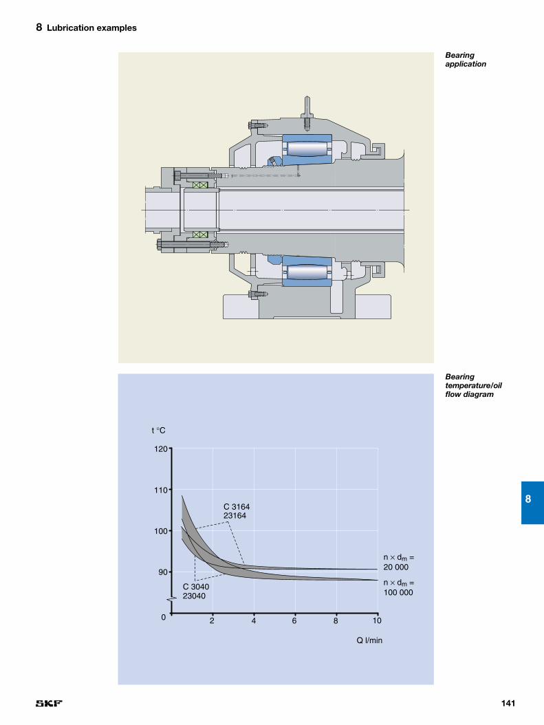
141
8
8 Lubrication examples
Bearing application
Bearing temperature/oilflow diagram
n × dm = 20 000
n × dm = 100 000
Q l/min
0
90
C 304023040
2
100
110
120
23164C 3164
4 6 8 10
t °C

142
8 Lubrication examples
Example 19
Drying cylinder with steam temperature 190 °C (374 °F)Machine dataPaper qualities board, linerRoll position dryer sectionPaper speed 400–1 300 m/min (1 320–4 270 fpm)
Operating conditions for the bearingsRotational speed 5–30 % of the speed ratingAmbient temperature 100 °C (212 °F)Lubrication circulating oilOil viscosity ISO VG 220Oil inlet temperature 60 °C (140 °F)Journal insulation none
Lubrication guidelinesAs drying cylinder bearings rotate at relatively low speeds and are subjected tohigh temperatures there will be metallic contact between rollers and raceways.This means that there is a risk of surface distress. To avoid this risk the circulat-ing oil should have efficient AW additives and a viscosity ratio κ according to theguidelines on page 207.
General guidelines, as outlined under “Oil lubrication” (➔ pages 95–97), shouldalso be taken into account.
Comments on the diagramBearing temperature depends on the bearing speed, applied load and externalcooling or heating of the bearing arrangement. Therefore, the calculated bearingtemperatures in the diagram are valid only when the bearing application andoperating conditions are similar to those indicated here.
The calculations for this diagram have been made using an SKF computerprogram to give the inner ring temperature. The load at each speed correspondsto the minimum recommended bearing life of 200 000 h.
An oil flow of 0,5 l/min, which is common in old machines, gives a bearingtemperature of around 155 °C.
At operating temperatures above 100 °C, it is not possible to fulfil the κ guide-lines and some mineral oils have shown a strong tendency to carbonise. There-fore the recommendation for such applications is to improve the lubrication conditions as much as practically possible.
The diagram shows that the influence of the oil quantity is considerable up to4 l/min, but after that scarcely anything is gained by an increased oil flow exceptfor large size bearings at high speeds.
The best action is to introduce efficient journal insulation which gives a bear-ing temperature of about 95–100 °C (➔ example 20, pages 144–145). Changingto a synthetic oil is also beneficial.

143
8
8 Lubrication examples
Bearing application
Bearing temperature/oilflow diagram
n × dm = 20 000
n × dm = 100 000
Q l/min
0 2
120
130
140
C 304023040
4 6 8 10
t °C
150
160
23164C 3164

144
8 Lubrication examples
Example 20
Drying cylinder with steam temperature 190 °C (374 °F)Machine dataPaper qualities board, linerRoll position dryer sectionPaper speed 400–1 300 m/min (1 320–4 270 fpm)
Operating conditions for the bearingsRotational speed 5–30 % of the speed ratingAmbient temperature 100 °C (212 °F)Lubrication circulating oilOil viscosity ISO VG 220Oil inlet temperature 60 °C (140 °F)Journal insulation yes
Lubrication guidelinesAs drying cylinder bearings rotate at relatively low speeds and are subjected tohigh temperatures there will be metallic contact between rollers and raceways.This means that there is a risk of surface distress. To avoid this risk the circulat-ing oil should have efficient AW additives and a viscosity ratio k according to theguidelines on page 207.
General guidelines, as outlined under “Oil lubrication” (➔ pages 95–97), shouldalso be taken into account.
Comments on the diagramBearing temperature depends on the bearing speed, applied load and externalcooling or heating of the bearing arrangement. Therefore, the calculated bearingtemperatures in the diagram are valid only when the bearing application andoperating conditions are similar to those indicated here.
The calculations for this diagram have been made using an SKF computerprogram to give the inner ring temperature. The load at each speed correspondsto the minimum recommended bearing life of 200 000 h.
An oil flow of 0,5 l/min was common in the early machines with insulated jour-nals. Such an oil flow gives a bearing temperature of around 115 °C. The aim forthis application is to find the optimum oil flow which gives a bearing temperatureof around 95–100 °C.
The diagram shows that the influence of the oil quantity is considerable up to3–4 l/min, but after that scarcely anything is gained by an increased oil flowexcept for large size bearings at high speeds.
If an ISO VG 320 oil is used instead the bearing temperature will increase a little but because the viscosity ratio κ would be higher than when using an ISO VG 220 oil its use will be beneficial.

145
8
8 Lubrication examples
Bearing application
Bearing temperature/oilflow diagram
n × dm = 100 000
Q l/min
n × dm = 20 000
0
90
2
100
110
120
C 304023040
23164C 3164
4 6 8 10
t °C
130

146
8 Lubrication examples
Example 21
Yankee suction press roll (oil)Machine dataPaper qualities board, tissueRoll position dryer sectionPaper speed 400–2 200 m/min (1 320–7 220 fpm)
Operating conditions for the bearingsRotational speed 10–200 % of the speed ratingAmbient temperature 45 °C (113 °F)Lubrication circulating oilOil viscosity ISO VG 220Oil inlet temperature 45 °C (113 °F)
Lubrication guidelinesAs suction roll bearings are large and sometimes rotate at very high speedsthere is a risk of smearing. To avoid smearing, the oil should have EP additivesand the viscosity ratio κ should be according to the guidelines on page 207.
General guidelines, as outlined under “Oil lubrication” (➔ pages 95–97), shouldalso be taken into account.
Comments on the diagramBearing temperature depends on the bearing speed, applied load and externalcooling or heating of the bearing arrangement. Heat transfer from the housing,shaft and the foundation is largely dependent on the bearing application andoperating conditions. Therefore, the oil flow in the diagram is valid only when thebearing application and operating conditions are similar to those indicated here.
The calculations for this diagram have been made using an SKF computerprogram to give the outer ring temperature. The load at each speed correspondsto the minimum recommended bearing life of 120 000 h.
The oil flow in the diagram is based on an ISO VG 220 oil and selected to fulfil two criteria: the κ guidelines and a bearing operating temperature of 75 °C.If an oil with lower viscosity than ISO VG 220 is used for these bearings then theoil flows must be increased. A thicker oil, e.g. ISO VG 320, is advantageous and will improve the lubrication conditions, but the bearing temperature will increasea little.
Note that the diagram shows minimum oil flow. Slightly higher oil flow valuesare acceptable and beneficial in most cases.

147
8
8 Lubrication examples
Bearing application
Oil flows for bearing temperat-ures 75 °C (167 °F)
23080
23160
230/500239/530
239602306023980
239/63023180
230/600239/710
0 100 000
5
10
15
300 000 500 000
Q l/min
20
25
n × dm

148
8 Lubrication examples
Example 22
Yankee cylinder with steam temperature 140 °C(284 °F) (oil bath)Machine dataPaper qualities board (old machines)Roll position dryer sectionPaper speed 100–150 m/min (330–490 fpm)
Operating conditions for the bearingsRotational speed 1–2 % of the speed ratingAmbient temperature 60 °C (140 °F)Lubrication oil bathOil viscosity ISO VG 220–1 500Journal insulation none
Lubrication guidelinesAs Yankee cylinder bearings in this example rotate at very low speeds and aresubjected to high temperatures there will be metallic contact between rollers andraceways. This means that there is a risk of surface distress. To avoid this riskthe lubricating oil should have efficient AW additives and a viscosity ratio κaccording to the guidelines on page 207.
A synthetic oil is recommended, because mineral oils are not suitable at tem-peratures above 120 °C.
General guidelines, as outlined under “Oil lubrication” (➔ pages 95–97), shouldalso be taken into account.
Comments on the diagramBearing temperature depends on the bearing speed, applied load and externalcooling or heating of the bearing arrangement. Therefore, the calculated bearingtemperatures in the diagram are valid only when the bearing application andoperating conditions are similar to those indicated here.
The calculations for this diagram have been made using an SKF computerprogram to give the inner ring temperature. The load at each speed correspondsto the minimum recommended bearing life of 200 000 h. Note that the bearingtemperature is lower at “high” speeds than at low speeds. The reason is that theincrease in cooling via the rotating journal is higher than the increase in heatgeneration in the bearing.
At operating temperatures above 100 °C, it is not possible to fulfil the κ guide-lines with commonly used ISO VG 220 oils.
The recommendation for this application is to improve the lubrication condi-tions as much as practically possible. The best remedy is to introduce an efficientjournal insulation in combination with circulating oil lubrication. This gives abearing temperature of 85 °C (➔ example 24, pages 152–153). Changing to anoil with higher viscosity than used for circulation systems is also beneficial.

149
8
8 Lubrication examples
Bearing application
Bearing temperature/speedfactor diagram
0
120
2 000
130
140
150
6 000 10 000
ISO VG 220
ISO VG 1000
23060
23180
2316023080
C 3060
C 3180
C 3160C 3080
t °C
n × dm

150
8 Lubrication examples
Example 23
Yankee cylinder with steam temperature 140 °C (284 °F)Machine dataPaper qualities board, tissueRoll position dryer sectionPaper speed 100–1 000 m/min (330–3 300 fpm)
Operating conditions for the bearingsRotational speed 1–20 % of the speed ratingAmbient temperature 60 °C (140 °F)Lubrication circulating oilOil viscosity ISO VG 320 or 460Oil inlet temperature 45 °C (113 °F)Journal insulation none
Lubrication guidelinesAs Yankee cylinder bearings rotate at low speeds and are subjected to high temperatures there will be metallic contact between rollers and raceways. Thismeans that there is a risk of surface distress. To avoid this risk the circulating oil should have efficient AW additives and a viscosity ratio κ according to theguidelines on page 207.
General guidelines, as outlined under “Oil lubrication” (➔ pages 95–97), shouldalso be taken into account.
Comments on the diagramBearing temperature depends on the bearing speed, applied load and externalcooling or heating of the bearing arrangement. Therefore, the calculated bearingtemperatures in the diagram are valid only when the bearing application andoperating conditions are similar to those indicated here.
The calculations for this diagram are made at SKF with a computer programthat indicates the inner ring temperature. The load at each speed corresponds tothe minimum recommended bearing life of 200 000 h.
The bearing operating temperature will be above 110 °C also at very high oilflows. At operating temperatures above 100 °C, it is not possible to fulfil the κguidelines and some mineral oils have shown a strong tendency to carbonise.Therefore the recommendation for such applications is to improve the lubricationconditions as much as practically possible.
The diagram shows that the influence of the oil quantity is considerable up to4–5 l/min, but after that scarcely anything is gained by an increased oil flowexcept for large size bearings at high speeds.
The best action is to introduce efficient journal insulation which gives a bear-ing temperature of about 80–85 °C (➔ example 24). Changing to a synthetic oil is also beneficial.

151
8
8 Lubrication examples
Bearing application
Bearing temperature/oilflow diagram
n × dm = 40 000
Q l/min
n × dm = 5 000
231/670
0 4
110
120
130
C 306823068
8 12 16 20
t °C
140

152
8 Lubrication examples
Example 24
Yankee cylinder with steam temperature 140 °C (284 °F)Machine dataPaper qualities board, tissueRoll position dryer sectionPaper speed 400–1 000 m/min (1 320–3 300 fpm)
Operating conditions for the bearingsRotational speed 5–20 % of the speed ratingAmbient temperature 60 °C (140 °F)Lubrication circulating oilOil viscosity ISO VG 320 or 460Oil inlet temperature 45 °C (113 °F)Journal insulation yes
Lubrication guidelinesAs Yankee cylinders bearings rotate at relatively low speeds and are subjectedto high temperatures there will be metallic contact between rollers and raceways.This means that there is a risk of surface distress. To avoid this risk the circulatingoil should have efficient AW additives and a viscosity ratio κ according to theguidelines on page 207.
General guidelines, as outlined under “Oil lubrication” (➔ pages 95–97), shouldalso be taken into account.
Comments on the diagramBearing temperature depends on the bearing speed, applied load and externalcooling or heating of the bearing arrangement. Therefore, the calculated bearingtemperatures in the diagram are valid only when the bearing application andoperating conditions are similar to those indicated here.
The calculations for this diagram have been made using an SKF computerprogram to give the inner ring temperature. The load at each speed correspondsto the minimum recommended bearing life of 200 000 h.
An oil flow of 1–2 l/min was sometimes used in the early machines with in-sulated journals. Such an oil flow gives a bearing temperature around 90 °C.
The aim for this application is to find the optimum oil flow which gives a bear-ing temperature of around 80–85 °C.
The diagram shows that the influence of the oil quantity is considerable up to4–6 l/min, but after that scarcely anything is gained by an increased oil flowexcept for large size bearings at high speeds.

153
8
8 Lubrication examples
Bearing application
Bearing temperature/oilflow diagram
n × dm = 50 000
Q l/min
n × dm = 10 000
231/670
0
80
C 306823068
4
90
100
110
8 12 16 20
t °C

154
8 Lubrication examples
Example 25
Yankee cylinder with steam temperature 165 °C (329 °F)Machine dataPaper qualities tissue, boardRoll position dryer sectionPaper speed 400–1 500 m/min (1 320–4 920 fpm)
Operating conditions for the bearingsRotational speed 5–30 % of the speed ratingAmbient temperature 60 °C (140 °F)Lubrication circulating oilOil viscosity ISO VG 320 or 460Oil inlet temperature 45 °C (113 °F)Journal insulation none
Lubrication guidelinesAs Yankee cylinder bearings rotate at relatively low speeds and are subjected tohigh temperatures there will be metallic contact between rollers and raceways.This means that there is a risk of surface distress. To avoid this risk the circulatingoil should have efficient AW additives and a viscosity ratio κ according to theguidelines on page 207.
General guidelines, as outlined under “Oil lubrication” (➔ pages 95–97), shouldalso be taken into account.
Comments on the diagramBearing temperature depends on the bearing speed, applied load and externalcooling or heating of the bearing arrangement. Therefore, the calculated bearingtemperatures in the diagram are valid only when the bearing application andoperating conditions are similar to those indicated here.
The calculations for this diagram have been made using an SKF computerprogram to give the inner ring temperature. The load at each speed correspondsto the minimum recommended bearing life of 200 000 h.
An oil flow of 2 l/min, which is sometimes used for old machines, gives a bear-ing temperature of around 135 °C.
At operating temperatures above 100 °C, it is not possible to fulfil the κ guide-lines and some mineral oils have shown a strong tendency to carbonise. There-fore the recommendation for such applications is to improve the lubrication conditions as much as practically possible.
The diagram shows that the influence of the oil quantity is considerable up to5–7 l/min, but after that scarcely anything is gained by an increased oil flowexcept for large size bearings at high speeds.
The best action is to introduce efficient journal insulation which gives a bearing temperature of about 90 °C (➔ example 26, pages 156–157). Changingto a synthetic oil is also beneficial.

155
8
8 Lubrication examples
Bearing application
Bearing temperature/oilflow diagram
n × dm = 70 000
Q l/min
n × dm = 10 000
0
120
130
4
C 306823068
8 12 16 20
231/670
t °C
140
150

156
8 Lubrication examples
Example 26
Yankee cylinder with steam temperature 165 °C (329 °F)Machine dataPaper qualities tissue, boardRoll position dryer sectionPaper speed 400–2 200 m/min (1 320–7 220 fpm)
Operating conditions for the bearingsRotational speed 5–35 % of the speed ratingAmbient temperature 60 °C (140 °F)Lubrication circulating oilOil viscosity ISO VG 320 or 460Oil inlet temperature 45 °C (113 °F)Journal insulation yes
Lubrication guidelinesAs Yankee cylinder bearings rotate at relatively low speeds and are subjected tohigh temperatures there will be metallic contact between rollers and raceways.This means that there is a risk of surface distress. To avoid this risk the circulat-ing oil should have efficient AW additives and a viscosity ratio κ according to theguidelines on page 207.
General guidelines, as outlined under “Oil lubrication” (➔ pages 95–97), shouldalso be taken into account.
Comments on the diagramBearing temperature depends on the bearing speed, applied load and externalcooling or heating of the bearing arrangement.Therefore, the calculated bearingtemperatures in the diagram are valid only when the bearing application andoperating conditions are similar to those indicated here.
The calculations for this diagram have been made using an SKF computerprogram to give the inner ring temperature. The load at each speed correspondsto the minimum recommended bearing life of 200 000 h.
An oil flow of 2 l/min was sometimes used in the early machines with in-sulated journals. Such an oil flow gives a bearing temperature around 100 °C. If the bearing operating temperature is above 100 °C it is impossible to fulfil the κ guidelines. The aim for this application is to find the optimum oil flow whichgives a bearing temperature below 90 °C.
The diagram shows that the influence of the oil quantity is considerable up to5–7 l/min, but after that scarcely anything is gained by an increased oil flowexcept for large size bearings at high speeds.

157
8
8 Lubrication examples
Bearing application
Bearing temperature/oilflow diagram
n × dm = 100 000
Q l/min
n × dm = 10 000
231/670
0
80
4
90
100
110
C 306823068
8 12 16 20
t °C
120

158
8 Lubrication examples
Example 27
Yankee cylinder with steam temperature 190 °C (374 °F) Machine dataPaper qualities tissue, boardRoll position dryer sectionPaper speed 400–1 500 m/min (1 320–4 920 fpm)
Operating conditions for the bearingsRotational speed 5–30 % of the speed ratingAmbient temperature 60 °C (140 °F)Lubrication circulating oilOil viscosity ISO VG 320 or 460Oil inlet temperature 45 °C (113 °F)Journal insulation none
Lubrication guidelinesAs Yankee cylinder bearings rotate at relatively low speeds and are subjected tohigh temperatures there will be metallic contact between rollers and raceways.This means that there is a risk of surface distress. To avoid this risk the circulat-ing oil should have efficient AW additives and a viscosity ratio κ according to theguidelines on page 207.
General guidelines, as outlined under “Oil lubrication” (➔ pages 95–97), shouldalso be taken into account.
Comments on the diagramBearing temperature depends on the bearing speed, applied load and externalcooling or heating of the bearing arrangement. Therefore, the calculated bearingtemperatures in the diagram are valid only when the bearing application andoperating conditions are similar to those indicated here.
The calculations for this diagram have been made using an SKF computerprogram to give the inner ring temperature. The load at each speed correspondsto the minimum recommended bearing life of 200 000 h.
An oil flow of 2–3 l/min, which is common in old machines, gives a bearingtemperature of around 155 °C.
At operating temperatures above 100 °C, it is not possible to fulfil the κ guide-lines and some mineral oils have shown a strong tendency to carbonise. There-fore the recommendation for such applications is to improve the lubrication conditions as much as practically possible.
The diagram shows that the influence of the oil quantity is considerable up to6–8 l/min, but after that scarcely anything is gained by an increased oil flowexcept for large size bearings at high speeds.
The best action is to introduce efficient journal insulation which gives a bearing temperature of about 95 °C (➔ example 28, pages 160–161). Changingto a synthetic oil is also beneficial.

159
8
8 Lubrication examples
Bearing application
Bearing temperature/oilflow diagram
n × dm = 70 000
Q l/min
n × dm = 10 000
231/670
0
130
4
140
150
160
C 306823068
8 12 16 20
t °C
170

160
8 Lubrication examples
Yankee cylinder with steam temperature 190 °C (374 °F) Machine dataPaper qualities tissue, boardRoll position dryer sectionPaper speed 400–2 200 m/min (1 320–7 220 fpm)
Operating conditions for the bearingsRotational speed 5–35 % of the speed ratingAmbient temperature 60 °C (140 °F)Lubrication circulating oilOil viscosity ISO VG 320 or 460Oil inlet temperature 45 °C (113 °F)Journal insulation yes
Lubrication guidelinesAs Yankee cylinder bearings rotate at relatively low speeds and are subjected tohigh temperatures there will be metallic contact between rollers and raceways.This means that there is a risk of surface distress. To avoid this risk the circulat-ing oil should have efficient AW additives and a viscosity ratio κ according to theguidelines on page 207.
General guidelines, as outlined under “Oil lubrication” (➔ pages 95–97), shouldalso be taken into account.
Comments on the diagramBearing temperature depends on the bearing speed, applied load and externalcooling or heating of the bearing arrangement. Therefore, the calculated bearingtemperatures in the diagram are valid only when the bearing application andoperating conditions are similar to those indicated here.
The calculations for this diagram have been made using an SKF computerprogram to give the inner ring temperature. The load at each speed correspondsto the minimum recommended bearing life of 200 000 h.
An oil flow of 2–3 l/min was common in the early machines with insulated journals. Such an oil flow gives a bearing temperature of around 110 °C. If thebearing operating temperature is above 100 °C it is impossible to fulfil the κguidelines. The aim for this application is to find the optimum oil flow whichgives a bearing temperature of 90–95 °C.
The diagram shows that the influence of the oil quantity is considerable up to6–8 l/min, but after that scarcely anything is gained by an increased oil flowexcept for large size bearings at high speeds.
Example 28

161
8
8 Lubrication examples
Bearing application
Bearing temperature/oilflow diagram
n × dm = 10 000
n × dm = 100 000
Q l/min
231/670
0
90
4
100
110
120
C 306823068
8 12 16 20
t °C
130

162
8 Lubrication examples
Example 29
Paper guide roll (grease)Machine dataPaper qualities board, liner, fine, newsprintRoll position after dryer sectionPaper speed 100–1 000 m/min (330–3 300 fpm)
Operating conditions for the bearingsRotational speed 5–35 % of the speed ratingAmbient temperature 45 °C (113 °F)Lubrication greaseBase oil viscosity 175 mm2/s at 40 °C
Lubrication guidelinesSKF experience is that a grease with a base oil viscosity of minimum 175 mm2/shas good lubrication performance in this position. Operating conditions for greaselubricated bearings in the forming section are more severe than in this example.Therefore, the grease selected for the forming section can also be used here.
General guidelines, as outlined under “Grease lubrication” (➔ pages 91–94),should also be taken into account.
Comments on the diagramBearing temperature depends on the bearing speed, applied load and externalcooling or heating of the bearing arrangement. Heat transfer from the housing,shaft and the foundation is largely dependent on the bearing application andoperating conditions. Therefore, the calculated bearing temperatures in thisexample are valid only when the bearing application and operating conditionsare similar to those indicated here.
The calculations for this diagram have been made using an SKF computerprogram to give the outer ring temperature at different speeds. The load at eachspeed corresponds with the recommended bearing life of 120 000 h.
The highest bearing temperature shown in the diagram is 75 °C as it is cus-tomary to use oil lubrication at higher temperatures.

163
8
8 Lubrication examples
23248 23240 23230 2231622320
0 20 000
60
70
80
60 000 100 000
t °C2322022330C 2316C 2320
n × dm
Bearing application
Bearing temperature/speedfactor diagram

164
8 Lubrication examples
Example 30
Paper guide roll (oil)Machine dataPaper qualities allRoll position after dryer sectionPaper speed 400–2 200 m/min (1 320–7 220 fpm)
Operating conditions for the bearingsRotational speed 20–60 % of the speed ratingAmbient temperature 45 °C (113 °F)Lubrication circulating oilOil viscosity ISO VG 220Oil inlet temperature 50 °C (122 °F)
Lubrication guidelinesPaper guide roll bearings have better operating conditions than drying cylinderbearings which are lubricated from the same circulating oil system. Therefore,the lubricant properties should be based on the operating conditions for dryingcylinder bearings. However, the paper guide roll bearings should have an oil flowgiving a viscosity ratio κ according to the guidelines on page 207.
General guidelines, as outlined under “Oil lubrication” (➔ pages 95–97), shouldalso be taken into account.
Comments on the diagramBearing temperature depends on the bearing speed, applied load and externalcooling or heating of the bearing arrangement. Heat transfer from the housing,shaft and the foundation is largely dependent on the bearing application andoperating conditions. Therefore, the calculated bearing temperatures in the diagram are valid only when the bearing application and operating conditionsare similar to those indicated here.
The calculations for this diagram have been made using an SKF computerprogram to give the outer ring temperature. The load at each speed correspondsto the recommended bearing life of 200 000 h. The oil flow in the diagram isbased on an ISO VG 220 oil and selected to fulfil two criteria: the κ guidelinesand a bearing operating temperature of 75 °C.
If an oil with lower viscosity than ISO VG 220 is used the flow must be in-creased in order to reach the same κ value. A thicker oil, e.g. ISO VG 320, isadvantageous and will improve the lubrication conditions, but the bearing tem-perature will increase a little.
Note that the diagram shows minimum oil flow. Slightly higher oil flow valuesare acceptable and beneficial in most cases.

165
8
8 Lubrication examples
23240
2323022340
22330
22320
22311
23220
23244
23248
0 50 000
2
4
150 000 250 000
Q l/min
6
8
n × dm
C 2320
Bearing application
Oil flows for bearing temperat-ure 75 °C (167 °F)

166
8 Lubrication examples
Example 31
Calender roll, plain, unheated (oil bath)Machine dataPaper qualities board, fineRoll position machine calender (old machines)Paper speed 100–700 m/min (330–2 300 fpm)
Operating conditions for the bearingsRotational speed 5–40 % of the speed ratingAmbient temperature 45 °C (113 °F)Lubrication oil bathOil viscosity ISO VG 220
Lubrication guidelinesThe bearings in this example have relatively good lubrication conditions. How-ever, bearings running at low speeds will have metal-to-metal contact betweenrollers and raceways. This gives a risk of surface distress. To avoid this risk thelubricating oil should have efficient AW additives and a viscosity ratio κ accord-ing to the guidelines on page 207.
General guidelines, as outlined under “Oil lubrication” (➔ pages 95–97), shouldalso be taken into account.
Comments on the diagramBearing temperature depends on the bearing speed, applied load and externalcooling or heating of the bearing arrangement. Therefore, the calculated bearingtemperatures in the diagram are valid only when the bearing application andoperating conditions are similar to those indicated here.
The calculations for this diagram have been made using an SKF computerprogram to give the outer ring temperature. The load at each speed correspondsto the minimum recommended bearing life of 120 000 h.
In this example oil bath lubrication fulfils the SKF lubrication guidelines regard-ing the viscosity ratio κ but not the guidelines for lubricant cleanliness. Therefore,the recommendation for this application is to improve the lubricant cleanliness.
Oil cleanliness can be improved by various means e.g. by improved seals forthe bearing housing, decreased time between the oil changes or the introductionof an oil circulation system with filters and water extractors. However, the costfor these can sometimes be higher than the gains from increased machineavailability and decreased bearing consumption.

167
8
8 Lubrication examples
230302304023060C 3040C 3060
231302314023160C 3130C 3140C 3160
2404024060
232402326023280
0
50
40 000
60
70
80
90
80 000 120 000
t °C
100
n × dm
Bearing application
Bearing temperature/speedfactor diagram

168
8 Lubrication examples
Example 32
Calender roll, plain, unheated (oil)Machine dataPaper qualities board, liner, fine, newsprintRoll position machine calenderPaper speed 400–2 000 m/min (1 310–6 550 fpm)
Operating conditions for the bearingsRotational speed 20–130 % of the speed ratingAmbient temperature 45 °C (113 °F)Lubrication circulating oilOil viscosity ISO VG 220Oil inlet temperature 50 °C (122 °F)
Lubrication guidelinesThe guidelines below are based on a large size bearing rotating at high speed,because these bearings have the most demanding operating conditions.
Large bearings rotating at high speed are subjected to a risk of smearing. Toavoid smearing, the oil should have EP additives and the viscosity ratio κ shouldbe according to the guidelines on page 207.
General guidelines, as outlined under “Oil lubrication” (➔ pages 95–97), shouldalso be taken into account.
Comments on the diagramBearing temperature depends on the bearing speed, applied load and externalcooling or heating of the bearing arrangement. Heat transfer from the housing,shaft and the foundation is largely dependent on the bearing application andoperating conditions. Therefore, the oil flow in the diagram is valid only when thebearing application and operating conditions are similar to those indicated here.
The calculations for this diagram have been made using an SKF computerprogram to give the outer ring temperature. The load at each speed correspondsto the minimum recommended bearing life of 120 000 h.
The oil flow in the diagram is based on an ISO VG 220 oil and selected to fulfiltwo criteria: the κ guidelines and a bearing operating temperature of 75 °C.
If an oil with lower viscosity than ISO VG 220 is used for these bearings the oilflows must be increased. An oil with higher viscosity is to advantage and will im-prove the lubrication conditions, but the bearing temperature will increase a little.
Note that the diagram shows minimum oil flow. Slightly higher oil flow valuesare acceptable and beneficial in most cases.

169
8
8 Lubrication examples
100 000 200 000 300 000
Q l/min
n × dm
23080
23240
2404023160
23140
C 3080
C 3160C 3140
24060
23040
2326023180
C 3180
23060C 3040C 3060
23280
232/500
0
5
10
15
20
25
Bearing application
Oil flows for bearing temperat-ure 75 °C (167 °F)

170
8 Lubrication examples
Example 33
Calender roll with steam temperature 140 °C (284 °F)Machine dataPaper qualities board, liner, fine, newsprintRoll position machine calenderPaper speed 400–2 000 m/min (1 310–6 550 fpm)
Operating conditions for the bearingsRotational speed 20–110 % of the speed ratingAmbient temperature 45 °C (113 °F)Lubrication circulating oilOil viscosity ISO VG 220Oil inlet temperature 50 °C (122 °F)Journal insulation bore and end face
Lubrication guidelinesAs large calender roll bearings sometimes rotate at high speeds there is a risk of smearing. To avoid smearing SKF usually recommends the use of an oil withefficient EP additives and oil flows giving a viscosity ratio κ according to the guide-lines on page 207. However, with the above operating conditions the bearingtemperature will be too high for EP additives and accordingly oils with efficientAW additives have to be used.
General guidelines, as outlined under “Oil lubrication” (➔ pages 95–97), shouldalso be taken into account.
Comments on the diagramBearing temperature depends on the bearing speed, applied load and externalcooling or heating of the bearing arrangement. Therefore, the calculated bearingtemperatures in this example are valid only when the bearing application andoperating conditions are similar to those indicated here.
The calculations for this diagram have been made using an SKF computerprogram to give the inner ring temperature. The load at each speed correspondsto the minimum recommended bearing life of 120 000 h.
At high speeds it is not possible to fulfil the κ guidelines and accordingly thebest possible lubrication conditions should be aimed for, especially since EPadditives cannot be used.
At low speeds the diagram shows that the influence of the oil quantity onbearing temperature is considerable up to 2–4 l/min, but after that scarcely anything is gained by an increased oil flow. For large size bearings rotating athigh speeds the diagram shows that the influence of the oil quantity is con-siderable up to about 8 l /min.
An oil with higher viscosity is beneficial and will improve the lubrication con-ditions, but the bearing temperature will increase a little.

171
8
8 Lubrication examples
n × dm = 75 000
n × dm = 275 000
Q l/min
0
80
2
100
120
140
23040C 3040
23280
4 6 8 10
t °C
160
Bearing application
Bearing temperature/oilflow diagram

172
8 Lubrication examples
Calender roll with steam/oil temperature 175 °C (347 °F)Machine dataPaper qualities board, liner, fine, newsprintRoll position machine/soft calenderPaper speed 400–2 000 m/min (1 310–6 550 fpm)
Operating conditions for the bearingsRotational speed 25–150 % of the speed ratingAmbient temperature 50 °C (122 °F)Lubrication circulating oilOil viscosity ISO VG 320Oil inlet temperature 40 °C (104 °F)Journal insulation bore and end face
Lubrication guidelinesAs large calender roll bearings sometimes rotate at high speeds there is a risk of smearing. To avoid smearing SKF usually recommends the use of an oil withefficient EP additives and oil flows giving a viscosity ratio κ according to theguidelines on page 207. However, with the above operating conditions the bear-ing temperature will be too high for EP additives and accordingly oils with effi-cient AW additives have to be used.
General guidelines, as outlined under “Oil lubrication” (➔ pages 95–97), shouldalso be taken into account.
Comments on the diagramBearing temperature depends on the bearing speed, applied load and externalcooling or heating of the bearing arrangement. Therefore, the calculated bearingtemperatures in this example are valid only when the bearing application andoperating conditions are similar to those indicated here.
The calculations for this diagram have been made using an SKF computerprogram to give the inner ring temperature. The load at each speed correspondsto the minimum recommended bearing life of 120 000 h.
At high speeds it is not possible to fulfil the κ guidelines on page 207, andaccordingly the best possible lubrication conditions should be aimed for, especially since EP additives cannot be used.
At low speeds the diagram shows that the influence of the oil quantity onbearing temperature is considerable up to 3–6 l/min, but after that scarcely any-thing is gained by an increased oil flow. For large size bearings rotating at highspeeds the diagram shows that the influence of the oil quantity is considerableup to about 12 l /min.
An oil with higher viscosity is beneficial and will improve the lubrication condi-tions, but the bearing temperature will increase a little.
Example 34

173
8
8 Lubrication examples
n × dm = 50 000
n × dm = 300 000
0
80
23156
232/670C 3156
4
100
120
140
8 12 16 20
23156
232/670
C 3156
t °C
160
180
Q l/min
Bearing application
Bearing temperature/oilflow diagram

174
8 Lubrication examples
Example 35
Calender roll with oil temperature 250 °C (482 °F)Machine dataPaper qualities board, liner, fine, newsprintRoll position machine/soft calenderPaper speed 400–2 000 m/min (1 310–6 550 fpm)
Operating conditions for the bearingsRotational speed 25–150 % of the speed ratingAmbient temperature 50 °C (122 °F)Lubrication circulating oilOil viscosity ISO VG 320Oil inlet temperature 40 °C (104 °F)Journal insulation bore and end face
Lubrication guidelinesAs large calender roll bearings sometimes rotate at high speeds there is a risk of smearing. To avoid smearing SKF usually recommends the use of an oil withefficient EP additives and oil flows giving a viscosity ratio κ according to theguidelines on page 207. However, with the above operating conditions the bear-ing temperature will be too high for EP additives and accordingly oils with effi-cient AW additives have to be used.
General guidelines, as outlined under “Oil lubrication” (➔ pages 95–97), shouldalso be taken into account.
Comments on the diagramBearing temperature depends on the bearing speed, applied load and externalcooling or heating of the bearing arrangement. Therefore, the calculated bearingtemperatures in this example are valid only when the bearing application andoperating conditions are similar to those indicated here.
The calculations for this diagram have been made using an SKF computerprogram to give the inner ring temperature. The load at each speed correspondsto the minimum recommended bearing life of 120 000 h.
Except for small bearings rotating at low speeds it is not possible to fulfil the κ guidelines on page 207. Accordingly the best possible lubrication conditionsshould be aimed for.
At low speeds the diagram shows that the influence of the oil quantity onbearing temperature is considerable up to 4–6 l/min, but after that scarcely anything is gained by an increased oil flow. For large size bearings rotating athigh speeds the diagram shows that the influence of the oil quantity is con-siderable up to about 16 l /min.
An oil with higher viscosity is beneficial and will improve the lubrication conditions, but the bearing temperature will increase a little.

175
8
8 Lubrication examples
n × dm = 300 000
n × dm = 50 000
Q l/min
0
100
23156
23292232/670
C 3156
4
120
140
160
8 12 16 20
23156
23292
232/670
C 3156
t °C
180
200
Bearing application
Bearing temperature/oilflow diagram

176
8 Lubrication examples
Example 36
Reel drum (grease)Machine dataPaper qualities allRoll position reelerPaper speed 100–600 m/min (330–1 970 fpm)
Operating conditions for the bearingsRotational speed 5–15 % of the speed ratingAmbient temperature 35 °C (95 °F)Lubrication greaseBase oil viscosity 175 mm2/s at 40 °C
Lubrication guidelinesSKF experience is that a grease with a base oil viscosity of minimum 175 mm2/shas good lubrication performance in this position.
The same grease as is used in the forming section can be used in this applica-tion, because the basic demands are the same and the special demands suchas those for rust protection are higher in the forming section.
General guidelines, as outlined under “Grease lubrication” (➔ pages 91–94),should also be taken into account.
Comments on the diagramBearing temperature depends on the bearing speed, applied load and externalcooling or heating of the bearing arrangement. Heat transfer from the housing,shaft and the foundation is largely dependent on the bearing application andoperating conditions. Therefore, the calculated bearing temperatures in the diagram are valid only when the bearing application and operating conditionsare similar to those indicated here.
The calculations for this diagram have been made using an SKF computerprogram to give the outer ring temperature. The load at each speed correspondsto the minimum recommended bearing life of 120 000 h. The highest bearingtemperature shown in the diagram is 75 °C as it is customary to use oil lubrica-tion at higher temperatures.

177
8
8 Lubrication examples
23160 23130C 3130
231402404024060
C 3160 C 3140
40 000 80 000 120 000
n × dm
0
50
60
70
80
t °C
Bearing application
Bearing temperature/speedfactor diagram

178
8 Lubrication examples
Example 37
Reel drum (oil)Machine dataPaper qualities allRoll position reelerPaper speed 400–2 200 m/min (1 310–7 220 fpm)
Operating conditions for the bearingsRotational speed 10–45 % of the speed ratingAmbient temperature 35 °C (95 °F)Lubrication circulating oilOil viscosity ISO VG 220Oil inlet temperature 45 °C (113 °F)
Lubrication guidelinesReel drum bearings have better operating conditions than drying cylinder bear-ings which often are lubricated from the same circulating oil system. Therefore,the lubricant properties should be based on the operating conditions for dryingcylinder bearings. However, the reel drum bearings should have an oil flow givinga viscosity ratio κ according to the guidelines on page 207.
General guidelines, as outlined under “Oil lubrication” (➔ pages 95–97), shouldalso be taken into account.
Comments on the diagramBearing temperature depends on the bearing speed, applied load and externalcooling or heating of the bearing arrangement. Heat transfer from the housing,shaft and the foundation is largely dependent on the bearing application andoperating conditions. Therefore, the calculated bearing temperatures in the diagram are valid only when the bearing application and operating conditionsare similar to those indicated here.
The calculations for this diagram have been made using an SKF computerprogram to give the outer ring temperature. The load at each speed correspondsto the minimum recommended bearing life of 120 000 h. The oil flow in the dia-gram is based on an ISO VG 220 oil and selected to fulfil two criteria: the κguidelines on page 207, and a bearing operating temperature of 75 °C.
If an oil with lower viscosity than ISO VG 220 is used the flow must beincreased in order to reach the same κ value.
An oil with higher viscosity is beneficial and will improve the lubrication con-ditions, but the bearing temperature will increase a little.
Note that the diagram shows minimum oil flow. Slightly higher oil flow valuesare acceptable and beneficial in most cases.

179
8
8 Lubrication examples
100 000 150 000 200 000
Q l/min
23130C 3130
23140C 3140
2316024040C 3160
24060
n × dm
0,5
0
1,0
1,5
2,0
2,5
Bearing application
Oil flows for bear-ing temperature75 °C (167 °F)

9 Maintenance
Maintenance philosophies . . . . . . . . . . . 182
Services and products supplied by SKF . . . . . . . . 184
Rebuild front side of dryingand Yankee cylinders to a CARB bearing arrangement . . . . . . . . . . . 185
Mounting and dismounting . . . . . . . . . . . . 186
Condition monitoring . . . . 193
Standstill precautions . . . . 196
How to store spare bearings . . . . . . . . . . . . . . . 197
How to avoid transport damage . . . . . . . . . . . . . . . 199
Failure modes . . . . . . . . . . 200
How to avoid surface damage . . . . . . . . . . . . . . . 207

Maintenance
181
Machine efficiencyThe most common way to expressmachine efficiency is the OME (Over-all Machine Efficiency) percentage (➔ fig , page 182). OME is normally65–95 %.
Paper mills and machine buildersare paying a lot of attention to theOME percentage, but also to paperspeed as total production is the resultof OME, trim width and paper speed.
Aims of maintenanceMaintenance certainly has some influence on paper quality and webbreaks, but the major aim of mainten-ance is to keep the machine runningwithout disturbances. Every unplanned
1
9 Maintenance
stop hour represents a production lossof at least 15 000 USD in a modernpaper machine. The profit loss perhour can be as high as 4 000 USD.
An unplanned stop does not reducethe need for planned stops. During aplanned stop, many other problemscan be dealt with at the same time.Unplanned stops are just some extrahours taken off the production capacity.
Increasing competition in the paper industry hasbrought high pressure on the cost of producingpaper. Many organizations were changed andmeasured against cost. This has caused a reduc-tion of capacity in all departments but, becausemaintenance is often regarded as a cost centre, it has suffered the most.
Therefore, over the last few years, too littleinvestment has been made in upgrades of mainten-ance technologies and competence. Maintenancehas become more and more reactive and resultedin an increase in unplanned stops. To improvethis situation, ways must be found to increasecapacity by improving overall equipment efficiency, without large capital expenditures.
9

Maintenance philosophiesReactive maintenanceIn the not so distant past the paperindustry’s approach to maintenancewas “fix it when it breaks”. Even todaysome mills still have this approach.With this type of maintenance, knownas reactive or “Run to failure”, actionis not taken until a problem results inmachine failure. The failure problemsoften cause costly secondary damagealong with unplanned downtime andexcessive maintenance cost.
Very often the failures are repeated,since often no real analysis about thereason for the failure is performed andtherefore no corrective actions wereperformed.
Preventive maintenancePreventive maintenance implies that a machine, or parts of a machine, isoverhauled on a regular basis regard-less of the condition of the parts. Theschedule is based on experience,which means that some problem areasget more service than others. Whilepreferable to reactive maintenance,preventive maintenance is costly be-cause of excessive planned downtimefrom unnecessary overhauls and thecost of replacing parts on the machinesoperating efficiently together with wornparts. Preventive maintenance leadsto fewer unplanned stops than withreactive maintenance but, some un-planned stops will always occur (➔ fig ). 2
As with reactive maintenance, thefailures very often are repeated, sinceoften no real analysis about the reasonfor the failure and therefore no correct-ive actions were performed.
Predictive maintenancePredictive maintenance is the process ofdetermining the condition of machinerywhile in operation. This is possible byusing vibration and lubrication analysis.This allows correction of problem com-ponents prior to failure. Predictive main-tenance not only helps plant personnelreduce the risk of catastrophic failure,but also allows them to order parts inadvance, schedule manpower and planother repairs during the downtime.
Many paper mills, with efficient predictive maintenance, have nounplanned stops caused by bearingproblems.
Root cause analysis is often notperformed.
1
182
9 MaintenanceMaintenance philosophies
Measure of OverallMachine Efficiency(OME)
Fig
% OME = (Uptime) × (Saleable product) × 100 %
Where
Annual hours the machine produces paperUptime =Annual available hours*
Saleable tonnageSaleable product =Produced tonnage
Failures inSwedish papermachines, estimated 1990
2Fig
All replaced bearings 100 %
95 % replaced as preventive maintenance
65 %Minor surface damage
– wear– corrosion– indentations– etc.
30 % “No”
damage
5 % replaced due tomalfunction orblocked bearing– flaked surfaces– heavy wear– “accidental failure”
* Excludes scheduled stops over 24 hours as well as holidays.
Source: TAPPI 0404-47 (1997)

183
9
9 MaintenanceMaintenance philosophies
Proactive maintenanceProactive maintenance is a furtherdevelopment of the predictive method.When a failure is detected, the reasonfor the failure is always analysed andcorrective actions are undertaken. Thiscontinuous improvement of the pro-cess, focussing on the weakest link inthe chain, makes it possible to eliminate
Maximum up timeversus different maintenancephilosophies
Development ofproduction andcost relative tomaintenancepractices
3Fig
1Diagram
unplanned stops and to have longertime between the planned stops andshorter stops than before. The smallimprovements eventually make it poss-ible to increase the production speedor load when needed.
The main difference between the maintenance philosophies can be seenin (➔ fig and diagram ).13
Corrective
Preventive
Predictive
Proactive
Maximum uptime
Scheduled Unscheduled Unscheduled Unscheduled Scheduleddown down down down down
Scheduled Unscheduled Scheduleddown down down
Scheduled Scheduleddown down
Scheduled Scheduleddown down
production
value
time
maintenance cost
component cost
Reactive:Main cost is atthe unplannedstops e.g. extrapersonnel, extraspare parts,repairs, waitinghours and over-time
Preventive:Main cost is theincreased per-sonnel and earlybearing changes
Predictive:Main cost isthe investmentin CM equip-ment andtraining byconsultants
Proactive:Cost reductionby outsourcingof mainten-ance staff and all theimprovements

5Fig
184
9 MaintenanceServices and products supplied by SKF
Services and productssupplied by SKFOver the years the SKF Trouble-FreeOperation (TFO) program has extendedbearing service life and increased pro-ductivity for bearing users by providinga full menu of bearing-related productsand services. The original TFO programfocused on education, with most of thework performed by the plant personnel.It also included services such as on-site trouble-shooting, application engin-eering support, bearing failure analysisand bearing rework services.
In recent years it has been a cleartrend in many industries to outsourcenon-core maintenance to the com-ponent suppliers to reduce the totalmaintenance costs. This is also thecase for paper mills. An increasingnumber of mills want the suppliers of machine elements like bearings,electrical motors, fans, pumps etc. totake over the responsibility of theseproducts.
In response to this trend, SKF hascombined its near-century of experi-ence with bearings, industry andadvanced capabilities in manufactur-ing and research to help customersincrease productivity.
For example, SKF now offers per-formance-based contracts, with a
guarantee of downtime reduction oruptime increase. The foundation forthe contract is the SKF ProactiveReliability Maintenance (PRM) process,a systematic method to benchmarkmachine efficiency and implementcorrective actions that decrease totallife cycle cost. It involves predictivemaintenance, root cause failure ana-lysis, corrective actions and ongoingoperational service measured accord-ing to Key Performance Indicators (KPI).
Furthermore SKF can offer serviceslike shaft alignment, lubricant analysis,condition monitoring services, bearingrefurbishment etc.
At SKF we also have put togetherthe industry’s most comprehensiveprogram of products for minimisingbearing failure. Among the productsare mounting and dismounting tools(➔ pages 186–192), condition mon-itoring equipment (➔ pages 193–195)and grease (➔ pages 92–93).
Some of these products and servicesare shown in the chain (➔ fig ). Thischain illustrates the connection be-tween machine reliability/availabilityand profitability. Remember that nochain is stronger than its weakest link!
5
Increased pro-fitability throughproducts and services suppliedby SKF
Mounting of bearings
SKF bearings
Mounting
Monitoring
Training
Bearing applications
Lubrication
Maintenance
Trouble shooting
Profitability
Reliability & Availability
4Fig

185
9
9 MaintenanceRebuild front side of drying and Yankee cylinders to a CARB bearing arrangement
Rebuild front side ofdrying and Yankeecylinders to a CARBbearing arrangementTo obtain all the benefits a CARBbearing arrangement can give, SKFnormally recommends the use of SKFCARB housings when rebuilding exist-ing machines. Reworking existinghousings can be as expensive as anew housing.
After many years in operation thebearing seatings of drying cylinderhousings may have extensive frettingcorrosion and be worn or oval. There-fore, in some cases the housing borehas to be reworked. When convertingfrom a rocker housing, a reworked hous-ing will not be as stable as a new one.
As CARB bearings follow the ISOstandard for dimensions, bearing C 3152 has the same boundary dimen-sions as spherical roller bearing 23152or cylindrical roller bearing N 3152. Ifthe existing housings are inspectedwith good results they may in manycases, perhaps somewhat modified,be used for CARB bearings when con-verting from other bearing types. If toomany modifications are required, thetotal cost for a rebuild can be as highas an investment in new housings.
When a rocker housing is modifiedto a fixed housing, it must be locked inall directions. This can be achieved bymodifying the housing according to
6Fig
7Fig
Modified rockerhousing
Axially locatedCARB outer ring
8Fig
A CARB bearinglubricated fromthe side
fig , depending on the design of theoriginal housing.
When rebuilding from spherical rollerbearings with an axially free outer ring,distance rings have to be used inorder to axially locate the CARB outerring (➔ fig ).
When the existing bearing is lubric-ated from the side (➔ fig ), it can bereplaced by a CARB bearing withoutany changes related to the lubrication.
If the existing bearing is lubricatedthrough the outer ring (➔ figs and
, page 58) the housing lubricationdesign must be changed when convert-ing to a CARB bearing. One way is todisplace the oil inlet to the outer sideof the bearing as for the SKF standardCARB housings. However, this requiresmodifications in order to ensure that nooil drains out without passing throughthe bearing. In some existing housingsthe diameter of the oil channels con-
1413
8
7
6

186
9 MaintenanceRebuild front side of drying and Yankee cylinders to a CARB bearing arrangement /Mounting and dismounting
To the left:SKF oil pumps andoil injectors
In the middle:SKF pullers
To the right:SKF heaters
Mounting and dismountingThe paper industry has always led the way by adopting the innovativemounting and dismounting methodsdeveloped by SKF. For modern bearingarrangements, the SKF oil injectionmethod has become industry standard.
SKF offers a complete range of toolsfor efficient bearing installation andremoval including
• oil pumps and oil injectors• hydraulic nuts HMV .. E• pullers• heaters
In order to facilitate mounting and dismounting most bearings in papermachines are fitted on tapered seat-ings. The use of adapter sleeves andwithdrawal sleeves has predominated,but the practice of mounting bearingsdirect on tapered journal seatings isbecoming more and more common.Running accuracy is improved and thecost of the sleeves is saved.
SKF Drive-up methodWhen mounting CARB and sphericalroller bearings with tapered bore theSKF Drive-up method is a more preciseand less subjective method than meas-uring the clearance reduction withfeeler gauges. Furthermore thismethod saves time.
Therefore, SKF strongly recommendsthe use of this method for mounting
necting the two sides of the bearing issmall and should be enlarged to makea high oil flow possible. The otheralternative is to displace the oil inlet tothe inner side of the bearing and plugthe oil channels connecting the twosides. Note that this modification mayinfluence the drainage capacity of thehousing.
When rebuilding to a CARB bearingarrangement, please contact SKF inorder to optimise the bearing arrange-ment for bearing function and totalcost.
SKF can offer a complete package forrebuilding existing housings to fixedCARB housings. This includes
• modification of existing housing• CARB bearing• mounting service

187
9
9 MaintenanceMounting and dismounting
larger bearings for example on dryingcylinders, suction rolls and press rolls.This method is preferable for smallerbearings as well. Especially for CARBbearings, the feeler gauge method isdifficult to apply.
SKF can supply suitable tools (➔ fig ) and mounting instructionsfor general applications as well asspecific applications like drying andYankee cylinders. SKF can also supplythe software program “SKF Drive-up”making it possible to make your owncalculations. Note that the drive-upvalues obtained are only valid for SKFbearings. For more information pleasecontact your local SKF sales unit.
A typical printout from the programis shown on page 190.
Sufficient clearance reductionA radial clearance reduction – ∆r – ofaround 0,0005 × d in paper machineapplications is sufficient to prevent theinner ring from working loose. Consider-able measuring uncertainty with feelergauges is the reason for the wide toler-ance range given in the General Cata-logue. Note that a bearing mounted tothe mean value according to the Gen-eral Catalogue gets somewhat greaterclearance reduction than 0,0005 × d.
Special situationsSometimes the bearings are mountedwith even greater clearance reductionthan recommended in the GeneralCatalogue. Common reasons are:
9
• Hollow shafts with very large bore,e.g. suction rolls
• Heavy loads (very few cases inpaper machines)
• Experiences from equal or similarapplications
One disadvantage with increasedclearance reduction is an increasedrisk of a fractured inner ring. There-fore, the following guidelines shouldbe applied for most unheated applica-tions:
SKF oil pump andhydraulic nut(HMV .. E) with dialindicator Dial indicators
9Fig
The equipment foraccurate drive-up
SKF hydraulic pump 729124 SRB (for nuts ≤ HMV 54 E)SKF hydraulic pump TMJL 100 SRB (for nuts ≤ HMV 92 E)SKF hydraulic pump TMJL 50 SRB (for nuts ≤ HMV 200 E)
dial indicatorSKF HMV E hydraulic nut

188
9 MaintenanceMounting and dismounting
• the clearance reduction ∆r for SKFstandard spherical roller bearingsshould not exceed 0,0007 × d
• the clearance reduction ∆r for SKFspherical roller bearings with casehardened inner rings (suffix HA3)should not exceed 0,0009 × d
If a greater clearance reduction than normal is chosen, do not forget tocheck if a bearing with greater clear-ance than Normal (C3, C4 ... ) is neededin order to avoid preload during opera-tion. For heated shafts – like dryingcylinders – greater clearance than normal is always needed.
Starting positionIn order to obtain reliable drive-upmeasurements, the influence of formerrors must be reduced to negligibleproportions. This can be done by driv-ing the bearing up, passing the inde-terminate zero position, to a startingposition that corresponds to a certainsmall initial interference (➔ fig ).Above this initial interference, reduc-tion in the radial internal clearancemay be regarded as being directly proportional to the axial drive-up.
Note that pressurised oil must notbe injected to the mating surfacesbefore the starting position is reached!
Axial drive-up from the startingpositionThe axial drive-up is best monitoredby a dial indicator connected to anHMV .. E nut.
If pressurised oil has been injected tothe mating surfaces during the drive-up,wait a few minutes before releasingthe hydraulic nut pressure so that theoil can drain from the surfaces.
Interference reduction due tosmoothingSmoothing is a particularly importantconsideration for smaller bearings.
The drive-up values ss given intables supplied by SKF include aninterference compensation for smooth-ing valid for one sliding surface, newSKF components and shaft surfaceroughness Ra = 1,6 µm.
If the mating surfaces are worn, e.g.the bearing has been mounted severaltimes before and/or two sliding sur-faces, the interference reduction due
10
to smoothing is different. A calculationis then recommended.
For large size bearings the influenceof smoothing is negligible in mostcases. Only if the shaft surface is veryrough compensation has to be consid-ered.
Mounting on solid shafts1. Ensure that the bearing size is equal
to the HMV .. E nut size. Otherwisethe pressure listed in the tablessupplied by SKF must be adjusted.
2. Determine whether one or two surfaces slide during drive-up (➔ figs , , and )(➔ fig ), one sliding surface (➔ fig ), one sliding surface (➔ fig ), two sliding surfaces (➔ fig ), two sliding surfaces
3. Lightly oil all mating surfaces withthin oil, e.g. SKF LHMF 300, andcarefully put the bearing on theshaft.
4. Drive the bearing up to the startingposition (➔ fig ) by applying theHMV .. E nut pressure listed in thetables. Monitor the pressure by thegauge on the selected pump.
SKF hydraulic pump 729124 SRBis suitable for hydraulic nuts ≤ HMV 54 E.
SKF TMJL 100 SRB is suitable forhydraulic nuts ≤ HMV 92 E, whileTMJL 50 SRB is suitable for nuts ≤ HMV 200 E.
10
14131211
14131211
s
s
s
10 SKF drive-upmethod:Zero/starting/finalposition
Zero position
Starting position
Final position
Fig

189
9
9 MaintenanceMounting and dismounting
Bearing mounteddirectly on atapered shaft: Onesliding surface
Bearing mountedon an adaptersleeve on a smoothshaft: One slidingsurface
Bearing mountedon an adaptersleeve on astepped shaft: Two sliding sur-faces
Bearing mountedon a withdrawalsleeve on astepped shaft: Two sliding sur-faces
11Fig
12Fig
13Fig
14Fig
4. As an alternative the SKF pressuregauge TMJG 100 D can be screweddirectly into the hydraulic nut.
5. Drive the bearing up the taper therequired distance ss (➔ fig ). Theaxial drive-up is best mon-itored by a dial indicator. The SKFhydraulic nut HMV .. E is preparedfor dial indicators.
Mounting on drying cylindersWhen mounting spherical roller bear-ings and CARB on drying cylinderjournals the use of the new SKF drive-up method is strongly recommended.This is a more precise and less subjec-tive method than measuring clearancereduction with feeler gauges. Suitabletools are shown in fig , page 187.
SKF spherical roller bearings1 Lightly oil the mating surfaces with
a thin oil (for example SKF LHMF300).
2 Carefully position the bearing inthe housing and on the shaft.
3a For housings bolted to the frame (or frame housings): Check that all rollers are unloaded, i.e. the shaftmust be centred in the housingduring the drive-up.
3b For housings disconnected fromthe frame: Lift the shaft with bear-ing and housing about 5 mm andcheck that the housing is free tomove axially.
4 Drive the inner ring up to the start-ing position (➔ fig ). Do not usethe oil injection method in this case.
5 Drive the inner ring up the taperthe required distance ss (➔ fig )± 5 % (wait a few minutes beforereleasing the hydraulic nut).
6 If the housing has been discon-nected, bolt it to the frame again.
7 Check the housing alignment, e.g.shaft centred relative to the innercover.
8a For front side housings bolted toframe: Check the axial position ofthe housing.
8b For front side housings on rockers:Check the position of rockers andbase plate.
9 If necessary, adjust the position ofthe housing/rockers/base plate.
10
10
9
10

190
9 MaintenanceMounting and dismounting
Example of SKF drive-up calculation: Bearing 23152 CCK/W33 mounted directly on a tapered shaft
SKF Drive-up Date: 2002-05-09
Every care has been taken to ensure the accuracy of the information in this system but no liability can be accepted by SKF for any errorsor omissions. NB! This method applies only for current generation SKF bearings.
Input
Mounting Bearing directly on shaft, one sliding surfaceNumber of previous mountings 3 (of same bearing on the same shaft and sleeve)Required clearence reduction, mm 0.130Shaft material Steel E = 210000 N/mm2 υ = 0.3
Results
Force to starting position 54051 N12152 Ibf
Pump pressure to starting position using HMV 52 E 2.88 MPaHMVC 52 E 417 psi
Drive-up distance from starting position 1.618 mm0.064 inch
Suitable toolsHydraulic nut SKF HMV .. E
Hydraulic pump withSKF 729124 SRB for nuts ≤ HMV 54 E
special pressure gaugeSKF TMJL 100 SRB for nuts ≤ HMV 92 ESKF TMJL 50 SRB for nuts ≤ HMV 200 E
Dial indicator SKF TMCD 5 P or SKF TMCD 10 R
Mounting procedure1. Lightly oil all mating surfaces with a thin oil, e.g. SKF
LHMF 300.2. Drive the bearing up to the starting position by applying
correct pump pressure or force.3. Drive the bearing up on the taper the required distance while
measuring the axial movement of the HMV .. E piston.
Complete bearing designation ...........................................Machine no.: .....................................................................Position: .....................................................................Mounted by: .....................................................................Date: .....................................................................
SKF Drive-up Method Version 3.0 © Copyright SKF, 2001
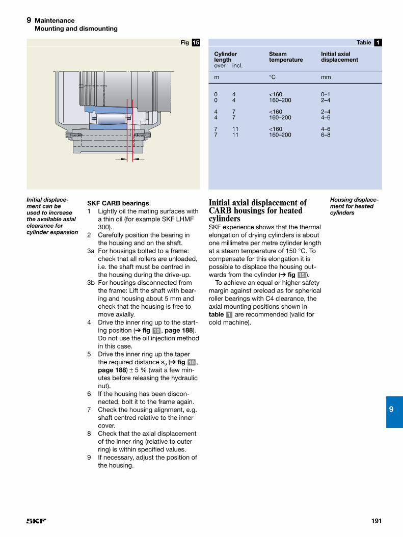
191
9
9 MaintenanceMounting and dismounting
SKF CARB bearings 1 Lightly oil the mating surfaces with
a thin oil (for example SKF LHMF300).
2 Carefully position the bearing inthe housing and on the shaft.
3a For housings bolted to a frame:check that all rollers are unloaded,i.e. the shaft must be centred inthe housing during the drive-up.
3b For housings disconnected fromthe frame: Lift the shaft with bear-ing and housing about 5 mm andcheck that the housing is free tomove axially.
4 Drive the inner ring up to the start-ing position (➔ fig , page 188).Do not use the oil injection methodin this case.
5 Drive the inner ring up the taperthe required distance ss (➔ fig ,page 188) ± 5 % (wait a few min-utes before releasing the hydraulicnut).
6 If the housing has been discon-nected, bolt it to the frame again.
7 Check the housing alignment, e.g.shaft centred relative to the innercover.
8 Check that the axial displacementof the inner ring (relative to outerring) is within specified values.
9 If necessary, adjust the position ofthe housing.
10
10
Initial axial displacement ofCARB housings for heatedcylindersSKF experience shows that the thermalelongation of drying cylinders is aboutone millimetre per metre cylinder lengthat a steam temperature of 150 °C. Tocompensate for this elongation it ispossible to displace the housing out-wards from the cylinder (➔ fig ).
To achieve an equal or higher safetymargin against preload as for sphericalroller bearings with C4 clearance, theaxial mounting positions shown intable are recommended (valid forcold machine).
1
15
15Fig
Initial displace-ment can be used to increasethe available axialclearance forcylinder expansion
Cylinder Steam Initial axiallength temperature displacementover incl.
m °C mm
0 4 <160 0–10 4 160–200 2–4
4 7 <160 2–44 7 160–200 4–6
7 11 <160 4–67 11 160–200 6–8
1Table
Housing displace-ment for heatedcylinders

192
9 MaintenanceMounting and dismounting
As the dismounting force on a CARB bearing must be applied on theouter ring, the use of the SKF pullershown in fig is strongly recom-mended. The use of a puller is possibledue to the design of the CARB bearinghaving more space between rollers,cage and outer ring compared with aspherical roller bearing.
For more information about dis-mounting tools, please contact SKF.Please also contact SKF if you wantmounting and dismounting services to be provided. Your local SKF Servicecompany can offer the resources aswell as the equipment in order to guar-antee proper installation and cost sav-ing by reducing secondary damagescaused by improper handling of thebearings to a minimum.
16
DismountingIn most cases drying cylinder bearingsare mounted in non-split housings anddismounted without disconnection ofthe housing from the frame. The shaftis then to be centred in the housing(i.e. all rollers in the bearing are to beunloaded) during dismounting.
First the bearing inner ring is releasedfrom the tapered shaft by the use ofthe SKF oil injection method. The dis-tance between the inner ring side-faceand nut must be about twice the drive-up distance. If the distance is longerthere is a risk of raceway damage.
When the inner ring is released thebearing is to be dismounted from thehousing.
It is often difficult to dismount abearing from a non-split housing. Thereasons are that it is difficult to applyan axial dismounting force by hand andthat sometimes the outer ring tends tostick in the housing, especially if fret-ting corrosion has occurred.
For spherical roller bearings the easiest way is to lift the shaft slightly,pull out the bearing and housing and,when they are outside the machine,press out the bearing.
For spherical roller bearings mount-ed in the machine frame special toolsor methods may be needed.
16Fig
The SKF puller foreasy dismountingof CARB bearings

193
9
9 MaintenanceCondition monitoring
Condition monitoringThe aim of the condition monitoringsystem is to measure the condition of “wear” components and other func-tions that influence machine reliability.The advantage of condition monitoringusing vibration analysis is that it actsas an early warning system. Thismeans that there is time for correctiveactions and bearing replacement canbe well planned (➔ diagram ).
Here are examples of componentsand systems that are measured:
• bearings• felts• gearboxes• electrical motors
Here are examples of “wear” compon-ents that are manually inspectedinstead of monitored:
• seals• doctor blades• roll covers
Multi-parameter monitoringDeveloped jointly by SKF ConditionMonitoring and the SKF Engineeringand Research Centre in the Nether-lands, Multi-Parameter Monitoring isthe most comprehensive, reliable andaccurate approach to machinery mon-itoring and analysis. Collecting and ana-lysing multiple measurement parame-ters greatly increases the capability to
2
Vibration Penplus
The advantage of condition monitoring
! !
!
2Diagram
prewarning time
damage starts
detection by “listen and feel”
bearing failure
detection by SKF condition monitoring
depending onthe background
noise the prewarning time
can vary
vibration noise
time
detection by traditional low frequency vibration monitoring
accurately and readily identify bearingfaults and other machinery problems.
By measuring a number of ma-chinery parameters – from acceleration,velocity and displacement to processparameters like speed, temperature,current, pressure and flow – users gainessential insights into a machine’scondition. Advanced analysis tech-niques like Acceleration Envelopingenable analysts to take the guessworkout of maintenance by supplying theinformation needed to take actiontoward preventing unscheduled downtime

194
9 MaintenanceCondition monitoring
Portable data collectionPortable data collectors like the Micro-log allow efficient data collection andon-site analysis. The models CMVA60and CMXA50 are unique with their embedded expert guidance to assist analysts in diagnosing machineryproblems on the spot. Data collectedby the Microlog may be up-loaded toMachine Analyst™, Windows DataManagement and Analysis Software,for further analysis and trending (➔ page 193).
VibrationTraditional low frequency vibration mon-itoring continues to be an essential inidentifying problematic machinery con-ditions. Generally, malfunctions thatcause vibration and loss of machineefficiency ultimately result in damage tothe machine or its components. Whilelow frequency vibration analysis can bean effective indicator of bearing dam-age, it may not be the most timely.
Acceleration envelopingFor earlier detection of machine faults,enveloping techniques are very effect-ive. Enveloping enhances repetitivesignals caused by the pulses emanat-ing from a damaged bearing, for ex-ample. In the early stages, these typesof bearing flaws generate signals thatmay go undetected amid generalmachine vibration “noise”. The use ofenvelope detection makes it possibleto pinpoint not only the nature, but thelocation of bearing or gear damage.This is the same technique which SKFhas used in its own factories since the1970s to check bearing quality.
Operator toolsEconomical, easy-to-use, handheldinstruments provide a quick and basicindication of problem areas.
The Vibration Penplus (➔ page 193)is a pocket-sized, go anywhere meas-urement device which measures overallvibration levels according to ISO stand-ards and acceleration enveloping peakvalues according to SKF standards.
The hand-held product range alsofeatures the Marlin™ condition detec-tor, which is a hand-held probe thatcollects and compares operating datato provide advance warning of costlymachine problems. Red, yellow orgreen lights indicate machine statusinstantly for assessment of bearingand lubrication problems.
The handheld instrument range provides operators with the means tobecome key participants in ensuringgreater machine reliability. With thepress of a button, operators detectsignificant changes in machine opera-tion which could require further investi-gation.
Microlog CMVA 60
Microlog CMXA50
Marlin™

195
9
9 MaintenanceCondition monitoring
Continuous monitoringOn-line monitoring for round-the-clockbearing and machinery analysis offerssignificant advantages in a harsh paper-making environment. With the MultilogLocal Monitoring Unit, permanentlyinstalled sensors collect data fromhard-to-reach or problem machine sec-tions, eliminating the need for manualor walk-around data collection, whileMachine Analyst™ On-Line displayscurrent information on machine opera-tion for powerful “real-time” analysis.Such systems offer the greatestdegree of worker safety and data consistency.
SKF Machine Analyst™
SKF Machine Analyst™ is a softwareplatform, using an Oracle relationaldatabase, which provides a compre-hensive reliability solution for manu-facturing plants. It gives the user com-plete control over condition monitoringdata, as well as analysis and reporting,with extensive customization features.Toolbars, data plots, security levels,screen layout and more can all bechanged to suit individual users.
PRISM4
Written from the ground up usingComponent Object Model (COM)architecture, SKF Machine Analyst™
can be easily and effectively integratedwith third party plug-ins, as well assystems such as ComputerizedMaintenance Management Systems,Enterprise Resource Planning and others.
The software also offers a numberof time saving features. It allows auser to automatically schedule keyoperations like reporting or archivingat specific times or after an actionoccurs, such as uploading data. AnAlarm Wizard automatically calculatesa reliable set of alarm criteria, settingappropriate parameters for vibrationlevels tailored to the specific plant.

196
9 MaintenanceStandstill precautions
The most common method with oillubrication is to remove the water byincreasing extractor capacity beforeclosing down, e.g. using a portablevacuum extractor. In some circulatingoil systems it is even possible to let theoil continue to circulate during stand-still, which is of course an advantage.
SKF LHVI 1 is a rust inhibiting agentwhich creates a vapour that coats andprotects surfaces from corrosion. Itcan be added to the oil to improvecorrosion protection in machines thatare stored for some time. Before themachine restarts, the oil should bedrained. It is also suitable for use onexternal components where a tackyfilm is acceptable e.g. castings, pumps,valves and compressors. The agentshould not be used in the oil formachines that are in operation, since it then can clog the filters
SKF LHVI 1
Standstill precautionsDespite the use of water extractors,many oil lubrication systems have smallquantities of free water, especially inthe forming and press section. Greaselubricated bearings also may have freewater in the lubricant.
The highest risk of water ingressprobably occurs during high-pressurecleaning of machine frames, wires andfelts. Free water in the lubricant, espe-cially water mixed with cleaning chem-icals, will rapidly start a corrosion pro-cess on bearing surfaces when themachine is at a standstill. There aresome different ways of avoiding suchcorrosion:
• never direct the high pressure spraynozzle towards the sealing gap
• keep the water outside the bearingby more efficient seals
• with oil lubrication, remove the freewater by using more efficient waterextractors
• replace the contaminated lubricant(grease or oil in a bath) by fresh andclean lubricant
The last alternative is the one mostcommonly used method for greaselubricated bearings. Fresh grease isinjected just before closing down.

197
9
9 MaintenanceHow to store spare bearings
Bearing store
Recommended maximum storage time (from the packing date)1)
Relative air Temperature Storage timehumidity
% °C years
60 20–25 10
75 20–25 5
75 35–40 3
Uncontrolled tropical conditions 1
1) Recommendation is valid for open bearings only. For lubricated (sealed) bearingsrecommended time is 3 years maximum
2Table
When the roll has been taken outfrom the machine our recommendationson actions (➔ page 198) should be followed. However, by experience weknow that this is often not done beforethe regrinding resulting in bearing cor-rosion. Therefore, to be on the safeside, grease lubricated bearings shouldbe regreased during rotation, after thecleaning procedure, just before themachine is stopped. Note that thegrease quantity must be large enoughto press out all contaminated grease.If the cleaning of the rolls happensoutside the machine, it is important tocover the seals so no water can enterthrough the seals. For oil lubricatedbearings the housing should beflushed with oil to which rust inhibitorSKF LHVI 1 has been added as soonas the roll is dismounted from themachine.
How to store spare bearingsUnused bearingsWhen it comes to unused bearingsthese should be stored in the originalSKF packaging in an indoor low-humidity store.
The store should:– be clean– be dry– be free from air flow– have air conditioning if the relative
humidity in the store is >75 %– be free from vibrations– have a constant temperature.
Max temperature fluctuation: 3 °C/48 hours.
Table gives recommemded maxstorage time.
Used bearingsPapermills have a number of sparerolls in their roll store. Some of theserolls like suction, press and calenderrolls are regularly reground and re-placed in the machine, while othersare only stored for security reasons.The latter type of rolls can be storedfor a long time.
Before taking out a roll from themachine it is normally high pressurecleaned. The roll is then stored, oftenfor several weeks, before regrinding.During this period there is a great riskof corrosion if water is present in thehousing.
2

198
9 MaintenanceHow to store spare bearings
For bearings that are going to bestored for a lengthy period we recom-mend the following actions:
• in the case of grease lubricatedbearings, dismount the bearinghousings and remove all old greasefrom the bearings and the housings
• if possible, dismount the bearingsfrom the journals
• wash the bearings with a very thinclean oil
• inspect the bearings to ascertainwhether or not they can be used forfurther service in the machine
• remount the bearings and the housings
• lubricate and protect the bearingsagainst corrosion. This can be donewith the same lubricant that is usedin the machine.
• if possible, place the roll in a storewhere it is supported by the bearingsand subjected to perpetual rotation.
• bearings that are to be stored understatic conditions, either dismountedor on the journals, must be protectedagainst corrosion. Grease lubricatedbearings can be packed with freshgrease. Oil lubricated bearings canbe protected with a rust inhibitore.g. SKF LHVI 1 or rust-inhibiting oil,e.g. SKF LHRP 1. Up to one year’sprotection can be obtained. There-after, preservation needs to berepeated.

199
9
This method cannot be used forCARB bearings because of the verysmall contact angle for these bearings.With preloading there would be a riskof indentations. For CARB we recom-mend transportation with all rollingelements free to move. This is achievedby positioning the housing so that theradial internal clearance is the same inall positions of the bearing.
How to avoid transportdamageThe best and only fully safe way toavoid bearing damage is to transportthe bearing in its original packagingand only unpack the bearing at thefinal destination.
When installed bearings are trans-ported, the rollers should either bepreloaded or completely free to move.When the rollers are preloaded there isusually no risk of sliding and smearing.However, during transportation underbad conditions small movements some-times occur causing false brinelling.
Since the rolling element weight isrelatively small, the contact load in abearing with free rollers is usually notlarge enough to cause smearing evenif the rollers are sliding in the bearing.However, during transportation underbad conditions the rolling elementweight might be enough to causesmearing.
The best way to reduce the risk ofdamage in installed spherical rollerbearings is to axially preload one ofthe roller rows. The axial preloadingshould be around 10 % of the C value.In the bearing the rollers in one of therows will be preloaded and the rollersin the other row completely free tomove.
9 MaintenanceHow to avoid transport damage

200
9 MaintenanceFailure modes
Failure modesMost bearing damage in modernpaper machines consists of minor sur-face damage as a result of inadequatelubrication and/or contamination orimproper handling during mounting or dismounting. However, corrosionduring standstill is perhaps the mostcommon problem today. Other reasonsfor bearing damage are vibration marksand passage of electric current.
One bearing may be subjected toseveral failure modes at the same time,though these modes are in differentstages of development. This is illus-trated by the following examples offailure modes.
Normal fatigueWhen a rolling bearing is rotating, andis loaded to a certain level, it is sub-jected to a phenomenon called fatigue.This occurs when a rolling body cre-ates high, alternating stresses beneaththe raceway surface. The most dan-gerous stresses are the shear stresseswhich change direction during everypassage of a rolling element. If suffi-ciently high, these stresses cause acrack to form below the raceway sur-face (➔ fig ). With the passage oftime, this crack grows until eventuallythe material above the crack breaksaway.
Normally, paper machine bearingsare selected on a basis of life calcula-tion using the well-known ISO equa-tion for basic rating life. By definition,
17
90 % of the bearings will reach thecalculated life before the first sign ofnormal fatigue occurs.
Fig shows an early stage ofspalling in a drying cylinder bearing.Note that the size of the spall at thisearly stage is only a few millimetres.Note too that this bearing has beenrunning with adequate lubrication.
The aim for all bearing applications isthat the bearings should not be dam-aged before normal fatigue develops.Unfortunately, it is rare for papermachine bearings to run until normalfatigue occurs.
Bearings might be damaged due toa number of reasons and fail prema-turely, meaning that the service life ofthe bearing is shorter than the calcu-lated life. Research by SKF shows thatwater also has a major influence onthe bearing service life. The SKF recommendation is that water contentin the lubricant should not exceed 200ppm (0,02 %). According to laboratorytests water content of 0,1–0,5 %halves the bearing service life.
18
P
0,3 – 0,5 mmn
17Fig
Spalling caused by fatigue
18Fig
Spalling caused by normal fatigue

201
9
9 MaintenanceFailure modes
20Fig 19Fig
Back of indentation
Spalling
Spalling caused by indentation
Spalling caused by indentation
Premature failure due to indentationsIf the lubricant contains hard contam-inant particles larger than the oil filmthickness or the bearings are handledin an improper way during mounting ordismounting there is a risk of heavyindentation to the surfaces in therolling contact. Raised material, due toplastic deformation by heavy indenta-tions, causes fatigue. The reason is theload concentration on the raised rimaround the indentation.
When the fatigue reaches a certainlevel it leads to premature spallingstarting at the far end of the indenta-tion (➔ figs and ). The spallingstarts as a crack beneath the surfaceand occurs sooner than normal sub-surface spalling. This is why it is calledpremature. Subsurface spalls and alsospalls starting at an indentation, arenormally at least one millimetre in size.
The SKF Life Method makes it possible to calculate the life reductioncaused by indentations. The mostimportant operating data required forthe calculation are the bearing typeand size, the rotational speed, bearingload, oil viscosity at operating temper-ature and the size, hardness and concentration of the contaminationparticles.
2019
Lubricant cleanliness, and carefulhandling during mounting are of courseimportant factors in the prevention ofheavy indentations. In some paper-mills around half of the failures in thepaper machine are caused by impropermounting,because of lack of know-ledge and improper mounting tools.

202
9 MaintenanceFailure modes
Small sliding inspherical rollerbearings
21Fig
Areas with small sliding
Points with true rolling
Premature failure due to abrasive wearAbrasive wear is a relatively mild formof wear and does not cause any majorproblems until the internal geometry ofthe bearing changes too much. Abras-ive wear occurs between two matingsurfaces sliding in relation to eachother. The sliding motion causes ab-rasive wear of the surfaces in muchthe same way as when a surface issandpapered.
Sliding would not be expected tooccur in rolling bearings, but in actualfact there is always some sliding in therolling contact. In most cases this slid-ing is very small and therefore it is alsocalled micro slip.
Fig shows how micro slip occursin spherical roller bearings, which arethe most common type of bearings inpaper machines. The roller surfacespeed will be highest at the middle ofthe roller where the diameter is greatest.The diameter at the ends of the rolleris smaller which means a lower sur-face speed. This difference in surfacespeeds will lead to the micro slip in therolling contact. While in rolling contactthe distance slipped is short and longscratches will not be produced by con-taminants although small particles willabrasively wear the raceway surfaces.
Fig shows a bearing where ab-rasive wear has led to fatigue spalling.Two ridges remain where true rollinghas taken place. Where micro slip hasoccurred there has been abrasivewear. When loading is concentrated at
22
21
22Fig
Overload andspalling caused by wear
these ridges they become overloadedand fatigued, i.e. premature spallingoccurs. The oil is almost certain to beequally contaminated in these truerolling zones but there is negligibleabrasive wear. The two bands wheretrue rolling has occurred are clearlyvisible in the photo showing a Yankeecylinder bearing (➔ fig ). Note thatthe bearing in the photo is of an olddesign.
The best ways to avoid abrasivewear in paper machine bearings are to increase the oil film thickness, toimprove the cleanliness of the oil, anduse an oil with good AW properties.
22
23Fig
Polishing wearcauses mirror-likesurfaces
Flat surfaces due to polishing and plasticdeformation of the surfaces asperities

203
9
9 MaintenanceFailure modes
encing the start of the polishing wearprocess, e.g. a certain combination oflow speed, heavy load and thin oil film.
The best way to avoid this kind ofabrasive polishing wear is to increasethe oil film thickness and use oils withgood EP or AW properties.
Surface distressThere is a risk of surface distress in all bearings with a thin oil film. Thatrisk is increased if there is sliding inthe rolling contact. As stated earlier,rolling bearings show some sliding(also called micro slip) in the rollingcontacts. Surface distress falls intotwo categories – general and local.
General surface distress is the con-sequence of asperities coming in directcontact under mixed or boundary lub-rication conditions (➔ fig a). Whenthe loading and the frictional forcesrise to a given magnitude, small cracksform in the surface and these crackscan in turn develop into microspalls (➔ figs b and c). Generallythese microspalls are not visible to thenaked eye, because they are only afew microns in size. The surface justlooks dull and grey, but under a micro-scope a number of cracks and spallscan be detected.
Microspalls can also be caused bythe EP additives being too aggressive,especially at elevated temperatures.
2525
25
Polishing wearThe raceway surfaces of new rollerbearings are shiny but not highly reflect-ive. Therefore, mirror-like surfaces in a roller bearing mean that something,sometimes referred to as polishing, hashappened during operation.
The most usual explanation for mir-ror-like raceway surfaces in a rollingbearing is that the bearing has beenpoorly lubricated, which normallymeans a thin oil film. A thin oil filmallows metal-to-metal contact thatleads to wear and plastic deformationof asperities (➔ fig ).
Mirror-like surfaces are an advantageas long as wear and plastic deforma-tion of the surface asperities are mild,i.e. the “treatment” of the surface isconfined to the asperities only.
Sometimes mirror-like surfaces arecombined with heavy wear (➔ fig ).The question is how the surfaces canwear down by up to one millimetreand still be mirror-like? The explana-tion is that the surfaces have not beenable to build up an oil film, despite thesurface roughness improvement pro-duced by the first polishing action.Viscosity of the oil is too low and thereare a lot of very small abrasive con-taminant particles in the oil. The bear-ing has been subjected to continuouspolishing wear.
These microparticles are alwayspresent in a lubricant, but not everybearing with a thin oil film becomespolished. Why is this? It is presumedthat there are additional factors influ-
24
23
24Fig
Polishing wear:Mirror-like surfacecombined withheavy wear
25Fig
a)
b)
c)
Surface distress:Micro spallingcaused by metal-to-metal contact

204
9 MaintenanceFailure modes
rims are the reasons why bearings withheavy indentations should be replacedas part of the preventive maintenanceprogramme.
SmearingSmearing, just like most other lubrica-tion-related damage, occurs betweentwo mating surfaces sliding in relationto each other. The difference is thatsmearing is a severe type of wear thatoccurs at rolling contacts when the oilfilm is broken due to high sliding speedand/or heavy loads.
Therefore, smearing is not commonin the rolling contact under normaloperating conditions. The sliding speedmust be much higher than in the slipmentioned on earlier pages.
One critical position is, for example,where the rollers are accelerated asthey enter the loaded zone in bearingsoperating at high speeds. Another example of critical positions is the surfaces for cage centring.
In the old-fashioned spherical rollerbearing design with a central integralflange on the inner ring (➔ fig )there is a great risk of smearing be-tween the roller end and the flange.SKF nowadays do not manufacturesuch bearings.
Note that the two retaining flanges,that SKF also has on CA bearings (➔ fig , page 14) never are in con-tact with the roller ends and thereforenever cause smearing.
4
28
Figs and show surface dis-tress in an advanced stage, i.e. howmicrospalls have developed to mediumsize spalls of 10 to 100 µm in size.Note that the debris from microspallscan also increase the abrasive wear.
The best way to avoid general sur-face distress is to increase the oil filmthickness and use oils with good EP orAW properties.
The second category of surface dis-tress is called local surface distress.
Raised rims, as around heavy in-dentations, are even more likely tocause surface distress because thelubricating oil film can easily be broken at these local defects.
The risk of local surface distress andthe load concentration on the raised
2726
27Fig
Micro spalls inhigh magnification
26Fig
Dull surface dueto micro spalling
28Fig
Old design, stillused by somemanufacturers

205
9
9 MaintenanceFailure modes
The heat generation in earlier men-tioned sliding contacts may be so greatas to cause the oil film to collapse. Thetwo surfaces melt together at the pointsof metal-to-metal contact (➔ fig ).This welding process causes materialto be transferred from one surface tothe other, which leads to higher frictionas well. This phenomenon is alsocalled galling, scuffing or adhesivewear.
Smearing is the most dangeroustype of surface damage as the sur-faces affected normally become pro-gressively rougher. As the rough sur-faces lead to decreased oil film with a lot of metal-to-metal contact, thebearing is in a vicious circle. In heavilyloaded bearings smearing may lead toserious damage like blocked rollersdue to a broken cage.
In lightly loaded bearings, which arecommon in paper machines, smearingnormally leads to premature spalling,(➔ figs and ).
The best ways to avoid smearing innormally loaded bearings like those inpress rolls is to increase the oil filmthickness, to use lubricants with effi-cient EP additives and to reduce thewater content in the lubricant.
In bearings with radial loads belowthose recommend in our GeneralCatalogue, we recommend the use ofNoWear bearings with coated rollers(L5DA). With such bearings the stand-ard lubricant used for the other rolls inthe calender can be used.
3130
29
29Fig
Welded material
Heavy slidingcauses smearing
30Fig
Figs 30 and 31Smearing normallyleads to prematurespalling
31Fig
There are also some polyglycol oilson the market that can prevent smear-ing. However, consideration needs tobe given to cost and environmentalissues with such oils.
Some polyglycols have a tendencyto dissolve water, which in turn willdecrease the lubricant viscosity andincrease the risk of corrosion andhydrogen embrittlement.

206
9 MaintenanceFailure modes
Deep-seated rust under staticconditions
33Fig 32Fig
Water concentra-tion in a stationarybearing
Roller
Outer ring
Water Water
CorrosionCorrosion is perhaps the most com-mon reason for short service lives inpaper machine bearings.
Bearing applications in papermachines are exposed to the ingressof water, especially in the forming andpress section of the machine. Water,either from the papermaking processitself or from hosing down when themachine is cleaned, is very dangerous.The risk of corrosion is highest in non-rotating bearings, e.g. in the roll store.
If a non-rotating bearing has freewater in the lubricant this water willaccumulate at the bottom of the bear-ing. Concentration of the water will behighest at a certain distance from therolling contact (➔ fig ). The reasonis that the free water in the oil, beingheavier, will sink until it comes to asuitable gap between the roller andthe raceway.
The bearings in the dryer section are subjected to another type of corro-sion. High temperatures and aggres-sive chemicals may cause a type ofcorrosion referred to as etching. Forexample, some EP additives haveproved to be aggressive at high temperatures.
Deep-seated rust usually leads topremature, extended spalling as thematerial is subjected to structuralchange and the area of the load-carrying surface is reduced to such an extent that overloading occurs.
32
Fig shows a bearing which hasdeveloped deep-seated rust understatic conditions.
The best way to avoid corrosion isto keep the lubricant free from waterand to use a lubricant with good rustinhibitor additives.
CracksNormally some kind of initial damageis needed to cause ring cracking.Examples of initial damage are surfacedistress, indentation, smearing, corro-sion, handling marks and mountingdamage.
The best way to avoid ring crackingis to use case hardened rings. There-fore SKF recommends case hardenedinner rings (HA3) for drying and Yankeecylinder bearings.
33

207
9
9 MaintenanceHow to avoid surface damage
How to avoid surfacedamageAs mentioned, bearings in papermachines are subjected to differenttypes of surface damage, mainlycaused by insufficient lubrication. Assuch damage is often a combinationof two or more failure modes it is diffi-cult to propose a single action whichcan prevent the damage. The best lub-rication conditions, i.e. smallest risk ofsurface damage, are obtained when allthe guidelines in this handbook havebeen followed. However, table cangive some guidance on suitable actionswhen different types of surface damagehave occurred.
In extreme cases, like smearing because of zero load in calenders,NoWear™ bearings can be a problem-solver. Please contact SKF for furtherdetails.
There are other special guidelinesfor the avoidance of damage to bear-ing contact surfaces. For example, inorder to avoid premature spalling it isalso necessary to ensure that hardparticles and water are removed from
3
the lubricant. Further information canbe found under the heading “Cleanli-ness control” (➔ pages 98–102).
Sometimes one or two parametersare more important than the others. Vis-cosity ratio κ is one example of suchan important parameter. Therefore SKFhas some special guidelines for oil lub-ricated paper machine applicationswith respect to these parameters.
GuidelinesWith the restriction below the followingequation can be used as a rule ofthumb when selecting κmin:
κmin = n × dm/80 000
whereκmin = minimum value for κn = rotational speed, r/mindm = bearing mean diameter, mm
Restriction:The equation is valid for κ values be-tween 1,0 and 4,0 but in the case ofbearings for heated rolls it is not alwayspossible to achieve κ values above1,0. In such cases it is permitted to
Recommended Type of damageaction Abrasive Polishing Surface Smearing Smearing Corrosion Inner ring
wear wear distress (welding at (welding at etching crackingnormal load) light load)
Increase the oil filmthickness (κ-value) X X X X
Improve AW additives X X X
Improve EP additives X X X
Decrease activity of EP additives(sulphur/phosphorous typeat elevated temperatures) X X
Improve water extraction X X X
Improve particle removal X X
Improve rust inhibitor additives X
NoWear™ X X X X
Case hardened inner ring (HA3) X
3Table
Recommendedactions to avoidsurface damage

208
9 MaintenanceHow to avoid surface damage
extend use of the equation to the κminrange of 0,25 to 1,0 with reasonableaccuracy. SKF experience is that verylittle is gained by increasing the κvalue above 4,0.
The equation for the κmin value isbased on the risks of surface distressand smearing, which in turn are de-pendent on the bearing size and speed.The bearing load also has influence but,in the case of paper machine applica-tions, the load is normally very light.When lubrication is selected by usingthis equation the risks of surface dis-tress at low speeds and of smearingat high speeds are very low. The bestthing would be if κ = 4,0 could beapplied to all the bearings, but this isnot possible with the oils and lubrica-tion systems in common use. There-fore, the κmin equation is also based ona limited range of standard oils for, andon common oil flow rates in, modernpaper machines. Slightly higher κvalues than κmin can be attained formost paper machine bearings, espe-cially in the forming and press section,and will further reduce the aforemen-tioned risks. One exception, where theκmin value cannot be reached, is dry-ing cylinders without journal insulationor with very high steam temperature.Dryer bearings in such machines aretherefore subjected to higher risks ofsurface distress. When optimal lubri-cation is required, each applicationhas to be calculated separately bySKF. Note that the above equation andthe examples included in this hand-book are to be used as general guide-lines only!

MG cylinders ………………………… 54, 62Microlog ………………………………… 194Mineral oils ……………………………… 96Minimum life……………………………… 10Misalignment …………………………… 13Mixed lubrication …………………… 84, 85Multi-nip press ……………………… 39, 41Multi-parameter monitoring ………… 193Multi-row radial ball bearings ………… 16
NNAS standard ……………………… 98-99Newsprint machines ……………………… 9NLGI index ……………………………… 92Non-locating side ……………………… 13NoWear bearings …………………… 26, 73
OOil analysis………………………… 101-102OilCheck monitor ……………………… 102Oil film………………………………… 84-85Oil filters ………………………………… 99Oil flow resistance…………………… 24-25Oil injectors …………………………… 186Oil outlet ………………………………… 21Oil pumps ……………………………… 186Oil sampling …………………………… 102OME (Overall Machine Efficiency) …… 181Operating speeds …………………… 9, 26Oscillating doctors ……………………… 66Outsourcing …………………………… 184
PParametric studies ……………………… 12Particle content ………………………… 98Particle counting ………………………… 99Plain bearings …………………………… 17Plain calender rolls ……… 72-73, 166-175Plain press ……………………………… 39Plain press rolls ………………………… 44Polishing wear …………………… 202-203Predictive maintenance ……………… 182Press rolls ………………… 44-45, 122-125 Press section ………………………… 9, 39Preventive maintenance ……………… 182PRISM4 ………………………………… 195Proactive maintenance ……………… 183Pullers …………………………………… 186Pulp drying machines …………………… 9
RRadial run-out …………………………… 26Reactive maintenance ………………… 182Rebuilding ……………………………… 185Recommended bearing life …………… 11Reel drums …………………… 78, 176-179Reeler ………………………………… 9, 77Reel spools ……………………………… 79Regrinding ……………………………… 26Reliability ………………………… 182-184Relubrication ………………………… 93-94Rewinders ……………………………… 77Rocker housings ……………… 19, 58, 63Roll former ……………………………… 30Rotating misalignment ………………… 47Running accuracy ……………… 16, 26, 47
FFailure modes ………………………… 200Fatigue life……………………… 10-11, 200Felt rolls…… 33, 43, 56, 118-121, 128-131Felt roll housings …………………… 18, 56Felt run …………………………………… 51Filter rating ……………………………… 99Fine paper machines …………………… 9Flaking …………………………………… 10Flushing ………………………………… 100Forming section ……………………… 9, 29Forward drive rolls …………… 32, 106-109Fourdrinier machine …………………… 29Front side ………………………………… 13Full lubrication ……………………… 84-85
GGauging taper deviation …………… 23-24Gear drive………………………………… 54Granite rolls ……………………………… 44 Grease lubrication ……………………… 91Guide rolls ……………… 33, 43, 162-165
HHeated press rolls ……………………… 42Heaters ………………………………… 186Heat treatment…………………………… 16High precision bearings ………………… 26High pressure cleaning ………… 196-197High speed machines…………………… 26HMV nuts ……………………………… 186Hood ……………………………………… 55Housings ………………………………… 18Hydraulic diameter ……………………… 24Hydraulic nuts ………………………… 186Hydrostatic shoes ……………………… 42
IImpulse drying …………………………… 42Indentations …………………………… 201ISO standard …………………… 12, 86, 99
JJournal insulation ……………………… 56Journals ………………………………… 18Jumbo rolls ……………………………… 77
KKinematic viscosity ……………………… 86KPI (Key Performance Indicators) …… 184
LLabyrinth seal …………………………… 20Linear load ……………………………… 39Liner machines …………………………… 9Locating side …………………………… 13Low load ………………………………… 26Lubricant viscosity ……………………… 12Lubrication ……………………………… 83Lubrication systems ………………… 95-96
MMachine calendering …………………… 69Machine efficiency ……………… 181-182Machine glazing ………………………… 69Maintenance …………………………… 181Marlin …………………………………… 194Mean rotational speed ……………… 79-80
209
IndexAAbrasive wear ………………………… 202Acceleration enveloping ……………… 194Additives ………………………………… 88Air drying ………………………………… 54Air humidity …………………………… 197Anti-corrosion additives………………… 88Anti-foam additives……………………… 88Anti-oxidation additives ………………… 88Automatic grease lubrication ………… 91Availability…………………………………184AW (Anti-Wear) additives ……………… 89
BBall bearings …………………………… 16Basic rating life ……………… 10-11, 86-87Blade former …………………………… 30Board machines…………………………… 9Boundary lubrication ……………… 84-85Breaker stack, ………………………54, 65Breast rolls …………………… 32, 106-109
CCalenders……………………………… 9, 69CARB …………………………………… 15Case hardened bearings ……………… 56CC (Crown Control) roll ………………… 40Central roll ……………………………… 41Centrifugal water extractors …………… 98 Ceramic coating ………………………… 26Cleanliness ………………………… 12, 201Cleanliness control ……………………… 98Clearance ………………………………… 16Clearance reduction …………………… 187Coating section …………………………… 9Coefficient of friction ……………… 13, 26Condition monitoring ………………… 193Contamination …………………………… 12Cooling …………………………………… 26Corrosion…………………………… 93, 206Couch roll ………………………………… 9Cracks…………………………………… 206Cylindrical roller bearings ……………… 17
DDandy rolls ……………………………… 29Deep groove ball bearings……………… 17Deflection-compensating rolls ……………… 42, 46-47, 74, 126-127Deflection-controlled press roll………… 41 Designations ………………………… 16-17Detergent additives……………………… 89Dispersant additives …………………… 89Doctor bearings ………………………… 16Doctors ……………………………… 52, 66Double felt run…………………………… 51Downsizing…………………………… 12-15Drive groups ………………………… 52-53Drive side ………………………………… 13Dryer hood ……………………………… 51Drying section …………………… 9, 51, 53Drying cylinder housings ……… 18, 56, 59Drying cylinders … 52, 56, 58-59, 132-144
EEndurance life tests …………………… 10EP (Extreme Pressure) additives ……… 89Explorer…………………………………… 15

Wire rolls ………………… 33-34, 110-113Wire section…………………………… 9, 29
YYankee cylinder housings ……… 19, 62-63Yankee cylinders …… 54, 62-63, 148-161
ZZone-controlled deflection-compensating rolls …… 42, 48
.
SSeals ……………………………………… 20Self-aligning ball bearings ……………… 17 Service life …………………………… 10-11Shake rail ………………………………… 33Shoe press ……………………………… 40Single felt run …………………………… 51Single nip press …………………… 39, 65 SKF Drive-up method …………… 186-190SKF Life Method …………………… 12, 87Slitters …………………………………… 77Smearing …………………………… 26, 204Soft calender …………………… 26, 70-71Spalling ……………………… 10, 200-201Speed rating …………………………… 26Sphered housing………………………… 32Spherical roller bearings …………… 14-15Splash guard …………………………… 20Spool……………………………………… 77Standstill precautions ………………… 196Steam joint ……………………… 56, 59-60Steam temperature……………………… 10Storage of bearings …………………… 197Stretch rolls ………………………… 33, 43Suction press …………………………… 40Suction press rolls …………… 46, 146-147Suction rolls ……………… 35-37, 114-117Supercalenders……………………… 69, 70Surface coating ………………………… 26Surface damage ……………………… 207Surface distress ……………………… 203Synthetic oils …………………………… 96
TTAD (Through air drying) ……………… 55TAPPI …………………………………… 11Thermal expansion ……………………… 59Termo rolls ……………………………… 26TFO (Trouble-Free Operation)………… 184Tissue machines ………………………… 9Tolerances for abutments ……………… 22Tolerances for cylindrical form ………… 22Tolerances for dimension ……………… 22Tolerances for tapered journals …… 22-23Top wire former ………………………… 31Toroidal roller bearings ………………… 15Transport damage……………………… 199Trends …………………………………… 13Triple ring bearings ………………… 47-48Twin wire machine ……………………… 30
UUnplanned stops …………… 55, 181-182Uptime ………………………………… 183
VVacuum rolls …………………………… 52Vacuum water extractors ……………… 98VI (Viscosity Index) improvement additives ………………………………… 89Vibration ………………………………… 26Viscosity class …………………………… 86Viscosity index…………………………… 86
WWashout resistance …………………… 93Water content ……………… 98, 100, 102Water extractors ………………………… 98Wear ……………………………………… 26Wide nip press…………………………… 40Wire changing …………………………… 32
210

R
Rolling bearings in paper machines
Rolling bearings in paper m
achines