R. Akre, P. Emma, P. Krejcik LCLS RFakre@, emma@, [email protected] April 29, 2004 LCLS RF...
20
R. Akre, P. Emma, P. Krejcik LCLS RF akre@ , emma@, [email protected] April 29, 2004 LCLS RF Stability Requirements LCLS Requirements The SLAC Linac SLAC Linac Stability Data SPPS Measurements LCLS RF System
-
date post
19-Dec-2015 -
Category
Documents
-
view
214 -
download
0
Transcript of R. Akre, P. Emma, P. Krejcik LCLS RFakre@, emma@, [email protected] April 29, 2004 LCLS RF...

R. Akre, P. Emma, P. Krejcik
LCLS RF akre@ , emma@, [email protected]
April 29, 2004
LCLS RF Stability Requirements
LCLS Requirements
The SLAC Linac
SLAC Linac Stability Data
SPPS Measurements
LCLS RF System

R. Akre, P. Emma, P. Krejcik
LCLS RF akre@ , emma@, [email protected]
April 29, 2004
LCLS INJECTOR / LINAC
R. Akre, P. Emma, P. Krejcik
LCLS RF akre@ , emma@, [email protected]
April 29, 2004
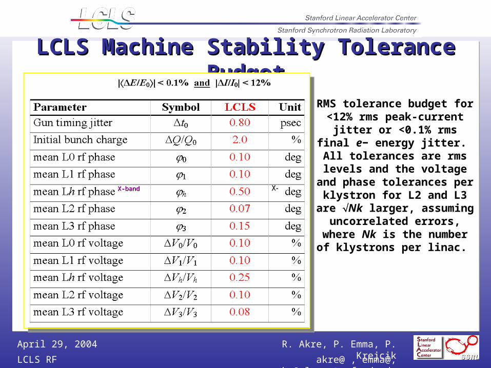
LCLS Machine Stability Tolerance BudgetLCLS Machine Stability Tolerance Budget
X-bandX-band XX--
RMS tolerance budget for <12% rms peak-current jitter or <0.1% rms final e− energy jitter. All tolerances are rms levels and the voltage and
phase tolerances per klystron for L2 and L3 are Nk larger,
assuming uncorrelated errors, where Nk is the number of
klystrons per linac.

R. Akre, P. Emma, P. Krejcik
LCLS RF akre@ , emma@, [email protected]
April 29, 2004
LINAC RF and Timing System
PEP PHASE SHIFT ON MAIN DRIVE LINE MDL RF with TIMING Pulse – Sync to DR
Master Oscillator is located 1.3 miles
from LCLS Injector1.3 Miles to
LCLS Injector

R. Akre, P. Emma, P. Krejcik
LCLS RF akre@ , emma@, [email protected]
April 29, 2004
Linac Phase Reference SystemMain Drive Line - 3 1/8 Rigid Coax Anchored to Concrete Floor Every SectorPhase Reference Line - Each Sector Independent 1/2 “ Heliax

R. Akre, P. Emma, P. Krejcik
LCLS RF akre@ , emma@, [email protected]
April 29, 2004
Linac Phase Reference SystemMain Drive LineMain Drive Line
3 1/8 inch Rigid Coax with 3 1/8 inch Rigid Coax with 30watts30watts
Length = 31 Sectors, 15.5 Length = 31 Sectors, 15.5 furlongs 2miles, 3km : Velocity = furlongs 2miles, 3km : Velocity = 0.98c0.98c
Anchored at each sector next to Anchored at each sector next to coupler and expansion jointcoupler and expansion joint
Purged with dry nitrogenPurged with dry nitrogen
Phase Length Range 100Phase Length Range 100S/YearS/Year
Phase Length Range 40Phase Length Range 40S/DayS/Day
Accuracy Based on SLC Fudge Accuracy Based on SLC Fudge FactorFactor
0.50.5S/Sector Total VariationS/Sector Total Variation
0.2S rms / Sector
Phase Reference LinePhase Reference Line
½ inch Heliax Cable with 1.2 Watts½ inch Heliax Cable with 1.2 Watts
Phase Reference for 8 PADs (Klystrons) Phase Reference for 8 PADs (Klystrons) in the sectorin the sector
Length = 1 Sector, 0.5 furlongs, 332ft, Length = 1 Sector, 0.5 furlongs, 332ft, 400k400kS in ½” HeliaxS in ½” Heliax
Temperature Coefficient 4ppm/Temperature Coefficient 4ppm/CC
Waveguide Water Waveguide Water T = 0.1T = 0.1C rmsC rms
85% of the cable is regulated to 0.185% of the cable is regulated to 0.1C C rmsrms
15% may see variations of 215% may see variations of 2C rmsC rms
Average Temperature Variation = 0.4Average Temperature Variation = 0.4C C rmsrms
= 0.64= 0.64S rmsS rms

R. Akre, P. Emma, P. Krejcik
LCLS RF akre@ , emma@, [email protected]
April 29, 2004
SLAC Linac RF
The PAD measures phase noise between the reference RF and the
high power system. The beam sees 3.5uS of RF from SLED.

R. Akre, P. Emma, P. Krejcik
LCLS RF akre@ , emma@, [email protected]
April 29, 2004
LINAC RF MEETS ALL LCLS SPECIFICATIONSfor 2 Seconds when running well
Amplitude fast time plots show pulse to pulse variation at 30Hz. Standard deviation in percent of average amplitude over 2 seconds are 0.026% for 22-6 and 0.036% for 22-7.
Phase fast time plots show pulse to pulse variation at 30Hz. Standard deviation in degrees of 2856MHz over 2 seconds for the three stations are 0.037 for 22-6 and 0.057 for 22-7.

R. Akre, P. Emma, P. Krejcik
LCLS RF akre@ , emma@, [email protected]
April 29, 2004
LINAC RF is Out of LCLS Specs in 1 Minute
14 minutes data taken using the SCP correlation plot
Note that 22-6 and 22-7 are correlated in phase and amplitude
Amplitude
22-6
0.20%pp
Amplitude
22-7
0.43%pp
Phase
22-6
1.2 Deg pp
Phase
22-7
1.2 Deg pp

R. Akre, P. Emma, P. Krejcik
LCLS RF akre@ , emma@, [email protected]
April 29, 2004
Phase as Seen by Electron is Difficult to Measure
Accelerator Water Temperature Effects on the Phase Through the Accelerator -8.6 S / F
SLAC Linac Accelerator Water Temperatures T< .08Frms
Phase Variations Input to Output of Accelerator > 0.5ºS-Band rms
Single Measurement Can’t Determine the Phase the Beam Sees Passing Through the Structure to LCLS Specifications
Feedback on Input Phase, Output Phase, Temperature, Beam Based Parameters (Energy and Bunch Length) is Required to Meet LCLS Specifications

R. Akre, P. Emma, P. Krejcik
LCLS RF akre@ , emma@, [email protected]
April 29, 2004
Linac Phase Stability Estimate Based on Energy Linac Phase Stability Estimate Based on Energy Jitter in the ChicaneJitter in the Chicane
SLAC LinacSLAC Linac
1 GeV1 GeV 30 GeV30 GeV9 GeV9 GeV
ee Energy (MeV) Energy (MeV)
BPM
221/21/2< 0.1 deg (100 fs)< 0.1 deg (100 fs)
EE/E/E00 0.06% 0.06%

R. Akre, P. Emma, P. Krejcik
LCLS RF akre@ , emma@, [email protected]
April 29, 2004
LCLS Phase Noise Associated Time Referenced to Beam Time
LCLS Laser Need to Measure10uS to 1mS
LCLS Gun 1.1uS SLED / Accelerator 3.5uS Phase Detector (Existing) 30nSDistribution System 200nS
1km @ c-97%c=100nS
Far Hall Trigger 2uS3km @ c-80%c=2uS
TIME
-3.5us SLED Starts to Fill
-1.1uS Gun Starts to Fill
-2uS Far Hall TrigRF Starts Trip
Beam Time 0Reference
R. Akre, P. Emma, P. Krejcik
LCLS RF akre@ , emma@, [email protected]
April 29, 2004
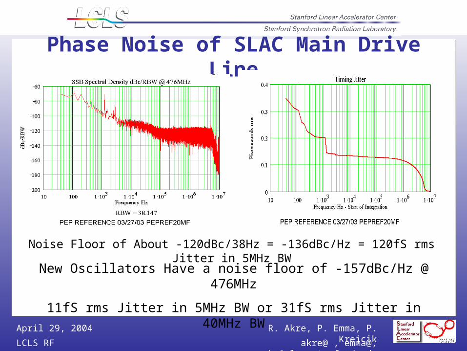
Phase Noise of SLAC Main Drive Line
Noise Floor of About -120dBc/38Hz = -136dBc/Hz = 120fS rms Jitter in 5MHz BW
New Oscillators Have a noise floor of -157dBc/Hz @ 476MHz
11fS rms Jitter in 5MHz BW or 31fS rms Jitter in 40MHz BW

R. Akre, P. Emma, P. Krejcik
LCLS RF akre@ , emma@, [email protected]
April 29, 2004
SPPS Laser Phase Noise Measurements
Phase Noise of Output of Oscillator with Respect to Input
Measurement done at 2856MHz with External Diode

R. Akre, P. Emma, P. Krejcik
LCLS RF akre@ , emma@, [email protected]
April 29, 2004
Jitter determination from Electro Optic sampling
Er
Principal oftemporal-spatial correlation
Line image camera
polarizer
analyzer
EO xtal
seconds, 300 pulses: z = 530 fs ± 56 fs rms t = 300 fs rmsseconds, 300 pulses: z = 530 fs ± 56 fs rms t = 300 fs rms
single pulse
A. Cavalieri
centroidwidth

R. Akre, P. Emma, P. Krejcik
LCLS RF akre@ , emma@, [email protected]
April 29, 2004
LINAC SECTOR 20 – LCLS INJECTOR
RF Stability < 50fS rms : Timing/Trigger Stability 30pS rms

R. Akre, P. Emma, P. Krejcik
LCLS RF akre@ , emma@, [email protected]
April 29, 2004
LCLS RF System – Sector 20 Layout
100ft ½” Heliax = 0.3ºS/ºF

R. Akre, P. Emma, P. Krejcik
LCLS RF akre@ , emma@, [email protected]
April 29, 2004
Beam Trigger for User Facility
Wide Bandwidth – Rising Edge of 8nS ?
Low Phase Noise – 30fS Stability
Design Needs Input

R. Akre, P. Emma, P. Krejcik
LCLS RF akre@ , emma@, [email protected]
April 29, 2004
LCLS RF System
Injector RF – FY06Upgrade of existing system / Lower Noise Timing requirementsInjector/L1 Phase Reference SystemPhase and Amplitude measurement systemSolid State Sub-BoostersBeam Phase Monitor System
X-Band RF system – FY06Linac Phase Reference System – FY07 Linac Feedback Control – FY07Far Hall Trigger – FY08Feedback Development – FY07

R. Akre, P. Emma, P. Krejcik
LCLS RF akre@ , emma@, [email protected]
April 29, 2004
Near Term (6 Month) Tasks
Measure Phase Noise and Response of SPPS Laser
Install New Oscillator, -157dBc/Hz floor, in Accelerator and Measure Phase Noise
Determine Type of RF Phase and Amplitude Measurement System