
R-234 - Investigation of Bichler Brothers Gravel OF BICHLER BROTHERS GRAVEL ... Test results were...
16
MICHIGAN STATE HIGHWAY DEPARTMENT Charles M, Ziegler State Highway Commissioner INVESTIGATION OF BICHLER BROTHERS GRAVEL Myron G, Brown f:\ j ',; tJ Highway Research Project 54 A-16 First Progress Report Research Laboratory Testing and Research Division Report No, 234 July 12, 1955
Transcript of R-234 - Investigation of Bichler Brothers Gravel OF BICHLER BROTHERS GRAVEL ... Test results were...

MICHIGAN STATE HIGHWAY DEPARTMENT
Charles M, Ziegler State Highway Commissioner
INVESTIGATION OF BICHLER BROTHERS GRAVEL
Myron G, Brown
f:\ ~ f'\~T
j ',; tJ ~
Highway Research Project 54 A-16 First Progress Report
Research Laboratory Testing and Research Division
Report No, 234 July 12, 1955

INVESTIGATION OF BICHLER BROTHERS GRAVEL
The purpose of this progress report is to summarize the work done thus
far by the Research Laboratory in regard to an investigation of Bichler coarse
aggregate and, in particular, its possible weakening effect on pavement and
bridge projects utilizing this source, The results of a field survey of con
struction projects using this material are contained in this report,
This investigation was initiated by a letter !rom W, W, McLaughlin dated
March 31, 1954 concerning below specification flexural strengths of Bichler
concrete field test beams on Project SSB2 of 49-4-3,01, Similar low results
on other bridge and pavement projects, notably 21-8,03, 21-6,013 and 21-32,03
were reported in a letter from E. W. Krause to the Research Laboratory, dated
December 16, 1953.
The project files at Ann Arbor were examined and a summary of the avail
able field beam strength results is given in Table 1, The majority of these
tests meet Department specifications but a few are unusually low, Erratic
molding and testing procedure probably was to blame for some of these low
strengths, together with low temperature curing, This was found to be espem
ially true on Projects Bl and B2 of 21-9-12,
Samples of 2NS sand and 6A gravel were received August 13~, 1953 and
also on December 18, 1953. Numerous tests were performed on this material
and also on air-entrained concrete beams molded from it, Test results were
reported by letter dated March 29, 1954. The freeze and thaw beams have now
gone through 300 cycles of slow freezing and thawing in water with the results
shown in Table 2,

TABLE 1
CONSTRUCTION PROJECTS UTILIZING BICHLER GRAVEL IN DELTA COUNTY
Field Beam Test Data
Project Number
Flexural Strengths, psi _____ Ave_. of a:l:l te __ s_t_s __ Pour Date Remarks
7 ;E>ays 2 8 Days --------------- ··--·---- ---- -----------
21-B-C2
21-16-C4
21-6-C10 21-6-2 21-15 3
21-6-0lJ 21-8-CJ }
21-32-03
X 1 of 21-6-1, c1 B1 of 21-8-2l,C1 B2 of 21-8-2l,c3 Bl of 21-9-12 B2 of 21-9-12 B1 of 21-12-23
B1 of 21-13-2
B1 of 21-14-2,02
550
{741 651
f658 l486
545 540 662
509
687 627 534 443 440
{536 588
{554 624 655
MSHD Speeifications
Pavements
816 Oct.-Nov. 1936 Inland 4A & lOA 783 II II II II II & Bi-
chler lOA 763 October, 1948 Bichler C,A, 694 11 11 Ambeau 0 ,A,
754 May-June, 1931 718 June-Oct. 1929 812 August, 1936 Capped with bit,
concrete
541 (l4 ) 1952) 1953 ~ 1953)
~lidtming Projects
Structures
852 Aug,-Oct, 1936 682 July-Oct, 1948 540(10)615( 21) Feb,-Mar, 1932 444 Sept,-Oct.1935 746 Sept.-Oct.1935 720 Sept,-Oct,1941 792 June - 1942 749 June-Sept,1941 756 June-Sept,l941 790 Sept,-Oct,1935
Grade B Grade A Grade B Grade A
Projects not in Delta County -
SSB1 of 2-5-6, 02 SSB2 of 49-4-3,C1
573 469
629 467
1953 1952
Note: All strengths measured at 7 and 28 days field curing exce:9t where indicated ( ) •
- 2-

TABLE 2
DURABILITY OF LABORATORY MOLDED SPECIMNES
Number of Cycles
100 200 260 280 )00
Percent of Original Dynamic Modulus
89 89 71 65 54
Weight Change
%
-0,84 -1.46 -2.50 -2.69 -3.05
Length Change
%
,011 ,02) ,050 ,061 ,062
These beams held up quite well for over 260 cycles of freeze and thaw
before dropping to 70 percent of original dynamic modulus, When compared
to the performance of other gravel sources as graphed in Research Report 195,
dated September 3, 1953, the Bichler gravel beams would be among the best in
durability insofar as resistance to slow freezing and thawing in water is con-
cerned. Two of the three beams are shown in Figure 1 after )00 cycles, One
of the three beams failed at about 260, At the conclusion of this test the
beams had lost three percent of their original weight from scaling and small
pop-outs,
The Bioher gravel pit, (21-12), was visited on July 15, 1954, and the
gravel deposit was studied, The present area of better material was 'bsing
depleted and it was learned that in the spring of 1955 the plant will be lo
cated 1/4-mile to the east where gravel from that area will be used for pro-
duction, In the southwest corner of the present locality, there appeared to
be a darker coloration to the gravel 'bank due, presumably, to leaching and
oxidation by swamp or marsh water in this arsa. Some of the a'bsorbent stone
in this spot could be broken up in the hands, This location is shown in Fig-
ure 2, The 1954 production was coming from gravel to the east of this bad
area and along the south portion of the pit, Figure ),
- 3-

The upper portion of this gravel deposit is a mixture of fine sand and
gravel laid down in an old river delta or alluvial fan on the shore of post
glacial Lake Algonquin. The lower portion contains coarser sand and gravel.
A good share of this stone was originally part of the underlying upper Cam
brian and lower O~dovician sandstones and limestones which generally would be
absorptive and somewhat soft in nature, This softness is apparent in the Los
Angeles abrasion loss of :33.5 percent on gravel samples received at this lab
oratory in August and December of 1953, This material was examined and sep
arated petrographically with a breakdown of rock types shown in Table 3. As
a comparison, the average results of a similar petrographic sorting on six
typical natural gravels from the Lower Peninsula are also included in the
table,
The limestone and dolomite in the Bichler gravel was very heterogeneous
as compared to that found in other natural gravels. Almost all of it con
tained non-calcareous granular particles ranging in size from clay to sand.
Usually, in other natural gravels, the limestone and dolomite are more uni
form in texture and harder, this being the reason for placing them among the
11 hard 11 rock types in Table 3, The ratio of "hard" to "soft" stone in the Bi
chler gravel can be seen to be about 1:1 where, in the average of six other
gravels, the ratio runs about 9:1 or 8:1 assuming that some of the limestone
would be considered partially aoft in nature,
Field Survey of Existing Pavements
A field survey has been made in Delta County of eleven paving projects
which contain Bichler aggregates, See Table 4, The older pavements contain
ed quite a bit of transverse and longitudinal cracks as shown in Figures 4
and 5. The first four projects having 100-foot elabs and all expansion joints
-4-

TABLE J
PETROGRAPHIC SEPARATION OF BICHL;JR GRAVEL No, 4 to l-inch Material
Hook Type
---·--More durable. hard stone
granite
diorite
felsite
rhyolite
basalt
quartzite
limestone and dolomite
chert
Total hard stone
Softer rock types
sandstone and conglomerate
argillaceous limestone and dolomite
yellow sandy limestone
calcareous - purple sandstone
calcareous sandstone
shale
iron bearing clay
Total soft stone
Pergent of Sample Bichler* Aver, of Six
Natural Gravels
16.7
5.6
1.9
4.1
17.4
4.3
4,8
1,2
7.0
6.6
6.7
6,1
7.0
51.7
~
92.0
3.3
4.6
0.8
-------------------* Note: Los Angeles abrasion loss ~1as 33.5 percent on this material,
-5 -

Year Project Built
Non Air-entrained Conc!"c te
21-6,C2
21-6,CJ
21-6,C10
21-16,C2
21-2B,C2
21-15,CJ
21-)2,C2
1928
1929
1931
19)2
1935
19)6
1936
Air-entrained Concrete
Ll-16,C4 . 1940
21-6,011 1951
TABLE 4
PAVEJ{;.'Jf£ PROJECTS UTILIZING BICHLER AGGREGATES
Joint Spacing
100• expn.
100 1 expn.
lOO' EX'!'n.
100 1 expn.
60 1 €.X~m. JC) 1 ciunmy
Scaling
Many s;Jots _of med. to 1-.€ avy scale
Pop-Outs
Occasional
Mode,·ate - mostly Fev: alonr, join~s and cracks
1-!ainly along cracks and joints
Mostly at joints and cracks
Some alone joints and. cracks
Numerous -out small sized
Many small ones
Very few
Covered ui th bituminous concrete cap.
)0' slabs 60 1 ex·7n.
100 1
100 1
Slir,h'-;, :_.t.t joints
Hone
lTone
VerJ few
Vc-:;.' few small ones
None
Condition Observations Transverse
Crac..ldng
l.Jany
lTunt:::-ous
llumc _::- ous -2 to 3 per slab
About 2 per slab
q,ui t.e a few towaro east end of Project
None
Hone
NonE
Loagi tudina.l Cracking
Occasional
Occasional -connecting transverse cracks
Occasional
Vei"J few
None
None
None
None
21-c,CJ 19)2.
2l-6,Cl3 1953
2.1-J:' ,03 1953
} """'~ jo>•, on '" ,.ro '"~"'~
Remarks
SlE~bS br•,ken UTJ into 8 or 10 1
~i~ces. Scaling also along cracks.
Some joints and cracks faulted.
Badly scaled and- cracked limLstone section.
Changed to Ambeau aggregate toHard end of Project.
Good condition thraughout.

contained most of the transverse cracking, averaging about two to three per
slab, The newer air-entrained concrete pavements with the same slab length
exhibited very little or none of this cracking, However, some of the old
projects contained patched sections of limestone concrete which were cracked
and scaled as badly or worse than the original pavement (see Figure 6). Poor
subgrade conditions undoubtedly contributed to the very badly cracked areas
in the older pavements, Although the older pavements of long slab length con~
tained a good deal of transverse cracking, the concrete itself appeared to be
quite sound, Most of the scaling present was found to occur along the cracks
and around some of the transverse and longitudinal joints, An example of an
older pavement in good condition is shown in Figure 7, Project 21-32,02, about
18 years old, The postwar pavement projects appear to be in good condition
throughout.
Field Survey of Bridge Projects
In general, the bridge projects, totaling 17 surveyed and listed in Table
5, were in good shape except for eccasional deterioration exemplified by Fig
ures 8, 9 and 10, This sort of breakdown consisted of sporadic areas of yel
lowish stained cracks and, in some cases, &palling along these cracks, About
seven of the seventeen structures contained this type of defect, This con
dition was probably caused by freeze and thaw action on numerous absorptive
sandstone and limestone particles in the coarse aggregate and consequent lea
ching and oxidation to produce the yellow stain, Figure 11 illustrates one of
the ten structures of seventeen surveyed, >Thich was found to be in sound con
dition and containing no unusual defects of the concrete in particular,
Project B4 of 21-11-12 exhibited extensive damage due to a feature of de
sign rather than through any fault of the concrete, Figure 12 illustrates the
- 6-

No. of Snans &
Project Y•= Length
B! of 21-13-11 1929 7 aC 50 1
x2 of 21-13-11 .1930 48 1
B3 of 21-11-2
::s2 of 21-E-21
B1 of 21-14-2
xl of 21-11-12
B1
of 21-11-l)
B1
of 21-12-2
::s2
of 21-12-2
:s4 of 21-11-2
B2 of 21-9-12
Bi of 21-9-12
x1 of 21-6-1
131 o1' 214-2
B1 of 21-13-2
B1
of 21-12-23
:s1
of 21-0-21
1931 2 at 40 1
1932 3 at 60 1
1935
1935
1936
1936
1936
1936
1936
1936
1936
35'
3 at 36 1
60'
104'
35'
5 at 60 1
6o•
50'
1 a.t 01 1
at 9'
1940 2 at 24 1
1941 3 at 6o•
1942 3 at J5'
1948 70'
Type
1 beM
X.T.G.
r.:s.
I.B.
I beam
I.B.
I beam
S"teel T 1-uss
I beam
I.B.
I.B.
I •. B.
T.P,G.
c.s.
I beam
C,T,3,
D,P,G.
T.AlUJ!: 5
:BRIDGE PROJ"&CTS UTILIZING BICHLm AGGJ.IDATES .
Road1~ay I Sidewalk or
Whu1guard
Black to:p Trans. cracks in s.w.
RR tracks None
Black to:p S,\•1. good
Light scale W,G, good along ~dge
Black top ·,>f ,G, light seale on edges··
Black top W .G. some slllall cracks
Black top W,G.- O.K. some trans, cracks in botton of deck
Deck & sides all st~el C•Jnst::-ucti·:ln
Black top ";I,G,-lt. scale
Bb.ck' top W.G.-lt, scale sm. po~1-outs
:Black to:p 1.~ ,G,-fe>·• ?oPouh
Black top t·I.G. O.X.
RR bed·on O,K, Steel I ,..,.,, Lt. scale. ·a ,G. -
lightly scaled
N~~<rous W,G, O,K, sm. :lOP
Juts
Good con- I~ ,G. good dition
O.K. 'II,G. O.I,
I Pilasters
o.x.
o.K.
O.K. some fine hair cra.c'<:s
O.K.
c
Lt. cracking and disintee;ra.tion
O.K.
I
Some disint. cracks in tops
Fine ;?ellowed er,
eracl.::ed up thru. deck
Fine cr. in tou surface
o.r..
Some corner s:?a].Ung
O.K.
O.K.
Abutments I Wingaa.11s- I__Piera
Light seale a.t waterline
SomE b::-eakdown of concrete an top ede;€-, and cracks in face
Few fine ha.ir cr.
O.K.
Top of so, ·:;ier bro!<-en up.
None
Some fine hair 0, K. O.K. cracks, yello·.<ed
o.E.
Lt. & med. scale on tops
About 4 vert, cracks dow"ll abut, face
Some light cracks
O.K.
Lg. crack aJ. eng base of back-_,·aJ.l
O.K.
Light scale on top
o.x.
•=· Some ~"air line cracking
None
-Light scale on tops- None
Liebt scale on to:? None
Few vert, cracks
o.x:.
O.K.
2 long er, down face
Lt. seale & hair cracks on top surfaces
o.x.
O.K.
Ned, scale on tops, Cracking do'·'n side
Both ends of uier tops cracked ;:. disinte,o:ra.ted
Fill washed out None behind ends. C::-ackin~ at base
Yellow s ta.inEd None cracks
S ·~'"IE crae.'dng On top
o.x.
Seve::-al cr, dO'>-In f'lCes
O.K.
s.)JnE' fine yellow cr. in surface of :pier columns
o.x.
O.K.
O.K.
Rumlilrous :·ellow-O,K, stained cracks
J.!any fine yellow None cracks

design of the load-bearing portion of all four piers. The use of 100-lb
A.R.A. rail for the bearing points in pier tops has been discontinued for some
time, This type of construction has produced large cracks over the entire
length on both sides of all four piers along the top corners. Top views of
the pier ends are shown in Figures 13 and 14. A side view is shown in Fig
ure 15. These cracks carry right up throUgh the deck edge and many of the
pilasters, This damage should be repaired before more advanced deterioration
takes place from freezing and tha~1ing within the cracks now present, such as
is shown in Figure 16, or additional cracking of the piers occurs.
Sunune.ry
In general, the projects, both pavements and bridges, do not show exten
sive cracking which could be attributed to flsXUrally weak concrete resulting
from an inherent weakness of Eichler coarse aggregate, The ~uality of the
gravel does seem to run bad occasionally as iS shown by periodic areas of yel
low-stained cracks and pop-outs in the concrete surfaces of certain structures
and in some of the pavements, The presence of higher concentrations of wea
thered siliceous limestone and sandstone in gravel produced in. the past may
have resulted in some of the low flexure testa of field beams besides showing
up in the form of the yellow cracked areas previously mentioned. This may have
been the oase in Project E2 of 49-4-3,01 where the 6A stone had an unusually
high absorption of 1.96 percent,
The stone from the new location will probably contain a high percentage
of sandstone and siliceous limestone but whether this is badly leached, non
durable, absorbent material is something that will have to be determined from
an adequate number of test samples, It is suspected that this gravel will al
ways tend to give fairly high abrasion losses but not necessarily in excess of
the allowed 36 peroent,
- 7 -

Apparently this material is satisfactory for 6A aggregate when properly
inspected to exclude areas of lower grade material occurring in the pit. The
relatively high deleterious particle content makes it unsuitable for 6B in
its present condition,
-8-
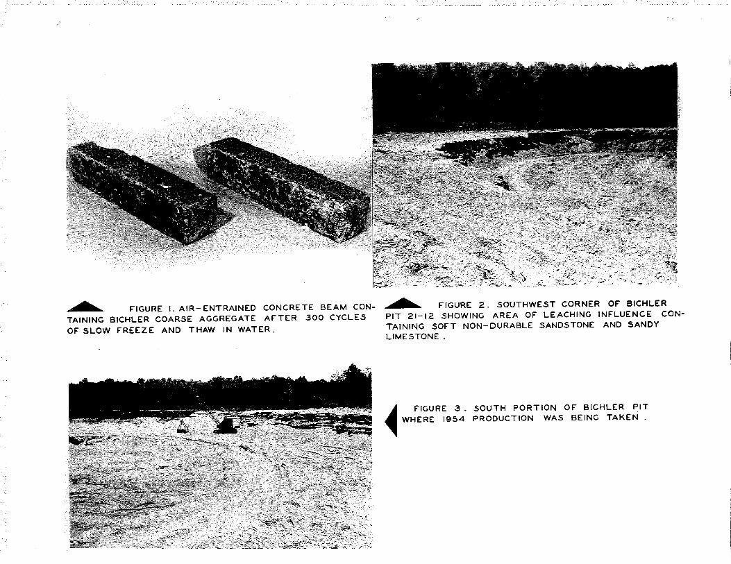
...-.._ F'IGURE I. AIR- ENTRAINED CONCRETE BEAM CON
TAINING BICHLER COARSE AGGREGATE AFTER 300 CYCLES OF' SLOW F'REEZE AND THAW IN WATER.
...-.._ F'IGURE 2. SOUTHWEST CORNER OF' BICHLER
PIT 21-12 SHOWING AREA OF' LEACHING INFLUENCE CONTAINING SOFT NON-DURABLE SANDSTONE AND SANDY LIMESTONE.
~ F'IGURE 3. SOUTH PORTION OF BICHLER PIT ~ WHERE 1954 PRODUCTION WAS BEING TAKEN .

' . -~
I I
- ----------------------------------
f'IGURE 5. SECTION OF" 21-6-CIO CONTAINING MANY TRANSVERSE CRACKS. 23 YEARS OLD.
FIGURE 7. EXAMPLE OF" PRE- WAR PAVEMENT IN GOOD CONDITION WITH NO CRACKING AND VERY LITTLE SCALING. CONCRETE ABOUT 18 YEARS OLD.
~FIGURE 4. BADLY CRACKED AREA IN PROJECT 21-0-C3 NORTH OF" ESCANABA ON US- 2. PAVEMENT 25 YEARS OLD .
f'IGURE 6. PATCHED AREA WITHIN PROJECT 21-28-C 2 CONTAINING LIMESTONE AGGREGATE~ CRACKED MUCH WORSE THAN OLDER BICHLER PAVEMENT MORE RECENT THAN 19 YEAR OLD PROJECT.

FIGURES SAND 9. EXAMPLES OF YELLOW STAINED CRACKS IN BRIDGE SURFACES DUE TO LIMONITIC SANDSTONE IN IN COARSE AGGREGATE. B2 OF 21-9-12 AND B I OF 21-14-21 BRIDGE 18 AND 19 YEARS OLD RESPECTIVELY.
~FIGURE 10. YELLOWED CRACKS AND SPALLING FROM SANDSTONE PARTICLES IN WING WALL SURFACE. B I OF 21- 8-21. ONLY 6 YEARS OLD. .
~FIGURE II. TYPICAL STRUCTURE CONDITION. Bl OF 21-12-23 12 YEARS OLD.
IN GOOD ABOUT

8 SPACES OF 4'-5" ACROSS WIDTH OF DECK
- --- ----- !
36" BY 12" "I" BEAMS I 50 LB.
PIERS I a 4 HAD STEEL STOPS PIERS 2 a 3 WERE FREE TO SLIDE
I" BARS2DIA. I
100.4 LB. A.S.A RAIL TYPICAL CRACK PATTERN SERIES A
I I
60 FEET LONG.
18"
"I" BEAM
CAP OVER END OF RAILS
FIGURE 12. CROSS SECTION OF ALL FOUR PIERS SHOWING
LOCATION OF 100 LB. RAIL IN PIER TOP FOR
BEARING LOAD OF BRIDGE DECK.

FIGURE 14. SOUTH END OF FIRST PIER ON EAST END OF' BRIDGE SHOWING CRACKED PIER AND CRACKS UP THROUGH DECK AND PILASTER.
FIGURE 16. MORE ADVANCED DETERIORATION IN SOUTH END OF FIRST PIER FROM WEST END OF BRIDGE DUE TO FREEZE AND THAW ACTION,
~ FIGURE 13. TOP VIEW, NORTH END OF 2 NO. PIER FROM WE5T END OF BRIDGE SHOWING CRACKING
DOWN THROUGH CORNERS. 84 OF 21-11-2. BRIDGE 16 YEARS OLD.
FIGURE 15. TYPICAL CRACK FOR ENTIRE LENGTH OF' PIER ABOUT ONE FOOT DOWN FROM THE TOP EDGE . THIS OCCURRED ON BOTH SIDES OF' ALL FOUR PIERS.


