QVF Components Catalogue
252
-
Upload
chemlab-international -
Category
Documents
-
view
727 -
download
55
description
QVF Components Catalogue 2002
Transcript of QVF Components Catalogue

QVF 2002
COMPONENTS CATALOGUE
QVF GROUP
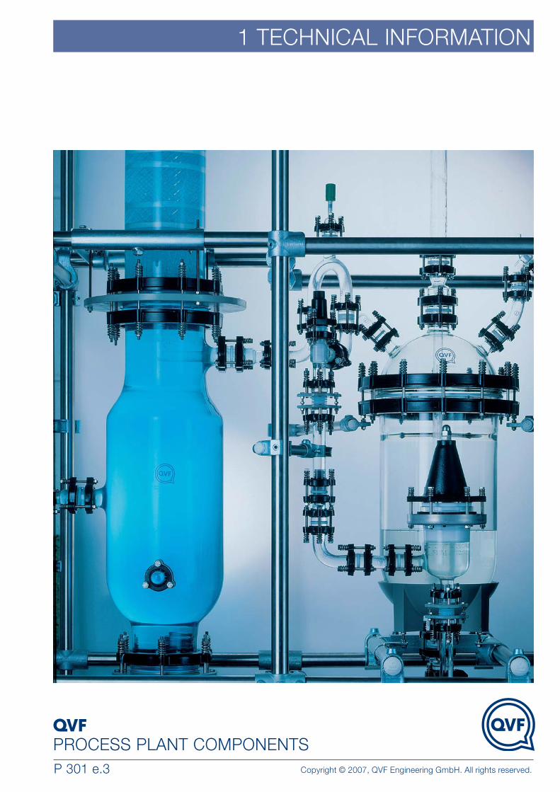
1 TECHNICAL INFORMATION
PROCESS PLANT COMPONENTSP 301 e.3 Copyright © 2007, QVF Engineering GmbH. All rights reserved.

1.2
TECHNICAL INFORMATION
Process plant in borosilicate glass 3.3 QVF process plant and pipeline components manufactured from borosilicate glass 3.3are widely used as the basis for the construction of complete process systemsthroughout the chemical and pharmaceutical industries, as well as many related areas such as food and drink production, dye works and the electroplating industry.One reason for this widespread use is the special properties of borosilicate glass 3.3(see below), complemented by the use of other highly corrosion resistant materialssuch as PTFE and ceramics. Secondly, borosilicate glass is an approved and provenmaterial in the construction of pressure equipment.
Another point which should be mentioned in this context is the great reliability of thepositive and high performance connection of all components. This is achieved by theuse of flat buttress ends, properly designed and optimised throughout the range ofnominal sizes to comply with the special requirements of the material, and a reliableflange system.
The full range of standard components and associated equipment available is described in the following sections of this catalogue.
Chemical composition of borosilicate glass 3.3The special properties – especially its high chemical resistance, its resistance to temperature and its low coefficient of linear expansion – of the borosilicate glass 3.3exclusively used by QVF for the construction of glass plant and pipeline are achievedby strict adherence to its chemical composition, which is as follows:
Properties of borosilicate glass 3.3The very wide use of this material throughout the world in the chemical and pharmaceutical industries as well as many other allied areas, is mainly due to its chemical and thermal properties (see also ISO 3585) together with a great number of other benefits that distinguish borosilicate glass 3.3 from other materials ofconstruction. These include special properties such as
• smooth, non-porous surface
• no catalytic effect
• no adverse physiological properties
• neutral smell and taste
• non-flammability
• transparency
Table 1Component % by weightSiO2 80.6B2O3 12.5Na2O 4.2Al2O3 2.2Trace elements 0.5

1.3
TECHNICAL INFORMATION
Chemical resistanceBorosilicate glass 3.3 is resistant to chemical attack by almost all products, whichmakes its resistance much more comprehensive than that of other well-knownmaterials. It is highly resistant to water, saline solutions, organic substances, halogenssuch as chlorine and bromine and also many acids. There are only a few chemicalswhich can cause noticeable corrosion of the glass surface namely hydrofluoric acid,concentrated phosphoric acid and strong caustic solutions at elevated temperatures.However, at ambient temperatures caustic solutions up to 30% concentration can behandled by borosilicate glass without difficulty.
Borosilicate glass 3.3 can be classified in accordance with the relevant test methods asfollows (see also ISO 3585 and EN 1595):
Further information about acid and alkali attack can be obtained from the followingfigures.
The corrosion curves in fig.1 show a maximum for different acids in the concentrationrange between 4 and 7 N (HCl for example at the azeotrope with 20.2 wt %). Abovethat the reaction speed decreases markedly so that the eroded layer amounts to onlya few thousandths of millimetre after some years. There is, therefore, justification forreferring to borosilicate glass 3.3 as an acid-resistant material.
Table 2Hydrolytic resistance at 98 ºC Hydrolytic resistance grain class ISO 719-HGB 1Hydrolytic resistance at 121 ºC Hydrolytic resistance grain class ISO 720-HGA 1Acid resistance Deposit of Na2O < 100 mg/dm2 to ISO 1776Alkali resistance Alkali resistance class ISO 695-A2
Fig.1 Acid attack on borosilicate glass 3.3 as a function of concentration

1.4
TECHNICAL INFORMATION
It can be seen from the corrosion curves in fig. 2 that the attack on the glass surfaceinitially increases as the concentration of the caustic solution increases but afterexceeding a maximum it assumes a virtually constant value. Rising temperaturesincrease the corrosion, while at low temperatures the reaction speed is so low thatreduction of the wall thickness is hardly detectable over a number of years.
Physical propertiesBorosilicate glass 3.3 differs from other materials of construction used for processplant not only because of its virtually universal resistance to corrosion (see above) butalso because of its very low thermal expansion coefficient. There is, therefore, no needfor expensive measures to compensate for thermal expansion resulting from changesin temperature. This becomes of particular significance in the layout of long runs ofglass pipeline.
The most important physical properties for the construction of plant are listed below(see also ISO 3585 and EN 1595).
Fig. 2 Alkali attack on borosilicate glass 3.3 as a function of temperature
Table 3Mean linear thermal expansion coefficient α20/300 = (3.3 ± 0.1) x 10-6 K-1
Mean thermal conductivity between 20 and 200°C λ20/200 = 1.2 W m-1 K-1
Mean specific heat capacity between 20 and 100°C Cp 20/100 = 0.8 kJ kg-1 K-1
Mean specific heat capacity between 20 and 200°C Cp 20/200 = 0.9 kJ kg-1 K-1
Density at 20°C ρ = 2.23 kg dm-3

1.5
TECHNICAL INFORMATION
Table 4Strength parameters Tensile and bending strength K/S = 7 N mm-2
Compressive strength K/S = 100 N mm-2
Modulus of elasticity E = 64 kN mm-2
Poisson‘s ratio (transverse contraction figure) ν = 0.2
Optical propertiesBorosilicate glass 3.3 shows no appreciable light absorption in the visible area of thespectrum, and consequently it is clear and colourless.
With borosilicate glass 3.3, the transmission of UV light, which is of great importancefor photo-chemical reactions, is somewhat greater in the middle spectrum than withnormal window glass. The chlorine molecule absorbs in the 280 to 400 nm range, andthus from the levels of transmission shown in fig. 3, it can be seen that plant madefrom this material is, therefore, ideal for chlorination and sulphochlorination processes.
If photosensitive substances are being processed, it is recommended that browncoated borosilicate glass 3.3 be used. This special coating reduces the UV lighttransmission to a minimum, since the absorption limit, as can also be seen from thefigure below, is changed to approximately 500 nm.
Sectrans coated glass components, which have an absorption limit of approximately380 nm, are also ideal for these applications.
Fig. 3 Transmission curves for borosilicate glass 3.3
Mechanical propertiesThe permissible tensile strength of borosilicate glass 3.3 (see table 4) includes a safety factor which takes into account practical experience on the behaviour of glassand, in particular, the fact that it is a non-ductile material. Unlike other materials ofconstruction used for similar purposes, it is not able to equalise stresses occurring atlocal irregularities or flaws, as happens in the case of ductile materials such as metals.The safety factor also takes into account additional processing which componentsmay have undergone (ground sealing surfaces), handling of the glass (minute surfacedamage) and permissible pressures and temperatures to which it may be subjected inuse.
The design figures indicated in the table below and specified in EN 1595 thereforeapply to the permissible tensile, bending and compressive stress to which glasscomponents may be subjected taking into account the likely surface condition of theglass in service.

1.6
TECHNICAL INFORMATION
Permissible operating conditionsThe permissible values for operating temperature and pressure must always be seen incombination. The reason for this is the thermal stresses that result from temperaturedifferences between the inner and outer surfaces of the glass component. Thesestresses are superimposed on the stresses resulting from the working pressure. Higherthermal stresses therefore result in a reduction of the permissible working pressure.Thermal insulation reduces the thermal stresses and can, therefore, become arequirement of an installation.
Permissible operating temperatureBorosilicate glass only deforms at temperatures which approach its transformationtemperature (approximately 525 ºC) and up to this point it retains its mechanicalstrength. The permissible operating temperature is, however, considerably lower –normally around 200 °C – for glass components, provided that there is no suddentemperature shock and that the components are not specially marked (see page 1.8).In exceptional cases, which call for special precautions, temperatures up to 300°C arealso possible.
At sub-zero temperatures tensile strength tends to increase. Borosilicate glass 3.3 can,therefore, be used safely at temperatures as low as -80 ºC.
These temperature limits should be regarded only as a guideline and must always bemodified in accordance with the actual operating conditions of a given application. Theindividual operating conditions of some components in this catalogue must also beconsidered. Where such operating limits apply, they are detailed in the individualcatalogue sections and component descriptions
Thermal shockRapid changes in temperature across the walls of glass components should be avoidedduring operation both indoors and outside. They result in increased thermal stress inthe glass which, as described above, has an adverse effect on the permissibleoperating pressure of the plant components. Although it is not possible to give a definitefigure applicable to all the operating conditions likely to be encountered in practice, amaximum permissible thermal shock of 120 K can be taken as a general guide.
Permissible operating pressureGlass components in all nominal sizes that are basically cylindrical, domed andspherical can be used with full vacuum (-1 bar g), provided they are not speciallymarked otherwise.
Likewise the maximum permissible operating pressures (ps) shown in tables 5 to 8apply to these glass components as a function of their principal nominal size DN ordiameter D (in the case of spherical vessels) and the internal (product side) and external(ambient) temperature difference (DQ). Further details with regard to the sizing ofborosilicate glass 3.3 components can be found in the next section.
Jacketed glass components are dealt with on page 1.10.
The internal areas of heat exchangers are dealt with separately in Section 5 underthe particular product description. In cases where glass equipment is operatedwith a gas pressure, appropriate safety precautions are required and oursales engineers will be happy to discuss these with you.
Depending on the shape and the particular working conditions, glass components canbe used under certain circumstances at higher internal pressures. In these cases, theglass component is specially marked on in accordance with EN 1595.
General operating dataOperating temperature TB = 200 °C Temperature differences DQ ≤ 180 K Heat transfer coefficient inside µi = 1200 Wm-2 K-1, outside µa = 11.6 Wm-2 K-1All components are suitable for full vacuum ps = -1 bar g

1.7
TECHNICAL INFORMATION
Design of glass componentsThe following parameters form the starting basis for calculating the strength of all theborosilicate glass 3.3 components listed in this catalogue:
Table 5: Glass components excluding spherical vesselsMain nominal size DN 15 25 40 50 80 100 150 200 300 450 600 800 1 000
Glass component ps (bar g) 4 4 4 4 3 2 2 1 1 0.6 0.6 0.6 0.6
Table 6: Spherical vessels Nominal capacity ( l ) / Diameter D (mm)10/280 20/350 50/490 100/610 200/750 500/1005
Spherical vessel ps (bar g) 1 1 0.6 0.6 0.6 0.3
Table 7: Bellows type valvesConnection DN
Valve 15 25 40 50 80 100PVD, PED, PVA, DPVD, DPED, PVF, PVS, PVM, PES, PEM ps (bar g) 3 3 3 2 1.5 -PRV, PRS, PRM, OF, BAS, BAL, BASP, PVW, PEV, PEVV ps (bar g) 3 3 3 2 1.5 -SVF ps (bar g) - 2 - 2 - 2
Table 8: Non-return valves, ball-valves, dirt traps Connection DN
Valve 15 25 40 50 80 100 150PFC ps (bar g) - 3 3 2 - 1 -NRV, RK, RKP, MV, KH, KHP, KHK, KHPP ps (bar g) 4 4 4 4 3 2 2
The permissible pressure.
This ranges from -1 bar g (vacuum) up to a pressure of 4 bar g (DN 15 to DN 50) and 0.6bar g (DN 1000) or 1 bar g (10l and 20l flasks) and 0.3 bar g (500l flasks).
The permissible temperature difference (∆Θ) between the outside area (ambient) andinterior (product area).
For standard glass components this has been fixed at 180 K which corresponds to thedifference between the permissible operating temperature of 200 ºC and the ambienttemperature of 20 ºC. At higher temperature differences the permissible pressure range willbe reduced.
The heat transfer coefficient (αa) at the surface of the glass.
This depends on the location of the installation and has a significant influence on thetemperature difference ∆T = u·∆Θ·s/λ between inner and outer surfaces of the glasswall of the component. Increasing values of the wall temperature difference resultsin a decrease in the permissible operating pressure or vacuum because of increasedthermal stresses. The heat transfer values indicated in the table below have beenselected on the basis of calculations and practical experience.
•
•
•
Table 9Location of installation Heat transfer coefficient Used for tables
(Wm-2 K-1)
Inside building, exposed to draughts 11.6 5 and 6Outside, protected from wind 11.6 5 and 6
The heat transfer coefficient (α i) to be expected on the inner wall. This also
influences the temperature difference (∆T) between the outside and inside surfacesof the glass component. A value of 1200 Wm-2 K-1 has been used for calculationpurposes which covers cases generally occurring in practice.
•
The strength calculation itself is carried out on the basis of EN 1595 and theGerman AD-Regulations for pressure vessels.
1.8
TECHNICAL INFORMATION
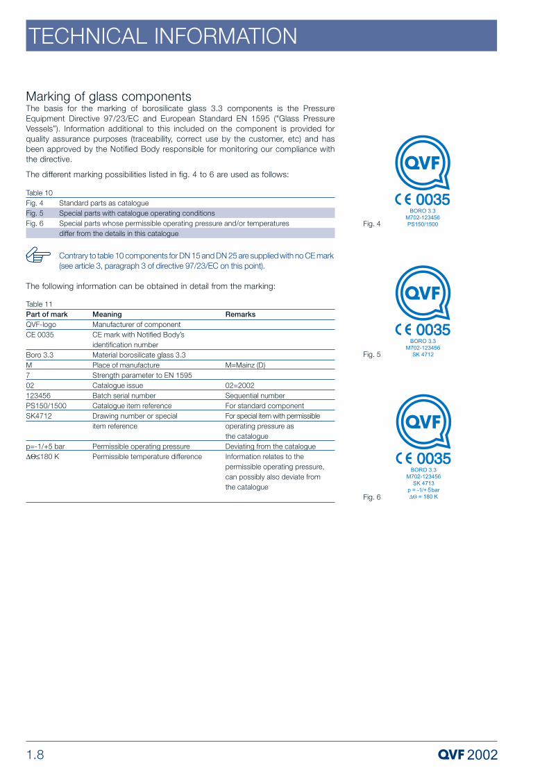
Table 10Fig. 4 Standard parts as catalogueFig. 5 Special parts with catalogue operating conditionsFig. 6 Special parts whose permissible operating pressure and/or temperatures
differ from the details in this catalogue
Table 11Part of mark Meaning RemarksQVF-logo Manufacturer of componentCE 0035 CE mark with Notified Body’s
identification numberBoro 3.3 Material borosilicate glass 3.3M Place of manufacture M=Mainz (D)7 Strength parameter to EN 159502 Catalogue issue 02=2002123456 Batch serial number Sequential numberPS150/1500 Catalogue item reference For standard componentSK4712 Drawing number or special For special item with permissible
item reference operating pressure as the catalogue
p=-1/+5 bar Permissible operating pressure Deviating from the catalogue∆Θ≤180 K Permissible temperature difference Information relates to the
permissible operating pressure, can possibly also deviate from the catalogue
Contrary to table 10 components for DN 15 and DN 25 are supplied with no CE mark(see article 3, paragraph 3 of directive 97/23/EC on this point).
Marking of glass componentsThe basis for the marking of borosilicate glass 3.3 components is the PressureEquipment Directive 97/23/EC and European Standard EN 1595 ("Glass PressureVessels”). Information additional to this included on the component is provided forquality assurance purposes (traceability, correct use by the customer, etc) and hasbeen approved by the Notified Body responsible for monitoring our compliance withthe directive.
The different marking possibilities listed in fig. 4 to 6 are used as follows:
The following information can be obtained in detail from the marking:
Fig. 4
Fig. 5
Fig. 6

1.9
TECHNICAL INFORMATION
Grooves in the fire-polished sealing surface in the DN 15 to DN 300 nominal sizerange securely locate the O-ring gasket in place and prevent it being pushed out bythe internal pressure.
Flexible gaskets (see Section 9 "Couplings”) facilitate deflections of up to 3° so thateven complicated systems can be laid out simply and securely.
•
•
Glass components with safety flat buttress end can be connected direct tospherical ended components by means of the glass or PTFE adaptors descri-bed in Section 2 "Pipeline Components”.
Safety flat buttress endsIn practice the buttress end areas of borosilicate glass components have to withstandnot only the tensile and compressive stresses resulting from being operated underpressure or vacuum, and the thermal stresses caused by the operating temperature,but also the stresses set up by the bolting forces in the coupling. Engineering a safebuttress end therefore involves ensuring that the sum of these stresses is minimised.The design of the flange coupling and the fire polished sealing surface both makesignificant contributions to this end.
The major dimensions of the safety flat buttress ends can be found in the table below,in conjunction with the illustrations alongside.
D1 16.826.538.550.576104.5154203300457614838 – 8161052 – 988
D228.642.257.47099.2132.6185235340528686.59201093
D323344860.588120.5172220321----
D415.5 – 17.525 – 2736.5 – 39.7548 – 5272 – 7897.6 – 110150 – 156197 – 205299 – 303444 – 456592 – 599799 – 805976 – 983
TypeAAAAAAABBCCCC
Table 12DN15254050801001502003004506008001000
All components with safety flat buttress ends produce positive and high performanceconnections ensuring safety in operation when used in conjunction with the couplingsdescribed in Section 9 "Couplings”. The following significant details are especiallynoteworthy in this context:
KF Pipe EndsIn addition to the safety flat buttress ends, QVF also supplies other pipe systems, suchas the ball/socket (KF) system from Schott. This pipe end enables deflection of theconnection without an additional joint element, and the systems is described fully inthe special supplement "KF Pipe Line Systems" including the accompanyingconnections and fittings. It offers full compatibility to the former Schott systemdescribed in catalogue 6076.
The dimensions are laid down in the special supplement.

1.10
TECHNICAL INFORMATION
Jacketed glass componentsThese borosilicate glass 3.3 components provide a solution that meets requirementsencountered in practice. They have proved their worth to excellent effect throughoutthe chemical and pharmaceutical industries as well as many related areas such asfood and drink production, dye works and the electroplating industry. They are usednot only to avoid heat loss for the purpose of saving energy but also where the producttemperature has to be maintained to prevent crystallising or undesirable reactions.This is achieved without losing the benefit of being able to monitor the process visually.
Jacketed versions of all the major glass components of our modular system areavailable. The range therefore includes not only pipeline components but also valvesand vessels as well as a wide variety of column components.
In the case of shorter pipe sections, fittings and spherical vessels up to 50 l nominalcapacity, the jacket is one-piece and welded at both ends. In all other cases, thedifferent linear expansion of the basic component and the jacket has to becompensated for by other means. On longer pipe sections the jacket is welded at bothends but it has a flexibly sealed expansion joint in the middle. On vessels it is weldedonly at the upper end and at the bottom it has a flexible seal.
The connections on the jacket are standard safety flat buttress ends. Further details onconnection options can be found in the respective product description.
Permissible operating conditionsThe permissible operating pressures for the inner part of jacketed components areidentical to those for their non-jacketed counterparts (see page 1.7). However,deviations will arise in the permissible operating temperatures for the inner part andthe permissible operating conditions in the jacket itself. These are caused by thepermanently flexible seal, which absorbs the different expansion levels of the innercomponent and the jacket, but does not have the high temperature resistance andstrength of borosilicate glass.
Permissible operating temperature: Taking into account a sufficiently high safety factor, the permissible operatingtemperature for the inner component is -80 ºC to +200 ºC and for the jacket it is -50ºC to +180 ºC. The maximum permissible temperature difference (∆Θ) between theinner and outer areas is 180 K.
Permissible operating pressure: The maximum permissible operating pressure in the jacket is +0.5 bar g up to anoverall heat transfer coefficient of u = 70Wm-2K-1. This average value can be expectedduring a heating process with thermal oil in the jacket and stirred liquid inside thevessel.
GMP-compliant installationsSpecial care is required in the selection of components and equipment for theconstruction of installations complying with GMP guidelines as regards their designand the materials of construction used. Because of its special properties, which arehighly valued in the pharmaceutical industry, and when used in conjunction withmaterials on the FDA-approved list such as glass lined steel (vessels, valves) and PTFE(bellows, linings, cladding) borosilicate glass 3.3 guarantees that the build-up ofdeposits is avoided in areas in contact with the product. Minimum dead space toensure complete draining and a capability for simple and effective cleaning areachieved by the design of the components, their layout and the selection of suitablevalves. Stainless steel coupling and support material is available (see Section 9"Couplings” and Section 10 "Structures & Supports”) for the design of complete unitscomplying with clean room conditions from the external aspect.
Jacketed components can be found in the appropriate section of this catalogue.

1.11
TECHNICAL INFORMATION
Protection against mechanical damageBorosilicate glass 3.3 components can be CORWRAP or Sectrans coated to protectthe glass surface against external damage such as scratching or impact. Both versionscan be applied to almost all glass components irrespective of their shape. Both haveexcellent resistance to chemicals and weathering. They present no health risk andheating them does not give rise to any unpleasant odours or gases.
External protection of borosilicate glass 3.3 pressure vessels against mechanicaldamage in working areas and areas subject to traffic can be provided by safetyscreens. The use of these is to be recommended and in some areas it is a legalrequirement (e.g. to comply with Point 9 of the TRB 801 Technical Regulations forPressure Vessels in Germany).
Coated and wrapped glass componentsSectrans is a highly transparent polyurethane-based coating that is applied to theglass component by spraying to a defined thickness. The permissible long-termoperating temperature for this material is 140 ºC, but it can also go up to 180 ºC forshort periods. Above 140 ºC the coating can turn yellow, but this has no adverse effecton its protection function and transparency.
All Sectrans coating is dissipative and may be used within Ex-areas.
In the event of the glass being broken, the Sectrans coating provides protectionagainst splintering. If no pressure is involved, limited protection against the productescaping is provided. However if the glass component is being used at the permissibleoperating pressure the contents can escape.
The coating incorporates UV protection so that it can be used for handlingphotosensitive substances.
The CORWRAP coating comprises of an impregnated glass fiber mat, which is cut tothe outer form of the glass and is wrapped in an overlapped fashion. This glass fiberreinforced polyester jacket is also almost transparent, yet it does not achieve thedegree of transparency of a Sectrans coating. The maximum permissible operatingtemperature for CORWRAP coated glass parts is about 150°C.
In case of glass fracture, the CORWAP coating also offers protection against splitters,and prevents the outflow of fluid at pressure-free operation.
In the event of the glass being broken, the GRP wrapping also provides protection againstsplintering and if no pressure is involved it prevents liquid escaping. Where low pressure isinvolved, there is limited protection against the product escaping which provides anemergency evacuation capability in the event of breakdown.
Coating or wrapping glass components does not increase their permissibleoperating pressure in any way.
When ordering Sectrans coated components the suffix "L” should be addedto the catalogue reference given in this catalogue, e.g. "PS100/500L”. ForGRP wrapped components the suffix "C” should be added, e.g. "PS100/500C”.
If CORWRAP coated glass parts are to be used in explosion rated areas of thecategory 1 or 2 (formerly zone 0 or 1), these shall be provided with a conduc-tive coating.
We would be happy to advise you on the basis of the regulatory requirementsapplicable in each particular case and the guidelines drawn up by ourselves for thedesign of GMP-compliant plant.

1.12
TECHNICAL INFORMATION
Safety screensSimple versions, such as wire mesh or expanded metal in box-section frames are ofcourse a low cost solution, but not user-friendly. This applies especially when the plantneeds protection on all sides. There is no doubt that it is better to use transparentplastic safety screens with frames that are self-supporting or fixed to the supportstructure and which can be equipped with covered service openings.
The best solution is to use safety screens consisting of medium flexibility transparentPVC which has a high resistance to abrasion. To ensure good lateral stability, thesehave galvanised metal strips bolted on at the top and bottom. Hooks are also fitted tothe top edge to enable the safety screen to be suspended from the structure.Swivelling versions and covered service openings guarantee optimum ease of use.The screens can be individually adapted to local conditions as they are subdivided intooverlapping sections.
For installations where electrostatic charges can be expected the screens can besupplied with an antistatic coating. This reduces the conductor resistance to less than10 8ž. The temperature of use of this material is between -40 and +40 ºC. It has limitedresistance to organic substances and adequate resistance to inorganic substances.
Glass Facilities Within Ex AreasIf ignition risks occur due to electrostatic charging during the operation of glassfacilities within explosion-endangered areas, relevant protective measures arenecessary, whose scope is aligned to the probability of occurrence for an explosion-capable environment. Details regarding the creation, assessment and prevention ofspark dangers due to electrostatic charging may be viewed in the regulation BGR 132edited by the German BG Chemistry.
The requirements of BGR 132 and the EU directive 94/9/EG have been implementedby QVF within a step-type safety concept so that the correct parts and safetymeasures may be chosen contingent to the zone type, explosion group, and theprocedure deployed. Thus, conductive PTFE and metal parts with earthing clips areavailable that are marked by a suffix "D" meaning "dissipative".
As the accumulation of charges in metal flanges must especially be avoided, thestandard usage of plastic flanges up to nominal diameters of DN 300 are of specialadvantage as these cannot accumulate explosive charge levels.
The Sectrans coating of glass is a standard product manufactured to be conductive,and may be deployed in ex areas. If one may expect dangerous charge accumulationon the glass surface in the course of a risk assessment, QVF offers a patented solutionfor the conductivity of the coated glass surfaces.
If it is necessary to earth metal parts this should be done by connecting them to anelectric protective conductor (drives etc) or by fitting conductive earthed points to thecomponents to be earthed. In the glass plant it is advisable not to earth all parts of theplant individually but to interconnect them in a continuous circuit. This can done bymeans of a main conductor located parallel to the column, pipeline etc to which thecomponents requiring earthing can be connected. By "earthing” it is to be understoodin this context that the conductor resistance,(i.e. the electrical resistance of theearthing between an electrode set up on one side and earth) is not greater than 106Ω.
Consideration of mechanical sources for sparks as required by the EU directive94/9/EG has been performed for QVF products. Drives with dual-action and single-action mechanical seals with ATEX conforming certificates are included.

1.13
TECHNICAL INFORMATION
Marking of electrical equipmentWith the introduction of EC directive 94/9/EC (ATEX 100a) additional marking ofequipment for use in explosive atmospheres is required. This indicates the area inwhich the equipment can be used, i.e. new EC test certificates (replacing theconformity certificates to directive 76/117/EEC) do not now contain any specialindication with regard to permissible use in a specific flameproof zone.
In process engineering installations, the relevant markings are "II 1G” and "II 2G” formeasurement and control instruments and "II 2G” for motors, where "II” means theappliance group (allowing the appliance to be used in any area except mining), "1” or"2” the category (formerly zone) and "G” (standing for gases and vapours) the type ofexplosive atmosphere.
As the marking prescribed by CENELEC, e.g. "EEx e II T4” or "EEx ia IIC T6” has beenretained and the information called for in ATEX 100a must be added, the full newmarking for this equipment is "II 2G EEx e II T4” or "II 2G EEx ia IIC T6”.
Risk analysis / residual risks All the components and apparatus in the 2002 edition of the QVF catalogue have beensubjected to a risk analysis in accordance with Directive 97/23/EC and thecorresponding countermeasures are documented by QVF. To exclude risks above andbeyond these resulting from improper use (Directive 97/23/EC, Appendix I, Section 1-3) the following points should be observed:
• Although borosilicate glass 3.3 is a material resistant to virtually all chemicalattack, alkaline solutions, hydrofluoric acid and concentrated phosphoric acid can cause some erosion. If there is any concern that there may be a reduction in wall thickness, the required minimum wall thickness should be checked at regular intervals.
• Unstable fluids, substances that can decompose, call for special safety precautions in the use of glass plant.
• The permissible operating conditions in accordance with section 1 the catalogue,page 1.6, should be observed and compliance ensured if necessary by means of additional measures such as pressure relief valves, bursting disks, over-fill preventi on or temperature limiters.
- Permissible operating pressures:The permissible operating pressure should be observed in every case, including when commissioning, checking for leaks and filling the plant.
- Permissible operating temperature:The maximum operating temperature for glass components is 200°C and this should be observed and where necessary, e.g. with electrical heating or exothermic reaction, ensured by the use of suitable measuring quipment.
- Permissible thermal shock:Borosilicate glass can withstand thermal shocks up to 120 K. For plants operating at temperatures in excess of 120 °C, and which are not protected by insulation, the thermal shock limit could be exceeded by cold water sprayed onto the equipment by a sprinkler system. To avoid this, sprinkler heads should not be mounted in the vicinity of unprotected glass process plant. In the event of a fire high temperatures may arise which could also result in breakage of the glass.
• Extra loads, such as reaction forces on side branches, are not permissible. Bellows should be included in interconnecting pipework to ensure a stress-free connection to the glass plant.
• Mechanical damage / protective measures:The tubular structure supporting the equipment or plant also provides protection against damage from external sources and prevents other items coming into contact with it.
Parts of the plant which are located outside the structure must be protected against mechanical damage.

1.14
TECHNICAL INFORMATION
Parts of the plant, which can reach a surface temperature higher than 60° C inoperation and which are located outside the support structure, must be provided with protection against contact.
Additional safety devices are available in the form of safety screens, spray guards, coated and wrapped glass components (see section 1 of the catalogue,pages 1.11 and 1.12).
• Damage to heat exchangers:Should damage occur to the coil batteries in coil type heat exchangers or the heat exchange tubes in shell and tube heat exchangers, the service fluid and product can become mixed.
Media, wich could react resulting in the generation of pressure and temperature (exothermic processes), should therefore be kept separate.

2 PIPELINE COMPONENTS
PROCESS PLANT COMPONENTSP 302 e.3 Copyright © 2007, QVF Engineering GmbH. All rights reserved.

2.2
PIPELINE COMPONENTS
IntroductionQVF borosilicate glass 3.3 pipeline is widely used in the chemical, pharmaceutical andallied industries together with other applications such as food and drink production, dyeworks and electroplating. This is because of the special properties of borosilicate glass3.3 and PTFE (gaskets) plus the fact that borosilicate glass 3.3 is an approved andproven material of construction for pressure vessels.
Reference should also be made in this context to the extreme reliability of the improved,strong and high-duty coupling system used for all components. This is achievedthroughout the whole range of nominal sizes by the use of the safety buttress end whichhas been designed specifically by taking into account the properties of the materialcombined with a reliable flange system.
The complete range of standard pipeline components is described on the followingpages. Non-standard components can also be supplied to special order.
A detailed listing of all catalogue components by »Description« and »Reference« can befound in the »Index«.
Many of the components listed in this section are not only used in pipelines but also usedin the design of process plant. For example pipe sections are used in columns, feedpipes are fitted in reducing tee pieces and reducers are also used as the top or bottomcomponent in columns.
Detailed information on a number of the topics referred to in the followingpages can be found in Section 1 »Technical Information«.
A deviation of up to 3º can be achieved by using the flexible gaskets describedin Section 9 »Couplings« which considerably simplifies the design andinstallation of complicated pipeline systems.
Details of the design of the different types of optimised buttress ends areillustrated alongside.
Metric grid modular systemThe pipeline components in the DN 15 to DN 150 nominal size range (pipe sections alsoup to DN 1000) described in this section comply with EN 12585 "Pipeline and Fittings,Compatibility and Interchangeability” and are conceived as a modular system. The onlyexception to this is the side branch on some reducing tee pieces. The basic unit ofmeasurement is 25 mm and all component dimensions are a multiple of this basic length.The resultant metric grid system facilitates trouble-free design and installation of systemswith these components.
In addition, all fittings and valves (please see Section 3 »Valves & Filters«) in the samenominal size always have the same limb length, so that bends can be interchanged withtee pieces or tee pieces with valves etc. This means that any modifications which maybe required to existing pipelines can be carried out quickly and easily.
GMP compliant installationsThe layout of pipelines when designing plant and equipment complying with GMPregulations calls for special care in both the planning and selection of the components,together with the materials of construction used for them. Borosilicate glass 3.3 has anumber of special properties that are highly valued in the pharmaceutical industry andthese, in conjunction with PTFE materials (gaskets) approved in accordance with theFDA catalogue, ensure that any build-up of unwanted deposits is avoided in areas whichcome in contact with the product. A design without any dead space, which ensures thatcomponents drain fully and can be cleaned easily and effectively, is achieved by theshape of the components and the way they are installed. Where the external surfacesof the pipeline have to comply with clean room requirements,appropriate stainless steelcoupling and support material can be supplied (please see Section 9 "Couplings” andSection 10 »Structures and Supports«).

2.3
PIPELINE COMPONENTS
Components suitable for higher permissible operating conditions can be supplied on request.
We would be happy to advise you on the basis of the regulatory requirements applicableto a particular case and the guidelines drawn up by ourselves for the design of GMPcompliant plant.
Horizontally installed pipelineWhereas vertical pipelines only have to support their own weight, bow can also occurin horizontal lines as a result of the additional weight of the liquids they contain. To reducethe resultant stress to a permissible level, supports should be provided at adequateintervals. The maximum spacing of these is indicated in Section 10 »Structures andSupports« as a function of the density ρ of the product being conveyed.
Coated pipeline componentsDamage to borosilicate glass 3.3 components resulting from accidental external causescannot be entirely excluded, especially in the smaller nominal sizes. This is primarily dueto the relatively rigorous conditions prevalent in production plants and applies especiallywhere no additional protection is provided in the form of insulation.
Our answer to this problem is to provide borosilicate glass 3.3 pipeline components witha Sectrans transparent coating. This can be applied irrespective of the shape of thecomponent and it provides additional protection without having any adverse effect onvisual monitoring of the process.
A glass fibre reinforced polyester coating providing a higher level of protection can alsobe supplied on request. This does have a slightly adverse effect on the transparency ofthe glass, making it translucent and not transparent.
Permissible operating conditionsWhile the maximum permissible operating temperature for all borosilicate glass 3.3pipeline components is generally 200 ºC (³Q • 180 K), the maximum permissible operatingpressure is governed by the main nominal size of the component but not by its shape.Detailed information on this and the operation of jacketed components can be found inSection 1 »Technical Information«.
The permissible operating conditions for components in other materials can be foundin the respective product description.
The drainline piping systemFor drainage, venting and dye lines, we recommend our beaded end borosilicate glass3.3 drainline piping as an especially economical solution. All components can be used up to a maximum permissible operating pressure of 0.5 bar g.

2.4
PIPELINE COMPONENTS
Pipe sections are used not only in pipeline systems but also in the design of columns.
For example, pipe sections with »LBE..« type packing supports (please see Section 6»Column Components«) clamped between the ends provide a larger free cross-sectionthan the combination of column section and built-in packing support. Increased packed heights can be achieved by installing a pipe section on top of a columnsection.
Precision bore pipe sections with tight tolerances for chromatography columnsand special column internals are listed in Section 6 »ColumnComponents«.
The end form, which depends on the nominal size, is shown in thediagram on page 2.2. Further information can be found in Section 1»Technical Information«.
ReferenceDN50-PS50/100PS50/125PS50/150PS50/175PS50/200PS50/300PS50/400PS50/500PS50/700PS50/1000PS50/1500PS50/2000PS50/3000
ReferenceDN 40-PS40/100PS40/125PS40/150PS40/175PS40/200PS40/300PS40/400PS40/500PS40/700PS40/1000PS40/1500PS40/2000PS40/3000
ReferenceDN25PS25/75PS25/100PS25/125PS25/150PS25/175PS25/200PS25/300PS25/400PS25/500PS25/700PS25/1000PS25/1500PS25/2000PS25/3000
ReferenceDN15PS15/75PS15/100PS15/125PS15/150PS15/175PS15/200PS15/300PS15/400PS15/500PS15/700PS15/1000PS15/1500PS15/2000-
L751001251501752003004005007001000150020003000
L1251501752003004005007001000150020003000
ReferenceDN150-PS150/150PS150/175PS150/200PS150/300PS150/400PS150/500PS150/700PS150/1000PS150/1500PS150/2000PS150/3000
ReferenceDN100-PS100/150PS100/175PS100/200PS100/300PS100/400PS100/500PS100/700PS100/1000PS100/1500PS100/2000PS100/3000
ReferenceDN80PS80/125PS80/150PS80/175PS80/200PS80/300PS80/400PS80/500PS80/700PS80/1000PS80/1500PS80/2000PS80/3000
L300500100015002000
ReferenceDN450-PSN450/500PSN450/1000PSN450/1500PSN450/2000
ReferenceDN300PS300/300PS300/500PS300/1000PS300/1500PS300/2000
ReferenceDN200PS200/300PS200/500PS200/1000PS200/1500PS200/2000
L50010001500
ReferenceDN1000-PS1000/1000PS1000/1500
ReferenceDN800-PS800/1000PS800/1500
ReferenceDN600PSN600/500PSN600/1000PSN600/1500
PIPE SECTIONS

2.5
PIPELINE COMPONENTS
SPACERSVariations in length can be accommodated by having pipe sections specially made tothe appropriate length. A simple alternative is, however, to use spacers. These are fittedbetween the ends of the adjacent components using an additional gasket and bolts ofthe appropriate length.
L10152025505075
ReferenceDN50SS50/10SS50/15SS50/20SS50/25-SS50/50SS50/75
ReferenceDN40SS40/10SS40/15SS40/20SS40/25-SS40/50SS40/75
ReferenceDN25SS25/10SS25/15SS25/20SS25/25SS25/50--
ReferenceDN15SS15/10SS15/15SS15/20SS15/25SS15/50--
TypeAAAABAA
L101520255075100100125
TypeAAAAAAAAA
ReferenceDN80SS80/10SS80/15SS80/20SS80/25SS80/50SS80/75SS80/100--
ReferenceDN100SS100/10SS100/15SS100/20SS100/25SS100/50SS100/75-SS100/100SS100/125
ReferenceDN150SS150/10SS150/15SS150/20SS150/25SS150/50SS150/75-SS150/100SS150/125
ADAPTORS-PTFEThese components can be used up to a maximum operating temperature of 130 ºC.They carry out parallel duties: they provide a trouble-free method of connectingcomponents with safety buttress ends to the KF system and they also act as gaskets.Adaptors should always be installed with the location collar on the safety buttress end.
The KF buttress end requires a different type of coupling. For further information please contact our Sales Department.
The borosilicate glass 3.3 adaptors described on page 2.6 supplementthese PTFE adaptors for larger nominal sizes and higher operatingtemperature.
ReferenceKRT15KRT25KRT40KRT50KRT80
DN1525405080
L678810

2.6
PIPELINE COMPONENTS
ADAPTORS-GLASSIn the larger nominal sizes and at higher operating temperatures, when the »KRT..«adaptors described on page 2.5 cannot be used, »AMS..« or »AFS..« adaptors madeof borosilicate glass 3.3 should be used.
Couplings for the safety buttress end of the adaptors can be found in Section 9 »Couplings«. The KF buttress end requires a different type of coupling. For further information please contact our Sales Department.
DN1525405080100150200300
ReferenceType BAFS15AFS25AFS40AFS50AFS80AFS100AFS150AFS200AFS300
ReferenceType AAMS15AMS25AMS40AMS50AMS80AMS100AMS150AMS200AMS300
REDUCERSThere are both concentric and eccentric versions of these components available tocomply with the varying requirements encountered in practice. In DN 150 nominal size andabove the basic form of these components is hemispherical.
The concentric version should always be used for preference in vertical installations.
Eccentric reducers are very frequently used in horizontal pipelines where there is achange of bore to enable them to drain completely. There can also be a requirement forthis version for design reasons, e.g. where there is a change of lateral alignment.
The end form, which depends on the nominal size, is shown in the diagramon page 2.2. Further information can be found in Section 1 »TechnicalInformation«.
L7575100100125150150150200

2.7
PIPELINE COMPONENTS
REDUCERS
ReferencePR25/15PR40/15PR40/25PR50/15PR50/25PR50/40PR80/25PR80/40PR80/50PR100/25PR100/40PR100/50PR100/80PR150/25PR150/40PR150/50PR150/80PR150/100PR200/25PR200/40PR200/50PR200/80PR200/100PR200/150PR300/25PR300/40PR300/50PR300/80PR300/100PR300/150PR300/200PR450/50PR450/80PR450/100PR450/150PR450/200PR450/300PR600/50PR600/80PR600/100PR600/150PR600/200PR600/300PR800/80PR800/100PR800/150PR800/200PR800/300PR1000/300PRN1000/450PRN1000/600
L100100100100100100125125125150150150150200200200200200175175175200200200225225225250250275250325325350350325325375375400425400400550550575550550650650650
Concentric ReducersDN1151525152540254050254050802540508010025405080100150254050801001502005080100150200300508010015020030080100150200300300450600
DN254040505050808080100100100100150150150150150200200200200200200300300300300300300300450450450450450450600600600600600600800800800800800100010001000

2.8
PIPELINE COMPONENTS
ReferencePRE25/15PRE40/25PRE50/25PRE50/40PRE80/25PRE80/40PRE80/50PRE100/25PRE100/40PRE100/50PRE100/80PRE150/50PRE150/80PRE150/100
Eccentric ReducersDN115252540254050254050805080100
L100100100100125125125150150150150200200200
L15612624181239332715524025
REDUCERS
DN25405050808080100100100100150150150
ReferencePBR40/25PBR50/40PBR80/50PBR100/50PBR100/80PBR150/50PBR150/80PBR200/80PBR300/80PBR300/150
DN1254050508050808080150
DN405080100100150150200300300
These items are an alternative to using a reducer plus a 90º bend. This saves one gasketand coupling and also reduces the overall length required.
The end form, which depends on the nominal size, is shown in the diagramon page 2.2. Further information can be found in Section 1 »TechnicalInformation«.
L125150150200200200250250300350
L1100150150150175150175175175250
90º BEND REDUCERS

2.9
PIPELINE COMPONENTS
ReferencePB90/15PB90/25PB90/40PB90/50PB90/80PB90/100PB90/150PB90/200PB90/300
L50100150150200250250300400
DN1525405080100150200300
BENDSBends are available in a variety of angles to suit different applications. This applies, forexample, to 10º and 80º bends whose uses include connections to reflux dividers(please see Section 6 »Column Components«) and thin film evaporators.
Bends up to and including DN 150 nominal size are supplied as "swept bends”, and inthe larger nominal sizes "mitred bends”.
In addition to the standard range specified below, bends of other angles andin larger nominal sizes can also be supplied on request.
Bends with thermometer branch can be found on page 2.11.
The end form, which depends on the nominal size, is shown in the diagramon page 2.2. Further information can be found in Section 1 »TechnicalInformation«.
BENDS90º Bends

2.10
PIPELINE COMPONENTS
BENDS
ReferencePB45/15PB45/25PB45/40PB45/50PB45/80PB45/100PB45/150PB45/200PB45/300
L5075100100125175200200200
DN1525405080100150200300
ReferencePB80/25PB80/40PB80/50PB80/80PB80/100
L100150150200250
DN25405080100
BENDS80° Bends
45° Bends

2.11
PIPELINE COMPONENTS
DN1252525252525
DN5080100150200300
ReferencePBT50PBT80PBT100PBT150PBT200PBT300
This is a version of the 90° bend that allows a thermometer or measuring probe to beinserted axially into a line (please see Section 8 »Measurement & Control«).
The end form, which depends on the nominal size, is shown in the diagramon page 2.2. Further information can be found in Section 1 »Technical Information«.
L150200250250300400
L1225280330340450525
L5075100125150
DN25405080100
ReferencePB10/25PB10/40PB10/50PB10/80PB10/100
10° BendsBENDS
90° BENDS WITH THERMOMETER BRANCH
2.12
PIPELINE COMPONENTS
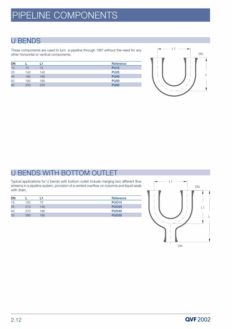
U BENDS
ReferencePU15PU25PU40PU50PU80
L75140180180200
DN1525405080
U BENDS WITH BOTTOM OUTLET
L125210270280
DN15254050
ReferencePUO15PUO25PUO40PUO50
These components are used to turn a pipeline through 180º without the need for anyother horizontal or vertical components.
L175140180180230
Typical applications for U bends with bottom outlet include merging two different flowstreams in a pipeline system, provision of a vented overflow on columns and liquid sealswith drain.
L175140180180

2.13
PIPELINE COMPONENTS
EQUAL TEE PIECES
ReferencePT15PT25PT40PT50PT80PT100PT150PT200PT300
L50100150150200250250300400
DN1525405080100150200300
Equal tee pieces are used for junctions in pipelines of the same nominal size. They havethe same limb length as 90º bends.
The end form, which depends on the nominal size, is shown in the diagram onpage 2.2. Further information can be found in Section 1 »Technical Information«.
CROSS PIECES
ReferencePX15PX25PX40PX50PX80PX100PX150
L50100150150200250250
DN1525405080100150
Cross pieces are important components in complex systems of interconnecting pipeline.

2.14
PIPELINE COMPONENTS
UNEQUAL TEE PIECES
DN2540505080808010010010010015015015015015020020020020020030030030030030030045045060060080080010001000
ReferencePTU25/15PTU40/25PTU50/25PTU50/40PTU80/25PTU80/40PTU80/50PTU100/25PTU100/40PTU100/50PTU100/80PTU150/25PTU150/40PTU150/50PTU150/80PTU150/100PTU200/40PTU200/50PTU200/80PTU200/100PTU200/150PTU300/40PTU300/50PTU300/80PTU300/100PTU300/150PTU300/200PTU450/80PTU450/150PTU600/150PTU600/300PTU800/150PTU800/300PTU1000/150PTU1000/300
Unequal tee pieces are mainly used in the design of columns and at junctions betweenpipelines of different nominal sizes.
In addition to the standard range specified below, unequal tee pieces can also be supplied with other nominal size side branches on request.
L15020020020025025025025025025030025025025030030025025030030040040040040040050060040050060080070010007001000
L1757580100100100115110125125150150150150175200175175200225250225225240275300275325375450500575650675750
The end form, which depends on the nominal size, is shown in the diagramon page 2.2. Further information can be found in Section 1 »TechnicalInformation«.
DN115252540254050254050802540508010040508010015040508010015020080150150300150300150300

2.15
PIPELINE COMPONENTS
Y PIECES
DN1--25-25---
DN15254040505080100
ReferencePY15PY25PY40/25PY40PY50/25PY50PY80PY100
These components are used in a similar way to U bends with a bottom outlet for merging two different flow streams in a pipeline system and also for incorporating measuring probes in vertical pipelines.
L125200225250250300350450
L1701069212499141177247
TypeAABABAAA
L2 5198326101332352
CLOSURES
ReferencePBE15PBE25PBE40PBE50PBE80PBE100PBE150PBE200PBE300
L40757510095145125120170
DN1525405080100150200300
Where branches have to be closed off, closures should be used together with a standard coupling. If frequent access to a branch is required, a quick release couplingshould be used instead (please see Section 9 »Couplings«).
In nominal size DN 200 and above, closures are supplied in the hemispherical end version.
The end form, which depends on the nominal size, is shown in the diagramon page 2.2. Further information can be found in Section 1 »Technical Information«.

2.16
PIPELINE COMPONENTS
HOSE CONNECTORS
HOSE CONNECTORS
Reference
PHC15/10PHC15/13PHC15/16PHC15/18PHC15/20PHC25/20PHC25/26PHC40/26PHC40/42
hose-iØd101316182020262642
DN
151515151525254040
Hose connectors are used to connect flexible lines (hoses) for such purposes as to draina unit, to carry cooling water to and from heat exchangers or for heatingjacketed components. The internal diameter of the hoses should be as indicated in thetable below to avoid fixing and leakage problems.
In the case of long and/or heavy hoses, 90º hose connectors should beused to reduce the bending moment on the connecting branches.
L
7070110707090110100110
Straight Hose Connectors

2.17
PIPELINE COMPONENTS
HOSE CONNECTORS
Reference
PHC90/15/16PHC90/15/18PHC90/15/20PHC90/25/20PHC90/25/26
hose-iØd1618202026
DN
1515152525
L
6060606070
L1
6060608080
METAL HOSE CONNECTORS
Reference
PMC15/13PMC25/20PMC50/42
hose-iØd132042
DN
152550
L
507090
L1
101540
The use of these hose connectors, manufactured from stainless steel, is recommendedwhere there is a requirement for connecting flexible hoses containing heat transfer fluids at elevated temperatures to jacketed components, or long and/or heavyhoses containing coolant to heat exchangers.
Metal hose connectors are supplied complete with the flange, insert, gasket andfastenings necessary to connect to the glass branch in question.
90º Hose Connectors
2.18
PIPELINE COMPONENTS
JACKETED COMPONENTSJacketed components provide a means of heating and cooling pipeline systems.Jacketed versions of pipe sections, bends and tee pieces are available as standardcomponents up to DN 80 inclusive. In the case of fittings and shorter pipe sections (upto L = 500 mm) the jacket is one-piece and welded at both ends. On longer pipesections, because of differences in linear expansion between the inner component andthe jacket, we incorporate a split design with a flexible seal.
In addition to the standard components listed below, pipe sections of other lengths andlarger nominal sizes (up to DN 300 ) together with fittings up to DN 150 are also available.
The permissible operating conditions for the jacket and inner componentcan be found in Section1 "Technical Information”.
The branches on the jacket are of the QVF safety buttress end type. If theyare aligned horizontally with long or heavy hoses connected to them, werecommend 90º hose connectors to reduce the bending moment on thebranches.
Borosilicate glass 3.3 and metal hose connectors can be found on pages2.16 and 2.17 and hoses in Section 9 »Couplings«.
Components can also be supplied on request with jackets extending up tothe buttress end. Further details of these can be found in Section 1 »Technical Information«.

2.19
PIPELINE COMPONENTS
ReferenceDPS15/200DPS15/300DPS15/400DPS15/500DPS15/700DPS15/1000DPS15/1500DPS15/2000
DPS25/200DPS25/300DPS25/400DPS25/500DPS25/700DPS25/1000DPS25/1500DPS25/2000
DPS40/300DPS40/400DPS40/500DPS40/700DPS40/1000DPS40/1500DPS40/2000
DPS50/300DPS50/400DPS50/500DPS50/700DPS50/1000DPS50/1500DPS50/2000
DPS80/300DPS80/400DPS80/500DPS80/700DPS80/1000DPS80/1500DPS80/2000
DN11515151515151515
1515151515151515
15151515151515
15151515151515
15151515151515
DN1515151515151515
2525252525252525
40404040404040
50505050505050
80808080808080
L200300400500700100015002000
200300400500700100015002000
300400500700100015002000
300400500700100015002000
300400500700100015002000
L26565656565656565
7575757575757575
80808080808080
85858585858585
100100100100100100100
TypeAAAABBBB
AAAABBBB
AAABBBB
AAABBBB
AAABBBB
L15050505050505050
6565656565656565
65656565656565
70707070707070
90909090909090
Pipe SectionsJACKETED COMPONENTS

2.20
PIPELINE COMPONENTS
JACKETED COMPONENTS
ReferenceDPB90/15DPB90/25DPB90/40DPB90/50DPB90/80
DN11515151515
DN1525405080
L75100150150200
°L26070758095
L15065657090
ReferenceDPB45/15DPB45/25DPB45/40DPB45/50DPB45/80
DN11515151515
DN1525405080
L75100100100125
L26070758095
L15065657090
JACKETED COMPONENTS
90º Bends
45º Bends
2.21
PIPELINE COMPONENTS
JACKETED COMPONENTS
ReferenceDPT25DPT40DPT50DPT80
DN115151515
DN25405080
L100150150200
L2758085100
L165657090
ReferenceDPTU25/15DPTU40/25DPTU50/25DPTU50/40DPTU80/25DPTU80/40DPTU80/50
DN115252540254050
DN25405050808080
DN215151515151515
L165657070909090
L100100125125150150150
JACKETED COMPONENTS
L275808585100100100
L365757575758085
L450656565656570
Tee Pieces
Unequal Tee Pieces

3 VALVES & FILTERS
PROCESS PLANT COMPONENTSP 303 e.3 Copyright © 2007, QVF Engineering GmbH. All rights reserved.

3.2
VALVES & FILTERS
IntroductionQVF valves can be relied upon to require minimum maintenance and to provide maximum reliability in service. They are widely used in the chemical, pharmaceutical andallied industries together with other applications such as food and drink production, dye works and electroplating. This is because of the special properties ofborosilicate glass 3.3, PTFE, PFA, ceramic and tantalum plus the fact that borosilicateglass 3.3 is an approved and proven material of construction for pressure vessels.
Reference should also be made in this context to the extreme reliability of the improved,strong and high-duty coupling system used for all components. This is achievedthroughout the whole range of nominal sizes by the use of the safety buttress end whichhas been designed specifically by taking into account the properties of the materialcombined with a reliable flange system.
The complete range of standard valves is described on the following pages. Non-standard versions can also be supplied to special order where indicated in the productdescription.
A detailed listing of all valves by »Description« and »Catalogue Reference« can be foundin the »Index«.
Detailed information on a number of the topics referred to in the followingpages can be found in Section 1 »Technical Information«.
Metric grid modular systemThe valves described in this section comply with EN 12585 "Pipeline and Fittings,Compatibility and Interchangeability” and are conceived as a modular system. The onlyexceptions to this are »RKP..« non-return valves and »FVT..« butterfly valves. The basicunit of measurement is 25 mm and all component dimensions are a multiple of this basiclength. The resultant metric grid system facilitates trouble-free design and installation ofsystems with these components.
In addition valves and fittings (please see Section 2 »Pipeline Components«) in the samenominal size always have the same limb length, therefore the valves can be interchangedwith bends, tee pieces etc. This means that any modifications which may be requiredto existing pipelines can be carried out quickly and easily.
Sealing in Accordance with TA LuftThe former German regulation "Technical Manual for Clean Air" (TA-Luft) was amended,and the updated version came into force on 2004-07-24. It contains maximumpermissible limits for dust, steam, or gas emissions during the processing, conveying,or re-filling of dust, fluid, or gas materials.
TA Luft requires high-grade sealed metal bellows with a subsequent safety gland orequivalent sealing system for closing or control devices for the sealing of spindle feed-throughs. Equivalent sealing systems are deemed necessary if temperature-specificleakage rates are complied with during the proof procedure in accordance with VDI2440.
As metal bellows for QVF fittings are ruled out due to corrosion reasons, the equivalencetest was put to proof by TÜV Rhineland / Berlin-Brandenburg during the course ofdesign inspections.
All hand operated borosilicate glass 3.3/PTFE valves are, therefore, fitted with asecondary seal in addition to the basic bellows seal. Pneumatically actuated on/offvalves and control valves alone are available in two alternative versions. Butterfly valvesand ball valves are fitted with a secondary seal.

3.3
VALVES & FILTERS
Valves with PTFE bellows suitable for higher permissible operating pressurescan also be supplied on request.
Where different operating conditions apply to individual valves, the relevantdetails are provided in the respective product description.
GMP compliant installationsThe use of valves and the layout of interconnecting pipeline incorporating valves whendesigning plant and equipment complying with GMP regulations, calls for special carein both the planning and selection of the components, together with the materials ofconstruction used for them. Borosilicate glass 3.3 has a number of special propertiesthat are highly valued in the pharmaceutical industry, and these, in conjunction with PTFEmaterials (bellows, linings) approved in accordance with the FDA catalogue, ensure thatany build-up of unwanted deposits is avoided in areas which come in contact with theproduct. A design without any dead space, which ensures that components drain fullyand can be cleaned easily and effectively, is achieved in many valves by their shape andthe way they are installed. Where the external surfaces of these components have tocomply with clean room requirements, appropriate stainless steel coupling and supportmaterial can be supplied (please see Section 9 »Couplings« and Section 10 »Structuresand Supports«).
We would be happy to advise you on the basis of the regulatory requirements applicableto a particular case, and the guidelines drawn up by us, for the design of GMP compliantplant.
Coated valvesDamage to borosilicate glass 3.3 valves resulting from accidental external causescannot be entirely excluded, especially in the smaller nominal sizes. This is primarily dueto the relatively rigorous conditions prevalent in production plants and appliesespeciallywhere no additional protection is provided in the form of insulation.
Our answer to this problem is to provide borosilicate glass 3.3 valve bodies with aSectrans transparent coating. This can be applied irrespective of the shape of thecomponent and it provides additional protection without having any adverse effect onvisual monitoring of the process.
A glass fibre reinforced polyester coating providing a higher level of protection can alsobe supplied on request. This does have a slightly adverse effect on the transparency ofthe glass, making it translucent and not transparent.
Permissible operating conditions
While the maximum permissible operating temperature for borosilicate glass 3.3 valvebodies is generally 200 ºC (≥Θ •180 K) and their maximum permissible operating pressureis the same as for pipeline components of the same nominal size, the incorporation ofbellows imposes certain restrictions and the maximum permissible operating pressurefor the complete valve is somewhat lower. When the valves are used in plant applicationsthis is unlikely to be a problem since the maximum permissible operating pressure ofthe plant as a whole is governed bythe components with the largest nominal size.Detailed information on this and the peration of jacketed valves can be found in Section1 »Technical Information«.

3.4
VALVES & FILTERS
The design (bellows plug and seat shape) of the manually operated valves describedbelow is such that they can be used both as on/off valves and for the coarse regulationof liquid flow, for example in pump delivery lines. If required, on/off valves can also besupplied in the DN100 and DN150 nominal sizes but without regulating cone.
Manually operated control valves can be found on page 3.13 and on/off and controlvalves with pneumatic actuators are described from page 3.10 and 3.14.
These valves only act as regulating valves when the direction of flow is towardsthe cone.
DN1525405080
L125175225300375
H120220285295430
H190170215225320
ReferencePVD15PVD25PVD40PVD50PVD80
ON/OFF VALVES WITH REGULATING PLUG
ON/OFF VALVES WITH REGULATING PLUG Straight Through Valves

3.5
VALVES & FILTERS
ON/OFF VALVES WITH REGULATING PLUG
DRAIN VALVESThese valves have a hose connector at the outlet so that a hose can be connected tothem easily and securely. The internal diameter of the hoses should be as indicated inthe table below to avoid fixing and leakage problems.
Reference
PVA25/16PVA40/16PVA40/26
DN
254040
hose Ød161626
L
140150200
H
120120223
H1
9292170
DN1525405080
L50100150150200
H85170215210290
ReferencePED15PED25PED40PED50PED80
Angle Valves

3.6
VALVES & FILTERS
VENT VALVESThese valves are ideal for venting plant operating under vacuum, at atmosphericpressure or at low positive pressure (up to 0.5 bar g). In all other cases we recommendthe use of the drain valves as described on page 3.5.
DN152540
ReferencePVL15PVL25PVL40
JACKETED ON/OFF VALVESIn addition to pipe sections and pipeline fittings (see Section 2 »Pipeline Components«)jacketed valves with regulating plug can also be supplied for pipeline systems involvingtemperature control. Further versions of the valves described here are also available onrequest.
These jackets are one-piece and sealed at both ends. They are designed to ensure thatthe critical area in particular, i.e. the valve seat, can be maintained at a given temperature.The less critical pipe ends can be heated separately by a suitable method.
Details of the permissible operating conditions for the inner and outer area canbe found in Section 1 »Technical Information«.
The branches on the jacket are of the safety buttress end type. If they arealigned horizontally and if long hoses or heavy hoses are connected to them,we recommend 90º hose connectors to reduce the bending moment on thebranches.
In the case of the DN 15 angle valves the branches on the jacket are positionedturned through 90º to the front (DN 1) and back (DN 3) respectively.
Borosilicate glass 3.3 and metal hose connectors can be found in Section 2»Pipeline Components« and hoses in Section 9 »Couplings«.
d101010
H132140145

3.7
VALVES & FILTERS
JACKETED ON/OFF VALVES
JACKETED ON/OFF VALVES
ReferenceDPVD15DPVD25DPVD40DPVD50
L125175225300
L16590115150
L245606575
L37195129145
L4224964107
H128235285310
H198179217231
Straight Through Valves
Angle Valves
DN115151515
DN15254050
ReferenceDPED15DPED25DPED40DPED50
DN2-151515
DN315---
L50100150150
L1-202555
L2- 858585
L365709095
L457118177185
L5 37---
H97185215226
DN115151515
DN15254050

3.8
VALVES & FILTERS
ReferencePVF15APVF25APVF40APVF50A
L50100150150
H161155190190
LOADING VALVES
DN15254050
ReferenceNRV15NRV25NRV40NRV50NRV80
DN15050808080
DN1525405080
The function of these valves is to ensure that flow in vertical pipelines can only be in one direction. The PTFE seat, ball and retaining plate provide excellent corrosion resistance.
Where there is an increased requirement for freedom from leakage these valves can besupplied on request with an O-ring gasket.
Ball-type non-return valves are not suitable for use as a long-term shut-offfunction.
d12323484848
L225225325325325
BALL-TYPE NON-RETURN VALVES
These valves are used to maintain a constant pressure and are recommended for useafter dosing pumps. They may, however, also be used on occasions with centrifugalpumps (in this application it is more usual to use an orifice plate).
They can thus be used to deliver liquids safely, into or out of a vacuum, for example.Their use as by-pass valves in conjunction with dosing pumps prevents the build-up ofan unacceptably high pressure in the event of the pressure-side pipeline beinginadvertently closed off.
Unlike manually operated types, this valve has a spring the tension of which can beadjusted by a screwdriver. Thus, all intermediate values between 0.5 bars and thepermissible operating over-pressure may be set a tolerance range of ± 0.3 bar.
Please specify pressure setting on the order.
Care should be taken when operating these valves to ensure that the sum ofthe setting pressure and the pressure drop in the valve does not exceed themaximum permissible operating pressure of the pipeline.
Loading valves should not be used as pressure relief valves as they do not havethe necessary approval for such applications.

3.9
VALVES & FILTERS
TYPE RK NON-RETURN VALVESUnlike PTFE flap type non-return valves (please see below), this version provides a largefree cross-section even in small nominal sizes and consequently ensures low pressuredrop. It is suitable for liquids and installation in horizontal and vertical pipelines.
The PTFE flaps are mounted on tantalum hinges which must be located at the top wheninstalled in horizontal lines.
If required we can supply a version with drain branch and an eccentric design which isused with a »PRE..« (please see Section 2 »Pipeline Components«).
Flap-type non-return valves are not suitable for use to provide a long-termshut-off function.
TYPE RKP NON-RETURN VALVES
ReferenceRK25RK40RK50
DN15080100
DN254050
L225275325
These PTFE flap-type non-return valves are only available in larger nominal sizes (pleasesee also type »RK..« non-return valves above). They can be fitted in horizontal or verticalpipelines using longer coupling bolts. No additional gaskets are required.
The PTFE flaps are mounted on tantalum hinges which must be located at the topwheninstalled in horizontal lines.
The maximum permissible operating temperature for these flap-type non-return valves is 130 °C. The permissible operating pressure is the sameas for pipeline components of the same nominal size.
The valve body is manufactured from carbon filled PTFE.
Flap-type non-return valves are not suitable for use to provide a long-termshut-off function.
ReferenceRKP50RKP80RKP100RKP150
d305582125
DN5080100150
L24242425

3.10
VALVES & FILTERS
PNEUMATICALLY ACTUATED ON/OFF VALVES These valves consist of the valve body and bellows plug used in our manually operatedstraight through and angle valves combined with either a Kämmer or Samson pneumaticdiaphragm actuator.
All the types specified below are available in two versions, the only difference being thetype of seal to atmosphere provided. Thus catalogue reference »PVS25 /..« for exampledescribes a valve with single seal (between the valve body and the diaphragm actuator),while catalogue reference »PVS25S /..« applies to a valve with a double seal inaccordance with TA-Luft (an additional spindle seal in the intermediate flange below theyoke rods as a precaution in case the bellows ruptures. Please see also page 3.2). Inthis case the Kämmer actuator must also be fitted with intermediate flange and yokerods.
To provide a means of supporting the valves a »KK50-5« structure fitting (please seeSection 10 »Structures & Supports«) is provided on one of the yoke rods to facilitateattachment to the support structure. In the case of valves without yoke rods (Kämmeractuator with single seal) a special support is part of the supply.
The required supply pressure is 2.5 bar g for all actuators and this should notbe exceeded by more than 10%.
When ordering please add »1« to the catalogue reference for »spring to open«and »2« for »spring to close«.
If required Samson actuators can be supplied with the following additionalbuilt-on features:
- Limit switch with built-in inductive proximity switch, manufactured to protection type II 2 G EEx ia IIC T6, in order to signal its opening / closing position.
- 3/2 way solenoid valve manufactured to protection type II 2 G EEx ia IIC T6(24 VDC).
Kämmer actuators can be supplied with the following additional built-on features on request:
- Built-in inductive proximity switch, manufactured to protection type II 2 G EEx ia IIC T6, in order to signal its opening / closing position.
- Built-in analog-signal position feedback manufactured to protection type II 2 G EEx ia IIC T6 (4...20 mA). This component can only be deployed as asubstitute to the previously mentioned proximity switch.

3.11
VALVES & FILTERS
D150150205205205205300300
DN2525404050508080
ReferencePVM25/...PVM25S/...PVM40/...PVM40S/...PVM50/...PVM50S/...PVM80/...PVM80S/...
L175175225225300300375375
H265380398563387570526707
D 168168168168168168280280
d12727272727272727
L175175225225300300375375
H419465481518489525629710
DN2525404050508080
ReferencePVS25/...PVS25S/...PVS40/...PVS40S/...PVS50/...PVS50S/...PVS80/...PVS80S/...
Straight Through Valves with Samson Actuator
Straight Through Valves with Kämmer Actuator
PNEUMATICALLY ACTUATED ON/OFF VALVES
PNEUMATICALLY ACTUATED ON/OFF VALVES
3.12
VALVES & FILTERS
PNEUMATICALLY ACTUATED ON/OFF VALVES
D150150205205205205300300
DN2525404050508080
ReferencePEM25/...PEM25S/...PEM40/...PEM40S/...PEM50/...PEM50S/...PEM80/...PEM80S/...
L100100150150150150200200
H215330328493308491409590
Angle Valves with Samson Actuator
Angle Valves with Kämmer Actuator
D 168168168168168168280280
d12727272727272727
L100100150150150150200200
H368415411448409442512593
DN2525404050508080
ReferencePES25/...PES25S/...PES40/...PES40S/...PES50/...PES50S/...PES80/...PES80S/...
PNEUMATICALLY ACTUATED ON/OFF VALVES

3.13
VALVES & FILTERS
The »kvs value« is a typical figure indicating the flow of water in m3/h at 20 °C with apressure drop of ∆p=1 bar through the fully opened valve.
When ordering please add the code number for the required kvs value and thetype of the characteristic curve required, (please see table below) to thecatalogue reference.
CONTROL VALVESLike the pneumatically actuated control valves specified on pages 3.14 and 3.15, themanually operated control valves listed below are supplied exclusively as angle type.They can be retrofitted for pneumatic operation.
All the kvs values indicated for valves of a given nominal size (please see table) can be
achieved by changing the PTFE plug/seat combination. A choice of linear or equalpercentage characteristic curves are available.
The control ratio to VDI / VDE 2173 is 25 : 1 in all cases. The valve stroke is 10 mm forDN 25 nominal size valves and 15 mm for all other sizes.
Available kvs-values
Catalogue reference key
Operating characteristic Equal Percent.LinearEqual Percent.LinearEqual Percent.Linear
Code foroperatingcharcteristic andkvs value
DN25
40
50
0,10102
0,160304
0,250506
0,40708
0,630910
11112
1,613 14
2,51516
41718
6,319200102
10
0304
16
05060102
25
0304
40
0506
kvs value m3/h
PRV25 05
Code for operating characteristic and kvs value (see table above)
Control valve type
L100150150
DN254050
ReferencePRV25/...PRV40/...PRV50/...
L1167182192
H170195205
Hand Control Valves
CONTROL VALVES

3.14
VALVES & FILTERS
PNEUMATICALLY ACTUATED CONTROL VALVESThese valves consist of the valve body and bellows plug used in our manually operatedcontrol valves combined with either a Kämmer or Samson diaphragm actuator. Both arefitted as standard with an an attached electro-pneumatic I/P positioner of hazardousarea type II2 G EEx ia llC T6.
To provide a means of supporting the valves a »KK50-5« structure fitting (please seeSection 10 »Structures & Supports«) is provided on one of the yoke rods to facilitateattachment to the support structure.
Samson diaphragm actuators can also be supplied with HART or PROFIBUSpositioners.
The required supply pressure is 2.5 bar g for all actuators and this should notbe exceeded by more than 10 %.
When ordering please add the suffixes to the catalogue reference as indicatedin the catalogue reference key. Suffixes for the required kVS value and the typeof characteristic curve required can be found on page 3.13.
If required the positioners fitted to Samson actuators can be supplied with thefollowing additional features:
- Built-in 3/2 way magnetic valve manufactured to protection type II 2 G EEx me II T4(24 VDC).
- Built-in inductive proximity switch, manufactured to protection type II 2 G EEx ia IIC T6, in order to signal its opening / closing position.
- Built-in analog-signal position feedback manufactured to protection type II 2 G EEx ia IIC T6 (4...20 mA). This component can only be deployed as asubstitute to the previously mentioned proximity switch.
- Built-on pressure regulator.
Kämmer actuators can be supplied with the following additional built-onfeatures on request:
- Casing with built-in inductive proximity switch, manufactured to protectiontype II 2 G EEx ia IIC T6, in order to signal its opening / closing position. Builtonto the drive (dimension H extends by 80mm).
- Built-in 3/2 way solenoid valve manufactured to protection type II 2 G EEx me II T4(24 VDC).
Catalogue Reference KeyPRS25 05 1
Valve operation: 1 = Spring to open2 = Spring to close
Code for operating characteristic and kVS value (see table on page 3.13)
Control valve type

3.15
VALVES & FILTERS
PNEUMATICALLY ACTUATED CONTROL VALVES
D168168168168168168
DN252540405050
ReferencePRS25/...PRS25S/...PRS40/...PRS40S/...PRS50/...PRS50S/...
d1272727272727
L100100150150150150
H394394534536544546
L1164164180180190190
D150150205205205205
DN252540405050
ReferencePRM25/...PRM25S/...PRM40/...PRM40S/...PRM50/...PRM50S/...
d1272727272727
L100100150150150150
H445445584586594596
L1164164180180190190
PNEUMATICALLY ACTUATED CONTROL VALVESControl Valves with Kämmer Actuator
Control Valves with Samson Actuator

3.16
VALVES & FILTERS
PRESSURE RELIEF VALVES
ReferenceSVF25/50SVF50/80SVF100/150
DN15080150
DN2550100
These valves are officially tested and approved for gases and vapours. They are directoperating and spring-loaded proportional (normal) pressure relief valves with a provenglass/PTFE seat/plug combination and are used to protect plant and equipment againstexceeding the stated and/or approved operating pressure in accordance with the actualguidelines for pressure equipment. They can, however, also be used with pipeline andplant not subject to these regulations (where lower operating pressures or vacuumapply).
Before delivery, each valve is durably marked with the component reference »TÜV·SV...-590·do·D/G·αw·p« issued by the TÜV test institute. In this reference:...indicates the year of the applicable test report, 590 the test number, do the smallestflow diameter in mm, D/G the approval for gases and vapours, αw the dischargecoefficient and p the setting pressure in bar.g.
For lower duties, we can also supply a DN 50 ball valve for a blow-off pressure of 20 mbar.
When ordering, please indicate the catalogue reference and the required blow-off pressure in bar g.
The setting pressure can only be changed by specialist personnel (e.g. byQVF). The valve must then be resealed and the model label altered.
To ensure that they function properly, pressure relief valves must always beinstalled vertically. Support fittings are available for this purpose.
DN280100150
L150150200
L1125150225
H325395480
Minimumflowdiameterdo255050100
DN
255050100
Minimumflow crosssectionAo (mm2)490196019607850
Dischargecoefficientαw
0,440,100,190,17
Set pressurerange(bar g)
0,26-1,510,11-0,250,18-1,390,07-1,18
Technical Data

3.17
VALVES & FILTERS
ADJUSTABLE OVERFLOW VALVES
ReferenceOF25OF40OF50OF80
DN115151515
DN25405080
d25253560
L100150150200
L1165265270330
L2509090120
L3255435435555
L4787875100
H340470470580
Maximum flow rate(l/h)60090016003200
DN
25405080
These valves are recommended for adjusting the interface in separators (e.g. in liquid-liquid extraction) azeotropic column heads or similar units. Level adjustment is infinitelyvariable and is by means of a PTFE tube fitted with sealing lips that can be moved upand down inside a precision bore glass tube.
Maximum possible throughputs (based on water and measured without any head in theinput) are indicated in the table below.
Horizontal separators with sealed-in adjustable overflow valve can be found in Section4 »Vessels & Stirrers«.
Technical Data
THREE WAY FLOW CHANGE VALVESWith normal three way valves it is possible to close both outlets at the same time bymistake which can result in the build-up of excess pressure in the line and also in theplant itself. The valve described here provides a safe solution to this problem since thedesign ensures that free flow through the valve is never impeded.
The use of a three way flow change valve is recommended when a plant is operatedbatchwise, under vacuum, and needs to be vented at regular intervals. In suchcircumstances one outlet is connected to the vacuum pump and the other (in reversedirection of flow) is used for venting purposes.
As in the case of on-off and control valves (please see page 3.10 and 3.14)three way flow change valves can be supplied with pneumatic actuators.
ReferencePVW25PVW40
L100150
DN2540
L1160220
H232270

3.18
VALVES & FILTERS
ReferenceBAS40BAL40
DN12525
DN4040
d13535
L8585
L1105105
L275155
L33535
H165165
BOTTOM OUTLET VALVES
The »BAS40« is a short form valve, designed for use in spherical and cylindricalvessels which have short bottom outlets.
In the case of spherical and cylindrical vessels which have longer bottomoutlets, because they are jacketed or are for use in oil baths, the »BAL40« longversion should be used.
These fittings seal at the bottom side of the internal glass seat. The glass seat may beincorporated in spherical and cylindrical type vessels (see Chapter 4 »Vessels/Stirrers«).
For pneumatically actuated bottom outlet valves, please see page 3.19.
Versions which seal from above can also be supplied on request i.e. rising stem. Withthese valves a special inverted valve seat is required which must be specified whenordering the vessel. The plug is fitted from inside the vessel after the valve is attachedto the bottom outlet.
Valve with Drainage Nozzle
Valve for Integrated Drainage Nozzle
BOTTOM OUTLET VALVES
This fitting fully seals the bottom side of the melted glass joint dead space free. Theconvolutions of the bellow that experience product contact are manufactured to beround so that they also run empty if in an open state, and deliver good cleaningcapability.
The glass joint may be provided upon demand for spherical and cylinder type vessels.The joint with drainage nozzle is melted into the bottom of the vessel.
As PTFE tends to flow at high temperatures, QVF equips high-grade connections withspring elements. Two seals are performed in this drainage valve; the seal of the valvecasing, and the seal of the vessel floor. High sealing capability is ensured even for greattemperature deviations by employing this design principle.
The necessary valve length "H" is contingent to the deployed vessel (seeChapter 4, page 4-5).
This valve cannot be deployed for vessels of the type BAL/BAS.
In order to perform temperature measurements at the bottom nozzle of thevessel, valves with an integrated resistance thermometer of the type "PT100-,4-cable, class A - resistance thermometer with ATEX approval II 2G EEx e II"are on stock for delivery. In this case, the order number is supplemented by theletters "TH" in front of the nominal diameter (e.g. BASDTH25).
The valves are also available with a bonnet that includes an integrated stopagainst overturning (2 Nm).
ReferenceBASD25BAMD25BALD25
DN1404040
DN252524
d1272727
H260310360

3.19
VALVES & FILTERS
PNEUMATICALLY ACTUATED BOTTOM OUTLET VALVEThis valve combines the valve body and bellows plug of the »BAS 40« manually operatedbottom-outlet valve with a Samson pneumatic diaphragm actuator. The length of travelof the sealing plug below the seat is 15 mm and this therefore leaves the entire flowcross-section free. The valve can be set to close or to open as required in the event ofa breakdown of the compressed air supply (please see below).
These valves are designed specifically for use with spherical or cylindrical vessels (seeSection 4 »Vessels & Stirrers«) or immersion heat exchangers (see Section 5 »HeatExchangers«) which have an integral glass-seat sealed into the bottom outlet. In the caseof spherical and cylindrical vessels this feature can be incorporated on request.
To provide a means of supporting the valves a »KK50-5« structure fitting (please seeSection 10 »Structures & Supports«) is provided on one of the yoke rods to facilitateattachment to the support structure.
Pneumatic actuators from other manufacturers, a long version based on the »BAL 40«and versions sealing from above can also be supplied on request. In the latter case thebellows plug has to be fitted from inside the vessel.
The supply pressure required is 2.5 bar g and this should not be exceeded bymore than 10 %.
When ordering please add a »1« to the catalogue reference if the »spring-to-open« fail-safe version is required or a »2« for »spring-to-close«.
If required the actuators can be supplied with the following additional built-onfeatures:
- Limit switch with built-in inductive proximity switches in accordance withEN 50227/IEC 61934, hazardous area type EEx ia IIC T6, to indicate if thevalve is open or closed.
- 3/2 way solenoid valve, hazardous area type EEx ia IIC T6 (24 V DC)..
ReferenceBASP40/...BALP40/...
DN12525
DN4040
D168168
d13535
d22727
L8585
L1105105
L33535
L275155
H378378

3.20
VALVES & FILTERS
GAS MIXING VALVESThese valves are used to feed gas into bubble columns without internals and reactionvessels. The gas enters through holes drilled radially at the narrowest cross-section ofthe PTFE jet and the flow of liquid causes it to shear off into very fine bubbles. This alsoensures uniform distribution in the liquid even when used with large reaction vessels orsimilar equipment.
The liquid and gas throughput ratio can be selected within wide limits with the valve fullyopened. This is achieved by appropriate adjustment of the gas feed pressure, selectionof an appropriate diameter for the gas inlet holes or changing the liquid flow rate. It isalso possible to vary the ratio of the two flow rates to each other by adjusting the settingof the control cone.
A wide range of measurements have been carried out for the water/air system andgraphs recording the results of these are available on request. A summary of thesecurves can be seen in the diagram below.
The diameter of the gas inlet holes can be freely selected between 0.5 and 1.5mm in 1/10 mm increments.
When ordering, the required gas inlet hole diameter (please see below) shouldbe added to the catalogue reference.
The specification of the centrifugal pump is determined by the liquidthroughput on the one hand and the pressure drop in the valve and backpressure resulting from the column of liquid behind the valve on the other hand.
These valves should not be used as cut-off valves due to the risk of distortionof the gas inlet holes.
Gas throughput (air, 20 °C) versus liquid throughput (water, 20 °C)

3.21
VALVES & FILTERS
Reference
RM25/...RM40/...RM50/...
DN1Liquid152540
DN2Gas152525
DN
254050
L
120155190
L2
8095110
H
186207220
L1
507595
Valve sizePermissible operatingpressure at 120 °CThroughput Water
Air
DN
bar.gl/hNm3/h
40
3,520008,0
50
3,0400013,0
25
3,510002,3
GAS MIXING VALVES
The throughputs for water and gas refer to a pressure drop of 2 bar in the valve andwere measured with an input pressure (air) of 0.4 bar g and a hole diameter of 1.5 mm.
Technical Data

3.22
VALVES & FILTERS
SAMPLING VALVES
ReferencePEV25PEV40PEV50
DN1404040
DN254050
L200300300
H1207215220
H202202202
SAMPLING VALVESSampling Valves for Atmospheric and Positive Pressure
When taking samples from a vacuum, the vessels used (e.g. laboratory bottles)must be suitable for use under vacuum.
These valves are void of dead space and are designed for installation in horizontalpipelines. They are used to take samples from plant and other equipment. There are twodifferent versions (please see below and page 3.23) which should be selected accordingto whether they are to operate under positive or atmospheric pressure or alternatively,under vacuum.
The two-part sampling flange below the outlet neck has a PPH feed pipe fitted inside itand has a GL 45 screw thread (usual with laboratory glass ware). It will, therefore, accepta laboratory bottle (which is included in the supply), for example. It can also be ventedvia a hole provided in the flange. To evacuate the bottle when taking samples from avacuum, this hole is fitted with a three-way valve (G 1/4 connection).

3.23
VALVES & FILTERS
SAMPLING VALVESSampling Valves for Vacuum
ReferencePEVV25PEVV40PEVV50
DN1404040
DN254050
L200300300
H1215223228
H202202202
DIAPHRAGM VALVES
ReferenceMV25MV40
L175200
DN2540
H170175
The design of these valves differs from that of our normal valves and provides greatbenefits where GMP requirements have to be met. The PTFE diaphragm seals on a fire-polished glass weir and, when installed vertically, the valve can be emptied fully via thepipeline it is connected to.

3.24
VALVES & FILTERS
BALL VALVES
The maximum permissible operating temperature for all versions is 180 °C. Themaximum permissible operating pressure is the same in each case as for thecorresponding size borosilicate glass 3.3 pipeline.
As a result of the careful selection of materials which ensures that they meet thecorrosion resistance standards expected of our products, these ball valves, which closewith a gas-tight seal, represent an excellent complement to the rest of our range of glassvalves. They are used in every type of application where full bore flow, i.e. low pressuredrop, is an important requirement. In addition, they offer the benefit of short operatingtravel.
All the various versions have the common features of a PFA-sheathed ball, PFA-sheathed stainless steel operating spindle and PTFE sealing ring (various designs). Bodymaterials, mating ends (with or without coupling components) and the sealingarrangements for the operating spindle vary.
All bodies (except »KH..«), coupling flanges and hand levers are epoxy resin coated.
Support fittings are available which consider the installation options for thesecomponents..
BALL VALVES
ReferenceKH25KH40KH50
L175225300
DN254050
H115155160
H1150225225
Ball Valves with Borosilicate Glass 3.3 BodyThis version has a borosilicate glass 3.3 body and connecting ends (please see abovefor data on materials of construction applicable to all versions). This design is particularlysuitable for liquids containing solids.
The operating spindle is sealed by means of a PTFE-sheathed O-ring and requires nomaintenance.

3.25
VALVES & FILTERS
ReferenceKHK25KHK40KHK50
L80100125
DN254050
H115155160
E151623
K x n x d85 x 4 x M8110 x 4 x M8125 x 4 x M8
H1150225225
BALL VALVESCompact Ball Valves with Spheroidal Graphite CastIron/PFA BodyA feature of these compact ball valves with body and connecting flanges made ofspheroidal graphite cast iron/PFA (please see on page 3.24 for data on materials ofconstruction applicable to all versions) is their short overall length They are ideal for directinstallation in borosilicate glass 3.3 between components with safety buttress ends.Appropriately drilled type »CRSSE..« adaptor flanges (please see section 9 »Couplings«),inserts, bolts etc. should be ordered separately.
The operating spindle is sealed by means of a self-adjusting, maintenance-free stuffingbox.
PNEUMATICALLY ACTUATED BALL VALVES
Compressed air is required at 5.5 bar g for single-action actuators with the fullnumber of springs.
To avoid the sudden build-up of high surface pressure between the ball andoperating spindle at the start of the opening or shutting action, we recommendthe incorporation of air flow controls in the supply line to the actuator.
When ordering please add a »1« to the catalogue reference if the »spring-to-open« fail-safe version is required or a »2« for »spring-to-close«.
The »spring to open« setting can be changed to »spring to close« and vice-versa by changing the position of the operating spindle in the actuator by 90º.
If required, two inductive proximity detectors of hazardous area type EEx ia llC T6 to indicate on/off can be supplied for the actuators.
All the manually operated ball valves described above can be supplied with NORBROsingle-action actuators. Their spring return action can be set at will as a safety featureto either »spring to open« or »spring to close«.
Technical data and installation dimensions of these ball valves are the same as for themanually operated version.
The actuators themselves and the fitting kits used conform to ISO standards. Supportfittings are available which consider the installation options for these components.
If required, we can also supply actuators with a lower number of springs for lower airsupply pressures, double-action NORBRO actuators or actuators by othermanufacturers.

ReferenceKHKP25/...KHKP40/...KHKP50/...
L80100125
DN254050
H208255259
E151623
K x n x d85 x 4 x M8
110 x 4 x M8125 x 4 x M8
H1155195195
Compact Ball Valves with Spheroidal Graphite CastIron/PFA Body
3.26
VALVES & FILTERS
ReferenceKHP25/...KHP40/...KHP50/...
L175225300
DN254050
H182240244
H1155195195
Ball Valves with Borosilicate Glass 3.3 BodyPNEUMATICALLY ACTUATED BALL VALVES
PNEUMATICALLY ACTUATED BALL VALVES

3.27
VALVES & FILTERS
BUTTERFLY VALVES These valves, which close with a gas-tight seal, complement our ball valve range (pleasesee pages 3.24 to 3.26) in the larger bores. The combination of materials of constructionselected ensures that they also meet the corrosion resistance standards expected ofour products. They are used not only where there is a requirement for full bore flow, i.e.low pressure drop, and short operating travel, but also absence of dead space and shortoverall length.
In reaction units they can be used to separate the distillation overhead gear and reactionvessel when it is intended to operate the latter for periods at higher pressure.
These butterfly valves comprise essentially a PFA-sheathed stainless steeldisk/operating spindle unit, a two-part PFA / spheroidal graphite cast iron body, a maintenance-free, self-adjusting operating spindle seal together with a hand lever and an integral earthing strap for static electricity discharge purposes. The bodyand hand lever are epoxy resin coated.
As a result of their virtually equal percentage characteristic curve in the 20º to 80ºopening angle range, flap valves can also be used as control valves. The seal betweenthe disk and body lining is concentric and it makes a soft seal.
Support fittings are available which consider the installation options for thesecomponents.
Butterfly valves nominal size DN 50 are supplied as standard with a hand lever with fixedintermediate settings. Larger valves are supplied with a geared handwheel. All sizes can,however, be supplied with pneumatic actuators if required.
These butterfly valves can also be used for connections to glassed steelbranches. The corresponding sets of adaptors have to be ordered separately(see Section 9 »Couplings«).
The maximum permissible operating temperature is 190 ºC at -0,5/+4 bar gand 120 °C at -1/+4 bar g.
If required, butterfly valves can be supplied with an additional secondary seal(stuffing box), alarm connection and proximity switch (»valve closed« indicator).
L4346525660
DN5080100150200
ReferenceFVT50FVT80FVT100FVT150FVT200
L1418254871
H175262277314334
H2-181181181181
H36693106135165
H1300120120120120

3.28
VALVES & FILTERS
ReferencePFC25PFC40PFC50
DN1152525
DN254050
DN280100100
L100150150
L2305654654
H320650650
TypeABB
L1909696
PIPELINE FILTERSOur proven pipeline filters with ceramic elements (please see also »Dirt Traps« on page3.29) are recommended for the removal of very fine impurities from liquid or gas streamsin glass pipeline systems. They are supplied in grain size 30 with an average porediameter of 40 µm.
The degree of contamination can be observed clearly at all times through the borosilicateglass 3.3 body provided the product permits it. The assembly is designed for ease ofcleaning or replacement of the filter element.
The graphs below provide pressure drop data (based on water) for the various sizes.They refer to clean filter elements.
Pressure drop versus throughput (water, 20 ºC) with grain size 30
3.29
VALVES & FILTERS
DIRT TRAPS
DIRT TRAPS
ReferencePSF25PSF40PSF50
DN140 5080
DN254050
L175225300
H180190280
H1163173252
These angled seat filters with PTFE insert are designed for use in pipeline systems. Theyare used to protect equipment, e.g. pumps with magnetic coupling, against damage byabrasive contents or other impurities (please see also »Pipeline Filters« on page 3.28).
Dirt traps can be supplied as coarse filters, i.e. with 2 mm diameter holes in the PTFEcylinder, or as fine filters. In the latter case a ETFE filter sleeve with a mesh size of 100,300 or 500 µm is fitted over the support cylinder. The graphs below provide pressuredrop data (based on water) for the various sizes. They refer to clean filter inserts.
The degree of contamination can be observed clearly through the borosilicate glass 3.3body provided the product permits it.
When ordering fine filters, the mesh size (please see above) should be addedto the catalogue reference. The mentioned pressure drop is related to amaximum temperature of 150 °C.
Coarse filters
Fine filtersReferencePSF25/...PSF40/...PSF50/...
DN140 5080
DN254050
L175225300
H180190280
H1163173252
Pressure drop versus throughput (water, 20 ºC)
Pmax. (bar)332
Pmax. (bar)332

4 VESSELS & STIRRERS
PROCESS PLANT COMPONENTSP 304 e.3 Copyright © 2007, QVF Engineering GmbH. All rights reserved.

4.2
VESSELS & STIRRERS
IntroductionQVF vessels and stirrers provide the optimum solution for every requirementencountered in practice because of the wide range of types available. Vessels in eitherbasic or jacketed form are essential components of many units and plants, both largeand small. They can be combined with various components such as vessel covers,stirrers, stirrer drives and heat exchangers to construct a widely varying range of stirredunits and reaction units. The range is supplemented by complete assemblies such asmobile vessels, horizontal separators and cyclones.
These components are widely used in the chemical, pharmaceutical and allied industriestogether with other applications such as food and drink production, dye works andelectroplating. This is because of the special properties of borosilicate glass 3.3, glass-lined steel and PTFE (gaskets) plus the fact that borosilicate glass 3.3 is an approvedand proven material of construction for pressure vessels.
Reference should also be made in this context to the extreme reliability of the strongand high-duty coupling system used for all components. This is achieved throughoutthe whole range of nominal sizes by the use of the safety buttress end which has beendesigned specifically by taking into account the properties of the material coupled witha reliable flange system.
The complete range of standard components and assemblies is described on thefollowing pages. Non-standard components that can be supplied to special order arereferred to in the respective product description.
A detailed listing of all components by »Description« and »Catalogue Reference« can befound in the »Index«.
Detailed information on a number of the topics referred to in the followingpages can be found in Section 1 »Technical Information«.
Details of the design of the different types of optimised buttress ends areillustrated alongside.
Immersion heat exchangers for spherical and cylindrical vessels can be foundin Section 5 »Heat Exchangers«.
GMP compliant installationsThe use of vessels, stirrers and stirrer drives and the layout of interconnecting pipelineincorporating valves, when designing plant and equipment complying with GMPregulations, calls for special care in both the planning and selection of the componentsused together with the materials of construction used for them. Borosilicate glass 3.3has a number of special properties that are highly valued in the pharmaceutical industryand these in conjunction with materials approved in accordance with the FDA catalogue,such as glass-lined steel (vessels, valves) and PTFE (bellows, lining, coating), ensure thatany build-up of unwanted deposits is avoided in areas which come in contact with theproduct. A design without any dead space, which ensures that components drain fullyand can be cleaned easily and effectively, is achieved by the shape of the components,the way they are installed and the selection of suitable valves. Where the externalsurfaces of complete assemblies have to comply with clean room requirements,appropriate stainless steel coupling and support material can be supplied (please seeSection 9 »Couplings« and Section 10 »Structures and Supports«).
We would be happy to advise you on the basis of the regulatory requirements applicableto a particular case and the guidelines drawn up by us, for the design of GMP compliantplant.
DN15 - DN150
DN200 - DN300
DN450 - DN1000

4.3
VESSELS & STIRRERS
Glass components suitable for higher permissible operating conditions can besupplied on request.
Coated vesselsDamage to borosilicate glass 3.3 vessels and vessel covers resulting from accidentalexternal causes cannot be entirely excluded, especially in the smaller nominal sizes. Thisis primarily due to the relatively rigorous conditions prevalent in production plants andapplies especially where no additional protection is provided in the form of insulation.
Our answer to this problem is to provide borosilicate glass 3.3 vessels with a Sectranstransparent coating. This can be applied irrespective of the shape of the component andit provides additional protection without having any adverse effect on visual monitoringof the process.
A glass fibre reinforced polyester coating providing a higher level of protection can alsobe supplied on request. This does have a slightly adverse effect on the transparency ofthe glass , making it translucent and not transparent.
Permissible operating conditionsWhile the maximum permissible operating temperature for borosilicate glass 3.3 vessels,vessel covers and fittings is generally 200 ºC (∆Θ≤180 K), the maximum permissibleoperating pressure is governed by the main nominal size or the maximum diameter (spherical vessels only) of the component but not by its shape.Detailed information on this and the operation of jacketed components can be found inSection 1 »Technical Information«.
The permissible operating conditions for components in other materials can be foundin the respective product description.

4.4
VESSELS & STIRRERS
Spherical vessels are commonly used not only as simple receivers and feed vessels butalso for stirred and reaction vessels as well as circulatory evaporators. Cylindrical vessels(please see page 4.9 to 4.12) can be used as a possible alternative as can jacketedglass-lined steel vessels as specified on pages 4.23 and 4.24.
Various items for use with spherical vessels can be found as follows: vessel covers andconnection flanges for stirrer drives on pages 4.18 to 4.20 and 4.42 glass and metalimmersion heat exchangers in Section 5 »Heat Exchangers«, heating mantles andheating baths on pages 4.31 to 4.33 and stirrers on page 4.35 onwards.
To cater for their wide variety of possible uses, spherical vessels are required with variousbottom and side branches (the top branch cannot be varied for manufacturing reasons).The illustration alongside shows the variations that occur most frequently and the tablebelow gives information about the range of possible side branch diameters.
SPHERICAL VESSELS
Nominalcapacity(l)10
20
50
100
200
500
L2
180200205215225250285
215235240250260285320
305310320330355390375
365375380390415450425
435440450460485520500550-
L3:L6180200205215225225225
215235240250260260260
305310320330355355355
365370380390415450450
435440450460485500500500-
L7:L10180200205215225225225
215235240250260285285
305310320330355390375
365370380390415450425
435440450460485520500500-
DN2
1525405080100150
1525405080100150
25405080100150200
25405080100150200
2540508010015020030050
DN3:
DN615254050808080
15254050808080
25405080100100100
25405080100150150
25405080100150150150-
DN1
100
100
200
200
300
450
DN7:
DN1015254050808080
1525405080100100
25405080100150200
25405080100150200
25405080100150200200-
D
280
350
490
610
750
1005
L1
250
325
400
450
550
L
430450455465475500535
540560565575585610645
705710720730755790775
815825830840865900875
985990100010101035107010501100-

4.5
VESSELS & STIRRERS
SPHERICAL VESSELSThe versions described on pages 4.6 and 4.7 are available as standard. Details anddimensions, common to the various versions of vessels, can be found in the appropriateillustrations and tables.
All spherical vessels can be supplied with graduations on request.
If spherical vessels are to be delivered with a valve seat to serve a bottom outletvalve, its reference shall have additional designation. The dimension L extendsin accordance with the following table.
For spherical vessels that are to be installed into bath-type heating vessels andare to be equipped with a valve seat for a bottom outlet valve »BAL40« (seeChapter 3 »Fittings«), the order reference shall then be supplemented by theletters »BAL«, e.g. »VSM..BAL«.
For spherical vessels without a sealed in for the bottom outlet valve, which arethen deployed in a bath-type heating vessel, the reference is »VSM..E«. Thesupplement »E« stands for the necessary extended nozzle.
Nominal capacity (l)
102050100200500
DN2
404040404040
Lfor VS...BAS
50061075586510351315
Lfor VS...BAL
5806908359451115-
Lfor VS...E
5806908359451115-
For a dead space free sealing with the use of a bottom outlet valve "BASD25"(see Chapter 3 "Fittings"), the spherical vessel may be equipped with a sealedin glass seat, as well as with an integrated drainage nozzle. Then the referenceis, e.g. "VSM..BASD". Upon use of heating mantles "HHK or HHW", anaccordingly longer nozzle shall be deployed for the drainage valve "BAMD25".Then the reference becomes, e.g. "VSM..BAMD".
Nominalcapacity (l)102050100200
Lfor VS...BASD5406507909001070
Lfor VS...BAMD5907008409501120

4.6
VESSELS & STIRRERS
Nominal capacity (l)
102050100200500
Reference
VSC10VSC20VSC50VSC100VSC200VSC500
SPHERICAL VESSELS
SPHERICAL VESSELS
Nominalcapacity(l)102050100200
Reference
VSM10VSM20VSM50VSM100VSM200
Receivers
Reaction Vessels
DN2
404040405050
D
2803504906107501005
L
45556571082510001300
L1
250325400450550700
DN1
100100200200300450
DN4
808080100100
DN6
808080100150
D
280350490610750
L
4555657108251000
L1
250325400450550
L3L5
205240310370450
L4
225260330415485
L6
225260330415500
DN1
100100200200300
DN2DN3DN54040404050

4.7
VESSELS & STIRRERS
SPHERICAL VESSELS
Nominal capacity (l)
102050100200
Reference
VSH10VSH20VSH50VSH100VSH200
Reaction Vessels for Immersion HeatersDN2
150150200200300
DN3DN5
4040404050
DN4
808080100100
DN6
808080100150
D
280350490610750
L
5356457758751100
L1
250325400450550
L3L5
205240310370450
L4
225260330415485
L6
225260330415500
DN1
100100200200300

4.8
VESSELS & STIRRERS
JACKETED SPHERICAL VESSELSAs an alternative to heating the contents of spherical vessels in heating mantles (pleasesee page 4.31 ) or heating baths (please see pages 4.32 and 4.33) they can also besupplied up to a nominal capacity of 50 litre with a borosilicate glass 3.3 jacket. This iswelded to the vessel at both ends.
Due to their design, jacketed spherical vessels must be supported at the topbranch flange using tubular support frames.
If jacketed spherical vessels require a valve seat in order to fit a »BAL40« or»BAMD25« bottom outlet valve (please see Section 3 »Valves & Filters«) pleaseadd »BAL« or »BAMD« to the catalogue reference. For example »DVSM..BAL«or »DVSM..BAMD«.
Nominal capacity (l)
102050
DN2404040
L575700850
L8120145115
The permissible operating conditions for the jacket and inner component canbe found in Section1 »Technical Information«.
Water or heat transfer fluids, can be used for heat transfer purposes. Ourengineers will be pleased to advise on this subject.
The branches on the jacket are the safety buttress end type. If they are alignedhorizontally and if long or heavy hoses are connected to them, we recommend90º hose connectors to reduce the bending moment on the branches.
Borosilicate glass 3.3 and metal hose connectors can be found in Section 2»Pipeline Components« and hoses in Section 9 »Couplings«.
The end form, which depends on the nominal size, is shown in the diagramon page 4.2. Further information can be found in Section 1 »TechnicalInformation«.
Dimensions for DVS...BAL
Nominalcapacity (l)
102050
102050
Reference
DVSC10DVSC20DVSC50
DVSM10DVSM20DVSM50
DN2
404040
404040
DN3DN5---
404040
DN4DN6---
808080
DN7
252525
252525
D
350415610
350415610
L
550635800
550635800
L2
210300325
210300325
L1
250325400
250325400
L3L5---
205240380
L4L6---
225260400
L7
255275370
255275370
L8
958065
958065
L9
125120140
125120140
α(°)404040
404040
DN1
100100200
100100200
Dimensions for DVS...BAMDDN2404040
L590700855
L8135145120

4.9
VESSELS & STIRRERS
Reference
VZ5/150...VZ10/200 VZ20/300 VZ30/300 VZ50/300 VZN100/450 VZN150/450 VZN200/450 VZN400/600 VZN500/800 VZ750/1000
VZ20/150 VZ30/150 VZ50/150 VZ100/200 VZ150/200 VZ200/200 VZ300/200
DN1/DN2
4040404040404040404040
40404040404040
Nominal capacity (l)
510203050100150200400500750
203050100150200300
CYLINDRICAL VESSELSThe version with full bore top neck can be used for a wide variety of purposes such asreaction vessels, separating vessels, receivers and feed vessels.
Cylindrical vessels with a reduced diameter top neck provide an economical alternativein some cases since they require a smaller vessel cover. These vessels are mainly usedas receivers.
Vessel covers for use with these cylindrical vessels can be found on pages 4.18 to 4.20.
Graduated and jacketed (up to DN 300 nominal size) versions can be supplied asstandard. Further information on these can be found on pages 4.11 to 4.15.
When cylindrical vessels require a valve seat in order to fit a »BAS40« or»BASD25« bottom outlet valve (please see Section 3 »Valves & Filters«) pleaseadd »BAS« to the catalogue reference. For example »VZ..BAS« or .»VZ..BASD«(dimension L increases in accordance with the table below).
Cylindrical vessels with a full bore top neck and nominal capacities of 5 to 10litre can be suspended from the upper backing flange. All other vessels shouldbe supported by the appropriate holder as described in Section 10 »Structures& Supports«.
All cylindrical vessels with reduced diameter top neck should be supported bya vessel holder (please see Section 10 »Structures & Supports«).
L for VZ...BAS
51060055069594593512401545173512401300
70084510451145144516701535
L for VZ...BASD
54563561073098098012751580177012751335
73088010801180148017051570

4.10
VESSELS & STIRRERS
CYLINDRICAL VESSELS
Reference
VZ5/150VZ10/200VZ20/300VZ30/300VZ50/300VZN100/450VZN150/450VZN200/450VZN400/600VZN500/800VZ750/1000
L
46055050065090089011951500170012501300
L1
40049044058583582511301435162511301190
DN
1502003003003004504504506008001000
DN 1
2525254040404040508080
Nominal capacity (l)
510203050100150200400500750
CYLINDRICAL VESSELSUniversal Cylindrical Vessels
Cylindrical ReceiversReference
VZ20/150VZ30/150VZ50/150VZ100/200VZ150/200VZ200/200VZ300/200
Nominal capacity (l)
203050100150200300
L
65080010001100140016251500
DN2
25 404040404050
L1
5907359351035133515601425
DN
300300300450450450600
DN 1
150150150200200200200

4.11
VESSELS & STIRRERS
Reference
VZG5/150VZG10/200VZG20/300VZG30/300VZG50/300VZGN100/450VZGN150/450VZGN200/450VZGN400/600VZGN500/800VZG750/1000
L
46055050065090089011951500170012501300
L1
40049044058583582511301435162511301190
Graduations (l)0,250,522255551020
DN
1502003003003004504504506008001000
DN 1
2525254040404040508080
Nominal capacity (l)
510203050100150200400500750
Universal Cylindrical Vessels
GRADUATED CYLINDRICAL VESSELS
GRADUATED CYLINDRICAL VESSELS
The specification for the standard graduations for each size of vessel are given in thetables. Universal cylindrical vessels and cylindrical receivers can also be supplied withgraduations to meet your particular requirements.
Cylindrical vessels calibrated in more precise increments, also including thevolume of the outlet valve, can be supplied upon request.
The end form, which depends on the nominal size, is shown in the diagramon page 4.2. Further information can be found in Section 1 »TechnicalInformaton«.

4.12
VESSELS & STIRRERS
Reference
VZG20/150VZG30/150VZG50/150VZG100/200VZG150/200VZG200/200VZG300/200
Nominal capacity (l)
203050100150200300
Cylindrical ReceiversGRADUATED CYLINDRICAL VESSELS
L
65080010001100140016251500
DN
300300300450450450600
L1
5907359351035133515601425
Graduations (l)2225555
DN1
150150150200200200200
DN2
25 404040404050

4.13
VESSELS & STIRRERS
JACKETED CYLINDRICAL VESSELS
Due to their design, jacketed cylindrical vessels should be supported on thetop neck flange using tubular support frames (see Section 10 »Structures &Supports«). Further information can be obtained from our sales department.
If jacketed cylindrical vessels require a valve seat in order to fit a »BAL40«bottom outlet valve (please see Section 3 »Valves & Filters«) please add »BAL«to the catalogue reference. For example »DVZ..BAL«. (dimensions will vary asindicated in the table below).
For vessels up to 30 liters volume with welded glass jackets, »DVZ...BAL« or"DVZ...BAMD" are used.
For vessels larger than 30 liters volume, "DVZ...BAS" or "DVZ...BALD" areused.
Up to a nominal capacity of 100 litres, cylindrical vessels with full bore or reduceddiameter top branch can also be supplied with a borosilicate glass 3.3 jacket. In the caseof the smaller sizes (up to 30 litres capacity) this is welded to the vessel at both ends.In the larger sizes it is only welded to the vessel at its upper end and a flexible seal isused on the bottom outlet branch.
The permissible operating conditions for the jacket and inner component canbe found in Section 1 »Technical Information«.
Water or heat transfer fluids can be used for heat transfer purposes.
ReferenceDVZ5/150BALDVZ10/200BALDVZ20/150BALDVZ20/300BALDVZ30/150BALDVZ30/300BALDVZ50/150BALDVZ50/300BALDVZ100/450BAL
L4115120120120120120145145145
α (°)404040404040404040
DN14040-40-40-4040
DN2--40-40-40--
L640680815660960805124010901030
L3150145135135135135150150140
ReferenceDVZ5/150BAMDDVZ10/200BAMDDVZ20/150BAMDDVZ20/300BAMDDVZ30/150BAMDDVZ30/300BAMDDVZ50/150BALDDVZ50/300BALDDVZ100/450BALD
L4115120120120120120145145150
α (°)404040404040404040
DN14040-40-40-4040
DN2--40-40-40--
L645685820665965810129511451085
L3155150140140140140205205198
Vessels with drainage nozzles (for valve type BAL)
Vessels with integrated drainage nozzles (for valve types BAMD, BALD)

4.14
VESSELS & STIRRERS
JACKETED CYLINDRICAL VESSELSUniversal Cylindrical VesselsNominal capacity (l)
510203050100
Reference
DVZ5/150DVZ10/200DVZ20/300DVZ30/300DVZ50/300DVZ100/450
DN1
252525404040
DN2
252525252525
D
215270390390390520
L
5355805557051050990
L1
135100125125125150
L2
180205255255255330
L3
35302833100100
L4
100100110110130140
α (°)
404040404040
Type
AAAABB
DN
150200300300300450

4.15
VESSELS & STIRRERS
JACKETED CYLINDRICAL VESSELSCylindrical ReceiversNominal capacity (l)
203050
Reference
DVZ20/150DVZ30/150DVZ50/150
DN2
254040
DN3
252525
D
390390390
DN
300300300
L
7108601200
L1
280280280
L2
255255255
L3
2833100
L4
110110130
α (°)
404040
Type
AAB
DN1
150150150
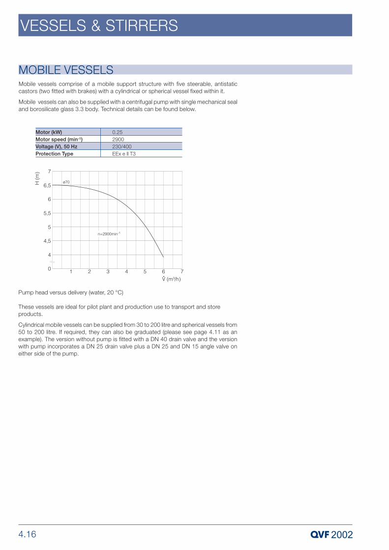
4.16
VESSELS & STIRRERS
MOBILE VESSELSMobile vessels comprise of a mobile support structure with five steerable, antistaticcastors (two fitted with brakes) with a cylindrical or spherical vessel fixed within it.
Mobile vessels can also be supplied with a centrifugal pump with single mechanical sealand borosilicate glass 3.3 body. Technical details can be found below.
Motor (kW)Motor speed (min-1)Voltage (V), 50 HzProtection Type
0.252900230/400EEx e ll T3
These vessels are ideal for pilot plant and production use to transport and storeproducts.
Cylindrical mobile vessels can be supplied from 30 to 200 litre and spherical vessels from50 to 200 litre. If required, they can also be graduated (please see page 4.11 as anexample). The version without pump is fitted with a DN 40 drain valve and the versionwith pump incorporates a DN 25 drain valve plus a DN 25 and DN 15 angle valve oneither side of the pump.
Pump head versus delivery (water, 20 °C)

4.17
VESSELS & STIRRERS
MOBILE VESSELS
MOBILE VESSELSMobile Spherical Vessels
Mobile Cylindrical VesselsReferencewith pump
VGPN30VGPN50VGPN100VGPN150VGPN200
H
15451795194522452545
D
821821962962962
Referencewithout pump
VGFN30VGFN50VGFN100VGFN150VGFN200
DN
300300450450450
DN 1
5050505050
Nominal capacity (l)
3050100150200
Referencewith pump
VFPN50VFPN100VFPN200
H
137014701700
Referencewithout pump
VFN50VFN100VFN200
DN1
200200300
D
9629621245
Nominal capacity (l)
50100200

4.18
VESSELS & STIRRERS
VESSEL COVERS
Covers for Receivers and Spherical Vessels
These components provide the optimum, vacuum-tight closure for vessels Theyfacilitate observation of the process even after fitting or adding dip pipes (please seepages 4.21and 4.22), stirrers (please see pages 4.35 to 4.40), or measuringinstruments(please see section 8 »Measurement & Control«) etc..
Vessel covers with alternative branch sizes and configurations can also be supplied tomeet your special requirements.
If the unit is to be operated under vacuum or at atmospheric pressure, chargebranches can be fitted with a quick release coupling (please see Section 9»Couplings«).
The end form, which depends on the nominal size, is shown in the diagramon page 4.2. Further information can be found in Section 1 »TechnicalInformation«.
These covers are intended for use with spherical and cylindrical vessels used asreceivers. They can, however, also be used with stirrer assemblies.
VESSEL COVERS
ReferenceVZC100/50VZC150/50
VZC200/50VZA200
VZC300/50VZA300/80
VZC450/50VZC600/50VZC800/80VZC1000/80
DN15050
50-
5080
50508080
DN100150
200200
300300
4506008001000
DN22 x 152 x 25
2 x 253 x 40
2 x 253 x 40
2 x 402 x 402 x 802 x 80
L175200
175-
225250
325375550650
d--
-150
-245
----
L179113
126175
161225
221264389488
L2106133
126-
161-
221264389413
TypeAA
BC
BC
BBBB

4.19
VESSELS & STIRRERS
VESSEL COVERSCovers with Central Stirrer BranchThese vessel covers have a centre branch for use in conjunction with a stirrer. Werecommend the incorporation of a baffle to promote turbulence when used withpropeller and turbine stirrers.
ReferenceVZMC300/50VZMC300/80
VZMC450/50VZMC450/80VZMC450/100
VZMC600/50VZMC600/80VZMC600/100
VZMC800/80VZMC800/100VZMC800/150
VZMC1000/80VZMC1000/100VZMC1000/150
DN15080
5080100
5080100
80100150
80100150
DN300
450
600
800
1000
DN28080
150150150
150150150
150150150
150150150
DN4--
505050
505050
---
---
DN33 x 402 x 40
2 x 402 x 402 x 40
2 x 402 x 402 x 40
3 x 803 x 803 x 80
3 x 803 x 803 x 80
d245245
350350350
400400400
450450450
500500500
L1188188
262262262
291291291
386386386
487487487
L250250
325325350
375375400
550550575
650650650
L2188188
259259259
290290290
386386386
412412412
L3225225
285285285
335335335
525525525
600600600
L4--
285285285
335335335
---
---
TypeAB
CCC
CCC
CCC
CCC

4.20
VESSELS & STIRRERS
Covers with Eccentric Stirrer BranchAs the branch provided on these covers for fitting a stirrer is located off-centre, thepossibility of a vortex being set up is avoided to a large extent even when propeller andturbine stirrers are used.
Covers for Reaction VesselsThese covers complement the range described above. They have a centre branch foruse in conjunction with a stirrer, two extra large branches for overhead gear and chargeport plus various other connections.
VESSEL COVERS
VESSEL COVERS
ReferenceVZME200/50VZME300/50
DN15050
DN200300
DN25080
DN3-40
L200250
d-245
L14060
L2139188
L3139188
L4-225
ReferenceVZR450/80VZR600/100
DN180100
DN450600
DN2100100
DN38080
L325400
DN45050
L1175200
L2247288
L3232291
L4285335

4.21
VESSELS & STIRRERS
DIP PIPES
DIP PIPES
The design of the dip pipe depends on the arrangement of the branches on the vesselcover used with spherical or cylindrical vessels.
Straight Dip PipesThese can only be used in conjunction with vertically aligned branches on vessel covers.
Type »DP../100« can be used as a standard dip pipe irrespective of the brancharrangement.
Dip pipes with other lengths can be supplied on request.
ReferenceDP25/100DP40/100DP40/300DP40/500DP40/650DP40/850DP50/100DP50/300DP50/525DP50/650DP50/875
DN12525252525252525252525
DN2540404040405050505050
L1100100300500650850100300525650875
d1828282828282828282828
L100100100100100100100100100100100
TypeABBBBBBBBBB

4.22
VESSELS & STIRRERS
DIP PIPESAngled Dip PipesThis version should be selected for use with branches aligned at 45º for type »VZC..«vessel covers on spherical and cylindrical vessels which are generally used as feedvessels or receivers.
ReferenceDP45/25/115DP45/25/150DP45/40/115DP45/40/165DP45/40/260DP45/40/345DP45/50/150DP45/50/245DP45/50/335DP45/50/435DP45/80/265DP45/80/365DP45/80/525
DN115152525252525252525505050
DN25254040404050505050808080
L100100100100100100100100100100125125125
d13132828282833333333595959
L195115115135150150150150150150200200275
L2115150115165260345150245335435265365525

4.23
VESSELS & STIRRERS
GLASS-LINED REACTION VESSELS
The internal pressure and temperature ratings are -1 to 1 bar g, and -60 to200 °C. The maximum working pressure of a complete reaction unit is dictatedby the pressure rating of the glass components selected for the overheadequipment. The vessels are capable of withstanding full vacuum.
The maximum operating pressure in the jacket is 10 bar g, with a temperaturerange of -60 to 200 °C. Higher pressures are available upon request.
The bottom outlet valve and the attachment bolts for the glass cover areincluded in the scope of supply.
In addition to jacketed glass vessels (see pages 4.8 and 4.13 to 4.15), these glasslinedvessels are also suitable for carrying out reactions with simultaneous heating or cooling.Additionally, due to their unique design, they form the basis for our standard series ofGMP reaction units.
They are supplied as standard with a main body flange of the same diameter as thereactor body, and are thus suitable for the use of both anchor and impeller-typeagitators. The jacket extends all the way up to the main flange, and is equipped withturbulence enhancing nozzles to maximise heat transfer performance. Either steam orthermal oil can therefore be used as the heating medium.
The vessels are designed for use with glass covers (see page 4.10), to permit constantvisual monitoring of the entire reaction process. The glass bottom outlet valve seats ontothe integral block flange at the base of the reactor, with minimum dead volume.
The glass foam insulation (in the VERI.. version) is sheathed in stainless steel, which iswelded top and bottom directly onto the reactor, to totally seal the insulation. The jacketsheath can also be supplied in a polished version on request. Non-insulated reactionvessels are fitted with angle plates to which the support brackets are attached. Forinsulated vessels, the support brackets are welded directly onto the insulation sheathing,thus providing a thermal barrier between the reactor and its supports.
Together with the agitator drives and agitators described on pages 4.35 to 4.45, thesereaction vessels form the basis of our Universal Reaction System. Standard fractionationcolumns, or overheads designed to meet your specific requirements, can also besupplied.
Upon request, we also offer Optimix type reactor vessels made of stainless steel and ofborosilicate glass up to 25 liters. On request, we also supply these reaction vessels inother materials such as stainless steel or hastelloy. If required, the vessel can also befabricated to a very high standard of internal finish, with ground welded seams and/orelectrolytically polished surfaces.

4.24
VESSELS & STIRRERS
GLASS-LINED REACTION VESSELSReaction Vessels
Reference
VER25VERI25VER40VERI40VER63VERI63VER100VERI100
DN2
4040404040404040
D2
380380380380430430580580
D3
615615615615615615755755
D4
-664-664-762-910
d1
1818181818181818
Type
ABABABAB
n x d
16 x 1016 x M816 x 1016 x M816 x 1016 x M820 x M1220 x M12
K
585585585585585585710710
K1
6257406257406808508801000
DN
450450450450450450600600
DN1
2525252525252525
Nominalcapacity (l)
252540406363100100
Reference
VER25VERI25VER40VERI40VER63VERI63VER100VERI100
L2
7373737323233333
L3
9292929292929292
L4
280280280280300300350350
L5
340340340340360360460460
H1
-210-260-380-340
H
718718848848888888848848
E1
320320400400350350350350
L
125125125125125125125125
L1
355355485485575575525525
Nominalcapacit (l)
252540406363100100
Type
ABABABAB
Technical DataReference
VER25, VERI25VER40, VERI40VER63, VERI63VER100, VERI100
Nominalcapacity
(l)254063100
Nominal (m2)0,370,530,750,90
max. (m2)0,520,680,871,04
Heat transfer areaMax.Volume
(l)436080128
stirredVolume
(l)5,75,78,312,6

4.25
VESSELS & STIRRERS
HORIZONTAL SEPARATORS
The end form, which depends on the nominal size, is shown in the diagramon page 4.2. Further information can be found in Section 1 »TechnicalInformation«.
The continuous separation of immiscible liquids with different densities requires low flowrates and the largest possible phase-interface between the light and heavy phase.Horizontal separators satisfy these requirements perfectly.
The separation layer is controlled by means of an adjustable overflow valve that can beinstalled either outside the separator (please see »OF..«, Section 3 »Valves & Filters«) orsealed into it (»AOF..«). The internals of the two types of overflow valve are identical for the same nominal size.
The table below indicates typical figures for maximum possible throughputs in theseseparators. These are based on water at 20º C and are measured without any head inthe input and can only be achieved up to the minimum density difference stated and forbuilt-in overflow valves. We would be pleased to provide an exact layout for you. Non-standard and intermediate sizes (up to DN 1000 and of different lengths), especially forsmaller density differences, can also be supplied upon request.
Minimum difference ∆ρat flow rat
(kg/m3)100100100100100100100
Maximum flow rateheavy phase (H.P.) foroverflow valve
(l/h)4006009001600320050007000
DN
100150200300450600800
Maximum flow rateat low to medium Interfacial tensionΣ heavy (H.P.) and lightphase (L.P.)(l/h)20040080017004000700012000
The borosilicate glass 3.3 coalescer illustrated on page 4.28 is a special feature and itconforms to GMP requirements. It is available in nominal sizes up to DN 300 and canbe incorporated into all horizontal separators and mixer-settlers. It is used to speed upcoalescence which would otherwise be very slow with fine dispersion (please requestspecial leaflet).

4.26
VESSELS & STIRRERS
HORIZONTAL SEPARATORSHorizontal Separators without Overflow ValveTwo supporting brackets for fixing the horizontal separator in the structure are includedwithin the scope of supply. (Please see dimensions in the table below and section 10»Structures & Supports«)
Reference
A100A150A200A300AN450
DN1
254080100150
DN
100150200300450
DN2 (H.P.)DN3 (L.P.)DN4 (vent)
1525405080
L
9501000158021902950
L1
150200200250350
L2
500500100015002000
L3
200200245300355
L4
120140175230330
L5
100100120150175
E1174216218269650
DN100150200300450
E245246896414631400
E3110200200200300
E4165208243295280
d1314141418
Dimensions

4.27
VESSELS & STIRRERS
HORIZONTAL SEPARATORSHorizontal Separators with Built-In Overflow ValveTwo supporting brackets for fixing the horizontal separator in the structure are includedwithin the scope of supply. (Please see dimensions in the table below and section 10»Structures & Supports«).
Reference
AOF100/15AOF150/25AOF200/40AOF300/50AOF450/80AOF600/100AOF800/100
DN1
254080100150150150
DN
100150200300450600800
DN2 (H.P.)DN3 (L.P.)DN4 (vent)
1525405080100100
DN5
15252540404040
L
950110016802310307527503140
L1
150200200250350425575
L2
50050010001500200015001500
L3
220300345405475575600
L4
110140175230330420535
L5
70100120150175225225
L6
70100100120150175175
L7
110140175230305380495
H
252274349386500640775
E1174216218269650725925
DN100150200300450600800
E245246896414631400900800
E3110200200200300400630
E4165208243295280362475
d13141414141414
Dimensions

4.28
VESSELS & STIRRERS
HORIZONTAL SEPARATORSCoalescersSpecial features of these items are resistance to fouling, their ability to break down foamand their high efficiency with a limiting drop size of Ž 20 µm and a maximum flow volume,based on the empty pipe, of 25 m3/m2 h (please see pages 4.26 and 4.27).
L
360360540540
DN
100150200300
L1
100100150150
L2
50050010001000
Number ofelements
4466
Capacity (l/h)
2004008001700
If the number of individual elements required differs from the figure shown inthe table below, please specify the number required when ordering.
Reference
COSA100COSA150COSA200COSA300

4.29
VESSELS & STIRRERS
MIXER-SETTLERSMixer-settlers are used for extraction processes wherever there are great demands inflexibility on the operation of the plant. Frequently changing products, alterations to thenumber of stages required or wide variations in throughput can be decisive factors inthis decision process. A precondition for their use is, however, that only a restrictednumber of theoretical stages is required.
Scaling-up presents no problem since back-mixing effects can be excluded completelyby the clear separation of the light and heavy phases in each stage. When properly sized,each practical stage also corresponds approximately to a theoretical stage.
Each mixer-settler stage consists of a mixing chamber with a self-priming, variable speedstirrer as shown in the diagram below and a horizontal separator without a reducer onthe inlet end (please see »AOF..«, page 4.27), i.e. the two phases are mixed in each stagethen allowed to settle and separate from each other. The assemblies indicated, i.e. mixerand settler zone, are physically separated by a weir fitted within the flange coupling.
By connecting several mixer-settler stages in series and arranging for the phases to flowcountercurrent to each other, the plant can be adapted to handle the particularseparation problem in hand.

4.30
VESSELS & STIRRERS
CYCLONESThe cyclones described here are designed for the separation not only of droplets fromgases and vapours but also of particulate solids from gases. The overall degree ofseparation can be as high as 99%, but this figure is governed to a very large extent bythe following parameters:
- Liquid loading of the gas or vapour or the solids loading of the gas
- Droplet or particle size range
- Droplet or particle size distribution
For the standard air/water system at ambient temperature and with a gas velocity of 15 m/s in the dip tube, limiting droplet diameters are approx. 2.5 µm for the DN 100 andDN 150 nominal sizes and approx. 3.5 µm for nominal sizes DN 200 and DN 300. Thepressure drop in these cases is in the region of 25 to 30 mbar.
We would be pleased to provide an exact design for the cyclone you require.
ReferenceCY100CY150CY200CY300
DN225252525
DN1405080100
DN380100150150
L4125150200275
L71483911191425
L15606559151225
L2180235320405
L3284349429485
L5355575100
DN100150200300

4.31
VESSELS & STIRRERS
HEATING MANTLES FOR SPHERICAL VESSELS
Nominal capacityof spherical vessel (l)
102050100200
ReferenceTyp BHHK10HHK20HHK50HHK100HHK200
D
280350490610750
D1
370440580700840
d2
313388555676821
d3
120120120120140
d4
4 x M124 x M124 x M124 x M124 x M12
L
1015202020
H
185230300380445
DN
4040404050
As an alternative to heating baths (please see pages 4.32 and 4.33) electric heatingmantles can also be supplied for spherical vessels. Their heating power varies accordingto the nominal capacity of the vessel involved.
These heating mantles are subdivided into several heating zones each of which isequipped with a temperature probe so that the surface temperature of the vessel canbe monitored. These work in conjunction with the control unit included in the supply toprevent local hot spots occurring. The control unit also includes energy regulators whichcan be used to control the heat input separately for each heating zone depending onthe liquid level.
For the heating mantle type HHW (version A), product temperature control is possiblevia an additional resistance thermometer (see Chapter 8 »Measurement/ControlDevices«). If no product temperature control is needed, or if such is performed by useof an existing contact thermometer, the heating mantle may also be delivered with asimple control device (type HHK, version B).
The number of heating zones and supply voltage of the heating mantles are indicatedin the table below.
If the heating mantle is to be used for a spherical vessel without abottom outlet or with a non-standard bottom outlet, the cataloguereference becomes »HH(W/K).., but for spherical vessel without bottomoutlet« or »HH(W/K).., but for DN .. bottom outlet« respectively. Themaximum nominal size for the outlet is DN100.
In view of the heat involved, a metal coupling must be used on thevessel’s bottom outlet (please see Section 9 »Couplings«).
Nominal capacityof spherical vessel (l)102050100200
power(kW)1,62,44,56,09,0
Voltage(V), 50 Hz 230230230/400, 3ph230/400, 3ph230/400, 3ph
Number of heating zones33345
Heating mantles are fixed in the support structure using »KK50-..« or »KKO50-..«structure fittings or »RRM..« type support mount (see Section 10 »Structures &Supports«). The weight of the spherical vessels and other components used inconjunction with them must be supported on separate fixed points.
Heating mantles can also be supplied for cylindrical vessels on request.
ReferenceTyp AHHW10HHW20HHW50HHW100HHW200

4.32
VESSELS & STIRRERS
HEATING BATHS FOR SPHERICAL VESSELSHeating baths can be used to advantage in applications where the materials beinghandled would tend to block or stick to the coils of immersion heat exchangers or wherethe use of heating mantles is not recommended. Options are available for heating eitherelectrically or with steam.
The spherical vessel sits on a support ring and a restraint prevents it from floating up. Astuffing box seals the bottom outlet to prevent leakage from the bath. The design alsoavoids imposing any stresses on the spherical vessel.
The baths are made of steel. The external surface is primed and painted.
The heat transfer fluid in the bath can be, for example, water of boiler feed water qualityor a synthetic oil. The bath temperature must always be a sufficient amount below theboiling temperature of the fluid. To ensure that this condition is met, the heating bathscan be fitted with suitable temperature control equipment if required.
Complete stainless steel heating baths and heating baths for cylindrical vessels can besupplied to special order.
Where it is necessary to ensure that the liquid in the bottom outlet is heated itis recommended to use spherical vessels with »BAL40« bottom outlet valve(please see Section 3 »Valves & Filters«).
HEATING BATHS FOR SPHERICAL VESSELSHeating Baths, Steam HeatedThe »BHKD..BAL« version is suitable for spherical vessels with sealed in seat for a»BAL40« bottom outlet valve, the »BHKD..E« version for spherical vessels with extendedbottom outlet (please see page 4.5).
The maximum permissible steam pressure in the heating coils is 10 bar g.
If required, a steam control valve, flexible hose and condensate separator can besupplied with these heating baths.
Nominal capacity ofspherical vessel (l)
2050100200
Referencewith VS...E
BHKD20EBHKD50EBHKD100EBHKD200E
Referencewith VS...BAL
BHKD20BALBHKD50BALBHKD100BALBHKD200BAL
D
490625730910
d1
295395585585
d2
3 x 203 x 203 x 203 x 20
L
255305365450
L1
215280290400
L2
310380440530
L3
65858590
H
270340390480
DN
15152525

4.33
VESSELS & STIRRERS
HEATING BATHS FOR SPHERICAL VESSELSHeating Baths, Electrically HeatedAs a standard these baths are supplied with either non hazardous or hazardous areaimmersion heating elements. As a consequence of the lower permissible surfacetemperature of the latter their heat output is lower. The supply voltage is 230/400 V, 3ph, 50 Hz in both cases.
Heating baths with hazardous area immersion heating elements are fitted with a levelcontrol.
The »BHKE..BAL« and »BHKX..BAL« versions are suitable for spherical vessels withsealed in seat for a »BAL40« bottom outlet valve, the »BHKE..E« and »BHKX..E«versionsfor spherical vessels with extended bottom outlet (please see page 4.5).
D
490625730910
d1
295395585585
d2
3 x 203 x 203 x 203 x 20
L
400470520610
L1
183250305395
H
270340390480
Power(kW)3,66,09,011,0
Non hazardous area immersion heating elements Nominal capacity ofspherical vessel (l)
2050100200
Referencewith VS...E
BHKE20EBHKE50EBHKE100EBHKE200E
Referencewith VS...BAL
BHKE20BALBHKE50BALBHKE100BALBHKE200BAL
D
490625730910
d1
295395585585
d2
3 x 203 x 203 x 203 x 20
L
530600650740
L1
170237290380
H
270340390480
H1
155155155155
H2
435505555645
Power(kW)3,86,09,011,4
EEx de IIC T3 protection type immersion heating elements Nominal capacity ofspherical vessel (l)
2050100200
Referencewith VS...E
BHKX20EBHKX50EBHKX100EBHKX200E
Referencewith VS...BAL
BHKX20BALBHKX50BALBHKX100BALBHKX200BAL

4.34
VESSELS & STIRRERS

4.35
VESSELS & STIRRERS
STIRRER DRIVESWe can supply a range of drive assemblies for mixing, homogenising etc. using corrosionresistant stirrers (please see pages 4.43 to 4.45). They comprise various types of driveunit and stirrers of the appropriate shaft diameter in PTFE-sheathed or glass coated steeland borosilicate glass 3.3 (or stainless steel on request). The actual stirrer selecteddepends on the intended duty.
A selection of possible combinations of vessel, covers or adaptor flanges, stirrers anddrives can be found in the tables below. The selection of a suitable combination of stirrerand drive power relates to materials of low to medium viscosities.
Stirrer Drives for Glass Vessels
Nom. cap. (l)10
20
50
Stirrer DriveRAK50/034 or FAK50/037
RAK50/034 or FAK50/037
RAK50/034 or FAK50/037
StirrerSPG90/620
SPG90/700
SPG140/820
Vessel and ReducerVSM10 and PR100/50
VSM20 and PR100/50
VSM50 and PR200/50
Spherical Vessel with Reducer
Nom. cap. (l)10
20
30
50
50
100
150
Stirrer DriveRAK50/034 or FAK50/037
RAK50/034 or FAK50/037
RAK50/034 or FAK50/037
RAK50/034 or FAK50/037
RAL80/035 or FAL80/035
RAL80/055 or FAL80/055RAL100/075 or FAL100/075
RAL100/075 or FAL100/075
StirrerSPG90/700
SPG140/700
SPG140/820
SPG140/1000
STT140/1080 or SPT 145/1070
STT140/1080 or SPT145/1070STT140/1080 or SPT145/1070
STT140/1380 or SPT190/1370
Vessel and CoverVZ10/200 and VZC200/50
VZ20/300 and VZME300/50VZ20/300 and VZC300/50VZ20/300 and VZMC300/50
VZ30/300 and VZME300/50VZ30/300 and VZC300/50VZ30/300 and VZMC300/50
VZ50/300 and VZME300/50VZ50/300 and VZC300/50VZ50/300 and VZMC300/50
VZ50/300 and VZA300/80VZ50/300 and VZC300/80VZ50/300 and VZMC300/80
VZN100/450 and VZMC450/80VZN100/450 and VZMC450/100
VZN150/450 and VZMC450/100
Cylindrical Vessel with Cover
Nom. cap. (l)50
100
100
Stirrer DriveRAL80/035 or FAL80/035
RAL80/055 or FAL80/055
RAL100/075 or FAL100/075
StirrerSTT140/700 or SPT145/690
STT140/800 or SPT145/790
STT140/800 or SPT145/790
Vessel and PlateVSM50 and TFR200/80
VSM100 and TFR200/80
VSM100 and TFR200/100
Spherical Vessel with Cover Plate

4.36
VESSELS & STIRRERS
STIRRER DRIVES
In addition to the electrically operated drives shown, we are also able tosupply pneumatically operated stirrer drives on request.
The stirrer drives except types »RAK..« and »FAK..« are fitted with anti-vibrationmountings to avoid transmission of vibration from the motor to the structureand from there to the glass plant. They are fitted to the bearing housing (up toa power rating of 0.75 kW) or between the stirrer drive and the base plate.
The gasket, backing flange and fixings are included in the supply.
Stirrer Drives for Glass-Lined Reaction VesselsNom. cap. (l)25
40
63
100
25
40
63
100
Stirrer DriveRAL80/055 or FAL80/055
RAL80/055 or FAL80/055
RAL80/055 or FAL80/055
RAL100/075 or FAL100/075
RALA80/075 or FALA80/075
RALA80/075 or FALA80/075
RALA80/075 or FALA80/075
RALA100/110 or FALA100/110
StirrerSIE230/820
SIE230/950
SIE230/985
SIE230/1020
SAE335/820
SAE335/950
SAE385/985
SAE500/1020
Reaction VesselVER25 or VERI25
VER40 or VERI40
VER63 or VERI63
VER100 or VERI100
VER25 or VERI25
VER40 or VERI40
VER63 or VERI63
VER100 or VERI100

4.37
VESSELS & STIRRERS
STIRRER DRIVESVariable Speed Drive Assemblies with Bearing AssemblyThese assemblies incorporate a flange-mounted bearing assembly. This is fitted belowa variable speed drive motor and facilitates direct mounting of the complete drive unitonto a glass vessel cover. The drive spindle and stirrer shaft are connected inside thehousing by means of a clamp type coupling for smaller drives or muff type for largerdrives.
In order to meet the stirring duty, the speed can be varied from 0 up to the respectivemaximum via a manual hand wheel for these drive types. The setting can be changedwith the drive stopped or in operation. Before switching on the drive motor it should beset to its lowest speed.
As standard, electric motors are manufactured to protection type EEx e II T4 and EExde IIC T4, and for voltage connections of 230/400V, 3 phase, 50 Hz.
To facilitate supporting the drive unit in the structure, structure fittings and tubularstructures can be used (please see Section10 »Structures & Supports«). They are not included in the supply.
These stirrer drive units are designed for use with PTFE, glass coated steel and stainlesssteel stirrers with a shaft diameter of 44.5 mm.
ATEX Version with Single-Acting Mechanical SealProtection Type II 1/2 G c b II T4
The stirrers (suffix ..SAT) with single-acting mechanical seals are approved for operationswithin zone 0 (category 1) inside the vessel, and for zone 1 (category 2) outside thevessel in accordance with EU directive 94/9/EG (ATEX).
The mechanical seals operate on a SIC/hard-carbon sealing surface, and conform toFDA requirements. An integrated-temperature measuring device built into the sealingplate, which is a requirement for regulation-conform operations, monitors the maximumtemperature within the mechanical seal. For use within the temperature class T4, thetemperature rating is 100°C, for T3 it is 150°C.
ATEX Version with Double Mechanical Seal Protection Type II 1/2 G c b II T4
The stirrers (suffix ..AT) with double acting fluid-lubricant mechanical seals are approvedfor operations within zone 0 (category 1) inside the vessel, and for zone 1 (category 2)outside the vessel in accordance with EU directive 94/9/EG (ATEX).
The mechanical seal operates on a PTFE/ceramic sealing surface.
The installation of a cooled lubricant circulation is required to conform to regulations andfor which the sealing liquid level within the vessel and the sealing media temperature(as measured within the mechanical seal casing) shall be monitored, contingent to theabove rating.
Temperature monitoring may be omitted if the stirrer is only deployed within zone 1(category 2) inside the vessel.
If the maximum sealing media temperature is held at 50°C, use is possible at producttemperatures ranging up to 200°C.If used at temperature class T4, the maximum producttemperature shall not exceed 108°C; for T3, it shall not exceed 160°C.
The length L of the stirrer is extended by 90 mm compared to the single-actionmechanical seal, along with the overall length for the drive.
Version with Single-Action, non ATEX Mechanical SealThe stirrer version with single-action mechanical seal that does not conforming to ATEXoperates on PTFE/ceramic sealing surface, which has proven itself in many years of use.
The operating temperature is limited to 120°C.

4.38
VESSELS & STIRRERS
DRIVES WITH VARIABLE SPEEDMotor protection type EEx e II T4
ReferenceRAL80/035RAL80/055RAL100/075
RALA80/075RALA100/110
d44,544,544,5
44,544,5
DN8080100
80100
d12 x M102 x M102 x M10
2 x M102 x M10
D2138156156
156176
H730800800
945990
H1138138138
138138
H2153153153
153153
H3298298298
298298
Power (kW)0,500,550,65
0,651,35
Speed (min-1)0-8000-6000-600
0-2400-240
ReferenceFAL80/035FAL80/055FAL100/075
FALA80/075FALA100/110
d44,544,544,5
44,544,5
DN8080100
80100
d12 x M102 x M102 x M10
2 x M102 x M10
D2138156156
156176
H770840840
9901005
H1138138138
138138
H2153153153
153153
H3298298298
298298
Power (kW)0,550,550,75
0,751,50
Speed (min-1)0-8000-6000-600
0-2400-240
Protection type EEx de IIC T4
ATEX VERSION WITH DRY RUNNING MECHANICAL SEALProtection Type II 1/2 G cb II T4
ReferenceRAL80/035/SATRAL80/055/SATRAL100/075/SAT
RALA80/075/SATRALA100/110/SAT
d44,544,544,5
44,544,5
DN8080100
80100
d12 x M102 x M102 x M10
2 x M102 x M10
D2138156156
156176
H730800800
945990
H1138138138
138138
H2153153153
153153
H3298298298
298298
Power (kW)0,500,550,65
0,651,35
Speed (min-1)0-8000-6000-600
0-2400-240
ReferenceFAL80/035/SATFAL80/055/SATFAL100/075/SAT
FALA80/075/SATFALA100/110/SAT
d44,544,544,5
44,544,5
DN8080100
80100
d12 x M102 x M102 x M10
2 x M102 x M10
D2138156156
156176
H770840840
9901005
H1138138138
138138
H2153153153
153153
H3298298298
298298
Power (kW)0,550,550,75
0,751,50
Speed (min-1)0-8000-6000-600
0-2400-240
Protection Type II 1/2 G cb II T4

4.39
VESSELS & STIRRERS
ATEX VERSION WITH DOUBLE ACTING MECHANICAL SEAL
Protection type II 1/2 G cb II T4
d
44,544,544,5
44,544,5
DN
8080100
80100
Reference
RAL80/035/ATRAL80/055/ATRAL100/075/AT
RALA80/075/ATRALA100/110/AT
d1
2 x M102 x M102 x M10
2 x M102 x M10
D2
138156156
156176
H1
234234227
234227
H2
153153153
153153
H
816886886
10341078
H3
393393386
393386
Power(kW)0,500,550,65
0,651,3
Speed(min -1)0-8000-6000-600
0-2400-240
Protection type II 1/ 2 G cb II T4
d
44,544,544,5
44,544,5
DN
8080100
80100
Reference
FAL80/035/ATFAL80/055/ATFAL100/075/AT
FALA80/075/ATFALA100/110/AT
d1
2 x M102 x M102 x M10
2 x M102 x M10
D2
138156156
156176
H1
234234227
234227
H2
153153153
153153
H
862933926
10811114
H3
393393386
393386
Power(kW)0,550,550,75
0,751,5
Speed(min -1)0-8000-6000-600
0-2400-240

4.40
VESSELS & STIRRERS
DRIVES WITH FREQUENCY CONVERTERS
Drives for Frequency InverterThis type of drive can be used whenever variations in speed are achieved by means ofa frequency inverter. The flameproof electric motor is fitted with the required thermistorsas standard. These drives can also be used to drive stirrers at a fixed speed (750 rpm),this can however cause problems on start-up. Such a solution should, therefore, onlybe adopted in exceptional cases.
The drive shaft and stirrer blade are also connected to each other via a clamp couplingwithin the lantern, just as the variants with gear motor.
The electric motors, which have a minimum speed of 75 rpm, are supplied withprotection type EEx de llC T4 and for a 230/400 V, 3 phase, 50 Hz supply. It shall beobserved that the small torque available at low turning speed can lead to difficulties fortough media or tasks.
These stirrer drive units are designed for use with PTFE, enamelled steel and stainlesssteel (on request only) stirrers with a 44.5 mm shaft diameter.
ATEX Version with Single-Acting Mechanical SealProtection Type II 1/2 G c b II T4
The stirrers (suffix ..SAT) with a single-acting mechanical seal are approved for use inzone 0 (category 1) inside the vessel, and zone 1 (category 2) outside the vessel inaccordance with EU directive 94/9/EG (ATEX).
The mechanical seal operates on a SIC/hard-carbon sealing surface, and is conform toFDA requirements. The maximum temperature within the mechanical seal is monitoredby an integrated temperature measurement device within the sealing plate, which is arequirement for regulation-conforming operations.
The temperature rating is 100°C for use in temperature class T4; for T3 it is 150°C.
ATEX Version with Double Mechanical SealProtection Type II 1/2 G c b II T4
The stirrers (suffix ..AT) with a double acting mechanical seal are approved for use inzone 0 (category 1) inside the vessel, and zone 1 (category 2) outside the vessel inaccordance with EU directive 94/9/EG (ATEX).
The mechanical seal operates on a PTFE/ceramic sealing surface.
The installation of a cooled lubricant circulation is required to conform to regulations andfor which the sealing liquid level within the vessel and the sealing media temperature(as measured within the mechanical seal casing) shall be monitored, contingent to theabove rating.
Temperature monitoring may be omitted if the stirrer is only deployed within zone 1(category 2) inside the vessel.
If the maximum sealing media temperature is held at 50°C, use is possible at producttemperatures ranging up to 200°C.If used at temperature class T4, the maximum producttemperature shall not exceed 108°C; for T3, it shall not exceed 160°C.
The length of the stem is extended by 90 mm compared to the single-action mechanicalseal, along with the overall length for the drive.
Version with Single-Action, non ATEX Mechanical SealThe stirrer version with single-action mechanical seal that does not conforming to ATEXoperates on PTFE/ceramic sealing surface, which has proven itself in many years of use.
The operating temperature is limited to 120°C.

4.41
VESSELS & STIRRERS
DRIVES FOR FREQUENCY CONVERTERS
Motor protection type .EEx e II T4
Reference
RAE80/037RAE80/055RAE80/075
RAE100/037RAE100/055RAE100/075RAE100/110
d
44,544,544,5
44,544,544,544,5
DN
808080
100100100100
d1
2 x M102 x M102 x M10
2 x M102 x M102 x M102 x M10
D2
188188206
188188206206
H
680680725
673673725725
H1
138138138
138138138138
H2
153153153
153153153153
H3
298298298
298298298298
Power(kW)0,370,550,75
0,370,550,751,10
Speed with Freq. Inverter (min-1)75-75075-75075-750
75-75075-75075-75075-750
Protection type .II 1/2 G cb II T4
ATEX Version with Dry Running Mechanical Seal
Reference
RAE80/037/SATRAE80/055/SATRAE80/075/SAT
RAE100/037/SATRAE100/055/SATRAE100/075/SATRAE100/110/SAT
d
44,544,544,5
44,544,544,544,5
DN
808080
100100100100
d1
2 x M102 x M102 x M10
2 x M102 x M102 x M102 x M10
D2
188188206
188188206206
H
680680725
680680725725
H1
138138138
138138138138
H2
153153153
153153153153
H3
298298298
298298298298
Power(kW)0,370,550,75
0,370,550,751,10
Speed with Freq. Inverter (min-1)75-75075-75075-750
75-75075-75075-75075-750
ATEX Version with Double Acting Mechanical Seal
Protection type .II 1/2 G cb II T4
d
44,544,544,5
44,544,544,544,5
DN
808080
100100100100
Reference
RAE80/037/ATRAE80/055/ATRAE80/075/AT
RAE100/037/ATRAE100/055/ATRAE100/075/ATRAE100/110/AT
d1
2 x M102 x M102 x M10
2 x M102 x M102 x M102 x M10
D2
188188206
188188206206
H1
230230230
230230230230
H2
153153153
153153153153
H
770770815
770770815815
H3
388388388
388388388388
Power(kW)0,370,550,75
0,370,550,751,10
Speed with Freq. Inverter (min-1)75-75075-75075-750
75-75075-75075-75075-750

4.42
VESSELS & STIRRERS
STIRRER DRIVES FOR GLASS STIRRERSCompact Variable Speed DrivesThese assemblies incorporate a variable speed drive motor and a closed housingsuitable for mounting directly onto a vessel cover. The motor spindle and stirrer shaftare connected together with grub screws. The single acting mechanical seal is locatedin the housing. These are both easily accessible after removing the drive motor. Anopening is provided on the housing so that the rotating part of the mechanical seal canbe locked in position on the stirrer shaft.
On vessel covers, compact drives suitable for coupling to a DN 50 nominal size branchare used.
These Stirrer Drive units are designed for use with borosilicate glass 3.3 stirrerswith a 32 mm shaft diameter and a maximum length of 1000 mm (please seepage 4.45). Their use is therefore restricted to a maximum stirred volume of 50litres.
Electric motors are supplied as standard in protection type EEx e ll T4 or EEx de llC T4and for a 230/400 V, 3 phase, 50 Hz supply. Other voltages and frequenciescan also be catered for. The stirrer drive is not certified in accordance with ATEX.
The maximum allowable operating temperature for the single acting mechanicalseal is 120 ºC.
Reference
RAK50/034
d
32
DN
50
D1
145
D2
145
H
517
H1
119
Power(kW)
0,34
Speed(min-1)
0-550
Protection type EEx e II T4
Reference
FAK50/037
d
32
DN
50
D1
145
D2
150
H
543
H1
119
Power(kW)
0,37
Speed(min-1)
0-550
Protection type EEx de IIC T4

4.43
VESSELS & STIRRERS
THERMOSIPHON UNITSThese units work on the thermosiphon principle. We always recommend using them inconjunction with double mechanical seals whenever handling substances that are toxicor highly corrosive, that contain abrasive components or that have a tendency tocrystallise. The barrier fluid, which should be chosen on the basis of its compatibility withthe product, carries out three functions necessary for trouble-free operation: it acts asa barrier, provides lubrication and keeps the unit cool. It is covered by a gas buffer,pressurised to suit the operating pressure in the reaction vessel.
Thermosiphon units are supplied with or without a top-up unit to maintain the barrierfluid level during operation. This cannot be retrofitted.
Type »THAO..« (without top-up unit) comprises a vessel with an internally fitted coolingcoil in stainless steel, pressure gauge and sight glass together with the fittings necessaryfor connection to the mechanical seal including 4 m stainless-steel clad hose. Type»THAP..« (with top-up unit) comprises the same items plus an additional vessel and abuilt-on hand-pump. The parts in contact with the product are also made of stainless steel.
Technical dataTHAO3THAO/AT32,5
0,1
THAO6THAO6/AT64
0,14
THAP3THAP3/AT32,5
0,1
THAP6THAP6/AT64
0,14
Tank Capacity(l)3636
ReferencewithoutATEXTHAO3THAO6THAP3THAP6
D
140170140170
d1
M10M10M10M10
B
--230260
H
475550475550
E
9511095110
E1
292292292292
E2
60606060
Type
ABAB
Reference
Tank CapacityNominal CapacityHeat Transfer Area of the Cooling Coil
ll
m2
If stirrer drives are used with siphon systems in areas with danger of explosionwithin the European Union ATEX, the siphon vessel must be monitored for aminimum fill level using a fill-level probe in accordance with EU directive 94/9/EC(ATEX). If you select the order number ending AT, then you will receive the siphonvessel with an integrated fill-level probe.
ReferencewithATEXTHAO3/ATTHAO6/ATTHAP3/ATTHAP6/AT

4.44
VESSELS & STIRRERS
CONNECTING FLANGES FOR STIRRERSWhere space is limited or, if for other reasons, there is no need to fit a vessel cover(please see pages 4.18 to 4.20) with its various branches, the stirrer drives describedabove, with the exception of types »RAK..« and »FAK..«, can also be mounted directlyonto spherical vessels (please see pages 4.5 to 4.8) by means of these connectingflanges. They are stainless steel rings which are PTFE-sheathed in the area in contactwith the product and are available as standard for DN 200 and DN 300 branches. Noadditional gaskets are required.
ReferenceTFR200/80TFR200/100TFR300/80TFR300/100
DN18010080100
DN200200300300
D321321428428
D17610476104
L19191919
The adaptor flange, insert and fixings are included in the supply.
The PTFE used in the manufacture of these stirrers is carbon filled.
Conductive material may be delivered upon request.
For construction reasons the maximum possible stirrer length is limited to 1800 mm.
PTFE STIRRERSThe different shapes of vessel (spherical or cylindrical vessels) on the one hand and theduties to be carried out on the other (suspension, homogenisation, with or withoutsimultaneous heat transfer etc.) determine the type of stirrer to be used. Their design(propeller or turbine) is another factor influencing the need or otherwise for a baffle tocreate turbulence. Further information can be found with the individual types of stirrer.
These two-piece stirrers consist of a PTFE-sheathed shaft and a PTFE stirrer elementwith steel core that is attached to the shaft to prevent twisting. A perfect seal ismaintained between the two parts over the whole permissible temperature range (-50 to +150 ºC).

4.45
VESSELS & STIRRERS
PTFE STIRRERSPropeller StirrersThese stirrers produce axial primary flow with a radial component and are particularlysuitable for homogenisation and suspension. They are also suitable for general stirringduties with simultaneous heat transfer (heating or cooling) between the liquid beingstirred and the vessel wall. They can also be used for dispersion (including from gases)and emulsification.
Propeller stirrers are mainly used with borosilicate glass 3.3 spherical and cylindricalvessels. In the latter case it is recommended that they be installed on an eccentric stirrerbranch to avoid setting up a vortex.
ReferenceSPT145/690SPT145/790SPT145/1070SPT190/1370
D145145145190
L69079010701370
d144,544,544,544,5
ReferenceSTT140/700STT140/800STT140/1080STT140/1380
D140140140140
L70080010801380
d144,544,544,544,5
PTFE STIRRERSTurbine StirrersThese stirrers produce a radial primary flow and are recommended for homogenisation,dispersion (including from gases) and emulsification. They can also be used when heattransfer between the liquid being stirred and the vessel wall is required.
Turbine stirrers are mainly used with borosilicate glass 3.3 spherical vessels andcylindrical vessels. In the latter case it is recommended that they be installed on aneccentric stirrer branch to avoid setting up a vortex.

4.46
VESSELS & STIRRERS
GLASS COATED STEEL STIRRERSWe supply one-piece impeller and anchor type glass coated steel stirrers with a 44.5mm shaft diameter for use with the glass lined steel reaction vessels described on pages4.23 and 4.24.
ReferenceSIE230/820SIE230/950SIE230/985SIE230/1020
D230230230230
L8209509851020
d144.544.544.544.5
ReferenceSAE335/820SAE335/950SAE385/985SAE500/1020
D335335385500
L8209509851020
d144,544,544,544,5
GLASS COATED STEEL STIRRERSAnchor StirrersThese are used for applications involving relatively low speeds at the circumference andwhere higher viscosities may be encountered. They are particularly suitable forhomogenisation with simultaneous heat transfer between the liquid being stirred and thevessel wall. Anchor stirrers are used with types »RALA..« and »FALA..« stirrer drive units(please see page 4.38).
When these stirrers are used the drive power required needs to be assessed.We would be happy to do this for you.
Impeller StirrersThese stirrers generate a radial primary flow and are used mainly for homogenising highviscosity liquids. They are also ideally suited for applications where good heat transferis required between the liquid being stirred and the vessel wall. Impeller stirrers are usedwith types »RAL..«, »FAL..« and »RAE..« stirrer drive units (please see pages 4.38 and 4.39).

4.47
VESSELS & STIRRERS
GLASS STIRRERSIt is possible to produce propeller and vortex type stirrers in borosilicate glass 3.3 withits almost universal resistance to corrosion.
All glass stirrers have a 32 mm shaft diameter and can be used with the »RAK..« and»FAK..« type stirrer drives (as described on page 4.42).
ReferenceSPG90/620SPG90/700SPG140/700SPG140/820SPG140/1000
D9090140140140
L6207007008201000
d13232323232
GLASS STIRRERSPropeller StirrersAs a result of the axial primary flow these stirrers produce, there is a very wide range ofapplications for them. They are used for homogenisation, dispersion (also from gases)and emulsification and they can also be used on a restricted basis for suspensions.Another application for them is for stirring with simultaneous heat transfer (heating orcooling) between the liquid being stirred and the vessel wall.

5 HEAT EXCHANGER
PROCESS PLANT COMPONENTS
P 305 e.3 Copyright © 2007, QVF Engineering GmbH. All rights reserved.

5.2
HEAT EXCHANGER
IntroductionQVF heat exchangers provide the optimum solution for every requirement encounteredin practice because of the wide range of types available. This applies not only to coiltype heat exchangers, which are available as condensers, boilers and immersion heatexchangers, but also to shell and tube heat exchangers, which are designed for use withtubes in the widest possible range of corrosion resistant materials.
These items are widely used in the chemical, pharmaceutical and allied industriestogether with other applications such as food and drink production, dye works andelectroplating. This is because of the special properties of borosilicate glass 3.3 and allthe other materials used plus the fact that borosilicate glass 3.3 is an approved andproven material of construction for pressure vessels.
Reference should also be made in this context to the extreme reliability of the strongand high-duty coupling system used for all components. This is achieved throughoutthe whole range of nominal sizes by the use of the safety buttress end which has beendesigned specifically by taking into account the properties of the material coupled witha reliable flange system.
The complete range of standard heat exchanger components is described on thefollowing pages. Non-standard components that can be supplied to special order arereferred to in the respective product description.
A detailed listing of all heat exchangers by »Description« and »Catalogue Reference« canbe found in the »Index«.
Detailed information on a number of the topics referred to in the followingpages can be found in Section 1 »Technical Information«.
Details of the design of the different types of optimised buttress ends areillustrated alongside.
GMP compliant installationsThe use of heat exchangers and the layout of interconnecting pipeline incorporatingvalves when designing plant and equipment complying with GMP regulations, calls forspecial care in both the planning and selection of the components used together withthe materials of construction used for them. Borosilicate glass 3.3 has a number ofspecial properties that are highly valued in the pharmaceutical industry and these inconjunction with materials approved in accordance with the FDA catalogue, such asPTFE (bellows, lining, coating), glass-lined steel (heat exchanger shells) and specialmaterials (silicon carbide etc.) ensure that any build-up of unwanted deposits is avoidedin areas which come in contact with the product. A design without any dead space,which ensures that components drain fully and can be cleaned easily and effectively, isachieved by the shape of the components (e.g. coil and circular ring type heatexchangers) and the way they are installed. Where the external surfaces of thesecomponents have to comply with clean room requirements, appropriate stainless steelcoupling and support material can be supplied (please see Section 9 »Couplings« andSection 10 »Structures and Supports«).
We would be happy to advise you on the basis of the regulatory requirements applicableto a particular case and the guidelines drawn up by us for the design of GMP compliantplant.
DN15 - DN150
DN200 - DN300
DN450 - DN1000

5.3
HEAT EXCHANGER
Glass components suitable for higher permissible operating conditions canalso be supplied on request.
Coated heat exchangersDamage to borosilicate glass 3.3 assemblies resulting from accidental external causescannot be entirely excluded, especially in the smaller nominal sizes. This is primarily dueto the relatively rigorous conditions prevalent in production plants and applies especiallywhere no additional protection is provided in the form of insulation.
Our answer to this problem is to provide borosilicate glass 3.3 heat exchangers with aSectrans transparent coating. This can be applied irrespective of the shape of thecomponent and it provides additional protection without having any adverse effect onvisual monitoring of the process.
A glass fibre reinforced polyester coating providing a higher level of protection can alsobe supplied on request. This does have a slightly adverse effect on the transparency ofthe glass, making it translucent and not transparent.
Permissible operating conditionsWhile the maximum permissible operating temperature for borosilicate glass 3.3 heatexchanger bodies is generally 200 ºC (∆Θ ≤ 180 K), the maximum permissible operatingpressure is governed by the main nominal size of the component but not by its shape.Detailed information on this can be found in Section 1 »Technical Informaton«.
The maximum permissible figures for pressure and temperature gradient across the heatexchange surfaces and PTFE tube plates (between the media) and the permissibleoperating conditions for components in other materials can be found in the respectiveproduct description.

5.4
HEAT EXCHANGER
Unlike the shell and tube heat exchangers described on pages 5.15 to 5.22 theseitems have the coil battery welded to the jacket. This is of importance for plant whichhas to conform to GMP requirements since it ensures that the product and thecoolant cannot come into contact with each other.
Coil type heat exchangers are mainly used as condensers or coolers. They can,however, be used for heat transfer between liquids and gases in general. Turbulent flowis ensured even in the larger nominal bores since the coil layers are offset and fill the flowcross-section to a great extent.
Information on pressure drop in the coils together with performance data which can beused to estimate the heat transfer surface required can be found on pages 5.6 and 5.7.We would be happy to carry out detailed design work for you.
The permissible pressure difference across the wall of the coils as a functionof the temperature difference at that point is indicated in the diagram below.The specified DQ is the difference between the temperature of the shell sidemedium and the medium inside the coils. The permissible pressure differenceis valid up to an overall heat transfer coefficient of U=290 Wm-2 K-1 wich coversmost practical applications.
COIL TYPE HEAT EXCHANGERS
Permissible pressure difference between coil and jacket as a function of thetemperature difference between the products in the two areas.
The inlet and outlet connections are of the safety buttress end type. If they arealigned horizontally and if long or heavy hoses are connected to them, werecommend 90º hose connectors to reduce the bending moment on thebranches.
When installing coil-type heat exchangers appropriate precautions should betaken. Details of these can be found in the installation and operatinginstructions enclosed with each item. The main points to be taken into accountwhen planning to use these items as coolers are (see also flow chart below):

5.5
HEAT EXCHANGER
COIL TYPE HEAT EXCHANGERS- The use of hoses or bellows on the cooling water connections to avoid
imposing stresses.
- Fitting a pressure reducing valve (if necessary), control valve, non-return valve (not when used under re-cool conditions) and pressure gauge immediately before the heat exchanger.
- Free drainage of the cooling water from the coils, if it is not possible to provide other means of ensuring that the permissible operating pressure (see page 5.4) is not exceeded.
- Ball valves or other rapid opening valves must not be used in the inlet lines to coil type heat exchangers to avoid any water hammer in the coil.
Up to DN 150 nominal bore coil type heat exchangers can also be installedhorizontally (with a slight fall).
The end form, which depends on the nominal size, is shown in the diagram onpage 5.2. Further information can be found in Section 1 »Technical Information«.
DN11515
1515
2525
2525
252525255050
DN4050
80100
150150
200200
300300450450600600
Area (m2)0,20,3
0,30,5
0,71,0
1,01,5
2,54,06,08,012,015,0
ReferenceHEC40/2HEC50/3
HEC80/3HEC100/5
HEC150/7HEC150/10
HEC200/10HEC200/15
HEC300/25HEC300/40HEC450/60HEC450/80HEC600/120HEC600/150
L610610
610610
610840
500725
60082585090011001250
D6085
--
--
--
------
L175100
100125
150150
175200
275275350350450450
TypeAA
BB
CC
DD
EEEEEE
L2 9595
9580
100100
9595
100100125125150150

Area
(m2)
0,20,30,30,50,71,01,01,52,54,06,08,012,015,0
Reference
HEC40/2HEC50/3HEC80/3HEC100/5HEC150/7HEC150/10HEC200/10HEC200/15HEC300/25HEC300/40HEC450/60HEC450/80HEC600/120HEC600/150
Coolantthroughput
(l/h)
7001200120022003000230021501650275026006100580073006300
Steam condensed
kg/h)
71212184560456085125230280330370
5.6
HEAT EXCHANGER
COIL TYPE HEAT EXCHANGERSTechnical data
Performance data
Free cross sec. area shell
(cm2)
4,55,55,51870709090250250450450700700
Area
(m2)
0,20,30,30,50,71,01,01,52,54,06,08,012,015,0
Reference
HEC40/2HEC50/3HEC80/3HEC100/5HEC150/7HEC150/10HEC200/10HEC200/15HEC300/25HEC300/40HEC450/60HEC450/80HEC600/120HEC600/150
Coil(l)
0,160,350,350,71,92,72461026286569
Jacket(l)
0,91,72,13,88,311121632409195215263
Capacity
Vapour to becondensed
Cooling water
290
Jacket side Medium
Coil sidemedium
Heat transf. coeff.Wm-2 K-1)
Gas
Cooling water
50
Liquid
Cooling water
175
An approximate calculation of heat transfer surface areas can be based on the followingguide figures for heat transfer coefficients.
The table below shows figures calculated on this basis for the condensation of steamat atmospheric pressure and a cooling water throughput for a maximum pressure dropof 2,5 bar in the coils (inlet temperature 20 ºC):

5.7
HEAT EXCHANGER
COIL TYPE HEAT EXCHANGERSPressure drop diagram
Pressure drop in the coil as a function of throughput (water, 20 ºC).

5.8
HEAT EXCHANGER
COIL TYPE BOILERSThis type of heat exchanger is predominantly used in circulatory evaporators.
Performance data which can be used to estimate the heat transfer surface required canbe found on page 5.9. We would be happy to carry out detailed design work for you.
Coil type heat exchangers suitable for heat transfer between liquids and gases ingeneral are described on pages 5.4 to 5.7.
The permissible pressure difference across the wall of the coils as a functionof the temperature difference at that point is indicated in the diagram below.The specified ∆Θ is the difference between the temperature of the shell sidemedium and the medium inside the coils. The permissible pressure differenceis valid up to an overall heat transfer coefficient of U=290 Wm-2 K-1 wich coversmost practical applications.
Permissible pressure difference between coil and jacket as a function of thetemperature difference between the products in the two areas.
The inlet and outlet connections are of the safety buttress end type. If they arealigned horizontally and if long or heavy hoses are connected to them, werecommend 90º hose connectors to reduce the bending moment on thebranches.
When installing boiler type heat exchangers appropriate precautions shouldbe taken. Details of these can be found in the installation and operatinginstructions enclosed with each item. The main points to be taken into accountwhen planning to use these items are (see also flow chart below):
4,0
3,5
3,0
2,5
2,0
1,5
1,0
0,5
0 60 80 100 120 140 160 180 200 220∆Θ (Κ)
p (
bar
)∆
HEB150/4 HEB100/1 HEB200/10HEB200/15

5.9
HEAT EXCHANGER
DN
100150200200
DN1
25404040
DN2
25252525
L
380455615775
L1
125150175175
L2
100100100100
L3
103122110110
L4
46574545
Type
AABB
Area (m2)
0,10,41,01,5
Reference
HEB100/1HEB150/4HEB200/10HEB200/15
COIL TYPE BOILERS
Technical dataArea
(m2)
0,10,41,01,5
Reference
HEB100/1HEB150/4HEB200/10HEB200/15
Coil(l)
0,251,02,13,2
Jacket(l)
2,34,71415
Capacity
Performance data
Area
(m2)
0,1
0,4
1,0
1,5
Reference
HEB100/1
HEB150/4
HEB200/10
HEB200/15
Steam pressure
(bar g)
23232323
Waterevaporated
(kg/h)
2,73,312,516,520242937
For approximate calculation of evaporation performance the heat transferred in all sizescan be considered on average as 400 Wm-2 K-1 with a steam pressure in the coils of 3.0 bar g. This figure declines marginally at lower pressures.
The table below shows figures calculated on this basis for the evaporation of water withan inlet temperature of 100 ºC and at atmospheric pressure (if the feed is cold, theperformance of the boiler will be only about 80% of the figures quoted):
- The use of hoses or bellows on the steam and condensate connections to avoid imposing stresses.
- Provision for sufficient fall on the steam inlet and condensate outlet lines.
- Fitting a pressure reducing valve (if necessary), control valve and pressure gauge immediately before the boiler and a reliable system to clear condensate with a by-pass valve (for use during start-up) immediately after the boiler.
- Ball valves or other rapid opening valves must not be used in the inlet lines to coil type boilers to avoid any pressure hammer in the coil.
Coil type boilers should not be fitted at the bottom of columns or vessels, sinceadequate circulation cannot be guaranteed in such locations. Delay in boilingcan occur which in turn may result in breakage of the coil.
The pipe end form, which depends on the nominal size, is shown in the diagramon page 5.2. Further information can be found in Section 1 »TechnicalInformation«

5.10
HEAT EXCHANGER
IMMERSION HEAT EXCHANGERSThis type of heat exchanger is predominantly used in vessels to heat or cool productsin conjunction with stirring duties. Suitable vessels are spherical vessels with largebottom outlet (similar to type »VSH..«) or cylindrical vessels with a bottom outlet ofappropriate nominal size which can also be supplied on request.
Performance data which can be used to estimate the heat transfer surface required canbe found at the end of this section. We would be happy to carry out detailed designwork for you.
The inlet and outlet branches are of the safety buttress end type. Borosilicateglass 3.3 and metal hose connectors can be found in section 2 »PipelineComponents« and steam hoses, which can also be used on the condensateside, in section 9 »Couplings«.
When installing immersion heat exchangers appropriate precautions should betaken. Details of these precautions can be found in the installation andoperating instructions supplied with each item. The main points to be takeninto account when planning to use these items as coolers or boilers can befound on pages 5.4 and 5.5 under »Coil-Type Heat Exchangers« oralternatively on pages 5.8 and 5.9 under »Coil-Type Boilers«.
The pipe end form, which depends on the nominal size, is shown in thediagram on page 5.2. Further information can be found in Section 1 »TechnicalInformation«.
Permissible pressure difference between coil and jacket as a function ofthe temperature difference between the products in the two areas.
DN
150200
DN1
4040
DN2
2525
D
128184
L
185175
L1
290355
L2
133126
L3
113126
Capacity(l)
1.12.9
Area (m2)
0.61.0
Reference
HEM150/6HEM200/10
The permissible pressure difference across the wall of the coils as a functionof the temperature difference at that point is indicated in the diagram below.The specified ∆Θ is the difference between the temperature of the shell sidemedium and the medium inside the coils. The permissible pressure differenceis valid up to an overall heat transfer coefficient of U=290 Wm-2 K-1 wich coversmost practical applications.

5.11
HEAT EXCHANGER
IMMERSION HEAT EXCHANGERS
For approximate calculation of evaporation performance the heat transferred in all sizescan be considered on average as 400 W/m2K with a steam pressure in the coils of 3.0 bar g. This figure declines marginally at lower pressures.
The table below shows figures calculated on this basis for the evaporation of water withan inlet temperature of 100 ºC and at atmospheric pressure (if the feed is cold, theperformance of the boiler will be only about 80% of the figures quoted):
Performance data
Area(m2)
0,6
1,0
Reference
HEM150/6
HEM200/10
Steam pressure(bar g)
2323
Water evaporated(kg/h)
13,517,52028
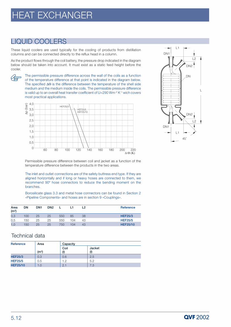
5.12
HEAT EXCHANGER
LIQUID COOLERSThese liquid coolers are used typically for the cooling of products from distillationcolumns and can be connected directly to the reflux head in a column.
As the product flows through the coil battery, the pressure drop indicated in the diagrambelow should be taken into account. It must exist as a static feed height before thecooler.
The inlet and outlet connections are of the safety buttress end type. If they arealigned horizontally and if long or heavy hoses are connected to them, werecommend 90º hose connectors to reduce the bending moment on thebranches.
Borosilicate glass 3.3 and metal hose connectors can be found in Section 2»Pipeline Components« and hoses are in section 9 »Couplings«.
Permissible pressure difference between coil and jacket as a function of thetemperature difference between the products in the two areas.
Technical dataArea
(m2)
0.30.51.0
Reference
HEF25/3HEF25/5HEF25/10
Coil(l)
0.61.22.1
Jacket(l)
2.55.27.3
Capacity
DN2
252525
DN
100150150
DN1
252525
L
550550750
L1
85104104
L2
384343
Area (m2)
0,30,51,0
Reference
HEF25/3HEF25/5HEF25/10
The permissible pressure difference across the wall of the coils as a functionof the temperature difference at that point is indicated in the diagram below.The specified ∆Θ is the difference between the temperature of the shell sidemedium and the medium inside the coils. The permissible pressure differenceis valid up to an overall heat transfer coefficient of U=290 Wm-2 K-1 wich coversmost practical applications.

5.13
HEAT EXCHANGER
LIQUID COOLERS
Pressure drop in the coil based on water at 20 ºC
Pressure drop diagram
300
240
180
120
60
00.1 0.2 0.3 0.4 0.5 0.6 0.7
HEF25/10
HEF25/5
HEF25/3
p (
mb
ar)
V (m³/h)•
∆
VENT CONDENSERSThese items are installed before vacuum pumps or in vent gas lines to remove anycomponents in vapour form still remaining in the gas stream after the main condenser.Their compact design makes them ideal for fitting directly in pipework without the needfor any reduction.
The permissible pressure difference across the wall of the coils as a functionof the temperature difference at that point is indicated in the diagram below.The specified ∆Θ is the difference between the temperature of the shell sidemedium and the medium inside the coils. The permissible pressure differenceis valid up to an overall heat transfer coefficient of U=290 Wm-2 K-1 wich coversmost practical applications.
4.0
3.5
3.0
2.5
2.0
1.5
1.0
0.5
0 60 80 100 120 140 160 180 200 220
p (
bar
)
∆Θ (Κ)
∆
HEC40/...HEC50/...HEC80/...
HEC200/...HEC300/...
HEC150/...HEC600/... HEC450/.
HEC100/5
Permissible pressure difference between coil and jacket as a function of thetemperature difference between the products in the two areas.

5.14
HEAT EXCHANGER
VENT CONDENSERSThe inlet and outlet connections are of the safety buttress end type. If they arealigned horizontally and if long or heavy hoses are connected to them, werecommend 90º hose connectors to reduce the bending moment on thebranches.
Borosilicate glass 3.3 and metal hose connectors can be found in Section 2»Pipeline Components« and hoses are in section 9 »Couplings«.
Pressure drop in the coil based on water at 20 ºC
Technical dataArea
(m2)
0.60.6
Reference
HEG25/6HEG50/6
Coil(l)
0.90.9
Jacket(l)
3.43.6
Capacity
DN
100100
DN1
2550
DN2
1515
L
800800
L1
100100
L2
125125
Area (m2)
0,60,6
Reference
HEG25/6HEG50/6
p (
bar
)∆
V (m³/h)•
HEG25/6HEG50/6
3.0
2.5
2.0
1.5
1.0
0.5
00.25 0.5 0.75 1.0 1.25 1.5 1.75 2.0 2.25 2.5 2.75

5.15
HEAT EXCHANGER
SHELL AND TUBE HEAT EXCHANGERSShell and tube heat exchangers provide a versatile alternative to the coil-type heatexchangers described on previous pages. They were conceived as condensers, but theyare equally suitable for heat transfer between two liquids or gases.
These shell and tube heat exchangers are of modular construction. They comprise thefollowing individual elements: tubular shell, headers, tube plates, heat exchange tubesand baffles. Sealing of the individual tubes in the tube plate is of particular importance.The threaded PTFE bushes and PTFE sealing rings provide a seal of the highest integritybetween the different materials.
Four basic versions of shell and tube heat exchanger, with PTFE tube plates andborosilicate glass 3.3 or silicon carbide heat transfer tubes, are available as standard.They are listed on pages 5.16 to 5.19.
Performance data which can be used to estimate the heat transfer surface required isgiven on page 5.21. We would be happy to carry out accurate calculations for you usingspecial programs.
The maximum permissible operating conditions in borosilicate glass 3.3 heatexchangers are detailed in the table below. If duties in excess of these figuresare called for, we recommend the use of the special versions described onpage 5.22.
The standard branch positions are as indicated in the appropriate diagrams.Alternative positions are available on request.
When making connections to the service necks on the heat exchangers,bellows should be used to avoid imposing any stresses.
When installing shell and tube heat exchangers appropriate precautionsshould be taken. Details of these can be found in the installation and operatinginstructions supplied with each item.
The standard version of these heat exchangers is designed to be installedhorizontally. If required, however, drain and venting facilities can be providedon the tube plates together with changes to the support arrangements on theunits to permit vertical installation (please see page 5.20).
The end form, which depends on the nominal size, is shown in the diagramon page 5.2. Further information can be found in Section 1 »TechnicalInformation«.
DN
150200300
Area
(m2)2,5-55-1012,5-25
Max. Temperaturedifference for Glass HeatExchanger Tubes(K)130130130
Permissibleoperatingtemperature
(°C)-50/+150-50/+150-50/+150
Permissible operating pressure(bar g)
Shell
-1/+2-1/+1-1/+1
Tube side../..S..G333
../..S..G444
../..G..G322
../..G..G433
Permissibledifferentialpressure fortube plate (bar)

5.16
HEAT EXCHANGER
SHELL AND TUBE HEAT EXCHANGERSShell and Tube Heat Exchangers, both sides corrosion resistantThere are two versions of this type of heat exchanger, single pass (version A) and triplepass (version B). Both versions combine borosilicate glass 3.3 (shell, heat exchangetubes and headers) and PTFE (tube plates, bushes and baffles). Included in the supplyare two support brackets which provide the basis for fixing to the support structure (seeassembly dimensions).
If silicon carbide heat exchange tubes are required, please replace theapplicable »G« in the catalogue reference with »S« (see Key to cataloguereferences). In these cases a prior check on the heat transfer area should becarried out.
Key to catalogue references
RBW 300 / 125 / G 3 G V
Vertical installation
Material of heat transfer tubes:G = Glass, S = SiC
Number of passes
Material of headers:G = Glass Area in m2 x 10
Nominal size
Reference
RBW150/25G..GRBW150/32G..GRBW150/40G..GRBW150/50G..G
RBW200/50G..GRBW200/63G..GRBW200/80G..GRBW200/100G..G
RBW300/125G..GRBW300/160G..GRBW300/200G..GRBW300/250G..G
DN
150150150150
200200200200
300300300300
Area (m2)
2.53,24,05,0
5,06,38,010,0
12,516,020,025,0
E2
620112016202120
917141719172417
521102115212021
E1
574574574574
677677677677
897897897897
E3
200200200200
200200200200
200200200200
E4
208208208208
243243243243
295295295295
d
14141414
14141414
14141414
Dimensions

5.17
HEAT EXCHANGER
SHELL AND TUBE HEAT EXCHANGERS
DN Area DN1 DN2 DN3 L L1 L2 L3 L4 L5 Type Reference(m2)
150 2.5 50 100 50 1774 332 1110 160 200 108 A RBW150/25G1G150 2.5 50 100 50 1774 332 1110 160 200 108 B RBW150/25G3G150 3,2 50 100 50 2274 332 1610 160 200 108 A RBW150/32G1G150 3,2 50 100 50 2274 332 1610 160 200 108 B RBW150/32G3G150 4,0 50 100 50 2774 332 2110 160 200 108 A RBW150/40G1G150 4,0 50 100 50 2774 332 2110 160 200 108 B RBW150/40G3G150 5,0 50 100 50 3274 332 2610 160 200 108 A RBW150/50G1G150 5,0 50 100 50 3274 332 2610 160 200 108 B RBW150/50G3G
200 5,0 80 150 50 2282 386 1510 175 250 138 A RBW200/50G1G200 5,0 80 150 50 2282 386 1510 175 250 138 B RBW200/50G3G200 6,3 80 150 50 2782 386 2010 175 250 138 A RBW200/63G1G200 6,3 80 150 50 2782 386 2010 175 250 138 B RBW200/63G3G200 8,0 80 150 50 3282 386 2510 175 250 138 A RBW200/80G1G200 8,0 80 150 50 3282 386 2510 175 250 138 B RBW200/80G3G200 10,0 80 150 50 3782 386 3010 175 250 138 A RBW200/100G1G200 10,0 80 150 50 3782 386 3010 175 250 138 B RBW200/100G3G
300 12,5 100 200 50 2318 504 1310 235 275 180 A RBW300/125G1G300 12,5 100 200 50 2318 504 1310 235 275 180 B RBW300/125G3G300 16,0 100 200 50 2818 504 1810 235 275 180 A RBW300/160G1G300 16,0 100 200 50 2818 504 1810 235 275 180 B RBW300/160G3G300 20,0 100 200 50 3318 504 2310 235 275 180 A RBW300/200G1G300 20,0 100 200 50 3318 504 2310 235 275 180 B RBW300/200G3G300 25,0 100 200 50 3818 504 2810 235 275 180 A RBW300/250G1G300 25,0 100 200 50 3818 504 2810 235 275 180 B RBW300/250G3G
Shell and Tube Heat Exchangers, both sides corrosion resistant

5.18
HEAT EXCHANGER
SHELL AND TUBE HEAT EXCHANGERSShell and Tube Heat Exchangers, shell side corrosion resistant
There are also two versions of this type of heat exchanger, single pass (version A) andtriple pass (version B). Both versions use borosilicate glass 3.3 (shell and heat exchangetubes) and PTFE (tube plates, bushes and baffles) in combination with stainless steelheaders. Included in the supply are two support brackets which provide the basis forfixing to the support structure (see assembly dimensions).
If silicon carbide heat exchange tubes are required, please replace theapplicable »G« in the catalogue reference with »S« (see Key to cataloguereferences). In these cases a prior check on the heat transfer area should becarried out.
Key to catalogue references
RBW 300 / 125 / S 3 G V
Vertical installation
Material of heat transfer tubes:G = Glass, S = SiC
Number of passes
Material of headers:S = SteelArea in m2 x 10
Nominal size
Reference
RBW150/25S..GRBW150/32S..GRBW150/40S..GRBW150/50S..G
RBW200/50S..GRBW200/63S..GRBW200/80S..GRBW200/100S..G
RBW300/125S..GRBW300/160S..GRBW300/200S..GRBW300/250S..G
DN
150150150150
200200200200
300300300300
Area(m2)
2.53,24,05,0
5,06,38,010,0
12,516,020,025,0
E2
620112016202120
917141719172417
521102115212021
E1
565565565565
691691691691
916916916916
E3
200200200200
200200200200
200200200200
E4
208208208208
243243243243
295295295295
d
14141414
14141414
14141414
Dimensions

5.19
HEAT EXCHANGER
SHELL AND TUBE HEAT EXCHANGERS
DN Area DN1 DN2 DN3 L L1 L2 L3 L4 L5 Type Reference(m2)
150 2.5 40 100 50 1750 320 1110 160 200 55 A RBW150/25S1G150 2.5 40 100 50 1750 320 1110 160 200 55 B RBW150/25S3G150 3,2 40 100 50 2250 320 1610 160 200 55 A RBW150/32S1G150 3,2 40 100 50 2250 320 1610 160 200 55 B RBW150/32S3G150 4,0 40 100 50 2750 320 2110 160 200 55 A RBW150/40S1G150 4,0 40 100 50 2750 320 2110 160 200 55 B RBW150/40S3G150 5,0 40 100 50 3250 320 2610 160 200 55 A RBW150/50S1G150 5,0 40 100 50 3250 320 2610 160 200 55 B RBW150/50S3G
200 5,0 50 150 50 2300 395 1510 175 250 77 A RBW200/50S1G200 5,0 50 150 50 2300 395 1510 175 250 77 B RBW200/50S3G200 6,3 50 150 50 2800 395 2010 175 250 77 A RBW200/63S1G200 6,3 50 150 50 2800 395 2010 175 250 77 B RBW200/63S3G200 8,0 50 150 50 3300 395 2510 175 250 77 A RBW200/80S1G200 8,0 50 150 50 3300 395 2510 175 250 77 B RBW200/80S3G200 10,0 50 150 50 3800 395 3010 175 250 77 A RBW200/100S1G200 10,0 50 150 50 3800 395 3010 175 250 77 B RBW200/100S3G
300 12,5 80 200 50 2350 520 1310 235 275 112 A RBW300/125S1G300 12,5 80 200 50 2350 520 1310 235 275 112 B RBW300/125S3G300 16,0 80 200 50 2850 520 1810 235 275 112 A RBW300/160S1G300 16,0 80 200 50 2850 520 1810 235 275 112 B RBW300/160S3G300 20,0 80 200 50 3350 520 2310 235 275 112 A RBW300/200S1G300 20,0 80 200 50 3350 520 2310 235 275 112 B RBW300/200S3G300 25,0 80 200 50 3850 520 2810 235 275 112 A RBW300/250S1G300 25,0 80 200 50 3850 520 2810 235 275 112 B RBW300/250S3G
Shell and Tube Heat Exchangers, shell side corrosion resistant

5.20
HEAT EXCHANGER
SHELL AND TUBE HEAT EXCHANGERS
Reference
RBW150/25..GVRBW150/32..GVRBW150/40..GVRBW150/50..GV
RBW200/50..GVRBW200/63..GVRBW200/80..GVRBW200/100..GV
RBW300/125..GVRBW300/160..GVRBW300/200..GVRBW300/250..GV
DN
150150150150
200200200200
300300300300
Area(m2)
2.53,24,05,0
5,06,38,010,0
12,516,020,025,0
E6
300300300300
305305305305
436436436436
E5
300300300300
375375375375
425425425425
d
42424242
42424242
42424242
E7
148148148148
168168168168
218218218218
Dimensions
Shell and Tube Heat Exchangers for vertical installationAll the heat exchangers described on pages 5.16 to 5.19 can also be supplied for verticalinstallation. The tube plates are then fitted with suitable venting and drainingarrangements. Included in the supply is also a support frame which provide the basisfor fixing to the support structure (see assembly dimensions).
In such cases a »V« should be added to the catalogue reference (see Key tocatalogue references) for the particular heat exchanger (see pages 5.17 to5.19).
Key to catalogue references
RBW 300 / 125 / S 3 G V
Vertical installation
Material of heat transfer tubes:G = Glass, S = SiC
Number of passes
Material of headers:S = Steel, G = Glass Area in m2 x 10
Nominal size

5.21
HEAT EXCHANGER
SHELL AND TUBE HEAT EXCHANGERS
Reference
RBW150/25..1..RBW150/32..1..RBW150/40..1..RBW150/50..1..
RBW200/50..1..RBW200/63..1..RBW200/80..1..RBW200/100..1..
RBW300/125..1..RBW300/160..1..RBW300/200..1..RBW300/250..1..
RBW150/25..3..RBW150/32..3..RBW150/40..3..RBW150/50..3..
RBW200/50..3..RBW200/63..3..RBW200/80..3..RBW200/100..3..
RBW300/125..3..RBW300/160..3..RBW300/200..3..RBW300/250..3..
Type of heat transfer
Liquid-liquid
Liquid-gas
Condensation
Fluid
Water-water
Water-organic solvent
Water-heat transfer oil
Water-air
Water-water
Water-organic solvent
Performance data
Technical data
Heat transf. coeff. (Wm-2 K-1) for tubes made of
An approximate calculation of heat transfer surface areas can be based on the followingguide figures for heat exchange values.
Area
(m2)
2,53,24,05,0
5,06,38,010,0
12,516,020,025,0
2,53,24,05,0
5,06,38,010,0
12,516,020,025,0
Number of Tubes(Ø14 x 1,5)-
37373737
61616161
163163163163
37373737
61616161
163163163163
Tubes
(cm2)
35353535
58585858
155155155155
11,711,711,711,7
19,319,319,319,3
51,651,651,651,6
Shell
(cm2)
120120120120
220220220220
456456456456
120120120120
220220220220
456456456456
Tubes andheaders(l)
9,010,012,514,0
19,022,025,028,0
53,561,069,075,5
9,010,012,514,0
19,022,025,028,0
53,561,069,075,5
Shell
(l)
18243036
47586980
94117140163
18243036
47586980
94117140163
Free cross sectional area Capacity
SiC650-1800
500-1400
400-800
15-90
1400-3100
900-2100
Glass330-560
300-500
220-400
15-90
520-640
400-580
Heat exchanger DN 300 with metal headers have only 162 tubes, because ofthe central plate support.

5.22
HEAT EXCHANGER
SHELL AND TUBE HEAT EXCHANGERSShell and Tube Heat Exchangers, special versionsBecause of the modular design of the standard heat exchangers (see page 5.15), a widevariety of alternative materials can also be supplied and this facilitates adaptation of theheat exchangers to the particular requirements of each case. Details can be found inthe table below and our special brochure which is available on request.
Additional features which can be supplied on request are:
- Turbulence devices for fitting in the heat exchange tubes. These increase heat transfer in the tubes by up to three times the normally attainable value.
- Double tube plates that ensure trouble-free separation of the shell-side and tube-side pressure area. Risks caused by leakage, for example the contaminationof the product by the heating or cooling fluid, are thus avoided. This is of importance above all else for plant which has to conform to GMP requirements.
Nominal size DN 50 - 450Heat exchange area m2 up to 60Outside diameter of internal tubes mm 14 or largerNumber of tube side passes - 1 - 4
Permissible Pressure bar g max. 10operating conditions Temperature ºC max. 180
Differential pressure bar max. 6(tube/shell)
Materials Shell - Borosilicate glass 3.3Stainless steel Steel, glass lined or coatedSpecial materials
Headers - Borosilicate glass 3.3Stainless steel Steel, glass lined or coated
Tube plates - PTFE, solidCORETHERM type
Bushes and - PTFEgaskets
Baffles - PTFEHeat exchange tubes - Borosilicate glass 3.3
Silicon carbideStainless steelSpecial materials

5.23
HEAT EXCHANGER
METAL - IMMERSION HEAT EXCHANGERS
Coil-Type - Immersion Heat Exchangers
Our range of metal immersion heat exchangers are used specifically in applicationswhere higher steam pressures and/or larger heat transfer surfaces are required.
The properties of the product should be taken into account when selecting the materialof construction (coil and circular ring immersion heat exchangers for example aresupplied as standard in stainless steel).
This versatile heat exchanger is used for the heating of spherical and cylindrical vessels(please see section 4 »Vessels & Stirrers«) and at the bottom of columns (please seesection 5 »Column Components«). The heating coil is welded to a bottom plate whichincorporates a branch with flange drilled to suit QVF PCD hole size and number. Hosescan be supplied for the steam and condensate connections (see section 9 »Couplings«).
Coil-type immersion heat exchangers are supplied as standard in stainless steel. Theyare also available, however, in hastelloy on request.
The maximum permissible operating pressure for these coil-type immersionheat exchangers is 20 bar g and the maximum operating temperature is 300ºC (PN 40 steam and condensate connection, EN 1092).
Reference
EH150/1.5EH150/2.5EH200/2.5EH200/5EH200/8EH200/10EH200/15EH300/15EH300/20EH300/30
DN
150150200200200200200300300300
DN1
25254040404040404040
Area(m2)0,150,250,250,50,81,01,51,52,03,0
D
145145170170170170170250250250
DN2
2 x 252 x 252 x 252 x 252 x 252 x 252 x 252 x 252 x 252 x 25
D1
274274321321321321321420420420
L2
166166166166166166166171171171
L1
2353752553805556559305557051005
L
210210210210210210210215215215
L4
120120120120120120120170170170
Capacity (l)1,01,61,82,73,94,66,66,58,010,0
L3
106106106106106106106106106106

5.24
HEAT EXCHANGER
METAL - IMMERSION HEAT EXCHANGERSCircular Ring Type - Immersion Heat ExchangersThese items are recommended for use in spherical vessels as they yield high heattransfer and evaporation performance in conjunction with a turbine stirrer fitted centrally.The forced circulation across the heat transfer surface results in evaporation down to avery low residual volume. Other advantages are the smooth surface, the baffle fittedinside to create turbulence and the integral branch with QVF taper for a »BAS40«borosilicate glass 3.3 bottom outlet valve (see section 3 »Valves«). Hoses can besupplied for the steam and condensate connections (see chapter 9 »Couplings«).
Circular ring immersion heat exchangers are supplied as standard in stainless steel. Theyare also available, however, in titanium, tantalum or hastelloy on request.
The maximum permissible operating pressure for circular ring immersion heatexchangers is 6 bar g and the maximum operating temperature is 200 ºC (PN40 steam and condensate connection, EN 1092).
Reference
KRH200/1.5KRH200/2KRH200/2.5KRH300/3KRH300/3.5KRH300/4KRH300/4.5KRH300/5
DN
200200200300300300300300
DN1
4040404040404040
Area(m2)0,150,20,250,30,350,40,450,5
D
155155155235235235235235
DN2
2 x 252 x 252 x 252 x 252 x 252 x 252 x 252 x 25
D1
321321321420420420420420
L2
969696100100100100100
L1
225285340295330370405445
L
261261261265265265265265
L4
151151151210210210210210
Capacity(l)0,751,01,253,03,54,04,55,0
L3
100100100100100100100100

5.25
HEAT EXCHANGER
METAL - IMMERSION HEAT EXCHANGERSBayonet Type - Immersion Heat ExchangersThere is a very wide range of applications for this type of heat exchanger, particularlywhere a high level of corrosion resistance is required. Typical applications include useas boilers in circulatory evaporators and for heating columns. The design incorporatingmultiple bayonets ensures good heat transfer even when larger heat transfer surfacesare involved.
Bayonet immersion heat exchangers can be supplied in nominal sizes DN 80 to DN 600with heat transfer areas from 0.05 to 8.5 m2.
The base of these boilers is designed to act as a vapour distributor and condensatecollector. A branch drilled to suit QVF PCD hole size and number welded through thebase serves as a product connection. Hoses can be supplied for the steam andcondensate connections (please see chapter 9 »Couplings«).
Bayonet immersion heat exchangers are supplied in tantalum as standard. Othermaterials are, however, also available.
The maximum permissible operating pressure for bayonet immersion heatexchangers is 10 bar g and the maximum operating temperature is 210 ºC (PN40 steam and condensate connection, EN 1092 ).

6 COLUMN COMPONENTS
PROCESS PLANT COMPONENTS
P 306 e.3 Copyright © 2007, QVF Engineering GmbH. All rights reserved.

6.2
COLUMN COMPONENTS
IntroductionQVF column components provide the optimum solution for every requirementencountered in practice for operations such as distillation, rectification, absorption,reaction and extraction because of the wide range of different components available.This applies not only to the various types of column and pipe sections available (plainand jacketed and with or without internals) but also to the wide selection of internalsand random and structured packing that can be supplied.
These components are widely used in the chemical, pharmaceutical and allied industriestogether with other applications such as food and drink production, dye works andelectroplating. This is because of the special properties of borosilicate glass 3.3 andPTFE together with the special materials that are used in some instances for internals,plus the fact that borosilicate glass 3.3 is an approved and proven material ofconstruction for pressure vessels.
Reference should also be made in this context to the extreme reliability of the strongand high-duty coupling system used for all components. This is achieved throughoutthe whole range of nominal sizes by the use of the safety buttress end which has beendesigned specifically taking into account the properties of the material, coupled with areliable flange system.
The complete range of standard column components is described on the followingpages. Non-standard components can also be supplied to special order. Columnsections and fittings in other materials (glass-lined steel etc.) can also be supplied onrequest.
A detailed listing of all column components by »Description« and »Catalogue Reference«can be found in the »Index«.
Detailed information on a number of the topics referred to in the followingpages can be found in Section 1 »Technical Information«.
Further information on complete columns can be found in our special leafletsdealing with individual unit operations.
Details of the design of the different types of optimised buttress ends areillustrated alongside.
GMP compliant installationsThe use of columns and the layout of interconnecting pipeline incorporating valves whendesigning plant and equipment complying with GMP regulations, calls for special carein both the planning and selection of the components together with the materials ofconstruction used for them. Borosilicate glass 3.3 has a number of special propertiesthat are highly valued in the pharmaceutical industry and these in conjunction withmaterials approved in accordance with the FDA catalogue such as glass-lined steel(special versions of large bore column bottom sections), PTFE (redistributors andpacking retainers) and special materials (e.g. internals) ensure that any build-up ofunwanted deposits is avoided in areas which come in contact with the product. A designwithout any dead space, which ensures that components drain fully and can be cleanedeasily and effectively, is achieved by the shape of the components, the way they areinstalled and the selection of suitable valves. Where the external surfaces of completeassemblies have to comply with clean room requirements, appropriate stainless steelcoupling and support material can be supplied (please see Section 9 »Couplings« andSection 10 »Structures and Supports«).
We would be happy to advise you on the basis of the regulatory requirements applicableto a particular case and the guidelines drawn up by us for the design of GMP compliantplant.
DN15 - DN150
DN200 - DN300
DN450 - DN1000

6.3
COLUMN COMPONENTS
Glass components suitable for higher permissible operating conditions can besupplied on request.
Coated column componentsDamage to borosilicate glass 3.3 plant resulting from accidental external causes cannotbe entirely excluded. This is primarily due to the relatively rigorous conditions prevalentin production plants and applies especially where no additional protection is providedin the form of insulation.
Our answer to this problem is to provide borosilicate glass 3.3 column components witha Sectrans transparent coating. This can be applied irrespective of the shape of thecomponent and it provides additional protection without having any adverse effect onvisual monitoring of the process.
A glass fibre reinforced polyester coating providing a higher level of protection can alsobe supplied on request. This does have a slightly adverse effect on the transparency ofthe glass, making it translucent and not transparent.
Permissible operating conditionsWhile the maximum permissible operating temperature for all borosilicate glass 3.3column components is generally 200 ºC (∆Θ • 180 K, the maximum permissible operatingpressure is governed by the main nominal size of the component but not by its shape.Detailed information on this and the operation of jacketed components can be found inSection 1 »Technical Information«.
The permissible operating conditions for components in other materials can be foundin the respective product description.

6.4
COLUMN COMPONENTS
Depending on the nominal size, column sections are supplied in 1000 and/or 1500 mmlengths, and also with or without a thermometer branch. They have an integral shelf onwhich the packing support rests. A PTFE ring is fitted between the support shelf andpacking support to prevent direct contact between the two parts.
Column sections can be filled with random packing or alternatively structured packingif the free cross sectional area of the packing support is large enough (please see page6.5), For structured packing higher free cross sectional areas can be achieved by theuse of »CSDU..« type column sections (please see page 6.12).
Higher free cross-sectional areas can be achieved in the DN 80 to DN 300 nominal sizerange by combining pipe sections (please see section 2 »Pipeline Components«) with»LBE..« type packing supports (please see page 6.8). Use of pipe sections and specialtypes of support plates is possible across the whole range of nominal sizes. For largerdiameters, the patented support CORE-TRAY is available, which also serves as fluidcollector and distributor. Column sections with structured packing, such asDURAPACK® high performance borosilicat glass 3.3 packing, described on page 6.12are an example of this type of application.
Pipe sections can also be used to extend the length of column sections i.e. to increasethe packed height, provided the permissible load-bearing capacity of the packingsupport is not exceeded.
Column sections suitable for installing distribution plates as well as packing retainers aredescribed on pages 6.6 and 6.10. Precision bore pipe sections with and withoutbuttress ends for special internals or chromatography columns can be found on page6.32.
Jacketed column sections can also be supplied on request.
All column sections are supplied complete with a packing support. Randompacking (please see page 6.9) and structured packing (please see page 6.10and 6.11), should be ordered separately.
Details of free cross-sections (including packing support), the load-bearingcapacity of the support rings in conjunction with the supplied packing supportsand the recommended packing can be found in the table on the followingpage. The free cross-section of individual components used to constructcolumns and the load-bearing capacity of the packing supports is indicatedin the description of the product in question.
The minimum size of random packed or stacked raschig rings can also befound in the table on the following page. Where raschig rings of smaller sizesare used a layer of high performance DURAPACK® should be installed first.
In the table below »DN« refers to the nominal size of the column.
For manufacturing reasons on column sections in DN 800 and DN 1000nominal sizes in which the support shelf also acts as a redistributor thethermometer branch can only be located below the upper buttress end.
COLUMN SECTIONS

6.5
COLUMN COMPONENTS
COLUMN SECTIONS DN
80100150200200 3003004506008001000
Cat.Reference
with thermo-meter branchCST80/1000CST100/1000CST150/1000CST200/1000CST200/1500CST300/1000CST300/1500CSTN450/1500CSTN600/1500CSTN800/1500CSTN1000/1500
Cat. Reference
without thermo meter branchCS80/1000CS100/1000CS150/1000CS200/1000CS200/1500CS300/1000CS300/1500CSN450/1500CSN600/1500CSN800/1500CSN1000/1500
DN1
2525252525252525254040
L
10001000100010001500100015001500150015001500
L1
108122147171171221221299377562650
L2
9196111111111111111151151248250
H
835840830830133082513251234120911051081
Free cross-section (%)
3236344545565644535556
Type
AAABBBBBBCC
Load bearingcapacity (N)
23035070090090010001000305039501050012500
Minimum size of packing (FC)
random packed, stacked FC8 -FC10 -FC15 FC20FC20 FC20FC20 FC20FC25 FC30FC25 FC30FC50 FC50FC50 FC50 FC50 FC50FC50 FC50

6.6
COLUMN COMPONENTS
COLUMN SECTIONS FOR LIQUID DISTRIBUTION TRAYSIrrespective of the nominal size these column sections are supplied in one length onlyso that they still provide sufficient height for random or structured packing. They havethree extra side branches offset at 120º from each other so that a nozzle typedistributor can be fitted to redistribute the liquid. These are located at an appropriateheight so that a PTFE redistributor (please see page 6.16) can be installed in thecoupling above the distribution plate.
These column sections can be supplied with or without thermometer branch.
All column sections are supplied complete with packing support. Distributiontrays, random packing (please see page 6.9) and structured packing (pleasesee page 6.11) should be ordered separately.
Further technical information and dimensions can be found on page 6.5,where »CS..« and »CST..« type column sections are described.
DN
200300450600
Reference
with thermo-meter branchCSVT200/1500CSVT300/1500CSVTN450/1500CSVTN600/1500
Reference
withoutthermometerbranchCSV200/1500CSV300/1500CSVN450/1500CSVN600/1500
DN1
25252525
DN2
25254040
L
1500150015001500
H
1330132512341209
H1
150165205255
L1
171221299377
L2
111111151151
L3
110125135175
L4
165218300380

6.7
COLUMN COMPONENTS
PACKING SUPPORTS FOR RANDOM PACKED COLUMN SECTIONS
Packing supports for structured packing can be found on page 6.16.
In the table below »DN« refers to the nominal size of the column.
For nominal sizes up to DN 300 we supply »LB..« borosilicate glass 3.3 packingsupports for the column sections described on pages 6.5 and 6.6. For larger diameterswe provide type »HD..« packing supports for which a combination of glass and PTFEis used.
As packing supports are always supplied as part of the column section assembly, theyare normally only ordered separately when required as replacements. The PTFE ring onwhich they are seated is supplied complete with the support.
Details concerning free cross-sections of the supports and their load-bearing capacitieswhen loaded evenly and on the minimum size of packing to be used are given on page 6.5.
ReferenceLB80LB100LB150LB200LB300HD450HD600HD800HD1000
L21213131316691133153
D7095140190270440590790968
E7713172233333939
TypeAAAAABBBB
DN801001502003004506008001000

6.8
COLUMN COMPONENTS
PACKING SUPPORTS FOR RANDOM PACKED PIPE SECTIONS
Reference
LBE80LBE100LBE150LBE200LBE300
L
2525505050
DN
80100150200300
These items are used with pipe sections (please see section 2 »Pipeline Components«).This alternative provides larger free cross-sections than the combination of columnsections with packing supports. In addition to the glass support plate the supply alsoincludes the special backing flange with special insert, screwed rods, nuts andcompression springs.
Details concerning free cross-sections of the supports and their load-bearing capacitieswhen loaded evenly can be found in the table below.
Free cross-section (%)
5672778181
E
77131821
Type
AAABB
Load bearingcapacity (N)
700900100011001200
Minimum size of packing (FC)
random packed stackedFC 8 -FC10 -FC15 FC20FC20 FC20FC25 FC30

6.9
COLUMN COMPONENTS
COLUMN PACKINGIn addition to the borosilicate glass 3.3 raschig rings shown here, we can also supplyother column packing in materials and geometries to suit the individual application. Wewould be happy to assist you in the selection of suitable packing and the design of thecolumns.
Borosilicate glass 3.3 structured packing (DURAPACK®) can be found on pages 6.11.
Column sections with bubble-cap plates are shown on page 6.30 onwards.
The permissible height of the packing is restricted by the load-bearing capacityof the packing support fitted in the column section (please see page 6.5).
Reference
FC8FC10FC15FC20FC25FC30FC40FC50
s
1,01,01,21,21,41,42,02,5
Bulk density random (kg/m3)
packed stacked 660 - 520 -435 -345 -290 -275 325300 360260 335
Surface random(m2/m3)
packed stacked 633 -487 -331 -259 -186 -173 205135 16293 120
Free volume random (%)
packed stacked 69 -75 -79 -83 -86 -86 8485 8387 84
D x H
8 x 810 x 1015 x 1520 x 20 25 x 2530 x 30 38 x 3850 x 50

Mass transfer in absorption, desorption, rectification and extraction columns can beimproved by the use of structured packing in various materials. They provide highthroughput coupled with low pressure drop and at the same time ensure goodseparation efficiency.
The DURAPACK® borosilicate glass 3.3 mass transfer packing referred to herecombines these benefits with the ability to handle very corrosive and/or high purityproducts. Further information such as areas of application, pressure drop, separationefficiency and flooding point can be found in our special brochure "DURAPACK®Borosilicate Glass 3.3 Structured Mass Transfer Packing”.
Complete couplings with longer bolts are required for column sections withstructured packing installed, this is because of the support rings and packingrestraints clamped between the flat buttress ends. These can be found in thesection 9 »Couplings«.
We would be happy to provide advice on process engineering design aspectsand the selection of suitable components for your particular application.
6.10
COLUMN COMPONENTS
STRUCTURED PACKING
PACKING RETAINERS
L
556644577
DN
801001502003004506008001000
Reference
CPC80CPC100CPC150CPC200CPC300CPCN450CPCN600CPC800CPC1000
These components are installed above packed column sections to prevent damage toreflux separators or condensers by the carry-over of column packing. They are in theform of a PTFE ring of selected quality with a tantalum wire mesh.
Packing retainers are installed in the same way as gaskets between two buttress endsand therefore no additional gasket is required.
Packing retainers should not be used in place of packing supports (please seepage 6.7).
E
101010182020303037
Free cross-section(%)658590808585959590

6.11
COLUMN COMPONENTS
D
90140190285435585798973
DN
1001502003004506008001000
Reference
DUPA100/300DUPA150/300DUPA200/300DUPA300/300DUPA450/300DUPA600/300DUPA800/300DUPA1000/300
The individual corrugated glass plates are homogeneously fused together to form flowchannels inclined at an angle of 45º to each other. The specific surface area is 300 m2/m3. Further information about pressure drop, separation efficiency and floodingthroughput can be found in our special brochure (please see page 6.10).
In the DN 100 to DN 450 range of nominal sizes, the packing elements are one-piece.In the larger sizes they are segmented. They can be used in column sections and pipesections (please see section 2 »Pipeline Components«) and they are installed usingspecial edge seals which are included in the supply (two seals up to DN 300 and oneabove DN 300 size).
The one-piece packing is supported on a PTFE support ring (steel reinforced in DN 450and above) and the segmented packing is supported on a combination of support ringand packing support (please see pages 6.13 and 6.16). The support rings are clampedbetween the buttress ends and also serve as gaskets.
For larger diameters, the patented support CORE-TRAY is available, which also servesas fluid collector and distributor.
H
200200200200200200200200
Weight ofone layer
(kg)0,51,32,35,212,122,440,260,0
Number of segments in a layer
11111447
DURAPACK®-ElementsSTRUCTURED PACKING
On request we can also supply DURAPACK® elements in different sizes or forlarger diameters (e.g. glass-lined columns) as well as structured packing inother materials of construction.
The installation of DURAPACK® mass transfer packing calls for considerableexperience and requires a certain amount of fitting work (make-up rings,retainers, drilling of holes for measurement probes). Any elements suppliedincluding accessories should, therefore, only be installed by our trainedinstallation personnel on the actual site. The maximum packing height shouldnot exceed 3 metres.
Where the packing elements are not intended for use in glass pipes, pleaseconsult us because of the possibility of varying diameters and the possibleneed for adaptation of the edge seal.
In the tables below »DN« refers to the nominal size of the pipe in which thepacking is installed.

6.12
COLUMN COMPONENTS
COLUMN SECTIONS FOR STRUCTURED PACKING
ReferenceCSDU100CSDU150CSDU200CSDU300CSDU450CSDU600CSDU800CSDU1000
DN12525252525254040
DN1001502003004506008001000
In the DN 100 to DN 1000 nominal bore range special column sections withthermometer branch can be supplied for structured packing such as the high efficiencyDURAPACK® packing described on page 6.11. Compared with the »CS..« type (seepage 6.5) they provide a significantly larger free cross sectional area and are, therefore,more suitable for internals of the type mentioned.
To ensure that the structured packing is installed properly in these column sections wesupply not only special support grids and rings (see page 6.16 and 6.13) but also otherrequired elements such as restrainers and spacer rings (see page 6.15).
L10001000100010001000100010001000
L1295295295290230230215215
L2122147171221299377562650
To connect column sections containing structured packing to each other andto other glass components »CPDU..« or »CCSFDU..« couplings (see section9 »Couplings«) with longer bolts are required because of the additional itemssuch as support rings and restrainers clamped between the buttress ends.
The end form, which depends on the nominal size is shown in the diagram onpage 6.2. Further information can be found in section 1 »TechnicalInformation«.

6.13
COLUMN COMPONENTS
Reference
SPS100SPS150SPS200SPS300
D
80130180275
DN
100150200300
L
12141520
packed height
1m DUPA1m DUPA1m DUPA1m DUPA
Load bearingcapacity (N)
3578140315
Free cross-section (%)
64758184
The permissible loads for support rings and the packed heights applicable tostructured packing indicated in the following tables should not be exceeded.
Above an operating temperature of 150 ºC and with packed heights of morethan one metre, PTFE-sheathed steel rings (please see page 6.14) must alsobe used in the DN 100 to DN 300 nominal size range.
Where segmented packing is used (e.g. with DURAPACK® in the DN 600 toDN 1000 nominal size range) »SPP..« packing supports (please see page 6.16)should also be used in addition to the support rings.
PTFE (DN 100 to DN 300) or steel/PTFE (DN 800 and DN 1000) support ringsare also used as packing restrainers (please see page 6.15).
SUPPORT RINGS FOR STRUCTURED PACKING
SUPPORT RINGS FOR STRUCTURED PACKING
Support rings are generally used to support structured packing such as highperformance DURAPACK® packing (please see pages 6.10 and 6.11) in pipe sections.Up to DN 300 nominal size they are made of selected quality PTFE. In larger nominalsizes PTFE-sheathed steel rings are used. These also act as a support flange for thecolumn section. In the DN 800 and DN 1000 nominal sizes there is also the alternativepossibility to combine the support ring with a fixed-point flange with the latter supportedon a steel angle substructure. Further information to this can be found in section 10»Structures and Supports«.
Support rings are clamped between the buttress end faces using longer bolts in thecoupling. The rings have a bead on both faces, so that no additional gasket is required.
PTFE Support Rings

6.14
COLUMN COMPONENTS
SUPPORT RINGS FOR STRUCTURED PACKINGSteel/PTFE Support Rings
DN
1001502003004506008001000
Reference
SPSH100SPSH150SPSH200SPSH300SPSH450SPSH600SPSH800SPSH1000
D
80130180275380520725910
K
1782542954005857109501120
K1
254295400495710850--
L
1820222227332525
Free cross-section (%)
6475818471758283
Type
AAAABCDD
n x d1
6 x M86 x M108 x M812 x M816 x M820 x M1224 x 1428 x 14
n x d2
3 x 113 x 113 x 113 x 143 x M123 x M16--
packedheight
3m DUPA3m DUPA3m DUPA3m DUPA3m DUPA2m DUPA2m DUPA2m DUPA
To suit to support frame
RRD150 a. 150/1.25RRD200RRD300RRDN400 a. 400/2RRDN600 a. 600/2.5U-Profile-Frame--
Load bearingcapacity (N)
1052354159352100249044256915

6.15
COLUMN COMPONENTS
SPACER RINGS FOR STRUCTURED PACKING
Reference
SPC100/2SPC100/5SPC150/2SPC150/5SPC200/2SPC200/5SPC300/2SPC300/5SPC450/2SPC450/5SPC600/2SPC600/5SPC800/5SPC800/8SPC1000/5SPC1000/8
D
9696145145195195291291440440592592798798973973
d1
8080130130180180275275380380520520725725910910
H
2525252525255858
Free cross-section %
64647575818184847171757582828383
DN
10010015015020020030030045045060060080080010001000
Structured packing such as high efficiency DURAPACK® packing (please see page6.11) must always be very carefully fixed after installation in column sections. Otherwisethere is the risk of relative movement between the jacket and the internals should anypressure surges occur which could result in damage to the packing elements withconsequent loss of performance or even disruption of operation.
For this reason, one or more spacer rings should be inserted above a section ofstructured packing to fill any free space between the internals and a restrainer (pleasesee below) clamped between the buttress ends in the upper coupling. These spacerrings are made of selected quality PTFE.
It is advisable to have a variety of rings available in different thicknesses to ensure thatthe free space can be filled to optimum effect.
Structured packing such as high efficiency DURAPACK® packing (please see page6.11) must always be very carefully fixed after installation in column sections. Otherwisethere is the risk of relative movement between the jacket and the internals should anypressure surges occur and this could result in damage to the packing elements withconsequent loss of performance or even disruption of operation.
For this reason, after the packing elements have been installed and spacer rings havebeen carefully fitted to take up any free space, a restrainer should be fitted in the couplingabove the structured packing. In DN 100 to DN 300 and DN 800 and DN 1000 columnsections the support rings described on page 6.13 and 6.14 also act as restrainers. Inthe DN 450 and DN 600 nominal bores the components described below, whichperform a similar function, should be used. These are made of selected quality PTFE.
In the table below »DN« refers to the nominal size of the column.
RESTRAINERS FOR STRUCTURED PACKING
Reference
SPST450SPST600
Free cross-section (%)
7175
DN
450600
D
380520
L
1515
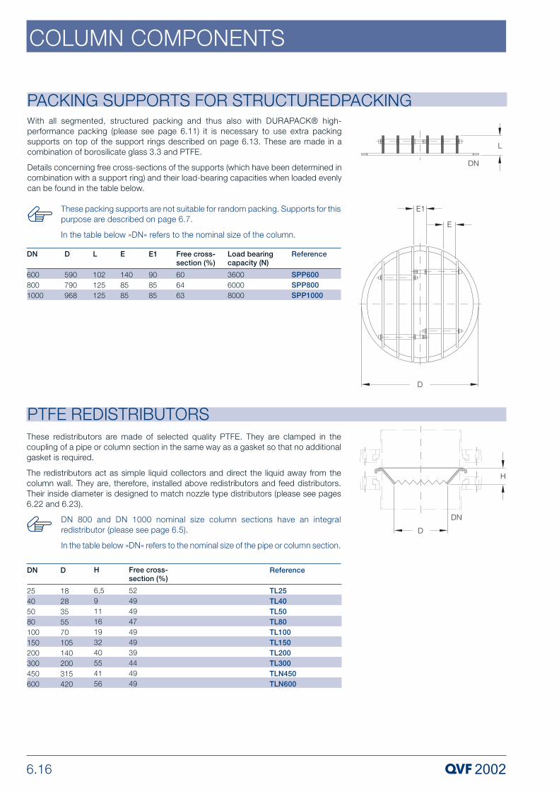
6.16
COLUMN COMPONENTS
PTFE REDISTRIBUTORS
Reference
TL25TL40TL50TL80TL100TL150TL200TL300TLN450TLN600
Free cross-section (%)
52494947494939444949
DN
25405080100150200300450600
D
1828355570105140200315420
H
6,591116193240554156
These redistributors are made of selected quality PTFE. They are clamped in thecoupling of a pipe or column section in the same way as a gasket so that no additionalgasket is required.
The redistributors act as simple liquid collectors and direct the liquid away from thecolumn wall. They are, therefore, installed above redistributors and feed distributors.Their inside diameter is designed to match nozzle type distributors (please see pages6.22 and 6.23).
PACKING SUPPORTS FOR STRUCTUREDPACKING
D
590790968
DN
6008001000
Reference
SPP600SPP800SPP1000
With all segmented, structured packing and thus also with DURAPACK® high-performance packing (please see page 6.11) it is necessary to use extra packingsupports on top of the support rings described on page 6.13. These are made in acombination of borosilicate glass 3.3 and PTFE.
Details concerning free cross-sections of the supports (which have been determined incombination with a support ring) and their load-bearing capacities when loaded evenlycan be found in the table below.
L
102125125
E
1408585
Free cross-section (%)
606463
Load bearingcapacity (N)
360060008000
E1
908585
These packing supports are not suitable for random packing. Supports for thispurpose are described on page 6.7.
In the table below »DN« refers to the nominal size of the column.
DN 800 and DN 1000 nominal size column sections have an integralredistributor (please see page 6.5).
In the table below »DN« refers to the nominal size of the pipe or column section.

6.17
COLUMN COMPONENTS
COLUMN FEED PIPES
COLUMN FEED PIPES
These feed pipes can be used in diameters and types of column where it is acceptablefor the liquid feed to be directed in a single stream onto the column packing.
Straight feed pipes are used as well as spray feed pipes in extraction columns tointroduce the phase to be dispersed and the continuous phase.
Angled feed pipes can be used in any application where it is acceptable for the liquidfeed to be directed in a single stream onto the column packing. They are usuallyinstalled via an unequal tee piece (please see section 2 »Pipeline Components«). Theyshould not, however, be used with distribution trays.
Straight Feed Pipes
Angled Feed Pipes
ReferenceFPS80/40FPS80/50FPS100/40FPS100/50FPS150/40FPS150/50FPS200/40FPS200/50FPS300/40FPS300/50FPS450/80FPS600/150
DN2252525252525252525254050
DN14050405040504050405080150
DN8080100100150150200200300300450600
L100100100100100100100100100100125200
L1100115125125150150175175225225325450
ReferenceFP80/40FP80/50FP100/40FP100/50FP150/40FP150/50FP200/40FP200/50FP300/40FP300/50FP450/80FP600/150
DN2252525252525252525254050
DN14050405040504050405080150
DN8080100100150150200200300300450600
L100100100100100100100100100100125200
L1100115125125150150175175225225325450
d13,413.413,413,413,413,413,413,413,413,424,037,4

6.18
COLUMN COMPONENTS
SPRAY FEED SECTIONS WITH BUILT-IN FEED PIPEWhere there is a requirement for a finer initial distribution of the liquid stream than canbe obtained with a column feed pipe (please see page 6.17) a spray feed section withbuilt-in feed pipe can be used in the DN 100 to DN 300 nominal size range. Thiscomponent delivers the liquid to the column in the form of a ring. Spray feed pipes forDN 450 and DN 600 nominal size columns can be found below.
These one-piece components comprise an unequal tee piece with a fused-in spray typefeed pipe. They make it possible to use a spray type feed even in small and medium sizecolumns.
For more specialised requirements tray, tube and nozzle type distributors can besupplied (please see pages 6.19 to 6.23).
In the table below »DN« refers to the nominal size of the column.
ReferenceFR100FR150FR200FR300
n x d120 x 227 x 227 x 230 x 3
TypeAABB
DN100150200300
DN125252525
D457090100
L250250250300
L1110150175220
Reference
FD450FDN600
n x d
40 x 360 x 3
L2
250400
for use with DN450600
DN1
150150
DN2
5050
L
200200
L1
500650
For DN 450 and DN 600 nominal size columns these spray feed pipes are used insteadof column feed pipes to provide a finer initial distribution of the liquid stream in the formof a ring. A version suitable for smaller columns can be found above.
This design, which can only be used with larger column sizes, facilitates the fitting andremoval of the spray feed pipe without the need for any extensive dismantling work. Thismakes adaptation to changes in operating conditions a very simple matter.
For more specialised requirements tray, tube and nozzle type distributors can besupplied (please see pages 6.19 to 6.23).
SPRAY FEED PIPES

6.19
COLUMN COMPONENTS
All the irrigation densities indicated in this section refer to our standard version.On request, we can also supply distributors for other values.
The end form, which depends on the nominal size is shown in the diagram onpage 6.2. Further information can be found in section 1 »TechnicalInformation«.
LIQUID DISTRIBUTORS To create the conditions required for optimum mass transfer in larger nominal sizecolumns through even distribution, we recommend the use of special components bothfor the first feed distribution and also redistribution in the column. Depending on theparticular duty we can supply borosilicate glass 3.3 column components with sealed-intube and channel type distributors as well as nozzle type distributors in a combinationof borosilicate glass 3.3 and PTFE. The latter are fitted in distributor sections (please seepage 6.23) for feed distribution duties or for use as redistributors in special columnsections (please see page 6.6).
The following criteria have an important bearing on the selection of the appropriate liquiddistributor:
– Process conditions such as pressure, temperature, F factor and irrigation density Bmax
– Column diameter and type of packing
– System properties where a distinction should be made between clean (C=clean) and slightly soiled (S=soiled) systems
Liquid distributors can be selected from the table below on the basis of the nominal sizeof the column, irrigation density and system properties. Further data can be found in theindividual product descriptions.
Tube type distributors
FTDDN150200300450600-------
Channel distributors
FCDDN-----300450600----
Nozzle distributors
FVA,FVDN--------200300450600
System characteristic
CCCCCC + SC + SC + SC + SC + SC + SC + S
Bmax
approx.
(m3/m2h)
211716172212121043567988

6.20
COLUMN COMPONENTS
LIQUID DISTRIBUTORS
ReferenceFCD300FCD450FCD600
DN12525505050
DN3004506008001000
L400550600700700
L2275350450775850
n x d32 x 378 x 3128 x 3200x3328x3
L1175200225350350
Channel Distributors
Technical Data
Where good distribution of the liquid over the whole cross section of the column isrequired with low irrigation densities we recommend the use of a channel distributor. Theitems described here are especially suitable for feed distribution of the liquid with all typesof structured packing. On request, we can also supply them with an integral collectingtray for use as redistributors.
Channel distributors are one-piece borosilicate glass 3.3 components which can befitted in columns without the need for any special adaptation. The liquid flows throughdrilled holes aligned in a downward direction and also through overflow pipes. The latterstart to work from 40% (stage 2) or 75 % (stage 3) respectively of the maximum irrigationdensity onwards.
In the event of overloading, the liquid backs up along the whole length and runs off overthe channel edges ensuring that irrigation of the column cross section is achieved overa large surface. Good drainage of any remaining liquid is ensured by appropriate sizingof the draining holes.
Special versions of these distributors can be supplied on request, i.e. with drop pointsdiffering from those indicated in the table below (diameter and number of holes andoverflow pipes) and also in nominal sizes DN 800 and DN 1000.
Free cross-section (%)6366646062
DN
3004506008001000
B(m3/m2h)3,5 – 12
3 – 122,5 – 100,6 – 7,90,6 – 8,3
Number of drop points per m2
283 – 452289 – 490240 – 452216 – 400219 – 418
TypeAAABB

6.21
COLUMN COMPONENTS
LIQUID DISTRIBUTORS Tube Distributors This distributor is designed for use with DURAPACK® high performance packing (pleasesee page 6.11). It guarantees a particularly even distribution over the cross section ofthe column for average irrigation densities by the overflow height in the overflow pipedepending on the particular throughput. It is, therefore, particularly suitable for feeddistribution with all types of structured packing. In addition, it can also be used forredistribution, if for example an »RDA..« type reflux separator is fitted above it as acollector.
Tube distributors are one-piece borosilicate glass 3.3 components which can be fittedin columns without the need for any special adaptation. The liquid flows through holesaligned in a downward direction. The horizontal tube is inclined downwards slightly toensure good drainage.
Special versions of these distributors can be supplied on request, i.e. with drop pointsdiffering from those indicated in the table below (diameter and number of holes).
ReferenceFTD150FTD200FTD300FTD450FTD600
DN12525508080
DN150200300450600
L300400400400600
n x d9 x 2,511 x 2,517 x 341 x 375 x 3
L1150175300375475
Technical DataFree cross-section(%)6458645951
DN
150200300450600
B(m3/m2h)2,5 – 212,5 – 172,5 – 162,5 – 172,5 – 22
Number of drop points per m2
509350240258265

6.22
COLUMN COMPONENTS
LIQUID DISTRIBUTORS
ReferenceFVA200FVA300FVA450FVA600
DN140508080
DN200300450600
DN225254040
D140231350470
L350450525600
L1125150200200
DN325252525
L3140165214215
L2170230320400
L4165215295375
L6110125135175
H72876997
H16060100110
L5250300390470
Nozzle distributors for feed distribution
Technical Data
This type of distributor is ideal for high irrigation densities and widely varyingthroughputs. Good distribution of the liquid over the column cross section is ensured inboth cases.
Nozzle distributors for feed distribution are a combination of borosilicate glass 3.3 andPTFE (nozzles only). The nozzles have lateral slits and are inserted separately in asupport tray. They can, therefore, be replaced if required. The tray in turn is located onthree support fingers positioned at 120º to each other and adjustable by means of aflexible gasket (see section 9 »Couplings«). A PTFE ring is fitted to prevent direct contactbetween the tray and the support fingers. Holes are designed to ensure good drainagewhen empty.
When a nozzle distributor is used for redistribution purposes an »RDA..« type refluxseparator should be fitted above it with the inlet branch DN1 closed off. As an alternativewe can supply the nozzle distributors described on page 6.23 which can be installed indistributor sections or column sections specially designed for the purpose.
Free cross-section(%)51454444
DN
200300450600
B(m3/m2h)4,5 – 43
5 – 562,5 – 792,5 – 88
n x d1
6 x 1818 x 1818 x 2836 x 28
Number of drop points per m2
7641018453509
The supply includes the support fingers and flexible gaskets plus three flangecouplings in addition to the glass jacket and complete tray.

6.23
COLUMN COMPONENTS
LIQUID DISTRIBUTORS Nozzle distributors for redistributionThese distributor trays are identical to the version supplied for the nozzle typedistributors used for feed distribution described above. They can be installed, forexample, in distribution sections with thermometer branch as detailed below. Thisresults in a very compact unit that can be installed on top of standard column sections.They can also, however, be used in conjunction with column sections specially designedfor this purpose (please see page 6.6). In both cases, a PTFE redistributor (please seepage 6.16) should be fitted above the nozzle distributor.
ReferenceFV200FV300FVN450FVN600
DN125254040
D140231350470
D2140200315420
d118182828
DN200300450600
L250300390470
H6363103113
L138386678
Technical DataFree cross-section(%)52454445
DN
200300450600
B(m3/m2h)4,5 – 43
5 – 562,5 – 792,5 – 88
n x d1
7 x 1819 x 1819 x 2837 x 28
Number of drop pointsper m2
8911075478523
The supply includes the support fingers and flexible gaskets plus three flangecouplings in addition to the complete tray.
In the table below »DN« refers on the nominal size of the column.
LIQUID DISTRIBUTORS Distributor sections for nozzle distributors Fitting the nozzle distributors used for redistribution duties described above in thesecomponents with integral thermometer branch results in a very compact unit for use incolumns. They have three branches at 120º to each other for the installation of thedistributor tray.
ReferenceFSD200FSD300FSD450FSD600
DN125252525
DN225254040
L275300375425
L1110125135175
DN200300450600
L2165218300380
L4170220295375
L3105100165170

6.24
COLUMN COMPONENTS
REFLUX SEPARATORS
Reference
RDA80RDA100RDA150RDA200RDA300RDAN450RDAN600
DN1
25252525254040
DN
80100150200300450600
L
1902552553803806101000
L1
104134134139139263288
L3
126121145169220304379
L2
108120145169220304379
Type
AAABBBC
α (°)
302520---10
Free cross-section (%)21272145254245
L4
97106111111121162312
Manually Operated Reflux Separators
Reflux separators are used to control the reflux ratio in rectification columns, i.e. toseparate the condensate produced into reflux and take-off streams. There are variousversions available. In the manually operated version the off-take is adjusted by meansof a valve on the outlet connection. The electromagnetically and pneumatically operatedversions are automatically controlled in conjunction with a timer (please see section 8»Measurement & Control«).
In these units the reflux is adjusted by means of a manually operated valve on thedistillate outlet connection. When the valve is fully open the divider is set to total off-take,as the return pipe is located higher than the outlet connection. By regulating the valve,the reflux ratio can be continuously adjusted up to total reflux.
If a specific and reproducible reflux ratio is required, the use of an automatically operatedreflux divider is recommended.
The end form, which depends on the nominal size, is shown in the diagramon page 6.2. Further information can be found in section 1 »TechnicalInformation«.

6.25
COLUMN COMPONENTS
REFLUX SEPARATORSElectromagnetically Operated Reflux Separators - InternalThis type of reflux separator uses a swinging funnel mechanism. The funnel, which hasa soft iron core sealed into it, is operated magnetically from outside the column by meansof a timer. When the electromagnet is not energised the funnel is at rest and all thecondensate is returned to the column. Activation of the electromagnet moves the funnelinto the off-take position and the distillate is removed from the column via the off-takebranch.
The electromagnet and timer (see section 8 »Measurement & Control«) shouldbe ordered separately.
To prevent vapour entering the distillate line, a liquid seal (please see page6.28) should always be used on the off-take line.
Reference
RHM80RHM100RHM150
DN1
252525
DN
80100150
L
380455455
L1
91101101
L3
106118146
L2
126118146
β (°)
303020
α (°)
101010
Free cross-section (%)212721
L4
658079

6.26
COLUMN COMPONENTS
REFLUX SEPARATORSPneumatically Operated Reflux Separators - InternalThis version is recommended for higher distillate volumes and columns with larger sizes.It has a swivel arm with collecting cup which is moved through a given angle by apneumatic actuator. In one position all of the condensate is removed from the columnas product and in the other position it bypasses the cup and is returned to the column.
All the parts of this version in contact with the product are borosilicate glass 3.3 or PTFE.
The pneumatic actuators used are single-acting, i.e. in the event of power failure a springreturns the unit to the safety position (total reflux). Electric and pneumatic timers areavailable, the former requiring the use of a solenoid control valve.
Reference
RSP200RSP300RSP450RSP600
DN1
40404040
DN2
25252525
L
375450550800
L1
399442517592
DN
200300450600
L2
137137162186
L4
255050150
Free cross-section(%)16162025
L3
175225298378
If these reflux separators are to be used in conjunction with an electric timer,a solenoid control valve is then required in the supply.
The timer required has to be ordered separately (please see section 8»Measurement & Control«).
The operating pressure of the pneumatic drive is 2.5 bar. If a higher pressureis present in the air pressure network, a pressure reducer should be deployedwithin the assembly.
To prevent vapour entering the distillate line, a liquid seal (please see page6.28) should always be used on the off-take line.

6.27
COLUMN COMPONENTS
REFLUX SEPARATORSPneumatically Operated Reflux Separators - ExternalThis version is often used with a rectification column when a shell and tube heatexchanger is used as a condenser instead of a coil type heat exchanger.
In this reflux separator a rotating arm is rotated by a pneumatic actuator with magneticclutch horizontally through an angle of 45º to each side. In this way the condensate,which is delivered to the separator through a side branch, can be taken off as productor returned to the column.
All the parts of this version in contact with the product are borosilicate glass 3.3 or PTFE.
The pneumatic actuators used are single-acting or double-acting. In the event of powerfailure a spring returns the single-acting unit to the safety position (total reflux). Electricand pneumatic timers are available, the former requiring the use of a solenoid controlvalve.
ReferenceFT100/...
ReferenceFT100/1FT100/2FT100/3FT100/4
DN150
DN225
DN3100
L140
L1135
DN40
L2110
E260
E1160
E2170
H300
L396
If these reflux separators are to be used in conjunction with an electric timer,they should be ordered using the corresponding catalogue reference from thetable below. The solenoid control valve is then included in the supply(hazardous area type EEx ia IIC T6).
The timer required has to be ordered separately (please see section 8»Measurement & Control«).
The operating pressure of the pneumatic drive is 2.5 bar. If a higher pressureis present in the air pressure network, a pressure reducer should be deployedwithin the assembly.
To prevent vapour entering the distillate line, the off-take line from these refluxseparators should be designed to form a liquid seal.
Type of pneumatic actuatorSingle actionSingle action with 3/2-way solenoid valve 24VDCDouble actionDouble action with 5/2-way solenoid valve 24VDC
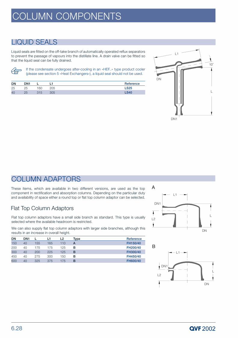
6.28
COLUMN COMPONENTS
LIQUID SEALSLiquid seals are fitted on the off-take branch of automatically operated reflux separatorsto prevent the passage of vapours into the distillate line. A drain valve can be fitted sothat the liquid seal can be fully drained.
ReferenceLS25LS40
DN12525
L160315
L1205305
DN2540
If the condensate undergoes after-cooling in an »HEF..« type product cooler(please see section 5 »Heat Exchangers«), a liquid seal should not be used.
COLUMN ADAPTORSThese items, which are available in two different versions, are used as the topcomponent in rectification and absorption columns. Depending on the particular dutyand availability of space either a round top or flat top column adaptor can be selected.
Flat top column adaptors have a small side branch as standard. This type is usuallyselected where the available headroom is restricted.
We can also supply flat top column adaptors with larger side branches, although thisresults in an increase in overall height.
Flat Top Column Adaptors
ReferenceFH150/40FH200/40FH300/40FH450/40FH600/40
DN14040404040
DN150200300450600
L155175200275325
L1165175225300375
TypeABBBB
L2110125125150175

6.29
COLUMN COMPONENTS
COLUMN ADAPTORS
The side branch on this version provides a large free cross-section, as required forexample to facilitate connection to an external shell and tube condenser (please seesection 5 »Heat Exchangers«) and/or a vacuum pump.
All round top adaptors also have an additional branch that can be used, for example,to insert a measuring probe.
Round Top Column Adaptors
ReferenceCA80/40/25CA100/50/25CA150/50/25CA150/80/25CA200/50/40CA200/80/40CA200/100/40CA200/150/40CA300/50/40CA300/80/40CA300/100/40CA300/150/40CA450/80/50CA450/150/50CA450/200/50CA600/80/50CA600/150/50CA600/200/100CA600/300/100CA800/200/150CA800/300/150CA1000/200/150CA1000/300/200
DN140505080508010015050801001508015020080150200300200300200300
DN22525252540404040404040405050505050100100150150150200
DN8010015015020020020020030030030030045045045060060060060080080010001000
L1802302402553503754254504254754755505756757507508008508501250125013001300
L1110125150165175200225250225250275300325375350400450425500575650675750
TypeAAAABBBBBBBBBBBBBBBBBBB
L290125125125125150175200150175175225200250300300300300400500500500500

6.30
COLUMN COMPONENTS
COLUMN SECTIONS WITH GLASS/PTFE BUBBLE-CAP PLATES
Reference without dip pot
Type BBCS200/1000BCS300/1000BCS450/1500BCS600/1500
Reference with dip pot
Type ABCSA200/1000BCSA300/1000BCSA450/1500BCSA600/1500
L
1000100015001500
DN
200300450600
H
200250300375
Numberof plates
5454
Caps per plate
251324
Down-comers per plate
1122
H1
approx.
91116141179
Technical Data
There are two different versions of columns with bubble cap plates available withborosilicate glass 3.3/PTFE/tantalum bubble-caps or with stainless steel bubble-caps(please see page 6.31). The actual column section is borosilicate glass 3.3 in both cases.
Column sections specifically designed for the purpose are used to provide correctsupport for the plates, to ensure that they are firmly fixed on the underside and to ensurea permanently reliable edge seal. This is achieved by reducing the cross-section of theouter jacket within sufficiently close tolerances at the appropriate points and using aPTFE sealing ring. The glass plates and sealing rings are also braced within the columnby means of tantalum hooks as protection against pressure surges.
The standard bubble-caps supplied have a relatively low pressure drop. These bubble-caps can, however, be supplied with risers on, as these are better suited for use asscrubbers which are downstream of batch processes. This ensures that the scrubbingliquid is retained on the plates when vapour flow is halted for short periods.
Glass pipes are used as downcomers, with a cross-section selected for the liquidloading for the particular application. The bottom column section requires a downcomerfitted with a dip pot to provide a liquid seal. Both versions, i.e. with and without dip pot,can be found in the table below
Further information on column sections with bubble-caps such as areas of application,operating range, flooding point and pressure drop can be found in our special brochure"Column Sections with Random and Structured Packing and Internals”.
Bubblecap slit
H x B16 x 316 x 316 x 316 x 3
DN
200300450600
Free cross-section without riser
(5%)6,47,18,28,5
Free cross-sectionwith riser
(5%)3,94,45,05,2
Weir heightdowncomer
30303030
The normal weir height of the downcomers is 30 mm. If other heights arerequired, please indicate on the order.
If bubble-caps are required with riser, please add »K« to the cataloguereference (for example »BCSAK..«. The relative free cross-section area isreduced to approximately 83 % in this case (please see Technical Data).
Borosilicate glass 3.3 bubble-caps and plates made from other materials canalso be supplied on request.
The end form, which depends on the nominal size, is shown in the diagramon page 6.2. Further information can be found in section 1 »TechnicalInformation«.

6.31
COLUMN COMPONENTS
COLUMN SECTIONS WITH STAINLESS STEEL BUBBLE-CAP PLATES
Reference
CSG80/1000CSG100/1000CSG150/1000
L
100910071010
DN
80100150
H
80111200
Number ofplates
1195
Caps per plate
111
H1
4247109
H2
--145
H3
-4564
H4
6--
There are two different versions of columns with bubble cap plates available: withstainless steel bubble-caps or with borosilicate glass 3.3 bubble-caps (please see page6.30). The actual column section is borosilicate glass 3.3 in both cases.
The stainless steel bubble-cap internals are completely preassembled and thenintegrally fitted into precision bore borosilicate glass 3.3 pipe sections so that theirperformance can be visually monitored at all times. The seal between the bubble-capplates and the pipe section is made with specially designed PTFE seals.
The original version of the bubble-cap design was a single bubble-cap sized to provideoptimum vapour and liquid cross sectional areas. It has now been modified and adaptedto the tube diameters to ensure that the column sections are suitable for high vapourand liquid loading with small tray spacing and ensure a consistently high level ofefficiency over a wide operating range.
To achieve these benefits in their entirety, various designs of bubble-cap have beenselected. In the DN 80 and DN 100 nominal sizes kidney-shaped bubble-caps are usedand circular bubble-caps in DN 150.
Further information on column sections with bubble-caps such as areas of application,operating range, flooding point and pressure drop can be found in our special brochure"Column Sections with Random and Structured Packing and Internals”.
Bubble-cap internals and column sections can also be supplied on request inother materials.

6.32
COLUMN COMPONENTS
PRECISION BORE CYLINDERS
Reference
CCY300/1000CCY450/1000CCY600/1000
Pmax, 20°C(bar)31,51
DN
300450600
D
296 ± 0,5446 ± 0,6590 ± 1,5
L
100010001000
These pipes have no buttress ends and have a very closely toleranced internal diameterover their whole length. They are normally used for chromatography columns and areclamped between two other components.
We would be happy to advise you on suitable design measures.
PRECISION BORE PIPE SECTIONS
D25 ± 0,138 ± 0,150 ± 0,275 ± 0,3100 ± 0,4150 ± 0,4200 ± 0,5296 ± 0,6446 ± 0,7
DN25405080100150200300450
ReferenceCPS25/1000/860CPS40/1000/860CPS50/1000/860CPS80/1000/860CPS100/1000/820CPS150/1000/800CPS200/1000/800CPS300/1000/720CPS450/1000/660
The special feature of these components is their very closely toleranced internal diameterbetween the buttress ends. Together with precision bore cylinders (please see below)they provide a technical and cost-effective solution where column sections are requiredfor special internals such as high efficiency packing and bubble-cap plates with edgeseal or sieve plates without edge seal.
L100010001000100010001000100010001000
L1 860860860860820800800720660
In addition to the standard sizes listed below we can also supply pipe sectionsin other lengths and for higher operating pressures.
The end form, which depends on the nominal size, is shown in the diagramon page 6.2. Further information can be found in section 1 »TechnicalInformation«.
In addition to the standard sizes listed below we can also supply cylinders inother lengths and for higher operating pressures.

6.33
COLUMN COMPONENTS
FILTER PLATES
ReferenceFIL50/...FILN80/...FILN100/...FIL150/...FIL200/...
d70100130185235
DN5080100150200
L2020201619
Porosity0-20-20-20-20-2
190to150
0150to200
240to90
Porosity
Nominal value of the maximum pore diameter (µm)
These porous plates are made of sintered glass powder. They have fused edges andcan be clamped between standard safety buttress ends. They are used to introducegases into columns, for example, in bubble columns, or as filter strainers to separatesolids from liquids (e.g. in precious metal separation units) operating under vacuum.
These filter plates are available in three different porosity ranges. Further information onthis can be found in the table below.
When ordering, please add the code number for the porosity required (pleasesee above) to the catalogue reference.
The permissible pressure difference for all filter plates is 1 bar.

8 MEASUREMENT & CONTROL
PROCESS PLANT COMPONENTSP 308 e.3 Copyright © 2007, QVF Engineering GmbH. All rights reserved.

8.2
MEASUREMENT & CONTROL
GeneralQVF measurement and control equipment complements the component range andensures that borosilicate glass 3.3 plant and apparatus operates safely. In addition tocommercially available equipment, which we always fall back on if it complies with ourcorrosion resistance requirements, we also offer a range of special items (in particulartransducers) developed either by ourselves or in cooperation with well-known companies.
Above all, because of their corrosion resistance, our transducers are widely used in thechemical and pharmaceutical industries and also in a wide range of related areas, aswell as food and drinks manufacturing, dyeing and the electroplating industry. Thespecial properties of borosilicate glass 3.3 and tantalum contribute to this plus the factthat borosilicate glass 3.3 is an approved and tried and tested material for theconstruction of pressure vessels.
The full range of standard equipment is described on the following pages. Reference ismade in the particular product description of special versions that can be supplied onrequest.
In addition to the individual items of equipment we can also supply completecontrol loops, measurement and control systems and process control systemsincluding the necessary documentation and control panels subject to therelevant regulations in each case (e.g. CENELEC).
GMP Compliant InstallationsThe use of transducers and, where required, the layout of interconnecting pipeworkincorporating valves when constructing plant and apparatus complying with GMPguidelines calls for special care in the design and selection of the components used andthe materials of construction employed for them. Because of its special properties thatare so highly valued in the pharmaceutical industry in conjunction with the PTFEmaterials (gaskets, special parts, bellows) approved in accordance with the FDA catalog,borosilicate glass 3.3 guarantees that the build-up of deposits is prevented in areas incontact with the product. The design and arrangement of many transducers results inthe avoidance of any dead space and ensures that they can be fully drained and easilyand effectively cleaned. Appropriate stainless steel coupling and support materials areavailable (please see section 9 "Couplings” and section 10 "Structures”) to ensure thatthe external design of these assemblies meets clean room requirements.
Permissible Operating ConditionsWhile the permissible operating temperature for all borosilicate glass 3.3 componentsis generally 200ºC, the permissible positive operating pressure is dependent on the mainnominal size and not on the shape of the component.
Detailed information on this can be found in section 1 "Technical Information”.

8.3
MEASUREMENT & CONTROL
The installation and operation of electrical equipment in hazardous areas is covered bythe "Regulations for electrical installations in potentially explosive atmospheres ElexV”.
EC Directive 94/9/EC (ATEX 100a)
This directive regulates the suitability of equipment and protective systems intended foruse in potentially explosive atmospheres and lays down fundamental safetyrequirements.
Fundamental Technical PrinciplesClassification of zones Hazardous areas are classified into zones based on the frequencyand duration of the occurrence of explosive atmospheres. Information and guidelineson the classification of zones can be found in IEC 60079-10 and national standards.
In Zones 0 and 1 only electrical equipment may be used for which a certificate ofconformity or a type examination certificate exists; in Zone 0, however, only apparatusspecifically certified for this purpose may be installed. The table below provides anoverview of the classification of zones and indicates the apparatus applicable to theparticular zone.
Dusts are classified in Zones 20, 21 and 22 and correspond to Categories 1D, 2D, 3D(D = Dusts).
PRINCIPLES OF EXPLOSION PROTECTION
Gases, vapours, mists
Zone 0
Zone 1
Zone 2
Category
1 G
2 G
3 G
Potentially explosive atmosphere present(in accordance with 94/9/EC)
Continuously or for long periods or frequently
Occasionally
Rarely or for short periods
Explosion groups
Electrical equipment is differentiated into two groups:
Group I: Electrical equipment for mining.Group II: Electrical equipment for the chemical industry, petrochemical industry, mills, etc.
Temperature classes
The maximum surface temperature of electrical equipment must always be lower thanthe ignition temperature of the gas or vapour/air mixture where it is to be used.Equipment that meets a higher temperature class (e.g. T5) can of course also be usedin applications requiring a lower temperature class (e.g. T2 or T3).
Permissible surface temperature of the electrical equipment
Certification and markingMarking in accordance with EN 50014 [ E Ex ia ] IIC T6
Temperature classExplosion groupIgnition protection type
Additional marking in accordance with EC Directive94/9/EC (ATEX 100a)
T1
450 °C
T2
300 °C
T3
200 °C
T4
135 °C
T5
100 °C
T6
85 °C
EX II (1) G

THERMOMETERS FOR LOCAL DISPLAY
8.4
MEASUREMENT & CONTROL
These are supplied as standard with safety flat buttress end and can be fitted in DN 25nominal size measuring branches. The measuring range is 0 to 200 ºC.
Thermometers for local display are made of 16 III Normalglas. They are mainly used inlaboratories and pilot plants and are available in three different versions. The angledversions are mainly used in column adaptors, spherical vessels and columns. Becauseof the properties of the mechanical sensors severe turbulence should be avoided in themeasuring vessel. The thermometers are filled with light oil (petroleum).
As these thermometers are made from 16 III Normalglas (equivalent to N16Bthermometer glass) it is not possible to make them in DN 40. It is, therefore,necessary to specify a spherical vessel with a DN 25 side branch when usinga THL45/... thermometer.
Our 45º and 90º angled thermometers have a scale that can be rotatedthrough 360° for ease of legibility.
Thermometers with limit contact can be found on page 8.7.
DN25252525
ReferenceTHL100THL150THL200THL300
L100150200300
H265265265265
d15151515
THERMOMETERS FOR LOCAL DISPLAY
Straight Thermometers

8.5
MEASUREMENT & CONTROL
THERMOMETERS FOR LOCAL DISPLAY
THERMOMETERS FOR LOCAL DISPLAY
DN25252525
ReferenceTHL90/100THL90/150THL90/200THL90/300
L100150200300
H265265265265
H1100100100100
d15151515
90° Angled Thermometers
DN
2525252525
Reference
THL45/160THL45/210THL45/300THL45/375THL45/475
L
160210300375475
L1
115125150135155
H
255255255255255
H1
9090909090
d
1515151515
for sphericalvessel (l)
102050100200
45° Angled Thermometers

8.6
MEASUREMENT & CONTROL
REMOTE DIAL THERMOMETERSThese remote-reading dial thermometers are supplied for direct temperaturemeasurement in parts of plant where access is difficult. The display can be mounted inan easily visible place on the support structure by means of a bracket that is includedin the scope of supply and suitable for pipe diameters between 20 and 80 mm. Themeasuring probe is located in a glass protective sheath at the measuring point.
A 3 m long stainless steel flexible capillary is used to connect the display and the sensor.To achieve better heat transfer the tip of the protective sheath is filled with silicone heattransfer paste.
These remote dial thermometers can also be supplied with an inductive max. contact(THLDC..). They then comply with the requirements applicable to Group II electricalequipment for use in category 2G (zone 1) hazardous areas.
On request we also supply these remote dial thermometers for othermeasuring ranges (e.g. 0 – 200 °C) and remote line lengths.
Remote dial thermometers with contact device require the use of anappropriate isolating switching amplifier.
Technical dataDisplay Diameter - 100 mm (nominal size)
Measurement range - 0-120 °C (2 ºC graduations)Measurement accuracy - Class 1 without glass protective
sheatHousing temperature - -20 to +65 °CMeasurement principle - Gas pressure (inert gas filling)Protection type - IP 56
Contact device Version - inductive(Type THLDC) Type of explosion
protection - II 2 G, EEx ia IIC T6Switching function - Max. contact, closing with
increasing temperatureCable connection - Plug with screw connection
Dip tube: Diameter - 10 mmRemote line (capillary) Diameter x length - 2 x 3000 mm
Materials Display - Stainless steelDip tube/remote line - Stainless steelBracket - Steel, galvanised

8.7
MEASUREMENT & CONTROL
REMOTE DIAL THERMOMETERSRemote Dial Thermometer without Contact*
ReferenceTHLD25/100THLD25/150THLD25/200THLD25/300
L100150200300
DN25252525
H105105105105
H219191919
H1430430430430
H350505050
E85858585
D100100100100
d120202020
TypeAAAA
Remote Dial Thermometer with Contact *
*for
ReferenceTHLDC25/100THLDC25/150THLDC25/200THLDC25/300
L100150200300
DN25252525
H105105105105
H219191919
H1430430430430
H3103103103103
H484848484
E85858585
D100100100100
d120202020
TypeBBBB

8.8
MEASUREMENT & CONTROL
RESISTANCE THERMOMETERS FOR CATEGORY 2GHAZARDOUS AREASIf there is a requirement to transfer temperatures to a control room or a process controlsystem, resistance thermometers can be used as transmitters. They comply with therequirements applicable to Group II electrical operating equipment for use in category2G (zone 1) hazardous areas.
The interchangeable measuring sensor used in these resistance thermometerscomprises a stainless steel tube with a Pt 100 built-in four-wire measuring element. Thisis fitted in a virtually universally corrosion resistant borosilicate glass 3.3 protectivesheath with heat transfer paste in the tip. The polyamide head is firmly fixed to the glasspart with adhesive.
The "THRT.." version has a transmitter built into its head and this can be retrofitted inthe "THR..” version or located in the control room. However, in the case of the "THR..”the transmitter is not part of the scope of supply.
Resistance thermometers can be supplied optionally with straight or angled stems (forspherical vessels) and they can be installed in DN 25 and DN 40 nominal size safety flatbuttress ends respectively.
On request we can also supply resistance thermometers with transmitters(Type THRT) for different measurement ranges.
Resistance thermometers for Group II for use in Category 1G (Zone 0)hazardous areas can be found on page 8.10 .
Technical dataMeasuring probe Resistance element - 1x Pt 100 to IEC 751,
Class A, 4-wirePermissible producttemperature - -50 to +200 °C
Head Version - BUKH shapeCable connection - Screw connection, bluePermissible ambienttemperature - -45 to +85 °C
Transmitter Measuring range (built-in, (standard) - 0 to 200 °CType THRT) Output signal - 4 to 20 mA, 2-wire
Type of explosion protection - II 1G EEx ia IIC T6
Materials Thermometer - Stainless steelProtective sheath - Borosilicate glass 3.3Head - Polyamide, black
Type of explosion protection Measuring probe - II 2G EEx ia IIC T6

8.9
MEASUREMENT & CONTROL
RESISTANCE THERMOMETERS FOR CATEGORY 2GHAZARDOUS AREAS
RESISTANCE THERMOMETERS FOR CATEGORY 2GHAZARDOUS AREAS
Straight Thermometers Reference withtransmitter
THRT25/100THRT25/150THRT25/200THRT25/300THRT40/200THRT40/300THRT40/500
Reference without transmitter
THR25/100THR25/150THR25/200THR25/300THR40/200THR40/300THR40/500
L
100150200300200300500
DN
25252525404040
H
183183183183183183183
d
22222222222222
H1
104104104104104104104
45° Angled Thermometers Reference withtransmitter
THRT45/40/160THRT45/40/210THRT45/40/300THRT45/40/375THRT45/50/475
Reference without transmitter
THR45/40/160THR45/40/210THR45/40/300THR45/40/375THR45/50/475
L
160210300375475
DN
4040404050
L1
120130157140170
H1
104104104104104
d
2222222222
for sphericalvessel (l)
10 20 50 100 200
H
183183183183193
8.10
MEASUREMENT & CONTROL
RESISTANCE THERMOMETERS FOR CATEGORY 1G / 2 (1) GHAZARDOUS AREASIf there is a requirement to transfer temperatures to a control room or a process controlsystem, resistance thermometers can be used as transmitters. The THRX rangecomplies with the requirements applicable to Group II electrical operating equipment foruse in category 1G (zone 0) hazardous areas.
These devices consist essentially of a resistance thermometer with stainless steel guardtube, screw-in thread and connection head plus a virtually universally corrosion resistantborosilicate glass 3.3 protective sheath. The two parts are joined together by means ofa connecting piece, the contour of which is the same as a safety flat buttress end, anda standard flange coupling.
A four-wire Pt 100 resistor acts as the measuring element. The measuring tip of theresistance thermometer is inserted in a heat transfer paste.
The "THRXT.." version (Category 2 (1) G) has a transmitter built into its head and thiscan be retrofitted in the "THRX..” version or located in the control room. However, in thiscase the transmitter is not part of the scope of supply.
Resistance thermometers can be installed in measuring branches with DN 25 and DN40 nominal size safety flat buttress ends respectively.
On request we can also supply resistance thermometers with transmitters(Type THRXT) for different measurement ranges.
Thermometers with transmitter type THRXT are only approved for use incategory 2 (zone 1) due to the ex protection type of the transmitter. Yet, theymay be used for a unit in category 1.
Technical data
Measuring probe Resistance element - 1x Pt 100 to IEC 751,Class A, 4-wire
Permissible producttemperature - -50 to +200 °C
Head Version - BUKH shapeCable connection - Screw connection, bluePermissible ambienttemperature - -45 to +85 °C
Transmitter Measuring range (built-in, (standard) - 0 to 200Type THRXT) Output signal - 4 to 20 mA, 2-wire
Type of explosion protection - II 2 (1) G EEx [ia] ib IIC T6
Materials Thermometer - Stainless steelProtective sheath - Borosilicate glass 3.3Head - Polyamide, black
Type of explosion protection Measuring probe - II 1G EEx ia IIC T6

8.11
MEASUREMENT & CONTROL
RESISTANCE THERMOMETERS FOR CATEGORY 1G / 2 (1)GHAZARDOUS AREASResistance Thermometers
Reference withtransmitterCategory 2 (1)G
THRXT25/100THRXT25/150THRXT25/200THRXT25/300THRXT40/200THRXT40/300THRXT40/500
Reference without transmitterCategory 1 G
THRX25/100THRX25/150THRX25/200THRX25/300THRX40/200THRX40/300THRX40/500
L
100150200300200300500
DN
25252525404040
H
275275275275275275275
d
22222222222222
H1
104104104104104104104

8.12
MEASUREMENT & CONTROL
PRESSURE GAUGESThese pressure measurement instruments can be connected to glass branches and withtheir flush laser-welded tantalum diaphragm they guarantee a corrosion-resistant, dead-space-free and GMP compliant arrangement of measuring points. As the contour of thepressure gauge is the same as a pipe section with safety flat buttress end, it can beconnected directly to DN 25 nominal size measuring branches using a standard flangecoupling.
The pressure gauges can be supplied for three measuring ranges and optionally withan inductive max. contact as well. With this contact they then comply with therequirements applicable to Group II electrical operating equipment for use in category2G (zone 1) hazardous zones.
On request we can also supply these pressure gauges with differentmeasurement ranges.
Pressure gauges with contact device require the use of an appropriate isolatingswitching amplifier.
Flange contour also suitable for connection to Schott flange with standardSchott coupling.
For use under vacuum in plants complying with GMP guidelines for the –1 to+1.5 bar measuring range a standard 'O' ring gasket (type TR) should beincluded.
The pressure gauges can be used at temperatures from -50 to +200°C,although the accuracy is limited to the temperature range given in the table.
Technical data
Display Diameter - 100 mm (nominal size)Measurement range - see tableMeasurement accuracy - Class 1Indicator - Microadjustable pointerProtection type - IP 65
Pressure gauge Filled with - Synthetic food oilPermissible temperature range - see instrument dataPermissible positive pressure - 1.3 x upper limit of measuring
range
Contact device Version - inductive(Type PGLC) Type of explosion
protection - II 2G EEx ia IIC T6Switching function - Max. contact, closing with
increasing pressureCable connection - Plug with screw connection
Pressure gauge Basic body - Stainless steelmaterials Diaphragm - Tantalum (laser welded)
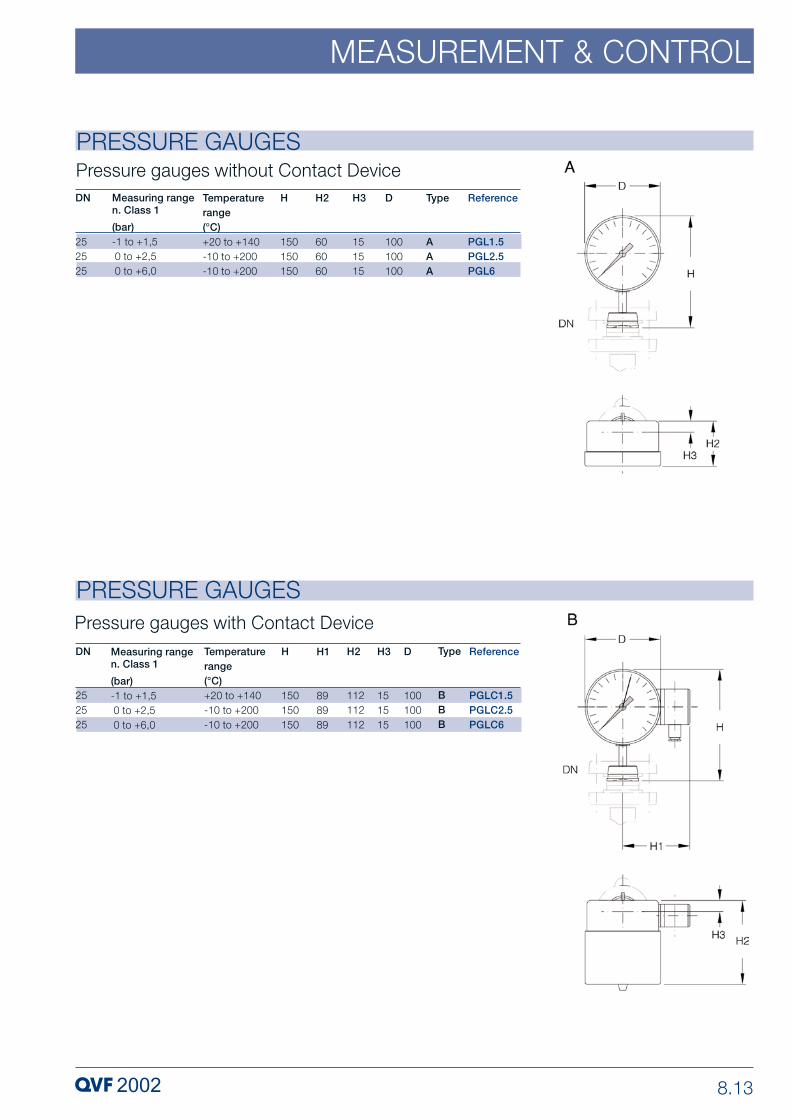
8.13
MEASUREMENT & CONTROL
PRESSURE GAUGES
PRESSURE GAUGES
Reference
PGL1.5PGL2.5PGL6
Measuring rangen. Class 1
(bar)-1 to +1,50 to +2,50 to +6,0
Temperaturerange(°C)+20 to +140-10 to +200-10 to +200
DN
252525
H
150150150
H2
606060
H3
151515
D
100100100
Type
AAA
Pressure gauges without Contact Device
Reference
PGLC1.5PGLC2.5PGLC6
Measuring rangen. Class 1
(bar)-1 to +1,50 to +2,50 to +6,0
Temperaturerange(°C)+20 to +140-10 to +200-10 to +200
DN
252525
H
150150150
H1
898989
H2
112112112
H3
151515
D
100100100
Type
BBB
Pressure gauges with Contact Device

8.14
MEASUREMENT & CONTROL
PRESSURE TRANSMITTERSIf there is a requirement to transfer pressure data to a control room or a process controlsystem, these devices can be used as transducers. The attached pressure gauge withits flush laser-welded tantalum diaphragm guarantees a corrosion-resistant, dead-space-free and GMP compliant arrangement of measuring points. As the contour of thepressure gauge is the same as a pipe section with safety flat buttress end, it can beconnected direct to DN 25 nominal size measuring branches using a standard flangecoupling.
These pressure transmitters comply with the requirements applicable to Group IIelectrical operating equipment for use in Category 1G (zone 0) hazardous areas.
On request we can also supply these pressure transmitters with differentmeasurement ranges.
For use of plants complying with GMP guidelines under vacuum a standard'O' ring gasket (type TR) should be included.
Flange contour also suitable for connection to Schott flange with standardSchott coupling.
Technical data
Pressure transmitter Measurement ranges - See tableMeasurement accuracy - < ± 0.2% of final value at 20 °CZero point error - 4.8 mbar/10 KOutput signal - 4 to 20 mA, 2-wire,
HART optionalOperated by - Graphic display German/English
Protection type - IP 65
Pressure gauge Filled with - VacuumoilPermissible temperature range - -40 to +200 °COverload limit - 6/10 bar abs.
Pressure gauge Basic body - Stainless steelmaterials Diaphragm - Tantalum (laser welded)
Type of explosion protection - II 1/2G EEx ia IIC T6
Reference
PGT4000
Measuring range(mbar abs)0 to 4000
DN
25
H
245
H2
62
H3
119
H1
63

8.15
MEASUREMENT & CONTROL
THERMOMETER POCKETS WITH SCREW CAP
DN252525254040404040
L100150200300200300500650850
L1----150150150150150
H105105105105115115115115115
d202020202828282828
d1161616161616161616
d2101010101010101010
d3----2020202020
ReferenceTPG25/100TPG25/150TPG25/200TPG25/300TPG40/200TPG40/300TPG40/500TPG40/650TPG40/850
These thermometer pockets are designed for use with stem type thermometers or othertemperature probes. Improved heat transfer can be achieved by filling the pocket witha contact fluid or heat transfer paste.
TypeAAAABBBBB

8.16
MEASUREMENT & CONTROL
FLOWMETERSThese devices use a float to determine the volume of liquid or gas flowing through. Theyconsist of a calibrated measuring tube made of borosilicate glass 3.3 with an etchedscale (graduated in mm), the PTFE float and upper and lower PTFE float traps. Alsoincluded in the scope of supply is a calibrated scale clamped to the measuring tube andcalibrated to water (at 20 ºC).. Details of the measuring ranges can be found in the tableon page 8.17.
To ensure accurate measurement, flowmeters must be fitted in an absolutely verticalposition and in DN 80 and above a 5xDN calming zone must be provided before thedevice. Measurement accuracy conforms to Class 1.6.
Operating temperature: -50 to +150°C.
Other calibrated scales can be supplied if required for special liquids/gasesand operating conditions. In such cases the following information shouldbe specified:
– Liquid/gas– Measuring range in l/h or Nm3/h– Density in kg/l or kg/Nm3
– Viscosity in mPa·s– Operating temperature in ºC– Operating pressure in bars– Nominal size of the pipeline
In the case of repeat orders we need the catalogue reference of the flowmeterand the serial number of the etched scale.

8.17
MEASUREMENT & CONTROL
FLOWMETERS
Reference
FML25/4FML25/10FML25/40FML25/63FML25/160FML25/400FML40/630FML40/1000FML50/630FML50/1000FML80/1600FML80/2500FML80/4000FML80/6300
Water (l/h)20°C0,2 – 40,5 – 102 – 404 – 6315 – 16040 – 40060 – 630100 – 100060 – 630100 – 1000160 – 1600250 – 2500400 – 4000630 – 6300
DN
2525252525254040505080808080
Air (m3/h) *1bar abs, 20°C0,010 – 0,180,020 – 0,40,1 – 1,60,2 – 2,40,6 – 6,31,6 – 162,5 – 254 – 402,5 – 254 – 406,3 – 6310 – 10016 – 16025 – 250
L
350350350350350350350350350350350350350350
* Valveas given for air serve as orientation guide and require a special scale.

8.18
MEASUREMENT & CONTROL
FLOWMETERS WITH ELECTRICAL OUTPUTThese devices use a float to determine the volume of liquid or gas flowing through. Theyconsist of a transducer with local display, an attached calibrated measuring tube madeof borosilicate glass 3.3, a PTFE-sheathed float fitted with a magnet, and upper andlower PTFE float traps. The 350 mm long measuring tubes have safety flat buttress endsat both ends. Details of the measuring ranges can be found in the table below.
The position of the float is determined by magnetic sensors and this information isconverted into an electrical output signal.
To ensure accurate measurement, flowmeters must be fitted in an absolutely verticalposition and in DN 80 and above a 5xDN calming zone must be provided before thedevice. Measurement accuracy will then conform to Class 2.5.
On request we can supply these devices with up to two inductive limit switchesprogrammable from the scale suitable for II 2G EEx ia IIC T6 hazardous area protectionfor max. or min. signalling as the case may be. These can also be retrofitted.
The device is also fitted with a LCD display from which the flow rate at the particulartime or the cumulative flow quantity (switchable) can be read off digitally.
Technical data
Display Dimensions - Ø161 mmDisplay range - l/h and m3/h respectivelyDigital display - 8-digit, 7-segment, LCDMeasurement accuracy - Class 2.5Display scale - Flow units l/h and m3/h respectively
Standard: Water 20 °CProtection type - IP 67
Measuring tube Version: - Conical glass tubePermissible operating temperature - -50 to +130 °C
Transducer Measurement range - See tableOutput signal - 4 to 20 mA, 2-wireType of explosion protection - II 2G EEx ia IIC T6Ambient temperature - -25 to +70 °CCable thread - M16 x 1.5
Materials Measuring tube - Borosilicate glass 3.3Measuring tube internals - PTFE and PTFE-sheathed
respectivelyTransducer casing - Stainless steel
Type of explosion protection - II 2G EEx ia IIC T6
If to be designed for liquids or gases other than water or air the followinginformation should be specified:
– Liquid/gas– Measuring range in l/h or m3/h– Density in kg/l or kg/m3
– Viscosity in mPa·s– Operating temperature in ºC– Operating pressure in bars– Nominal size of the pipeline
In the case of repeat orders or changes to the product data we need thecatalogue reference and the serial number of the flowmeter.

8.19
MEASUREMENT & CONTROL
FLOWMETERS WITH ELECTRICAL OUTPUTReference
FMT25/160FMT25/250FMT25/400FMT25/630FMT25/1000FMT40/1600FMT40/2500FMT50/1600FMT50/2500FMT80/4000FMT80/6300FMT80/10000FMT80/16000
Water (l/h)20°C16 – 16025 – 25040 – 40063 – 630100 – 1000160 – 1600250 – 2500160 – 1600250 – 2500400 – 4000630 – 63001000 – 100001600 – 16000
DN
25252525254040505080808080
Air (m3/h)1bar abs, 20°C0,5 – 50,85 – 8,51,3 – 132 – 203,4 – 345 – 508,5 – 855 – 508,5 – 8513 – 13020 – 20035 – 350–
L
350350350350350350350350350350350350350
D
161161161161161161161161161161161161161
H
129129129129129136136136136151151151151
H1
11111111111111111111111111

8.20
MEASUREMENT & CONTROL
ELECTRIC LEVEL CONTROL
Wiring diagram
This comprises a DN 25 nominal size bypass tube, in which a glass float with a built-inmagnet moves up and down, and an externally fitted bistable max. and min. contactwhich is set or reset when the float passes it completely.
The standard scope of supply includes the borosilicate glass 3.3 float, two cast limitswitches (function: max. and min. closing with reference to the up and down travel ofthe float) with pipe supports and two PTFE float traps. These limit the movement of thefloat to the range being monitored. Further limit switches (see below) can be used forextra signalling of alarm situations. A DN 25 bypass tube of the length required shouldbe ordered separately.
The limit switches must be fitted with a contact protection relay or an isolatingswitching device with a II 2G EEx ia IIC T6 input.
ReferenceLEC25
DN25

8.21
MEASUREMENT & CONTROL
ReferenceLEC25-2LEC25-3
H6060
DN2525
H16363
H23030
FunctionMax. closeMin. close
ELECTRIC LEVEL CONTROL
Limit Switches for Level ControlThe standard switches used with the type "LEC…” level controls are the closing type.They store the particular switching point and remain closed until the float passes themin the opposite direction.
Magnetic Float for Level ControlThe magnetic floats used in the type "LEC…” level controls are suitable for use withliquids having a density between 0.8 and 1.2 kg/dm3. On request, however, we can alsosupply these floats for lower densities.
The "DN” figure in the table below refers in all cases to the nominal size of thebypass tube.
Float traps to suit these floats (see below) should be ordered separately.
The switches are supplied with the pipe clamps required.
ReferenceLEC25-1
DN25
L238
d22
ReferenceLEC25-4
L15,5
DN25
n x d13 x 6
Float Traps for Level ControlThe float traps listed here are used with type "LEC…” level controls. They are fitted aboveand below the magnetic float in one of the couplings used with the bypass tube. Theyhave a built-in bead on both sides for sealing purposes and, therefore, there is no needfor a separate gasket.
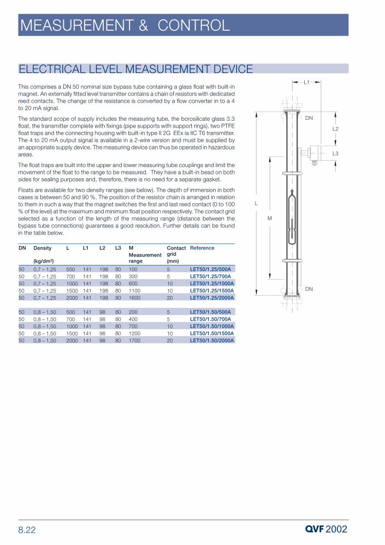
8.22
MEASUREMENT & CONTROL
This comprises a DN 50 nominal size bypass tube containing a glass float with built-inmagnet. An externally fitted level transmitter contains a chain of resistors with dedicatedreed contacts. The change of the resistance is converted by a flow converter in to a 4to 20 mA signal.
The standard scope of supply includes the measuring tube, the borosilicate glass 3.3float, the transmitter complete with fixings (pipe supports with support rings), two PTFEfloat traps and the connecting housing with built-in type II 2G EEx ia IIC T6 transmitter.The 4 to 20 mA output signal is available in a 2-wire version and must be supplied byan appropriate supply device. The measuring device can thus be operated in hazardousareas.
The float traps are built into the upper and lower measuring tube couplings and limit themovement of the float to the range to be measured. They have a built-in bead on bothsides for sealing purposes and, therefore, there is no need for a separate gasket.
Floats are available for two density ranges (see below). The depth of immersion in bothcases is between 50 and 90 %. The position of the resistor chain is arranged in relationto them in such a way that the magnet switches the first and last reed contact (0 to 100% of the level) at the maximum and minimum float position respectively. The contact gridselected as a function of the length of the measuring range (distance between thebypass tube connections) guarantees a good resolution. Further details can be foundin the table below.
ELECTRICAL LEVEL MEASUREMENT DEVICE
DN
5050505050
5050505050
Reference
LET50/1.25/500ALET50/1.25/700ALET50/1.25/1000ALET50/1.25/1500ALET50/1.25/2000A
LET50/1.50/500ALET50/1.50/700ALET50/1.50/1000ALET50/1.50/1500ALET50/1.50/2000A
L
500700100015002000
500700100015002000
L1
141141141141141
141141141141141
L3
8080808080
8080808080
L2
198198198198198
9898989898
MMeasurementrange
10030060011001600
20040070012001700
Contactgrid(mm)
55101020
55101020
Density
(kg/dm3)
0,7 – 1,250,7 – 1,250,7 – 1,250,7 – 1,250,7 – 1,25
0,8 – 1,500,8 – 1,500,8 – 1,500,8 – 1,500,8 – 1,50

8.23
MEASUREMENT & CONTROL
ELECTRICAL LEVEL MEASUREMENT DEVICE
ELECTRICAL LEVEL MEASUREMENT DEVICE
DN
5050
Reference
LET50/1.25-2LET50/1.50-2
Density(kg/dm3)0,7 – 1,250,8 – 1,50
L4
400300
d
4646
Magnetic Float for Electrical Level Measurement Device
DN50
ReferenceLET50/1.25-3
L58
n x d13x10
Float Traps for Electrical Level Measurement Device
On request we can also supply floats for type "LET…” level measurement devices forother density ranges. Float traps to suit these (see below) should be ordered separately.
The float traps for the type "LET..." level measurement device are fitted above and belowthe magnetic float in the measuring tube coupling. They have a built-in bead on bothsides for sealing purposes and, therefore, there is no need for a separate gasket.
The "DN” figure in the table below refers to the nominal size of the bypass tube.

8.24
MEASUREMENT & CONTROL
MAGNET FOR REFLUX SEPARATORSThese ‘U’ magnets are used with Type RHM reflux separators. Used in conjunction withan electrical timer module a movable funnel with an iron core sealed into the glasslocated inside the column can be operated from outside.
Technical data
Supply DC voltage - 24 VDC +6 / -10 %Nominal current - 0.622 AConnecting cable - 3x1.5 mm2, 1.5 m long Max. permissibleambient temperature - -5 to+40 °C
Materials Housing - Aluminium, varnishedMoulding - Polyurethane-based
Protection type Housing - IP 54Explosion protection - II 2 G EEx m II T4
ReferenceRSM80RSM100RSM150
DN80100150
H175192218
H29090100
H1200234239
H3120120157

8.25
MEASUREMENT & CONTROL
ReferenceTMM01TMX01
H72145
D-140
H1135244
TypeAB
ELECTRIC TIMERThis is an electronic timer used for controlling the reflux ratio in rectification columns withelectromagnetically or pneumatically operated reflux separators with magnetic controlvalves. The reflux and offtake times can be adjusted on the timer from 1 to 99 seconds.The boiling point is monitored with a resistance thermometer (Pt 100) and this intervenesin the control so that when a preset temperature is reached the timer switches to totalreflux or offtake and gives a warning that this has happened by sounding an alarm. Whena second cut-off value (hysteresis value from 1 to 9 seconds presettable) is reached, thecontrol returns to the preset timing cycle. There are 4 keys on the front panel which areused to enter all the preset values. Additionally there are 3 different programs available:
Program 0: all functions operating,Program 1: alarm off, fault warning offProgram 2: Pt100 off, output signal off, fault warning off
Timer Module for Rack Mounting
The control unit described above is supplied as timer module type TMM01 for rackmounting.
Timer for hazardous areas, Category 2G
For use in hazardous areas the timer module type TMM01 is built into an EEx de (ia) IICpressure resistant housing and can thus be used as a type TMX01 Group II, Category2G hazardous area timer.
Technical data
Input Pt 100 - 1x Pt 100, 3 to 4 wirePower supply - 24 VDC, 5A
Output Analog signal - 4-20 mATime - Transistor 24 VDC max. 3ACut-off value 1 - Relay max. 40 VDC, 800 mACut-off value 2 - Relay max. 40 VDC, 800 mA
Materials Housing TMM01 - MakrolonHousing TMX01 - Light metal
Protection type Housing TMR01 - IP 50 (Front)Housing TMX01 - IP 65

8.26
MEASUREMENT & CONTROL
ELECTRODESFOR PH, REDOX AND CONDUCTIVITY MEASUREMENT
The TMXP controller is a pneumatic timer used for controlling pneumatic refluxseparators. As it operates completely pneumatically, it can be used without restrictionin hazardous areas. The reflux and offtake times can be adjusted on the timer from 0.3to 10 seconds or alternatively from 0.3 to 100 seconds. There are two buttons whichcan be used, when the timer is set to "Manual”, to switch it to total offtake or total reflux.When set to "Automatic” the timer starts the preset reflux ratio. Whether set to "Manual”or "Automatic” the instrument display panel indicates the current position of the refluxseparator (reflux or offtake).
The equipment available for process monitoring and control of pH, Redox andconductivity includes borosilicate glass electrode measuring chambers with PTFEflange. Up to two commercially available electrodes with PG 13.5 thread and 120 mmlong can be fitted in the PTFE flange. One screw thread is blanked off as standard. Themaximum operating temperature is 120 °C. The choice of a suitable electrode isgoverned by the process conditions.
If glass electrodes cannot be used for conductivity measurement, we can alsosupply inductive measuring cells for the measuring chamber.
Straight and angled dip tubes can be supplied in various lengths for use incolumns, receivers and spherical vessels.
PNEUMATIC TIMER
ReferenceTMXP
H300
H2210
H1380
E420
d12
Electrode Measuring ChambersReferenceQIP25
DN25
DN215
DN140
L200
L183
D105
H98

8.27
MEASUREMENT & CONTROL
ELECTRODESFOR PH, REDOX AND CONDUCTIVITY MEASUREMENT
Straight Dip Tubes
Angled Dip Tubes for Installation in Spherical Vessels
ReferenceQID40/500QID40/650QID40/850
DN404040
L500650850
D373737
H128128128
ReferenceQID45/40/275QID45/40/350QID45/50/450
DN404050
L275350450
L1150150150
D373737
for spherical vessel (l)50 100 200
H128128138
Straight and angled probes are suitable for process monitoring in columns and vessels.The dip tubes are made of borosilicate glass 3.3 and include a PTFE assembly, in whicha standard electrode with PG 13.5 thread and 120 mm length may be fitted. The sealbetween glass and PTFEassembly is made of viton.
The maximum operating temperature is 120°C.

8.28
MEASUREMENT & CONTROL
ELECTRICAL INTERFACE MEASUREMENTFloat type measuring instruments are used for interface measurement in extractioncolumns. The float’s magnet system activates a resistor chain in the guide tube whichcorresponds to a 3-wire potentiometer circuit. A 2-wire measurement transformer in theconnection housing converts the resistor chain signal with a 5 mm contact grid to 4-20 mA.
These floats can only be installed from above in a branch with a minimum size of DN 80.The density of the heavy phase must be at least 0.70 kg/dm3.
Technical data
Supply Control voltage - 24VDC 2-wireOutput signal - 4-20 mAAmbient temperature - max. 70 °C
Materials Connection housing - AluminiumFlange - Stainless steelWetted - Stainless steel
Protection type Housing - IP 65Explosion protection - II 2 G EEx ib IIC T6

8.29
MEASUREMENT & CONTROL
PNEUMATIC INTERFACE MEASUREMENTFloat type measuring instruments are used for measuring the interface between twoliquids in horizontal separators and extraction columns. The measurement signal isconverted by means of magnetic transmission from a pneumatic proportional controllerinto a 0.2 to 1 bar output signal. These floats can be installed either from the side or fromabove in a branch with a minimum size of DN 80. The output signal at the float’s midpointis 0.6 bar. The normal control range is +15mm/-15mm and this can be extended bylengthening the stem. The density of the heavy phase must be at least 0.70 kg/dm3.
If the output signal is not switched directly to a pneumatic control valve, the signal canbe converted via a P/I converter (option) to 4-20 mA and processed in an electricalcontroller.
Technical data
Supply Instrument air - 1.4 barControl connection - G 1/8Ambient temperature - 0 to +80 °C
Materials Connection housing - Aluminium die castingWetted - Stainless steel or PTFE
Protection type Housing - IP 65

9 COUPLINGS
PROCESS PLANT COMPONENTS
P 309 e.3 Copyright © 2007, QVF Engineering GmbH. All rights reserved.

9.2
COUPLINGS
IntroductionQVF couplings are a strong and high-duty system providing maximum reliability with theminimum of maintenance. This is achieved throughout the whole range of nominal sizesby the use of the safety buttress end, which has been designed specifically to take intoaccount the properties of the material, coupled with corrosion resistant, easy-to-installgaskets plus the carefully dimensioned individual parts of the actual coupling. Thematerials are selected to consider both the type of products being handled in the plantand equipment and also the possibility that they may be located in a corrosiveatmosphere.
The particular properties of borosilicate glass 3.3 and the fact that it is an approved andproven material of construction for pressure vessels are of prime importance in thisconnection. This is one of the reasons that borosilicate glass 3.3 is so widely used inthe chemical, pharmaceutical and allied industries together with other applications suchas food and drink production, dye works and electroplating.
The complete range of standard components available is described on the followingpages. Non-standard components can, however, also be supplied to special order.
A detailed listing of all couplings and individual components by »Description« and»Catalogue Reference« can be found in the »Index«.
Detailed information on couplings and a number of other topics referred to inthe following pages can be found in Section 1 »Technical Information«.
The use of flexible gaskets (please see page 9.24) makes it possible to achievea deviation of up to 3º and provides the same degree of movement as a balland socket system.
The term »DN« always refers in this section to the nominal size of the glasscomponents.
GMP and clean room compliant installationsThe design of plant and equipment complying with GMP regulations calls for special carein both the planning and selection of the components together with the materials ofconstruction used for them. Borosilicate glass 3.3 has a number of special propertiesthat are highly valued in the pharmaceutical industry, and these, in conjunction with PTFEmaterials (gaskets, bellows, lining) approved in accordance with the FDA catalogueensure that any build-up of unwanted deposits is avoided in areas which come in contactwith the product. A design without any dead space, which ensures that componentsdrain fully and can be cleaned easily and effectively, is achieved in the case of manycomponents by their shape and the way they are installed.
All these benefits can, however, only be taken advantage of if the gaskets used meetthe same criteria. For that reason we use exclusively gaskets made from PTFE of thehighest quality and can also supply a special GMP compliant gasket without any deadspace (please see page 9.23) in addition to the other types of gasket available.
Where the external surfaces of the pipeline have to comply with clean roomrequirements, appropriate stainless steel coupling and support material can be supplied(please see also Section 10 »Structures and Supports«).
We would be happy to advise you on the basis of the regulatory requirements applicableto a particular case and the guidelines drawn up by us for the design of GMP compliantplant and for plant suitable for use under clean room conditions.
9.3
COUPLINGS
Sealing In Accordance With TA LuftThe former German regulation "Technical Manual for Clean Air" (TA Luft) was amended,and the updated version came into force on 2004-07-24. It contains maximumpermissible limiting values for dust, steam, or gas emissions during the processing,conveying, or re-filling of dust, fluid, or gas materials.
TA Luft requires that flange connections conform to a specific leaking rate of10-5 kPa.l /(s.m). Compliance shall be proven by a design inspection in accordance withVDI 2440 (edition November 2000).
QVF flange connections have undergone design category inspections by TUEVRhineland / Berlin-Brandenburg, and fulfill the specified requirements.
The relevant certificates may be supplied upon demand.
Coated glass componentsDamage to borosilicate glass 3.3 components resulting from accidental external causescannot be entirely excluded, especially in the smaller nominal sizes. This isprimarily dueto the relatively rigorous conditions prevalent in production plants and applies especiallywhere no additional protection is provided in the form of insulation.
Standard couplings and inserts are used to install Sectrans coated borosilicate glass3.3 components.
In the case of components with a glass fibre reinforced polyester coating, which providesa higher level of protection, and can also be supplied on request, couplings completewith thinner inserts are required for nominal sizes DN 15 to DN 150.
Permissible operating conditionsAll couplings are suitable for operating temperatures of up to 200 ºC on the product side and for the permissible operating pressure applicable to the particular nominal size.Plastic flanges may, however, only be used up to an operating temperature of 150 ºCon the product side when lagged.
In the case of cover plate assemblies, quick release couplings and bellows,the operating conditions indicated in the respective product description apply.
Connection to other materialsThe requirement for connecting QVF borosilicate glass 3.3 plant and equipment to othermaterials of construction such as PTFE lined components, glass-lined branches andexotic materials, to mention but a few, is becoming more and more frequent
In addition to standard couplings for glass components, the following pages also containsolutions for these very different applications. They ensure that the normal bolting forcesapplicable to glass plant are applied but without being exceeded.

9.4
COUPLINGS
Various types of couplings are available to join borosilicate glass 3.3 componentstogether to install operable pipelines and process plants. They are designed to complynot only with the requirements of GMP-compliant installations but also consider the factthat glass plant and pipeline often has to operate in relatively corrosive environments.
The table below provides a summary of the various couplings available:
Coupling
For uncoated andSectrans coatedcomponents
Version 1
Version 2
For glass fibre reinforced polyester coated components
Version 1
Version 2
For uncoated and Sectrans coated components and flexible gasket
Version 1
Version 2
For glass fibre reinforced polyester coated components and flexible gasket
Version 1
Version 2
For fixed points
Version 1
Version 2
COUPLINGS
15 25 40 50 80 100 150 200 300 450 600 800 1000Nominal size
Plastic, »CP..« type
Cast iron/Steel, »CCS..« type
Cast iron/Steel, »CCS..« type
Stainless steel, »CCS..« type
Plastic, »CP..« type
Stainless steel, »CCS..« type
Steel, »CCSF..« type
Stainless steel, »CSSF..« type
Stainless steel, »CSS..« type
Plastic, »CP..C« type
Stainless steel, »CSS..C« type
Plastic, »CP..G« type
Stainless steel, »CSS..G« type
Plastic, »CP..GC« type
Stainless steel, »CSS..GC« type

9.5
COUPLINGS
COUPLINGSComplete couplings include two flanges and two inserts in the selected materials andthe necessary quantity of stainless steel nuts, set screws, flat washers and springs. Adetailed description of all the individual parts can be found on pages 9.12 to 9.20.
Compression springs are used to set and maintain the correct bolt load on the coupling.Further information on this can be found under the Compression Springs heading onpage 9.20.
We recommend greasing stainless steel coupling set screws as protection againstseizure.
Couplings do not include gaskets which should be ordered separately andshould be selected in accordance with the operating requirements of eachparticular case (please see page 9.22 to 9.24).
Standard inserts can be used with Sectrans coated glass components (suffix»L«) but glass fibre reinforced polyester coated components (suffix »C«) in theDN 15 to DN 150 nominal size range require the use of thinner inserts (pleasesee section 1 »Technical information« and page 9.4).
In the DN 15 to DN 600 nominal size range fixed points are created by usinga combination of standard couplings and support frames (type A) or supportplates and support frames (type B) respectively in the structure. For nominalbore DN 450 use the special drilled flanges CCS450RRD or CSS450RRD. Inthe DN 800 and DN 1000 nominal size a special fixed point coupling (type C)is required. This includes a fixed point flange which is fixed directly to the heavyduty support stool.
»RRD..« tubular support frames and »UBD..« profile steel support frames canbe found in section 10 »Structures & Supports«. Examples are illustratedalongside.

9.6
COUPLINGS
COUPLINGS
The standard version of these couplings incorporate glass fibre reinforced Duroplastflanges with inserts in plastic (up to DN 150 nominal size) or Duroplast with rubber/glassfibre layer in DN 200 and DN 300 respectively plus nuts, set screws, flat washers andsprings.
These couplings do not require earthing, even if the products being handled are proneto set up an electrostatic charge as all the metal parts (set screws etc.) have a sufficientlylow capacitance.
In addition, we supply couplings in the DN 15 to DN 150 nominal size range with thinnerinserts as required for use with glass fibre reinforced polyester coated glass components(please see table on page 9.4) or, if applicable, longer set screws for use with flexiblegaskets (please see page 9.24). These different versions are identified by adding theappropriate suffix to the catalogue reference.
DN1525405080100150200300
ReferenceCP15CP25CP40CP50CP80CP100CP150CP200CP300
If thinner inserts are required for glass fibre reinforced polyester coated glasscomponents of nominal sizes DN 15 to DN 150, the suffix »C« should be addedto the catalogue reference which then becomes, for example, »CP..C«.
In nominal sizes DN 200 and DN 300 the standard couplings can also be usedwith Sectrans and glass fibre reinforced polyester coated glass components.
When flexible gaskets are used, longer set screws are necessary and a»G«should be added to the catalogue reference which then becomes, for example,»CP..G«.
Catalogue references with the suffix »GC«, e.g. »CP.. GC«, refer to couplingsfor use with flexible gaskets in combination with coated glass components.
D7090109122160204280321428
K50708698133178254295400
n x d13 x M63 x M83 x M83 x M86 x M86 x M86 x M108 x M812 x M8
H396166738798100112113
TypeAAAAAAABB
Couplings with Plastic Flanges

9.7
COUPLINGS
COUPLINGS
These couplings incorporate epoxy resin painted spheroidal graphite cast iron flanges(DN 450 and DN 600) or welded steel flanges (DN 800 and DN 1000) respectively,bonded rubber/glass fibre inserts plus stainless steel set screws, nuts, flat washers andsprings. They can also be used with Sectrans and glass fibre reinforced polyester coatedglass components.
DN4506008001000
ReferenceCCS450CCS600CCS800CCS1000
D6157559961170
K5857109501120
n x d116 x M820 x M1224 x M1228 x M12
H146173121123
H1--253255
TypeAABB
Couplings with Cast Iron and Steel Flanges

9.8
COUPLINGS
COUPLINGSCouplings with Stainless Steel FlangesThe standard version of these couplings incorporate stainless steel flanges, set screws,nuts, flat washers and springs. The inserts are plastic (up to DN 150 nominal size),Duroplast made of rubber/glass fiber support surfaces (in DN 200 and DN 300) orrubber/glass fibre in DN 450 and above respectively.
In addition, we supply couplings in the DN 15 to DN 150 nominal size range with thinnerinserts as required for use with glass fibre reinforced polyester coated glasscomponents (please see table on page 9.4) or longer set screws for use with flexiblegaskets respectively (please see page 9.24). These different versions are identified byadding the appropriate suffix to the catalogue reference.
If thinner inserts are required for glass fibre reinforced polyester coated glasscomponents of nominal sizes DN 15 to DN 150, the suffix »C« should be addedto the catalogue reference which then becomes, for example, »CSS..C«.
In nominal sizes DN 200 to DN1000 the standard couplings can also be usedwith Sectrans and glass fibre reinforced polyester coated glass components.
When flexible gaskets are used, longer set screws are necessary and a »G«should be added to the catalogue reference which then becomes, for example,»CSS..G«.
Catalogue references with the suffix »GC«, e.g. »CSS GC«, refer to couplingsfor use with flexible gaskets in combination with coated glass components.
DN15254050801001502003004506008001000
ReferenceCSS15CSS25CSS40CSS50CSS80CSS100CSS150CSS200CSS300CSS450CSS600CSS800CSS1000
D64851061241552002843254286157559961170
K507086981331782542954005857109501120
n x d13 x M63 x M83 x M83 x M86 x M86 x M86 x M108 x M812 x M816 x M820 x M1224 x M1228 x M12
H385966728395979697116125121123
H1-----------253255
TypeAAAAAAABBCCDD
K
D
d1
H
DNA

9.9
COUPLINGS
COUPLINGS FOR DURAPACK® COLUMNSAs described in section 6 »Column Components«, structured packing and, alsoDURAPACK® high efficiency packing is supported on a support ring. These aredesigned to be clamped in a coupling and for this purpose longer set screws arerequired. The complete couplings described on the following page take this aspect intoaccount.
As regards design and the materials used they are the same as the »CP..« and »CCS..«couplings or alternatively »CCSF..« (fixed point coupling) which are described in detailon pages 9.6, 9.7 and 9.10. For this reason only two (»CPDU..« and »CCSFDU..«) ofthe versions actually available are shown.
These couplings can also be supplied on request with stainless steel flanges.
ReferenceStainless steel
CSSF800CSSF1000
ReferenceSteel
CCSF800CCSF1000
n x d1
24 x M1228 x M12
DN
8001000
D
9961170
K
9501120
K1
10501220
In DN 800 and DN 1000, fixed points are created by using special couplings on a profilesteel support frame. They incorporate one standard and one fixed point flange whichis fixed directly to the U-profile frame by means of four support lugs set at 90°.
n x d2
4 x 184 x 18
H
121123
H1
298300
H2
187188
COUPLINGSSteel and Stainless Steel Fixed Point Couplings
For the nominal diameter DN 450, fixed-point connections are implementedvia special flanges CCS450RRD and CSS450RRD in connection with asupport frame.

9.10
COUPLINGS
COUPLINGS FOR DURAPACK® COLUMNS
COUPLINGS FOR DURAPACK® COLUMNS
Couplings for Column Sections
Fixed Point Couplings
DN1001502003004506008001000
ReferenceCPDU100CPDU150CPDU200CPDU300CCSDU450CCSDU600CCSDU800CCSDU1000
D2042803214286157559861160
K1782542954005857109501120
H105109122128164191139141
n x d16 x M86 x M108 x M812x M816 x M820 x M1224 x M1228 x M12
DN8001000
ReferenceCCSFDU800CCSFDU1000
D9961170
K9501120
K110501220
H139141
H2183184
H1313315
n x d124 x M1228 x M12
n x d24 x M184 x M18

9.11
COUPLINGS
There is a frequent requirement in process plant applications to open or close couplingsas quickly as possible without using tools. Charging materials to reaction or extractionvessels or replacing measurement indicators are typical examples of this. The idealsolution in such instances is our quick release couplings.
These comprise a stainless steel upper flange with slotted bolt holes, hinged quickrelease bolts and a lower plastic backing flange which is fixed to prevent it falling down.The support ring and the fastenings are stainless steel. As with all couplings, the gasketis not included and should be ordered separately.
QUICK RELEASE COUPLINGS
The permissible operating pressure for quick release couplings ranges from -1 to +0.5 bar g as the bolts can only be tightened by hand.
If thinner inserts are required for glass fibre reinforced polyester coated glasscomponents of nominal sizes DN 25 to DN 150 (please see page 9.4), thesuffix »C« should be added to the catalogue reference which then becomes»CVS..C«.
In nominal sizes DN 200 and DN 300 the standard couplings can also be usedwith Sectrans and glass fibre reinforced polyester coated glass components.
DN25405080100150200300
ReferenceCVS25CVS40CVS50CVS80CVS100CVS150CVS200CVS300
D90109122160204280321428
K708698133178254295400
n x d13 x M83 x M83 x M86 x M86 x M86 x M108 x M812 x M8
TypeAAAAAABB
These shackle closures provide a more convenient solution for special applicationscompared to the quick release couplings described previously. They have a swivellingbracket and are closed or released by means of a spindle attached to it via a centrallylocated hand-wheel.
The flange, cover, bracket and hinged bolts are stainless steel. The cover is faced witha PTFE disc on the product side and the O-ring which is also corrosion resistant, islocated in a recessed groove so that it cannot fall out when the closure is opened.
SHACKLE CLOSURES
The permissible operating overpressure of the shackle closure is -1 to +0.1 bar. Theversion KMC...A may be deployed at an operating overpressure of +0.6 bar, if theunit is equipped with a local pressure gange.
If thinner inserts are required for glass fibre reinforced polyester coated glasscomponents, the suffix »C« should be added to the catalogue reference whichthen becomes »KMC..C«.
DN5080100150
Reference-1/+0,1 barKMC50KMC80KMC100KMC150
D132155200280
d1M8M8M8M10
K110133178254
H138148178180
Reference-1/+0,6 barKMC50AKMC80AKMC100AKMC150A

9.12
COUPLINGS
Because of their low weight and relatively good corrosion resistance, glass fibrereinforced Duroplast backing flanges are used in the vast majority of installations. Theyprovide the additional benefit that they do not need earthing even if the products beinghandled are prone to setting up an electrostatic charge.
Flanges can be supplied in a variety of materials to complement the complete couplingsdescribed on pages 9.4 to 9.9.These are one-piece units up to and including DN 300nominal size and two-piece in the larger sizes. The materials used have been selectedon the basis of the bolting forces required whilst also taking into account the practicalrequirements of plant and pipeline in borosilicate glass 3.3.
The diameter and number of bolt holes as well as the PCD (QVF PCD) are identical forall types of the same nominal size. They can, therefore, be easily interchanged. However,the different set screw lengths required for DN 200 and DN 300 should be taken intoaccount.
Plastic backing flanges can be used up to a maximum operating temperatureon the product side of 200ºC. If the coupling is insulated, this temperatureshould not exceed 150ºC.
Plastic Backing Flanges
BACKING FLANGES
BACKING FLANGES
Inserts for size DN 15 to DN 300 flanges should be ordered separately (pleasesee pages 9.18 and 9.19).
Adaptor flanges connecting borosilicate glass 3.3 components to equipmentin other materials can be found on pages 9.16 and 9.17.
DN1525405080100150200300
ReferenceCRP15CRP25CRP40CRP50CRP80CRP100CRP150CRP200CRP300
D7090109122160204280321428
K50708698133178254295400
n x d13 x 73 x 93 x 93 x 96 x 96 x 96 x 118 x 912 x 9
H111619222728283436
TypeAAAAAAABB

9.13
COUPLINGS
Because of the bolting forces required, only metal backing flanges are used for the largernominal sizes. The standard versions are made of spheroidal graphite cast iron (DN 450and DN 600) or profile steel (DN 800 and DN 1000).
These backing flanges consist of two halves joined together by means of locationsleeves and set screws. They are primed and then painted with epoxy resin to providethem with relatively good resistance to corrosion.
They are supplied complete with a bonded segmented rubber/glass fibre insert.
These backing flanges are made up of matching halves which carryappropriate identification. Non-matching halves should not be substitutedduring installation.
Cast Iron and Steel Backing Flanges
BACKING FLANGES
DN4506008001000
ReferenceCRCS450CRCS600CRCS800CRCS1000
D6157559861160
K5857109501120
n x d116 x 920 x 1424 x 1428 x 14
H40507575
TypeAABB
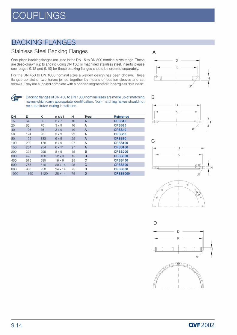
9.14
COUPLINGS
BACKING FLANGES
One-piece backing flanges are used in the DN 15 to DN 300 nominal sizes range. Theseare deep-drawn (up to and including DN 150) or machined stainless steel. Inserts (pleasesee pages 9.18 and 9.19) for these backing flanges should be ordered separately.
For the DN 450 to DN 1000 nominal sizes a welded design has been chosen. Theseflanges consist of two halves joined together by means of location sleeves and setscrews. They are supplied complete with a bonded segmented rubber/glass fibre insert.
Stainless Steel Backing Flanges
DN15254050801001502003004506008001000
ReferenceCRSS15CRSS25CRSS40CRSS50CRSS80CRSS100CRSS150CRSS200CRSS300CRSS450CRSS600CRSS800CRSS1000
D64851061241552002843254286157559861160
K507086981331782542954005857109501120
n x d13 x 73 x 93 x 93 x 96 x 96 x 96 x 118 x 912 x 916 x 920 x 1424 x 1428 x 14
H10161922252727151525257575
TypeAAAAAAABBCCDD
Backing flanges of DN 450 to DN 1000 nominal sizes are made up of matchinghalves which carry appropriate identification. Non-matching halves should notbe substituted during installation.

9.15
COUPLINGS
FIXED POINT FLANGES
In the DN 15 to DN 600 nominal size range, fixed points are created by using acombination of standard couplings with support flanges and vessel holders and supportrings with tubular support frames in the structure (please see section 10 »Structures &Supports«). In the DN 800 and DN 1000 nominal sizes, special couplings are used tomount fixed points directly onto a profile steel support frame. For this purpose a specialfixed point flange should be used as the lower flange. This is fixed directly to the U-profileframe by means of four support lugs set at 90°.
All fixed point flanges are supplied in epoxy resin painted steel or stainless steel. Theyconsist of two halves joined together by means of location sleeves and set screws.
ReferenceStainless steel
CRSSF800CRSSF1000
ReferenceSteel
CRCSF800CRCSF1000
n x d1
24 x 1428 x 14
DN
8001000
D
9961170
K
9501120
K1
10501220
n x d2
4 x 184 x 18
H
120120
H1
135135
Steel and Stainless Steel Fixed Point Flanges
These backing flanges are made up of matching halves which carryappropriate identification. Non-matching halves should not be substitutedduring installation.

9.16
COUPLINGS
ADAPTOR FLANGES
ADAPTOR FLANGES
Where borosilicate glass 3.3 components have to be connected to flanges onequipment in other materials of construction, different PCDs, bolt hole diameters andbolt configurations are generally involved. These adaptor flanges provide a solution tosuch problems. They have a larger than normal outside diameter and can be suppliedeither undrilled or drilled to a particular specification.
As the bolting force applicable to couplings for glass components is lower than for metalequipment, we supply adaptor flanges predrilled to your specifications but with bolt holediameters identical to those in our standard backing flanges. Where the mating flangeis drilled to take larger bolts, reducing washers (please see page 9.21) should be used.
Adaptor flanges can be supplied in cast iron (in the DN15 to DN150 nominal sizes) ormachined steel (in the DN200 and DN 300 nominal sizes) with an epoxy resin paintingor alternatively stainless steel.
If the flanges are required with a hole configuration differing from thoseindicated below, please provide details when ordering.
Undrilled Adaptor FlangesReferenceStainless steel
CRSSU15CRSSU25CRSSU40CRSSU50CRSSU80CRSSU100CRSSU150CRSSU200CRSSU300
ReferenceCast iron/Steel
CRCSU15CRCSU25CRCSU40CRCSU50CRCSU80CRCSU100CRCSU150CRCSU200CRCSU300
DN
1525405080100150200300
D
95115150165200220285325460
H
101619222527271515
Type
AAAAAAABB

9.17
COUPLINGS
ADAPTOR FLANGES
ADAPTOR FLANGES
Adaptor Flanges drilled to ANSI, Class 150
Adaptor Flanges drilled to EN 1092, PN 10
ReferenceStainless steel
CRSSE15CRSSE25CRSSE40CRSSE50CRSSE80CRSSE100CRSSE150
ReferenceCast iron
CRCSE15CRCSE25CRCSE40CRCSE50CRCSE80CRCSE100CRCSE150
DN
1525405080100150
D
95115150165200220285
H
10161922252727
ReferenceStainless steel
CRSSA15CRSSA25CRSSA40CRSSA50CRSSA80CRSSA100CRSSA150CRSSA200CRSSA300
ReferenceCast iron/Steel
CRCSA15CRCSA25CRCSA40CRCSA50CRCSA80CRCSA100CRCSA150CRCSA200CRCSA300
DN
1525405080100150200300
D
95115150165200220285325460
H
101619222527271515
Type
AAAAAAABB
K
6585110125160180240
n x d1
4 x 74 x 94 x 94 x 98 x 98 x 98 x 11
K
607998121152190241298432
n x d1
4 x 74 x 94 x 94 x 94 x 98 x 98 x 118 x 912 x 9
In nominal sizes DN 200 and DN 300 plastic flanges (type »CRP..«) and stainlesssteel flanges (type »CRSS..«) are drilled to EN 1092, PN 10 (PCD only) and canalso be used as adaptor flanges.

9.18
COUPLINGS
Inserts are fitted to avoid direct contact between the flange and glass buttress end andto compensate for any unevenness resulting from manufacturing tolerances. Theyshould always be renewed if a joint is dismantled.
The »DN« figure in the table below refers to the nominal size of the coupling.
INSERTS
INSERTSPlastic InsertsWhere small nominal sizes are involved, for example in interconnecting pipework in andbetween units, the number of joints that has to be made is relatively large and insertsthat are especially easy to install can reduce the time and effort involved quiteconsiderably. This requirement can be best catered for by using these one-piece insertsmade of specific polyamide in the DN 15 to DN 150 nominal size range and the hingedDuroplast with rubber/glass fibre layer version in the DN 200 and DN 300 nominal sizes.
ReferenceCIP15CIP25CIP40CIP50CIP80CIP100CIP150CIP200ACIP300A
DN1525405080100150200300
D37526882113150202254359
H121922252933331818
TypeAAAAAAABB

9.19
COUPLINGS
Rubber/Glass Fibre Inserts
This segmented version is for the DN 450 to DN 1000 nominal size range. The insertsare bonded to the flange, i.e. they are included in the supply. They only need to beordered separately when required as spares.
The black side of the insert should be bonded to the flange.
INSERTS
INSERTSRubber/Aramide Fibre InsertsIn applications involving glass fibre reinforced polyester coated borosilicate glass 3.3components, identified by the suffix »C« (please see section 1 »Technical Information«),these thinner rubber/aramide fibre inserts should be used in the DN 15 to DN 150nominal size range. All the other coupling components are the same as the standardversion.
ReferenceCIC15CIC25CIC40CIC50CIC80CIC100CIC150
DN1525405080100150
L89133180220308411570
H10161922252727
H12,53,5455,566,5
DN4506008001000
ReferenceCIR450CIR600CIR800CIR1000
H16666
n x L2 x 7952 x 10474 x 7004 x 837
H13131313
These inserts should never be used with uncoated or Sectrans coated glasscomponents.
The side of the insert which is marked in blue should be fitted towards the glassflange.

9.20
COUPLINGS
COMPRESSION SPRINGSCompression springs are used to set the correct bolt load and to maintain it after thegasket has settled, thus ensuring that the coupling remains leak-free. These springs aresupplied exclusively in stainless steel.
To achieve the required sealing load and to ensure that the coupling bolts aretightened evenly, first make the nuts finger-tight and then finish off with aspanner (from DN 80 upwards alternating between bolts on opposite sides ofthe coupling). The free length L0 and compressed length L1 are shown in thetable below.
In addition, with couplings in the DN 450 to DN 1000 range the compressedlength L1 should be checked after the plant is heated for the first time and ifnecessary the set screws retightened.
In the table below »DN« refers to the nominal size of the coupling.
Suitablefor coupling DN
15254050801001502003004506008001000
Reference
DFSS6.5DFSS8.5DFSS8.5DFSS8.5DFSS8.5DFSS8.5DFSS10.5DFSS10.5DFSS10.5DFSS10.5DFSS13DFSS13DFSS13
d
6,58,58,58,58,58,510,510,510,510,5131313
L0
13,5202020202030303030393939
L1
1114,514,514,514,514,524,524,524,524,5313131

9.21
COUPLINGS
REDUCING WASHERS
Reducing Washers for Flanges to ANSI, Class 150
Reducing Washers for Flanges to EN 1092, PN 10
Whenever borosilicate glass 3.3 components have to be connected to those of othermaterials of construction, we recommend the use of predrilled adaptor flanges (pleasesee page 9.17). The diameter of the bolt holes in these flanges is identical to theequivalent type of standard flange described on pages 9.12 and 9.14 in order to limitthe bolting force to the figure applicable to glass components.
As the mating flange is usually drilled to take larger bolts, reducing washers should beused to locate the smaller bolts centrally in the mating flange hole. These are suppliedin stainless steel as standard.
The »DN« figure in the table below refers to the nominal size of the coupling.
Reducing washers can be supplied in other sizes on request.
Suitablefor coupling DN
152540-100150200-300
Reference
RWSS13/7RWSS13/9RWSS17/9RWSS21/11RWSS21/9
d1
799119
D
1313172121
H
33333
Suitablefor coupling DN
1525-4050-100150200300
Reference
RWSS15/7RWSS15/9RWSS18/9RWSS21/11RWSS21/9RWSS24/9
d1
7991199
D
151518212124
H
333333

9.22
COUPLINGS
GASKETSPTFE ‘O’ Ring GasketsThis simple type is the most widely used gasket. It is self-centring on the periphery ofthe pipe end and up to and including DN 300 the sealing ‘O’ ring sits in a groove on thebuttress end face.
‘O’ ring gaskets are made to the highest standards from pure, high quality PTFE.
‘O’ ring gaskets are also suitable in many cases for connections tocomponents in other materials of construction provided the surface does notexhibit any great unevenness. We would be happy to advise you in cases ofdoubt.
ReferenceTR15TR25TR40TR50TR80TR100TR150TR200TR300TRN450TRN600TR800TR1000
DN15254050801001502003004506008001000
d323344861881211722203214926468711050
GASKETSThe choice of the correct gasket is of crucial importance for the proper functioning ofborosilicate glass 3.3 plant and pipeline as well as for connections to components inother materials of construction. Depending on the particular application, a suitablegasket can be selected from the four basic versions described below.
Special gaskets and gaskets in other materials can also be supplied to special order.

9.23
COUPLINGS
GASKETS
GASKETSFlat Gaskets
GMP-Compliant Gaskets
If borosilicate glass 3.3 components have to be connected to PTFE-lined components,we recommend the use of a flat gasket in addition to the ‘O’ ring gasket. The standardbolting forces applicable to the connection of glass components are then adequate forthese applications and the ‘O’ ring cannot press into the PTFE sealing surface. Theseflat gaskets are also made from a PTFE material of selected quality.
The essential difference between this special type and the version described on page9.22 is that the seal between the glass components is made on the internal bore. To dothis it was necessary to replace the ‘O’ ring with a flat, slender sealing bead. The samequality material is used as for the »TR..« type.
In addition, these gaskets have a double collar that prevents the product escapingradially in the event of leakage.
ReferenceTRGMP15TRGMP25TRGMP40TRGMP50TRGMP80TRGMP100TRGMP150TRGMP200TRGMP300TRNGMP450TRNGMP600
DN1525405080100150200300450600
d32334486188121172220321509662
ReferenceTP15TP25TP40TP50TP80TP100TP150TP200TP300
DN1525405080100150200300
D2942577099133185233338
d11727405177106156205302

9.24
COUPLINGS
GASKETSFlexible Gaskets
These flexible gaskets are ideal for applications in which angular deviations resulting frommanufacturing tolerances have to be corrected or where a ‘fall’ has to be createddeliberately. The outside of the gasket is made from pure PTFE of selected quality andthe ring and washers from stainless steel.
Deflections of up to 3° (equivalent to 52mm/m) are possible. Up to a temperature of 180ºC, the permissible operating pressure is the same as for glass components of the samenominal size.
If earthing straps are required for flexible gaskets to discharge electrostatic charges, theyshould be ordered separately. They are also suitable for retrofitting.
ReferenceKSG15KSG25KSG40KSG50KSG80KSG100KSG150
DN1525405080100150
d32334486188121172
L11121416202228

9.25
COUPLINGS
BELLOWS
Permissible operating conditions for »FB..« bellows
Permissible operating conditions for »VB..«, bellows
Bellows are important elements in the construction of borosilicate glass 3.3 plant andpipeline. They can be used not only to compensate for expansion and contraction dueto changes in temperature but also to avoid stress within plant or to ensure stress-freeconnection to other components, usually in other materials, which could induce vibration(e.g. service lines, pumps, stirred vessels, etc.). The versions described below take intoaccount these various applications.
Bellow flanges are supplied in either epoxy resin coated, spheroidal graphite, cast ironor stainless steel. Screws, nuts and compression springs are stainless steel in bothversions.
The relationship between permissible operating pressure and temperature forthe various types of bellows is indicated in the tables below. If used at themaximum permissible operating temperature of 200 ºC, they are only suitablefor use without any internal pressure. Intermediate figures can be interpolated.
As this table indicates, »FB..« type bellows of DN 80 and above cannot beused under vacuum at temperatures in excess of 100 ºC. In such cases type»VB..« vacuum bellows, which have an internal stiffening tube, should be used.
The bellows are set to the correct length with the permitted amount ofmovement ±DL (please see table) using locknuts before leaving the factory.The adjustment of the locknuts at the time of installation and the support andrestraint of equipment should be such that the forces resulting from pressureor vacuum in bellows does not result in undue stresses in the pipework. Forfurther information please consult our sales engineers.
We can also supply bellows for higher operating pressures as well asdissipative PTFE bellows.
DN1525405080100150200300
20 °C-1 / +4-1 / +4-1 / +4-1 / +4-1 / +3-1 / +2-1 / +2-1 / +1-1 / +1
100 °C-1 / +3-1 / +3-1 / +3-1 / +2-1 / +2-1 / +2-1 / +1,5-1 / +1-1 / +0,7
160 °C-1 / +1,5-1 / +1,5-1 / +1,5-1 / +10 / +10 / +10 / +0,70 / +0,50 / +0,3
200 °CPermissible operating pressures (bar g)
unpr
essu
rised
DN80100150200300
20 °C-1 / +3-1 / +2-1 / +2-1 / +1-1 / +1
100 °C-1 / +2-1 / +2-1 / +1,5-1 / +1-1 / +0,7
160 °C-1 / +1-1 / +1-1 / +0,7-1 / +0,5-1 / +0,3
200 °CPermissible operating pressures (bar g)
unpr
essu
rised

9.26
COUPLINGS
BELLOWSVacuum Bellows for Connecting Glass to GlassThe complete assembly includes the high grade PTFE bellows (including stiffening tube)which is in contact with the product together with two flanges, limiting screws, whichensure that the maximum permissible movement is not exceeded, and the ancillaryitems such as studs etc. for the couplings.
ReferenceStainless steel
VBSS80VBSS100VBSS150VBSS200VBSS300
ReferenceCast iron
VBCS80VBCS100VBCS150VBCS200VBCS300
DN
80100150200300
L±³L7376797979
± 6± 6± 6± 6± 6
D
190200280345460
d3
88121172220321
K
133178254295400
n x d1
6 x M86 x M86 x M108 x M812 x M8
BELLOWSBellows for Connecting Glass to GlassThe complete assembly includes the high grade PTFE bellows which is in contact withthe product together with two flanges, limiting screws which ensure that the maximumpermissible movement is not exceeded and the ancillary items such as studs etc. forthe couplings.
ReferenceStainless steel
FBSS15FBSS25FBSS40FBSS50FBSS80FBSS100FBSS150FBSS200FBSS300
ReferenceCast iron
FBCS15FBCS25FBCS40FBCS50FBCS80FBCS100FBCS150FBCS200FBCS300
DN
1525405080100150200300
L±³L354352506870737373
± 5± 5± 5± 6± 6± 6± 6± 6± 6
D
80105125140190200280345460
d3
2334486188121172220321
K
50708698133178254295400
n x d1
3 x M63 x M83 x M83 x M86 x M86 x M86 x M108 x M812 x M8

9.27
COUPLINGS
BELLOWS
ANSI, Class 150
EN 1092, PN 10
ReferenceStainless steel
FBSSA15FBSSA25FBSSA40FBSSA50FBSSA80FBSSA100FBSSA150FBSSA200FBSSA300
ReferenceCast iron
FBCSA15FBCSA25FBCSA40FBCSA50FBCSA80FBCSA100FBCSA150FBCSA200FBCSA300
DN
1525405080100150200300
L±³L
354352506870737373
± 5± 5± 5± 6± 6± 6± 6± 6± 6
D
95115150165200220285345460
d3
2334486188121172220321
d4
28445871100128178231335
K
50708698133178254295400
K1
607998121152190241298432
E
81213141717191919
n x d1
3 x M63 x M83 x M83 x M86 x M86 x M86 x M108 x M812 x M8
n x d2
4 x 74 x 94 x 94 x 94 x 98 x 98 x 118 x 912 x 9
Bellows for Connecting Glass to other materialsThis version comprises the high grade PTFE bellows which is in contact with the producttogether with two different types of flange, limiting screws, which ensure that themaximum permissible movement is not exceeded, and the ancillary items such as studsetc. for the coupling on the glass side and reducing washers for the other side.
Both flanges supplied with these bellows are sized for the bolting forces and bolt sizes(for hole diameter please see page 9.12) appropriate to glass plant. When connectingto flanges in other materials that usually have larger holes, the reducing washers referredto above (please see also page 9.21) should be used.
We can also supply bellows for coupling to flanges with different hole configurations andsealing faces.
ReferenceStainless steel
FBSSE15FBSSE25FBSSE40FBSSE50FBSSE80FBSSE100FBSSE150FBSSE200FBSSE300
ReferenceCast iron
FBCSE15FBCSE25FBCSE40FBCSE50FBCSE80FBCSE100FBCSE150FBCSE200FBCSE300
DN
1525405080100150200300
L±³L
354352506870737373
± 5± 5± 5± 6± 6± 6± 6± 6± 6
D
95115150165200220285345460
d3
2334486188121172220321
d4
28445871100128178231335
K
50708698133178254295400
K1
6585110125160180240295400
E
81213141717191919
n x d1
3 x M63 x M83 x M83 x M86 x M86 x M86 x M108 x M812 x M8
n x d2
4 x 74 x 94 x 94 x 98 x 98 x 98 x 118 x M812 x M8

9.28
COUPLINGS
BELLOWSVacuum Bellows for Connecting Glass to other materials
ANSI, Class 150
EN 1092, PN 10
This version comprises the high grade PTFE bellows (including stiffening tube) which isin contact with the product together with two different types of flange, limiting screws,which ensure that the maximum permissible movement is not exceeded and the ancillaryitems such as studs etc. for the coupling on the glass side and reducing washers forthe other side.
Both flanges supplied with these bellows are sized for the bolting forces and bolt sizes(for hole diameter please see page 9.12) appropriate to glass plant. When connectingto flanges in other materials that usually have larger holes, the reducing washers referredto above (please see also page 9.21) should be used.
We can also supply bellows for coupling to flanges with different hole configurations andsealing faces.
ReferenceStainlesssteel
VBSSE80VBSSE100VBSSE150VBSSE200VBSSE300
ReferenceCast iron
VBCSE80VBCSE100VBCSE150VBCSE200VBCSE300
DN
80100150200300
L±³L
7376797979
± 6± 6± 6± 6± 6
D
200220285345460
d3
88121172220321
d4
100128178231335
K
133178254295400
K1
160180240295400
E
1717191919
n x d1
6 x M86 x M86 x M108 x M812 x M8
n x d2
8 x 98 x 9 8 x 118 x M812 x M8
L±³L
7376797979
± 6± 6± 6± 6± 6
D
200220285345460
d3
88121172220321
d4
100128178231335
K
133178254295400
K1
152190241298432
E
1717191919
n x d1
6 x M86 x M86 x M108 x M812 x M8
n x d2
4 x 98 x 9 8 x 118 x M812 x M8
ReferenceStainlesssteel
VBSSA80VBSSA100VBSSA150VBSSA200VBSSA300
ReferenceCast iron
VBCSA80VBCSA100VBCSA150VBCSA200VBCSA300
DN
80100150200300

9.29
COUPLINGS
METAL/PTFE SPACERSThese components must always be used as interface spacers when connectingborosilicate glass 3.3 to other materials where a direct connection is not possiblebecause either the inside diameters are different or the mating surface has a highlyradiused edge, e.g. on a glass lined branch.
The spacers are in the form of a stainless steel disk, with two soft insert rings and a "U”section high grade PTFE sheath.
ReferenceEMP25/25EMPA25/25EMP40/32EMP40/40EMP50/50EMP50/65EMP80/65EMP80/80EMP100/80EMP100/100EMP150/150EMP150/200EMP200/200EMP200/250EMP300/300EMP450/450EMP600/600EMP800/800EMP1000/1000
DN25254040505080801001001501502002003004506008001000
DN12525324050656580801001502002002503004506008001000
D6850788810212212213813815821226826832037054470010151230
d454406670821101101201201421942422422983445006408401050
d33434484860.560.58888120.5120.5172172220220321492646--
L9999111112121515151616161621224646
TypeAAAAAAAAAAAAAAAAABB
K-----------------9501120
K1-----------------9501160
d118183030424268681001001501502002003004506007791000
n x d2-----------------24 x M1228 x M12
In nominal sizes DN 40 to DN 1000 the metal/PTFE spacers are suitable foruse with flanges drilled to EN 1092, PN 10 and ANSI, Class 150. In nominalsize DN25 the "EMPA25/25" type has to be used with ANSI Class 150 flanges.
The spacers can be clamped in the coupling in the case of components up toand including DN 600.
In the larger nominal sizes (DN 800 and DN 1000), both components arebolted separately to the spacer, its stainless steel ring being drilled to theappropriate PCDs and hole sizes.The stainless steel coupling screws, nuts andcompression springs are included in the supply.

9.30
COUPLINGS
PRODUCT HOSES
HOSES FOR SERVICE CONNECTIONS
These flexible hoses are ideal as product lines in applications calling for frequentmodifications, e.g. in pilot plant. They have also proven ideal for complicated pipingarrangements where space is limited. Another application for which they provide an idealsolution is to provide a variable height overflow.
The hoses are made of high grade PTFE shrunk onto a borosilicate glass 3.3 hoseconnector at each end and fixed with a special stainless steel clamp. Longer hoses upto a maximum length of 10 metres can be supplied on request.
Reference
SP15/500SP15/1000SP15/2000
SP25/500SP25/1000SP25/2000
SP40/500SP40/1000SP40/2000
DN
151515
252525
404040
d
101010
202020
363636
Minimumbend radius
505050
858585
120120120
L
50010002000
50010002000
50010002000
20 °C444
444
2,52,52,5
100 °C0,50,50,5
0,50,50,5
0,50,50,5
120 °C
All spiral hoses can be used under vacuum to an absolute pressure of 1 mbarat a temperature of 180º C. The permissible operating pressure as a functionof temperature is indicated in the table below.
Permissible operating pressures (bar g)
unpr
essu
rised
These hoses provide a flexible connection for service lines (steam, condensate, heatingfluids and coolants) to heat exchangers, boilers and borosilicate glass 3.3 jacketedcomponents or jacketed metal reaction vessels. The corrugated hose, woven sleeve andcoupling flange are stainless steel.
Hoses are also available in other lengths on request.
The permissible maximum operating pressure for these hoses is 16 bar g andthe permissible operating temperature is -30/+300 ºC.
The permissible operating conditions for the components to which they areconnected should also be taken into account.
All hoses can also be supplied with woven glass fibre fabric insulation. In suchcases the suffix »IN« should be added to the catalogue reference, e.g.»MSCIN25«.

9.31
COUPLINGS
HOSES FOR SERVICE CONNECTIONS
HOSES FOR SERVICE CONNECTIONSwith connections to EN 1092, PN 16
with QVF/EN 1092, PN 16 connectionsThese are used with heat exchangers and jacketed components with borosilicate glass3.3 jacket. A complete stainless steel coupling including gasket for connection to theglass side branch is included in the supply.
These hoses are used with metal immersion heat exchangers, heating baths and shelland tube heat exchangers with metal headers. One end is fitted with a loose flange forease of assembly.
ReferenceMSC15MSC25MSC50
DN152550
DN1152550
L100010001000
K6585125
n x d4 x 144 x 144 x 18
E141618
ReferenceMSCE15MSCE25MSCE50
DN152550
L100010001000
K6585125
n x d4 x 144 x 144 x 18
E141618
E1283236

9.32
COUPLINGS
COMPLETE COUPLINGS FOR BUTTERFLY VALVES
COMPLETE COUPLINGS FOR BUTTERFLY VALVESfor fitting between glass buttress ends
These complete couplings are designed for the installation of butterfly valves (please seesection 3 »Valves & Filters«) between borosilicate glass 3.3 buttress ends or betweenglass and metal flanges.
In this case, the couplings comprise two stainless steel rings with a "U” section highgrade PTFE sheath, two spheroidal graphite cast iron flanges (up to DN 150 nominalsize) or plastic flanges (DN 200 and 300 nominal size) with inserts and the appropriatequantity of stainless steel reducing washers, set screws, compression springs and nuts.
Stainless steel flanges can also be supplied on request.
If the valves are installed between glass fibre reinforced polyester coatedglass components (with the suffix »C”« in the catalogue reference), thinnerinserts are required for nominal sizes DN 50 to DN 150. In such cases thesuffix »C« should also be added to the catalogue reference for the couplinge.g. »FVT../1C«.
ReferenceFVT50/1FVT80/1FVT100/1FVT150/1FVT200/1
DN5080100150200
L7074808896
D165200220285340
K125160180240295
n x d14 x M88 x M88 x M88 x M108 x M8
TypeAAAAB
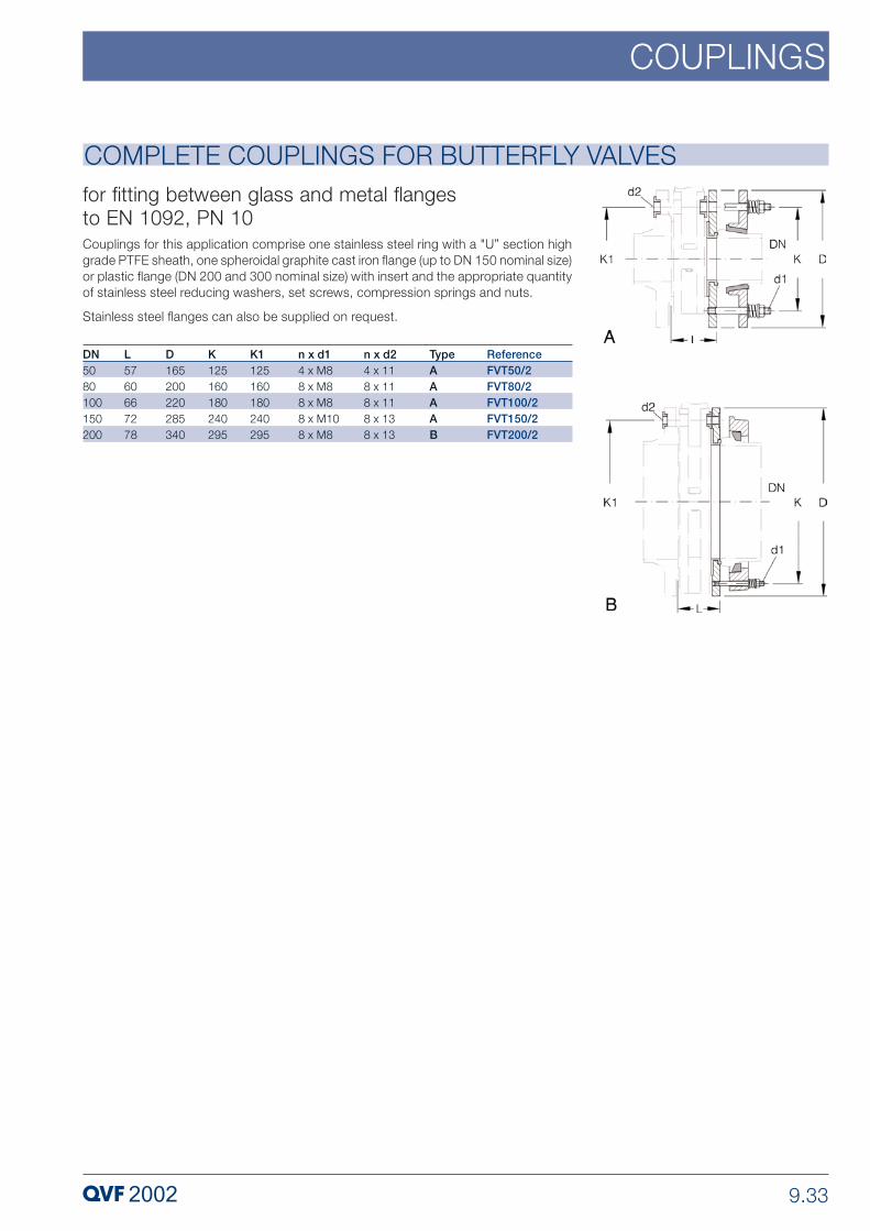
9.33
COUPLINGS
COMPLETE COUPLINGS FOR BUTTERFLY VALVESfor fitting between glass and metal flanges to EN 1092, PN 10Couplings for this application comprise one stainless steel ring with a "U” section highgrade PTFE sheath, one spheroidal graphite cast iron flange (up to DN 150 nominal size)or plastic flange (DN 200 and 300 nominal size) with insert and the appropriate quantityof stainless steel reducing washers, set screws, compression springs and nuts.
Stainless steel flanges can also be supplied on request.
ReferenceFVT50/2FVT80/2FVT100/2FVT150/2FVT200/2
DN5080100150200
L5760667278
D165200220285340
K125160180240295
K1125160180240295
n x d14 x M88 x M88 x M88 x M108 x M8
n x d24 x 118 x 118 x 118 x 138 x 13
TypeAAAAB

9.34
COUPLINGS
To connect to safety flat buttress ends a special coupling was developed, with thereference no. CPKFA.... and can be used for ball and socket glass-ends. Following partsare in the scope of supply:
2 x SCHD.../K (KF-backing flanges)1 x BEIL.../K (KF-insert)1 x KFA...(adaptor)1 x KRT..., or KRTN... (adaptor PTFE/gasket, Tmax = 130°C)
screws and springs
For the assembling of DN 80 take care the adaptor gasket KRT is exactly positioned.
ADAPTORS KF TO WPR
ReferenceCPKFA15CPKFA25
CPKFA40
CPKFA50
CPKFA80
CPKFA100
CPKFA150
DN1525405080100150

10 STRUCTURES & SUPPORTS
PROCESS PLANT COMPONENTS
P 310 e.3 Copyright © 2007, QVF Engineering GmbH. All rights reserved.

10.2
STRUCTURES & SUPPORTS
GeneralQVF structures are designed to support plant and other equipment comprisingcomponents exclusively or principally in borosilicate glass 3.3. Because of the specialrequirements resulting from the use of this material, structures are now available in theform of a proven modular system that not only meets standard requirements but alsoprovides or facilitates solutions for problems of a very special nature.
Basically these structures consist of steel tubing in three different diameters which isconnected using the appropriate fittings. As a result, the structures can not only bedismantled and reassembled whenever required but they can also be modified andadded to quite easily. The modular system also includes components for establishingfixed points, supporting spherical and cylindrical vessels and horizontal cylindricalcomponents plus a wide range of supports, to mention just the most important items.The result is an extremely flexible system.
The full range of components, which are available as standard in galvanised mild steeland to some extent in stainless steel, is described in this section. Special versions, whichare available on request, are referred to under the respective product descriptions.
A detailed listing of all structure components by »Description« and »CatalogueReference« can be found in the »Index«.
If any supports are required which you cannot find in this section, please contact us.Space does not permit the inclusion of every possible version in this catalogue.
Design of tubular structuresThe diameter of structure tubing to be used plus minimum dimensions, i.e. width anddepth of tubular structures are determined by the nominal size (cylindrical glasscomponents) or diameter (spherical vessels) and the weight of the components they aredesigned to support. Details can be found in the table below and the related illustration.If additional equipment or complicated pipework needs to be accommodated in astructure, appropriately larger sizes should be used.
The sizes of structure tubing and other fittings indicated for the various nominalsizes, shapes and configurations of glass components should be adhered to.If this is not possible due to special circumstances, please seek our advice onthis and any other problems relating to structures.
The figures for DN 800 and DN 1000 cylindrical components and 500 litrenominal capacity spherical vessels only apply to installations with a low totalweight. In all other cases, we recommend the use of a heavy duty fabricatedbase structure.
Columns
DN801001502003004504506006008001000
Cylindrical vessels
DN----450600600--800-
Spherical vesselsContents
l--5, 102050100, 200100, 200----
Structure tubediameter
mm2727424242426042606060
Structure dimension
L40050060070080010001100110014001600/15101930/1680
Structure dimensions for

10.3
STRUCTURES & SUPPORTS
The establishment of fixed points is of particular importance. They are formed bycombining a light duty support frame or heavy duty support frame with a coupling, asupport plate or a support element (vessel holder, angle bracket, etc.). Fixed points haveto carry the entire weight of a unit or column and should therefore, be located at thelowest point (in the case of a vessel holder) or lowest possible point (in the case of asupport plate) in the installation.
If there is the risk of vibration generated in the vicinity of glass units being transferred tothe tubular structure, appropriate preventive measures should be taken.
The structure components described on pages 10.5 to 10.8 can also be used tosupport platforms and walkways for the use of plant operators and maintenance staff.They are connected directly to the plant support structure which results in a particularlycompact design. The decking of these platforms and walkways is in the form of gridsor embossed metal sheets.
Where supports are used in a structure for individual components or assemblies, theseshould be installed in such a way that the glass components are subject in the main tocompressive forces. It has to be taken into consideration, that normally an additionalfixed point is created at such points.
Support structures must be sufficiently rigid to prevent any bending of the individualtubes in excess of the permissible amount and the subsequent transfer of external stressto the glass components. This is achieved by incorporating additional bracing
Glass components must be able to expand freely from a fixed point, thereforea bellows is generally fitted between two fixed points.
For rigidity at least two adjacent sides of the structure should be provided withdiagonal bracing. In addition, tall structures (e.g. for columns) should bebraced back to existing structural steelwork or the walls of the building.
Assembly of the glass components must always be started from the fixedpoint.
Glass units and their structures expand at different rates as a result of changein temperature. The unit must, therefore, be able to expand above the fixedpoint without restraint.
Guides giving lateral support must always be provided for units and columns.
If the overall height of the unit or column is fairly low this can be achieved byusing two »KK50-5« or »KK50-7« structure fittings each with one of the setscrews of a horizontally positioned coupling passing through them.
Above a certain height this is achieved with a light duty support frame whichcan also be used to support the weight of glass components during installationand maintenance work.
Guide elements should not be bolted rigidly to the unit or plant duringoperation.

10.4
STRUCTURES & SUPPORTS
Supporting Horizontal PipelineBoth horizontal and vertical pipelines must be supported at certain intervals to avoidsubjecting them to additional stress due to bending or lateral movement (e.g. on eitherside of bellows). The recommended spacing of horizontal pipeline supports as afunction of nominal size is indicated in the table below.
Clean Room DesignStainless steel structure, support and coupling components can be supplied for usein applications where clean room conditions apply (see also Section 9 »Couplings«).
We would be happy to advise you on the requirements applicable in each particularcase using the guidelines we have drawn up for the design of complete tubularstructures for use under clean room conditions.
PipelineDN1525405080100150200300
Gas
150020002500250030003000300030003000
Liquidρ = 1150020002000200020002500200020002000
Liquid ρ = 1,8100015001500150015002000200015001500
Maximum spacing of supports
L in mm for

10.5
STRUCTURES & SUPPORTS
STRUCTURE TUBINGThis tubing is used in conjunction with the structure fittings described on pages 10.6 to10.8 to form the basis of structures to support borosilicate glass 3.3. plant. Structuretubing is available in three sizes and can be supplied in galvanised mild steel or stainlesssteel. This is to take into account the fact that glass is used in areas where variousdegrees of corrosive atmosphere are encountered.
As it is important that the structure tubing should not bow by more than 2 mm, themaximum permissible free length of the tubing is dependent on the load it is carrying.This can be calculated, at a fixed point for example, as the sum of the weights of supportframes, glass components including couplings and liquid content. The number ofsupport points should also be taken into account. Further information can be found inthe illustration alongside and the diagram below.
The structure components described below and on pages 10.6 to 10.8 can also be usedto support platforms for the use of plant operators and maintenance staff. They areconnected direct to the plant support structure which results in a particularly compactdesign. The decking of these platforms is in the form of grids or embossed metal sheets.
Permissible structure tubing load as a function of unsupported length
If individual lengths of tubing are required cut to a specific length, please addthe length (in mm) to the catalogue reference.
For tubular structures that are to be installed in clean rooms, we can alsosupply stainless steel tubes with a ground finish on request. The cataloguereference is then for example: »M-RO7E/..«.
D
27426075
Fitting size
57910
L ReferenceGalvanised
RO5/....RO7/....RO9/....RO10/....
ReferenceStainless steel
--RO9E/....-
ReferenceGround
M-RO5E/....M-RO7E/....--va
riabl
e

10.6
STRUCTURES & SUPPORTS
STRUCTURE FITTINGSClosed sided fittings are used principally in conjunction with structure tubing to buildcomplete structures where the design has been fixed prior to installation together withthe necessary support frames, brackets, diagonal bracing and supports. In such casessubsequent modifications can only be carried out on a restricted basis.
If it is expected at the time of the original installation that extensive modification may berequired or will have to be carried out subsequently, we recommend that the use of opensided structure fittings be considered. They are also ideal for items added to thestructure at a later stage ( e.g. support frames) or extra fittings (e.g. brackets).
We can supply a comprehensive range of closed and open sided structure fittings tocater for the various applications and the many different requirements encountered inpractice. The finishes available are galvanised (catalogue reference »KK..« and »KKO..«),coated blue (catalogue reference »M-KK..« and »M-KKO..«) and to some extent stainlesssteel (catalogue reference »KK.. E« and »KKO..E«). Further details, including details ofthe various possible uses of the individual fittings and the necessary accessories, canbe found in the tables on pages 10.7 and 10.8.
The structure components described on pages 10.5 to 10.8 can also be used tosupport platforms for the use of plant operators and maintenance staff. They areconnected directly to the plant support structure which results in a particularly compactdesign. The decking of these platforms is in the form of grids or embossed metal sheets.
If type »KKO..« structure fittings are fixed to horizontal tubes, they shouldalways be located on top of the tube, so that a closed assembly is ensured.

10.7
STRUCTURES & SUPPORTS
STRUCTURE FITTINGSClosed Sided Fittings
For tubediam.
27 mm42 mm60 mm
27 mm42 mm60 mm
27 mm42 mm60 mm
27 mm42 mm60 mm
27 mm42 mm60 mm
27 mm42 mm60 mm
27 mm42 mm60 mm
27 mm42 mm60 mm
27 mm42 mm60 mm
27 mm42 mm60 mm
27 mm42 mm60 mm
27 mm42 mm60 mm
27 mm42 mm60 mm
27 mm42 mm60 mm75 mm
Reference
KK10-5KK10-7KK10-9
KK14-5KK14-7KK14-9
KK15-5 KK15-7KK15-9
KK21-5KK21-7KK21-9
KK26-5KK26-7KK26-9
KK35-5KK35-7KK35-9
KK40-5KK40-7KK40-9
KK45-5KK45-7KK45-9
KK49-5KK49-7-
KK50-5KK50-7-
KK62-5KK62-7KK62-9
KK97-5KK97-7KK97-7
KK99-5KK99-7KK99-7
RP-5RP-7RP-9RP-10
Referencecoated blue
M-KK10-5M-KK10-7M-KK10-9
M-KK14-5M-KK14-7M-KK14-9
M-KK15-5 M-KK15-7M-KK15-9
M-KK21-5M-KK21-7M-KK21-9
M-KK26-5M-KK26-7M-KK26-9
M-KK35-5M-KK35-7M-KK35-9
M-KK40-5M-KK40-7M-KK40-9
M-KK45-5M-KK45-7M-KK45-9
M-KK49-5M-KK49-7-
M-KK50-5M-KK50-7-
M-KK62-5M-KK62-7M-KK62-9
---
---
----
ReferenceStainless steel
-KK10-7E-
---
---
-KK21-7E-
-KK26-7E-
-KK35-7E-
-KK40-7E-
-KK45-7E-
KK49-5E--
---
-KK62-7E-
DI916-12x16-A2DI916-16x16-A2DI916-16x16-A2
6mm8mm8mm
----
Purpose
Single tube socket
Tube coupler (to lengthen tubes)
90° Elbow fitting
Corner fitting
Side fitting
For tee connections
For cross connections
For fitting removable tubes
For diagonals in conjunction withKKO50-7 and KKO50-9 respectively
For supporting flanges in conjunctionwith KKO45-75 and KKO45-95 respectively (see p. 10.8)
Structure foot
Replacement grub screw
Replacement Allen keySteel (inches)Stainless steel (metric)
Plug for tube ends

10.8
STRUCTURES & SUPPORTS
STRUCTURE FITTINGSOpen Sided Fittings
For tubediam.
27 mm42 mm60 mm
---
27 mm42 mm60 mm
27 mm42 mm60 mm
27 mm42 mm60 mm
27 mm42 mm60 mm
27 mm42 mm60 mm
27 mm42 mm60 mm
27 mm42 mm60 mm
27 mm42 mm60 mm
Reference
-KKO10-7-
KKO17-109
-KKO21-7-
-KKO26-7-
-KKO35-7-
-KKO45-75KKO45-95
KKO45-5KKO45-7KKO45-97
KKO50-5KKO50-7KKO50-9
DI916-12x16-STDI916-16x20-STDI916-16x20-ST
6mm8mm8mm
Referencecoated blue
-M-KKO10-7-
M-KKO17-109
-M-KKO21-7--
M-KKO26-7-
-M-KKO35-7-
-M-KKO45-75M-KKO45-95
M-KKO45-5M-KKO45-7M-KKO45-97
M-KKO50-5M-KKO50-7M-KKO50-9
---
---
ReferenceStainless steel
---
-
---
---
---
-KKO45-75E-
---
KKO50-5EKKO50-7E
DI916-12x16-A2DI916-16x20-A2DI916-16x20-A2
6mm8mm8mm
Purpose
For addition of single tubes
For fitting removable 75 mm diam.tubes with support framesRRDN600//2.5 75 mm diam. tube
Corner socket for addition of extratubes
Corner socket for addition of extratubes
Corner socket for addition of extratubes
For addition of removable 27 mmdiam. tubes, support framesand brackets
For support frames
For diagonals in conjunction with fittings KK49-7 and KK49-5
Replacement grub screw (metric)
Replacement Allen key

10.9
STRUCTURES & SUPPORTS
One of the best ways to fix supports in structures is to use screwed rod. This isconnected directly to the tubular structure using structure fittings or, where heavycomponents are involved, using structure bushes as well. In addition, structure bushesare also required to fix support brackets and support saddles (see pages 10.14 and10.15) in the structure.
In special cases, it is also possible to fix vessel holders and support rings (see pages10.13 and 10.14) and column support plates (see page 10.12) directly to the tubularstructure using structure bushes. There is then no need to use a support frame (seepage 10.11).
REDUCING FITTINGSIf it is necessary for design or technical reasons to reduce the diameter of the tubingused in a support structure, the reducing fittings listed below can be used. In principle,these should be handled in the same way as »KK14.. « sleeve couplings.
STRUCTURE BUSHES
ReferenceStainless steel
RC75ERC97E
ReferenceGalvanised
RC75RC97
D2
2742
D1
4260
D3
7090
L
100125
D4
4870
L1
5162
L2
3951
ReferenceStainless steel
RRM8-5RRM10-5RRM8-7RRM10-7RRM12-7RRM16-7RRM12-9RRM16-9
For tube
2727424242426060
L
5778577875957595
M
81081012161216
H
5052686971749598
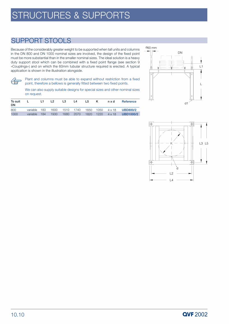
10.10
STRUCTURES & SUPPORTS
SUPPORT STOOLS
Because of the considerably greater weight to be supported when tall units and columnsin the DN 800 and DN 1000 nominal sizes are involved, the design of the fixed pointmust be more substantial than in the smaller nominal sizes. The ideal solution is a heavyduty support stool which can be combined with a fixed point flange (see section 9»Couplings«) and on which the 60mm tubular structure required is erected. A typicalapplication is shown in the illustration alongside.
Plant and columns must be able to expand without restriction from a fixedpoint, therefore a bellows is generally fitted between two fixed points.
We can also supply suitable designs for special sizes and other nominal sizeson request.
Reference
UBD800/2UBD1000/2
n x d
4 x 184 x 18
L
variablevariable
To suit DN
8001000
L1
183184
L3
15101680
L2
16001930
L4
17402070
L5
16501820
K
10501220

10.11
STRUCTURES & SUPPORTS
ColumnsDN Fig. A80100150150200300
--450450600600
Support ringsFig. C--VRSE5, VRSE10VRSE5, VRSE10VRSE20,-
--(CCS450RRD or----
Vessel supportsFig. C----VHZ300, VHZE300VHS50, VHSE50VHS100, VHSE100VHZ450, VHZE450--CSS450RRD)VHS200, VHSE200--
Support platesFig. B
CTF80CTF100CTF100CTF150CTF200
CTF300CTF300--CTFN450CTFN450
Reference
RRD80RRD100RRD150RRD150/1.25RRD200RRD300
RRDN400RRDN400/2RRDN450RRDN450/2RRDN600RRDN600/2.5
SUPPORT FRAMESThese frames are used in the DN80 to DN600 range of nominal sizes as a base elementfor a fixed point and are installed horizontally using tubes and fittings on a framework inthe structure. Cylindrical components are then fixed directly via a coupling (see pages9.4 to 9.10) or indirectly via support plates (see page 10.12). Spherical and cylindricalvessels are supported indirectly via vessel holders or support rings (see pages 10.13and 10.14 ). These elements are connected to the support frames using screwed rodwhich, for stability reasons, should be as short as possible. They are also used to alignthe couplings or structure elements supported on the support frames.
Support frames are supplied in galvanised finish or stainless steel and have a QVF PCD.The material required for fixing the support frames and the screwed rod required (seeabove) are included in the supply.
Information about using these support frames with couplings, vessel holders, etc. canbe found in the respective product description.
Plant and columns must be able to expand without restriction from a fixedpoint, therefore a bellows is generally fitted between two fixed points.
Plant and columns must always be provided with lateral support. Above acertain height, support frames should be used for this purpose.
Typical applications
ReferenceStainless steel
RRD80ERRD100ERRD150ERRD150/1.25ERRD200ERRD300ERRDN400ERRDN400/2E RRDN450ERRDN450/2ERRDN600ERRDN600/2.5E
ReferenceGalvanised
RRD80RRD100RRD150RRD150/1.25RRD200RRD300RRDN400RRDN400/2 RRDN450RRDN450/2RRDN600RRDN600/2.5
n x d
3 x M83 x M83 x M103 x M103 x M8/M103 x M8/M123 x M123 x M123 x M123 x M123 x M123 x M12
Tubediam
272727424242426042604275
L
92107145147168218273273313313379375
DN
80100150150200300400400450450600600
L1
51638388120119115115133133226230
L3
150200200200200210270340280340330410
L2
195235300300305436550575640660700755
K
133178254254280-295395-400495495585585710710
A
B
C

10.12
STRUCTURES & SUPPORTS
SUPPORT PLATESIndirectly installing cylindrical borosilicate glass 3.3 components on support framesusing support plates offers a significant benefit compared to the combination of acoupling and light duty support frame: the glass components above and below can beinstalled and dismantled independently from each other. As the PCD is different, thesupport flange remains firmly connected to the support frame or structure during suchwork.
Another benefit of the support plate is that the weight of the glass componentssupported on it only results in compressive stress therefore as a rule there is no needto compensate for this weight.
Support plates consist of a steel ring, which is primed and protected against corrosionby an epoxy resin paint, and a high grade PTFE sheath. The complete assembly alsoincludes the coupling components for the glass such as bolts, nuts, washers, andcompression springs but no flanges. As the support plate incorporates a sealing beadon both sides, no additional PTFE gaskets are required.
The support plate metal rings can also be supplied in stainless steel on request.
Reference
CTF80 CTF100
CTF150CTF200CTF300CTF300CTFN450
CTFN600
To suit support frame
RRD100RRD150RRD150/1.25RRD200RRD300RRDN400RRDN400/2RRDN600RRDN600/2.5U-section
n x d1
6 x M86 x M8
6 x M108 x M812 x M8
16 x M8
20 x M12
n x d2
3 x 93 x 11
3 x 113 x 143 x 14
3 x M12
3 x M16
Type
AA
AAA
B
B
D
205290
350430530
760
900
DN
80100
150200300
450
600
L
1818
202222
27
33
K1
178254
295400495
710
850
K
133178
254295400
585
710

10.13
STRUCTURES & SUPPORTS
These vessel holders are used to support borosilicate glass 3.3 spherical and cylindricalvessels with a nominal capacity of 50 litres and above. The lining of the holder is speciallyshaped to fit the outside of the particular vessel. The metal casing of the holder is castaluminium or steel (»VHS500« only) primed and epoxy resin painted to protect it againstcorrosion, or stainless steel respectively. All vessel holders have a QVF PCD.
VESSEL HOLDERS
Spherical Vessel Holders
Cylindrical Vessel Holders
Reference
VHS50VHS100VHS200VHS500
ReferenceStainless steel
VHSE50VHSE100VHSE200VHSE500
Type
BBBC
K
395400585800
d1
3 x M123 x M123 x M124 x 18
H
126122118267
D
440500620980
Spherical vesselCapacity (l)
50100200500
Support frame
RRD300RRD300RRDN450 u. 450/2-
L
270330360505
L3
99100112330
L1
15151512
L2
342346540566
To suit
ReferenceStainless steel
VRZE150VRZE200VHZE300VHZE450VHSE100VHZE800VHZE1000
Reference
--VHZ300VHZ450VHS100VHZ800VHZ1000
K
254254280395400710710
d1
3 x 113 x 113 x M103 x M123 x M123 x 143 x 14
(l)51020-50100-200300-400500750
H
--125125122162181
D
--320440500654736
Cylindrical vesselDN 1502003004506008001000
Support frame
RRD150 a. 150/1.25RRD150 a. 150/1.25RRD200RRD300RRD300RRDN600 a. 600/2.5RRDN600 a. 600/2.5
L
6888195240330455550
L3
64649999100209209
L1
10101515151010
L2
220220198342346574574
To suit: Type
AABBBDD

10.14
STRUCTURES & SUPPORTS
SPHERICAL VESSEL SUPPORT RINGS
ANGLED SUPPORT BRACKETS
This type of ring can be used to support borosilicate glass 3.3 spherical vessels up toa nominal capacity of 20 litres. They are stainless steel and are fitted with a close fittingsilicon rubber sleeve. All support rings are drilled to a QVF PCD.
An alternative method of supporting these small spherical vessels in a tubular structureis by means of support brackets (see page 10.15). These are connected to the couplingon the top neck and this then forms the fixed point.
These brackets are used to support horizontal assemblies in the DN150 to DN300nominal size range such as horizontal separators (see section 4 »Vessels & Stirrers«) orshell and tube heat exchangers (see section 5 »Heat Exchangers«). They are fitted to acoupling using longer set screws or fixed by means of »RRM..« structure bushes andclosed or open structure fittings (see pages 10.6 to 10.9) to cross members.
Angled support brackets are supplied with either a galvanised finish or stainless steelas standard. The material required for connection to the tubular structure (see above)should be ordered separately.
Reference
VRSE5VRSE10VRSE20
K
254254295
n x d
3 x 113 x 113 x 9
Spherical vesselCapacity (l)
51020
Support frame
RRD150 or 150/1.25RRD150 or 150/1.25RRD200
L
78106138
L3
6464104
L1
101010
L2
220220209
To suit
ReferenceStainless steel
SUA100ESUA150ESUA150ESUA150ESUA150ESUA150ESUA150ESUA150E
ReferenceGalvanised
SUA100SUA150SUA150SUA150SUA150SUA150SUA150SUA150
d
1314141414141414
DN100150150150200200300300
L
165208215208235243293295
H
89999999
K
178225240254280295395400
L1
110200200200200200200200
L2
3040404040404040
To suit

10.15
STRUCTURES & SUPPORTS
PIPELINE SUPPORT BRACKETSThese brackets are used in tubular support structures in conjunction with open sidedstructure fittings (see page 10.8), which guarantee the flexibility required in installation,and short lengths of structure tubing to provide a versatile support for borosilicate glass3.3. components. They are supplied in a galvanised finish as standard.
As these brackets have the same PCD as the corresponding flange, they can beconnected directly to a coupling. However, the standard set screws should be replacedby longer set screws or screwed rod which is available in all the normal diameters. Bothshould be at least 50 mm longer than the standard set screws to ensure an adequatesetting range.
Fixing pipeline support brackets couplings nearly always creates a fixed point,from which glass components must be able to expand without restriction,therefore a bellows is generally fitted between two fixed points.
If long horizontal tubes are required to connect pipeline support brackets tothe structure, these must be braced diagonally.
SUPPORT SADDLESThese support saddles with bracing strap are designed to support DN450 and DN600assemblies such as horizontal separators (see Section 4 »Vessels & Stirrers«) in tubular structures. The lower part consists of a steel bar with segmented rubber liningand a profiled steel support frame. It is fixed by means of »RRM.« structure bushes andclosed or open structure fittings (see pages10.6 to 10.9) to horizontal structure tubes.The upper part is a rubber lined metal strap braced to the lower part by means of captivescrewed rods and nuts.
Support saddles are supplied with either a galvanised finish or stainless steel asstandard. The material required for connection to the tubular structure (see above)should be ordered separately.
ReferenceStainless steel
SUS450ESUS600ESUS800E
ReferenceGalvanised
SUS450SUS600SUS800
d
181818
DN450600800
L2
405050
L1
300400630
L
280362475
To suit
ReferenceStainless steel
HK25EHK40EHK50EHK80EHK80/1.25EHK100/1.25EHK150/1.25EHK200/1.25EHK300/1.25E
ReferenceGalvanised
HK25HK40HK50HK80HK80/1.25HK100/1.25HK150/1.25HK200/1.25HK300/1.25
Type
AAAABBBBB
DN2540508080100150200300
L2
7,07,07,0163030405050
K
708698133133178254295400
d1
272727274242424242
d2
999912,512,512,51111
D
87103115156160205281328440
L1
272727303131313131
L
65657010080103140164220
To suit

10.16
STRUCTURES & SUPPORTS
PIPELINE SUPPORTSThese supports are used in conjunction with open sided structure fittings (please seepage 10.8) which guarantee the flexibility required in installation, or structure feet andshort lengths of structure tubing to support borosilicate glass 3.3 pipeline componentsin tubular structures and from walls. They consist of a two-piece rubber collar whichgrips the glass pipe firmly and a ‘U’ bolt fixed to a backplate. The latter has a socket sothat it can be connected to the structure.
Pipeline supports are supplied with metal parts either in galvanised finish or stainlesssteel as standard. When correctly installed they do not constitute a fixed point, i.e. theweight of vertical pipelines should be taken up by other means, e.g. using pipelinesupport brackets.
When these supports are used for horizontal pipelines the recommended spacingindicated on page 10.4 must be adhered to. In the case of vertical pipeline, the distancebetween two supports should not exceed 5 meters.
ReferenceStainless steel
HR15EHR25EHR40EHR50EHR80EHR100EHR150EHR200EHR300E
ReferenceGalvanised
HR15HR25HR40HR50HR80HR100HR150HR200HR300
DN1525405080100150200300
H1
8585110110165165270310390
H2
202020202020404040
d
282828282828284444
H
7373103103155155255299374
L
383856568181127154189
To suit

10.17
STRUCTURES & SUPPORTS
PIPE HANGERSThese hangers can be used to fix borosilicate glass 3.3 pipeline in structures and towalls. They comprise two parts, one having a captive nut welded to it into which M10or M12 screwed rod can be screwed. A lock nut is also required. When used in tubularstructures, the screwed rod is fixed with two nuts in closed sided (»KK50-5« or »KK50-7«) or open sided (»KKO50-5« or »KKO50-7«) structure fittings which guarantee thenecessary flexibility in installation. A special type of support can be supplied for wallfixing.
Pipe hangers are supplied in either galvanised finish or stainless steel as standard withrubber to prevent direct contact with the glass components. When correctly installedthey do not constitute a fixed point, i.e. the weight of vertical pipelines should be takenup by other means, e.g. using pipeline support brackets.
When these supports are used for horizontal pipelines the recommended spacingindicated on page 10.4 must be adhered to. In the case of vertical pipeline, the distancebetween two supports should not exceed 5 meters.
Structure fittings type »KK50-5« and »KKO50-5« require drilling out from 11to13 mm diameter.
ReferenceStainless steel
HS15EHS25EHS40EHS50EHS80EHS100EHS150EHS200EHS300E
ReferenceGalvanised
HS15HS25HS40HS50HS80HS100HS150HS200HS300
DN1525405080100150200300
H1
232334343434464646
d
M10M10M12M12M12M12M12M12M12
H
364248546983110137183
To suit

10.18
STRUCTURES & SUPPORTS
SAFETY SCREENSFitting support structures with safety screens meets two safety requirements at the sametime: operating personnel are protected from any hazards that may arise from possiblebreakages and the units are protected against mechanical damage arising from externalsources.
Safety screens consist of sheets of medium flexibility transparent PVC with highresistance to abrasion. To ensure good lateral stability, they have galvanised metal stripsbolted on both sides at the top and bottom. Hooks are also fitted to the top edge toenable the safety screen to be suspended from the structure.
Safety screens are 5 mm thick. Up to a width of 1100 mm they are supplied in one pieceas standard. Larger screens are two-piece with an overlap. The maximum possiblelength is 6 metres.
Safety screens can also be supplied on request in special widths, in articulated form or,where the complete structure requires screening, with sliding panels or with coveredhand holes on the operating side.
When ordering, the required height in mm should be added to the cataloguereference.
We can also supply rigid PVC safety screens with antistatic coating, i.e.electrically conductive surface, on request. These are suitable for use in areaswhere electrostatic loading is possible. The surface resistance is 106 to 107Ω.
Reference
SVH400/..SVH500/..SVH600/..SVH700/..SVH800/..SVH900/..SVH1000/..SVH1101/..SVH1102/..SVH1400/..SVH1510/..SVH1600/..SVH1680/..SVH1930/..
Structure tube diameter
2727424242424242606060606060
Structuredimension L
40050060070080090010001100110014001510160016801930
H1
5555757575757575105105105105105105
HType
AAAAAAAAABBBBB
H2
1515151515151515151515151515
L1
---------720775820860985
varia
ble