
QV2 Alignment Procedure - Photometrics document provides a straightforward, step-by-step outline of...
10
HIGH PERFORMANCE EMCCD & CCD CAMERAS FOR LIFE SCIENCES PM-58-502-006 Rev C0 ©2012 Photometrics. All rights reserved. Photometrics QV2 ™ Alignment Procedure 1 This document provides a straightforward, step-by-step outline of the alignment procedure for the Photometrics ® QV2 imaging system. If use of the procedure does not produce alignment within the specifications listed for the QV2 system, please contact us at [email protected]. NOTE: PLEASE READ THE ENTIRE PROCEDURE BEFORE YOU BEGIN ALIGNMENT OF THE QV2. Install QV2 on Microscope 1. Attach your camera to the QV2 by screwing the female C-mount on the camera to the male C-mount on the QV2. Be careful not to overtighten. 2. Remove the C-mount adapter from the video port of your microscope (Figure 1a) and screw the adapter into the female C-mount on the QV2 (Figure 1b). The QV2 is designed to work with a 1x C-mount adapter without additional lenses. Use of any other C-mount adapters may alter imaging performance. 3. Attach the “camera/QV2/adapter” combination to the microscope by sliding the C-mount adapter into the video port of the microscope (Figure 2). Position the QV2 so that its logo faces either towards the ceiling (for side-port microscopes) or towards you (for top-port or bottom-port use). Figure 1. (a) Remove the C-mount adapter from the camera port of the upright microscope. (b) Attach the C-mount adapter to the QV2. (a) (b) QV2 ™ Alignment Procedure
Transcript of QV2 Alignment Procedure - Photometrics document provides a straightforward, step-by-step outline of...

H I G H P E R F O R M A N C E E M C C D & C C D C A M E R A S F O R L I F E S C I E N C E S
PM-58-502-006 Rev C0 ©2012 Photometrics. All rights reserved.
Photometrics QV2™ Alignment Procedure
1
This document provides a straightforward, step-by-step outline of the alignment procedure for the
Photometrics® QV2 imaging system. If use of the procedure does not produce alignment within the
specifications listed for the QV2 system, please contact us at [email protected].
NOTE: PLEASE READ THE ENTIRE PROCEDURE BEFORE YOU BEGIN ALIGNMENT OF THE QV2.
Install QV2 on Microscope 1. Attach your camera to the QV2 by screwing the female C-mount on the camera to the male
C-mount on the QV2. Be careful not to overtighten.
2. Remove the C-mount adapter from the video port of your microscope (Figure 1a) and screw
the adapter into the female C-mount on the QV2 (Figure 1b). The QV2 is designed to work
with a 1x C-mount adapter without additional lenses. Use of any other C-mount adapters may
alter imaging performance.
3. Attach the “camera/QV2/adapter” combination to the microscope by sliding
the C-mount adapter into the video port of the microscope (Figure 2). Position the
QV2 so that its logo faces either towards the ceiling (for side-port microscopes)
or towards you (for top-port or bottom-port use).
Figure 1. (a) Remove the C-mount adapter from the camera port of the upright microscope. (b) Attach the C-mount adapter to the QV2.
(a) (b)
QV2™ Alignment Procedure

PM-58-502-006 Rev C0 ©2012 Photometrics. All rights reserved.
Four-Channel, Simultaneous-Imaging System Photometrics QV2™ Alignment Procedure
2
Before starting alignment: 1. Make sure there are no sample slides in place on the microscope.
2. Turn on (only) the brightfield/transmitted light on the microscope.
Do not use fluorescence.
3. Make sure there are no microscope filter cubes in the light path of the microscope.
4. Make sure you are using an objective with a magnification of at least 40x.
5. Make sure the objective is of the PlanApo variety and that there is no phase
ring in the objective.
6. Place bypass filter cube in the system.
7. Slide the bypass lever to QV2 Mode (Figure 3).
8. The microscope should be set to direct the image to the camera, not to the eyepieces.
9. Using the software of your choice, display a live, full-resolution image on your
computer screen.
a. The region of interest should be the “full chip”.
b. Make sure you are not binning.
c. Make sure you do not have “auto-scaling” of the display turned on.
Figure 2. The QV2/camera combination mounted on the top port of the microscope.

PM-58-502-006 Rev C0 ©2012 Photometrics. All rights reserved.
Four-Channel, Simultaneous-Imaging System Photometrics QV2™ Alignment Procedure
3
5-Step Alignment Procedure
The alignment of the QV2 is performed using a 4-step process:
1. Positioning and aligning CCD mask
2. Orientation and centration of the 4-blade aperture
3. Insertion and orientation of the calibration grid
4. Alignment of the QV2 images
5. Fine alignment using software feedback
Step 1: Positioning and aligning CCD mask
1. When the camera is acquiring, you should see an image of the 4-blade aperture.
Black areas indicate where light is blocked from reaching the camera. The white
or grey area indicates where light is reaching the camera. This white or grey area
is an image of the internal QV2 aperture. If the area is white, you may be
saturating the camera. Please lower the intensity of the brightfield light until the
white area becomes a light grey color.
2. The light area of the image may appear rotated if the camera and the QV2 are not rotated
correctly in respect to each other (Figures 4a and 4b). When both systems are properly
rotated, the 4-blade aperture in the QV2 will appear vertical for the left/right aperture
blades and horizontal for the top/bottom aperture blades (Figure 4c).
Bypass lever in QV2 Mode
Filter cube in QV2 Mode
Figure 3. The QV2 with the bypass lever in the QV2 Mode position.

PM-58-502-006 Rev C0 ©2012 Photometrics. All rights reserved.
Four-Channel, Simultaneous-Imaging System Photometrics QV2™ Alignment Procedure
4
3. The QV2 is supplied with a C-mount adapter that can rotate independently from the rest
of the QV2 body. This option allows you to properly orient the internal 4-blade aperture in
the QV2 in respect to the camera. The screw that allows you to lock and unlock the QV2
C-mount adapter is located in a recessed hole labeled with the words camera lock found at
the top of the QV2 (Figure 5).
4. Using the 0.05-inch ball driver that is supplied with the system, loosen the camera lock
screw to unlock the QV2 C-mount adapter.
5. Rotate the QV2 C-mount adapter, along with the camera, clockwise or counterclockwise
in respect to the QV2 body until the top and bottom aperture edges are horizontal and the
left and right aperture edges are vertical (Figure 4c).
6. Once the aperture edges are exactly vertical and horizontal, tighten the camera lock screw
to lock the C-mount adapter on the QV2.
7. Slide QV2 slider to Bypass Mode
Camera lock
Figure 5. The camera lock on the QV2 can be unlocked to rotate the C-mount adapter.
(a) (b) (c)
Figure 4. (a, b) Images of the QV2 aperture show that the aperture and camera are not aligned with each other. (c) Aperture edges are vertical/horizontal when the camera is properly aligned to the QV2.

PM-58-502-006 Rev C0 ©2012 Photometrics. All rights reserved.
Four-Channel, Simultaneous-Imaging System Photometrics QV2™ Alignment Procedure
5
8. The QV2 is equipped with four CCD aperture blades, one for each side of the chip. The
position of this mask adjusted with the lower set of 0.05 hex screws on each of the four
aperture adjustment panels on the QV2.
9. Place the system in Bypass Mode and have the camera displaying a live preview image.
Starting with the “front” aperture adjustment panel (Figure 6) use the supplied 0.05"
hex key and the CCD aperture adjustment screws to adjust the position of the front CCD
aperture blade so that it is just at the top of the field of view and then adjust it so it is
just out of the field.
a. Each CCD adjustment blade has two adjustment screws. One that adjusts the left half of the blade and one that adjusts the right half.
b. To adjust the position of the blade, adjust one half first and then the other half, thus “walking” the blade into the desired position.
c. Once the position of the blade is close to the desired position, the precise angle of the blade can be adjusted by turning one or the other adjustment screws slightly until the desired angle is reached
DO NOT OPEN THE CCD APERTURE BLADE BEYOND THE EDGE OF THE CAMERA BEING USED.
Step 2: Orientation and centration of the 4-blade aperture
1. Move QV2 slider to QV2 Mode position.
2. Now use the aperture screws on the left and right aperture adjustment panels (Figure 6)
to adjust the location of the aperture edges. The resultant image should look like Figure 7.
It is very important that you execute this step in a highly precise manner.
a. Adjust the left edge of the aperture until it is located ¼ across the field of view (from left).
b. Adjust the right edge of the aperture until it is located ¾ across the field of view (from left).
c. Adjust the top edge of the aperture until it is located ¼ across the field of view (from top).
d. Adjust the bottom edge of the aperture until it is located ¾ across the field of view (from top).
Figure 6. Aperture adjustment panels.
Front BackLeftRight
QV2 aperture adjustment
CCD aperture adjustment
QV2 aperture adjustment
CCD aperture adjustment
QV2 aperture adjustment
CCD aperture adjustment
QV2 aperture adjustment
CCD aperture adjustment

PM-58-502-006 Rev C0 ©2012 Photometrics. All rights reserved.
Four-Channel, Simultaneous-Imaging System Photometrics QV2™ Alignment Procedure
6
For example, for a 1024 x 1024 array, the left/right/top/bottom aperture blades should be
positioned as follows:
a. Left aperture blade: pixel 256 from the left edge of the CCD
b. Right aperture blade: pixel 768 from the left edge of the CCD
c. Top aperture blade: pixel 256 from the top edge of the CCD
d. Bottom aperture blade: pixel 768 from the top edge of the CCD
When positioned properly, the aperture blades will define a region of the
CCD that is exactly ¼ of the CCD area (512 pixels by 512 pixels), located
directly in the center of the CCD.
Step 2: Insertion and orientation of the calibration grid
With the completion of Step 1, the internal aperture of the QV2 has been centered in respect
to the camera attached on the back. Step 2 will properly orient the calibration grid provided
with the system. You will use the image of the grid for the fine image alignment in Step 4.
1. Remove the calibration grid supplied with the system from its case. The grid is a glass
substrate that has a metallic coating on one side of the substrate. Please note which side
has the coating.
2. The objective you will be using will normally require a coverslip of the appropriate
thickness. Please place a coverslip on top of the coating side of the grid and tape it to the
grid. If the objective you are using is an immersion objective, please make sure to use the
appropriate immersion liquid when doing this alignment.
3. Always place the grid on your microscope stage with the coating/coverslip facing the
objective. If the grid is not placed in the proper orientation, you will not be able to produce
a focused image of the grid.
4. Make sure the slider lever is in the QV2 Mode position (Figure 3).
5. Ensure that QV2 bypass cube is in place.
6. Adjust the microscope focus until the image of the grid is in focus on the computer screen.
You should see one image of the grid in the exact center of the image field. An example is
shown in Figure 8.
Figure 7. The correct positioning of the QV2 aperture blades.

PM-58-502-006 Rev C0 ©2012 Photometrics. All rights reserved.
Four-Channel, Simultaneous-Imaging System Photometrics QV2™ Alignment Procedure
7
7. If the lines of the grid are not horizontal and vertical, then proceed as follows:
a. If your microscope stage has rotation adjustments, rotate the grid until the lines are horizontal and vertical in the image (Figure 9).
b. If your microscope stage does not have rotation adjustments, loosen the screws of the microscope C-mount adapter and rotate the microscope C-mount adapter with the QV2 attached until the lines are horizontal and vertical (Figure 9).
Step 3: Alignment of the QV2 images
Step 3 ensures that the right/left and top/bottom positions
of the images on the camera are correct.
1. Keep the slider lever in QV2 Mode (Figure 3).
2. Insert the QV2 filter cube into the QV2 tube.
3. You will now see four images in the image field. If you do not see anything, or if the images
are very dim, increase the intensity of the brightfield light until the images are visible on the
computer screen. These four images correspond to the same 512 x 512 field of view that
you created in Step 1. The four images are separated into four color channels and each is
positioned near its own quadrant of the CCD (Figure 10).
Figure 8. Image of the grid in the center of the image field. You can see that the grid is not properly oriented because the lines are not horizontal and vertical.
Figure 9. Image of the grid in the center of the image field. You can see that the grid is properly oriented because the lines are horizontal and vertical.

PM-58-502-006 Rev C0 ©2012 Photometrics. All rights reserved.
Four-Channel, Simultaneous-Imaging System Photometrics QV2™ Alignment Procedure
8
4. Using the U/D and R/L knobs associated with the lower left image, move the image so that
its bottom edge is aligned with the bottom of the CCD and its left edge is aligned with the
left edge of the CCD (Figure 11).
5. Using the U/D and R/L knobs associated with the lower right image, move the image
so that its bottom edge is aligned with the bottom edge of the CCD and its right edge is
aligned with the right edge of the CCD (Figure 12).
Figure 10. Example of how the four images will look when the QV2 filter cube is inserted.
Figure 11. Correct positioning of lower left image.
Figure 12. Correct positioning of lower right image.

PM-58-502-006 Rev C0 ©2012 Photometrics. All rights reserved.
Four-Channel, Simultaneous-Imaging System Photometrics QV2™ Alignment Procedure
9
6. Using the U/D and R/L knobs associated with the upper left image, move the image so
that its top edge is aligned with the top edge of the CCD and its left edge is aligned with
the left edge of the CCD (Figure 13).
7. Using the U/D and R/L knobs associated with the upper right image, move the image so
that its top edge is aligned with the top edge of the CCD and its right edge is aligned with
the right edge of the CCD (Figure 14).
Figure 13. Correct positioning of upper left image.
Figure 14. Correct positioning of upper right image.
Four-Channel, Simultaneous-Imaging System
PM-58-502-006 Rev C0 ©2012 Photometrics. All rights reserved.
USA 520.889.9933Asia Pacific +65.6841.2094
France +33.1.60.86.03.65Germany +49.89.660.779.3
Japan +81.3.5639.2731UK +44.1628.890858
Photometrics QV2™ Alignment Procedure
10
Step 4: Fine alignment using software feedback
To align the four images to each other to within a few pixels, you will need to use
your software’s alignment module. This module has been specially written to work
with the QV2. It will allow you to subtract the four QV2 images and display the resulting
subtracted image live to the computer screen while you fine-tune the R/L and U/D
knobs on the QV2.
The QV2 optics produce images that can be aligned to each other at a subpixel level. The most
misalignment you will see will be on the order of 1/4 to 1/2 of a pixel in the extreme corners
of the image.
1. Using the special alignment module in the software, view a live subtracted image.
2. Adjust the images’ right/left positions first. For now, ignore any up/down-related
misregistration. Using only the R/L knobs, fine-tune the right/left alignment of the images
until they are as precisely aligned as possible.
3. Now use only the U/D knobs and fine-tune the up/down positions of the images until
they are precisely aligned.
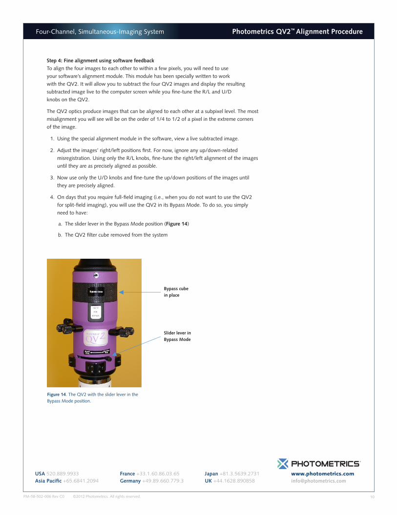
4. On days that you require full-field imaging (i.e., when you do not want to use the QV2
for split-field imaging), you will use the QV2 in its Bypass Mode. To do so, you simply
need to have:
a. The slider lever in the Bypass Mode position (Figure 14)
b. The QV2 filter cube removed from the system
Slider lever in Bypass Mode
Bypass cube in place
Figure 14. The QV2 with the slider lever in the Bypass Mode position.


