Quizbank quiz buzzer
16
Quizbank Buzzer 1 User Manual Author: Midhun P.A QUIZBANK BUZZER September 2013 Design: Midhun P.A [email protected] P. Vignesh Swastik Technologies [email protected] Client: Hala P.J The Quizbank, Muscat Codex, Muscat - Oman
-
Upload
midhun-abraham -
Category
Devices & Hardware
-
view
55 -
download
0
Transcript of Quizbank quiz buzzer
Quizbank Buzzer 1
User Manual Author: Midhun P.A
QUIZBANK
BUZZER
September 2013
Design:
Midhun P.A [email protected]
P. Vignesh Swastik Technologies
Client:
Hala P.J The Quizbank, Muscat Codex, Muscat - Oman

Quizbank Buzzer 2
User Manual Author: Midhun P.A
INDEX
About the system .............................................. 3
Installation ........................................................ 6
Replacing the buzzer alarm ............................. 10
Tests ................................................................ 11
Constraints ...................................................... 13
The system ...................................................... 14
At the shows.. ................................................. 15

Quizbank Buzzer 3
User Manual Author: Midhun P.A
About the system
Control Box:
Fig. 1

Quizbank Buzzer 4
User Manual Author: Midhun P.A
There are two power supply cables for the control box:
1. Input to the transformer, power to drive the
microcontroller.
2. 12V DC input to the relay switch board, power to drive
the LED beacons.
The microcontroller is flashed with a C Program and functions
with 16MHz clock frequency. Multiple switch responses from
teams is received and the fastest response is detected.
12 output ports to the switches are divided into six and are
extended out on either side of the control box with wire
connectors.
12 output ports for Light beacons are also divided into six and are
extended out on either side of the control box connected to the
respective wire connectors.
One connector contains a switch and a light beacon output to one
team.
Fig. 2

Quizbank Buzzer 5
User Manual Author: Midhun P.A
Fig. 3
Inbuilt reset button is provided on the board. It is extended via
the reset output port.
When the system in powered on, it will be in the idle state waiting
for input from the teams via the push switch. Once a Push switch
response is received from a team, the buzzer alarm is switched on
for one second and the Light beacon of the corresponding team
switches on. The Light beacon will be kept on. Only when the
reset switch is pressed, the Light beacon turns off. Then the
system gets back to idle state.
The system caters to any no. of teams. Maximum team count is
12.

Quizbank Buzzer 6
User Manual Author: Midhun P.A
Installation
1. Make sure both the power cords from the control box are not
connected to the mains.
2. Put a 9V battery for the inbuilt buzzer alarm (sticker is provided
in the control box).
3. Connect the push switches and Light beacons to the control
box. Each switches and Light beacons are provided with
connectors.
Fig. 4

Quizbank Buzzer 7
User Manual Author: Midhun P.A
The polarities on the Light beacons are indicated by:
Positive- Red Wire.
Negative- White Wire.
Make sure the polarities match on the control box connectors.
Reversing polarities will damage the Light beacons.
Insert the wires by the following method:
Strip the wire.
Bend the copper edge.
Push the wire to the connector firmly. Tight the screw of the connector.
Make sure to screw on the PVC coating of the wire instead of the copper
leads. And make sure no copper leads are protruding outside the
connectors.
Fig. 5
Quizbank Buzzer 8
User Manual Author: Midhun P.A
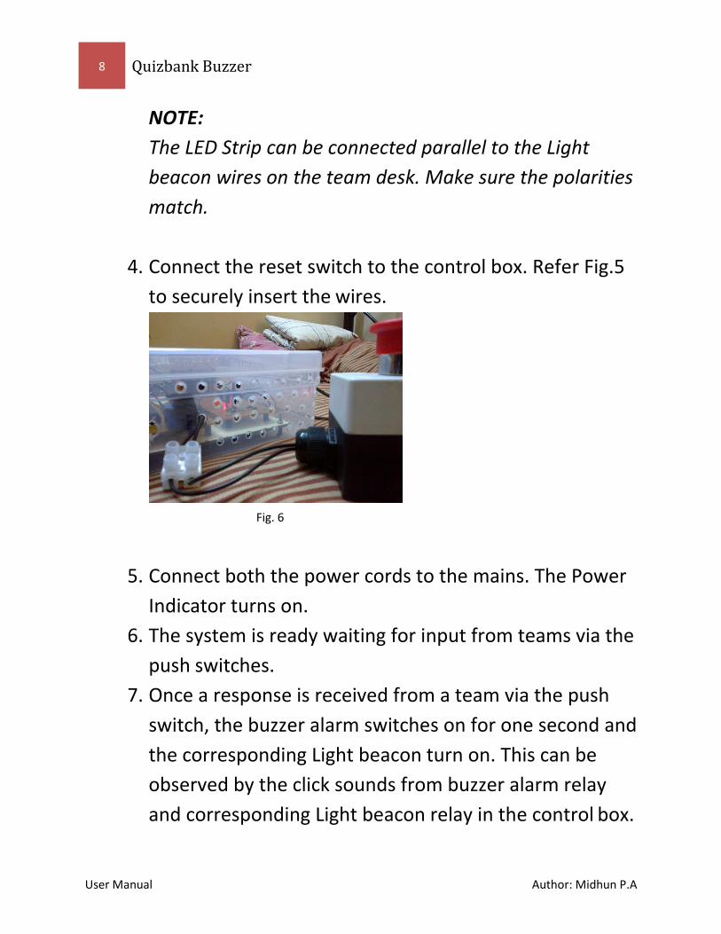
NOTE:
The LED Strip can be connected parallel to the Light
beacon wires on the team desk. Make sure the polarities
match.
4. Connect the reset switch to the control box. Refer Fig.5
to securely insert the wires.
5. Connect both the power cords to the mains. The Power
Indicator turns on.
6. The system is ready waiting for input from teams via the
push switches.
7. Once a response is received from a team via the push
switch, the buzzer alarm switches on for one second and
the corresponding Light beacon turn on. This can be
observed by the click sounds from buzzer alarm relay
and corresponding Light beacon relay in the control box.
Fig. 6

Quizbank Buzzer 9
User Manual Author: Midhun P.A
Also, the corresponding Light beacon relay LED
indicator in the control box turns on. The Light beacon
will be in on state.
8. Push the reset switch to turn off the Light beacon. The
system is reset to idle state waiting for another push
switch response from teams.

User Manual Author: Midhun P.A
Quizbank Buzzer V1.0 10
Replacing the buzzer alarm
NOTE: Make sure the drive voltage of new buzzer alarm is 12V. Since the maximum
Voltage the system function is 12V, higher voltages are risky and might damage
the boards.
As per Fig. 7, connect the inputs of the new buzzer alarm to the
input wires. And connect the power supply wires parallel to the
12V power supply in the control box (brown-positive and blue-
negative wires).
If the new buzzer alarm’s drive voltage is less than 12V, replace
the battery and connect it to the existing power supply wires.
Fig. 7

User Manual Author: Midhun P.A
Quizbank Buzzer V1.0 11
Tests
Test Procedure Observed result Functionality of the microcontroller:
1. Responses of all 12 switch ports.
For the response of each 12 switches, the buzzer alarm turned on for one second and corresponding light relay turned on.
2. Response of reset function.
For the response of each 12 switches, the buzzer alarm turned on for one second and corresponding light relay turned on. When the reset switch was pressed, the light relay turned off.
3. Inbuilt buzzer alarm For the response of each 12 switches, the buzzer alarm turned on for one second and then turned off.
Voltage measured at the connectors.
12 switch ports output: 4.5V(approx.) 12 Light beacon relay output: 12.2V(approx.)
Integration with the purchased Push switches and Light beacons.
The system responded successfully as per the Functionality of the

User Manual Author: Midhun P.A
Quizbank Buzzer V1.0 12
microcontroller.
Stress test The system was kept on for 4 hours.
The system functioned without any faults. The inputs and output response were proper. Since little amount of heat is produced in the power board and transformer, vent holes were provided on the control box.
Distance test A push switch and a Light beacon were kept at 10meters.
The control box responded to the push switch and the light beacon turned on. The voltages observed were same as in Voltage measured at the connectors.
Rigidity of control box. The circuit boards are screwed onto a wooden board. The wooden board is screwed onto the plastic box.
The control box was transported many times. All the screws remained intact and no components were seen loose.
User Manual Author: Midhun P.A
Quizbank Buzzer V1.0 13
Constraints
Has two power supply plugs.
Initially there was one power supply to drive the entire
system. But, it didn’t give sufficient amps to drive 12
light beacons.
So, a dedicated 12V adapter is provided to drive the light
beacons. Also, it gives sufficient power to drive the 12V
LED strip.
Heat is produced from the control box
A mini transformer is used to step down 230V from the
mains. And a power driver circuit board to supply power to
the microcontroller. These will produce a good amount of
heat. Vent holes are provided on the control box.
External buzzer alarm should be 12V
The entire system runs on 12V and 5V(microcontroller).
So, providing a higher volt buzzer alarm to the board is
very risky. It is not sure whether the system will be able to
handle. A 9V buzzer alarm is installed in the control box. It
is sufficient in a huge indoor hall. If the buzzer alarm is to
be replaced refer Replacing the buzzer alarm.
There are 4 wires going from the control box to a team’s
desk
The push switch has two wires. The light beacon also has
two wires (+ and -). When the LED strip is provided, it
will

User Manual Author: Midhun P.A
Quizbank Buzzer V1.0 14
add two more wires. And total will be 6. It is better to connect
the LED strip parallel to the light beacon on the desk.
The system

User Manual Author: Midhun P.A
Quizbank Buzzer V1.0 15
At the shows...
Updated on 29 Jan 2017
X-Quiz-itz 2013
X-Quiz-itz 2013
Inter School Quiz for grade V, VI, VII & VIII students
hosted by the Muscat Codex on 23rd January 2014 at Indian School Muscat.
Inter School Quiz for grade V, VI, VII & VIII students hosted by the Muscat Codex on 23rd January 2014 at
Indian School Muscat.
User Manual Author: Midhun P.A
Quizbank Buzzer V1.0 16
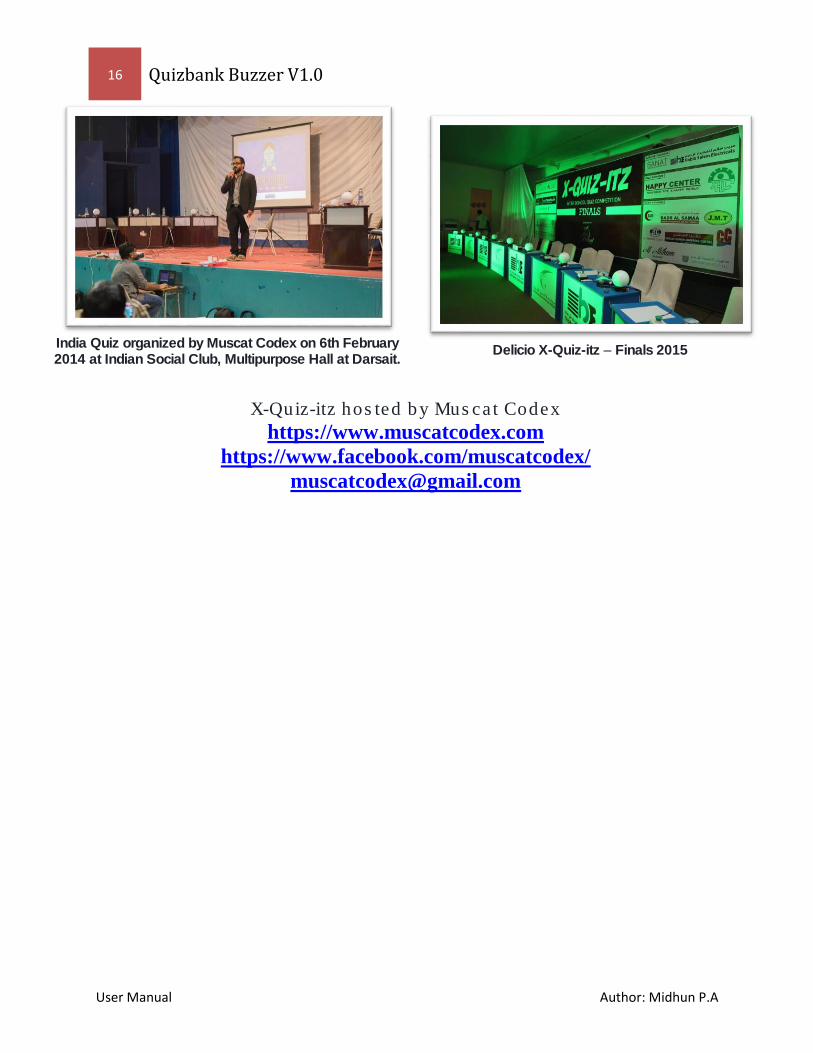
India Quiz organized by Muscat Codex on 6th February 2014 at Indian Social Club, Multipurpose Hall at Darsait.
Delicio X-Quiz-itz – Finals 2015
X-Quiz-itz hosted by Muscat Codex
https://www.muscatcodex.com
https://www.facebook.com/muscatcodex/