Quickstart reference for the software e!COCKPIT
56
Quickstart Reference WAGO Software 2759-0101 Quickstart reference for the software e!COCKPIT Version 2.2.0
Transcript of Quickstart reference for the software e!COCKPIT

Quickstart Reference
WAGO Software
2759-0101 Quickstart reference for the software e!COCKPIT
Version 2.2.0

2 WAGO Software 2759-0101 Quickstart reference for the software e!COCKPIT
Quickstart Reference Version 2.2.0
© 2018 WAGO Kontakttechnik GmbH & Co. KG All rights reserved.
WAGO Kontakttechnik GmbH & Co. KG
Hansastraße 27 D-32423 Minden
Phone: +49 (0) 571/8 87 – 0 Fax: +49 (0) 571/8 87 – 1 69
E-Mail: [email protected]
Web: http://www.wago.com
Technical Support
Phone: +49 (0) 571/8 87 – 5 55 Fax: +49 (0) 571/8 87 – 85 55
E-Mail: [email protected]
Every conceivable measure has been taken to ensure the accuracy and completeness of this documentation. However, as errors can never be fully excluded, we always appreciate any information or suggestions for improving the documentation.
E-Mail: [email protected]
We wish to point out that the software and hardware terms as well as the trademarks of companies used and/or mentioned in the present manual are generally protected by trademark or patent.
WAGO is a registered trademark of WAGO Verwaltungsgesellschaft mbH.

WAGO Software Table of Contents 3 2759-0101 Quickstart reference for the software e!COCKPIT
Quickstart Reference Version 2.2.0
Table of Contents 1 Notes about this Documentation ............................................................. 5 1.1 Scope of Validity ..................................................................................... 5 1.2 Copyright ................................................................................................ 5 1.3 Symbols ................................................................................................. 6 1.4 Number Notation .................................................................................... 8 1.5 Font Conventions ................................................................................... 8
2 Important Notes ........................................................................................ 9 2.1 Legal Bases ............................................................................................ 9 2.1.1 Subject to Changes ............................................................................ 9 2.1.2 Personnel Qualification ...................................................................... 9 2.2 Safety Advice (Precautions) ................................................................. 10
3 Overview .................................................................................................. 11
4 Requirements .......................................................................................... 13 4.1 System Requirements .......................................................................... 13 4.2 Licenses ............................................................................................... 14
5 Installation ............................................................................................... 16 5.1 Installing e!COCKPIT ........................................................................... 16
6 Start ......................................................................................................... 17 6.1 Starting e!COCKPIT ............................................................................. 17 6.2 Purchasing a License ........................................................................... 18 6.3 Activating the License ........................................................................... 18 6.4 Activating Automatic Updates ............................................................... 20
7 Operation ................................................................................................. 21 7.1 Creating a New Project ......................................................................... 21 7.1.1 Overview of the User Interface ......................................................... 21 7.2 Configuration and Parameterization...................................................... 24 7.2.1 Offline Configuration ........................................................................ 24 7.2.1.1 Adding Devices in the Project ...................................................... 24 7.2.2 Online Configuration ........................................................................ 25 7.2.2.1 Scanning the Network and Devices ............................................. 25 7.3 Addressing Inputs/Outputs ................................................................... 30 7.4 Creating a Simple Program .................................................................. 31 7.5 Example: Creating a Simple MODBUS Network ................................... 32
8 The PFC200 Controller............................................................................ 38 8.1 Checking the Firmware Version of the PFC200 Controller .................... 38 8.2 Updating the PFC200 Controller Firmware ........................................... 40 8.3 Entering Settings for the PFC200 Controller ......................................... 42 8.3.1 Obtaining an IP Address via DHCP .................................................. 42 8.3.2 Setting a Fixed IP Address ............................................................... 42 8.3.3 Entering ETHERNET Settings .......................................................... 43 8.3.4 Access via Web-Based-Management (WBM) .................................. 44 8.3.5 Opening a Serial Port Connection .................................................... 49 8.3.6 Establishing an ETHERNET Connection .......................................... 50

4 Table of Contents WAGO Software 2759-0101 Quickstart reference for the software e!COCKPIT
Quickstart Reference Version 2.2.0
8.3.7 Selecting the Runtime Environment ................................................. 50
List of Figures .................................................................................................. 53
List of Tables .................................................................................................... 55

WAGO Software Notes about this Documentation 5 2759-0101 Quickstart reference for the software e!COCKPIT
Quickstart Reference Version 2.2.0
1 Notes about this Documentation
Always retain this documentation! This documentation is part of the product. Therefore, retain the documentation during the entire service life of the product. Pass on the documentation to any subsequent user. In addition, ensure that any supplement to this documentation is included, if necessary.
Note about working with this documentation! Please read the “Overview” section, it is an introduction to the software and provides a general description of functions. The following sections describe program installation and launch. Next, familiarize yourself with the e!COCKPIT graphical user interface. The subsequent sections contain operating instructions for using the software.
</dg_
1.1 Scope of Validity This documentation applies to the “e!COCKPIT” software version 1.4.0.
Observe other applicable documentation! Besides this Quick Start Guide, observe additional instructions and information provided in the operating instructions for the software and devices used. Download the operating instructions for the e!COCKPIT software and PFC200 used from the website http://www.wago.com.
1.2 Copyright
This Manual, including all figures and illustrations, is copyright-protected. Any further use of this Manual by third parties that violate pertinent copyright provisions is prohibited. Reproduction, translation, electronic and phototechnical filing/archiving (e.g., photocopying) as well as any amendments require the written consent of WAGO Kontakttechnik GmbH & Co. KG, Minden, Germany. Non-observance will involve the right to assert damage claims.
6 Notes about this Documentation WAGO Software 2759-0101 Quickstart reference for the software e!COCKPIT
Quickstart Reference Version 2.2.0
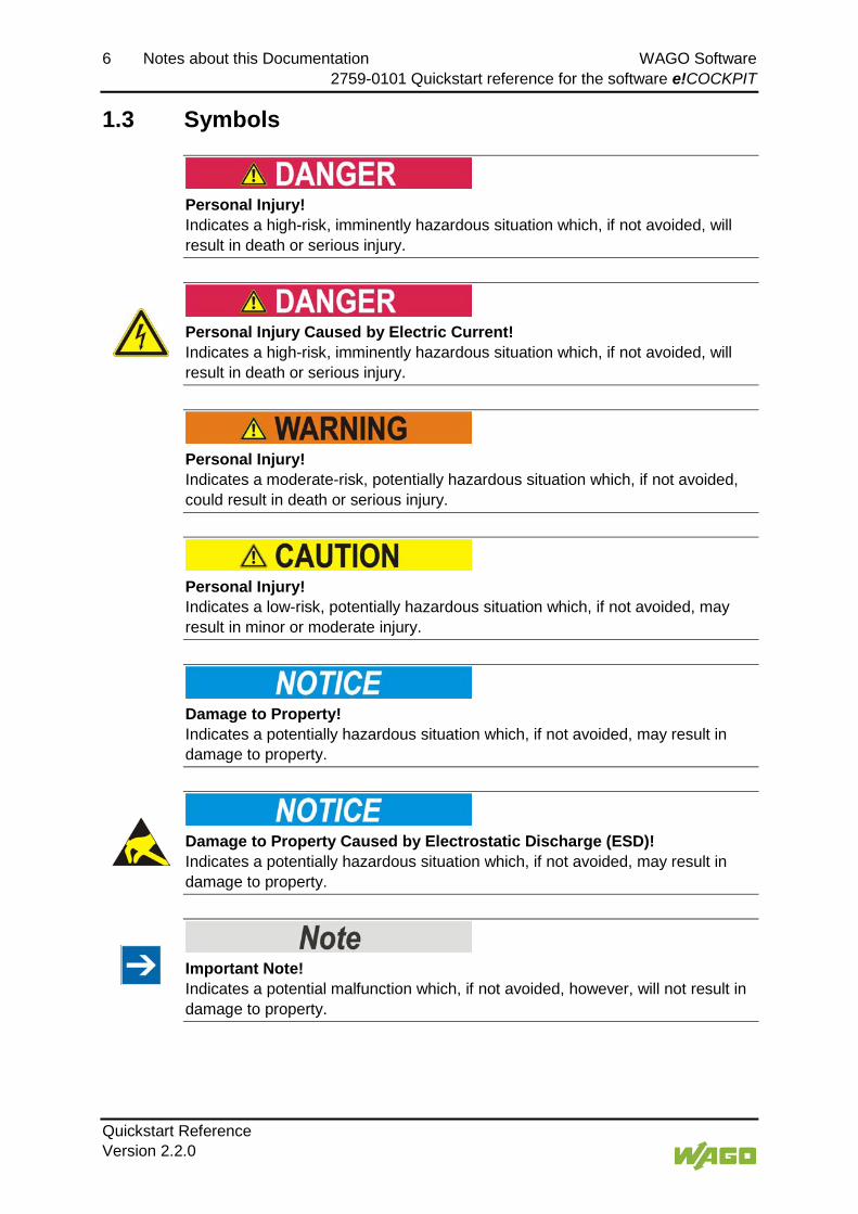
1.3 Symbols
Personal Injury! Indicates a high-risk, imminently hazardous situation which, if not avoided, will result in death or serious injury.
Personal Injury Caused by Electric Current! Indicates a high-risk, imminently hazardous situation which, if not avoided, will result in death or serious injury.
Personal Injury! Indicates a moderate-risk, potentially hazardous situation which, if not avoided, could result in death or serious injury.
Personal Injury! Indicates a low-risk, potentially hazardous situation which, if not avoided, may result in minor or moderate injury.
Damage to Property! Indicates a potentially hazardous situation which, if not avoided, may result in damage to property.
Damage to Property Caused by Electrostatic Discharge (ESD)! Indicates a potentially hazardous situation which, if not avoided, may result in damage to property.
Important Note! Indicates a potential malfunction which, if not avoided, however, will not result in damage to property.

WAGO Software Notes about this Documentation 7 2759-0101 Quickstart reference for the software e!COCKPIT
Quickstart Reference Version 2.2.0
Additional Information: Refers to additional information which is not an integral part of this documentation (e.g., the Internet).

8 Notes about this Documentation WAGO Software 2759-0101 Quickstart reference for the software e!COCKPIT
Quickstart Reference Version 2.2.0
1.4 Number Notation
Table 1: Number Notation Number Code Example Note Decimal 100 Normal notation Hexadecimal 0x64 C notation Binary '100'
'0110.0100' In quotation marks, nibble separated with dots (.)
1.5 Font Conventions
Table 2: Font Conventions Font Type Indicates italic Names of paths and data files are marked in italic-type.
e.g.: C:\Program Files\WAGO Software Menu Menu items are marked in bold letters.
e.g.: Save > A greater-than sign between two names means the selection of a
menu item from a menu. e.g.: File > New
Input Designation of input or optional fields are marked in bold letters, e.g.: Start of measurement range
“Value” Input or selective values are marked in inverted commas. e.g.: Enter the value “4 mA” under Start of measurement range.
[Button] Pushbuttons in dialog boxes are marked with bold letters in square brackets. e.g.: [Input]
[Key] Keys are marked with bold letters in square brackets. e.g.: [F5]

WAGO Software Important Notes 9 2759-0101 Quickstart reference for the software e!COCKPIT
Quickstart Reference Version 2.2.0
2 Important Notes
This section describes the legal principles and system requirements for using the software in compliance with intended purpose, underlying provisions and stated specifications.
2.1 Legal Bases
2.1.1 Subject to Changes
WAGO Kontakttechnik GmbH & Co. KG reserves the right to provide for any alterations or modifications. WAGO Kontakttechnik GmbH & Co. KG owns all rights arising from the granting of patents or from the legal protection of utility patents. Third-party products are always mentioned without any reference to patent rights. Thus, the existence of such rights cannot be excluded.
2.1.2 Personnel Qualification
Any steps related to the use of WAGO software may only be performed by qualified employees with sufficient knowledge of handling the respective PC system used.
Steps in which files are created or changed on the PC system may only be performed by qualified employees with sufficient knowledge in the administration of the PC system used in addition to the aforementioned.
Steps in which the behavior of the PC system in a network is changed may only be performed by qualified employees with sufficient knowledge in the administration of the network used in addition to the aforementioned.

10 Important Notes WAGO Software 2759-0101 Quickstart reference for the software e!COCKPIT
Quickstart Reference Version 2.2.0
2.2 Safety Advice (Precautions)
Use up-to-date security software! Secure operation of the PC system can be at risk as a result of malware such a viruses and Trojans, as well as related threats such as denial-of-service attacks. Therefore, make sure that the latest security software and definitions are always installed on the PC system.
Disable or uninstall software that is no longer required! The vulnerability of a PC system against malware and related threats increases with the number of installed or active software components (applications and services). Therefore, uninstall or disable software components that are not needed for the purpose at hand.
</dg_
Check the runtime system if access problems occur! To access devices from e!COCKPIT, e!RUNTIME must be set in your device as the runtime system. In the event of access problems, check the device settings with your tool (hardware dependent) or from the Web-based management system.
</dg_
Adjust the screen resolution if necessary! The CODESYS programming environment in e!COCKPIT is optimized for a screen resolution of 96 DPI. If editors are displayed out of focus, you may be using a different resolution. To adjust the resolution: 1. Right-click on the desktop. 2. Click Customize. 3. Click Display. 4. Select “100%.”

WAGO Software Overview 11 2759-0101 Quickstart reference for the software e!COCKPIT
Quickstart Reference Version 2.2.0
3 Overview e!COCKPIT is an integrated development environment with seamless data retention for all automation tasks:
• Hardware configuration and parameterization
Hardware component configuration is an essential element of automation applications. All devices are configured so that the controller software produces optimum results during runtime. Controllers, fieldbus couplers/controllers, modules, input and output devices, as well as their communication relations can be configured.
Integrated configurators assist with device and network configuration using standard operating procedures: For example, it is possible to arrange devices in the project via Drag & Drop, use Copy & Paste to quickly multiply individual devices or entire network branches, or set parameter values for multiple devices simultaneously.
Besides the organization of devices in a tree structure, e!COCKPIT also enables the graphical display of a network topology – in the Network view – as a display form. This makes it possible to monitor complex interrelationships between devices and their current statuses. The network topology is likewise used for configuring different communication protocols. e!COCKPIT simplifies connecting controllers to fieldbuses.
Fieldbus-specific device description files (e.g., EDS), device drivers and libraries allow systems from other suppliers to be integrated into the topology along with WAGO devices. As such, the software has information on device specifications, i.e., device data or supported functions.
• Programming with integrated e!RUNTIME
e!COCKPIT integrates the e!RUNTIME programming software that is based on CODESYS 3. This enables software development in the standard IEC 61131-3 programming languages: Structured text (ST), ladder diagram (LD), function block diagram (FBD), sequential function chart (SFC) and “Continuous Function Chart” (CFC). For flexibility, all programming languages can be combined with one another. Created programs can be checked easily via simulations on the development PC. Existing programs can be reused and further developed.
• Visualization (operation and monitoring)
e!COCKPIT uses Drag & Drop to streamline user interfaces for the operation and visualization of a plant. The integrated visualization editor offers direct access to the program's variables in order to simulate the human machine interface (HMI) and PLC program on the PC. Using Unicode and the latest standards, such as HTML 5 or CSS, also prevents dependency on particular languages and target systems.

12 Overview WAGO Software 2759-0101 Quickstart reference for the software e!COCKPIT
Quickstart Reference Version 2.2.0
• Diagnostics for target-oriented development and commissioning
Whether in the office for development or at the machine for commissioning: Knowing the current, detailed status of the automation network is vital in order to obtain, audit and enable rapid fault localization and debugging. e!COCKPIT offers powerful diagnostic options for this purpose: Error messages are displayed immediately. Through the structured wiring test function, erroneous wiring can be systematically identified.
• Other useful functions
e!COCKPIT comes with an extensive range of IEC libraries. The software also offers several convenience functions, such as automatic updates, context-sensitive menus or user-defined workspaces.
References to the e!RUNTIME programming environment! Setting options in e!COCKPIT resulting from the integrated e!RUNTIME and CODESYS programming environment are described in the online help feature. Opening the online help in e!COCKPIT will also display the CODESYS documentation in the tree view next to the e!COCKPIT documentation. Individual setting windows or names within the CODESYS documentation may differ from how they are shown in e!COCKPIT.

WAGO Software Requirements 13 2759-0101 Quickstart reference for the software e!COCKPIT
Quickstart Reference Version 2.2.0
4 Requirements 4.1 System Requirements
Minimum System Requirements
Table 3: Minimum System Requirements Components Requirements Operating System Windows 7/8 Memory 4 GB Free hard disk storage 6 GB Processor Dualcore CPU Screen resolution 1,366 x 768 Pixel
Recommended System Requirements
Table 4: Recommended System Requirements Components Requirements Operating System Windows 7/8/10 x64 Memory 8 GB Free hard disk storage 10 GB Processor Quadcore CPU Screen resolution 1,920 x 1,080 Pixel
Requirements for using a PFC200
Table 5: Requirements for using a PFC200 Firmware Version Requirements 040x0x This controller can be operated without any firmware update. 030x0x Before operation, this controller has to be updated with a new firmware.
PFC200 must have a firmware version > 3! To configure in e!COCKPIT your PFC200 must have a manufacturing firmware version >3. For this note the marking on the housing (see Section “The PFC200 Controller” > “Checking the Version of the PFC200 Controller”). Devices that are marked with firmware version 01 or 02 are not e!COCKPIT-compatible. In this case, perform a firmware update (see Section “Updating Firmware for a PFC200 Controller”).

14 Requirements WAGO Software 2759-0101 Quickstart reference for the software e!COCKPIT
Quickstart Reference Version 2.2.0
4.2 Licenses e!COCKPIT software is protected by licensing mechanisms. Licensing of other software products can also be managed in e!COCKPIT, e.g., e!COCKPIT add-ons.
For productive, unlimited software usage, a license is required. The software can also be used fully without a license key for 30 days. This trial period only includes the days of actual use. When loading the software, a prompt appears with the number of days remaining. Access without a license key is not possible after the trial period.
Depending on the type of software license, an Internet connection may be required for activation. Please refer to your license certificate for the corresponding information.
The following licensing models are defined. Depending on the software, one or more of these licensing models are available:
Single license • 1 license key for 1 PC Workstation license: • 2 license keys for 2 PCs (e.g. PC and laptop) Multi-user license • 5/10/15/20 license keys for 10/15/20 PCs Site license • 1 license key; installations on an unlimited number of PCs at one company
location Buyout license • 1 license key; allows installation on an unlimited number of PCs within a
company. In addition, the software shall be used in the company's products that contain WAGO's automation components and thus form a functional unit (e.g. machines with integrated PC).
Starter kit license • 1 license key for one PC; sale only in conjunction with hardware
Only use the license key according to license conditions! Do not use your license key outside the limits of your license model, otherwise you will be breaking the license agreement, which may have legal consequences.

WAGO Software Requirements 15 2759-0101 Quickstart reference for the software e!COCKPIT
Quickstart Reference Version 2.2.0
Activating a license key is described in section “Starting”.
In addition to the software, certain extensions are subject to license protection (see Section “Enabling Licensed Add-ons”).

16 Installation WAGO Software 2759-0101 Quickstart reference for the software e!COCKPIT
Quickstart Reference Version 2.2.0
5 Installation e!COCKPIT software is installed from a setup file. This contains a CODESYS programming environment, the .NET Framework and communication drivers for WAGO 750 Series devices. The device description files (Device Type Packages) for WAGO 750 Series devices are also automatically imported.
5.1 Installing e!COCKPIT 1. Open the e!COCKPIT Website. 2. To receive a download link for the e!COCKPIT software, click the
[Registration] link and complete the form. 3. Download the software. 4. Start the installation process by double-clicking the setup file and follow the
steps described in the Installation Wizard:
• Select the installation language. • Accept the license agreement. • Select the target directory for installation. 5. Click [Install] to start the installation. If an older version is already installed, a dialog appears in which you can choose to accept already installed devices.
6. Click [Finish] to complete installation.

WAGO Software Start 17 2759-0101 Quickstart reference for the software e!COCKPIT
Quickstart Reference Version 2.2.0
6 Start 6.1 Starting e!COCKPIT
1. Launch e!COCKPIT via Start > Programs > “WAGO Software” > “e!COCKPIT” or via the link on your desktop.
Continue setup after restarting PC! After installation, e!COCKPIT is usually restarted automatically. If installation of e!COCKPIT is not completed, restart e!COCKPIT. If e!COCKPIT is still not available, launch the setup again. If e!COCKPIT crashes the first time you launch it, restart your PC. This can happen if .NET Framework is not installed or an older version is installed on your PC. If you start e!COCKPIT again, use administrator rights.
A start screen will be displayed while the software is loaded.
If you have already purchased and activated a license, the lower area of this screen will display the name under which your e!COCKPIT application is registered.
If you have not yet acquired a license, you can see the remaining time on the start screen.
Figure 1: Display of the Start Screen during Loading
This also opens a dialog via which you can purchase/activate a license (see the following section).
Figure 2: Display of the License Status

18 Start WAGO Software 2759-0101 Quickstart reference for the software e!COCKPIT
Quickstart Reference Version 2.2.0
2. To test e!COCKPIT without entering a license key, click [Continue evaluation].
6.2 Purchasing a License 1. If you wish to purchase a license, click [Purchase license] after launching
the software.
You will be taken to a Website where you can place the order (Online catalogue/ eShop).
6.3 Activating the License When purchasing the software via WAGO Kontakttechnik GmbH & Co. KG, the license key will be sent to you by email or phone.
1. To enter a purchased license key and activate the license, click [Enter license].
Pay attention to exact spelling! Depending on your selected license, an Internet connection may be required for entering and activating the license. Licenses that do not require an Internet connection for activation require the entry of the customer name. Ensure that you enter your customer name exactly as it is written in the email that you received when purchasing the software.
2. Enter your license key and, if necessary, your customer name in the dialog.
Figure 3: Entering the License Key
3. Accept the license conditions and confirm that you are a commercial user.
4. To activate the license, click [Add licenses].

WAGO Software Start 19 2759-0101 Quickstart reference for the software e!COCKPIT
Quickstart Reference Version 2.2.0
If the software has already been launched, open this dialog in the Backstage view: “Licensing” page, [License Manager], [Enter licenses].
Figure 4: Entering Licenses
This creates the license and is displayed in the license manager.
Open an Internet connection to activate licenses! Ensure that an Internet connection is established before you enter a license. The Internet connection is required for checking the validity of a license and for activation. The license is also checked and activated if you tick the “Check for update and license information when starting e!COCKPIT” checkbox in Backstage view, “Help” > [Update].

20 Start WAGO Software 2759-0101 Quickstart reference for the software e!COCKPIT
Quickstart Reference Version 2.2.0
6.4 Activating Automatic Updates After the program is launched, the “Automatic updates” dialog is displayed.
Figure 5: Activating Automatic Updates
1. To automatically search for updates when the program launches, click [Yes].
If you choose [No], you can enable the Update function later: In the Backstage view (“FILE” tab) “Updates & Add-ons” page, tick the “Check for update and license information when starting e!COCKPIT” checkbox (Internet connection required on starting the program).
The update process compares your license information with the records of WAGO Kontakttechnik GmbH & Co. KG.
For additional information on performing updates, see the Section “Operating” > “Setting and Managing” > “Performing Updates”.

WAGO Software Operation 21 2759-0101 Quickstart reference for the software e!COCKPIT
Quickstart Reference Version 2.2.0
7 Operation This section describes software operation through its stages and typical workflows.
7.1 Creating a New Project 1. Launch e!COCKPIT.
2. Select a template in the Start view, e.g., “Empty Project.”
Figure 6: Selecting a Template
This creates a project. The main view is opened.
7.1.1 Overview of the User Interface
The following workspaces are used in general:
• Network/Devices
• Programming
After the project is created, e!COCKPIT first opens with the “Network/Devices” workspace.

22 Operation WAGO Software 2759-0101 Quickstart reference for the software e!COCKPIT
Quickstart Reference Version 2.2.0
Figure 7: “Network/Devices” Workspace
3. Move between the two workspaces by clicking the appropriate icon in the “Device Structure” panel.
Figure 8: Toggling between Workspaces
The “Network/Devices” view provides the following alternative display forms:
• Tabular view
Figure 9: Tabular Network View

WAGO Software Operation 23 2759-0101 Quickstart reference for the software e!COCKPIT
Quickstart Reference Version 2.2.0
• Graphical view
Figure 10: Graphical Network View
4. Move between these views by clicking on the appropriate icons in the main view.
Figure 11: Toggling Between Graphical and Tabular View

24 Operation WAGO Software 2759-0101 Quickstart reference for the software e!COCKPIT
Quickstart Reference Version 2.2.0
7.2 Configuration and Parameterization
7.2.1 Offline Configuration
In offline configuration mode, you configure the devices and network first without connecting to real devices. The configuration is saved and transferred at a later time.
7.2.1.1 Adding Devices in the Project
If there are imported devices in the Product Catalog, they can be used as follows:
• To add devices to a project, drag the individual devices (in this example, a PFC200) from the Product Catalog and drop them onto a free tile in Network view. To place devices on a free tile automatically, double-click the device name.
Figure 12: Dragging Devices to the Network View
• To insert a device several times click the Add symbol next to the device name. In the opened window enter the number of devices you wish to insert and click [Add].
Figure 13: Adding Several Identical Devices
• Open the Device Detail view by double-clicking an appropriate tile. Drag the modules from the product catalog to any position after the head station.

WAGO Software Operation 25 2759-0101 Quickstart reference for the software e!COCKPIT
Quickstart Reference Version 2.2.0
Figure 14: Adding Modules
This will display a [+] next to the mouse pointer. Positioning lines between existing modules indicate at what point the module will be placed when you release the mouse button. Alternatively, the module can also be added by double-clicking it from the Product Catalog behind the currently selected module or at the last location.
The Device detail view only allows the configuration of one head station with connected modules.
7.2.2 Online Configuration
In online configuration mode, you are physically connected to your devices in the network via e!COCKPIT. The configuration can be transferred directly. Click the [Connect] button to connect to available devices directly or perform a network scan first.
7.2.2.1 Scanning the Network and Devices
To display devices present in the network, scan the network first:
1. Click [Network/Devices] in the device/program structure.
2. Open the “NETWORK” tab.
3. If the Network view does not appear in the workspace, click the [Network] button in the menu ribbon.
4. First check the communication settings by selecting from the selection field in the “Scan Settings” group the medium in which the search will be performed, such as ETHERNET.

26 Operation WAGO Software 2759-0101 Quickstart reference for the software e!COCKPIT
Quickstart Reference Version 2.2.0
Figure 15: Selecting the Medium for Scanning
5. Click [Settings] to make other settings.
6. For instance, restrict the scan range for the ETHERNET settings.
Figure 16: Restricting the Scan Range
7. Click [Accept].
8. To search for devices within the specified range, click the [Scan] button in the menu ribbon.
Figure 17: Starting the Scan Operation
After the scan has finished, the search results of the configuration are displayed:
• Green: Configured and scanned device match. • Red: Configured and scanned device are different. • Blue: New device detected (if the device cannot be selected, this is an
unknown device).

WAGO Software Operation 27 2759-0101 Quickstart reference for the software e!COCKPIT
Quickstart Reference Version 2.2.0
Figure 18: Displaying a Scan Result
A red exclamation mark on a device indicates that it is not in the Product Catalog. In this case import the corresponding device description file for this device by importing it (“FILE” tab > [Product Catalog] > [Import device]). Please note that “dtp” file types are always permanently installed and cannot be imported. Use, for example, “eds” type device description files.
If there are devices in the project already (left column “Configuration”), you can rename the devices by double-clicking on the name. Simple renaming in list form is also possible in the tabular Network view.
9. Using the mouse, click [Accept selection] in the menu ribbon to select the devices you want to transfer to your project (right column “Scan result”). Click [Accept all] to transfer all devices.
Scan head stations and I/O modules separately or together! In this example first select only the head stations to be accepted. Scan I/O modules separately (point 13). You can also scan the head stations, including the connected I/O modules, by clicking [All incl. modules] via the small triangle next to the [Accept all] button.
After accepting the scan results ([Accept selection]/[Accept all]) or canceling the scan ([Cancel]/[Close scan results]), the view is automatically closed. The Network view is displayed.
10. To identify the modules of the scanned head station, double-click the device to enter Device Detail view.
11. Click [Scan modules] in the open “DEVICE” tab.
Figure 19: Scanning Modules

28 Operation WAGO Software 2759-0101 Quickstart reference for the software e!COCKPIT
Quickstart Reference Version 2.2.0
If the device is not connected, it is first automatically connected. The modules are then detected. The workspace shows the configuration and scan results. In the right-hand area, all modules which are connected with the device and which have their device description files loaded in e!COCKPIT are displayed.
Figure 20: Displaying Scanned Modules
A device description file can represent several modules if these have the same process data structure. A detected module may also be represented by several device description files. For this reason, there can be selection boxes for certain modules.
12. Select the used module in the selection box.
Figure 21: Selecting Modules
If there are several modules with the same scan result, the “Use for all suitable modules” checkbox is displayed in the selection field. Activate this checkbox to accept the selection for all suitable modules at the same time. The corresponding modules are marked for the transfer.
13. Tick the checkboxes in front of the modules that you wish to add to your project and click [Accept selection]. To transfer all modules, click [Accept all].
Figure 22: Applying Modules
The number of I/O modules detected is displayed in the Network view at the bottom of the device image.
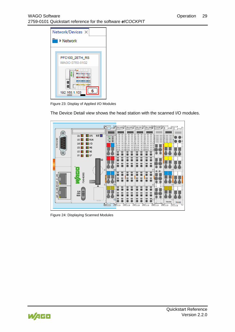
WAGO Software Operation 29 2759-0101 Quickstart reference for the software e!COCKPIT
Quickstart Reference Version 2.2.0
Figure 23: Display of Applied I/O Modules
The Device Detail view shows the head station with the scanned I/O modules.
Figure 24: Displaying Scanned Modules

30 Operation WAGO Software 2759-0101 Quickstart reference for the software e!COCKPIT
Quickstart Reference Version 2.2.0
7.3 Addressing Inputs/Outputs As a CODESYS 3-based system, e!COCKPIT does not have information for the fixed addressing of inputs and outputs customary with CODESYS 2.
Variable names must be assigned to inputs and outputs.
In the Device view, select a module to which you wish to assign variables and enter the variable names in the table underneath it.
Figure 25: Selecting a Module and Assigning Variable Names

WAGO Software Operation 31 2759-0101 Quickstart reference for the software e!COCKPIT
Quickstart Reference Version 2.2.0
7.4 Creating a Simple Program 1. Open the “Programming” workspace.
Figure 26: Opening the “Programming” Workspace
2. Double-click “PLC_PRG” to open the program editor.
Figure 27: Opening the Program Editor
3. Select the configured I/O variables via the Input Assistant by pressing [F2] in the program editor.
Figure 28: Opening Configured Variables in the Program Editor
4. Complete your program.
5. Then load and start your program by right-clicking “Application” and choosing Connect and then Start.
Figure 29: Connecting and Starting an Application

32 Operation WAGO Software 2759-0101 Quickstart reference for the software e!COCKPIT
Quickstart Reference Version 2.2.0
7.5 Example: Creating a Simple MODBUS Network Besides parameterization of individual devices, you can also design complete networks via e!COCKPIT. Select devices from the product catalog, drag them to a Network view, use connectors to connect the devices to each other, assign communication protocols and roles (master/slave) and configure the connection.
1. Select two devices from the Product Catalog and drag them with the mouse into the Network view.
Figure 30: Dragging Devices to the Network View
2. To change the settings or parameters of the devices added, click the respective device, open the “Settings” panel in the context menu and make your changes there.
Figure 31: Opening the “Settings” Panel
3. Now connect the devices. Click the gray connector (ETHERNET/MODBUS) for one of the devices in the Network view and hold down the mouse button.
4. To connect the devices to each other, drag the connection line to the same type connector of the second device. Release the mouse button as soon as a green plus sign appears.
Figure 32: Establishing Network Connections
The devices are connected. The role of the device defines the connection direction. The connection direction is indicated by an arrow and goes from master to slave.

WAGO Software Operation 33 2759-0101 Quickstart reference for the software e!COCKPIT
Quickstart Reference Version 2.2.0
You can change the master and slave device roles later as needed.
5. Click the MODBUS connector of one or both devices.
6. Click [Comm-Relation] in the context menu.
Figure 33: Select Communication Relationship
The current communication relationship is highlighted in blue and displayed first.
7. Select the second entry as needed. In this example, you retain the communication relationship.
You can also specify the connection protocol.
8. Click the [Protocol] button in the context menu of the MODBUS connector.

34 Operation WAGO Software 2759-0101 Quickstart reference for the software e!COCKPIT
Quickstart Reference Version 2.2.0
9. Select the required connection. In this example, select “MODBUS (TCP)”.
The choices depend on the devices used. If your device can be used as a router for off-network devices, “Port forwarding” can also be selected (see Section “Connecting Off-Network Devices (Port Forwarding)”).
You have defined the role of the device and the protocol used for the connection. Below you open the MODBUS interface configurator. Use the interface configurator to define what slave variables should be available on the master.
10. To open the MODBUS interface configurator for the connection, double-click on the device tile of the slave device in the Network view.
The Device Detail view appears. The MODBUS interface configurator is displayed (“MODBUS-Slave” tab).
The figure below shoes the MODBUS interface configurator after opening. No communication variables between the master and slave have been defined yet.
Figure 34: MODBUS interface configurator

WAGO Software Operation 35 2759-0101 Quickstart reference for the software e!COCKPIT
Quickstart Reference Version 2.2.0
The configurator is divided into two columns:
The variables on the master are displayed on the left. The variables available on the slave and used in the slave application are displayed on the right. The tree displays them in a hierarchical view according to the program structure.
Create variables:
1. Right-click “PLC_PRG”.
The context menu opens.
2. Click the button [Create] to add a data point to create a variable in your program “PLC_PRG”.
Figure 35: Creating New Variables on the Slave
Click the new variable to display the settings for MODBUS access to the new variable “newVAR” in the bottom half of the Slave view (“Variable Settings”).
3. Enter settings in this area if you want configure access to this variable via MODBUS (Description, Data Type, Array, Access, MODBUS Address).
The variable is created in the Slave application.
Figure 36: New Variable in the Slave Application
4. Go back to the Network view.
Below you open the MODBUS fieldbus configurator. Mainly connection settings are made here, MODBUS master variables displayed and created.
5. Click the MODBUS connector of one or both connected devices.

36 Operation WAGO Software 2759-0101 Quickstart reference for the software e!COCKPIT
Quickstart Reference Version 2.2.0
6. Open the MODBUS fieldbus configurator by clicking the button [Configurator].
The MODBUS fieldbus configurator for the master opens.
7. Select the slave variable created in the right column.
8. Click [Publish] in the context menu of the variable.
According to the path (namespace) in the slave application, the created slave variable is generated in the master application. It is then available on the master directly.
The variable created on the master (1), the variable on the slave (2), the cycle time for updating the variables via MODBUS (3) and MODBUS access to the variables (4) are displayed.
ReadOnly (RO): Master reads WriteOnly (WO): Master writes ReadWrite (RW): Master reads and writes
Figure 37: New Variable on the Master
9. Open the “Programming” workspace and open the main program of the master.
Figure 38: Opening the Main Program of the Master

WAGO Software Operation 37 2759-0101 Quickstart reference for the software e!COCKPIT
Quickstart Reference Version 2.2.0
In the master application, access to the “newVar” variable as shown in the following figure. Tip: Press the [F2] key to open the Input Assistant for easy variable selection.
Figure 39: Accessing the “newVar” Variable in the Master Application
In this way, a variable (“newVar”) has been declared in the slave application, made accessible via MODBUS and read in the master application.
38 The PFC200 Controller WAGO Software 2759-0101 Quickstart reference for the software e!COCKPIT
Quickstart Reference Version 2.2.0
8 The PFC200 Controller Checking the controller for compatibility and updating it (if necessary) is described below.
Additional Information Please refer to your controller’s manual for additional information.
8.1 Checking the Firmware Version of the PFC200 Controller The PFC200 controllers need the e!RUNTIME runtime environment to interact with the e!COCKPIT software. This runtime environment is currently not yet part of the controller. Depending on the update status of the controller, it is possible to update it with the included firmware. The steps to determine if your controller is compatible with e!COCKPIT are described below.
Controllers with an update status from February 2015 can be updated! PFC200 controllers manufactured before February 2015 with firmware version 01 or 02 cannot be updated.
You can identify the date of manufacture and the firmware version at the time of delivery via the marking on the service flap.
The PFC200 controller is e!COCKPIT-capable if the date of manufacture is 26.02.2015 (0915) or later and is marked as version 030101 or higher.
Table 6: PFC 200 Factory Marking Marking Example Designation XXXXXXXXXX Internal use WWJJ 0915 Week and year of manufacture FwHwFL 030101 Firmware, hardware and firmware loader H1Hn… Internal use

WAGO Software The PFC200 Controller 39 2759-0101 Quickstart reference for the software e!COCKPIT
Quickstart Reference Version 2.2.0
Figure 40: Marking Position
The same information is located on the side marking of the controller as shown in the figure below.
Figure 41: Side Position of the Marking
Example:
A printed manufacturing number 101503030107040415 means:
101503030107040415: produced in week 10/2015
101503030107040415: produced ex works with firmware version 03.

40 The PFC200 Controller WAGO Software 2759-0101 Quickstart reference for the software e!COCKPIT
Quickstart Reference Version 2.2.0
8.2 Updating the PFC200 Controller Firmware The software installation package of e!COCKPIT also includes the current firmware for the PFC200 controller. The firmware is located in the “02_e!RUNTIME” directory.
To import the firmware into the controller, you need an SD card and a tool that saves the firmware file to the SD card. A freeware tool example is “Win32 Disk Imager.” The subsequent steps are based on the use of this freeware tool.
Use a suitable tool for copying the firmware! Use a tool such as “Win32 Disk Imager” to write the firmware file to the memory card. You cannot simply copy the file. Source: http://sourceforge.net/projects/win32diskimager/
Select the correct memory card for the firmware update! Ensure that you use the right memory card for the firmware update, especially when other external storage devices such as a USB memory are connected to your computer. The information on the target memory is then overwritten.
Specific rights required for the firmware update! Because the tools need specific rights for the firmware update, user permissions are queried via the user account control when starting the tool. If necessary start the software by right-clicking the program and selecting “Run as administrator.”
1. Start “Win32 Disk Imager” and select under “Image File” the firmware file “*.img” that you wish to write to the SD card.
2. Select the SD card under “Device.”
3. Click [Write] to write the firmware to the card.
The progress of the copy operation is displayed under “Progress.”
4. Click [Exit] to close the program.

WAGO Software The PFC200 Controller 41 2759-0101 Quickstart reference for the software e!COCKPIT
Quickstart Reference Version 2.2.0
Figure 42: Win32 Disk Imager
5. Switch off the controller.
6. Take the memory card out of the PC or the card reader and insert it into the controller.
7. Switch on the controller.
The controller boots up from the memory card.
Firmware update also executable via Web-Based Management! You can also load the firmware image in the internal memory of the controller. Use the Web-Based Management (WBM) for this. Find the appropriate command on the WBM page “Administration” > “Create Image.”

42 The PFC200 Controller WAGO Software 2759-0101 Quickstart reference for the software e!COCKPIT
Quickstart Reference Version 2.2.0
8.3 Entering Settings for the PFC200 Controller There are various options described below for entering settings on the controller.
8.3.1 Obtaining an IP Address via DHCP
Within the controller’s factory settings, dynamic assignment of the IP address is set for the ETHERNET interface (port X1 and port X2) using “Dynamic Host Configuration Protocol” (DHCP).
8.3.2 Setting a Fixed IP Address
If you are not running any DHCP server on your network, set the IP address manually to reach the controller via ETHERNET. The X1 ETHERNET interface of the controller can be set on the controller to the fixed address “192.168.1.17.”
1. Set the operating mode switch to the STOP position (middle position).
Figure 43: Setting the Operating Mode Switch to the STOP Position
2. Press the Reset button (RST) with a suitable tool for at least 8 seconds.
Figure 44: Pressing the Reset Button
The saving of the IP address is indicated by the “SYS” LED flashing orange. The controller can now be accessed via the fixed IP address “192.168.1.17.” This IP address is valid until the next restart.
You can access the Web-Based Management of the controller via the fixed address and make settings.
The previous IP setting is restored after a restart.
Additional Information Please refer to the controller manual for other options to permanently change the IP address.

WAGO Software The PFC200 Controller 43 2759-0101 Quickstart reference for the software e!COCKPIT
Quickstart Reference Version 2.2.0
8.3.3 Entering ETHERNET Settings
1. Drag a controller from the Product Catalog onto a free tile in the Network view.
2. Open the “Settings” panel (“VIEW” tab > [Settings]).
3. Select the controller.
4. In the first tab of the “Settings” panel set the serial interface used or the IP address (fixed IP address: 192.168.1.17) when using the ETHERNET interface.
Figure 50: Entering the IP Address in the “Settings” Panel

44 The PFC200 Controller WAGO Software 2759-0101 Quickstart reference for the software e!COCKPIT
Quickstart Reference Version 2.2.0
8.3.4 Access via Web-Based-Management (WBM)
Additional settings can be entered on the controller via HTML pages inside the controller, the Web-Based Management (WBM). The fixed IP address “192.168.1.17” is used for the following example (see previous section).
1. Open a browser and enter “http://192.168.1.17” in the address line.
This opens the Web-Based Management.
A login must be completed in order to enter settings. Without a login the menu items are grayed out, and the mouse pointer appears accordingly above the disabled menu items.
Figure 45: Web-Based Management
2. Click the [Login] button at the top right of the window.
3. Enter “Username” and “Password.” Default: Username admin Password wago

WAGO Software The PFC200 Controller 45 2759-0101 Quickstart reference for the software e!COCKPIT
Quickstart Reference Version 2.2.0
Saving ETHERNET settings permanently
The settings for the ETHERNET interface can be saved permanently on the WBM page under “Networking” > “TCP/IP.”
Figure 46: Permanently Saving ETHERNET Settings

46 The PFC200 Controller WAGO Software 2759-0101 Quickstart reference for the software e!COCKPIT
Quickstart Reference Version 2.2.0
Activating/deactivating protocols
Activate/deactivate unencrypted protocols such as HTTP, FTP or Telnet on the WBM page “Ports and Services – Network Services.”
Figure 47: Activating/Deactivating Protocols

WAGO Software The PFC200 Controller 47 2759-0101 Quickstart reference for the software e!COCKPIT
Quickstart Reference Version 2.2.0
Activate/deactivate authentication for e!RUNTIME and web server
You can change the access data and password for e!RUNTIME at “Ports and Services” > “PLC Runtime Services” (“General Configuration”) or activate/deactivate them (“Port Authentication enabled”). This access data is required when you log into the device when programming in e!COCKPIT.
If you wish to use the web visualization, you can also activate the e!RUNTIME web server on this page (“Webserver enabled”). The web server is deactivated by default.
Figure 55: Activating/Deactivating Authentication for e!RUNTIME and Web Server

48 The PFC200 Controller WAGO Software 2759-0101 Quickstart reference for the software e!COCKPIT
Quickstart Reference Version 2.2.0
Web-Visu
The web visualization can be accessed at “PLC Runtime > Web-Visu” via the Open WebVisu in new window] button or by entering: http:// <IP Address>/webvisu/webvisu.htm.
Figure 48: Calling Web Visualization

WAGO Software The PFC200 Controller 49 2759-0101 Quickstart reference for the software e!COCKPIT
Quickstart Reference Version 2.2.0
8.3.5 Opening a Serial Port Connection
The serial port (also called WAGO Service Interface) is located under the service flap on the controller (this is not the RS 232-485 interface X3 on the controller).
Figure 49: WAGO Service Interface
You need a WAGO USB communication cable (750-923) to connect via the controller’s WAGO service interface.
Additional Information For more information about the WAGO communication cable (WAGO USB Service Cable) refer to the appropriate data sheet (http://www.wago.com > Search “750-923 Communication Cable”).
1. To set the controller in e!COCKPIT via the serial port, select the appropriate interface in the “NETWORK” tab.
Figure 50: Selecting an Interface

50 The PFC200 Controller WAGO Software 2759-0101 Quickstart reference for the software e!COCKPIT
Quickstart Reference Version 2.2.0
8.3.6 Establishing an ETHERNET Connection
1. Open the “NETWORK” tab.
2. In the drop-down menu select the preferred connection. For the ETHERNET connection use a standard ETHERNET cable.
Figure 51: Selecting the “ETHERNET” Interface
8.3.7 Selecting the Runtime Environment
The runtime system can be set or changed via WAGO-ETHERNET Settings or via the Web-Based Management.
Setting the runtime system via WAGO-ETHERNET Settings
1. Click the [Settings] button in the first tab of the “Settings” panel.
Figure 52: Entering Settings
2. This opens WAGO ETHERNET Settings.
The connection is established between WAGO-ETHERNET Settings and the controller. The “Identification” tab displays device data.

WAGO Software The PFC200 Controller 51 2759-0101 Quickstart reference for the software e!COCKPIT
Quickstart Reference Version 2.2.0
3. Open the “PLC” tab.
4. Change the PLC runtime environment to the “e!RUNTIME” programming software used inside “e!COCKPIT.” The runtime environment is set by default to “CODESYS V2.”
Figure 52: Setting Runtime Environments (WAGO Ethernet Settings)
Setting the runtime system via Web-Based Management
1. Open the Web-Based Management System.
2. Log in.
3. Open “PLC Runtime” > “General Configurations.”
4. Change the PLC runtime environment to the “e!RUNTIME” programming software used inside “e!COCKPIT.”

52 The PFC200 Controller WAGO Software 2759-0101 Quickstart reference for the software e!COCKPIT
Quickstart Reference Version 2.2.0
Figure 53: Setting the Runtime Environment (WBM)

WAGO Software List of Figures 53 2759-0101 Quickstart reference for the software e!COCKPIT
Quickstart Reference Version 2.2.0
List of Figures Figure 1: Display of the Start Screen during Loading..........................................17 Figure 2: Display of the License Status ..............................................................17 Figure 3: Entering the License Key .....................................................................18 Figure 4: Entering Licenses ................................................................................19 Figure 5: Activating Automatic Updates ..............................................................20 Figure 6: Selecting a Template ...........................................................................21 Figure 7: “Network/Devices” Workspace ............................................................22 Figure 8: Toggling between Workspaces............................................................22 Figure 9: Tabular Network View ........................................................................22 Figure 10: Graphical Network View ....................................................................23 Figure 11: Toggling Between Graphical and Tabular View .................................23 Figure 12: Dragging Devices to the Network View ..............................................24 Figure 13: Adding Several Identical Devices ......................................................24 Figure 14: Adding Modules ................................................................................25 Figure 15: Selecting the Medium for Scanning ...................................................26 Figure 16: Restricting the Scan Range ...............................................................26 Figure 17: Starting the Scan Operation ..............................................................26 Figure 18: Displaying a Scan Result ...................................................................27 Figure 19: Scanning Modules .............................................................................27 Figure 20: Displaying Scanned Modules ............................................................28 Figure 21: Selecting Modules .............................................................................28 Figure 22: Applying Modules ..............................................................................28 Figure 23: Display of Applied I/O Modules ..........................................................29 Figure 24: Displaying Scanned Modules ............................................................29 Figure 25: Selecting a Module and Assigning Variable Names ...........................30 Figure 26: Opening the “Programming” Workspace ...........................................31 Figure 27: Opening the Program Editor ..............................................................31 Figure 28: Opening Configured Variables in the Program Editor ........................31 Figure 29: Connecting and Starting an Application .............................................31 Figure 30: Dragging Devices to the Network View ..............................................32 Figure 31: Opening the “Settings” Panel ............................................................32 Figure 32: Establishing Network Connections ....................................................32 Figure 33: Select Communication Relationship ..................................................33 Figure 34: MODBUS interface configurator ........................................................34 Figure 35: Creating New Variables on the Slave ................................................35 Figure 36: New Variable in the Slave Application ...............................................35 Figure 37: New Variable on the Master ..............................................................36 Figure 38: Opening the Main Program of the Master ..........................................36 Figure 39: Accessing the “newVar” Variable in the Master Application ...............37 Figure 40: Marking Position ................................................................................39 Figure 41: Side Position of the Marking ..............................................................39 Figure 42: Win32 Disk Imager ............................................................................41 Figure 43: Setting the Operating Mode Switch to the STOP Position .................42 Figure 44: Pressing the Reset Button .................................................................42 Figure 45: Web-Based Management ..................................................................44 Figure 46: Permanently Saving ETHERNET Settings.........................................45 Figure 47: Activating/Deactivating Protocols ......................................................46

54 List of Figures WAGO Software 2759-0101 Quickstart reference for the software e!COCKPIT
Quickstart Reference Version 2.2.0
Figure 48: Calling Web Visualization ..................................................................48 Figure 49: WAGO Service Interface ...................................................................49 Figure 50: Selecting an Interface ........................................................................49 Figure 51: Selecting the “ETHERNET” Interface ................................................50 Figure 52: Entering Settings ...............................................................................50

WAGO Software List of Tables 55 2759-0101 Quickstart reference for the software e!COCKPIT
Quickstart Reference Version 2.2.0
List of Tables Table 1: Number Notation ................................................................................... 8 Table 2: Font Conventions .................................................................................. 8 Table 3: Minimum System Requirements ...........................................................13 Table 4: Recommended System Requirements .................................................13 Table 5: Requirements for using a PFC200 ........................................................13 Table 6: PFC 200 Factory Marking ....................................................................38

WAGO Kontakttechnik GmbH & Co. KG Postfach 2880 • 32385 Minden Hansastraße 27 • 32423 Minden Phone: 0571/887 – 0 Fax: 0571/887 – 169 E-Mail: [email protected] Internet: http://www.wago.com