QuickStart - IMS Software, Inc. · IMSpost Quickstart 2 IMS Dialog Boxes ... function. Default...
64
IMSpost Quickstart i
Transcript of QuickStart - IMS Software, Inc. · IMSpost Quickstart 2 IMS Dialog Boxes ... function. Default...

IMSpost Quickstart
i

IMSpost Quickstart
ii

IMSpost Quickstart
iii
QuickStart Guide This guide will show the steps required to create a postprocessor utilizing the standard IMSpost™ controller files and the IMSmodel™ machine configuration files. This guide provides an initial overview of standard development of a postprocessor. Each explanation is followed by a task to be accomplished following the Lets Do It! statement. This Quickstart Guide is to introduce IMSpost users to the method of defining a postprocessor and is not intended to replace training. Consult the IMSpost™ Users Guide for additional information on the various sections for development of a postprocessor. The intention of this guide is not to introduce or create macro programming, but utilize IMSpost™ standards. Macro programming courses are available and can be scheduled by contacting your IMS Dealer.

IMSpost Quickstart
iv

IMSpost Quickstart
I
Table of Contents WINDOW ENVIRONMENT .................................................................1
IMS WINDOW INTERFACE ...................................................................1 IMS DIALOG BOXES..........................................................................2 DIALOG BOX DEFINITION .................................................................3 STARTING THE IMSPOST INTERFACE ENVIRONMENT....................4 CREATION OF THE IMSPOST PROCESSOR .....................................5 EXPLANATION OF SELECT POSTPROCESSOR DIALOG BOX..........6
USE DEFAULT MACHINE DESCRIPTION ...................................................6 NEW MACHINE DESCRIPTION ..........................................................7
SELECT NEW MACHINE DESCRIPTION.....................................................8 CUSTOMIZE THE POST PROCESSOR ..............................................9
IMSPOST CHECKLIST.........................................................................9 START OF PROGRAM .....................................................................10 PARTNO DEFINITION......................................................................11 TEST COMMANDS – PROGRAM, PART NO............................................12
TEST COMMANDS - COMPLETED ........................................................13 COOLANT DEFINITION....................................................................14 TEST COMMANDS – COOLANT DEFINITION ..........................................15
TEST COMMANDS - COMPLETED ........................................................16 SPINDLE DEFINITION......................................................................17 REGISTER DEFINITION ...................................................................18 TOOL CHANGE ...............................................................................19
TOOL CHANGE – TOOL DEFINITION.....................................................19 TOOL CHANGE – TOOL DEFINITION.....................................................20 TOOL CHANGE – DATA OPTIONS ........................................................21 TOOL CHANGE – BEFORE/AFTER OUTPUT ...........................................22
TEST COMMANDS – PROGRAM, PART NO, COOLANT, SPINDLE, TOOL CHG 23 FEEDRATE DEFINITION ..................................................................24 CUTTER COMPENSATION ..............................................................25 MOTION FUNCTIONS ......................................................................26
MOTION FUNCTION DATA TABS..........................................................26

IMSpost Quickstart
II
MOTION FUNCTIONS – RAPID/FROM ...................................................27 EXPLANATION OF RAPID/FROM DIALOG BOX ........................................27
Motion Functions - Rapid Area ....................................................28 Motion Functions - From Area .....................................................29
TEST COMMANDS – LOAD TOOL ............................................................30 Test Commands - Completed .....................................................31
IMPORTANT QUICKSTART CHANGE TO CHECKLIST.....................32 MOTION FUNCTIONS - LINEAR............................................................32 MOTION FUNCTIONS - LINEAR............................................................33
Explanation of Linear Dialog Box ................................................33 MOTION FUNCTIONS - CIRCLE ...........................................................34
Explanation of Circle Dialog Box – Radius format .........................34 Motion Functions - Circle - Test Commands.................................34 Motion Functions - Circle - Test Commands.................................35 Radius Format – Absolute center coordinates ..............................36 Radius Format – Distance from start to center .............................37 Radius Format – Distance from center to start .............................37 Radius Format – Distance from center to start .............................38 Radius Format – Unsigned distance from center to start ...............38 Radius Format – Unsigned distance from center to start ...............39 Radius Format – Circle radius .....................................................39 Radius Format – Circle radius .....................................................40 Radius Format – Linear moves ...................................................40 Radius Format – Linear moves ...................................................41
MOTION FUNCTION - NURBS..............................................................41 MOTION FUNCTION - NURBS..............................................................42
Explanation of Nurbs Dialog Box .................................................42 MOTION FUNCTIONS – ARC-F IT .........................................................43
Explanation of Arc-Fit Dialog Box ................................................43 MOTION FUNCTIONS – LINE-F IT .........................................................44
Explanation of Line-Fit Dialog Box ...............................................44 DRILL CYCLES ................................................................................45 END OF PROGRAMS.......................................................................46 PROGRAM CODES - SAVE PROJECT FILE ....................................47
IMSPOST CHECKLIST STATUS ............................................................47 CONTINUE CUSTOMIZING THE POST PROCESSOR ......................48
CONTROLLER FORMAT .....................................................................48 SEQUENCE NUMBERS ...................................................................48 SEQUENCE NUMBERS ...................................................................49 COMMENT BLOCKS ........................................................................50 REGISTER FORMAT........................................................................51

IMSpost Quickstart
III
SORT OUTPUT................................................................................51 SORT OUTPUT................................................................................52 TEST COMMANDS – SEQUENCE BLOCKS, SORT OUTPUT........................53 TAPE FORMAT................................................................................54 POSTPROCESS ..............................................................................55 POSTPROCESSOR – TEXT FILE OUTPUT ......................................56


IMSpost Quickstart
1
Window Environment
IMS Window Interface The IMSpost uses a Windows interface for the creation of the postprocessor. This guide will introduce a few Icon and Pull-down Toolbar definitions to get you started. IMS instructional training will expand on the use and purpose of additional Icon and Pull-down toolbar options.
Pull-down menu bar
Icon tool bar
Window banner with filename
Toolbar definition
IMS Window Interface

IMSpost Quickstart
2
IMS Dialog Boxes Standard postprocessor functions can be customized through dialog boxes. Dialog boxes are launched by selecting the desired task from the menus, the toolbars, or the checklist. Most dialog boxes have an OK or Cancel to complete the task.
Part Number Dialog Box Initiated by the IMSpost Checklist
IMS Checklist and Dialog Box

IMSpost Quickstart
3
Dialog Box Definition The dialog box defines the choices or options for the specific postprocessor function.
Radio buttons
Check box
Confirm choices or Cancels choices dispostion
Default input
Pull-down list
Optional input
On-line documentation

IMSpost Quickstart
4
Starting the IMSpost Interface Environment This is your opportunity to start a post processor - Lets Do It! 1. Select Start Icon ↓ 2. Select Program ↓
3. Select IMSpost 70↓ 4. Select IMSpost
5. The execution of the program IMSpost will display the IMS Window Interface.
2
1
3 70 4

IMSpost Quickstart
5
Creation of the IMSpost Processor Default machine description.
The first step to create a postprocessor is the selection a default machine description - Lets Do It! 1. Select File from toolbar ↓
2. Select New from pulldown. 3. Displays Select Postprocessor dialog box. 4. Select milling.def from listing. 5. Select OK standard post is loaded.
1
2
4
1 3 5 3

IMSpost Quickstart
6
Explanation of Select Postprocessor Dialog Box
Use default machine description This example uses milling.def from the Postprocessor Listing.
Execution of dialog box: 1. Activates default parameters 2. Displays IMSpost Checklist
Note:
Controller and Model Number determine default filename. Select OK to load postprocessor parameters.
The project file saves as any windows file. - Save or Save As…
List of library posts
Description of selected postprocessor
Project File – complete description of parameters defines filename with extension .prj
Default parameters of machine selected or new machine format requirements
Sample output from this library postprocessor

IMSpost Quickstart
7
New Machine Description Standard library files do not support multi-axis machines. Various machine configurations are available by selecting a new machine description. Lets Do It! This is similar to a previous selection of a new machine description.
1. Select File from toolbar ↓ 2. Select New from pulldown. 3. Displays Select Postprocessor dialog box. 4. Select milling.def from listing. 5. Identify the radio button Select new machine description 6. Select OK standard post is loaded.
3
1
2
4
6
5
IMSpost Quickstart
8
Select new machine description Select machine dialog box display various machine configurations.The dialog box has two portions: Selection Tree Machine configuration Lets Do It!
1. Open selection tree to define machine. Select plus sign to open each level or minus sign to close:
Milling → Vertical → 4-axis → C-table 2. Observe the change in machine configuration. 3. Complete the selection with Load Machine.
The IMSpost will link the machine configuration with a standard controller file. The IMSpost Checklist will be displayed allowing custom modifications to occur. The Quickstart Guide will introduce the Program Codes from the IMSpost Checklist to get you started with a 3-axis description. The definition of multi-axis will require an expanded use of the IMSpost Checklist that includes motion axes, machine comments and reference points. Additional training instruction is available to satisfy the multi-axis description.

IMSpost Quickstart
9
Customize the post processor Customizing the post processor is achieved by displaying the IMSpost Checklist, identify a parameter value and executing change. Currently you have an unsaved project filed named milling_def.prj.
IMSpost Checklist The IMSpost Checklist is a sheet of steps suggesting a set of tasks necessary to complete the postprocessor
The checklist define three categories • Program Codes – predefined parameters • Controller Format - predefined parameters • Machine Format - predefined parameters
First column of checkmarks indicates assigned parameter values. Optional Choice: Double click checkmark to remove checkmark; a parameter change will redisplay the checkmark, a visual verification.
Modifications will occur on the Program Codes on the proceeding pages. Remove checkmarks to better identify changes using the Quickstart Guide. Lets Do It! Remove all checkmarks from Program Codes Category.
Checkmarks removed After
Default IMSpost Checklist Before

IMSpost Quickstart
10
Start of Program The start of program dialog controls what codes are output at the start of every program. These codes typically set up the initial state of the machine – what units to use, initial locations, absolute or incremental mode, etc. Lets Do It!
1. Double click Start of Program in checklist. 2. Dialog box appears with default parameters. 3. Edit text as shown in dialog box, no spaces required.
Multiple lines are allowed. 4. Select OK – Red checkmark will appear in checklist.
Note: Codes can be formatted according to Number Formats, Sort Order,
Upper/Lower Case and more…. Adding double quotes to the start and end of line will cause the line to output exactly as is. No number formatting, sorting, or any other conversions will be applied.
“G17G20G40” “G49G54G80” “G90G94G98”
1
2
3 3
4
IMSpost Quickstart
11
Partno Definition The partnumber definition dialog provides control over part number processor when postprocessing files. Part numbers can be read from the input file, input by the operator, or ignored Dialog box has two areas:
A. Part Number Options – prompt or no prompt sequence (see below). o Take no action involving part number, no prompt. o Process part number as APT statement or no action taken. o Process part number as APT statement or prompts for value. o Will prompt for part number, even with APT statement.
B. Relationship of values associated with part number Lets Do It!
1. Double click Partno Definition in checklist. 2. Identify prefix string input, type Quickstart . 3. Identify part number pull down, select A. 4. Identify default part number value, edit to 100. 5. Select OK – Red checkmark will appear in checklist.
1
A 3
5
B
Default parameters
2 3
4
IMSpost Quickstart
12
Test Commands – Program, Part No On-line testing. This will allow a test of parameter changes without executing the entire program. This test is to verify the program start and part name choices. This page will setup the input within Text Command dialog box. The output result is displayed on the following page. Lets Do It! 1. Select Execute from pulldown. 2. Select Test Commands.
3. Displays Test Commands dialog box Identify input block, type GOTO/100,200,350. 4. Verify input data type – General APT is default,
otherwise change CAM system. 5. Select Go. 6. Displays dialog box, due to prompt request.
Observe number equals prior input. Select Continue , result on following page.
The result is shown on following page.
Input Block
Output Block
2
3
4
6
1
5
IMSpost Quickstart
13
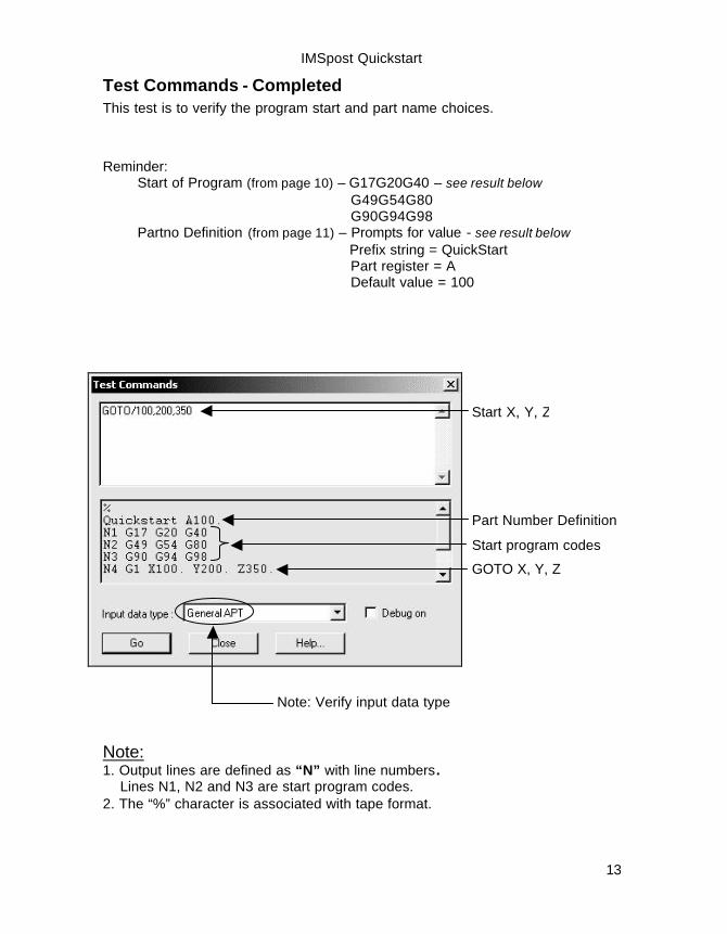
Test Commands - Completed This test is to verify the program start and part name choices.
Reminder: Start of Program (from page 10) – G17G20G40 – see result below G49G54G80 G90G94G98 Partno Definition (from page 11) – Prompts for value - see result below Prefix string = QuickStart Part register = A Default value = 100
Note: 1. Output lines are defined as “N” with line numbers. Lines N1, N2 and N3 are start program codes. 2. The “%” character is associated with tape format.
Part Number Definition
Start program codes
Start X, Y, Z
GOTO X, Y, Z
Note: Verify input data type

IMSpost Quickstart
14
Coolant Definition The coolant definition dialog defines the codes for controlling the various coolant operations (mist, flood, thru, air, off). Lets Do It!
1. Double click Coolant Definition in checklist. 2. Dialog box appears with default parameters. 3. Identify mist coolant, edit to M8@MIST (see special note). 4. Identify mist coolant, edit to M8@FLOOD (see special note). 5. Select OK – Red checkmark will appear in checklist.
Default Parameters
4 3
3
Coolant Code Notes: M9 – coolant off M7 – coolant mist M8 – coolant flood Special Note: Different code must be used for different functions. However, the @ character will allow same code for different functions. Output will be before the @ character, M8@MIST.
1
53
2 3

IMSpost Quickstart
15
Test Commands – Coolant Definition On-line testing. This will allow a test of parameter changes without executing the entire program. This test is to verify the @ usage in the coolant definition. This page will setup the input within Text Command dialog box. The output result is displayed on the following page. Lets Do It! 1. Select Execute from pulldown. 2. Select Test Commands.
3. Displays Test Commands dialog box Identify input block, type COOLANT/MIST GOTO/1,2,3 COOLANT/OFF 4. Verify input data type – General APT is default,
otherwise change CAM system. 5. Select Go. 6. Displays dialog box, due to prompt request.
Observe number equals prior input. Select Continue , result on following page.
The result is shown on following page.
Input Block
Output Block
2
3
4
6
1
5

IMSpost Quickstart
16
Test Commands - Completed This test is to verify the @ usage in the coolant definition..
Reminder: Coolant Definition (from page 15) – COOLNT/MIST GOTO/1,2,3 COOLNT/OFF
Note: Output lines are defined as “N” with line numbers. Lines N1, N2 and N3 are start program codes.
Lines N4 and N5 are associated with coolant definition.
Mist Off
Start X, Y, Z and Mist On
Note: Verify input data type

IMSpost Quickstart
17
Spindle Definition The spindle definition dialog defines the codes used to control the spindle, and the default value for spindle speed. Lets Do It!
1. Double click Spindle Definition in checklist. 2. Dialog box appears with default parameters. 3. Identify spindle speed register, S (register definition on next page). 4. Select OK – Red checkmark will appear in checklist.
Registers contain lines of control parameters. Lines are associated with a register character (S, G, X, N, F…)
Control parameters – specify number format – decimal output – startup values, etc.
Letter S Register – Header definitions on page 18
Default parameters
1 3
S CONST UNIT 0.000000 5.0
3 3
4 3
2

IMSpost Quickstart
18
Register Definition
= OFF = ON
Name Displays the output name of the register. Units Out Displays the output units (INCH, MM, DEG, CONST).
This parameter does not affect the output format except in the case of rotary axis registers.
Units In Displays the input units (INCH, MM, DEG, CONST). Initial Value Displays the initial value of the register. Digits Specifies the number of digits output before and after the
decimal point. For example, 2.4 means output two places to the left and four places to the right of the decimal.
Dec Indicates whether a decimal point is required. Lead Indicates whether there will be leading zero output. Deselect the
checkbox to suppress leading zeros. Trail Indicates whether there will be training zero output. Deselect the
checkbox to suppress trailing zeros. Sign Indicates whether to include a "+" sign before positive values. Modal Indicates whether the register is modal or nonmodal. Incr Indicates whether the register is incremental. Deselect the
checkbox for absolute.
S CONST UNIT 0.000000 5.0
Name Units Units Initial Digits Dec Lead Trail Sign Modal Incr Out In Value

IMSpost Quickstart
19
Tool Change The tool change dialog provides a number of options for defining codes used for tool change operations, and functions that occur when tools are changed. In addition, the operator may provide additional codes before or after the first, and subsequent tool changes. Lets Do It!
1. Double click Tool Change in checklist. 2. Dialog box appears with default parameters.
Dialog box defines three sections A. Tool Definition B. Data Options C. Before/After Output
1
A 3
B
T CONST UNIT 0.000000 4.0
C
2
Registers contain lines of control parameters. Lines are associated with a register character (T, G, X, N, F…)
Control parameters – specify number format – decimal output – startup values, etc.
Letter T Register – Header definition on page 18

IMSpost Quickstart
20
Tool Change – Tool Definition Customize the tool change output for your postprocessor. Parameters choices. Auto tool change function Tool number register Length compensation register Time (mins) to change tools Lets Do It!
1. Verify or change tool definitions as shown.
A 3
Default parameters
Portion of Tool Change
1 3

IMSpost Quickstart
21
Tool Change – Data Options Customize the tool change output for your postprocessor. Parameters choices.
Lets Do It! 1. Dialog box appears with default parameters. 2. Identify parameter changes:
B3
Default parameters
Portion of Data Options
2
1 3

IMSpost Quickstart
22
Tool Change – Before/After Output Customize the tool change output for your postprocessor.
Parameters choices.
Lets Do It 1. Dialog box appears with default parameters. 2. Identify first tool and other tools output values.
C3
Portion of Before/After Output
1 Default parameters
2

IMSpost Quickstart
23
Test Commands – Program, Part No, Coolant, Spindle, Tool Chg
On-line testing of parameter changes without executing the entire program. Lets Do It! 1. Select Execute from pulldown. 2. Select Test Commands.
3. Displays Test Commands dialog box Edit input block as shown, no spaces required. 4. Verify input data type – General APT. 5. Select Go. 6. Displays dialog prompt, select Continue .
7. Output block displays result.
% Quickstart A100. ←Partno Definition N1 G17 G20 G40 N2 G49 G54 G80 ←Start program codes N3 G90 G94 G98 N4 G1 X100. Y200. Z350. T0005 ←go to position x y z, tool register N5 X110. Y21.5 Z47.375 M8←position flood coolant N6 G28 G91 X Y ←incremental output before tool change N7 M5 ←spindle off N8 M9 ←coolant off N9 T0005 M6 ←tool register, tool change N10 G90 G55 ←output after tool change N11 G0 X100. Y120. ←go to position x y plane N12 G43 Z250. H11←cut length, depth, length register N13 G1 Z200. F1500 . ←linear position, feedrate register and value N14 M30 ←machine rewind %
GOTO/100,200,350 COOLNT/FLOOD GOTO/110,21.5,47.375 LOADTL/5,OSETNO,11 GOTO/100,120,250 FEDRAT/MMPM,1500 GOTO/100,120,200
3
Output Block
4 5
7

IMSpost Quickstart
24
Feedrate Definition The federate definition dialog controls the codes used for feedrate output, and formatting options for various feedrate types. Lets Do It!
1. Double click Feedrate Definition in checklist. 2. Dialog box appears with default parameters. 3. Identify Feed per minute:, edit to:
Function G94 Format (mm) 5.3 Format (inch) 4.4 4. Identify Feed per revolution:, edit to:
Function G95 Format (mm) 3.3 Format (inch) 2.4 5. Select OK – Red checkmark will appear in checklist.
1
3 4
Feedrate Note: o Enter the feederate only for the related
machine specifying INCH and MM output. o Format values – number to the left are
integer places, number to the right are decimal places (2.3= 00.000).
o The feedrate register value (F) in this dialog box supercedes Register Format definition.
5

IMSpost Quickstart
25
Cutter Compensation The cutter compensation dialog defines the codes for outputting cutter compensation commands, and the register for the compensation value. Lets Do It!
1. Double click Cutter Compensation in checklist. 2. Dialog box appears with default parameters. 3. Select OK – Red checkmark will appear in checklist.
No modification required.
1
3
Default parameters
2

IMSpost Quickstart
26
Motion Functions The motion functions dialog has several tabs which control the output of various motion types (lines, arcs/circles, and curves). Support is provided for different output formats for arcs and circles; support for NURBS output is also included. Options for line and arc fitting (including restricting arcs to certain planes) for reduced file size and improved surface finish are also available. Double click Motion Functions from IMSpost Checklist. The following pages will identify motion function uses.
Motion Function Data Tabs The dialog box defines six data tabs.
IMSpost Quickstart
27
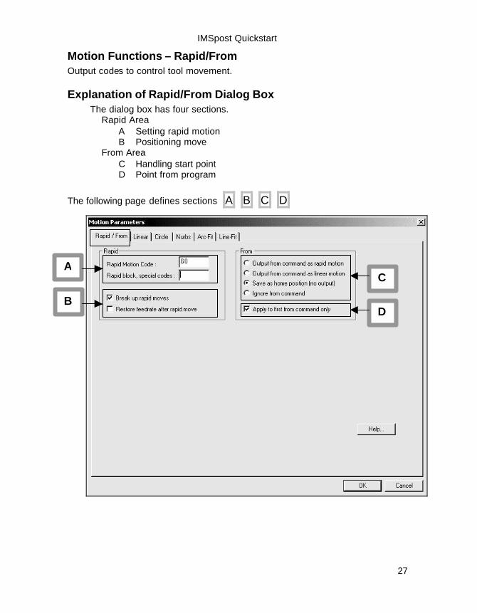
Motion Functions – Rapid/From Output codes to control tool movement.
Explanation of Rapid/From Dialog Box The dialog box has four sections. Rapid Area A Setting rapid motion B Positioning move From Area C Handling start point D Point from program
The following page defines sections A B C D
C 3
A
B D 3

IMSpost Quickstart
28
Motion Functions - Rapid Area Output codes to control tool movement.
Section A and B Rapid Area A Setting rapid motion
B Positioning move A Setting rapid motion options available:
1. Rapid motion code. G or M code, that specifies positioning motion.
2. Rapid block special codes. Function code, register, or string value using the positioning function mode.
B Positioning move options available:
3. Break up rapid moves. Output positioning moves using: a. The tool is moving away from the part, motion is made first along the tool axis, retracting from the part, and then to the final position. b. The tool moving toward the part, motion is first made to the tool axis, and then along the tool axis toward the final position
4. Restore feed after rapid move. Feedrate value output on the next
non-rapid move following a rapid motion.
1
2
3
4

IMSpost Quickstart
29
Motion Functions - From Area Output codes to control tool movement .
Section C and D From Area
C Handling starting point
D Point from program
C Handling starting point. (only one may be selected) o Output the point as a rapid positioning move. o Output the point as a linear/feed move o Save the point as a home position (no output) o Ignore from command.
D Point from program. o Apply to all from points o Apply to the first from point encountered in the program
C
D

IMSpost Quickstart
30
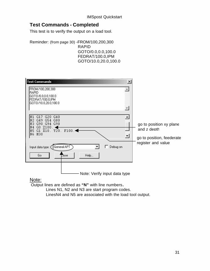
Test Commands – Load tool On-line testing. This will allow a test of parameter changes without executing the entire program. This test is to verify the output on a load tool. This page will setup the input within Text Command dialog box. The output result is displayed on the following page. Lets Do It! 1. Select Execute from pulldown. 2. Select Test Commands.
3. Displays Test Commands dialog box Identify input block, type FROM/100,200,300 RAPID GOTO/0.0,0.0,100.0 FEDRAT/100.0,IPM GOTO/10.0,20.0,100.0 4. Verify input data type – General APT is default,
otherwise change CAM system. 5. Select Go. 6. Displays dialog box, due to prompt request.
Observe number equals prior input. Select Continue , result on following page.
Input Block
Output Block
2 3
3
4
1
6
5
5
IMSpost Quickstart
31
Test Commands - Completed This test is to verify the output on a load tool. Reminder: (from page 30) -FROM/100,200,300 RAPID GOTO/0.0,0.0,100.0 FEDRAT/100.0,IPM GOTO/10.0,20.0,100.0
Note: Output lines are defined as “N” with line numbers. Lines N1, N2 and N3 are start program codes.
LinesN4 and N5 are associated with the load tool output.
go to position xy plane and z depth
go to position, feederate register and value
Note: Verify input data type

IMSpost Quickstart
32
Important Quickstart change to checklist The preceding pages will identify motion function parameters. The ability to isolate specific output results will better recognize the use of these parameters. Remove Start of Program codes from the Program Codes category. This will isolate output from the Test Commands relating to specific motion parameters.
Select from checklist
Identify text to remove
Remove text

IMSpost Quickstart
33
Motion Functions - Linear Output codes to control tool movement.
Explanation of Linear Dialog Box Incorporates slow down span conditions for the linear motion. Quickstart Note:
The use of Linear by example is beyond the intention of Quickstart and satisfies a more advanced requirement.
IMSpost Quickstart
34
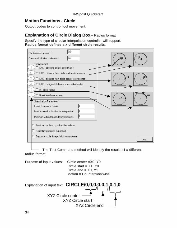
Motion Functions - Circle Output codes to control tool movement.
Explanation of Circle Dialog Box – Radius format Specify the type of circular interpolation controller will support. Radius format defines six different circle results.
The Test Command method will identify the results of a different radius format. Purpose of input values: Circle center =X0, Y0 Circle start = X1, Y0 Circle end = X0, Y1 Motion = Counterclockwise
1
2
3
4
5
6
Explanation of input text: CIRCLE/0,0,0,0,0,1,0,1,0
XYZ Circle center XYZ Circle start XYZ Circle end

IMSpost Quickstart
35
Motion Functions - Circle - Test Commands This page will setup the input within Text Commands dialog box. The output result will be the result of radius format displayed on the following page. Lets Do It! 1. Select Execute from pulldown. 2. Select Test Commands.
3. Displays dialog box, remove all text from Input Block 4. Identify input block, type GOTO/1,0,0 CIRCLE/0,0,0,0,0,1,0,1,0 5. Verify input data type – General APT is default,
otherwise change CAM system. 6. Select Close, input will be used on following pages.
Input Block
2 3
3
6
5
4
1

IMSpost Quickstart
36
Radius Format – Absolute center coordinates 1st Phase qualify radius format Lets Do It!
1. Double click Motion Functions from IMS Checklist. 2. Select Circle Tab from Motion Parameters dialog box.
4. Select I,J,K: absolute center coordinates. 5. Select OK, radius format defined.
2nd Phase output result with Test Commands Lets Do It!
1. Select Execute from pulldown. 2. Select Test Commands, displays previous input.
3. Select Go, see results
Make Selection
previous input
linear motion and circle start counterclockwise, circle end and circle center

IMSpost Quickstart
37
Radius Format – Distance from start to center 1st Phase qualify radius format Lets Do It!
1. Double click Motion Functions from IMS Checklist. 2. Select Circle Tab from Motion Parameters dialog box.
3. Select I,J,K: distance from circle start to circle center. 4. Select OK, radius format defined.
2nd Phase output result with Test Commands Lets Do It!
1. Select Execute from pulldown. 2. Select Test Commands, displays previous input.
3. Select Go, see results
Make Selection
previous input
counterclockwise, circle end and circle center linear motion and circle start

IMSpost Quickstart
38
Radius Format – Distance from center to start 1st Phase qualify radius format Lets Do It!
1. Double click Motion Functions from IMS Checklist. 2. Select Circle Tab from Motion Parameters dialog box.
3. Select I,J,K: distance from circle center to circle start. 4. Select OK, radius format defined.
2nd Phase output result with Test Commands Lets Do It!
1. Select Execute from pulldown. 2. Select Test Commands, displays previous input.
3. Select Go, see results
Make Selection
previous input
linear motion and circle start counterclockwise, circle start and circle center

IMSpost Quickstart
39
Radius Format – Unsigned distance from center to start 1st Phase qualify radius format Lets Do It!
1. Double click Motion Functions from IMS Checklist. 2. Select Circle Tab from Motion Parameters dialog box.
3. Select I,J,K: unsigned distance from center to start. 4. Select OK, radius format defined.
2nd Phase output result with Test Commands Lets Do It!
1. Select Execute from pulldown. 2. Select Test Commands, displays previous input.
3. Select Go, see results
Make Selection
previous input
counterclockwise, circle end and circle center linear motion and circle start

IMSpost Quickstart
40
Radius Format – Circle radius 1st Phase qualify radius format Lets Do It!
1. Double click Motion Functions from IMS Checklist. 2. Select Circle Tab from Motion Parameters dialog box.
5. Select R : circle radius. 6. Select OK, radius format defined.
2nd Phase output result with Test Commands Lets Do It!
1. Select Execute from pulldown. 2. Select Test Commands, displays previous input.
3. Select Go, see results
Make Selection
previous input
counterclockwise, circle end, radial value linear motion and circle start

IMSpost Quickstart
41
Radius Format – Linear moves 1st Phase qualify radius format Lets Do It!
1. Double click Motion Functions from IMS Checklist. 2. Select Circle Tab from Motion Parameters dialog box.
7. Select Break into linear moves. 8. Select OK, radius format defined.
2nd Phase output result with Test Commands Lets Do It!
1. Select Execute from pulldown. 2. Select Test Commands, displays previous input.
3. Select Go, see results
Make Selection
previous input
N2 to N79 X-Y positions, circle end
IMSpost Quickstart
42
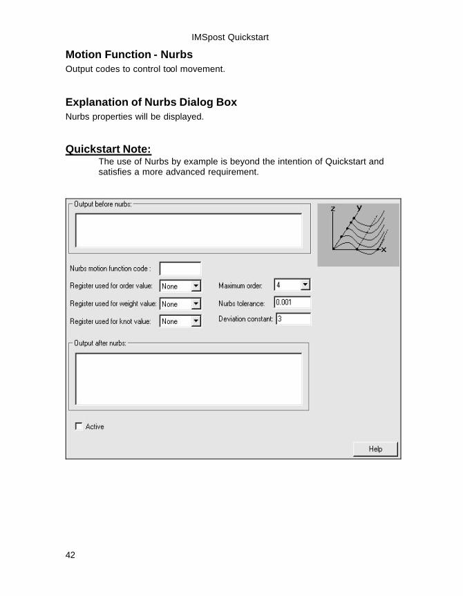
Motion Function - Nurbs Output codes to control tool movement.
Explanation of Nurbs Dialog Box Nurbs properties will be displayed. Quickstart Note:
The use of Nurbs by example is beyond the intention of Quickstart and satisfies a more advanced requirement.

IMSpost Quickstart
43
Motion Functions – Arc-Fit Output codes to control tool movement.
Explanation of Arc-Fit Dialog Box Fit an arc from a series of points
1
3
5
7
8
9
2
4
6
An interpolation of incoming points using a tolerance value defining points used for the arc fit result.
1. Minimum fit an arc points. Four point minimum. 2. Minimum required arc angle. 3. Minimum required arc radius. 4. Maximum required arc radius. 5. Tolerance value for plane fluctuation. 6. Tolerance value for radius fluctuation. 7. Plane selection, single major plane, all three planes. 8. Exact start point, exact end point to fit an arc. 9. On/Off will active/deactivate optimization results for postprocessor.
IMSpost Quickstart
44
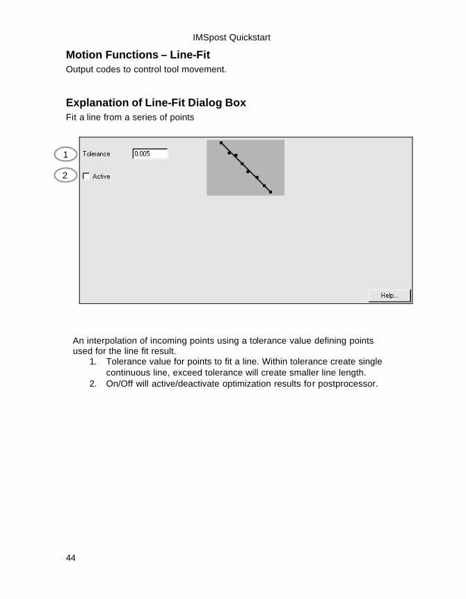
Motion Functions – Line-Fit Output codes to control tool movement.
Explanation of Line-Fit Dialog Box Fit a line from a series of points
1
2
An interpolation of incoming points using a tolerance value defining points used for the line fit result.
1. Tolerance value for points to fit a line. Within tolerance create single continuous line, exceed tolerance will create smaller line length.
2. On/Off will active/deactivate optimization results for postprocessor.
IMSpost Quickstart
45
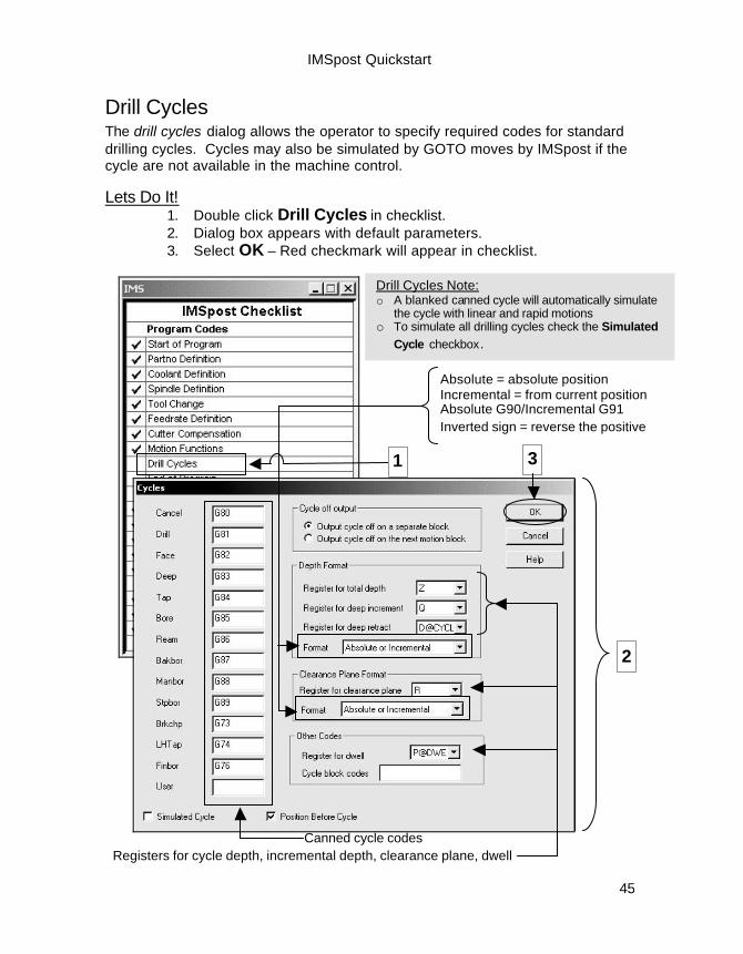
Drill Cycles The drill cycles dialog allows the operator to specify required codes for standard drilling cycles. Cycles may also be simulated by GOTO moves by IMSpost if the cycle are not available in the machine control.
Lets Do It! 1. Double click Drill Cycles in checklist. 2. Dialog box appears with default parameters. 3. Select OK – Red checkmark will appear in checklist.
Drill Cycles Note: o A blanked canned cycle will automatically simulate
the cycle with linear and rapid motions o To simulate all drilling cycles check the Simulated
Cycle checkbox.
Canned cycle codes Registers for cycle depth, incremental depth, clearance plane, dwell
Absolute = absolute position Incremental = from current position Absolute G90/Incremental G91 Inverted sign = reverse the positive
3
2 3
1

IMSpost Quickstart
46
End of Programs The end of program dialog controls what codes are output at the end of every program. These codes typically set up the final state of the machine – turning off coolant, moving the machine to a home position, and the like. Lets Do It!
1. Double click End of Program in checklist. 2. Enter text as shown in dialog box, no spaces required.
Multiple lines are allowed. 3. Select OK – Red checkmark will appear in checklist.
Default
1
2
3

IMSpost Quickstart
47
Program Codes - Save project file Customizing the post processor is achieved by editing the Program Codes in the IMSpost Checklist. Currently you have an unsaved project filed named milling_def.prj. Now is the time to Save As MyQuickstart.prj
IMSpost Checklist status The checklist define three categories
• Program Codes – modified parameters • Controller Format - unchanged parameters • Machine Format - unchanged parameters
Checkmarks indicates default or assigned parameter values.
IMSpostChecklist status.
Completed

IMSpost Quickstart
48
Continue Customizing the post processor The program codes have been defined and the project file named MyQuickstart.prj is saved.
Controller Format Reminder: The checkmarks in the IMSpost Checklist are displayed by default. The checkmarks indicate predefined parameters for the selected machine. Double click checkmark to remove checkmark; a parameter change will redisplay the checkmark, a visual verification.
Lets Do It! Remove checkmarks from Controller Format Category (not all). Sequence Numbers Comment Blocks Register Format Sort Output
Checkmarks removed After
Default IMSpost Checklist Before

IMSpost Quickstart
49
Sequence Numbers The sequence number dialog controls the output of block numbers for the posted program – what code is to be used, the start and increment values for the numbering, whether to use block numbers at all, etc. Lets Do It!
1. Double click Sequence Numbers in checklist. 2. Dialog box appears with default parameters. 3. Edit Start value to 5. 4. Edit Increment value to 10 5. Edit Maximum value to 40 6. Select OK – Red checkmark will appear in checklist
Block Number Note: The program code will start with line N5 Each line will increment by 10; N15, N25… Maximum line number is 40
1
2
5 4
3 6
Default parameters

IMSpost Quickstart
50
Comment Blocks The comment blocks dialog specifies what characters are interpreted by the control as the start of a comment, and various comment formatting options. Comments may also be excluded from the final output using this dialog. Lets Do It!
1. Double click Comment Blocks in checklist. 2. Dialog box appears with default parameters. 3. Edit Prefix string to <!>. 4. Edit Suffix string to !+! 5. Select OK – Red checkmark will appear in checklist
1
2
Default parameters
4
3 5
Partial result from NC file % Quickstart A100. N1 G17 G20 G40 N2 G49 G54 G80 N3 G90 G94 G98 <!>TOOLEND !+! <!>ROUGHCUTTING !+! <!>TOOL DIAMETER:25.4!+!

IMSpost Quickstart
51
Register Format The register format dialog provides numerous options for formatting the various registers, including decimal format, modality, leading & trailing zeros, and more. Lets Do It!
1. Double click Sequence Numbers in checklist. 2. Dialog box appears with multiple registers, select Basic. 3. Edit Digits to 4.5. 4. Edit Dec to ON 5. Edit Trail to ON 6. Identify K register, observe Test Output, verify register results 7. Select OK – Red checkmark will appear in checklist
Register = KDigits = 4.5
Decimal = ONTrailing zeros = ON
1
Divided into two sections –select Basic
3 5 6 4
2
6
IMSpost Quickstart
52
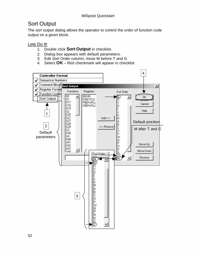
Sort Output The sort output dialog allows the operator to control the order of function code output on a given block. Lets Do It!
1. Double click Sort Output in checklist. 2. Dialog box appears with default parameters. 3. Edit Sort Order column, move M before T and G 4. Select OK – Red checkmark will appear in checklist
1
Default parameters
2 Default position
M after T and G
3
4
IMSpost Quickstart
53
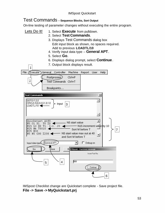
Test Commands – Sequence Blocks, Sort Output
On-line testing of parameter changes without executing the entire program.
2
N5 start value N15 increment value by 10
Input
Sort M before T
3
N5 start value max out at 40 and Sort M before T
7
4
6
5
IMSpost Checklist change are Quickstart complete - Save project file. File -> Save -> MyQuickstart.prj
Lets Do It! 1. Select Execute from pulldown. 2. Select Test Commands.
3. Displays Test Commands dialog box Edit input block as shown, no spaces required.
Add to previous LOADTL/10 4. Verify input data type – General APT. 5. Select Go. 6. Displays dialog prompt, select Continue . 7. Output block displays result.
1

IMSpost Quickstart
54
Tape Format The Tape Format dialog allows for specific formatting of the NC output file, such as start and end blocks, file size limits, and end block characters. Lets Do It!
1. Select Controller from toolbar ↓. 2. Select Tape Format from pulldown. 3. Dialog box appears with default parameters. 4. Select OK.
1
Default parameters
3
4
IMSpost Quickstart
55
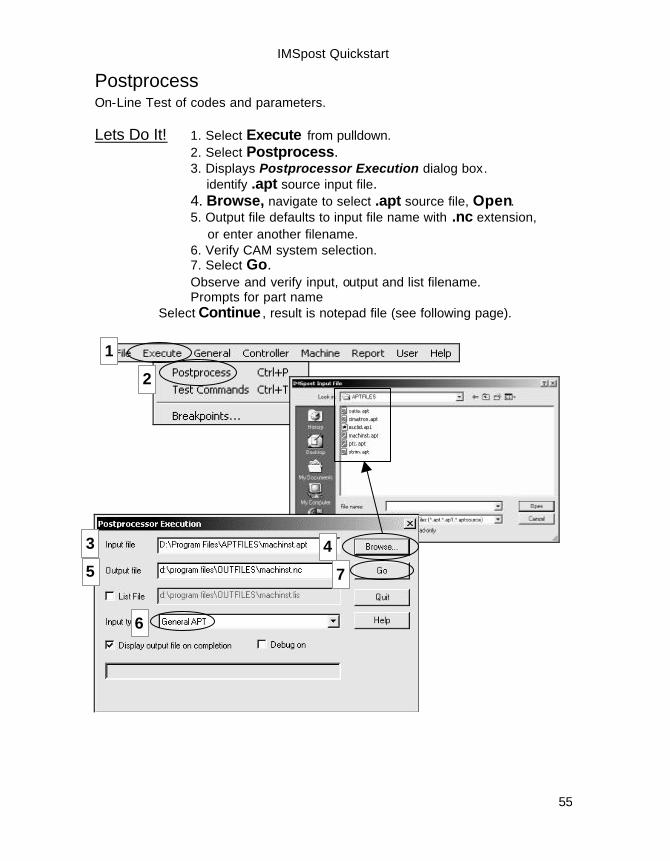
Postprocess On-Line Test of codes and parameters. Lets Do It! 1. Select Execute from pulldown. 2. Select Postprocess.
3. Displays Postprocessor Execution dialog box. identify .apt source input file. 4. Browse, navigate to select .apt source file, Open. 5. Output file defaults to input file name with .nc extension,
or enter another filename. 6. Verify CAM system selection. 7. Select Go. Observe and verify input, output and list filename. Prompts for part name
Select Continue , result is notepad file (see following page).
1
2
3 3
4
5
6
7

IMSpost Quickstart
56
Postprocessor – Text File Output The file name is the default product name with the extension .nc. This output file starts at N1 and finishs with N974 File will be stored in the /outfiles folder
Comment Block definition, page 49
Tape format definition, page 53
Tape format definition, page 53