QUICKSTART GUIDE V4 - -= BEASTX · QUICKSTART GUIDE V4.1. 1. ... SRXL (V1+V2), Jeti® UDI,...
28
StudioX allows to edit, save and load the device setup by using a PC. Additionaly it can be used to register your device and aquire optional features. Also it allows to perform very special setups like such as a virtual swashplate rotation for multiblade rotorheads. To connect your MICROBEAST PLUS to the computer the optional available USB2SYS interface is required. StudioX can be downloaded from: STUDIOX.BEASTX.COM This guide only is intended to be used with MICROBEAST PLUS firmware version 4.1.x! Firmware version: 4.1.x In the left row Menu-LED C stands for major version „4“. In right row Menu-LED H shows minor version „1“. You can see what firmware version your MICROBEAST PLUS is running when it is powered on. First the device carries out a brief LED test. Then for about 3 seconds the Status-LED lights red while the Menu-LEDs A - G display the first digit of the firmware version and the LEDs H - N the second digit of the firmware version. Dear customer, thank you for purchasing our product. MICROBEAST PLUS is a high-end flybarless system for RC helicopters that has been developed in Germany using latest technology and setting high standards. This system can be used with nearly any size and type of RC helicopters and besides using it as flybarless stabilization system it offers additional features that can make flying helis even easier and comfortable. To program MICROBEAST PLUS we consciously decided against using a tiny display that might be hard to read or using an external programming device such as a smart phone or PC software. The „EasySetup“ concept allows to setup the helicopter in a very short amount of time and without the need of additional devices which you might have forgotten at home when on the flying field. You can setup your helicopter anytime and anywhere and you‘re ready for take off within a few minutes. This Quickstart Guide is a clearly arranged guide that will lead you step-by-step through the basic flight setup. Please follow this guide carefully and make sure to read the attached safety notes. For a detailed instruction manual and a lot more details, tipps, tricks and notes about the product please visit WIKI.BEASTX.COM QUICKSTART GUIDE V4.1
Transcript of QUICKSTART GUIDE V4 - -= BEASTX · QUICKSTART GUIDE V4.1. 1. ... SRXL (V1+V2), Jeti® UDI,...

StudioX allows to edit, save and load the device setup by using a PC. Additionaly it can be used to register your device and aquire optional features. Also it allows to perform very special setups like such as a virtual swashplate rotation for multiblade rotorheads. To connect your MICROBEAST PLUS to the computer the optional available USB2SYS interface is required.StudioX can be downloaded from:STUDIOX.BEASTX.COM
This guide only is intended to be used with MICROBEAST PLUS firmware version 4.1.x!
Firmware version: 4.1.xIn the left row Menu-LED C stands for major version „4“. In right row Menu-LED H shows minor version „1“.
You can see what firmware version your MICROBEAST PLUS is running when it is powered on. First the device carries out a brief LED test. Then for about 3 seconds the Status-LED lights red while the Menu-LEDs A - G display the first digit of the firmware version and the LEDs H - N the second digit of the firmware version.
Dear customer,thank you for purchasing our product.MICROBEAST PLUS is a high-end flybarless system for RC helicopters that has been developed in Germany using latest technology and setting high standards. This system can be used with nearly any size and type of RC helicopters and besides using it as flybarless stabilization system it offers additional features that can make flying helis even easier and comfortable.To program MICROBEAST PLUS we consciously decided against using a tiny display that might be hard to read or using an external programming device such as a smart phone or PC software. The „EasySetup“ concept allows to setup the helicopter in a very short amount of time and without the need of additional devices which you might have forgotten at home when on the flying field. You can setup your helicopter anytime and anywhere and you‘re ready for take off within a few minutes.This Quickstart Guide is a clearly arranged guide that will lead you step-by-step through the basic flight setup. Please follow this guide carefully and make sure to read the attached safety notes. For a detailed instruction manual and a lot more details, tipps, tricks and notes about the product please visit WIKI.BEASTX.COM
QUICKSTART GUIDE V4.1

1. HARDWARE INSTALLATION
You can position MICROBEAST PLUS flat or upright on the helicopter. The large socket must point to the front or to the rear of the helicopter. The small white socket must be aligned with the longitudinal axis.
The sensor axis (housing edges of the device) must be aligned exactly parallel to all three rotation axis of the helicopter. However, it is allowed to position the device offset from the rotation axis.
In summary there are 8 mounting orientations possible:
1. flat, sticker on top, socket pointing to front
2. upright, button up, socket pointing to front
3. flat, sticker showing to ground, socket pointing to front
4. upright, button down, socket pointing to front
5. flat, sticker on top, socket pointing to rear
6. upright, button up, socket pointing to rear
7. flat, sticker showing to ground, socket pointing to rear
8. upright, button down, socket pointing to rear
Use one of the supplied 3M gyro pads to stick the device to your helicopter. The device housing must not directly touch the chassis of the helicopter. When connecting and laying out the servo and receiver wiring later onwards please make sure the wires do not pass tension to the MICROBEAST PLUS. It is not recommended to bundle or tie down the leads close to the MICROBEAST PLUS device.
1. 2. 3. 4.
5. 6. 7. 8.
Flight direction

2. CONNECTING THE RECEIVER
BAT
Pitch
Gyro
Rudder
Elevator
Aileron
Throttle
STANDARDRECEIVER
Throttle servo/ESC
redbrown
orange
BEC/Receiver battery(if required)
BAT
SINGLE-LINERECEIVER
Throttle servo/ESC
BEC/Receiver battery(if required)
Signal
JR® orSpektrum®
remotesatellite
Throttle servo/ESC
BEC/Receiver battery (if required)or Spektrum® bind plug
Satellite adapter(BXA76009)
Supported receivers/transmission protocols:• SRXL: JR® XBus (Mode B), Multiplex®
SRXL (V1+V2), Jeti® UDI, Graupner/SJ® HOTT SUMD, Spektrum® SRXL
• Futaba® SBUS• Spektrum® remote satellite (DSM2/
DSMX)• JR DMSS remote satellite (JR RJ01)• PPM serial signal (SPPM)
Using a single remote satellite is only recommended for 450 size helis or smaller! For larger helis you may use a SRXL compatible Single-Line receiver.
The illustrations are only intended as examples!The function assignment of the transmitter determines which channel on the receiver controls which function.
Using a Single-Line receiver all channels/functions are transferred by one single connection wire. This allows to use even more than 5 channels, i. e. for controlling the nitro RPM Governor, AttitudeControl function and/or additional servo output channels.
Always make sure the power supply is stable and dimensioned sufficiently for the intended application. If possible always connect the power source directly to MICROBEAST PLUS. Especially when using standard size servos it is recommended to use more than one power supply cable in parallel to preserve a stable voltage and to reduce power loss due to connection resistance. The additional supply cables may be connected to free receiver ports. We recommend to use MICROBEAST PLUS HD which offers a low resistant high-power input and which is well suited for larger model helicopters.
The assignment of functions to the radio channels is mentioned in the manual of your radio system. Also you may find out the function assignment by checking your transmitter‘s servo monitor. The connectors of MICROBEAST PLUS are assigned to the functions as follows:AIL|CH5 = Aileron, ELE|DI1 = Elevator, RUD (orange wire) = Rudder, PIT (red wire) = Thrust, Aux (brown wire) = Gyro gainThe wires for aileron and elevator additionally transfer the power between MICROBEAST PLUS and receiver.

3. MICROBEAST PLUS HD
Using the switch is optional. The device can also be operated without the switch.Anyhow, never connect anything else than the switch to the switch port!
Input voltage range: 3,5 – 8,4 Volts.MICROBEAST PLUS HD in first line was designed for 550 size helis and larger which use standard size servos with high current consumption. Here you can connect the power supply directly to the additonal high-power input which reduces voltage loss due to contact and wiring resistance significantly when high currents are flowing. Always use the supplied power cable as connector between battery and MICROBEAST PLUS HD. It is not recommended to directly plug in the battery at the device. Continuous plugging and unplugging can cause the overlying servo plugs getting unplugged accidentally or cause the adhesive gyro pad to get loose!Receiver and servo plugs are connected to the ports on top of the unit, similar as described for the standard (non-HD) MICROBEAST PLUS.
Switch
Receiver battery or BEC
High-power connector
When switched off MICROBEAST PLUS HD consumes a very low amount of standby current. Therefore always completely disconnect the battery from the system if you do not use the model for a extended period of time to prevent the supply battery from getting discharged and damaged in consequence.
MICROBEAST PLUS HD does not supply an internal voltage regulation! The voltage that is applied to the high power connection port will directly be passed to the servo and receiver connections. Only use electronic components (servos and receiver) that are designed for your power source.
Using the high power connection port is not a must. You can also use MICROBEAST PLUS HD in a conventional manner by powering the unit from the receiver ports in the top row. However, using the electronic power switch system is not possible then.
Switch plug(Polarity not relevant)
To initiate bind procedure on a single Spektrum® remote satellite connect the Spektrum bind plug to SYS port. When using a DSMX remote satellite push and hold the button and turn on power while still holding the button down. The LED on the satellite will flash together with Menu LED H on the MICROBEAST PLUS. When binding a DSM2 remote satellite do not touch the button but only power on the device. The LED on the satellite will flash together with Menu LED N. Initiate the bind procedure on the transmitter. Power off and remove the bind plug when finished successfully.To bind the JR® RJ01 remote satellite initiate the bind procedure on the transmitter and power on the MICROBEAST PLUS. The remote satellite will bind instantly. Connecting a bind plug or similar is not necessary.

4. PREPARING YOUR TRANSMITTER
With electric driven models remove the motor from the main gear when performing the basic setup for safety reason! Additionaly deactivate the throttle by using the „Throttle HOLD“ switch, so the motor won‘t start to turn when moving the thrust stick.When flying a nitro or gasser heli remove the servo horn from the throttle servo before first power up to prevent jamming of the servo due to wrong servo setup.
You must not use any mixing functions on the output channels! Especially it is not allowed to use mixing functions for the swashplate servos. Deactivate all output channels that are not used. In the basic configuration we only need pitch, aileron, elevator, rudder, throttle and one channel to adjust the tail gyro gain.
Create a new helicopter model memory in your transmitter that supplies different flight modes for controling throttle, pitch and the tail gyro gain in different flight situations.
Only the pitch channel must be controled when moving the thrust stick.The same applies to aileron, elevator and rudder.
Each control function must exactly control one output channel. The servo throws must be set to 100% and all trims and sub trims must be zero. For the basic setup do not change the pitch curves yet. The throttle curves and throttle servo settings can be adjusted as necessary for this model in case you do not intend to use the internal RPM Governor function of MICROBEAST PLUS. If you want to use the integrated RPM Governor function also do not touch the throttle settings yet.
5. RECEIVER SETUP
Switch on power supply Menu LED A flashes
Release buttonPress and hold button Briefly push buttonPress and hold button
Skip to Menu LED Bor
End of menu (all LEDs flash)when choosing „Standard“
Status LED changes color/state(= changing receiver type)
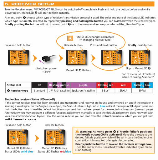
At menu point A choose which type of receiver/transmission protocol is used. The color and state of the Status LED indicates which type is currently selected. By repeatedly pressing and holding the button you can switch between the receiver types. Briefly pushing the button will skip to menu point B or to the menu end in case you selected the „Standard“ type.
Status LED off flashing purple purple flashing red red flashing blue
A Receiver type Standard JR® RJ01 satellite Spektrum® satellite S-Bus® SRXL® SPPM
Menu LED B flashesStatus LED is solid blue
Single-Line receiver (Status LED not off) If the correct receiver type has been selected and transmitter and receiver are bound and switched on and if the receiver is sending a valid signal on the Single-Line output, the Status LED must light up in blue color at menu point B. Again press and hold the button here to load the default function assignment that has been preset for the selected radio system (see next page). Alternatively you may program a different function assignment manually in case the default assignment does not work with your transmitter‘s function layout. How this works in detail you can read from the instruction manual which you can get from wiki.beastx.com.
Press and hold button Release button
Menu LED N flashesStatus LED flashes red/blue
Warning! At menu point N (Throttle failsafe position) the throttle output CH5 is activated! Move the throttle to the desired failsafe position which will be set in case the Single-Line connection is interupted oder gets disconnected.Briefly push the button to save all the receiver settings now. Then the end of menu is reached which is indicated by all menu LEDs flashing.
To enter Receiver menu MICROBEAST PLUS must be switched off completely. Push and hold the button before and while powering on. Menu LED A will start to flash instantly.
JR® RJ01satellite
Spektrum®satellite Futaba® S-BUS PPM serial signal (SPPM)
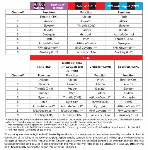
Channel* Function Function Function1 Throttle (CH5) Aileron Pitch2 Aileron Elevator Aileron3 Elevator Throttle (CH5) Elevator4 Rudder Rudder Rudder5 Gyro gain Gyro gain AttitudeControl6 Pitch Pitch Throttle (CH5)7 AttitudeControl AttitudeControl Gyro gain8 RPM Governor*** RPM Governor*** RPM Governor***9 Auxiliary (CH6) Auxiliary (CH6) Auxiliary (CH6)
SRXL
BEASTRX®Multiplex® SRXL
JR® XBUS Mode BJETI® UDI
Graupner® SUMD Spektrum® SRXL
Channel* Function Function Function Function1 Aileron Aileron Pitch Throttle (CH5)2 Elevator Elevator Aileron Aileron3 Throttle (CH5) Rudder Elevator Elevator4 Rudder Pitch Rudder Rudder5 Gyro gain Throttle (CH5) AttitudeControl** Gyro gain6 Pitch Gyro gain Throttle (CH5) Pitch7 AttitudeControl** AttitudeControl** Gyro gain AttitudeControl**8 RPM Governor*** RPM Governor*** RPM Governor*** RPM Governor***9 Auxiliary (CH6) Auxiliary (CH6) Auxiliary (CH6) Auxiliary (CH6)
When using SRXL the preset channel assignment is based on the receiver‘s protocol version. MICROBEAST PLUS will detect automati-cally which brand of receiver is used and will choose the appropriate channel assignment accordingly.* Channel designation of Spektrum® transmitters: THR, AIL, ELE, RUD, GER, PIT, AX2, AX3, AX4** only applicable with ProEdition firmware otherwise this channel by default controls CH6 Auxiliary output instead of channel 9*** only for models with nitro or gas engine
When using a receiver with „Standard“ 5-wire layout the function assignment is simply determined by the order of physical connection of the wires to the receiver outputs. Assignment by software is not provided and will not appear when choosing this type of receiver. Here the AttitudeControl function (optional) will be controlled using the tail gyro gain channel. The RPM Governor function can‘t be used in combination with this type of receiver. After choosing „Standard“ (Status LED off) at menu point A and briefly pushing the button receiver setup is finished.
Move rudder stickleft or right
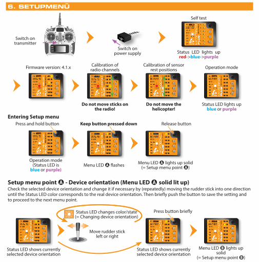
6. SETUPMENÜ
Switch onpower supply Status LED lights up
red->blue->purple
Status LED lights upblue or purple
Self test
Operation mode
Switch ontransmitter
Entering Setup menu
Setup menu point A - Device orientation (Menu LED A solid lit up)Check the selected device orientation and change it if necessary by (repeatedly) moving the rudder stick into one direction until the Status LED color corresponds to the real device orientation. Then briefly push the button to save the setting and to proceed to the next menu point.
Operation mode(Status LED is
blue or purple)
Press and hold button
Menu LED A flashes
Keep button pressed down
Menu LED A lights up solid(= Setup menu point A)
Release button
Status LED shows currently selected device orientation
Status LED shows currently selected device orientation
Menu LED B lights up solid
(= Setup menu point B)
Press button brieflyStatus LED changes color/state(= Changing device orientation)
Calibration of radio channels
Do not move sticks on the radio!
Calibration of sensor rest positions
Do not move the helicopter!
Firmware version: 4.1.x

Status LED off* Status LEDflashing purple Status LED purple Status LED
flashing red
Large socket points to nose of the heli
Status LED red Status LEDflashing blue Status LED blue Status LED flashing
red/blue
Large socket points to tail of the heli
Setup menu points B, C and DThe currently selected swashplate servo update rate (B), rudder servo update rate (D) and rudder servo center pulse (C) are indicated by the color and state of the Status LED at each menu point. By moving the rudder stick to one or another direction you can change between the available options (if necessary). Briefly pressing the button will save the selected option and move to the next menu point.
Status LED shows current swashplate servo frame rate
Setup menupoint C
Press button briefly
Status LED shows current swashplate servo frame rate
Status LED off purple flashing red red flashing blue blue
B Swashplate servoupdate rate User defined 50 Hz* 65 Hz 120 Hz 120 Hz 200 Hz
C Rudder servo center pulse User defined 960 µs - 760 µs - 1520 µs*
D Rudder servo update rate User defined 50 Hz* 120 Hz 270 Hz 333 Hz 560 Hz
If you don‘t know what the maximum update rate that is tolerated by your servos never use more than 50Hz.The higher the update rate the better it is for the flight performance of MICROBEAST PLUS but you must check the servo specifications before increasing the update rate. Otherwise the servos may get damaged! See WIKI.BEASTX.COM for a list with parameter examples for most servo types commonly used in flybarless helicopters.
...Move rudder stickleft or right
Status LED changes color/state (Changing swash servo frame rate)
Flight direction

Menu LED E solidStatus LED off
Use rudder stick to move the servo to the maximum allowed deflection Release rudder stick Status LED
blue or red
Use rudder stick to move the servo to the minimum allowed deflection Release rudder stick Status LED
purple
Press button briefly
Menu LED F solid(= Menu point F)
Setup menu point E - Rudder servo limitPlug the rudder servo connector into CH4 output of MICROBEAST PLUS. Put the servo arm on the servo so that it forms roughly an angle of 90 degrees with the rudder linkage rod and adjust the length of the linkage rod as described in the helicopter manual.
When moving the rudder stick check if the servo is moved into the correct direction so that the helicopter will be moved correctly in flight. If this is not the case use the servo reverse function of your transmitter and reverse the channel output that controls the rudder function.
Push and hold the rudder stick into one direction to move the rudder servo and release the stick when the servo reaches the maximum or mimimum allowed servo throw. Using the rudder stick you can reposition the servo at any time to adjust the exact servo limit. If you do not touch the rudder stick for several seconds the current servo position will be saved as maximum or minimum (the Status LED will flash and then light up solid in blue or red color). Then move the servo to the opposite direction and wait until also this position gets stored (Status LED becomes purple).

Setup menu point F - Tail gyro directionLift the helicopter at the rotorhead and turn it on the vertical axis by hand. Observe in which direction the rudder servo moves the tail rotor when turning the heli. The tail rotor must produce thrust against the direction of movement so that the rotation will be stopped by the gyro in flight. For example if you move the helicopter‘s nose to the left the gyro must steer to the right similar as you would move the rudder stick to the right manually.
Wrong Correct
Turning heli to the left
Turning heli to the left
Gyro steers left
Gyro steers
to the right
Note: These pictures are only exemplary. Check your helicopter‘s manual to find out which direction your tail rotor has to move.
If necessary reverse the tail gyro direction by briefly pushing the rudder stick into one direction at menu point F (Status LED color will change).Then briefly push the button to proceed with setting up menu point G.
Setup menu point G - Swashplate servo trimPlug all three swashplate servos to the outputs marked with CH1 to CH3 in the order as shown below. Then put the servo arms on the servos so that they form roughly an angle of 90 degrees with the linkage rods.
CH1
CH
120°
CH1
CH2 CH3
140°
CH1
CH2 CH3
Flig
ht d
irec
tion 90°
CH1
CH H32 C2 CH3CH
mechanicalswash mixing
eCCPM
Servo 1Elevator
Servo 2Aileron
Servo 3Pitch/Aileron
top

By moving the rudder stick into one direction repeatedly select one servo after another and adjust each servo‘s center position by moving the elevator stick forwards or backwards so that the servo arm is positioned exactly 90 degrees to the linkage rod. The servo number that is currently selected and that can be trimmed at the moment is indicated by the Status LED color.
When the servos are adjusted perfectly let one servo selected (only the electrical trim positions are important and are used in the further steps) and adjust the linkage rods going from servos to the swashplate and from the swashplate to the blade grips. The swashplate must be leveled and centered on the main shaft and the bladegrips should be set to 0° pitch. Then briefly push the button to get to menu point H.
Anti-rotation guide leveled horizontally and twisted correctly
Swashplate leveled horizontally
0° pitch
Swashplate centered vertically on main shaft
Status LED off(= no servo active)
Choose one of the servos connected at CH1 - CH3
Move rudder stick left or right
Status LED color indicates selected servo number
Move elevator stick to adjust servo center position
Check all servo positions by selecting each servo once even when the servo arms are perfectly positioned when Status LED is off.
If necessary adjust the swashplate anti-rotation guide so that there is no swashplate phasing (only applies to 2-blade rotorheads).
Linkage balls of swashplate outer ring and blade grips must be on one line

Setup menu point I - Swashplate servo directionsOnly move the thrust stick and check if all servos push the swashplate up and down simultaneously. If this is not the case move the rudder stick into one direction once to switch to the next servo configuration and try again. Repeat this until the servos move the swashplate correctly. There are four possible configurations and only one will be correct.
Press button brieflyStatus LED changes color/state(= changing mixing type)
Move rudder stickleft or right
Status LED shows currently selected mixing type
Status LED off purple flashing red red flashing blue blue
H Swashplate mixing type User defined mechanical 90° 120° 140° 135°/140° (1:1)
Setup menu point H - Swashplate mixing type
Status LED shows currently selected mixing type
Status LED shows currently selected servo configuration
Move thrust stickup and down
Status LED changes color/state(= changing servo combination)
Move rudder stickleft or right
Now also check if the sticks are moving the swashplate in the correct directions. If one or more directions are wrong use the servo reverse function of your transmitter to reverse the channel output for the channel which controls the specific function. Do not use the servo reverse function of MICROBEAST PLUS to change stick directions!
When the swashplate can be controlled by the sticks correctly, briefly push the button to skip to menu point J.
Status LED shows currently selected servo configuration

Setup menu point J - Swashplate servo throwAlign rotorhead and rotorblades in parallel to the helicopter‘s longitudinal axis. Attach a pitch gauge/level meter to one of the rotor blades or to a blade grip in order to measure aileron pitch.
Push and hold aileron stick into one direction of your choice just until
exact +6 oder -6 degrees of pitch are reached
Menu LED J solidStatus LED off
Status LED should be solid blue(See instruction manual for
further details on the LED colors)
Menu LED K solid(= Menu point K)
Press button briefly
Setup menu point K - Collective pitch
Move thrust stick to maximum positive pitch
and let it stay there
Move thrust stick to full negative pitch and let it
stay there
Move aileron stick to adjust maximum negative collective pitch (i. e. -12°)
Move aileron stick to adjust maximum positive collective pitch (i. e. +12°)
Status LED must be blue when collective pitch is
positive!
Status LED red Move rudder stickleft or right
Status LED red when collective pitch is
negative!
Press button briefly
Status LEDgets blue
6°0°
+12°
-12°

Setup menu point M - Swashplate gyro directionsLift the helicopter at the rotor head and tilt it by hand forwards and sideways. Watch how the gyro is correcting the swashplate. The system has to steer against the movement of the helicopter keeping the swashplate level. If the swashplate tilts into the direction of movement you have to reverse the compensation direction for this axis.
Menu LED L solidStatus LED shows the
amount of limiting
Move thrust, aileron and elevator sticks carefully to
maximum deflection!
Press button briefly
Move rudder stick to adjust the servo limit
Status LED should be solid blue(See instruction manual for
further details on the LED colors)
Setup menu point L - Swashplate servo limitYou can remove the pitch gauge now! Simultaneously move the sticks for thrust, aileron and elevator to the maximum deflection and check if the servos, swashplate or linkages get jammed in a certain position. By pushing and holding the rudder stick left or right you can increase or decrease the limit for the servos! Adjust the limit so that the servos just don‘t get jammed in any possible stick position but don‘t limit the servos more than necessary.
Status LED shows current swashplate gyro directions
Press button brieflyStatus LED changes color(= changing gyro direction)
Move rudder stickleft or right
Status LED shows current swashplate gyro directions

When you‘re using the RPM Governor of MICROBEAST PLUS now connect the RPM sensor (i. e. magnetical, optical or brushless phase sensor) or the wire for RPM signal of your ESC to the white sensorport on the long side. For this you may need the optional available BXA76401 adapter.
Setup menu point N - Internal RPM GovernorThis menu point is only accessible if you‘re not using a Standard type receiver! Otherwise pressing the button at menu point M will exit the menu and lead back to operation mode.
Enable the internal RPM Governor function by choosing the type of drive system of your helicopter. If you‘re using the governor function of the ESC or an external governor or if you want to fly without headspeed governing at all, select „Governor off“.
Status LED shows current RPM Governor mode
Press button brieflyStatus LED changes color(= changing RPM Governor mode)
Move rudder stickleft or right Status LED shows current RPM
Governor mode
Status LED off red blue
N Internal RPM Governor Governor off* electric heli nitro/gas heli
ESC
Speed controller connected to CH5
Throttle servo connected to CH5
Magnetical sensor mounted close to
clutch bell of motor

7. GOVERNOR SETUP MENU
Menü LED A flashesStatus LED off
Menü LED A flashesStatus LED off
Press button briefly
Stop
Nitro/Gas heli
Electric heli with brushless phase sensor
Menu LED A flashesStatus LED off
Carefully add throttle until motor starts to turn Status LED is solid red as long as motor turns
Motor off position
Turn clutch bell by hand Status LED solid bluewhen magnet triggers sensor
Press button briefly
Status LED off when no magnet under sensor or when
second magnet is passed(this may vary)
Governor menu point A - Test mode (Menu LED A flashing slowly) If the RPM Governor was activated at Setup menu point N (setting „electric“ or „nitro/gas“ heli) you can access the Governor menu immediately afterwards. At menu point A we check if the rpm sensor is functioning properly and if the rpm sensor wire is connected correctly.
Thrust in mid stick position
Servo arm and throttle lever in parallel and
perpendicular to linkage rod
Additionaly when using a helicopter with combustion engine you may adjust the throttle servo positions in the transmitter (servo throw and servo center) and setup the throttle on the heli (throttle linkage rod length and servo arm position) if necessary. Attach the servo horn at thrust mid stick position. The throttle linkage must form a right angle with the servo horn. Adjust the length of the linkage according to the instructions of the helicopter so that it also is positioned perpendicular to the linkage lever at the carburetor. The carburetor must be opened halfways (note the markings on the carburetor!). Then adjust the servo throw so the carburetor can be fully opened and fully closed without jamming the throttle servo.

Governor menu point B - Motor off/Idle positionUsing an electric heli move the throttle to the position at which the motor is just before to start running, i.e. by adding throttle until the motor starts to turn and then reducing the throttle a little. With a nitro/gas heli move the throttle to a stable idle position.
Menu LED B flashesStatus LED off
Move throttle to position at which the motor is just before to start running (electric heli) or idle position (nitro/gas heli)
Press button briefly
Status LED blue when throttle
position registered
Governor menu point C - Full throttle positionMove throttle to maximum position. Note: In electric governor mode the throttle input will not be passed to CH5 output to prevent from motor damage by running the motor without load! Thus, you have to check before that the full throttle position runs the motor at maximum speed in reality, i.e. by correctly programming your throttle end points in the transmitter or ESC.
Menu LED C flashesStatus LED off Move throttle to maximum position
MAX RPM
Governor menu point D - Transmitter setupHere we can set the desired rotor headspeed and throttle curves. The Status LED can be used to verify the transmitter setup. When using an electric heli the throttle is completely independent from the thrust stick. The throttle curves are set to horizontal lines which stand for a certain headspeed and governor operation mode. Using the flight mode switch you can switch between the different curves in the transmitter.
The RPM Governor for nitro/gas models can be operated in two different ways. One possibility is to operate the governor using the throttle channel just like in electric mode. Only difference is that the the range below 50% throttle can be used to manually control the throttle servo, i.e. for starting the motor. When the motor is running you can switch in the area above 50% which is used to enable the governor and preset a specific rotor headspeed.
Motor off• Throttle 0% over
the entire range
Idle up• Throttle set between
15% and 100% equals headspeed of 600 - 4000rpm
• +5% = +200rpm
100%
0%
Autorotation• Motor off• When switching back
to idle up motor will restart quickly
10%
Status LED blueStatus LED off Status LED redor purple
50% 2000rpm
Status LED blue when throttle
position registered
Press button briefly

The second option to control the RPM Governor for nitro/gas helicopters is to use a separate switch channel. Here you can use the throttle curves to manually control the throttle servo completely. The RPM Governor is activated and the headspeed is preset by using the additional channel. When the throttle channel is above 25% and a headspeed is preset, the RPM Governor will control this headspeed. Moving the throttle below 25% will set Autorotation mode while the RPM Governor is still activated in the background.
Manual control• Range between
0% und 50% directly controls the throttle servo
Autorotation• Throttle in idle
position• When switching back
to idle up (>50%) motor will restart quickly
• Switching back to manual control (<40%) will disable governor
45%
Status LED blueStatus LED off
Idle up• Throttle set between
50% and 100% equals headspeed of 600 - 3000rpm
• +5% = +240rpm
Status LED redor purple
75% 1800rpm
100%
0%
50%
Manual control• Throttle curve
controls servo• Governor off• Governor channel
below 5% (-90)
Status LED off
50%
100%
0%
100%
0%
Throttle curve(throttle channel)
Governor control channel
Governor menu point E - Signal dividerElectric helicopter with brushless phase sensor or phase signal from ESC: signal divider = motor pole count : 2Nitro/Gas helicopter with magnetical or optical sensor: signal divider = number of triggers (i.e. magnets or optical markers)
Governor menu points F G H - Main gear ratioWhen the helicopter has a single stage main gear: Main gear ratio = Main gear tooth count : Motor pinion tooth countSet the Status LED color/state at each of the menu points F, G and H so that the main gear ratio can be calculated as sum of the three menu points, i. e. 8.55:1 = F flashing purple + G purple + H flashing red
Idle up• Governor channel set
between 5% and 100% (or -90 and +100 on some transmitters) equals headspeed of 600 - 3000rpm
• +5% (or 10 clicks) = +126rpm• throttle channel must stay
above 25%Status LED red or purple
Throttle curve(throttle channel)
Governor control channel
50%
100%
0%
100%
0%
52,5%1800rpm
Status LED off flashing purple purple flashing red red flashing blue blue
E Signal divider 1 2 3 4* 5 6 7
Status LED off flashing purple purple flashing red red flashing blue blue red/blue
FUser
definded 8.00 9.00* 10.00 11.00 12.00 13.00 14.00
G +0.00 +0.20 +0.40* +0.60 +0.80 - - -
H +0.00 +0.05 +0.10* +0.15 - - - -
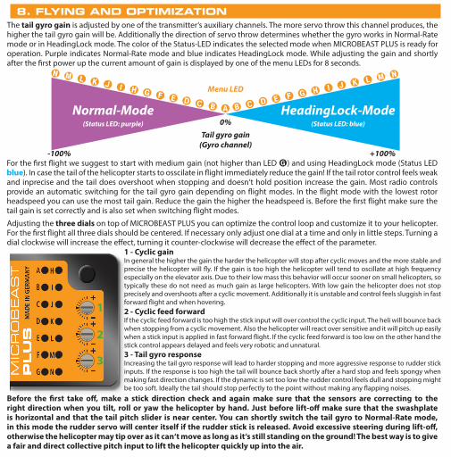
8. FLYING AND OPTIMIZATION
Before the first take off, make a stick direction check and again make sure that the sensors are correcting to the right direction when you tilt, roll or yaw the helicopter by hand. Just before lift-off make sure that the swashplate is horizontal and that the tail pitch slider is near center. You can shortly switch the tail gyro to Normal-Rate mode, in this mode the rudder servo will center itself if the rudder stick is released. Avoid excessive steering during lift-off, otherwise the helicopter may tip over as it can‘t move as long as it‘s still standing on the ground! The best way is to give a fair and direct collective pitch input to lift the helicopter quickly up into the air.
The tail gyro gain is adjusted by one of the transmitter‘s auxiliary channels. The more servo throw this channel produces, the higher the tail gyro gain will be. Additionally the direction of servo throw determines whether the gyro works in Normal-Rate mode or in HeadingLock mode. The color of the Status-LED indicates the selected mode when MICROBEAST PLUS is ready for operation. Purple indicates Normal-Rate mode and blue indicates HeadingLock mode. While adjusting the gain and shortly after the first power up the current amount of gain is displayed by one of the menu LEDs for 8 seconds.
For the first flight we suggest to start with medium gain (not higher than LED G) and using HeadingLock mode (Status LED blue). In case the tail of the helicopter starts to osscilate in flight immediately reduce the gain! If the tail rotor control feels weak and inprecise and the tail does overshoot when stopping and doesn‘t hold position increase the gain. Most radio controls provide an automatic switching for the tail gyro gain depending on flight modes. In the flight mode with the lowest rotor headspeed you can use the most tail gain. Reduce the gain the higher the headspeed is. Before the first flight make sure the tail gain is set correctly and is also set when switching flight modes.
B C D E F G H I J K L M N N M L K J I H G F E D C B
-100% +100%
0%
A
Menu LED
Tail gyro gain(Gyro channel)
Normal-Mode(Status LED: purple)
HeadingLock-Mode (Status LED: blue)
Adjusting the three dials on top of MICROBEAST PLUS you can optimize the control loop and customize it to your helicopter. For the first flight all three dials should be centered. If necessary only adjust one dial at a time and only in little steps. Turning a dial clockwise will increase the effect, turning it counter-clockwise will decrease the effect of the parameter.
3 - Tail gyro responseIncreasing the tail gyro response will lead to harder stopping and more aggressive response to rudder stick inputs. If the response is too high the tail will bounce back shortly after a hard stop and feels spongy when making fast direction changes. If the dynamic is set too low the rudder control feels dull and stopping might be too soft. Ideally the tail should stop perfectly to the point without making any flapping noises.
1 - Cyclic gainIn general the higher the gain the harder the helicopter will stop after cyclic moves and the more stable and precise the helicopter will fly. If the gain is too high the helicopter will tend to oscillate at high frequency especially on the elevator axis. Due to their low mass this behavior will occur sooner on small helicopters, so typically these do not need as much gain as large helicopters. With low gain the helicopter does not stop precisely and overshoots after a cyclic movement. Additionally it is unstable and control feels sluggish in fast forward flight and when hovering.2 - Cyclic feed forwardIf the cyclic feed forward is too high the stick input will over control the cyclic input. The heli will bounce back when stopping from a cyclic movement. Also the helicopter will react over sensitive and it will pitch up easily when a stick input is applied in fast forward flight. If the cyclic feed forward is too low on the other hand the stick control appears delayed and feels very robotic and unnatural.
1
2
3

9. PARAMETER MENU
Entering Parameter menu
Menu point A - Swashplate quick trim (Menu LED A flashing)Move the stick(s) for aileron and elevator to trim the swashplate into the desired direction. When using the tail gyro in Normal-Rate mode you can store the last servo position by pressing and holding the button for 2 seconds. To delete all trimmings that have recently been made briefly push the rudder stick.
Operation mode(Status LED is
blue or purple)
Press and hold button
Menu LED A flashing
Release button
Menu LED A flashing(= Parameter menu point A)
The Parameter menu allows you to further customize the flight characteristics of the helicopter and the reaction of the system to control inputs. You can find a detailed description for each parameter in the MICROBEAST PLUS instruction manual.
Menu points B to K Color and state of the Status LED indicate which option is currently selected at each menu point. By pushing the rudder stick repeatedly you can cycle through the available options at each menu point and change the setting if necessary. Briefly pushing the button will skip to the next menu point. After the last menu point the system will exit Parameter menu and change back to operation mode.
Status LED off purple flashing red red flashing blue blue
B Control style User defined normal sport* pro extreme TX mode
C Speed flight stability User defined very low low medium* high very high
D Rudder rate consistency User defined very low low medium* high very high
E Stick deadzone User defined very small small* medium large very large
F Torque precompensation User defined off low - nor. high - nor. low - inv. high - inv.
G Cyclic response User defined normal* slightly increased increased aggressive very
aggressive
H Pitch boost User defined off* low medium high very high
I Throttle response soft normal* slightly increased increased aggressive very
aggressive
J Slow rampup speed User defined 50 rps 100 rps 200 rps* 300 rps 400 rps
K Fast rampup speed User defined using slow rampup speed 300 rps 500 rps* 700 rps 900 rps

Parameter menu point L - AttitudeControl mode AttitudeControl can be used to level the helicopter automatically by the flip of a switch. This provides different applications i. e. to use as bail out rescue in case the pilot looses orientation, to have a training aid for learning new flight maneuvers or to use as stabilization for camera flights. At Parameter menu point L you can choose between different operation modes and applications that determine how the helicopter will be stabilized exactly when activating AttitudeControl in flight. Please see the instruction manual for further reference. For the beginning we recommend using the „Rescue mode with pitch control“.
Parameter menu point M - AttitudeControl pitch When you choose an AttitudeControl mode „with pitch control“ at menu point L additionally menu point M will appear after pressing the button at L. Here you can adjust the collective pitch that will be used when AttitudeControl is activated and the heli is hovering stable. Use the stick for aileron to adjust the pitch if necessary.
Status LED off flashing purple purple flashing red red blue
LAttitudeControl Operation mode
AttitudeControl disabled* Bail out rescue Bail out rescue
w. pitch control 3D Mode 3D Mode w. pitch control
Flight trainer
10. ATTITUDECONTROL (OPTIONAL)
If switching AttitudeControl works the other way round (one of the Menu LEDs B - N lights up when the AttitudeControl switch is in„off“-Position and you can‘t increase further than Menu LED A when the switch is in „on“-Position) then reverse the channel for AttitudeControl by using the servo reverse function of your transmitter.
B C D E F G H I J K L M N
-100% +100%0%
Menü LED (= gain)
Channel for AttitudeControl
AttitudeControl on(Status LED: red)
AttitudeControl off(Status LED: red)
A
For the first flight it is recommended to adjust the throw of the AttitudeControl channel just until Menu LED G lights up when AttitudeControl is activated with the switch on the transmitter. Later onwards you may increase or decrease the throw which determines how fast and violent the helicopter will be rotated back to and held in horizontal position. If the switch channel is in „AttitudeControl off“ position the amount of throw is not of importance for AttitudeControl.
Transmitter programmingIn case AttitudeControl has been enabled at Parameter menu point L you can activate it in flight by moving the channel for AttitudeControl into one direction. There are 2 options for the control channel: Either you use a separate switch channel that can be assigned in Receiver setup menu (or which is set by default) or you use the tail gyro gain channel also for adjusting AttitudeControl. While in operation mode you can check if activating AttitudeControl is working properly. Whenever the AttitudeControl status changes the Status LED will light solid red and the Menu LEDs indicate whether AttitudeControl is on or off and how strong it will react. After 8 seconds the display changes back to showing the tail gyro operation mode.

If using the tail gyro control channel also for AttitudeControl the amount of throw determines as usual the height of gyro gain when switched into direction „AttitudeControl off“. Moving the channel by using a switch into the other direction the amount of tail gyro gain will be stored temporarily and AttitudeControl is activated. The amount of throw into this direction determines the height of AttitudeControl gain.
When using AttitudeControl with combined switch channel make sure AttitudeControl is at least deactivated once before take off. Otherwise the tail gyro gain would be minimal as the system would not yet have been able to determine your tail gain setting after initialization.
With this type of operation it is absolutely necessary to use a switch that changes the control directions directly and without intermediate steps. In particular, do not use a slider or delay function for switching the gain channel on the transmitter! Otherwise, when you activate AttitudeControl the tail gyro sensitivity would be decreased to 0% at first before the system turns on the AttitudeControl. You would have 0% of tail gyro gain when AttitudeControl is active as the system stores the last valid tail gyro value!
N
M L K J I H G F E D C BHeadingLock-Mode (Status LED: blue)
AttitudeControl off(Status LED: red)
B C D E F G H I J K L M N
-100% +100%0%
Channel for tail gyro and AttitudeControl
AttitudeControl on(Status LED: red)
A
Menu LED(= gain)
Functional test of AttitudeControlWhen activating AttitudeControl you should be able to see an immediate impact on the swashplate control: If the heli is tilted to one side, MICROBEAST PLUS permanently steers the swashplate opposed to the inclination. In the region around horizontal position the swashplate will always stay nearly horizontal to the ground. The system constantly tries to bring the helicopter back to the horizontal position as long as the helicopter is oblique.
Tilt the helicopter forwards, backwards or to the side The system will try to level the helicopter by keeping the swashplate horizontal
or moving it against rotationas long as the helicopter
is tilted.
If on the other hand AttitudeControl is deactivated the system will only counteract sudden movements but will not control the swashplate as long the heli is not moved even in tilted position.
WWW.BEASTX.COM
QUICK REFERENCE CARD
FIRMWARE VERSION 4.1
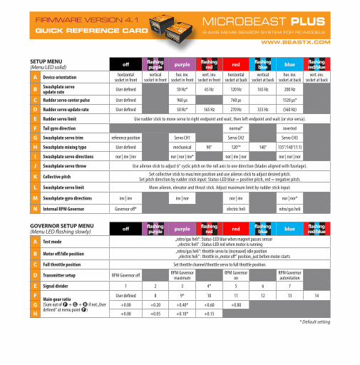
SETUP MENU (Menu LED solid) off flashing
purple purple flashing red red flashing
blue blue flashingred/blue
A Device orientation horizontalsocket in front
verticalsocket in front
hor. inv.socket in front
vert. inv.socket in front
horizontalsocket at back
verticalsocket at back
hor. inv.socket at back
vert. inv.socket at back
B Swashplate servoupdate rate User defined 50 Hz* 65 Hz 120 Hz 165 Hz 200 Hz
C Rudder servo center pulse User defined 960 μs 760 μs 1520 μs*
D Rudder servo update rate User defined 50 Hz* 165 Hz 270 Hz 333 Hz (560 Hz)
E Rudder servo limit Use rudder stick to move servo to right endpoint and wait, then left endpoint and wait (or vice versa).
F Tail gyro direction normal* inverted
G Swashplate servo trim reference position Servo CH1 Servo CH2 Servo CH3
H Swashplate mixing type User defined mechanical 90° 120°* 140° 135°/140°(1:1)
I Swashplate servo directions nor | inv | inv nor | nor | inv* nor | inv | nor nor | nor | nor
J Swashplate servo throw Use aileron stick to adjust 6° cyclic pitch on the roll axis to one direction (blades aligned with fuselage).
K Collective pitch Set collective stick to max/min position and use aileron stick to adjust desired pitch.Set pitch direction by rudder stick input: Status-LED blue = positive pitch, red = negative pitch.
L Swashplate servo limit Move aileron, elevator and thrust stick. Adjust maximum limit by rudder stick input.
M Swashplate gyro directions inv | inv inv | nor nor | inv nor | nor*
N Internal RPM Governor Governor off* electric heli nitro/gas heli
GOVERNOR SETUP MENU (Menu LED flashing slowly) off flashing
purple purple flashing red red flashing
blue blue flashingred/blue
A Test mode „nitro/gas heli“: Status-LED blue when magnet passes sensor„electric heli“ : Status-LED red when motor is running
B Motor off/Idle position „nitro/gas heli“: throttle servo to (increased) idle position „electric heli“ : throttle in „motor off“ position, just before motor starts
C Full throttle position Set throttle channel/throttle servo to full throttle position.
D Transmitter setup RPM Governor off RPM Governor maximum
RPM Governor on
RPM Governor autorotation
E Signal divider 1 2 3 4* 5 6 7
FMain gear ratio(Sum out of F + G + H if not „User defined“ at menu point F)
User defined 8 9* 10 11 12 13 14
G +0.00 +0.20 +0.40* +0.60 +0.80
H +0.00 +0.05 +0.10* +0.15
* Default setting
WWW.BEASTX.COM
QUICK REFERENCE CARD
FIRMWARE VERSION 4.1
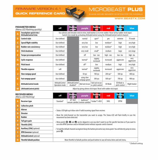
PARAMETER MENU (Menu LED flashing quickly) off flashing
purple purple flashing red red flashing
blue blue
A Swashplate quick trim /AttitudeControl trim
Use aileron and elevator stick to trim, hold button 2s to trim rudder. Reset all by rudder stick input.Switch trim mode by activating AttitudeControl using the AttitudeControl switch channel.
B Control style User defined normal sport* pro extreme TX mode
C Speed flight stability User defined very low low medium* high very high
D Rudder rate consistency User defined very low low medium* high very high
E Stick deadzone User defined very small small* medium large very large
F Torque precompensation User defined off low - nor. high - nor. low - inv. high - inv.
G Cyclic response User defined normal* slightly increased increased aggressive
veryaggressive
H Pitch boost User defined off* low medium high very high
I Throttle response soft normal* slightly increased increased aggressive
veryaggressive
J Slow rampup speed User defined 50 rps 100 rps 200 rps* 300 rps 400 rps
K Fast rampup speed User defined using slow rampup speed 300 rps 500 rps* 700 rps 900 rps
L AttitudeControl mode AttitudeControl Operation mode
AttitudeControl disabled* Bail out rescue Bail out rescue
w. pitch control 3D Mode 3D Mode w. pitch control Flight trainer
M (AttitudeControl pitch) Adjust by giving aileron stick input. Reset with rudder stick input.
RECEIVER MENU (Menu LED flashing) off flashing
purple purple flashing red red flashing
blue blue
A Receiver type Standard* JR® RJ01remote satellite
Spektrum® remote satellite Futaba® S-BUS SRXL SPPM
B Collective pitch
• Status-LED light up in blue color if valid incoming signal from receiver.
• Move the stick/channel on the transmitter you want to assign. The Status-LED will flash briefly in case the movement has been detected.
• Menu points H, I and J can be skipped in case you don‘t want to use the specific function or if you want to use nitro RPM Governor and/or AttitudeControl without separate switch channel.
• To load the default channel assingment keep the button pressed at any menu point. You will directly jump to menu point N.
C Aileron
D Elevator
E Rudder
F Tail gyro gain
G Throttle [CH5]
H Auxiliary [CH6] (optional)
I RPM Governor (optional)
J AttitudeControl (optional)
N Throttle failsafe position Move throttle to failsafe position and push button to save all menu items and exit menu.
* Default setting

SAFETY NOTES
• Radio controlled (R/C) helicopters are no toys! The rotor blades rotate at high speed and pose potential risk. They may cause severe injury due to improper usage. It is necessary to observe common safety rules for R/C models and the local law. You can gather information from your local R/C model club or from your national modelers association.
• Pay attention to your own safety and the safety of other people and property in your vicinity when using our product. Always fly in areas away from other people. Never use R/C models in close proximity to housing areas or crowds of people. R/C models may malfunction or crash due to several reasons like piloting mistakes or radio interference, and cause severe accidents. Pilots are fully responsible for their actions, and for damage or injuries caused by the usage of their models.
• Please read the following instructions thoroughly before the first use of your MICROBEAST PLUS and setup the system carefully according to this manual. Allow sufficient time for the setup procedure and check each step carefully. Watch for a mechanically clean and proper build of your helicopter. A wrong system setup can lead to a serious accident and damage to the model.
• Radio controlled (R/C) models consist of several electrical components. It is therefore necessary to protect the model from moisture and other foreign subtances. If the model is exposed to moisture this may lead to a malfunction which may cause damage to the model or a crash. Never fly in the rain or extremely high humidity.
• When operating the helicopter with a MICROBEAST PLUS ensure there is a sufficiently large and stable receiver power supply. Because of the direct coupling of the rotor blades to the servos, without the use of a flybar mixer, the servos are exposed to increased actuating forces. In addition, because of the intermediary electronic gyro system, the servos are driven more often than with traditional use. These factors can make the power consumption increase a lot compared to a flybar helicopter. When the supply voltage falls below 3.5 volts for a short amount a of time, the system will power off and reboot. In this case a crash of the helicopter is unavoidable.
• Do not expose the MICROBEAST PLUS system to extreme variations in temperature. Before powering up the system, wait some time so that the electronics can acclimatize and any accumulated condensation is able to evaporate.
• The sensors of MICROBEAST PLUS consist of highly sensitive electromechanical components. These can be damaged due to moisture or mechanical or electrical impact. Do not continue using this product, if it has been exposed to such influences, e.g. due to a crash of the model or due to overvoltage caused by a defective receiver power supply. Otherwise a failure may happen any time.
• When operating electric helicopters make sure that the electric motor cannot start inadvertently during the setup procedure. Particularly pay attention if using a single-line receiver and if the ESC is connected directly to the MICROBE AST PLUS. We recommend disconnecting the electric motor from the ESC during the setup procedure. Prior the first usage please slide the motor/pinion away from the main gear, then check that the motor does not to start inadvertently when the receiver is switched on.

• When operating the RPM Governor feature of MICROBEAST PLUS it is essential to ensure that the motor cannot start by accident when making adjustment or performing preparations to start the engine. Carefully read this manual and make sure you fully understand how the RPM Governor feature is operated before making any adjustments. Also make sure the motor does not start when the radio link is interrupted or when you switch on the transmitter initially. With electric driven models do not dock the motor to the main gear unless all necessary adjustment procedures have been finished. Always maintain sufficient safety distance to the motor and other rapidly rotating components of the helicopter.
• MICROBEAST PLUS with AttitudeControl can be used as a flying aid for beginners by limiting the reaction of the helicopter to stick inputs and by stabilizing the helicopter with a electronic control loop. However, this does not provide that the helicopter can always be flown safely! By incorrect control inputs the helicopter still may crash or be placed in a position in which the pilot becomes disoriented even when using AttitudeControl. In addition, the helicopter can drift due to external influences and it is not guaranteed that the artificial horizon of the device can stabilize the helicopter at any time and recover from any orientation. Influences such as temperature fluctuations or vibrations may cause incorrect results and distort the position calculation of the system in consequence. There is no guarantee that the system will always work correctly. Only the pilot is responsible for the control of the helicopter and thus also for the use of the system. Note that the system for technical reasons will not hold the helicopter absolutely to the point. The unstable tendency of a helicopter will cause the model to fly in a certain direction even when using AttitudeControl. External influences such as wind can further strengthen this effect. In addition measurement inaccuracies of the sensors can distort the position determination slightly. You must always be able to turn off the system immediately and be able to take over full control of the helicopter.
• We suggest you to seek the support of an experienced helicopter pilot before you undertake the first flight of your model. Additionally, flight training with a R/C simulator can help make flying easier and more enjoyable. Ask your local dealer if you need technical support or if you observe problems during the usage of our system.
• AttitudeControl can help to facilitate flying of model helicopters by briefly passing over control to the system if the pilot becomes disoriented. By using the built-in artificial horizon the helicopter can be brought to a nearly horizontal position so that the pilot gains time to reorient. Thus, there can be no assurance that the model is saved from a crash in general. Depending on the current attitude and the speed of the model and depending on how fast the AttitudeControl is activated, the model may crash before or while the system tries to recover. In addition, the helicopter can drift due to external influences and it is not guaranteed that the artificial horizon of the device can stabilize the helicopter at any time and recover from any orientation. Influences such as temperature fluctuations or vibrations may cause incorrect results and distort the position calculation of the system in consequence. Strictly observe the general safety rules for dealing with RC models and do not totally rely on the system. The pilot is responsible for the control of the helicopter and thus also for the use of the system. You must always be able to turn off the system immediately and be able to take over full control of the helicopter.
SAFETY NOTES

4115
STUDIOX.BEASTX.COM BEASTX.COM WIKI.BEASTX.COM