QuickScan 2000 WIN Version 2 - Helena Laboratories Manuals/Quickscan WIN 2 Op... · QuickScan 2000...
149
QuickScan 2000 WIN Version 2 Visible Scanning Densitometer Operator's Manual Catalog Numbers 1660, 1661, 1662, 1663, 1673, 1678, and 1679
Transcript of QuickScan 2000 WIN Version 2 - Helena Laboratories Manuals/Quickscan WIN 2 Op... · QuickScan 2000...

QuickScan 2000 WIN Version 2
Visible Scanning Densitometer
Operator's Manual Catalog Numbers 1660, 1661, 1662, 1663, 1673, 1678, and 1679

QuickScan 2000 WIN Version 2
Visible Scanning Densitometer
Operator’s Manual

WARNING! DO NOT ATTEMPT TO MOVE, INSTALL, OR OPERATE
THIS INSTRUMENT BEFORE READING AND UNDERSTANDING THE CONTENTS OF THIS MANUAL,
PARTICULARLY THE PRECAUTIONS, LIMITATIONS AND HAZARDS IN SECTIONS THREE AND FOUR.
QuickScan 2000 WIN Program License Agreement
This copy of the QuickScan 2000 WIN program is sold on the condition that the purchaser agrees to the terms of this license agreement. If not, the purchaser should return the un-opened diskette package to Helena Laboratories to obtain a refund. Retention of the product will constitute acceptance of this license.
1. Helena Laboratories Corp. (Helena) warrants to the ORIGINAL PURCHASER ONLY (Pur-chaser) that the diskette on which the computer program is contained shall be free of defects in materials and workmanship under normal use for 6 months from the date of purchase. Helena will repair or, at its option, replace any defective diskette returned to the address below during the 6-month period.
2. THIS IS THE ONLY WARRANTY MADE BY HELENA COVERING THE QUICKSCAN 2000 WIN PROGRAM. THE COMPUTER PROGRAM AND THE ENCLOSED INSTRUCTIONAL MATERIALS ARE SOLD “AS IS”, WITHOUT ANY WARRANTY OF ANY KIND, EXPRESSED OR IMPLIED, INCLUDING BUT NOT LIMITED TO: ANY WARRANTY OF PERFORMANCE, MERCHANTABILITY, OR FITNESS FOR A PARTICULAR PURPOSE. PURCHASER ASSUMES ALL RISKS AS TO THE PERFORMANCE AND RESULTS OF THE PROGRAM. IN NO EVENT WILL HELENA OR ITS SUPPLIERS BE LIABLE FOR ANY INCIDENTAL, CONSEQUENTIAL OR OTHER DAMAGES, INCLUDING BUT NOT LIMITED TO ANY DAMAGES ARISING FROM USE OR MISUSE OF THE PROGRAM.
3. This computer program is for the use of purchaser only, and only on the computer system specified. No part of the program may be reproduced, nor may any part of the program be utilized in or transferred to any information storage and retrieval system of electronic or me-chanical medium without prior written permission of Helena. Purchaser may make up to two back-up copies of the program for Purchaser’s personal use only, and should forward any questions concerning reproduction or transfer of the program, and requests for permission to do so, to Helena Laboratories, P.O. Box 752, Beaumont, TX 77704-0752. Any noncompliance with this paragraph will result in termination of this license, and may also result in legal liability under U.S. copyright laws.
4. Use of this program constitutes acceptance of the terms and conditions of this agreement.
© November, 2012 Helena Laboratories Helena Laboratories 1530 Lindbergh Dr./P.O. Box 752
Beaumont, Texas 77704 USA Telephone (409) 842-3714

QUICKSCAN 2000 WIN Table of Contents
-i-
List of Sections
Section 1 - Instrument Use and Function............................................................................1-1
Section 2 - Principles of Operation......................................................................................2-1 2.1. Transmittance Densitometry.........................................................................................2-1 2.2. References ...................................................................................................................2-1 2.3. Other Aspects of Operation ..........................................................................................2-1
Section 3 - Precautions and Limitations .............................................................................3-1
Section 4 - Hazards ...............................................................................................................4-1
Section 5 - Installation ..........................................................................................................5-1 5.1. Unpacking and Inspection ............................................................................................5-1 5.2. Select Instrument Location ...........................................................................................5-2 5.3. Component Interface and Power Connections .............................................................5-2
5.3.1. Computer ...............................................................................................................5-2 5.3.2. Printer ....................................................................................................................5-2 5.3.3. Scanner..................................................................................................................5-3 5.3.4. Monitor ...................................................................................................................5-3 5.3.5. Keyboard................................................................................................................5-3 5.3.6. Mouse ....................................................................................................................5-3 5.3.7. Power Connections ................................................................................................5-3
5.4. Powering Up and Scanner Parameter Installation ........................................................5-3 5.4.1. Components...........................................................................................................5-3 5.4.2. Computer ...............................................................................................................5-4 5.4.3. Installing Scanner Parameters ...............................................................................5-4 5.4.4. Opening/Starting QuickScan 2000 Software..........................................................5-4
5.5. Helpful Hints .................................................................................................................5-4 5.5.1. Mouse ....................................................................................................................5-4 5.5.2. Keyboard................................................................................................................5-4 5.5.3. QuickScan 2000 WIN Displays and Manual...........................................................5-4
5.6. Verification of Functionality...........................................................................................5-5 5.7. Programming Setup......................................................................................................5-5
Section 6 - User Setup ..........................................................................................................6-1 6.1. Tests.............................................................................................................................6-1
6.1.1. Tests Setup ............................................................................................................6-1 6.1.1.1. Default Test Parameters..................................................................................6-1 6.1.1.2. Customizing/Altering Test Parameters ............................................................6-2
6.1.1.2.1. Test Properties..........................................................................................6-2 6.1.1.2.2. Scan Setup ...............................................................................................6-3 6.1.1.2.3. Reference Ranges ....................................................................................6-6
6.1.2. Tests Print Setup....................................................................................................6-7 6.2. Worklists .......................................................................................................................6-7
6.2.1. Worklist Setup ........................................................................................................6-7

QUICKSCAN 2000 WIN Table of Contents
-ii-
6.2.1.1. Label................................................................................................................6-8 6.2.1.2. Activity .............................................................................................................6-8 6.2.1.3. Tasks (Scan Tasks or Retrieve Tasks) ............................................................6-9
6.2.1.3.1. Edit............................................................................................................6-9 6.2.1.3.2. Display Settings ........................................................................................6-9 6.2.1.3.3. Print.........................................................................................................6-10 6.2.1.3.4. Print Settings...........................................................................................6-10
6.2.1.3.4.1. Printer...............................................................................................6-10 6.2.1.3.4.2. Report ..............................................................................................6-10
6.2.1.3.5. Export......................................................................................................6-11 6.2.1.3.6. Export Settings........................................................................................6-11 6.2.1.3.7. Save........................................................................................................6-12 6.2.1.3.8. Delete......................................................................................................6-12 6.2.1.3.9. OK...........................................................................................................6-12
6.2.2. Worklist Print Setup..............................................................................................6-12 6.3. Demographics ............................................................................................................6-13
6.3.1. Demographics Setup............................................................................................6-13 6.3.2. Demographic Print Setup .....................................................................................6-14
6.4. Reports .......................................................................................................................6-14 6.4.1. Reports Setup ......................................................................................................6-14
6.4.1.1. Label..............................................................................................................6-15 6.4.1.2. Type...............................................................................................................6-15 6.4.1.3. Scans per Report...........................................................................................6-15 6.4.1.4. Size and Orientation ......................................................................................6-15 6.4.1.5. Add ................................................................................................................6-15 6.4.1.6. Modify ............................................................................................................6-16
6.4.1.6.1. Modify Scan Identifier Component ..........................................................6-16 6.4.1.6.2. Modify Patient Information Component ...................................................6-17 6.4.1.6.3. Modify Sample Image Component ..........................................................6-17 6.4.1.6.4. Modify Graph Component .......................................................................6-17 6.4.1.6.5. Modify Overlay Legend Component........................................................6-17 6.4.1.6.6. Modify IFE Overlay: Scan Identifier Component .....................................6-18 6.4.1.6.7. Modify IFE Overlay: Image Component ..................................................6-18 6.4.1.6.8. Modify IFE Overlay: Results Component ................................................6-18 6.4.1.6.9. Modify IFE Overlay: Interpretation Component .......................................6-19 6.4.1.6.10. Modify IFE Overlay: Auto Interpretation Component.............................6-19 6.4.1.6.11. Modify Scan Status Component............................................................6-19 6.4.1.6.12. Modify Results Component ...................................................................6-20 6.4.1.6.13. Modify Comments Component..............................................................6-20 6.4.1.6.14. Modify Auto Interpretation Component..................................................6-20 6.4.1.6.15. Modify Text Component ........................................................................6-21 6.4.1.6.16. Modify Picture Component....................................................................6-21 6.4.1.6.17. Modify Line Component ........................................................................6-21 6.4.1.6.18. Modify Levey-Jennings Graph Component ...........................................6-21 6.4.1.6.19. Modify Table Component ......................................................................6-21
6.4.1.7. Cut, Copy, Paste, Undo, Print, and Clear ......................................................6-22
QUICKSCAN 2000 WIN Table of Contents
-iii-
6.4.1.8. OK and Cancel ..............................................................................................6-22 6.4.2. Reports Print Setup..............................................................................................6-22
6.5. Comment / Interpretation ............................................................................................6-22 6.5.1. Comment / Interpretation Setup ...........................................................................6-22 6.5.2. Comment / Interpretation Print Setup...................................................................6-23
6.6. Import / Export ............................................................................................................6-24 6.6.1. Import / Export Setup ...........................................................................................6-24
6.6.1.1. Host Computer ..............................................................................................6-24 6.6.1.2. Export File .....................................................................................................6-25 6.6.1.3. E-mail ............................................................................................................6-25
6.6.2. Import / Export Print Setup...................................................................................6-26 6.7. Archive........................................................................................................................6-27
6.7.1. Archive Setup.......................................................................................................6-27 6.7.2. Archive Print Setup ..............................................................................................6-27
6.8. QC ..............................................................................................................................6-27 6.8.1. QC Setup .............................................................................................................6-27 6.8.2. QC Print Setup .....................................................................................................6-28
6.9. Scanner ......................................................................................................................6-28 6.9.1. Scanner Setup .....................................................................................................6-28 6.9.2. Scanner Print Setup .............................................................................................6-29
6.10. Printer Setup.............................................................................................................6-29 6.11. Date and Time Setup................................................................................................6-29 6.12. Password Setup .......................................................................................................6-30 6.13. Backup......................................................................................................................6-30 6.14. Restore .....................................................................................................................6-30
Section 7 - Operating Instructions.......................................................................................7-1 7.1. Summary Instructions ...................................................................................................7-1
7.1.1. Summary for a Scan Worklist.................................................................................7-1 7.1.2. Summary for a Retrieve Worklist............................................................................7-1 7.1.3. Editing Summary....................................................................................................7-1 7.1.4. Saving and Exporting Summary.............................................................................7-2 7.1.5. Reports Printing Summary .....................................................................................7-2
7.2. File................................................................................................................................7-2 7.2.1. Open/Close/Select Worklist....................................................................................7-2 7.2.2. Retrieve from File / Retrieve Scan(s) from Archive ................................................7-2
7.2.2.1. Search, Retrieve, Cancel and Reset Buttons ..................................................7-3 7.2.2.2. Search .............................................................................................................7-3
7.2.2.2.1. Source and Properties ..............................................................................7-3 7.2.2.2.2. Basic Search.............................................................................................7-3 7.2.2.2.3. Advanced Search......................................................................................7-4 7.2.2.2.4. Reference, Normal, Abnormal, Today, Yesterday, This Month, Last Month, and Clear Buttons .....................................................................................................7-4
7.2.2.3. Retrieve Tasks.................................................................................................7-4 7.2.3. Retrieve from E-mail / Retrieve Scan(s) from E-mail..............................................7-5 7.2.4. Print Scan(s) ..........................................................................................................7-6
7.2.4.1. Print Settings ...................................................................................................7-6

QUICKSCAN 2000 WIN Table of Contents
-iv-
7.2.4.1.1. Printer .......................................................................................................7-6 7.2.4.1.2. Report .......................................................................................................7-6 7.2.4.1.3. Ok and Cancel ..........................................................................................7-7
7.2.4.2. Select Scans to Print .......................................................................................7-7 7.2.4.3. Print and Cancel ..............................................................................................7-7
7.2.5. Export Scan(s) .......................................................................................................7-7 7.2.5.1. Export Settings ................................................................................................7-7
7.2.5.1.1. Destination ................................................................................................7-8 7.2.5.1.2. Demographics...........................................................................................7-8 7.2.5.1.3. Graphics....................................................................................................7-8 7.2.5.1.4. Comments.................................................................................................7-8 7.2.5.1.5. Results ......................................................................................................7-8 7.2.5.1.6. Ranges......................................................................................................7-8 7.2.5.1.7. Ok and Cancel ..........................................................................................7-8
7.2.5.2. Select Scans to Export ....................................................................................7-8 7.2.5.3. Export and Cancel ...........................................................................................7-8
7.2.6. Save Scan(s)..........................................................................................................7-9 7.2.7. Clear Worklist.........................................................................................................7-9 7.2.8. Exit .......................................................................................................................7-10
7.3. Edit .............................................................................................................................7-10 7.3.1. Patient Info/Enter Patient Info ..............................................................................7-10
7.3.1.1. Patient Identification ......................................................................................7-11 7.3.1.2. Patient Management .....................................................................................7-11
7.3.2. Edit Scan(s)..........................................................................................................7-12 7.3.2.1. Delimit Bands ................................................................................................7-13 7.3.2.2. Delete Area....................................................................................................7-14 7.3.2.3. Baseline Correction .......................................................................................7-14 7.3.2.4. Overlay ..........................................................................................................7-14
7.3.2.4.1. Unedited..................................................................................................7-14 7.3.2.4.2. Reference ...............................................................................................7-14 7.3.2.4.3. Patient.....................................................................................................7-15
7.3.2.5. Appearance ...................................................................................................7-15 7.3.2.6. Input / Output.................................................................................................7-16
7.3.2.6.1. Patient Info..............................................................................................7-16 7.3.2.6.2. Comments...............................................................................................7-16 7.3.2.6.3. Auto Interpretation...................................................................................7-16 7.3.2.6.4. Print, Export and Save ............................................................................7-17
7.3.2.7. Restore ..........................................................................................................7-17 7.3.2.8. Edit IFE Scans...............................................................................................7-17
7.3.2.8.1. Appearance.............................................................................................7-17 7.3.2.8.2. Input / Output ..........................................................................................7-17
7.3.3. User Setup ...........................................................................................................7-18 7.4. Scan ...........................................................................................................................7-18
7.4.1. Scan New Gel ......................................................................................................7-18 7.4.2. Rescan Previous Gel ...........................................................................................7-19 7.4.3. Options/Scan Options ..........................................................................................7-19

QUICKSCAN 2000 WIN Table of Contents
-v-
7.4.4. QC........................................................................................................................7-21 7.5. View............................................................................................................................7-22
7.5.1. Display Options/Set Display Options....................................................................7-22 7.5.2. Error Log ..............................................................................................................7-23 7.5.3. Trace Log.............................................................................................................7-23 7.5.4. Memory Status .....................................................................................................7-23 7.5.5. OS Information .....................................................................................................7-23
7.6. Windows .....................................................................................................................7-23 7.6.1. Cascade...............................................................................................................7-23 7.6.2. Tile .......................................................................................................................7-23 7.6.3. Arrange Icons.......................................................................................................7-23 7.6.4. Close All ...............................................................................................................7-24 7.6.5. List of Open Worklists ..........................................................................................7-24
7.7. Help ............................................................................................................................7-24 7.7.1. About....................................................................................................................7-24
7.8. Arrows ........................................................................................................................7-24 7.9. Tips.............................................................................................................................7-24
7.9.1. Scanning ..............................................................................................................7-24 7.9.1.1. Edit Pathological ............................................................................................7-25 7.9.1.2. Reference Ranges and Reference Overlays .................................................7-25 7.9.1.3. Editing............................................................................................................7-25 7.9.1.4. Urine and Serum Proteins .............................................................................7-25 7.9.1.5. Cholesterol profiles ........................................................................................7-26 7.9.1.6. QuickGel........................................................................................................7-26 7.9.1.7. Fetal Tek........................................................................................................7-26 7.9.1.8. IFE.................................................................................................................7-26 7.9.1.9. Hemoglobins..................................................................................................7-26
7.9.2. Why My Scans Are Displayed This Way and How to Change Them ...................7-27 7.9.2.1. One Scan At A Time Displayed .....................................................................7-27 7.9.2.2. Multiple Scans Displayed...............................................................................7-27
7.9.3. Patient Overlays...................................................................................................7-27 7.9.4. How To Print a Serum Protein and IFE Scan On One Report..............................7-28
7.10. Results......................................................................................................................7-28
Section 8 - Test Functions and Quality Control..................................................................8-1 8.1. Tests.............................................................................................................................8-1 8.2. Quality Control ..............................................................................................................8-1 8.3. Instrument Performance Check ....................................................................................8-1
Section 9 - Performance Specifications ..............................................................................9-1 9.1. General Specifications..................................................................................................9-1 9.2. User Programming........................................................................................................9-1
9.2.1. Programming Test..................................................................................................9-2 9.2.2. Programming Worklists ..........................................................................................9-2 9.2.3. Programming Report Style .....................................................................................9-2 9.2.4. Programming Patient Demographics .....................................................................9-2 9.2.5. Programming Comments .......................................................................................9-2

QUICKSCAN 2000 WIN Table of Contents
-vi-
9.3. Editing...........................................................................................................................9-2 9.4. File Retrieval.................................................................................................................9-2 9.5. Automatic Data Analysis, Each Scan............................................................................9-2 9.6. Densitometer Specifications .........................................................................................9-3
Section 10 - Maintenance, Troubleshooting, and Warranty ............................................10-1 10.1. Maintenance .............................................................................................................10-1
10.1.1. General Cleaning ...............................................................................................10-1 10.1.2. Cleaning Scanner Glass.....................................................................................10-1
10.2. Troubleshooting........................................................................................................10-2 10.3. Warranty ...................................................................................................................10-3
Section 11 - Symbology......................................................................................................11-1
Section 12 - Communication Specifications.....................................................................12-1
Section 13 - Reports............................................................................................................13-1
Section 14 - Icons................................................................................................................14-1
Section 15 - Flow Chart.......................................................................................................15-1
Section 16 - Index................................................................................................................16-1
List of Figures
Figure 1-1. QuickScan 2000 WIN System ...........................................................................1-2
Figure 2-1. Functional Units of the QuickScan 2000 WIN Block Diagram .......................2-3
Figure 2-2. Visible Scan Optics...........................................................................................2-3
Figure 5-1. Front view of the QuickScan 2000 WIN ...........................................................5-6
Figure 5-2. Back view of QuickScan 2000 WIN ..................................................................5-6
Figure 6-1. Main Menu........................................................................................................6-32
Figure 6-2. User Setup, Tests............................................................................................6-32
Figure 6-3. Setup Test, Test Properties............................................................................6-33
Figure 6-4. Setup Test, Scan Setup ..................................................................................6-33
Figure 6-5. Setup Test, Reference Range.........................................................................6-34
Figure 6-6. User Setup, Worklists .....................................................................................6-34
QUICKSCAN 2000 WIN Table of Contents
-vii-
Figure 6-7. Setup Worklist .................................................................................................6-35
Figure 6-8. Display Settings ..............................................................................................6-35
Figure 6-9. Print Settings...................................................................................................6-36
Figure 6-10. Export Settings..............................................................................................6-36
Figure 6-11. Setup Demographics ....................................................................................6-37
Figure 6-12. User Setup, Reports......................................................................................6-37
Figure 6-13. Setup Report (Type - Standard) ...................................................................6-38
Figure 6-14. Setup Report (Type - List and Statistics) ....................................................6-38
Figure 6-15. Setup Report (Type - Levey-Jennings)........................................................6-39
Figure 6-16. User Setup, Comments / Interpretations.....................................................6-39
Figure 6-17. Setup Comments / Interpretations...............................................................6-40
Figure 6-18. User Setup, Import / Export..........................................................................6-40
Figure 6-19. Setup Host Computer Interface ...................................................................6-41
Figure 6-20. Port Communications Settings....................................................................6-41
Figure 6-21. Setup Export File...........................................................................................6-41
Figure 6-22. Setup E-mail ..................................................................................................6-42
Figure 6-23. Setup Archive ................................................................................................6-42
Figure 6-24. Setup QC........................................................................................................6-43
Figure 6-25. Setup Scanner ...............................................................................................6-43
Figure 6-26. Print Setup .....................................................................................................6-44
Figure 6-27. Set Date and Time .........................................................................................6-44
Figure 6-28. Set Password.................................................................................................6-45
Figure 6-29. Backup User Setup .......................................................................................6-45
Figure 6-30. Restore User Setup.......................................................................................6-45
Figure 7-1. Main Menu........................................................................................................7-29

QUICKSCAN 2000 WIN Table of Contents
-viii-
Figure 7-2. Retrieve, Basic Search....................................................................................7-29
Figure 7-3. Retrieve, Advanced Search ............................................................................7-30
Figure 7-4. Worklist - Print..................................................................................................7-30
Figure 7-5. Print Settings...................................................................................................7-31
Figure 7-6. Worklist - Export .............................................................................................7-31
Figure 7-7. Export Settings................................................................................................7-32
Figure 7-8. Worklist - Save ................................................................................................7-32
Figure 7-9. Patient Information, Patient Identification ....................................................7-33
Figure 7-10. Patient Information, Patient Management...................................................7-33
Figure 7-11. Patient Search ...............................................................................................7-34
Figure 7-12. Edit Scan(s), Delimit Bands..........................................................................7-34
Figure 7-13. Edit Scan(s), Delete Area..............................................................................7-35
Figure 7-14. Edit Scan(s), Baseline Correction................................................................7-35
Figure 7-15. Edit Scan(s), Overlay ....................................................................................7-36
Figure 7-16. Select Patient Overlay...................................................................................7-36
Figure 7-17. Edit Scan(s), Appearance .............................................................................7-37
Figure 7-18. Edit Scan(s), Input/Output ............................................................................7-37
Figure 7-19. Edit Scan(s), Input/Output, Comments........................................................7-38
Figure 7-20. Retrieve Comment/Interpretation ................................................................7-38
Figure 7-21. Pattern Characteristic ...................................................................................7-38
Figure 7-22. Edit Scan(s), Restore ....................................................................................7-39
Figure 7-23. IFE Edit Scan(s), Appearance ......................................................................7-39
Figure 7-24. IFE Edit Scan(s), Input/Output .....................................................................7-40
Figure 7-25. Scan Options .................................................................................................7-40
Figure 7-26. QC...................................................................................................................7-41

QUICKSCAN 2000 WIN Table of Contents
-ix-
Figure 7-27. QC History .....................................................................................................7-41
Figure 7-28. Displays Settings ..........................................................................................7-42
Figure 13-1. Levey-Jennings Report.................................................................................13-1
Figure 13-2. List Report .....................................................................................................13-2
Figure 13-3. Standard Report ............................................................................................13-3
Figure 13-4. Statistics Report............................................................................................13-4
Figure 13-5. IFE Overlay Report ........................................................................................13-5
Figure 13-6. Two-Scan Standard Report ..........................................................................13-6
Figure 13-7. QC Results.....................................................................................................13-7
Figure 13-8. QC History Report .........................................................................................13-8
List of Tables
Table 5-1. Inventory..............................................................................................................5-1
Table 5-2. System Requirements .........................................................................................5-2
Table 10-1. Troubleshooting .............................................................................................10-2

QUICKSCAN 2000 WIN ONE - Instrument Use and Function
1-1
Section 1 - Instrument Use and Function
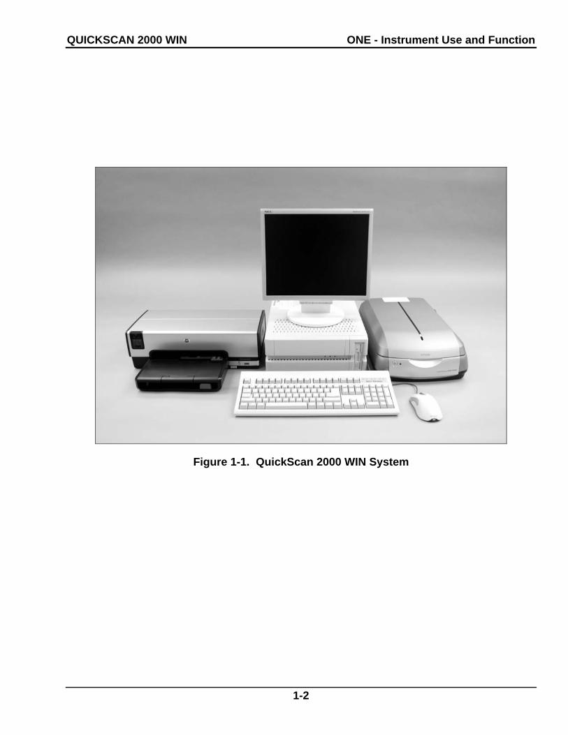
Helena’s QuickScan 2000 WIN (Figure 1-1) is a visible scanning densitometer used to scan electrophoretic gels, quantitate data, and display and print results. The QuickScan 2000 WIN is intended for in-vitro diagnostic use only, in a laboratory or similar environ-ment.
Visible sample gels are placed in the Quick-Scan 2000 WIN and scanned. Results for a number of different tests can then be viewed on the monitor and printed in a report.
A built-in computer directs all operations of the system. The system could include a CD drive, a Zip drive, a floppy disk drive, internal hard disk, a flatbed scanner, a color monitor, a printer, a mouse, and a keyboard.
Varieties of test types are preprogrammed in the QuickScan 2000 WIN. Presently, these tests are Serum and Urine Proteins using acid blue stain, Serum Proteins using Ponceau S stain, Alkaline Hemoglobins, Alkaline Phos-phatase, Cholesterol Profile, CK - Creatine Kinase, LD - Lactic Dehydrogenase, IFE - Immunofixation, L/S - Lecithin/Sphingomyelin and Lipoproteins. Parameters for up to 20 tests can be stored in the unit.
Stored results can be retrieved in seconds. Full editing features are provided so that fractions may be selected, baselines ad-justed, comments added to the file, etc. Up to 100 copies of a test report can be printed.
Refer to the procedure supplied with the gels for information on the following areas: Summary Principle Reagents Instruments Specimen Collection and Handling Step-by-Step Method Evaluation of the Bands Stability of End Product Results Expected Values
Performance Characteristics Interpretation of Results Bibliography
QUICKSCAN 2000 WIN ONE - Instrument Use and Function
1-2
Figure 1-1. QuickScan 2000 WIN System
QUICKSCAN 2000 WIN TWO - Principles of Operation
2-1
Section 2 - Principles of Operation
The QuickScan 2000 WIN program contains factory preset default values for scanning parameters. These values can be changed, permanently or temporarily. Refer to section six for programming instructions. If default parameters are altered, they can be rein-stalled as needed.
The functional units of the QuickScan 2000 WIN are shown in Figure 2-1.
2.1. Transmittance Densitometry
The visible mode optics configuration is shown in Figure 2-2. A lamp (1) provides white light which passes through the samples on the electrophoretic gel (2). The entire gel is scanned in one pass.
The amount of light passing through the sample is an inverse logarithmic function of sample density. For example, if the sample density is doubled, the transmitted light is reduced by a factor of ten.
The transmitted light falls on a CCD array (3), generating current in proportion to the amount of light hitting the sensors. This signal is stored in memory, and used by the computer to calculate the area under the curve for the various signal peaks, representing sample densities on the pattern.
The aperture size, selected by the user, mathematically determines the area of the scanned pattern used in calculations. If the aperture is too small, resolution will be high, but noisy or jagged patterns may result. If the aperture is too large, a smooth curve results, but resolution may be too low.
2.2. References
Control samples should be designated as Reference samples when the operator is using the Reference Overlay feature. This feature allows the program to overlay the Reference pattern over the sample pattern on the display or report, if desired.
2.3. Other Aspects of Operation
The computer directs all system operation according to the information contained in the memory and in response to commands from the user. The user makes selections from information on the Color Display using the keyboard or mouse. Access to the setup can be limited by use of a password.
Patient files can be duplicated and stored at the user’s option. The backup information can be restored to the memory should this become necessary. Excessive data slows the computer, so periodic archiving of data is recommended.
The computer uses the sensor signal level to calculate fraction data for each pattern. An analog graph of the data is produced, which the user can edit as desired. The peak areas are expressed as percentages, with integra-tion counts included if desired. When the total quantity in the sample is known, the quantity in each fraction can be determined.
When the results are displayed on the moni-tor, the user can elect to edit the pattern at that time, or later. If a printout is requested by the user, the printer produces a copy of the scan data and other user-entered information. Deviations in the results from reference ranges are indicated as high (+) or low (-) on the printout. All the data for each scan can be automatically stored on the hard disk. The user can also “export” data through a serial output port to an external computer and data can be emailed.
QuickScan 2000 WIN is completely prepro-grammed and is ready for use as is for the more common applications. However, scan parameters can be altered if so desired. All user input is through the mouse or keyboard. In normal use, the operator selects the type of test, enters patient demographics, places the gel in the scanner and starts or stops the automatic sequence of operations.

QUICKSCAN 2000 WIN TWO - Principles of Operation
2-2
The computer runs a self-test at power on to detect error conditions or potential problems. If an error is detected, the computer responds by displaying an error message (sec-tion 10.2).

QUICKSCAN 2000 WIN TWO - Principles of Operation
2-3
Keyboard
Mouse
Scanner
Printer
Monitor Display
Disk Drive(s)
ComputerCPU, Memory, Hard Drive
Figure 2-1. Functional Units of the QuickScan 2000 WIN Block Diagram
(1) White Light Source
(2) Gel
(3) CCD Array
Signal to Computer
Figure 2-2. Visible Scan Optics

QUICKSCAN 2000 WIN THREE - Precautions and Limitations
3-1
Section 3 - Precautions and Limitations
3.1. For emergency shutdown, turn off the instrument using the computer power switch or disconnect the main power cord from the wall outlet.
3.2. Do not attempt to move or operate the instrument until the entire Operator’s Manual, and the manuals provided with the scanner, monitor and printer, have been read and understood.
3.3. Keep the scanner lid closed. Do not place objects on the glass surface other than items to be scanned.
3.4. Always keep all glass surfaces in the scanner clean and dust free, or results may be compromised.
3.5. The instrument should be kept dust free if possible. No harsh cleansers, acids or bases should be used either inside or out. Do not immerse the unit. ALWAYS UNPLUG THE MAIN POWER CORD BEFORE CLEANING.
3.6. Should an instrument be contaminated by blood or blood derivatives, spray any contaminated surface with a commercial virucidal and germicidal agent. Observe where the specimens are used inside the instrument and confine cleaning to that area. Wipe up the residue. These materials contain alcohol, which is corrosive to metal surfaces.
3.7. Use only hardware and software acces-sories made specifically for the instrument.
3.8. Do not expose the instrument to drafts or operate the instrument in direct sunlight. Do not operate the instrument at tempera-tures below 59°F (15°C) or above 80.6°F (27°C), and do not allow prolonged exposure to high humidity.
3.9. Do not place the instrument near a strong source of electromagnetic interference, such as a centrifuge, x-ray machine, etc.
3.10. Use standard precautions when han-dling diskettes. Refer to the diskette jackets or inserts for appropriate precautions.
3.11. The diskette should be removed when not in use, to prevent damage.
3.12. Keep magnets away from diskettes or stored information may be lost. Do not place diskettes near a magnetic source or a strong source of electromagnetic interference.
3.13. Formatting a diskette, which already contains data, will erase the original data. Make sure that only a blank diskette, or one containing only unwanted data, is inserted into the instrument when formatting.
3.14. Installation should not be attempted unless a representative of Helena Laborato-ries or of its subsidiaries or distributors is present, or unless verbal or written permis-sion to proceed has been given by Helena Laboratories, its subsidiaries or distributors.
3.15. Although the QuickScan 2000 WIN is factory programmed for some procedures, you may alter scanning parameters if desired. If scanning problems occur, return to default parameters.
3.16. Provide adequate room at the sides and back of the instrument for good air circulation.
3.17. Use only gels and other media compati-ble with this system.

QUICKSCAN 2000 WIN FOUR - Hazards
4-1
Section 4 - Hazards
4.1. If the instrument is used in a manner not specified by this manual, the protection pro-vided by equipment design may be impaired.
4.2. Do not move the scanner until it is prepared for moving. See the scanner owner’s guide for instructions on moving the scanner. Failure to do so may result in dam-age to the scanner.
4.3. These devices contain high voltages, which can be extremely dangerous. Turn off the system power, disconnect the main power cord and use extreme care when attempting disassembly for cleaning, repair or adjust-ments. Do not operate any instrument with the cover off unless instructed to do so by a qualified service technician directly represent-ing Helena Laboratories, its subsidiaries, or its distributors.
4.4. Do not attempt to operate the instru-ment unless the power cords are plugged into grounded wall outlets of the proper voltage and frequency. This information is contained on the serial number plate located on the back of the instrument’s components.
4.5. Do not lubricate the instrument.

QUICKSCAN 2000 WIN FIVE - Installation
5-1
Section 5 - Installation
WARNING: Read sections three, Precau-tions and Limitations, and four, Hazards, before attempting to move, install, or operate the instrument.
5.1. Unpacking and Inspection
1. Check all shipping containers for signs of damage. If damage is found, immediately notify the shipping carrier.
2. Carefully unpack the instrument’s compo-nents and remove them from the shipping cartons. If possible, the packing material should be removed undamaged to facilitate repacking the instrument if it becomes necessary.
3. Remove the plastic wrappings from the components. If scissors or a knife are used to cut the plastic or binding tape, take care not to scratch the components.
4. Inventory all items (refer to the packing lists for a complete list of materials). If any parts are missing, recheck the packing materials before notifying Helena Laboratories.
Table 5-1. Inventory
1660 QuickScan 2000 (110V): 1 QuickScan 2000 WIN Software CD 1 Scanner Update CD 1 NDDC Plate 1 10 Step Optical Density Step Tablet 1 Key 1 QuickScan 2000 WIN Operator’s Manual 1 QuickScan 2000 WIN Field Installation Form 1 QuickScan 2000 WIN Computer
1 Mouse 1 Keyboard with interface cable 1 Power Cord
1 QuickScan 2000 WIN Scanner 1 Transparency Lid 1 USB Cable 1 Power Cord 1 Owner’s Guide
1 Color Monitor 1 Interface Cable 1 Power Cord 1 Owner’s Guide
1 Mouse Pad
1 Printer Interface Cable 1 Printer
1 Printer Toner Cartridge 1 Power Cord 1 Owner’s Guide
1661 QuickScan 2000, Export Version I: 1 QuickScan 2000 WIN Software CD 1 Scanner Update CD 1 NDDC Plate 1 10 Step Optical Density Step Tablet 1 Key 1 QuickScan 2000 WIN Operator’s Manual 1 Mouse Pad 1 Printer Interface Cable 1 Scanner Bed Template
1662 QuickScan 2000, Export Version II: 1 QuickScan 2000 WIN Software CD 1 Scanner Update CD 1 NDDC Plate 1 10 Step Optical Density Step Tablet 1 Key 1 QuickScan 2000 WIN Operator’s Manual 1 QuickScan 2000 WIN Field Installation Form 1 QuickScan 2000 WIN Scanner
1 Transparency Lid 1 USB Cable 1 Power Cord 1 Owner’s Guide
1 Mouse Pad 1 Printer Interface Cable
1663 QuickScan 2000, Export Version III: 1 NDDC Plate 1 10 Step Optical Density Step Tablet 1 Key 1 QuickScan 2000 WIN Operator’s Manual 1 Mouse Pad 1 Printer Interface Cable 1 Scanner Bed Template
1673 QuickScan 2000 Windows and Key 1 QuickScan 2000 WIN Software CD 1 Scanner Update CD 1 Key 1 QuickScan 2000 WIN Operator’s Manual
1679 QuickScan 2000 Software and Computer: 1 QuickScan 2000 WIN Software CD 1 Scanner Update CD 1 QuickScan 2000 WIN Operator’s Manual 1 QuickScan 2000 WIN Field Installation Form 1 QuickScan 2000 WIN Computer

QUICKSCAN 2000 WIN FIVE - Installation
5-2
1678 QuickScan 2000 Software: 1 QuickScan 2000 WIN Software CD 1 Scanner Update CD 1 QuickScan 2000 WIN Operator’s Manual 1 QuickScan 2000 WIN Field Installation Form 1 QuickScan 2000 WIN Software Installation
Instructions Letter
Table 5-2. System Requirements
Computer - IBM compatible PC, Pentium 300 MHz or higher, minimum 64MB of RAM, SVGA, minimum 2GB hard drive space, Microsoft® Windows® 2000 or Windows® XP operating systems (if network and/or internet connections will be used, the use of the latest security patch and service pack is recom-mended), modem, CD drive, and optional Zip and/or CD/RW drive.
Scanner - Epson models Expression 800, Expression 1600, Expression 1680, Perfec-tion 4870, Perfection 4990, or Perfection V700. Note that the Perfection 4870 or 4990 model scanners are not intended for use with L/S Fetal Tek plates.
Printer - any printer supported by Windows.
Monitor - any monitor supported by Windows.
5.2. Select Instrument Location
1. Select an environment free of drafts, direct sunlight, excessive humidity and dust, and large temperature fluctuations. Ambient temperature should be from 59° - 80.6°F (15° - 27°C).
2. Select an area with enough space to place the instrument’s components as shown in Figure 5-1.
3. Select a location close to the needed wall outlets. Grounded wall outlets must be of the proper voltage and frequency as described on the serial plates located on the back of the instrument’s components. The wall outlets should not be on the same circuit as any large load device such as a refrigerator, compressor, centrifuge, etc. The instrument’s circuitry contains filters to reduce the effect of line volt-age fluctuations. However, if the operator
experiences difficulty in operation, it may be necessary to install an isolation transformer. Transformer specifications are available from Helena Laboratories.
4. Do not select a location that places the instrument near a strong source of electro-magnetic interference, such as a centrifuge, x-ray machine, etc.
5.3. Component Interface and Power Connections
1. Check each component to make sure that each has the same power rating (110 to 120 VAC or 220 to 240 VAC). This information is located on the back of each component.
2. Check to ensure that the power switches are off on the instrument’s components.
3. When inserting interface cables into con-nectors, make sure that they are firmly seated. Route cables as shown in Figure 5-2.
5.3.1. Computer
1. Record the computer’s serial number located on the back of the computer for use later.
2. On the white Helena label containing a handwritten system serial number, located on the computer, write your Helena customer number.
3. Place the computer in the center of the area designated for the instrument (Figure 5-1). Keep in mind you will need access to the back of the computer to interface it with the other components.
4. Plug the female end of the computer’s power cord into the back of the computer (Figure 5-2).
5.3.2. Printer
1. Record the printer’s serial number located on the back of the printer for use later.
2. Place the printer relative to the computer, as shown in Figure 5-1.

QUICKSCAN 2000 WIN FIVE - Installation
5-3
3. Plug the provided Key into the bottom USB port on the back of the computer as shown in Figure 5-2.
4. Plug the printer interface cable into the back of the printer (Figure 5-2).
5. Plug the other end of the printer interface cable into one of the two USB ports on the back of the computer as shown in Figure 5-2.
6. Plug the female end of the printer’s power cord into the back of the printer (Figure 5-2).
7. For information on installing and removing toner or ink cartridges and on loading printer paper, see the printer owner’s guide.
5.3.3. Scanner
1. Record the scanner’s serial number located on the back of the scanner for use later.
2. On the white Helena labels containing a handwritten system serial number, one lo-cated on the scanner and one on the transparency lid, write your Helena customer number.
3. Attach the transparency lid to the scanner per the instructions included in the scanner owner’s guide.
4. Place the scanner relative to the computer, as shown in Figure 5-1.
5. Connect the USB cable to the scanner. Connect the other end of the USB cable to the top USB port on the back of the computer as shown in Figure 5-2. Unlock the scanner per the instructions included in the scanner owner’s guide.
6. If needed, plug the female end of the scan-ner’s power cord into the back of the scanner.
5.3.4. Monitor
1. Record the monitor’s serial number located on the back of the monitor for use later.
2. Place the monitor relative to the computer, as shown in Figure 5-1.
3. Plug the female end of the monitor’s power cord into the back of the monitor.
4. If needed, plug the monitor's interface cable into the matching receptacle on the back of the monitor (Figure 5-2).
5. Plug the monitor’s interface cable into the matching receptacle on the back of the com-puter. Hand tighten the thumbscrews.
5.3.5. Keyboard
1. Place the keyboard relative to the com-puter, as shown in Figure 5-1.
2. Plug the keyboard cable into the matching connector on the back of the computer.
5.3.6. Mouse
1. Place the mouse relative to the computer, as shown in Figure 5-1.
2. Plug the mouse cable into the receptacle on the back of the computer.
5.3.7. Power Connections
Once each component is interfaced and has its power cord, plug each power cord into a grounded wall outlet of the proper voltage and frequency. This information can be found on the serial number plates located on the back of the instrument’s components. Do not turn the power on at this time.
5.4. Powering Up and Scanner Parameter Installation
5.4.1. Components
With the components interfaced with the computer, turn each of the power switches on for the scanner, printer and monitor. The QuickScan 2000 WIN software will automati-cally setup all of the components for operation once the computer power is on. For additional information, refer to each component owner’s guide.

QUICKSCAN 2000 WIN FIVE - Installation
5-4
5.4.2. Computer
Once the scanner, printer and monitor are powered on, then turn on the computer’s power switch. The Windows program opens and displays the QuickScan 2000 WIN icon.
5.4.3. Installing Scanner Parameters
1. With the computer on and the QuickScan 2000 WIN software closed, insert the scanner parameters CD into the computer's CD drive.
2. Once the drive is closed, the installation automatically begins.
3. If installation does not automatically begin: a. Double click on the My Computer folder
on the computer desktop. b. Double click on the CD drive. c. Double click on the file SETUP.EXE. d. Once the Welcome window displays,
follow the displayed prompts to complete installation.
4. Once installation is complete, the Setup window closes.
5. Place the CD in the sleeve(s) located at the end of this manual.
6. To confirm the parameters for all the com-patible scanners are installed, see section 6.9.1 for instructions on accessing the list of scanner parameters installed.
5.4.4. Opening/Starting QuickScan 2000 Software
Select the QuickScan 2000 WIN icon. If the main menu (Figure 6-1) appears on the moni-tor, the system is operating correctly. If an error message appears instead, refer to section 10.2, Troubleshooting.
5.5. Helpful Hints
5.5.1. Mouse
The mouse may be used to make selections and indicate where information is to be en-tered. Move the white arrow, or a symbol
resembling a black Roman numeral one, , around the screen to the desired selection or location by moving the mouse over the mouse pad. With the white arrow over the desired area, click the button located on the left of the mouse. Clicking this button twice is required to select some options. In this manual, any statement to “click” or “double click” an area refers to these instructions. Any instruction to “select” something can be completed using the mouse.
5.5.2. Keyboard
The keyboard is used to enter information and in some areas to make selections. Any word displayed on the screen containing an underlined letter, for example Setup, can be accessed by simultaneously pressing the Alt key and the underlined letter key. In this manual, any keys listed with hyphens be-tween them, for example, Alt-S, need to be pressed simultaneously. On most screens, you can also access an area by pressing the Tab key until the desired area is indicated. The up, down, left, and right arrow keys can be used in areas where information is entered either to scroll through the areas available to enter information or to position your cursor within an indicated area.
5.5.3. QuickScan 2000 WIN Displays and Manual
In understanding this manual, keep the fol-lowing things in mind:
“click” or “double click” - refers to the instruc-tions given in section 5.5.1.
“field” - is the area into which information is entered.
“cursor” - refers to the location entered infor-mation will be placed and is most often indicated by a white arrow or a symbol re-sembling a black Roman numeral one, .
“drop down menu” or “drop down list” - refers to a list of options available for your selection.

QUICKSCAN 2000 WIN FIVE - Installation
5-5
A field has a drop down menu or list when the right side of the field has a square containing an arrow. You can access the drop down menu/list by clicking on the arrow or the field.
“highlight” or “highlighted” - refers to the information currently selected and is dis-played as white text with a blue background.
“slide” or “slide bar” - refers to when the display allows you to use either your mouse or your arrow keys to move an indicator bar in order to define the desired setting or access additional fields.
In this manual, Italic text refers to the display and bold text refers to keyboard keys.
5.6. Verification of Functionality
After reading and understanding the Opera-tor’s Manual, complete the applicable section of the Field Installation Verification Form QuickScan 2000 WIN as the following steps are performed:
1. Record on the verification form the serial numbers of each component recorded in section 5.3.
2. Record the software version and serial number. Refer to section 7.7.1 for instruc-tions on obtaining the software information.
3. Enter the QC values; see section 6.8.1. Perform a calibration QC; see section 7.4.4. Printout the QC results and include the print-out with the Verification Form.
4. Return the Verification Form as instructed on the form.
5.7. Programming Setup
The QuickScan 2000 WIN software is ready to operate once the desired test(s) and the worklist(s) are setup. Setup instructions are in Section 6 - User Setup.

QUICKSCAN 2000 WIN FIVE - Installation
5-6
Figure 5-1. Front view of the QuickScan 2000 WIN
Figure 5-2. Back view of QuickScan 2000 WIN *LIS (Laboratory Information System) or ESH (Electrophoresis Sample Handler)
Scanner
Mouse
Keyboard
Scanner Transparency Lid
Monitor
Computer
Printer
Printer InterfaceScanner Power
Cord
Monitor Interface
Transparency LidInterface Cable
Monitor Power Cord
Scanner Interface
Scanner Interface
Printer Power Cord
Mouse Interface
Keyboard Interface
CPU Power Cord
*LIS or ESH Port
Monitor Interface
Printer Interface
Key Interface

QUICKSCAN 2000 WIN SIX - User Setup
6-1
Section 6 - User Setup
Turn power on for the scanner, printer and monitor and then for the computer. The Microsoft® Windows® program opens and displays the QuickScan 2000 WIN icon. Select the icon. Take care to select the icon only once. Opening multiple copies may corrupt files. If the main menu (Figure 6-1) appears on the monitor, the system is operating correctly. If an error message appears instead, refer to section 10.2.
User Setup is accessed by selecting Edit on the main menu (Figure 6-1). A drop down menu displays; select User Setup. Note that access to User Setup can be controlled, at the users discretion, with a password, see section 6.12. If the User Setup Password: window displays, enter the password and select OK. The User Setup window (Figure 6-2) displays allowing for Setup, Print, Backup, and/or Restore to be used with the following features: Tests, Worklists, Demographics, Reports, Comments / Interpretations, Import / Export, Archive, QC, Scanner, Printer, Date and Time, and Password. The instructions on using Setup and Print (as applicable) are included in the following sections dedicated to each of the features. The instructions for using Backup and Restore are in sections 6.13 and 6.14, respectively. To most easily utilize the Quick-Scan 2000 WIN setup, it is recommended the features be setup in the following order:
Password (if applicable) - section 6.12 Scanner - section 6.9 Archive (if default file location needs to be altered) -
section 6.7 Date and Time - section 6.11 Printer - section 6.10 QC - section 6.8 Demographics - section 6.3 Tests - section 6.1 Import / Export (if applicable) - section 6.6 Reports (if the default reports need to be altered
and/or new reports created) - section 6.4 Comments / Interpretations (if a database of com-
ments is needed and/or auto interpretation is to be used) - section 6.5
Worklists - section 6.2
6.1. Tests
6.1.1. Tests Setup
The following instructions can be used to setup tests for the first time, setup user-defined tests, alter parameters of previously setup tests, and return a test to the default parameters. Up to twenty tests may be setup for use.
1. From the main menu (Figure 6-1), select Edit and then User Setup. If password is enabled, the User Setup Password window displays. Enter the password and select OK.
2. From the User Setup window (Figure 6-2), select Tests.
3. The right side of the window lists the names of any setup tests and the words [New Test]. Note that the [New Test] option is removed once twenty tests are setup. From this window select one of the following:
a. If a test using default parameters is be-ing setup for the first time, highlight [New Test], select Setup, and see section 6.1.1.1.
b. If a test has been setup but needs the default parameters reloaded, highlight the desired test, select Setup, and see section 6.1.1.1.
c. If a user-defined test is being setup for the first time, highlight [New Test], select Setup, and see section 6.1.1.2.
d. If a test has been setup but needs its parameters re-programmed, highlight the desired test, select Setup, and see section 6.1.1.2.
6.1.1.1. Default Test Parameters
1. From the Setup Test window (Figure 6-3), select Default.
2. The Load Default Test Parameters window contains a list of default tests. Highlight the desired test name and select OK. If no default is listed for the desired test, select

QUICKSCAN 2000 WIN SIX - User Setup
6-2
Cancel and see section 6.1.1.2. for instruc-tions on inputting user-defined test parameters. Duplicate tests may be setup; however, the Test Name must be altered for differentiation (section 6.1.1.2.1).
3. The Setup Test window now contains the default parameters specific to the test se-lected. Normally these parameters are used; however, operations can be customized by changing the parameters. Proceed, as needed, to one of the following:
a. To use the default parameters, no other parameters need to be altered, except when first setting up a test then the gel's scan begin and end positions should be set (sec-tion 6.1.1.2.2 step 6). Once the test is setup, select OK and the User Setup Test window displays the list of currently setup tests (Figure 6-2).
b. To customize the parameters, see sec-tion 6.1.1.2.
6.1.1.2. Customizing/Altering Test Parameters
Note that if scanning problems are encoun-tered after customizing parameters, the customized parameters can be altered or the default parameters can be reloaded. To reload the default parameters, see section 6.1.1.1.
The Setup Test window (Figure 6-3) contains three tabs titled Test Properties, Scan Setup and Reference Ranges. These tabs contain any parameters currently programmed for the selected test. Enter and/or alter parameters on these tabs, as needed according the following:
6.1.1.2.1. Test Properties
1. With the Setup Test window displayed, confirm the Test Properties tab is selected (Figure 6-3).
2. Test Name - may be entered/altered as needed and contain up to twenty characters.
The test name will automatically include the maximum number of samples and the stain type the test is setup to use plus the name entered in this field. Each test setup must have a unique Test Name. Note that for Cholesterol Profiles to have access to the Auto Edit and Report Total LDL features, the test name must include "Chol". Additionally, for Serum Proteins to have access to the Restricted Bands feature in the edit mode, the test name must include either "Proteins" or "SPE".
3. Gel Properties
a. Immunofixation Electrophoresis (IFE) - this option should only be selected for IFE imaging to create a copy of the individual patient gel image.
b. Rows per Gel - may be 1, 2, 3, 4 or 5.
c. Sample Application per Row - may be from 1 to 20.
d. Gel Stain Type - includes Acid Blue, Acid Violet, Amido Black, Fat Red 7B, Pon-ceau S, Neutral 1, and Neutral 2 and should only need customizing when entering a user-defined test. The stain type selected should match the color of the pattern scanned. Note that for Titan Gel Serum Protein gels, for better correlation with other Helena densi-tometers, select Acid Blue stain instead of Amido Black.
4. Results
a. Unit of Measure - may be any unit, ex-cept %, and can contain up to 10 characters, for example g/L, g/mL, U/L, U/dL.
b. Total Unit of Measure - is only available with Immunofixation Electrophoresis (IFE) selected. It may be any unit for proteins, for example g/L, g/mL, except %, and can con-tain up to 10 characters.
c. Decimal Places - select desired number of decimal places numeric results need to display containing, 0, 1, or 2.

QUICKSCAN 2000 WIN SIX - User Setup
6-3
d. Auto Interpretation - enables automatic interpretation of the scan results and requires user-defined interpretations be setup (sec-tion 6.5.1).
e. Report Total LDL (Lp(a) + LDL) - is only available when "Chol" is in the Test Name. Select this feature for the results to include the Total LDL value of Lp(a) plus LDL.
5. Labels
a. Ratio 1 and 2 - for each ratio setup (see step 7), enter a label of up to ten characters, for example A/G, L/S, etc.
b. Restricted Band - enter a label, of up to 12 characters (for example M-Spike or M-Protein) for use when a restricted band is marked.
6. Demographics - The only demographics accessible on this window are those desig-nated as Test type demographics during demographics setup (section 6.3.1). Test demographics are demographics which are not appropriate for use with all tests, for example Total. On this window, assign the label and type for any test specific demo-graphics the test being setup needs. As needed, use the vertical slide bar to view/access all ten demographics and setup the test demographics as follows:
a. Label - enter a label of up to twenty characters.
b. Type - select either Patient or Scan. A Patient demographic is one that will vary with each patient, such as birthdate or sex. A Scan demographic is one that will vary with each scan, such as draw date and time.
7. Fractions / Ratios - Total plus ten labels are available (nine labels if Immunofixation Electrophoresis (IFE) is selected). Default parameters contain default label titles, some of which contain default ratio assignments. As needed, use the vertical slide bar to view/access the Fractions / Ratios and setup as follows:
a. Label - titles may be entered/altered as needed and contain up to twelve characters. To have access to the Combine Split Beta feature, one label, other than the Total label, must be "Beta".
b. Ratio 1 and Ratio 2 - For each label, indicate the ratio assignments as N, for numerator, D, for denominator, or leave the space blank, to indicate it is neither. Each Label may be part of one, two or no ratios. For example, if the two ratios Total/HDL and LDL/HDL are desired, with HDL and LDL entered as labels, then for: Total Ratio 1 is N Ratio 2 is blank HDL Ratio 1 is D Ratio 2 is D LDL Ratio 1 is blank Ratio 2 is N
6.1.1.2.2. Scan Setup
1. Select the Scan Setup tab (Figure 6-4) and the top of the window will include the informa-tion in a. or b. as follows:
a. Scan Aperture - may be from 1 to 12, see section 9.6 for the measurement that corresponds to each aperture setting.
b. For IFE tests:
i. Channel Width (mm) - enter the nu-meric value of the channel width from 1 to 10. This is not related to spacing, it represents the width of the pattern that will be displayed on the window and is analogous to an aper-ture size in a standard scan. No units need be entered into this field.
ii. Channels per Sample - may be from 1 to 6 for Protein, IgG, etc.
2. Image Contrast - is set, using a slide bar, in a range of -10.0 Lighter to 10.0 Darker, in 0.2 increments. The setting affects only the appearance of the scan image when dis-played and printed and does not affect the quantitation.
3. Gain
a. Gain Mode:
i. Auto - the maximum fraction ampli-tude is set to 100% of the graph height with

QUICKSCAN 2000 WIN SIX - User Setup
6-4
the rest of the fraction heights proportional to it. Note that Serum Proteins are usually scanned in auto gain.
ii. Manual - the fraction amplitude is proportional to concentration and is the gain of choice for light patterns such as urines. This option is selected because an auto-scanned sample that is light will show many fractions. With Manual gain selected, Auto Scale is accessible in the Edit mode for use if a specific pattern over ranges because that pattern is not light. Patterns of varying inten-sity are usually scanned in Manual gain, for example, Urine Proteins and CK Isoenzymes.
1) Manual Gain - is set in a range of 0.0 Min to 10.0 Max, in 0.1 increments. Set using the slide bar accessible only when Manual is selected. Adjust the slide bar as needed to achieve the desired amplitude with the highest peak at the desired level when scanned. Start at a manual gain of five and increase or decrease gain as needed. Note that Manual Gain should be selected for Urine gels in order to minimize noise.
4. Fraction Detection
a. Sensitivity - sets the “sensitivity” of the instrument to +/- slope changes when detect-ing fractions. Set, using the slide bar, within a range of 0.0 Min to 10.0 Max, in 0.1 incre-ments. A sensitivity of zero turns off the auto fraction selector thus causing no fraction marks on the scan. Start at a sensitivity of four and increase or decrease as needed.
b. Forced Fractions - scanning using the Float or Fixed option is based on the as-sumption that the scan distance is the same for all rows. Any pattern may be named Reference to serve as a fraction mark guide as long as it is scanned before the scans to which it will be used. If using Float or Fixed, it is recommended that a representative sample of each row be identified as "Refer-ence".
i. No - select to pick fractions based only on pattern slope change.
ii. Float - select for fraction marks based on the pattern slope only if they occur within a window around the Reference frac-tion marks. If no fraction marks appear in the window, a mark is forced at the Reference fraction mark location. If selected, a sample will need to be labeled Reference for each gel (section 7.3.1) and will need to be scanned prior to any sample for which it will be the overlay. If Float is selected, then to more clearly see the impact on the scan, set the Worklist to Overlay Reference on the Display and/or Print Settings. An example of a use for the float feature is to force 5 frac-tions on a Urine Protein when a Serum is used as the Reference.
iii. Fixed - select to use the same frac-tion locations as those of a previously scanned Reference. If selected, a sample will need to be labeled Reference for each gel (section 7.3.1) and will need to be scanned prior to any sample for which it will be the overlay. The Fixed fractions feature is useful when the software would not normally insert marks where the operator desires. If Fixed is selected, then to more clearly see the impact on the scan, set the Worklist to Overlay Reference on the Display and/or Print Settings. This feature requires there be no pattern shift between the reference and the patterns. For this reason, either No or Float is usually the preferred choice.
5. Scan Tasks
a. Auto Slope Correction - select the soft-ware to automatically compare the scan baseline beginning and end and, if they are different, the software automatically makes a slope correction so that they are the same. This is a helpful feature for use with hemo-globins. Do not select this feature for use on L/S tests.
b. Smooth - Do not select unless the pro-cedure recommends otherwise; the graph will not be smoothed. Smoothing does affect the results. Increasing the smoothing level

QUICKSCAN 2000 WIN SIX - User Setup
6-5
decreases the background noise and lowers smaller fractions. Smoothing could affect small paraprotein spikes. This smoothing is applied when a gel is scanned and cannot be undone through the Edit mode; however, even with this smoothing option is use addi-tional smoothing can be done through the Edit mode.
i. Smoothing Level - is accessible with Smooth selected. Set a value from 1 to 10, with 1 being minimal smoothing and 10 being maximum smoothing.
c. Combine Split Beta - is only available for selection when, for Test Proprieties Frac-tions / Ratios, a label is titled "Beta" (section 6.1.1.2.1). With this feature selected, if the number of fractions is one greater than the number of fraction labels then the fraction that follows the "Beta" fraction and the "Beta" fraction are combined.
d. Auto Edit - is only available for tests with "Chol" in the test name (section 6.1.1.2.1). Note that if not selected in setup, Auto Edit is available for selection in the Edit mode. As an aid to scanning the auto edit program applies curvilinear analysis to the scans and marks the fractions appropriately. Only the fractions present will have fraction labels displayed or printed. The auto edited pattern may be modified by inserting a frac-tion mark but doing so looses the label identity so that all fractions labels will be used in order. Example: If a sample contains only HDL and LDL with auto edit selected only those labels will show on the screen and report with the cholesterol protein content divided between them. Insertion of a fraction mark between HDL and LDL will not alter curve interpretation but will add a label and override the original pattern fraction identifi-cation resulting in three fractions labeled HDL, Lp(a) and vLDL. The LDL fraction is now misidentified as vLDL. Addition of a second fraction mark results in 4 labels all correctly identified. With Auto Edit in use,
scans should be reviewed and can be edited, as needed, to evaluate the auto edit performance. Any sample without HDL should be restored. On some occasions, the HDL may be very low in value or may move faster causing the software to eliminate it. These patterns must be manually edited at the edit screen.
i. Auto Edit Settings - select and the Auto Edit Settings window displays and allows for selection of the following:
1) Cholesterol Auto Edit, Force Lp(a) Fraction - selection of this feature provides for automatic marking of an Lp(a) fraction, based on the Reference, if no Lp(a) is found during auto edit. The Lp(a) fraction is marked once HDL, LDL and, as applicable, vLDL are marked. In order to keep Lp(a) values on the report, the software marks automatically this small amount of Lp(a) based on an amount indicated by the Lp(a) area on the reference. If no vLDL is present, no fraction label will display/print. Caution: this feature is based on the absolute position of the Lp(a) on the reference. Opti-mally a reference may be put on each row of samples. These scans must always be reviewed because faulty fraction marking can compromise not only Lp(a) values but also HDL quantitation.
6. Scan Positions - to setup the scan begin and end positions and the sample to sample step over positions, proceed as follows:
a. Open the scanner lid.
b. Position the gel on the scanner: If scanning a Helena gel with a round and an obround hole, place the round hole over the right pin on the scanner and the obround hole over the left pin. If scanning a gel with no holes, place the gel so that the first sample is on the right, back corner of the scanner with the samples oriented left to right. If needed the gel may be taped down to the scanner bed to make it lie flat.

QUICKSCAN 2000 WIN SIX - User Setup
6-6
c. Close the lid.
d. Select Update Image. The scanner scans the gel and the message “Scanning in Progress” displays. An image of the gel displays under Scan Positions. For each row of the gel there is a green scan begin line, a red scan end line, a blue line to indicate the first sample position on the row, and a purple line to indicate the last sample position on the row.
e. For each row, use the mouse to move the green lines to the front of the pattern to set the scan begin and the red lines to the other end of the pattern to set the scan end. These lines should never overlap.
f. For each row, use the mouse to set the sample step over by placing the blue lines on the center of the samples located on the left of the window (the first sample) and placing the purple lines on the center of the samples located on the right of the window (the last sample). This operation defines the distance from one sample to the next. The purple line must be centered in the last sample position regardless of the number of samples in the row.
g. The QuickScan software will use the position of these lines to automatically calcu-late the space between each sample. This calculation is used to automatically setup the scanner so that all future scans of the same type test gel will use this as a preset scan begin, end and sample step over.
6.1.1.2.3. Reference Ranges
If no ranges for the test being setup need to be used, select OK and see step 8. Note that the default parameters for Cholesterol Profile 60 include Reference Range parameters based on NCEP Guidelines and can be altered when different ranges need to be used.
1. Select the Reference Range tab (Figure 6-5). Each range is setup in the same man-ner.
2. A B C D E F G H I - nine available refer-ence ranges. When using control ranges, the patient reference range is usually placed in range A, because this is the default range.
3. Range Type - Patient, Normal Control, and Abnormal Control. Note that Normal and Abnormal Control can only be used once per set of reference ranges. And if used, then a sample must be designated Reference Nor-mal or Reference Abnormal as appropriate.
4. Sex / Age Requirements - only available with Range Type Patient selected.
a. Sex - may contain only one character and is often used as the index for selection of range. For example, use M, for male, F, for female, or P, for Pediatric. The correspond-ing letter must be entered as sex when filling in patient demographics on the patient infor-mation window or range A will be selected. If the range is age specific, put no letter in the sex field.
b. Age Low and Age High - may be used for an age range. Place the lower limit, from 0 to 125, in the Age Low field and then select either Year(s), Month(s), or Day(s) from the drop down list in the field to the right. Place the upper limit, from 0 to 125, in the Age High field and select either Year(s), Month(s), or Day(s) from the drop down list in the field to the right.
5. Range Limits - enter the numeric range limits for the desired range types, percent and/or units. When range limits are in use, it is recommended that for all applicable work-lists the Display Settings options Display Percent and Display Percent Range and/or Display Units and Display Units Range be selected even if that information will not be printed or exported.

QUICKSCAN 2000 WIN SIX - User Setup
6-7
a. Fraction - includes Total and any labels assigned on the Test Properties tab for Frac-tions/Ratios (section 6.1.1.2.1). Total can also include a unit of measure in parenthe-ses, if with Immunofixation Electrophoresis (IFE) selected, a unit is entered in Total Unit of Measure.
b. Percent Range
i. Low Limit and High Limit - enter from 0.0 to 100.0 the percentages in numeric characters; however, do not include the % symbol. Enter the limits for all needed frac-tions.
c. Units Range - if, on the Test Properties tab, for Results, a Unit of Measure is entered (section 6.1.1.2.1), then Units is replaced with the entered Unit of Measure.
i. Low Limit and High Limit - enter from 0.0 to 99999.0 the units in numeric charac-ters; however, do not include the unit label. Enter the limits for all needed fractions.
d. Ratio Range
i. Labeled 1 and 2 or, if on the Test Properties tab, for Labels, Ratio labels are assigned (section 6.1.1.2.1), those labels replace 1 and/or 2.
ii. Low Limit and High Limit - Enter for each ratio label that is required. The limits can only be numeric characters from 0.0 to 99999.0 and are the reference ranges for the ratio.
6. When all the information for the reference range has been entered, another reference range may be entered by returning to step 2 and selecting the next letter.
7. When all the needed reference ranges are entered, select OK to save the test parame-ters.
8. The User Setup window displays and includes all the setup tests (Figure 6-2).
6.1.2. Tests Print Setup
It is recommended that all the currently setup test parameters be printed and safely stored. Use the steps that follow to obtain printouts:
1. From the main menu (Figure 6-1), select Edit and then User Setup. If password is enabled, the User Setup Password window displays. Enter the password and select OK.
2. From the User Setup window (Figure 6-2), select Tests.
3. To print the parameters of a specific test, highlight the desired test name from the list displayed on the right side of the window and then select Print. Otherwise, simply select Print.
4. The Print Test Setup window displays.
5. For Printer Name, select the appropriate printer from the drop down list.
6. For Print Range, to print the parameters for the test highlighted when Print was selected in step 3, select Selected Test. To print the parameters for all the currently setup tests, select All Tests.
7. For Copies, select the quantity needed.
8. To exit the window without printing, select Cancel.
9. To print the desired information, select Print.
10. The User Setup window displays.
6.2. Worklists
The worklist setup defines the operation to be performed and the disposition of the data.
6.2.1. Worklist Setup
1. From the main menu (Figure 6-1), select Edit and then User Setup. If password is enabled, the User Setup Password window displays. Enter the password and select OK.

QUICKSCAN 2000 WIN SIX - User Setup
6-8
2. From the User Setup window (Figure 6-2), select Worklists. The right side of the window allows access to thirty worklists (Figure 6-6). Each worklist Label and Assigned Test name (or Retrieve) will appear on this window once a worklist is setup.
3. Highlight the needed worklist and select Setup.
4. The Setup Worklist window (Figure 6-7) displays. Setup the worklists as needed using the following steps:
6.2.1.1. Label
1. If the selected worklist is not currently in use (Inactive is selected for Activity, see section 6.2.1.2), the Label field is inaccessi-ble.
2. The default worklist label is Worklist plus the worklist number, for example Worklist 14.
3. With the Label field accessible, the label title can be customized and contain up to twenty characters, for example Retrieve and Edit, Retrieve and Delete, SPE-A, SPE-B, and Fast Hgb.
6.2.1.2. Activity
1. Inactive - when selected, prevents access to the worklist through the main menu. Inac-tive worklists do not appear on the list of available worklists making worklist selection easier.
2. Scan - select to designate a worklist for use to scan gels. Once selected, the follow-ing options are accessible:
a. Test - from the drop down list choose one of the tests listed. The list consists of all the currently setup tests (section 6.1.1).
b. Sequence - determines the order in which the patterns on the gel are scanned. Once a Test is selected, the sequence is automatically entered based on the total number of samples the selected test is setup to run. The sequence can be altered on a
scan by scan basis (section 7.4.3) and/or can be altered on this screen for use with the worklist. To designate the sequence, enter the sample position numbers needed, up to 32 characters, separating the numbers with a comma and/or designating a set of numbers with a hyphen. It is required that when using Reference Overlay and/or Float or Fixed Fractions, that the reference be scanned first. An example of this feature's usefulness is when the laboratory protocol is to place the reference in a position other than the first position. In that situation, say for example the reference is always in sample position 10 on a 60 sample gel, then the sequence set for the worklist would be 10, 1-9, 11-60.
3. Retrieve - select to designate a worklist for use to retrieve saved scans. A maximum of 1,000,000 can be retrieved per retrieve work-list. Note that scans retrieved using a Retrieve Worklist are handled as the Retrieve Worklist in used is setup (section 6.2.1.3) and not as the Scan Worklist used when the samples were first scanned and saved. Once selected the following option is accessible:
a. Source - the default source location is automatically selected. To select a different Source, select ... (to Browse). The Retrieve Source window displays.
i. Drive - use the drop down list to se-lect the source for file retrieval. The content of the drop down list is determined by the drives installed on the system.
ii. Folders - open the appropriate folder within the selected drive for file retrieval.
iii. OK - select to exit to the Setup Worklist window and save selections made.
iv. Cancel - select to exit to the Setup Worklist window without changing the re-trieval source.

QUICKSCAN 2000 WIN SIX - User Setup
6-9
6.2.1.3. Tasks (Scan Tasks or Retrieve Tasks)
With Inactive selected, none of the tasks are available for selection. With Scan or Retrieve selected, the window allows access to the following tasks, as indicated:
6.2.1.3.1. Edit
Edit - available for selection with the Activity set to Scan or Retrieve. Select Edit for the instrument to automatically display the scans in the Edit mode immediately after scanning. If Edit is not selected, the Edit mode can be accessed at operator request; however, it is not recommended that Print and/or Export be selected without selecting Edit. For a scan worklist, an appropriate reason not to select Edit is if the laboratory practice will be to scan and save samples for retrieval and editing later. And for a retrieve Worklist, an appro-priate reason not to select Edit is if the purpose of the retrieval is to transfer the data to another location or to delete old data.
6.2.1.3.2. Display Settings
Display Settings - select and the Display Settings window (Figure 6-8) displays. Use this window to customize the appearance of the window displayed once scanning or retrieving is complete and to customize the automatic actions in the Edit mode. These settings can be temporarily altered for a single use, if needed (section 7.5.1).
1. Preview - choose No, to view scans one at a time, or choose 6, 9, 15, 20, 30, 60, or 100 to view the selected quantity of scans at once. The selection applies to viewing scans when not in Edit mode.
2. Edit - is not available for a scan worklist with an IFE test selected. Select one of the following:
a. All - select to have all the scans acces-sible in the Edit mode.
b. Pathological - select to have only the scans that fall outside of the reference range, accessible in the Edit mode.
3. Overlay - is not available for a scan work-list with an IFE test selected. All overlay function choices made here may be overrid-den later once in the edit mode. Select as needed:
a. Unedited - select to have the unedited pattern, shown in green, overlaid on the sample pattern. This feature allows the user to see the cumulative effect of any editing.
b. Reference - select to have the refer-ence pattern, shown in blue, overlaid on the sample pattern. If selected, a sample will need to be labeled Reference for each gel (section 7.3.1) and will need to be scanned prior to any sample for which it will be the overlay. This feature is a useful tool to aid in marking fractions on a sample that is not well delineated.
c. Patient 1 - select to have a patient’s scan, shown in pink, overlaid on the current scan (section 7.3.2.4 or 7.9.3).
d. Patient 2 - select to have a second pa-tient’s scan, shown in yellow, overlaid on the current scan (section 7.3.2.4 or 7.9.3).
4. Results - select as needed:
a. Display Percent
b. Display Units - require that a total demographic exist.
c. Display Integrals - requires that sam-ples are scanned in manual gain. These integrals are arbitrary amounts used in rough comparison of amounts of material and are altered as soon as the gain is altered.
d. Display IFE Units - allows entering ex-ternal totals for immunoglobulins from nephelometry or some other total method. This is the only option available with an IFE test selected.

QUICKSCAN 2000 WIN SIX - User Setup
6-10
5. Ranges - the options available depend on selections made in Results and within Ranges. Select as needed:
a. Display Percent Range
b. Display Units Range
c. Display Ratio Range
d. Display IFE Range
e. Flag Percent Out
f. Flag Units Out
g. Flag Ratio Out
h. Flag IFE Out
6. OK - select to save the selections and exit the window.
7. Cancel - select to exit the window without saving the selections.
6.2.1.3.3. Print
Print - available for selection with the Activity set to Scan or Retrieve. With Print selected, reports print automatically. Whether or not Print is selected, reports can be printed at operator request. Most operators prefer that reports not print automatically but at their request so selection of Print is not recom-mended.
6.2.1.3.4. Print Settings
Print Settings - select and the Print Settings window (Figure 6-9) displays. The settings selected on this window are used whether printing occurs automatically, Print is selected (section 6.2.1.3.3), or at operator request (section 7.2.4).
6.2.1.3.4.1. Printer
1. Name - from the drop down list select the appropriate printer.
2. Where - is automatically entered based on the Printer Name selected.
6.2.1.3.4.2. Report
1. Label - from the drop down list select one of the reports. The list consists of all the currently setup reports (section 6.4.1).
2. Type - is automatically entered based on the Report Label selected.
3. Number of Copies - select from one to one hundred copies printed at once.
4. Demographics - accessible with all but Levey-Jennings Report Types. Select one of the following:
a. Print Key Only - select to have only the demographic classified as Key printed.
b. Print All - select to have all the demo-graphics printed.
5. Overlay - accessible only with Standard Report Types and is not available for scan worklists with an IFE test selected. Note that if a color printer is not in use, including the Overlay(s) on the reports may make the reports difficult to read. Select as needed:
a. Unedited - select to have the unedited pattern overlaid on the edited pattern.
b. Reference - select to have the refer-ence pattern overlaid on the sample pattern. If selected, a sample will need to be labeled Reference for each gel scanned (sec-tion 7.3.1).
c. Patient 1 - select to have a patient’s scan overlaid on the current scan (sec-tion 7.3.2.4 or 7.9.3).
d. Patient 2 - select to have a second pa-tient’s scan overlaid on the current scan (section 7.3.2.4 or 7.9.3).
e. Print Legend - is only available when at least one Overlay is selected. Select to include a legend identifying the overlays.
6. Levey-Jennings Graph - accessible only with a Levey-Jennings Report Type selected. Select either:

QUICKSCAN 2000 WIN SIX - User Setup
6-11
a. Plot Percent - select to plot using the setup Reference Range Percent Range.
b. Plot Units - select to plot using the setup Reference Range Units Range.
7. Results - accessible with all but Levey-Jennings Report Types. The options acces-sible depend on which of the Report Types is selected, except for a scan worklist with an IFE test selected, and then only the last option is available. Select as needed:
a. Print Percent
b. Print Units - requires that a total demo-graphic exist.
c. Print Integrals - requires that samples are scanned in manual gain. These integrals are arbitrary amounts used in rough compari-son of amounts of material and are altered as soon as the gain is altered.
d. Print IFE Units - allows printing immu-nological totals as part of the IFE report.
8. Ranges - accessible with all but Levey-Jennings Report Types. The options acces-sible depend on which of the Report Types is selected, on selections made in Results, and/or on selections made within Ranges. Select as needed:
a. Print Percent Range
b. Print Units Range
c. Print Ratio Range
d. Print IFE Range
e. Flag Percent Out
f. Flag Units Out
g. Flag Ratio Out
h. Flag IFE Out
9. OK - select to save the selections and exit the window.
10. Cancel - select to exit the window without saving the selections
6.2.1.3.5. Export
Export - available for selection with the Activ-ity set to Scan or Retrieve. With Export selected, scans are automatically exported. Whether or not Export is selected, scans can be exported at operator request. Most opera-tors prefer that not to export automatically but at their request so selection of Export is not recommended.
6.2.1.3.6. Export Settings
Export Settings - select and the Export Set-tings window (Figure 6-10) displays. Use this window to customize the export parameters used whether scans are exported automati-cally or at operator request.
1. Destination - select one of the following:
a. Host Computer
b. Export File - if selected then the follow-ing option is accessible:
i. File Name - enter a file name of up to 20 characters including the file extension. The file extension for an Excel file, for exam-ple, is “.xls”.
c. E-mail
2. Demographics - select one of the following:
a. Export All
b. Export Key Only
c. Don't Export
3. Graphics - is only accessible when Host Computer is selected and is not accessible for a scan worklist with an IFE test selected). Select as needed:
a. Export Graph
4. Comments - is only accessible when Host Computer is selected. The last option is only available for a scan worklist with an IFE test selected. Select as needed:
a. Export Comments
b. Export Auto Interpretation
c. Export IFE Interpretation

QUICKSCAN 2000 WIN SIX - User Setup
6-12
5. Results - is not accessible when E-Mail is selected. The last option is only available for a scan worklist with an IFE test selected. Select as needed:
a. Export Percent
b. Export Units - require that a total demographic exist.
c. Export Integrals - requires that samples are scanned in manual gain. These integrals are arbitrary amounts used in rough compari-son of amounts of material and are altered as soon as the gain is altered.
d. Export IFE Units - is the display of a fluid in which quantities of immunoglobulins may be entered.
6. Ranges - is only accessible when Host Computer is selected. The options accessi-ble depend on selections made in Results and/or selections made within Ranges. Select as needed:
a. Export Percent Range
b. Export Units Range
c. Export Ratio Range
d. Export IFE Range
e. Flag Percent Out
f. Flag Units Out
g. Flag Ratio Out
h. Flag IFE Out
7. OK - select to save the selections and exit the window.
8. Cancel - select to exit the window without saving the selections.
6.2.1.3.7. Save
Save - available for selection with the Activity set to Scan or Retrieve. The default save destination is automatically selected. With Save selected, scans are automatically saved. Whether or not Save is selected, scans can be saved at operator request.
1. Destination - the default save destination can only be altered with the Activity set to Retrieve. To select a different Destination, select ... (to Browse) and the Save Destina-tion window displays.
a. Drive - use the drop down list to select the drive for the save destination. The con-tent of the drop down list is determined by the drives installed on the system.
b. Folders - open the appropriate folder within the selected drive for the save destination.
c. OK - select to exit to the Setup Worklist window and save selections made.
d. Cancel - select to exit to the Setup Worklist window without changing the save destination.
6.2.1.3.8. Delete
Delete - available for selection with the Activ-ity set to Retrieve. To select Delete with the Retrieve Source and the Save Destination the same, Save cannot be selected. To select both Delete and Save, the Retrieve Source and the Save Destination must be different. With Delete selected, files that match the file retrieval parameters are auto-matically deleted.
6.2.1.3.9. OK
OK - Once the worklist is setup, select OK to save selections. The User Setup window displays and lists the setup worklists (Figure 6-6).
6.2.2. Worklist Print Setup
1. From the main menu (Figure 6-1), select Edit and then User Setup. If password is enabled, the User Setup Password window displays. Enter the password and select OK.
2. From the User Setup window (Figure 6-2), select Worklists.
3. To print the parameters of a specific work-list, highlight the desired worklist name from

QUICKSCAN 2000 WIN SIX - User Setup
6-13
the list displayed on the right side of the window and then select Print. Otherwise, simply select Print.
4. The Print Worklist Setup window displays.
5. For Printer Name, select the appropriate printer from the drop down list.
6. For Print Range, to print the parameters for the worklist highlighted when Print was se-lected in step 3, select Selected Worklist. To print the parameters for all the currently setup worklists, select All Worklists.
7. For Copies, select the quantity needed.
8. To exit the window without printing, select Cancel.
9. To print the desired information, select Print.
10. The User Setup window displays.
6.3. Demographics
6.3.1. Demographics Setup
1. When deciding on the setup for the demo-graphics, keep the following in mind:
a. Once the demographics are setup and data has been collected, it is not recom-mended that the demographics setup be altered because prior data will be incorrectly retrieved. The only exception to this would be if the need arose to use an unused label as a Test specific label. This change could be made without causing data retrieval prob-lems.
b. Determine the demographics all the displays and reports, regardless of test, will need to contain. Those demographic labels common to all tests are setup in Demograph-ics Setup.
c. Consider the demographics that will vary based on the type of test. For example, Total is a demographic often best designated as a test specific demographic. Determine the quantity of test specific demographics
each test run needs. Use the quantity from the test requiring the greatest number of test specific demographics as the quantity of Test demographics setup in Demographics Setup.
d. Establish the order preferred when en-tering and viewing the demographics. The position assigned to a demographic label, one through ten, will be the order the demo-graphic appears, except:
i. If the Key label is not assigned to position one, then the Key label will appear in position one when entering patient demo-graphic information (section 7.3.1); however, on other windows and on printouts, the demographics will appear in the order as-signed.
ii. If an assigned Test specific position has no demographic label assigned within test setup (section 6.1.1), the remaining demographics are moved up in position when viewed and printed.
2. From the main menu (Figure 6-1), select Edit and then User Setup. If password is enabled, the User Setup Password window displays. Enter the password and select OK.
3. From the User Setup window displayed (Figure 6-2), select Demographics and Setup.
4. The Setup Demographics window (Figure 6-11) displays and allows for up to ten demo-graphic labels.
5. Label - enter those labels that apply to all tests. Each label may contain up to twenty characters. Some common labels include: Patient Name, Patient ID, Birthdate, Sex, Draw Date, Draw Time, and Tech ID.
6. Type - designate each label entered as one of the following four demographic types:
a. Patient - a demographic that varies with each patient, such as birthdate or sex.
b. Scan - a demographic that varies with each scan, such as draw date and time.
QUICKSCAN 2000 WIN SIX - User Setup
6-14
c. Test - reserves a position for and allows for retrieval of any test specific demographics assigned in test setup (section 6.1.1.2.1). Labels designated Test type must remain blank within the label field on this window. When setup during test setup, these Test type labels are assigned a Label and a Type of either Patient or Scan, as needed.
d. Key - any Patient demographic that is unique to each patient, such as the patient’s name or a patient ID number. One, and only one, demographic must be indicated as Key.
7. When the demographic information is setup, select OK and the User Setup window displays.
6.3.2. Demographic Print Setup
1. From the main menu (Figure 6-1), select Edit and then User Setup. If password is enabled, the User Setup Password window displays. Enter the password and select OK.
2. From the User Setup window (Figure 6-2), select Demographics and then select Print.
3. The Print Demographic Labels window displays.
4. For Printer Name, select the appropriate printer from the drop down list.
5. For Copies, select the quantity needed.
6. To exit the window without printing, select Cancel.
7. To print the desired information, select Print.
8. The User Setup window displays.
6.4. Reports
6.4.1. Reports Setup
1. From the main menu (Figure 6-1), select Edit and then User Setup. If password is enabled, the User Setup Password window displays. Enter the password and select OK.
2. From the User Setup window (Figure 6-2), select Reports. The right side of the User Setup (Figure 6-12) window allows access to the six preprogrammed reports, any other currently setup reports, and [New Report]. Once a report is setup, the report Label and Type (Standard, List, Statistics, or Levey-Jennings) will appear on this window. See Section 13 - Reports for printouts of the preprogrammed reports setup.
3. From this window select one of the following:
a. To create a new report, highlight [New Report] and select Setup. Proceed to step 4.
b. To create a new report using one of the six preprogrammed reports or any previously setup report as a template, highlight the needed report and select Setup. The Setup Report window (Figure 6-13) displays. In order not to permanently alter the report being used as a template, enter the desired Label (section 6.4.1.1) and select Ok. When the Save and Exit prompt displays, select Yes. The User Setup window with Reports selected displays and included on the right side is the Label and Type of the new report. Highlight the report's label and select Setup. Proceed to step 4.
c. To alter a previously setup report, high-light the needed report and select Setup. Proceed to step 4.
d. To rename a currently setup report, highlight the needed report and select Setup. The Setup Report window (Figure 6-13) displays. Enter the new Label (section 6.4.1.1) and select Ok. When the Save and Exit prompt displays, select No. When the Alert prompt displays, select Yes. The User Setup window with Reports selected displays and included on the right side is the renamed report Label in place of the previous report label.
4. The Setup Report window (Figure 6-13) displays and contains any currently setup components.

QUICKSCAN 2000 WIN SIX - User Setup
6-15
6.4.1.1. Label
Label - enter the desired label containing up to twenty characters. This label is only used for quick identification of the report and is not printed on the report; however, all reports must have a label.
6.4.1.2. Type
Type - determines which features are acces-sible for inclusion on the report and as applicable which features are automatically included on the report. Note that with this version of software, report types List and Statistics cannot be printed with the Auto Edit feature in use. Select one of the four types:
1. Standard - report is useful for reports including graphs, results, comments, and auto interpretations. With Standard selected, the screen appears as shown in Figure 6-13.
2. List - report is used for a patient profile, a list of control results, a list of data generated on a given day, ect. It automatically contains a Table component, which can include up to two patient demographics; however, the report cannot include a graph. With List selected, the screen appears as shown in Figure 6-14.
3. Statistics - report is used for monitoring controls. It automatically contains a Table component, similar to a list report; however, includes, on the bottom of the report, the statistics mean, standard deviation and coefficient of variation of each fraction listed. With Statistics selected, the screen appears as shown in Figure 6-14.
4. Levey-Jennings - report automatically includes a Levey-Jennings Graph compo-nent. With Levey-Jennings selected, the screen appears as shown in Figure 6-15.
6.4.1.3. Scans per Report
Scans per Report - is only accessible with Standard Type report selected and can be
set to include from 1 to 100 scans on a multi-scan, single page report.
6.4.1.4. Size and Orientation
1. Size - select from the four available paper sizes. Note that if the report currently con-tains components and the Size is altered, some or part of the components may not be accessible in this window and will not print-out.
2. Orientation - set the paper orientation to either Portrait or Landscape. Note that if the report currently contains components and the Orientation is altered, some or part of the components may not be accessible in this window and will not printout.
6.4.1.5. Add
Add - select to access the drop down menu of components available to add to the report. Note that only with Standard Type reports are all the components available. For the other three report types, only the last three compo-nents are available.
Select the component needed and the drop down menu closes.
Click on the location, within the report, the selected component needs to appear. The component appears. Note that for Text and Picture, once a location is selected, a window appears requiring additional selec-tions prior to the component appearing (steps 11 and 12).
Note that each component appears with a gray frame around it. On the top left of the frame is a solid gray box and on the bottom right is a box outlined in gray. The top left box is used to move the component location around the report. The bottom right box is used to resize the width and/or height of the component.
The components available through Add are as follows:

QUICKSCAN 2000 WIN SIX - User Setup
6-16
1. Scan Identifier - includes the name of the test, the sample number, and the date and time the sample was scanned.
2. Patient Information - includes the demo-graphic labels and applicable, entered patient information. Note that the Print Settings selected determine if all or only the Key demographic print (section 6.2.1.3 or 7.2.4.1).
3. Sample Image
4. Graph
5. Overlay Legend - select to include a leg-end of any overlays included. The legend only prints if the Print Settings specify (sec-tion 6.2.1.3 or 7.2.4.1).
6. IFE Overlay
a. IFE Scan Identifier - includes the name of the test, the sample number, and the date and time the sample was scanned.
b. IFE Image
c. IFE Results
d. IFE Interpretation
e. IFE Auto Interpretation
7. Scan Status
8. Results
9. Comments
10. Auto Interpretation
11. Text - once the position for this compo-nent is selected, the Add Text Component window displays. Use this window to enter the desired text. Once entered, select Ok and the text component is placed on the report. The text component may need to be resized for all the text to display and/or for the text to wrap as desired.
12. Picture - once the position for this com-ponent is selected, the Open Picture window displays. On this window, use the Drive drop down list to select the need drive location. Then use Folders to open the needed folder from the selected drive. Next, use Files to select the needed picture from the selected
drive and folder (only bitmap files may be used). With a picture file selected, a preview displays in Picture. Once the needed picture is indicated, select Ok and the picture com-ponent is placed on the report. The picture can be resized to enlarge or reduce the picture; however, when resizing keep the width and height changes the same propor-tions so not to distort the picture.
13. Line - use to place a line in a desired location. With a Line added, see section 6.4.1.6.17 to modify the line's orientation, color, width, and/or style.
6.4.1.6. Modify
Modify - only accessible with a component selected. With the component needing modifying selected, select Modify. Depend-ing on the component selected, the following window displays. For information on moving and/or resizing a component, see sec-tion 6.4.1.5.
6.4.1.6.1. Modify Scan Identifier Component
1. Association
a. Scan - can only be altered for multi-scan reports when Scans Per Report is greater than 1. Select the applicable number to designate the component. The available numbers are based on the Scans Per Report setting.
2. Element - Scan Identity
3. Color - either use the drop down list to select the desired color or enter numeric values in the Red, Green and/or Blue fields to create the desired color.
4. Font Settings
a. Size - use the drop down list to select the desired font size.
b. Effects - select Bold, Italic and/or Un-derline as needed.
QUICKSCAN 2000 WIN SIX - User Setup
6-17
6.4.1.6.2. Modify Patient Information Component
1. Association
a. Scan - can only be altered for multi-scan reports when Scans Per Report is greater than 1. Select the applicable number to designate the component. The available numbers are based on the Scans Per Report setting.
2. Options
a. Number of Columns - select the num-ber of columns, 1 or 2, the patient information prints.
3. Element - highlight the Element needing modification and then use Color and/or Font Settings to modify.
a. Label
b. Demographic
4. Color - either use the drop down list to select the desired color or enter numeric values in the Red, Green and/or Blue fields to create the desired color.
5. Font Settings
a. Size - use the drop down list to select the desired font size.
b. Effects - select Bold, Italic and/or Un-derline as needed.
6.4.1.6.3. Modify Sample Image Component
1. Association
a. Scan - can only be altered for multi-scan reports when Scans Per Report is greater than 1. Select the applicable number to designate the component. The available numbers are based on the Scans Per Report setting.
2. Options
a. Frame - select to place a frame around the component.
6.4.1.6.4. Modify Graph Component
1. Association
a. Scan - can only be altered for multi-scan reports when Scans Per Report is greater than 1. Select the applicable number to designate the component. The available numbers are based on the Scans Per Report setting.
2. Options
a. Frame - select to place a frame around the component.
b. Print Vertical Scale - select to include a scale positioned vertically on the component.
c. Fill Graph - select to fill the area under the curve with a user selected color.
3. Element - highlight the Element needing modification and then use Color to modify.
a. Graph Outline
b. Graph Fill
c. Reference Overlay
d. Patient Overlay 1
e. Patient Overlay 2
f. Fraction Delimiter
g. Restricted Band Delimiter
4. Color - either use the drop down list to select the desired color or enter numeric values in the Red, Green and/or Blue fields to create the desired color.
6.4.1.6.5. Modify Overlay Legend Component
1. Association
a. Scan - can only be altered for multi-scan reports when Scans Per Report is greater than 1. Select the applicable number to designate the component. The available numbers are based on the Scans Per Report setting.

QUICKSCAN 2000 WIN SIX - User Setup
6-18
2. Options
a. Frame - select to place a frame around the component.
3. Element - Label
4. Color - either use the drop down list to select the desired color or enter numeric values in the Red, Green and/or Blue fields to create the desired color.
5. Font Setting
a. Size - use the drop down list to select the desired font size.
b. Effects - select Bold, Italic and/or Un-derline as needed.
6.4.1.6.6. Modify IFE Overlay: Scan Identifier Component
1. Association
a. Scan - can only be altered for multi-scan reports when Scans Per Report is greater than 1. Select the applicable number to designate the component. The available numbers are based on the Scans Per Report setting.
b. Patient Overlay - select 1 or 2 to spec-ify which patient overlay is associated with this component.
2. Element - Scan Identity
3. Color - either use the drop down list to select the desired color or enter numeric values in the Red, Green and/or Blue fields to create the desired color.
4. Font Settings
a. Size - use the drop down list to select the desired font size.
b. Effects - select Bold, Italic and/or Un-derline as needed.
6.4.1.6.7. Modify IFE Overlay: Image Component
1. Association
a. Scan - can only be altered for multi-scan reports when Scans Per Report is greater than 1. Select the applicable number to designate the component. The available numbers are based on the Scans Per Report setting.
b. Patient Overlay - select 1 or 2 to spec-ify which patient overlay is associated with this component.
6.4.1.6.8. Modify IFE Overlay: Results Component
1. Association
a. Scan - if Scans Per Report is greater than 1 then Scan is accessible. With Scan accessible, select the applicable number. The numbers available is based on the Scans Per Report setting.
b. Patient Overlay - select 1 or 2 to spec-ify which patient overlay is associated with this component.
2. Element - highlight the Element needing modification and then use Color and/or Font Settings to modify.
a. Header
b. Label
c. Results In
d. Results Out
e. Range
3. Color - either use the drop down list to select the desired color or enter numeric values in the Red, Green and/or Blue fields to create the desired color.
4. Font Settings
a. Size - use the drop down list to select the desired font size.
b. Effects - select Bold, Italic and/or Un-derline as needed.

QUICKSCAN 2000 WIN SIX - User Setup
6-19
6.4.1.6.9. Modify IFE Overlay: Interpretation Component
1. Association
a. Scan - can only be altered for multi-scan reports when Scans Per Report is greater than 1. Select the applicable number to designate the component. The available numbers are based on the Scans Per Report setting.
b. Patient Overlay - select 1 or 2 to spec-ify which patient overlay is associated with this component.
2. Options
a. Print Header - select to include the header "Interpretation" with the component.
3. Element - highlight the Element needing modification and then use Color and/or Font Settings to modify.
a. Header
b. Interpretation
4. Color - either use the drop down list to select the desired color or enter numeric values in the Red, Green and/or Blue fields to create the desired color.
5. Font Settings
a. Size - use the drop down list to select the desired font size.
b. Effects - select Bold, Italic and/or Un-derline as needed.
6.4.1.6.10. Modify IFE Overlay: Auto Interpretation Component
1. Association
a. Scan - can only be altered for multi-scan reports when Scans Per Report is greater than 1. Select the applicable number to designate the component. The available numbers are based on the Scans Per Report setting.
b. Patient Overlay - select 1 or 2 to spec-ify which patient overlay is associated with this component.
2. Options
a. Print Header - select to include the header "Interpretation" with the component.
3. Element - highlight the Element needing modification and then use Color and/or Font Settings to modify.
a. Header
b. Interpretation
4. Color - either use the drop down list to select the desired color or enter numeric values in the Red, Green and/or Blue fields to create the desired color.
5. Font Settings
a. Size - use the drop down list to select the desired font size.
b. Effects - select Bold, Italic and/or Un-derline as needed.
6.4.1.6.11. Modify Scan Status Component
1. Association
a. Scan - can only be altered for multi-scan reports when Scans Per Report is greater than 1. Select the applicable number to designate the component. The available numbers are based on the Scans Per Report setting.
2. Elements - highlight the Element needing modification and then use Color and/or Font Settings to modify.
a. Label
b. Status Ok
c. Status Fault
3. Color - either use the drop down list to select the desired color or enter numeric values in the Red, Green and/or Blue fields to create the desired color.

QUICKSCAN 2000 WIN SIX - User Setup
6-20
4. Font Settings
a. Size - use the drop down list to select the desired font size.
b. Effects - select Bold, Italic and/or Un-derline as needed.
6.4.1.6.12. Modify Results Component
1. Association
a. Scan - can only be altered for multi-scan reports when Scans Per Report is greater than 1. Select the applicable number to designate the component. The available numbers are based on the Scans Per Report setting.
2. Element - highlight the Element needing modification and then use Color and/or Font Settings to modify.
a. Header
b. Label
c. Results In
d. Results Out
e. Range
3. Color - either use the drop down list to select the desired color or enter numeric values in the Red, Green and/or Blue fields to create the desired color.
4. Font Settings
a. Size - use the drop down list to select the desired font size.
b. Effects - select Bold, Italic and/or Un-derline as needed.
6.4.1.6.13. Modify Comments Component
1. Association
a. Scan - can only be altered for multi-scan reports when Scans Per Report is greater than 1. Select the applicable number to designate the component. The available numbers are based on the Scans Per Report setting.
2. Options
a. Print Header - select to include the header "Comment" with the component.
3. Element - highlight the Element needing modification and then use Color and/or Font Settings to modify.
a. Header
b. Comment
4. Color - either use the drop down list to select the desired color or enter numeric values in the Red, Green and/or Blue fields to create the desired color.
5. Font Settings
a. Size - use the drop down list to select the desired font size.
b. Effects - select Bold, Italic and/or Un-derline as needed.
6.4.1.6.14. Modify Auto Interpretation Component
1. Association
a. Scan - can only be altered for multi-scan reports when Scans Per Report is greater than 1. Select the applicable number to designate the component. The available numbers are based on the Scans Per Report setting.
2. Options
a. Print Header - select to include "Inter-pretation" with the component.
3. Element - highlight the Element needing modification and then use Color and/or Font Settings to modify.
a. Header
b. Interpretation
4. Color - either use the drop down list to select the desired color or enter numeric values in the Red, Green and/or Blue fields to create the desired color.
5. Font Settings

QUICKSCAN 2000 WIN SIX - User Setup
6-21
a. Size - use the drop down list to select the desired font size.
b. Effects - select Bold, Italic and/or Un-derline as needed.
6.4.1.6.15. Modify Text Component
Use this window to add/alter text, indicate text to use with Cut, Copy, and/or Paste, alter the font, font size, color, and/or style of text, and/or alter the text alignment, as needed.
6.4.1.6.16. Modify Picture Component
1. Options
a. Frame - select to place a frame around the component.
6.4.1.6.17. Modify Line Component
1. Orientation - select Horizontal or Vertical.
2. Color - either use the drop down list to select the desired color or enter numeric values in the Red, Green and/or Blue fields to create the desired color.
3. Width - select the desired width.
4. Style - select the desired style.
6.4.1.6.18. Modify Levey-Jennings Graph Component
This component is automatically included with a Levey-Jennings report type.
1. Options - note that for both Options, de-pending on the Size and Orientation selected and/or the size of the component, excessive Data Points and/or Vertical Divisions may make the Levey-Jennings Graph difficult to read.
a. Number of Data Points - select from 0 to 999.
b. Vertical Divisions - select from 2 to 20 in increments of two.
2. Element - highlight the Element needing modification and then use Color and/or Font Settings to modify.
a. Label
b. Results In
c. Results Out
3. Color - either use the drop down list to select the desired color or enter numeric values in the Red, Green and/or Blue fields to create the desired color.
4. Font Settings
a. Size - use the drop down list to select the desired font size.
b. Effects - select Bold, Italic and/or Un-derline as needed.
6.4.1.6.19. Modify Table Component
This component is automatically included with Statistics and List report types.
1. Options
a. Demographic 1 - From the drop down list, select either [N/A] or one of the demo-graphics listed. The demographic selected is then included on the report. The list is based on demographics setup (section 6.3.1)
b. Demographic 2 - From the drop down list, select either [N/A] or one of the demo-graphics listed. The demographic selected is then included on the report. The list is based on demographics setup (section 6.3.1)
2. Element - highlight the Element needing modification and then use Color and/or Font Settings to modify.
a. Header
b. Demographic
c. Results In
d. Results Out
3. Color - either use the drop down list to select the desired color or enter numeric

QUICKSCAN 2000 WIN SIX - User Setup
6-22
values in the Red, Green and/or Blue fields to create the desired color.
4. Font Settings
a. Size - use the drop down list to select the desired font size.
b. Effects - select Bold, Italic and/or Un-derline as needed.
6.4.1.7. Cut, Copy, Paste, Undo, Print, and Clear
1. Cut - with the component to be removed selected, select Cut.
2. Copy - with the component to be copied selected, select Copy.
3. Paste - once Cut or Copy is performed, indicate the desired location and select Paste. The component is placed as indi-cated.
4. Delete - with the component to be perma-nently removed selected, select Delete.
5. Undo - select to undo the last command.
6. Print - select to print the current parame-ters of the displayed report.
7. Clear - to remove all the components added to the displayed report, select Clear. The Alert "The current report is about to be cleared. Do you wish to continue? Yes No" displays. Select Yes to clear the report.
6.4.1.8. OK and Cancel
1. OK - When the report is setup as needed, select Ok. The User Setup window displays and lists the currently setup reports.
2. Cancel - select to exit the window without saving any changes.
6.4.2. Reports Print Setup
1. From the main menu (Figure 6-1), select Edit and then User Setup. If password is enabled, the User Setup Password window displays. Enter the password and select OK.
2. From the User Setup window (Figure 6-2), select Reports.
3. To print the parameters of a specific report, highlight the desired report name from the list displayed on the right side of the window and then select Print. Otherwise, simply select Print.
4. The Print Report Setup window displays.
5. For Printer Name, select the appropriate printer from the drop down list.
6. For Print Range, to print the parameters for the report highlighted when Print was se-lected in step 3, select Selected Report. To print the parameters for all the currently setup reports, select All Reports.
7. For Copies, select the quantity needed.
8. To exit the window without printing, select Cancel.
9. To print the desired information, select Print.
10. The User Setup window displays.
6.5. Comment / Interpretation
6.5.1. Comment / Interpretation Setup
1. From the main menu (Figure 6-1), select Edit and then User Setup. If password is enabled, the User Setup Password window displays. Enter the password and select OK.
2. From the User Setup window (Figure 6-2), select Comment / Interpretation. The right side of the User Setup window (Figure 6-16) allows access to the currently setup com-ments and interpretations plus [New Comment / Interpretation].
3. Highlight the needed comment/ interpreta-tion or [New Comment / Interpretation] and select Setup. The Setup Comment / Interpre-tation window (Figure 6-17) displays.
4. Label - enter or edit the label for the com-ment. The label can contain up to twenty characters. The label is not displayed or

QUICKSCAN 2000 WIN SIX - User Setup
6-23
printed as part of the test results, but is used by the operator to identify the saved com-ments. Keep in mind when assigning Labels, that when viewing the list of available com-ments, the list is presented alphabetically. Thus, it may be helpful to use this feature to group together comments that relate to the same tests, for example SPE Normal and SPE Polyclonal.
5. Comment / Interpretation - use the key-board to enter or edit the comment which can contain up to 770 characters with each line a maximum of 75 characters. Font size and type can affect the number of characters.
6. Auto Interpretation - select to designate the comment as an Auto Interpretation. Note that the test the auto interpretation is to be use for must be setup to use reference ranges of units and/or percent and have auto interpre-tation selected for use (section 6.1.1). With Auto Interpretation selected the following is accessible:
a. Test - using the drop down list, select a test. The contents of the list are based on the currently setup tests (section 6.1.1).
b. Select one of the following:
i. Interpret Based on Percent
ii. Interpret Based on Units
c. The Fraction Labels setup for the Test selected display horizontally across the window to allow for their use as interpretation criteria. For each of the labels, select one of the following:
i. Not a Factor
ii. Absent (< 0.0) A - enter the desired absent threshold of from 0.0 to 99.9.
iii. Decreased -
iv. Normal to Decreased N -
v. Normal N
vi. Normal to Elevated N+
vii. Elevated +
d. Pattern Characteristic - either enter the same label used for Restricted Bands in the test setup or make a selection from the drop down list. The source of the list is the cur-rently entered Pattern Characteristic from all the setup comment/interpretations.
7. Once the comment is entered as desired, select OK and the User Setup window dis-plays and includes the list of comment/ interpretations.
6.5.2. Comment / Interpretation Print Setup
1. From the main menu (Figure 6-1), select Edit and then User Setup. If password is enabled, the User Setup Password window displays. Enter the password and select OK.
2. From the User Setup window (Figure 6-2), select Comment / Interpretation.
3. To print the parameters of a specific com-ment/interpretation, highlight the desired comment/interpretation from the list displayed on the right side of the window and then select Print. Otherwise, simply select Print.
4. The Print Comments / Interpretations window displays.
5. For Printer Name, select the appropriate printer from the drop down list.
6. For Print Range, to print the parameters for the comment/interpretation highlighted when Print was selected in step 3, select Selected Comment / Interpretation. To print the pa-rameters for all the currently setup comment/interpretations, select All Com-ments / Interpretations.
7. For Copies, select the quantity needed.
8. To exit the window without printing, select Cancel.
9. To print the desired information, select Print.
10. The User Setup window displays.

QUICKSCAN 2000 WIN SIX - User Setup
6-24
6.6. Import / Export
6.6.1. Import / Export Setup
For additional information, see Section 12 - Communication Specifications.
1. From the main menu (Figure 6-1), select Edit and then User Setup. If password is enabled, the User Setup Password window displays. Enter the password and select OK.
2. From the User Setup window (Figure 6-2), select Import / Export. The right side of the window allows access to the three Source / Destination options: Host Computer, Export File and E-mail (Figure 6-18). See the following for information on each option:
6.6.1.1. Host Computer
1. Select Host Computer and Setup. The Setup Host Computer Interface window (Figure 6-19) displays. Setup as the follow-ing describes:
2. Maintain compatibility with QuickScan version 1 - select if the interface used will be the same as the interface used with ver-sion 1. Note that selection does not allow for retrieval of data generated in version 1. Only for the use of the same interface.
3. Import - If the Import and Export Port numbers are the same, then all of the other parameters are automatically the same. If the Port numbers are different, then the parameters for each can also be different.
a. Port - select 1 or 2
i. Settings - select and the Port Com-munications Settings window (Figure 6-20) displays. Select the needed parameters for the following:
1) Protocol
2) Baud Rate
3) Data Bits
4) Stop Bits
5) Parity
6) Diagnostics
a) Create trace log - may be used as a troubleshooting tool. When en-abled, a record is kept of all communication between the QuickScan 2000 WIN and the LIS. The log is accessible from the main menu; see section 7.5.3.
b) Test Port - use with a loop back plug to test the communications port.
7) Default - select to return the set-tings to the pre-programmed settings.
8) Cancel - select to exit the win-dow without changing the settings.
9) Ok - select to save the settings and exit the window.
b. Positive Sample Identification - select if the Helena Electrophoresis Sample Handler will be used for Positive Sample Identifica-tion. Both the QuickScan 2000 and the Electrophoresis Sample Handler parameters must match.
4. Export - If the Import and Export Port numbers are the same, then all of the other parameters are automatically the same. If the Port numbers are different, then the parameters for each can also be different.
a. Port - 1 or 2
i. Settings - select and the Port Com-munications Settings window (Figure 6-20) displays. Select the needed parameters for the following:
1) Protocol
2) Baud Rate
3) Data Bits
4) Stop Bits
5) Parity
6) Diagnostics
QUICKSCAN 2000 WIN SIX - User Setup
6-25
a) Create trace log - may be used as a troubleshooting tool. When en-abled, a record is kept of all communication between the QuickScan 2000 WIN and the LIS. The log is accessible from the main menu; see section 7.5.3.
b) Test Port - use with a loop back to test the communications port.
7) Default - select to return the set-tings to the pre-programmed settings.
8) Cancel - select to exit the win-dow without changing the settings.
9) Ok - select to save the settings and exit the window.
5. Exporter Information - enter the Name, Address, and Telephone Number of the exporter (each may contain up to 40 charac-ters).
6. ASTM Setup - If the Import and/or Export settings are set to ASTM, then setup the following:
i. Demographic - the demographic la-bels setup in Demographics (section 6.3.1) are listed on the left under Demographic.
ii. ASTM Field Number: Field Name - assign the applicable ASTM demographic to the ASTM fields as needed. Each of the ASTM fields contains a drop down list of ASTM demographics. Note that if the demo-graphic Total is used or a Test specific demographic is Total, then the ASTM Field must be assigned 15: Special Field 1 or 16: Special Field 2, as applicable.
7. With the parameters set, select OK to save selections and return to the User Setup window.
6.6.1.2. Export File
1. Select Export File and Setup. The Setup Export File window (Figure 6-21) displays. Setup as the following describes:
2. File Name - enter the desired file name containing up to twenty characters. This file is automatically created. Data saved to this file overwrites any previously saved data.
3. Destination - select ... (to Browse) and the Save Destination window displays:
a. Drive - use the drop down list to select the desired drive destination. The content of the drop down list is determined by the drives installed on the system.
b. Folders - open the appropriate folder within the selected drive.
4. With the destination selected, select Ok to save the selections and return to the Setup Export File window.
5. Delimiter - select Tab, Semicolon, Comma, Space, or Other. If Other is selected, enter the desired delimiter. Comma is the recom-mended delimiter.
6. Format - Include column labels - select to have the column labels exported. Use of this feature is recommended if data is to be downloaded to a spreadsheet.
7. With the parameters set, select OK to save selections and return to the User Setup window.
6.6.1.3. E-mail
1. Select E-mail and Setup. The Setup E-mail window (Figure 6-22) displays and contains two tabs: General and Servers. Setup as the following describes:
2. General
a. Connection - Dial-up or Local Area Network
b. User Information
i. Name - enter the name (up to 128 characters) to appear on the e-mail.
ii. E-Mail Address - enter the e-mail address (up to 128 characters).

QUICKSCAN 2000 WIN SIX - User Setup
6-26
iii. Reply Address - if desired, enter a different e-mail address for receipt of replies to e-mails (up to 128 characters).
c. Server Information - refer to the Internet server in use for this information.
i. Incoming Mail (POP3) - specify the server for incoming messages (up to 128 characters).
ii. Outgoing Mail (SMTP) - specify the server for outgoing messages (up to 128 characters).
3. Servers
a. Incoming Mail Server
i. Account Name - is usually the same as the part of the e-mail address preceding the "at", @, symbol (up to 128 characters).
ii. Password - is assigned by the Inter-net server in use. When entered each character will appear as an asterisk for secu-rity (up to 128 characters).
b. Outgoing Mail Server
i. My server requires authentication - select if required to log on the outgoing mail server. When selected the following is ac-cessible:
1) Log on Information - select one of the following:
a) Use same settings as my in-coming mail server
b) Log on using - when selected enter the following information:
i) Account Name - is usually the same as the part of the e-mail address preceding the "at", @, symbol (up to 128 characters).
ii) Password - is assigned by the Internet server in use. When entered each character will appear as an asterisk for security (up to 128 characters).
c. Server Port Numbers - these two fields contain defaults for the port numbers to connect to for incoming/outgoing mail serv-ers. They may be altered as needed.
i. Incoming Mail (POP3) - (up to 5 digits)
ii. Outgoing Mail (SMTP) - (up to 5 digits)
iii. Use Defaults - select to reenter the default settings
4. With the parameters selected, select OK to save selections and return to the User Setup window.
6.6.2. Import / Export Print Setup
1. From the main menu (Figure 6-1), select Edit and then User Setup. If password is enabled, the User Setup Password window displays. Enter the password and select OK.
2. From the User Setup window (Figure 6-2), select Import / Export.
3. To print the parameters of a specific im-port/export option, highlight the desired import/export from the list displayed on the right side of the window and then select Print. Otherwise, simply select Print.
4. The Print Import / Export Setup window displays.
5. For Printer Name, select the appropriate printer from the drop down list.
6. For Print Range, to print the parameters of the option highlighted when Print was se-lected in step 3, select Selected Import / Export Setup. To print the parameters for all the options, select All Import / Export Setup.
7. For Copies, select the quantity needed.
8. To exit the window without printing, select Cancel.
9. To print the desired information, select Print.
10. The User Setup window displays.

QUICKSCAN 2000 WIN SIX - User Setup
6-27
6.7. Archive
6.7.1. Archive Setup
1. From the main menu (Figure 6-1), select Edit and then User Setup. If password is enabled, the User Setup Password window displays. Enter the password and select OK.
2. From the User Setup window (Figure 6-2), select Archive and Setup.
3. The Setup Archive window (Figure 6-23) displays and shows the Archive File Path.
4. To alter the file path, select … (to Browse) and the Setup Archive window displays. Caution: The archive file path determines where the main archive is located. Drives that are removable media (Floppy, ZIP, or CD) should not be used for the main archive. Changing the file path after scans have been saved should be avoided as unpredictable operation could occur.
a. Drive - use the drop down list to select the desired drive destination. The content of the drop down list is determined by the drives installed on the system.
b. Folders - open the appropriate folder within the selected drive.
c. With the destination selected, select Ok to save the selections and return to the Setup Archive File window.
5. To return the file path to the default, select Default.
6. With the file path set as needed, select OK to save selections and return to the User Setup window.
6.7.2. Archive Print Setup
1. From the main menu (Figure 6-1), select Edit and then User Setup. If password is enabled, the User Setup Password window displays. Enter the password and select OK.
2. From the User Setup window (Figure 6-2), select Archive and then select Print.
3. The Print Archive Location window dis-plays.
4. For Printer Name, select the appropriate printer from the drop down list.
5. For Copies, select the quantity needed.
6. To exit the window without printing, select Cancel.
7. To print the desired information, select Print.
8. The User Setup window displays.
6.8. QC
6.8.1. QC Setup
1. From the main menu (Figure 6-1), select Edit and then User Setup. If password is enabled, the User Setup Password window displays. Enter the password and select OK.
2. From the User Setup window (Figure 6-2), select QC and Setup.
3. The Setup QC window displays (Figure 6-24). Setup as the following describes:
4. Scan Positions
a. Place the Optical Density Step Tablet (OD Step Tablet) on the NDDC plate to use as the QC plate. Place the OD Step Tablet in the slots located on each side of the rectangle opening.
b. Open the scanner lid and place the QC plate in the scanner. The round hole in the QC plate is aligned over the right pin in the scanner and the obround hole over the left pin. Close the lid. Select Update Image. The scanner will scan the QC plate and the window will display the message “Scanning in Progress”.
c. An image of the NDDC and the OD Step Tablet will appear on the window.
d. On the NDDC image, use the mouse to move the blue line so that it bisects length-wise the middle of the NDDC; this establishes

QUICKSCAN 2000 WIN SIX - User Setup
6-28
where the aperture will scan. Use the mouse to move the green line so that it is positioned on the outer edge of the darkest fraction; this establishes the scan begin. Move the red line so that it is positioned on the outer edge of the lightest or clearest fraction; this estab-lishes the scan end.
e. On the OD Step Tablet, use the mouse to move the purple line so that it bisects lengthwise the middle of the OD Step Tablet; this establishes where the aperture will scan. Use the mouse to move the green line so that it is positioned on the outer edge of the light-est or clearest fraction; this establishes the scan begin. Move the red line so that it is positioned on the outer edge of the darkest fraction; this establishes the scan end.
5. Neutral Density Demsitometer Control (NDDC) - enter the information contained on the card supplied with the Neutral Density Densitometer Control (NDDC) as follows:
a. Registration Number
b. Fraction Value
c. Expected Range
i. Low Limit
ii. High Limit
6. QC History - set the Maximum number of QC scans to keep from 0 to 9999 scans.
7. Once complete, select OK to save the information. Return the main menu and verify the scan beginning and ending posi-tions are correct see section 7.4.4. If the positions are incorrect, repeat this section and section 7.4.4 until correct.
6.8.2. QC Print Setup
1. From the main menu (Figure 6-1), select Edit and then User Setup. If password is enabled, the User Setup Password window displays. Enter the password and select OK.
2. From the User Setup window (Figure 6-2), select QC and then select Print.
3. The Print QC Setup window displays.
4. For Printer Name, select the appropriate printer from the drop down list.
5. For Copies, select the quantity needed.
6. To exit the window without printing, select Cancel.
7. To print the desired information, select Print.
8. The User Setup window displays.
6.9. Scanner
6.9.1. Scanner Setup
1. From the main menu (Figure 6-1), select Edit and then User Setup. If password is enabled, the User Setup Password window displays. Enter the password and select OK.
2. From the User Setup window (Figure 6-2), select Scanner and Setup.
3. The Setup Scanner window (Figure 6-25) displays. This window indicates the Scanner and the Gel Boundaries currently selected. With a default, preprogrammed scanner selected, the boundaries are set to cover minimum scanning area of 6" x 8".
4. To alter the scanner indicated, select Default.
a. The Load Default Scanner Setup win-dow displays. Highlight the name of the scanner in use, Epson Expression, Epson Perfection 4780, Epson Perfection 4990 or Epson Perfection V700. If Epson Perfection 4990 is not available, see section 5.4.3. If the Epson Perfection 4870 model is to be used, select Epson Perfection 4780. Select Ok.
b. The Setup Scanner window again dis-plays and indicates the selected Scanner and the Gel Boundaries display the default settings.
5. User-defined Gel Boundaries can be entered; however, are not recommended. To enter user defined Gel Boundaries, place the

QUICKSCAN 2000 WIN SIX - User Setup
6-29
cursor in the appropriate cell: Right, Left, Top, and/or Bottom. Enter/alter the desired information. Each of the Gel Boundaries is relative the top, right corner of the scanner glass. Each boundary entered may contain up to 10 characters consisting of digits and a period. Once any boundary is user-defined, the name of the Scanner automatically changes to read User Defined.
6. To save the selections made, select Ok.
7. To exit the window without saving any changes, select Cancel.
8. The User Setup window displays.
6.9.2. Scanner Print Setup
1. From the main menu (Figure 6-1), select Edit and then User Setup. If password is enabled, the User Setup Password window displays. Enter the password and select OK.
2. From the User Setup window (Figure 6-2), select Scanner and then Print.
3. The Print Scanner Setup window displays.
4. For Printer Name, select the appropriate printer from the drop down list.
5. For Copies, select the quantity needed.
6. To exit the window without printing, select Cancel.
7. To print the desired information, select Print.
8. The User Setup window displays.
6.10. Printer Setup
1. From the main menu (Figure 6-1), select Edit and then User Setup. If password is enabled, the User Setup Password window displays. Enter the password and select OK.
2. From the User Setup window (Figure 6-2), select Printer and Setup.
3. The Print Setup window (Figure 6-26), displays.
4. Printer - in the Name field use the drop down list to select the printer to be used. The contents of the list are determined by the printers installed.
a. Properties - select to alter as needed. The features available through this screen depend on the printer indicated. If available, use the watermark feature to unobtrusively add text, such as the institution name or the word "Confidential", to printouts. Refer to the printer owner’s guide for additional informa-tion.
5. Paper - alter, using the drop down list, the paper Size and Source, as needed.
6. Orientation - select Portrait or Landscape (Portrait is the preferred setting).
7. Network - select and the Connect to Printer window displays. Enter information as needed. To exit, select Ok or Cancel as needed.
8. To save the selections made, select Ok.
9. To exit the window without saving any changes, select Cancel.
10. The User Setup window displays.
6.11. Date and Time Setup
1. From the main menu (Figure 6-1), select Edit and then User Setup. If password is enabled, the User Setup Password window displays. Enter the password and select OK.
2. From the User Setup window (Figure 6-2), select Date and Time and Setup.
3. The Set Date and Time window (Figure 6-27) displays with the Current Date and Time shown.
4. Date - alter the day, month, year, and/or the Format the date is displayed in as needed.
5. Time - alter the time as needed.
6. Select Apply to save and view changes.

QUICKSCAN 2000 WIN SIX - User Setup
6-30
7. To exit the window without saving any changes (if Apply was not selected), select Cancel (and if the Alert prompt displays, select Yes).
8. To exit the window and save any changes made, select Ok.
9. The User Setup window displays.
6.12. Password Setup
1. From the main menu (Figure 6-1), select Edit and then User Setup. If password is enabled, the User Setup Password window displays. Enter the password and select OK.
2. From the User Setup window (Figure 6-2), select Password and Setup.
3. The Set Password window (Figure 6-28), displays.
4. Password - enter up to ten characters. The password is case sensitive. Make a note of this password.
5. Password Enabled - to require a password, confirm that Password Enable is selected. If no password is required, confirm the Pass-word Enable is not selected.
6. Select Ok to save the selections made and return to the User Setup window.
6.13. Backup
All currently, setup parameters can be saved to create a backup file. A backup should be performed each time a change to the setup parameters is made. This backup can be saved to the computers hard drive; however, should always be saved to external storage (i.e. CD). Note that if a re-writable CD will be used, prior to its first use, it must be format-ted. The backup media should be labeled with the instrument's serial number and stored with the QuickScan 2000 software disk.
1. From the main menu (Figure 6-1), select Edit and then User Setup. If password is
enabled, the User Setup Password window displays. Enter the password and select OK.
2. From the User Setup window (Figure 6-2), select Backup.
3. The Backup User Setup window (Figure 6-29) displays. Use this window to create a backup file of all the currently setup parame-ters.
4. Backup to:
a. To backup to the drive and file indi-cated, select Ok. Once the backup is complete, the User Setup window displays.
b. A different drive and/or file may be used for backup; however, note that when-ever the Backup User Setup window is entered, the default drive and file is indicated even if last backed up to a different drive and/or file. To backup to a different drive and/or file:
i. Drive - use the drop down list to se-lect the desired drive. The content of the drop down list is determined by the drives installed on the system.
ii. Folders - open the appropriate folder within the selected drive.
iii. Select Ok to return to the Backup User Setup window. Select Ok and the User Setup is backed up to the selected drive and folder. Once complete the User Setup win-dow displays.
5. To exit without backing up, select Cancel and the User Setup window displays.
6.14. Restore
If the setup parameters have been saved to a backup file (section 6.13), if needed, the parameters may restored.
1. From the main menu (Figure 6-1), select Edit and then User Setup. If password is enabled, the User Setup Password window displays. Enter the password and select OK.

QUICKSCAN 2000 WIN SIX - User Setup
6-31
2. From the User Setup window (Figure 6-2), select Restore.
3. The Restore User Setup window (Figure 6-30) displays.
4. Restore from:
a. To restore from the drive and file indi-cated, select Ok. Once the restore is complete, the User Setup window displays.
b. A different drive and/or file may be used for restore; however, note that when-ever the Restore User Setup window is entered the default drive and file is indicated even if last restored from a different drive and/or file. To restore from a different drive and/or file:
i. Drive - use the drop down list to se-lect the desired drive. The content of the drop down list is determined by the drives installed on the system.
ii. Folders - open the appropriate folder within the selected drive.
iii. Select Ok and the Restore User Setup window displays. Select Ok and the User Setup is restored from the selected drive and folder. Once complete the User Setup window displays.
5. To exit without restoring, select Cancel and the User Setup window displays.

QUICKSCAN 2000 WIN SIX - User Setup
6-32
Figure 6-1. Main Menu
Figure 6-2. User Setup, Tests

QUICKSCAN 2000 WIN SIX - User Setup
6-33
Figure 6-3. Setup Test, Test Properties
Figure 6-4. Setup Test, Scan Setup

QUICKSCAN 2000 WIN SIX - User Setup
6-34
Figure 6-5. Setup Test, Reference Range
Figure 6-6. User Setup, Worklists

QUICKSCAN 2000 WIN SIX - User Setup
6-35
Figure 6-7. Setup Worklist
Figure 6-8. Display Settings

QUICKSCAN 2000 WIN SIX - User Setup
6-36
Figure 6-9. Print Settings
Figure 6-10. Export Settings

QUICKSCAN 2000 WIN SIX - User Setup
6-37
Figure 6-11. Setup Demographics
Figure 6-12. User Setup, Reports

QUICKSCAN 2000 WIN SIX - User Setup
6-38
Figure 6-13. Setup Report (Type - Standard)
Figure 6-14. Setup Report (Type - List and Statistics)

QUICKSCAN 2000 WIN SIX - User Setup
6-39
Figure 6-15. Setup Report (Type - Levey-Jennings)
Figure 6-16. User Setup, Comments / Interpretations

QUICKSCAN 2000 WIN SIX - User Setup
6-40
Figure 6-17. Setup Comments / Interpretations
Figure 6-18. User Setup, Import / Export

QUICKSCAN 2000 WIN SIX - User Setup
6-41
Figure 6-19. Setup Host Computer Interface
Figure 6-20. Port Communications Settings
Figure 6-21. Setup Export File

QUICKSCAN 2000 WIN SIX - User Setup
6-42
Figure 6-22. Setup E-mail
Figure 6-23. Setup Archive

QUICKSCAN 2000 WIN SIX - User Setup
6-43
Figure 6-24. Setup QC
Figure 6-25. Setup Scanner

QUICKSCAN 2000 WIN SIX - User Setup
6-44
Figure 6-26. Print Setup
Figure 6-27. Set Date and Time

QUICKSCAN 2000 WIN SIX - User Setup
6-45
Figure 6-28. Set Password
Figure 6-29. Backup User Setup
Figure 6-30. Restore User Setup
QUICKSCAN 2000 WIN SEVEN - Operating Instructions
7-1
Section 7 - Operating Instructions
CAUTION: Do not attempt to operate this instrument until you have read and under-stood this manual.
If the system has not been setup, go through all of section six before proceeding. Proceed-ing without completing setup may result in difficulty completing the instructions contained in this section.
If the system is turned off, turn the power on for the scanner, printer, and monitor and then the computer. The Microsoft® Windows® program opens and displays the QuickScan 2000 WIN icon. Select the icon. Take care to select the icon only once. Opening multiple copies may corrupt files. If the main menu (Figure 7-1) appears on the monitor, the system is operating correctly. If an error message appears instead or the instrument does not perform as described in this manual, refer to section 10.2 and contact Helena Laboratories.
7.1. Summary Instructions
Use these instructions only after reading the detailed instructions in the rest of section seven. These instructions summarize opera-tions required for a typical scan. Detailed instructions begin in section 7.2.
7.1.1. Summary for a Scan Worklist
1. Select the Open/Close/Select Worklist icon and open the appropriate scan worklist.
2. Select Clear Worklist to clear any contents.
3. Select the Enter Patient Info icon and enter the patient data.
4. Open the scanner lid.
5. Position the gel on the scanner: If scanning a Helena gel with a round and an obround hole, place the round hole over the right pin on the scanner and the obround hole over the left pin. If scanning a gel with no holes, place the gel so that the first sample is on the right,
back corner of the scanner with the samples oriented left to right. If needed the gel may be taped down to the scanner bed to make it lie flat.
6. Close the lid and select the Scan New Gel icon.
7. If it is necessary to correct scan positions, select the Scan Options icon. Select Update Image. The gel is rescanned and displayed with the colored alignment lines. Use the colored lines to correct the scan position. To confirm the scan position, select Update Image. The repositioned scan is displayed. When satisfied with the scan position, select OK to return to the main menu. To use the new scan positions, select Scan and Rescan Previous Gel. This change is for this particu-lar scan only. It does not permanently change Scan Begin and Scan End settings.
8. Edit, print, save, and/or export scan(s) will occur as programmed in Worklist Setup.
9. If necessary display, print and export op-tions can be altered temporarily using the Scan Options icon.
7.1.2. Summary for a Retrieve Worklist
1. Select the Open/Close/Select Worklist icon and open the appropriate retrieve worklist.
2. Select either the Retrieve Scan(s) from Archive or the Retrieve Scan(s) from E-Mail icon, as desired.
3. Enter the in retrieval parameters and select Retrieve or Open the needed e-mail, as applicable.
4. Edit, print, save, and/or export scan(s) as necessary.
7.1.3. Editing Summary
1. With the scan(s) displayed, indicate the desired scan and select the Edit Scan(s)icon.
2. Select and perform the desired editing actions.
3. Exit edit when scan editing is complete.

QUICKSCAN 2000 WIN SEVEN - Operating Instructions
7-2
7.1.4. Saving and Exporting Summary
1. Select Export Scan(s) or Save Scan(s) to Archive, as desired.
2. A worklist may be setup to automatically perform these functions.
7.1.5. Reports Printing Summary
1. To manually print reports, select the Print Scan(s) icon.
2. As needed, select Print Settings. Enter the appropriate parameters and select OK.
3. With the desired scans indicated, select Print.
4. A worklist may be setup to automatically perform the print function.
7.2. File
To access the options in File, on the main menu (Figure 7-1) select File. The options are discussed in the order they appear in the File drop down list; however, which options are accessible at any given time depends on which worklist is active. An option is accessi-ble with the selected worklist through the File drop down list, when it is shown in black text and through the applicable icon, when it is shown in color.
7.2.1. Open/Close/Select Worklist
1. From the main menu (Figure 7-1), to select a currently setup worklist, either select File and Open/Close/Select Worklist or select the Open/Close/Select Worklist icon (the first icon).
2. The Worklist Manager window displays and lists the currently setup worklists (section 6.2.1). Each worklist is setup to perform either a scan function, which associates them with a specific test, or a retrieve function, which associates them with a source retrieve drive. When setup, the worklists are pro-grammed to automatically present or perform functions affecting display, printing, exporting, saving, and deleting.
a. To open a worklist, either select the de-sired worklist and then select Open or select the square preceding the desired worklist. The Worklist Manager window closes and the selected worklist window opens. Repeat steps as needed to open all the desired worklists.
b. To close a worklist, either select the de-sired open worklist and Close or select the square preceding the desired open worklist. The Worklist Manager window closes and the selected worklist window closes. Note that a worklist can also be closed by selecting the X on the top right corner of the worklist window.
c. To select or make an open worklist ac-tive, select the desired open worklist and then select Select. The Worklist Manager window closes and the selected worklist window is active. Note that a worklist can also be se-lected using the Window option (section 7.6) or by minimizing the other open worklist windows until the desired worklist is active.
3. To exit the Worklist Manager window without opening, closing or selecting a work-list, select Cancel.
7.2.2. Retrieve from File / Retrieve Scan(s) from Archive
1. Open or select a retrieve worklist (section 7.2.1). To retrieve scan files from the archive, from the main menu (Figure 7-1), select either select File and then Retrieve from File or select the Retrieve Scan(s) from Archive icon (the fifth icon).
2. The Retrieve window (Figure 7-2) opens. It contains four buttons (Search, Retrieve, Can-cel, and Reset) on the right side of the window and two sections (Search and Retrieve Tasks). The four buttons may be used at any point; see section 7.2.2.1 for information. The re-trieve parameters are defined within the Search section, see section 7.2.2.2. The tasks performed with the retrieved scans can be altered from the worklist setup using the Re-trieve Tasks section, see section 7.2.2.3.

QUICKSCAN 2000 WIN SEVEN - Operating Instructions
7-3
7.2.2.1. Search, Retrieve, Cancel and Reset Buttons
1. Search button - select to obtain the list of scans that conform to the retrieve parameters entered in the Search section. The Search Results window displays contained the list of scans:
a. To select all of the scans listed, select Select All.
b. To select a specific scan listed, click on the desired scan to highlight it. To make additional selections, simultaneously press the Ctrl key on the keyboard and click on the desired scan. Repeat, as needed, to highlight all the desired scans. Multiple scans can also be selected by holding down the SHIFT key while using the mouse.
c. With the desired scan(s) selected, se-lect Retrieve. If the worklist in use contains scans, an Alert prompt displays. To replace the worklist contents with the retrieved scans, select Yes in response. Both the Search Results and the Retrieve windows close. The selected scan(s) displays as prescribed per the setup for the worklist is use or per selec-tions made within the Retrieve Tasks section of the Retrieve window.
d. To return to the Retrieve window with-out selecting any scans, select Cancel.
2. Retrieve button - with the desired retrieve parameters set, select Retrieve. If the work-list in use contains scans, an Alert prompt displays. To replace the worklist contents with the retrieved scans, select Yes in re-sponse. The Retrieve window closes. The selected scan(s) displays as prescribed per the setup for the worklist is use or per selec-tions made within the Retrieve Tasks section of the Retrieve window.
3. Cancel button - select to exit the window without retrieving any scans.
4. Reset button - select to return to the re-trieve parameters to those setup for the worklist in use.
7.2.2.2. Search
Use this section of the Retrieve window to define the retrieve parameters. Information may be entered in as many or as few of the fields displayed in this section as needed to define the search parameters.
7.2.2.2.1. Source and Properties
1. Source - drive (and/or folders) shown is as selected during worklist setup (section 6.2.1).
a. … (Browse) - select to alter the Source drive (and/or folders). The Retrieve Source window displays. Use the Drive field and then Folder section to select the source as needed. With the source selected, select Ok. To exit without changing the source, select Cancel.
2. Properties - With a Source drive (and folder) indicated, select Properties and the Source Properties window displays. This window contains information on the Archive Location, the number of Archived Scans, the Drive Type, the Used Space, the Free Space, and the Capacity of the archive location. Select Ok to exit.
7.2.2.2.2. Basic Search
Use this tab to define the following parame-ters:
1. Key Identifier - also displayed is the demo-graphic label designated as the Key identifier in setup. As needed, enter information, up to 20 characters, to define this retrieve parame-ter. As needed, use the Reference, Normal, Abnormal, Today, and Yesterday buttons to assist in entering the specific information. Use a question mark, ?, to designate a single unknown character or an asterisk, *, to desig-nate a group of unknown characters at the end of the identifier, as needed.
2. Date and Time Scanned - as needed, for Date, enter Start and/or End to define the retrieval parameter. The corresponding Time Start and/or End may be entered as needed.

QUICKSCAN 2000 WIN SEVEN - Operating Instructions
7-4
The information under these fields gives the format required when entering the date and time criteria. As needed, use the Today, Yesterday, This Month and Last Month but-tons to assist in entering the information.
3. Test - as needed, use the drop down list to select the applicable test name. The content of the list is based on the currently setup tests (section 6.1.1). To specify no test, leave the field blank.
4. Run ID - appears only with Positive Sample Identification enabled (section 6.6.1.1). As needed, enter the run number, of up to 14 characters, to identify the scan(s) to be re-trieved.
7.2.2.2.3. Advanced Search
Use this tab to define the following parame-ters (Figure 7-3):
1. Identifier 2, Identifier 3 and Identifier 4 - use these fields to select additional demo-graphic identifiers. For each Identifier, as needed, use the drop down list to choose a demographic identifier and/or [NA]. The list is based on the currently setup demographics. For each Identifier needed, use the field to the right of the selected demographic to enter up to 20 characters to define the retrieve parameter. As needed, use the Reference, Normal, Abnormal, Today, and Yesterday buttons to assist in entering the information. Use a question mark, ?, to designate a single unknown character or an asterisk, *, to desig-nate a group of unknown characters at the end of the identifier, as needed.
2. Reference, Pathological, Edited, and Re-viewed - use as many or few as needed to define the retrieve parameter. Once selected, select Must Be, to require a scan have the selected characteristic, or Must Not Be, to require a scan not have the selected charac-teristic.
7.2.2.2.4. Reference, Normal, Abnormal, Today, Yesterday, This Month, Last Month, and Clear Buttons
1. Reference - select to enter Reference as a retrieve parameter for the indicated field.
2. Normal - select to enter Normal as a re-trieve parameter for the indicated field.
3. Abnormal - select to enter Abnormal as a retrieve parameter for the indicated field.
4. Today - select to enter today’s date as a retrieve parameter in the indicated field.
5. Yesterday - select to enter yesterday’s date as a retrieve parameter in the indicated field.
6. This Month - select to enter the current month's first day, in Start Date, and last day, in End Date for use as retrieve parameters.
7. Last Month - select to enter the previous month's first day, in Start Date, and last day, in End Date for use as retrieve parameters.
8. Clear - select to remove all entered retrieve parameters.
7.2.2.3. Retrieve Tasks
This section of the Retrieve window displays the currently setup Retrieve Tasks for the worklist in use. The task settings can be altered, as needed, without altering the work-list setup.
1. Edit - select to automatically display the scans in the Edit mode. If Edit is not selected the Edit mode can be accessed at operator request.
2. Display Settings - select and the Display Settings window displays. Use this window to customize the appearance of window once retrieving is complete and to customize the automatic actions in the Edit mode. See section 7.5.1 for additional information on this window.

QUICKSCAN 2000 WIN SEVEN - Operating Instructions
7-5
3. Print - select to have reports print auto-matically. Whether or not Print is selected, reports can be printed at operator request. Most operators prefer to have reports print at their request.
4. Print Settings - select and the Print Set-tings window displays. Use this window to customize the print related settings. These settings will be used whether printing occurs automatically or at operator request. See section 7.2.4.1 for additional information on this window.
5. Export - select to automatically export scans. Whether or not Export is selected, scans can be exported at operator request. Most operators prefer to have scans ex-ported at their request.
6. Export Settings - select and the Export Settings window displays. Use this window to customize the export parameters. These settings are used whether scans are ex-ported automatically or at operator request. See section 7.2.5.1 for additional informa-tion on this window.
7. Save - select to automatically save scans. Whether or not Save is selected, scans can be saved at operator request. (Note that if a re-writable CD will be used, prior to its first use, it must be formatted.)
a. Destination - displays the save desti-nation currently setup for the worklist in use. To select a different Destination, select ... (to Browse) and the Save Destination win-dow displays. See section 7.2.6 for additional information on this window.
b. Properties - select and the Destination Properties window displays. See section 7.2.6 for additional information on this win-dow.
8. Delete - to select with the Retrieve Source and the Save Destination the same, Save cannot be selected. To select both Delete and Save, the Retrieve Source and the Save Destination must be different. With Delete selected, files that match the file retrieval parameters are automatically deleted.
7.2.3. Retrieve from E-mail / Retrieve Scan(s) from E-mail
1. With a retrieve worklist active, scan files from e-mails with subject lines of <_QuickScan_E-mail_Export_> can be re-trieved. From the main menu (Figure 7-1), either select File and then Retrieve from E-mail or select the Retrieve Scan(s) from E-mail icon (the sixth icon).
2. The window displays "Checking for mail" and the e-mail address setup for use (section 6.6.1.3).
3. The display contains either a list of the received e-mails on the Retrieve from E-mail window or the message "There are no new messages".
4. With the Retrieve from E-mail window displayed, highlight the desired e-mail and select either:
a. Open - to access the indicated e-mail.
b. Delete - to delete the indicated e-mail.
c. Cancel - to exit the window without ac-cessing/deleting e-mail.
5. Once an e-mail is opened, the window displays the From (sender) information, the number of Attached Scans, and the Message. The window also provides three buttons:
a. Print - select to print the e-mail.
b. Retrieve - select to place the attached scans into the worklist.
c. Cancel - select to exit the window with-out printing/retrieving the scans.

QUICKSCAN 2000 WIN SEVEN - Operating Instructions
7-6
7.2.4. Print Scan(s)
1. Open or select the worklist (section 7.2.1) containing the scans to be printed. From the main menu (Figure 7-1), either select File and Print Scan(s) or select the Print Scan(s) icon (the ninth icon).
2. The Worklist -- Print window (Figure 7-4) displays listing all the scans within the worklist in use. The list of scans contains the test name, the sample number, the date and time scanned, the key demographic, and a colored square. The color of the square represents the following: Blue, indicates the scan has the proper number of fractions and all the frac-tions are within range values. Red indicates the scan does not have the proper number of fractions and/or one or more fraction is out of range. Yellow indicates the scan has been viewed in the edit mode; however, still does not have the proper number of fractions and/or one or more fraction is out of range. This window also indicates the currently selected Printer, Report and Number of Cop-ies.
7.2.4.1. Print Settings
From the Worklist -- Print window, to alter the contents of the report from the currently setup parameters, select Print Settings. From Print Settings window (Figure 7-5), as needed, customize the following print related settings:
7.2.4.1.1. Printer
1. Name - from the drop down list select the appropriate printer. Note that if the instru-ment is connected to a phone line, a report can be faxed by selecting Fax from the drop down list, if available, making the remaining selections on this window, then, once Print is selected on the Worklist -- Print window, following the prompts.
2. Where - is automatically entered based on the Printer Name selected.
7.2.4.1.2. Report
1. Label - from the drop down list, select one of the reports shown. The list consists of all the currently setup reports (section 6.4.1).
2. Type - is automatically entered based on the Report Label selected. Note that with this version of software, the report types List and Statistics cannot be used with the Auto Edit feature.
3. Number of Copies - from one to one hun-dred copies may be printed at once.
4. Demographics - accessible with all but Levey-Jennings Report Types. Select one of the following:
a. Print Key Only - select to have only the demographic classified as Key printed.
b. Print All - select to have all the demo-graphics printed.
5. Overlay - accessible only with Standard Report Types and is not available for scan worklists with an IFE test selected). Select as needed:
a. Unedited - select to have the unedited pattern overlaid on the edited pattern.
b. Reference - select to have the refer-ence pattern, overlaid on the sample pattern. If selected, a sample will need to be labeled Reference for each gel scanned (section 7.3.1).
c. Patient 1 - select to have a patient’s scan overlaid on the current scan (section 7.3.2.4 or 7.9.3).
d. Patient 2 - select to have a second pa-tient’s scan overlaid on the current scan (section 7.3.2.4 or 7.9.3).
e. Print Legend - is only available when at least one Overlay is selected. Select to include a legend of identifying the overlays.
6. Levey-Jennings Graph - accessible only with a Levey-Jennings Report Type selected. Select either:
QUICKSCAN 2000 WIN SEVEN - Operating Instructions
7-7
a. Plot Percent - select to plot using the Reference Range Percent Range.
b. Plot Units - select to plot using the Ref-erence Range Units Range.
7. Results - accessible with all but Levey-Jennings Report Types. The options acces-sible depend on which of the Report Types is selected, except for a scan worklist with an IFE test selected, and then only the last option is available. Select as needed:
a. Print Percent
b. Print Units
c. Print Integrals
d. Print IFE Units
8. Ranges - accessible with all but Levey-Jennings Report Types. The options acces-sible depend on which of the Report Types is selected, on selections made in Results, and/or on selections made within Ranges. Select as needed:
a. Print Percent Range
b. Print Units Range
c. Print Ratio Range
d. Print IFE Range
e. Flag Percent Out
f. Flag Units Out
g. Flag Ratio Out
h. Flag IFE Out
7.2.4.1.3. Ok and Cancel
1. Ok - select to exit the window and save the selections made.
2. Cancel - select to exit the window without saving any selections.
7.2.4.2. Select Scans to Print
1. To select all of the scans listed, select Select All.
2. To select a specific scan listed, click on the desired scan to highlight it. To make addi-tional selections, simultaneously press the Ctrl key on the keyboard and click on the desired scan. Repeat, as needed, to highlight all the desired scans.
7.2.4.3. Print and Cancel
1. Print - with all the desired scans selected, select to print the highlighted scans. Caution: Due to memory limitations, do not initiate additional print jobs until the first print job is entirely complete.
2. Cancel - select to exit without printing.
7.2.5. Export Scan(s)
1. With a worklist open, to export scans, from the main menu (Figure 7-1) either select File and Export Scan(s) or select the Export Scan(s) icon (the tenth icon).
2. The Worklist -- Export window (Figure 7-6) displays listing all the scans within the worklist in use. The list of scans contains the test name, the sample number, the date and time scanned, the key demographic, and a colored square. The color of the square represents the following: Blue, indicates the scan has the proper number of fractions and all the frac-tions are within range values. Red indicates the scan does not have the proper number of fractions and/or one or more fraction is out of range. Yellow indicates the scan has been viewed in the edit mode; however, it still does not have the proper number of fractions and/or one or more of the fraction is out of range. This window also indicates the cur-rently selected Destination.
7.2.5.1. Export Settings
From the Worklist -- Export window, to alter the export parameters, select Export Settings. From the Export Settings window (Figure 7-7), as needed, customize the following export related settings:
QUICKSCAN 2000 WIN SEVEN - Operating Instructions
7-8
7.2.5.1.1. Destination
Select one of the following:
1. Host Computer
2. Export File - if selected then the following option is accessible:
a. File Name - enter a file extension of up to 20 characters. For example, an Excel file would be entered as “.xls”.
3. E-mail
7.2.5.1.2. Demographics
Select one of the following:
1. Export All
2. Export Key Only
3. Don't Export
7.2.5.1.3. Graphics
This section is only accessible when Host Computer is selected and is not accessible for a scan worklist with an IFE test selected). Select as needed:
1. Export Graph
7.2.5.1.4. Comments
This section is only accessible when Host Computer is selected. The last option is only available for a scan worklist within IFE test selected. Select as needed:
1. Export Comments
2. Export Auto Interpretation
3. Export IFE Interpretation
7.2.5.1.5. Results
This section is not accessible when E-Mail is selected. The last option is only available for a scan worklist with an IFE test selected. Select as needed:
1. Export Percent
2. Export Units
3. Export Integrals
4. Export IFE Units
7.2.5.1.6. Ranges
This section is only accessible when Host Computer is selected. The options accessible depend on selections made in Results and/or within Ranges. Select as needed:
1. Export Percent Range
2. Export Units Range
3. Export Ratio Range
4. Export IFE Range
5. Flag Percent Out
6. Flag Units Out
7. Flag Ratio Out
7.2.5.1.7. Ok and Cancel
1. Ok - select to exit the window and save the selections made.
2. Cancel - select to exit the window without saving any selections.
7.2.5.2. Select Scans to Export
1. To select all of the scans listed, select Select All.
2. To select a specific scan listed, click on the desired scan to highlight it. To make addi-tional selections, simultaneously press the Ctrl key on the keyboard and click on the desired scan. Repeat, as needed, to highlight all the desired scans.
7.2.5.3. Export and Cancel
1. Export - With all the desired scans se-lected, select Export to export the highlighted scans. The export destination selected de-termines which of the following occurs:
a. Host Computer - the scan(s) is exported and the Export window closes.
b. File - the scan(s) is exported and the Export window closes.
c. E-Mail - the Export to E-Mail window displays. In the To field, enter the desired

QUICKSCAN 2000 WIN SEVEN - Operating Instructions
7-9
recipient's e-mail address or use the drop down list to select an address. The list con-sists of addresses previously used. In the Message field, type the message desired sent with the scan(s).
i. Cancel - select to exit without export-ing via e-mail.
ii. Send - select to export the scan(s) and message.
2. Cancel - select to exit the window without exporting.
7.2.6. Save Scan(s)
1. With a worklist open, to save scans, from the main menu (Figure 7-1), either select File and Save Scan(s) or select the Save Scan(s) to Archive icon (the eleventh icon).
2. The Worklist -- Save window (Figure 7-8) displays listing all the scans within the worklist in use. The list of scans contains the test name, the sample number, the date and time scanned, the key demographic, and a colored square. The color of the square represents the following: Blue, indicates the scan has the proper number of fractions and all the frac-tions are within range values. Red indicates the scan does not have the proper number of fractions and/or one or more fraction is out of range. Yellow indicates the scan has been viewed in the edit mode; however, it still does not have the proper number of fractions and/or one or more of the fraction is out of range.
3. Destination - is also indicated on this win-dow. A 3.5” diskette will store 60 scans, and a zip disk will store approximately 4700. Note that if a re-writable CD will be used, prior to its first use, it must be formatted. If more data than will fit on one disk is being saved, a prompt will indicate when to insert another disk. A different Destination may be selected if ... (to Browse) is accessible. Select ... and the Save Destination window displays. Alter the following as needed:
a. Drive - use the drop down list to select the drive for the save destination. The con-tent of the drop down list is determined by the drives installed on the system.
b. Folders - open the appropriate folder within the selected drive for the save destination.
c. OK - select to exit to the Setup Worklist window and save selections made.
d. Cancel - select to exit to the Setup Worklist window without changing the save destination.
4. Properties - select and the Destination Properties window displays. This window contains information on the Archive Location, the number of Archived Scans, the Drive Type, the Used Space, the Free Space, and the Capacity of the Destination. Select Ok to exit.
5. To select all of the scans listed, select Select All.
6. To select a specific scan listed, click on the desired scan to highlight it. To make addi-tional selections, simultaneously press the Ctrl key on the keyboard and click on the desired scan. Repeat as needed to highlight all the desired scans.
7. Save - with all the desired scans selected, select to save the highlighted scans.
8. Cancel - select to exit without saving.
7.2.7. Clear Worklist
1. With a worklist open, to clear the worklist contents, from the main menu (Figure 7-1) either select File and then Clear Worklist or select the Clear Worklist icon (the twelfth icon).
2. The Alert, Worklist is about to be cleared. Do you wish to continue displays.
3. To return to the worklist without clearing the contents, select No.
4. To clear the contents and return to the empty worklist, select Yes.

QUICKSCAN 2000 WIN SEVEN - Operating Instructions
7-10
7.2.8. Exit
To exit the QuickScan 2000 WIN software, from the main menu (Figure 7-1) either select File and then Exit or select the X at the top right of the main menu. Note that any work-lists open when the software is exited will be open when the software is reopened.
7.3. Edit
7.3.1. Patient Info/Enter Patient Info
1. Open or select a scan worklist (section 7.2.1). To enter patient demographic informa-tion, from the main menu (Figure 7-1) either select Edit and then Patient Info or select the Enter Patient Info icon (the fourth icon).
2. The Patient Information window (Figure 7-9) displays. The window contains two tabs, Patient Identification and Patient Manage-ment, and a table for entering patient demographic information.
3. The titles of each column in the table are the demographic labels assigned in setup (section 6.3.1). These include any test spe-cific demographics (section 6.1.1) applicable to the test attributed to the worklist in use. The first column is always the demographic designated as the Key identifier.
a. The column width may be adjusted. Place the cursor on the line separating the column to be adjusted and the next column. Click and hold the left button on the mouse while moving the mouse left or right as needed to resize the column. When the desired width, release the button. Use cau-tion not to resize a column so narrow that it is not visible or appears to be removed.
4. The titles of each row in the table are 1 through the total number of samples the test attributed to the worklist in use specifies (section 6.1.1).
5. Most often, the first sample is used as the Reference sample. Confirm the cursor is in the row one, column one field, and select Reference (section 7.3.1.1). Reference will
appear in the location indicated by the cursor. When designated as the reference, the con-trol can then be used for forced fractions or as a reference overlay. Samples scanned fol-lowing the reference may be displayed and/or printed with the reference overlay. If using a normal and/or abnormal reference range, label the sample Reference Normal or Refer-ence Abnormal, as applicable.
6. With row 1 most likely the Reference, enter patient information beginning in the first field of row 2. Each cell of information may con-tain up to 20 characters, more may be entered however only the first 20 characters will be used. Enter the patient information in the row that corresponds to the patient sam-ple on the gel and in the column that corresponds with the demographic label assigned to the column. Patient information can also be entered by scanning the barcode for the patient sample.
7. To move through a row entering informa-tion, press Tab after each entry and Enter at the end of the row. The arrow keys move the cursor up, down, left and right within the patient information window. For large moves, use the mouse and/or the Page Up and Page Down keys. Errors can be typed over to correct them. Repeat until all patient informa-tion is entered.
8. If the Positive Patient ID feature is in use (section 6.6.1.1), Run ID displays on the bottom of the window. Do not enter informa-tion into this field. When the scan of the gel is started, the instrument will request the infor-mation (section 7.4.1).
9. Before entering patient information into a worklist already containing patient information and/or scans, the worklist or patient informa-tion should be cleared (sections 7.2.7 or 7.3.1.2).
10. Use the keys accessible through the Patient Identification (section 7.3.1.1) and Patient Management (section 7.3.1.2) tabs to assist in entered patient information.

QUICKSCAN 2000 WIN SEVEN - Operating Instructions
7-11
11. If the patient information is to be imported, see section 7.3.1.2.
7.3.1.1. Patient Identification
1. The first tab on the Patient Information window (Figure 7-9) is the Patient Identifica-tion tab. With this tab selected, there are seven keys located at the top of the window to aid in entering patient information.
2. Reference - select to designate a sample as a Reference sample.
3. Normal - select to designate a sample as a Normal sample.
4. Abnormal - select to designate a sample as an Abnormal sample.
5. Today - select to enter today’s date in the indicated field.
6. Yesterday - select to enter yesterday’s date in the indicated field.
7. Duplicate - select to have the indicated demographic, for example Tech ID, entered into all the fields under the indicated field.
8. Increment - select to have the indicated numeric demographic entered into all the fields under the indicated field increased by one in each field. For example if the indi-cated field contains the number 123, the next would be 124, then 125, and so on.
7.3.1.2. Patient Management
1. The second tab on the Patient Information window is the Patient Identification tab (Figure 7-10). With this tab selected, there are nine keys located at the top of the window to aid in entering patient information.
2. Search - is used to search, by Key identifier, for previously saved patient demographics to import into the current patient information list. Place the cursor in the row of the applicable sample and select Search. The Patient Search window (Figure 7-11) displays:
a. Search
i. Key Identifier - also shown is the demographic label designated as the Key identifier.
1) If, when Search was selected, the row where the cursor was located con-tained data in the first (or key identifier) column, then that data is automatically dis-played in this field and any matches are displayed in Matching Patients Found.
2) If, instead, the row contained no key demographic when Search was selected, then this field is blank and all available patient information is displayed in Matching Patients Found.
3) To perform a new search, enter (up to 20 characters) in this field to define the search parameters. A question mark, ?, to designate a single unknown character, or an asterisk, *, to designate a group of unknown characters at the end of the identifier, may be used as needed.
ii. Search button - with data entered in to the Key Identifier field, select Search to obtain any Matching Patients Found.
iii. Matching Patients Found: plus the quantity of matches found -
1) A list of key identifiers that match the Search criteria displays on the left side of this section.
2) All the demographic labels and data, less the test specific demographics, for the currently highlighted match, displays on the right side of this section.
3) Select the desired match from the list and the demographic information displays.
iv. Select - with the desired match from the Matching Patients Found list selected, select Select. The patient information is entered into the appropriate columns of the applicable sample row.

QUICKSCAN 2000 WIN SEVEN - Operating Instructions
7-12
v. Cancel - select to exit without select-ing a match.
3. Cut - select to have the indicated row of patient information removed and made avail-able for placement in a row to be indicated. (To remove information from only one column within a row, use the backspace or delete key on the keyboard.)
4. Copy - select to have the indicated row of patient information made available for dupli-cated to a row to be indicated.
5. Paste - select to have the patient informa-tion that has been cut or copied entered into the indicated row.
6. Insert - select to have the indicated row of patient information and all the rows after it moved down one position. There must be at least one empty row under the indicated row in order to use Insert.
7. Delete - select to have the indicated row position and patient information deleted and any rows following it moved up one position. (To remove information from only one column within a row, use the backspace or delete key on the keyboard.)
8. Import - once selected, select the Import Source from either Laboratory Information System (LIS) or Electrophoresis Sample Handler.
a. If Laboratory Information System (LIS) is selected, then enter the Import Request (up to 255 characters) that identifies the patient(s) to be imported. The patient data is entered into the displayed Patient Information window.
b. If Electrophoresis Sample Handler is selected, then select the Import key. The patient data is entered into the appropriate Patient Information window.
9. Print - when selected, the Print Patient List window displays. Select a Printer from the drop down list and indicate the Number of Copies needed. Select Print to print the list. Select Cancel to exit without printing.
10. Clear - select and the Alert, All patient information in the current worklist is about to be cleared. Do you wish to continue displays. Select Yes to clear all the patient information. Select No to exit without clearing the patient information.
11. When all the patient information is en-tered, select Ok to return to the main menu.
12. To return to the main menu without enter-ing patient information, select Cancel.
13. As needed, resave the scan data (section 7.2.6).
7.3.2. Edit Scan(s)
1. The worklist in use may not automatically display scans in the edit mode. In this case, to select a scan for editing, indicate the de-sired scan. Then either select Edit and Edit Scan(s) or select the Edit Scan(s) icon (the eighth icon). A scan can also be selected for editing by double clicking on the scan. Note that if Displays Settings for the worklist in use is set to Edit Pathological, then only patho-logical scans are accessible in the edit mode and the first pathological scan in the worklist will be the first displayed in the edit mode.
2. When the scan is selected for editing, the Edit Scan(s) window (Figure 7-12) displays. (For information on editing IFE, scans see section 7.3.2.8.)
a. The window includes the scan and any demographics, fractions, and comments associated with the scan.
b. To move between the scans in the worklist, use the arrow keys located at the top of the window (section 7.8).
c. Use the cursor located on the scan and the seven tabs (section 7.3.2.1 through 7.3.2.7) located on the bottom of the window to edit the scan.
3. The cursor on the scan is represented as a white cross hair and is controlled with the mouse. To move the cursor, place the white

QUICKSCAN 2000 WIN SEVEN - Operating Instructions
7-13
arrow on the cross hair, press and hold the button on the left side of the mouse. Move the mouse, which moves the arrow and cross hair, to the desired location and release the button on the mouse. The cursor can also be moved by pressing the Alt key while pressing the appropriate arrow key. Note that moving the cross hair causes a corresponding move in the indicator bar on the display of the sample (Figure 7-12).
4. Once an edit function is preformed, the last function or all functions performed can be undone. See section 7.3.2.7 for additional information.
5. Once all the editing is complete on the scan, select another scan to edit or select the X at the top right of the window to exit and return to the main menu. If the worklist has save, export and/or print as a selected pa-rameter, the newly edited scan(s) are saved, exported and/or printed when the edit mode is exited. If save is not an automatic function as needed, resave the scan data (section 7.2.6).
6. The following explains each of the seven tabs:
7.3.2.1. Delimit Bands
1. The first tab, Delimit Bands (Figure 7-12) provides access to Fractions, Restricted Bands and Auto Edit (for Cholesterol tests).
2. Fractions
a. Insert - is only available when the total number of fractions is less than ten. To indicate a fraction, place the cursor on the appropriate location on the scan and select Insert. A fraction delimiter appears on the graph at that point and the fraction data is automatically recalculated when editing causes a change in values.
b. Delete - is only available when at least one fraction is present. To delete a fraction mark, place the cursor near the fraction mark to be removed and select Delete. The closest fraction mark is deleted and the fraction data
is automatically recalculated when editing causes a change in values.
3. Restricted Bands - is only available when the name of the test in use contains "Pro-teins" or "SPE".
a. Mark - is only available when the total number of restricted bands is less than three. To indicate a band, place the cursor on the appropriate location on the scan and select Mark.
b. Unmark - place the cursor between the band marks needing deletion and select Unmark.
4. Auto Edit - is only accessible when the name of the test in use contains "Chol" and only if Auto Edit was not previously selected in the test setup. As an aid to scanning the auto edit program applies curvilinear analysis to the scans and marks the fractions appropriately. Only the fractions present will have fraction labels displayed or printed. The auto edited pattern may be modified by inserting a fraction mark but doing so looses the label identity so that four fractions will be required. Example: If a sample contains only HDL and LDL with auto edit selected only those labels will show on the screen and report with the cholesterol protein content divided between them. Insertion of a fraction mark between HDL and LDL will not alter curve interpretation but will add a label and override the original pattern fraction identifica-tion resulting in three fractions labeled HDL, Lp(a) and vLDL. The LDL fraction is now mis-identified as vLDL. Addition of a second fraction mark results in 4 labels all correctly identified. With Auto Edit in use, scans should be reviewed and edited, as needed, to evaluate the auto edit performance. Any sample without HDL should be restored. On some occasions, the HDL may be very low in value or may move faster causing the software to eliminate it. These patterns must be manu-ally edited at the edit screen. Note that with this version of software, if Auto Edit is in use, List and Statistics report types cannot be printed.

QUICKSCAN 2000 WIN SEVEN - Operating Instructions
7-14
a. Edit - select to Auto Edit the scan one the Settings are set.
b. Settings - select and the Auto Edit Set-tings window displays.
i. Cholesterol Auto Edit, Force Lp(a) Fraction - selection of this feature provides for automatic marking of an Lp(a) fraction, based on the Reference, if no Lp(a) is found during auto edit. The Lp(a) fraction is marked once HDL, LDL and, as applicable, vLDL are marked. In order to keep Lp(a) values on the report, the software marks automatically this small amount of Lp(a) based on an amount indicated by the Lp(a) area on the reference. If no vLDL is present, no fraction label will display/print. Caution: this feature is based on the absolute position of the Lp(a) on the reference. Opti-mally a reference may be put on each row of samples. These scans must always be re-viewed because faulty fraction marking can compromise not only Lp(a) values but also HDL quantitation.
7.3.2.2. Delete Area
1. The second tab, Delete Area (Figure 7-13) allows for removing areas of the scan.
2. Mark - Place the cursor (section 7.3.2) on one side of the area needing deletion and then select Mark.
3. Unmark - Once Mark is used, Unmark is accessible. Select if the location marked is incorrect.
4. Apply - Once Mark is used, Apply becomes accessible. Place the cursor on the other side of the area needing deletion and then select Apply. The area between and above the marks is deleted.
5. Repeat as needed.
7.3.2.3. Baseline Correction
1. The third tab, Baseline Correction (Figure 7-14) is used if the baseline needs to be
moved or if the pattern has a non-linear baseline due to irregularities in background intensity.
2. Mark - Place the cursor (section 7.3.2) on the desired location of the new baseline and then select Mark. A straight, horizontal line is then placed at the specified location indicat-ing the new baseline.
3. Unmark - Once Mark is used, Unmark becomes available. Select Unmark to remove the line indicating the new baseline.
4. To create a non-linear baseline, place the cursor on another location and again select Mark. The line indicating the new baseline is drawn between the marked locations. Repeat until the baseline is indicated as desired.
5. Apply - With the baseline marked as de-sired, select Apply. The pattern is readjusted so the baseline is a straight line and the numeric data reflects the change.
7.3.2.4. Overlay
The fourth tab, Overlay (Figure 7-15) allows for overlaying Unedited, Reference and/or Patient scans.
7.3.2.4.1. Unedited
Unedited - Once an editing function, which alters the pattern's appearance, is performed, Unedited is available. Select Unedited and the original, unedited scan, appearing in green, is shown over the edited scan, appear-ing in red.
7.3.2.4.2. Reference
1. Reference - Select Reference to overlay a previously scanned reference pattern on the scan. This makes a comparison of the patient to a reference very easy. If selected, a sam-ple will need to be labeled Reference for each gel scanned, see section 7.3.1. The refer-ence appears in blue over the sample, which is in red.
QUICKSCAN 2000 WIN SEVEN - Operating Instructions
7-15
2. Adjust - Once Reference is selected, the Adjust slide bar becomes available. Use the slide bar to position the overlay on the scan as desired.
7.3.2.4.3. Patient
1. Patient - Select Patient and then select either 1 or 2 to overlay a saved patient pat-tern. The pattern can be from the same patient or a different patient. For instructions on using a saved patient scan as an overlay, proceed to step 2. For instructions on using a patient scan from any currently open worklist, even if the scan has not been saved, see section 7.9.3.
2. Select - Once Patient is selected, Select is available and is used to identify a saved patient scan as an overlay. Select Select and the Select Patient Overlay window (Figure 7-16) displays. This window contains four buttons (Select, Clear, Search, and Cancel) on the right side of the window and two sec-tions (Search and Matching Scans Found).
a. Select button - To select a scan, high-light the desired scan in the Matching Scans Found list and Select becomes available. Select Select and the Edit Scan(s) window displays. The selected scan is displayed, in magenta for Patient 1 and in yellow for Pa-tient 2, over the original patient scan, which is in red.
b. Clear button - If the scan has a patient overlay already selected, the Clear is avail-able when the Select Patient Overlay window is first accessed. To remove the patient overlay currently selected, select Clear and the Edit Scan(s) window displays with the overlay removed, either Patient 1 or Patient 2.
c. Search button - With the search pa-rameters defined, select Search. Any scans found which conform to the search parame-ters are listed in the Matching Scans Found section of the window.
d. Cancel button - select to exit without se-lecting or unselecting an overlay.
e. Search - this section of the window shows the default Source drive, the two tabs, Basic Search and Advanced Search, and the eight buttons used to assist in defining the Search. As needed, use this section to define the search parameters. See section 7.2.2.2 for information this section.
f. Matching Scans Found - this section lists any saved scans that meet the Search criteria given.
3. With a patient overlay selected, the Adjust slide bar becomes available. Use the slide bar to position the overlay on the scan as desired.
7.3.2.5. Appearance
1. The fifth tab, Appearance (Figure 7-17), allows access to options that alter the ap-pearance of the scans without altering the results.
2. Auto Scale - is only accessible when the pattern has been scanned in manual gain. When Auto Scale is selected, the pattern is adjusted to full scale as if it had been scanned in auto gain.
3. Smooth - select and the Smooth window displays. Select the desired Smooth setting of 1 through 10. Select Ok and the Edit Scan(s) window displays with the scan smoothed as indicated. Select Cancel to exit without smoothing. Note that smoothing, in most cases, is not recommended. Smoothing does affect the results. Increasing the smoothing level decreases the background noise and lowers smaller fractions. Smooth-ing could affect small monoclonals.
4. Zoom - use the slide bar to enlarge or reduce the pattern from 1x to 10x, in incre-ments of 0.1. The final magnification is shown in red in the right bottom corner of the pattern.

QUICKSCAN 2000 WIN SEVEN - Operating Instructions
7-16
5. Image - the default setting is selected during Test setup (section 6.1.1) and can be altered, using the slide bar, to adjust from Lighter to Darker. The setting affects only the displayed image of the scan and does not affect the results.
a. To reset to the default setting, select Reset.
7.3.2.6. Input / Output
The sixth tab, Input / Output (Figure 7-18) allows for entering Patient Info and scan Comments, choosing Auto Interpretation, and access to the Print, Export and Save func-tions.
7.3.2.6.1. Patient Info
1. Patient Info - to enter or alter patient demographic information, select Patient Info. The Patient Information window displays and lists the demographic labels, including any test specific labels for the test in use, and any entered patient demographic information.
2. Use the buttons provided at the top of the window as needed to designate a demo-graphic as Normal or Abnormal.
3. Use Today and Yesterday, as needed, to enter today or yesterday's date as a demo-graphic.
4. To remove all of the displayed patient information, select Clear and select Yes in response to the Alert prompt.
5. When the information is as desired, select Ok and the Edit Scan(s) window displays.
6. To exit without entering or altering any patient information, select Cancel. If informa-tion was input, an Alert prompt displays. To exit to the Edit Scan(s) window without apply-ing the changes, select Yes. To return to the Patient Information window, select No.
7.3.2.6.2. Comments
1. Comments - select, to add or edit com-ments to the scan, and the Add Comments window (Figure 7-19) displays.
2. Comments can be entered or edited using the keyboard.
3. To add a setup comment (section 6.5.1), select Retrieve. The Retrieve Comment / Interpretation window (Figure 7-20) displays.
a. This window lists all the currently setup comments under Available and the high-lighted comment's contents to the right of the list.
b. The top of the window, Selected, indi-cates which Available comments have been selected for inclusion.
c. To select a comment, highlight the de-sired comment and select Select.
d. Repeat as needed to include all the de-sired comments.
e. Select Ok to return to the Add Comment window, which now includes the selected comment(s).
f. To exit the Retrieve Comment / Interpre-tation window without selecting any comments, select Cancel.
4. To remove all currently entered comments, select Clear and in response to the Alert prompt, select Yes.
5. To apply the comments as displayed, select Ok.
6. To exit without changing the comments, select Cancel. If any comments have been added/altered, then an Alert displays. To exit without changing the comments, select Yes. To return to the Add Comments window, select No.
7.3.2.6.3. Auto Interpretation
1. Auto Interpretation - select to enable auto interpretation of scan results based on user-defined interpretations (section 6.5.1).

QUICKSCAN 2000 WIN SEVEN - Operating Instructions
7-17
2. Pattern - select and the Pattern Character-istic window (Figure 7-21) displays. The window contains None and any pattern char-acteristics setup for the test in use (section 6.5.1).
a. Select the desired pattern characteristic and select OK.
b. To exit without making a selection, se-lect Cancel.
7.3.2.6.4. Print, Export and Save
1. Print - functions the same from this window as from the main menu (section 7.2.4), expect if Display Settings, Edit, Pathological is se-lected. The window still functions the same; however, only the scans that are outside of the reference range are accessible.
2. Export - functions the same from this win-dow as from the main menu (section 7.2.5), expect if Display Settings, Edit, Pathological is selected. The window still functions the same; however, only the scans that are out-side of the reference range are accessible.
3. Save - functions the same from this window as from the main menu (section 7.2.6), expect if Display Settings, Edit, Pathological is se-lected. The window still functions the same; however, only the scans that are outside of the reference range are accessible.
7.3.2.7. Restore
1. The seventh tab, Restore (Figure 7-22), allows for the last editing function performed to be undone or the scan to be returned to its non-edited state.
2. Undo - select to return the pattern to its appearance prior to the last editing function performed.
3. Restore - select to return the pattern to its appearance prior to all editing. Editing may then need to be repeated.
7.3.2.8. Edit IFE Scans
1. For IFE scans, the Edit Scan(s) window (Figure 7-23) contains two tabs, Appearance and Input/Output.
2. An indicator bar appears over the scan to aid in viewing. To move the indicated bar up or down, use the mouse to place the white arrow on the indicator bar. Press and hold the button on the left side of the mouse. Move the mouse, which moves the indicator bar, to the desired location, and then release the button.
7.3.2.8.1. Appearance
1. Appearance - the first tab (Figure 7-23), allows the setting defined in setup to be altered. Appearance affects only the dis-played image of the scan and does not affect the results.
a. Using the slide bar, set from Lighter to Darker, as needed.
b. To reset to the setup settings, select Reset.
7.3.2.8.2. Input / Output
1. Input / Output - the second tab (Figure 7-24) allows for entering Immuno Totals, Patient Info, and Interpretations, choosing Auto Interpretation, and access to the Print, Export, and Save functions.
2. Immuno Totals - select and Immunoglobu-lin Totals window displays:
a. The window contains labels and the units of measure (for up to ten totals), all selected during test setup (section 6.1.1).
b. Enter the totals, as needed, using the keyboard. Each total may be from 0.0 to 999999.0 total protein Immunoglobulin con-centration.
c. To remove all the displayed totals, se-lect Clear and Yes in response to the prompt.

QUICKSCAN 2000 WIN SEVEN - Operating Instructions
7-18
d. Once the totals are as needed, select Ok and the Edit Scan(s) displays.
e. To exit without entering or altering the totals, select Cancel. If any alterations where made, an Alert prompt is displays. To exit without applying the changes, select Yes. To return the Immunoglobulin Totals window, select No.
3. Patient Info - functions the same from this edit window as from non-IFE edit windows. For information, see section 7.3.2.6.
4. Interpretation - functions the same as Comments on non-IFE edit windows. For information see section 7.3.2.6
5. Auto Interpretation - functions the same from this edit window as from non-IFE edit windows. For information, see section 7.3.2.6.
6. Print - functions the same from this window as from the main menu (section 7.2.4), expect if Display Settings, Edit, Pathological is se-lected. The window still functions the same; however, only the scans that are outside of the reference range are accessible.
7. Export - functions the same from this win-dow as from the main menu (section 7.2.5), expect if Display Settings, Edit, Pathological is selected. The window still functions the same; however, only the scans that are out-side of the reference range are accessible.
8. Save - functions the same from this window as from the main menu (section 7.2.6), expect if Display Settings, Edit, Pathological is se-lected. The window still functions the same; however, only the scans that are outside of the reference range are accessible.
7.3.3. User Setup
See section six.
7.4. Scan
7.4.1. Scan New Gel
1. To aid in the scanner’s function, remember to keep the scanner lid closed, not to place objects on the glass surface, other than items to be scanned, and to keep all the scanner’s glass surfaces clean at all times. Failure to do so may compromise results.
2. If the gel is being scanned for the first time, open the lid and place the gel on the scanner. If the gel has two holes, then place the round hole in the gel over the right pin in the scan-ner and the obround hole over the left pin. If the gel has no holes, place the gel so that the first sample in on the right, back corner of the scanner with the samples oriented left to right. If needed the gel may be taped down to the scanner bed to make it lie flat. The agarose side of the gel should be up. Close the lid.
3. Once the gel is in the scanner and a scan worklist is in use (section 7.2.1), to scan the gel either select Scan and Scan New Gel or select the Scan New Gel icon (the second icon).
4. If the worklist in use contains scan data, the window displays the message: “Worklist # is not empty. The worklist must be cleared before scanning can proceed. Clear the worklist and proceed? Yes No”.
a. Yes - all the current patient information will be cleared and the gel will be scanned.
b. No - the main menu will display without the altering the contents of the worklist.
5. If Positive Patient ID is in use (section 6.6.1.1), the instrument requests the Run ID. Using a barcode reader, read the barcode label attached to the gel.
6. When a gel is scanned, the window dis-plays “Scanning in Progress”.
7. The window displays the position on the gel the scanner has scanned. The window

QUICKSCAN 2000 WIN SEVEN - Operating Instructions
7-19
then displays the scans in the layout selected for the worklist in use.
7.4.2. Rescan Previous Gel
1. To rescan the gel and attribute it to the content of the current worklist, select Scan and Rescan Previous Gel.
2. The window displays “Scanning in Pro-gress”.
3. The window displays the position on the gel the scanner has scanned. The window then displays the scans in the layout selected for the worklist in use and includes the current content of the worklist.
7.4.3. Options/Scan Options
The scan parameters and/or scan position can be temporarily adjusted if needed. Note that if a test repeatedly needs scan parame-ters and/or scan position adjusted, the test setup may need to be altered, see section 6.1.1.
1. Either select Scan and Options or select the Scan Options icon (the third icon). The Scan Options window (Figure 7-25) displays and contains the currently setup settings for the test and worklist in use. Only alter those parameters that need to be changed from the setup settings (the changes will only apply to the worklist for this scan).
2. Sequence - can be altered by entering the sample positions needed, up to 32 charac-ters, separating the position numbers with a comma and/or designating a set of positions with a hyphen. For example 3, 5, 8-12, 15, 20.
3. The window will include either a. or b. as follows:
a. Scan Aperture - may be from 1 to 12, see section 9.6 for the measurement that corresponds to each aperture setting.
b. Channel Width (mm) - enter the nu-meric value of the channel width from 1 to 10.
This is not related to spacing, it represents the width of the pattern that will be displayed on the window and is analogous to an aper-ture size in a standard scan. No units need be entered into this field. The recommended channel width setting for Helena IFE gels is 4.
Channels per Sample - may be from 1 to 6.
4. Gain
a. Gain Mode
i. Auto - the maximum fraction ampli-tude is set to 100% of the graph height with the rest of the fraction heights proportional to it.
ii. Manual - the fraction amplitude is proportional to concentration and is the gain of choice for light patterns such as urines. This option is selected because an auto-scanned sample that is light will show many fractions. With Manual gain selected, Auto Scale is accessible in the Edit mode for use if a specific pattern over ranges because that pattern is not light. Patterns of varying inten-sity are usually scanned in Manual gain, for example, Urine Proteins and CK Isoenzymes.
1) Manual Gain - is set in a range of 0.0 Min to 10.0 Max, in 0.1 increments. Set using the slide bar accessible only when Manual is selected. Adjust the slide bar as needed to achieve the desired amplitude with the highest peak at the desired level when scanned. Start at a manual gain of five and increase or decrease gain as needed. Note that Manual Gain should be selected for Urine gels in order to minimize noise.
5. Fraction Detection
a. Sensitivity - sets the “sensitivity” of the instrument to +/- slope changes when detect-ing fractions. Set, using the slide bar, within a range of 0.0 Min to 10.0 Max, in 0.1 incre-ments. A sensitivity of zero turns off the auto fraction selector thus causing no fraction marks on the scan.
QUICKSCAN 2000 WIN SEVEN - Operating Instructions
7-20
b. Forced Fractions - scanning using the Float or Fixed option is based on the assump-tion that the scan distance is the same for all rows. Any pattern may be named Reference to serve as a fraction mark guide as long as it is scanned before the scans to which it will be used. If using Float or Fixed, it is recom-mended that a representative sample of each row be identified as "Reference".
i. No - select to pick fractions based only on pattern slope change.
ii. Float - select for fraction marks based on the pattern slope only if they occur within a window around the Reference frac-tion marks. If no fraction marks appear in the window, a mark is forced at the Reference fraction mark location. If selected, a sample will need to be labeled Reference for each gel (section 7.3.1) and will need to be scanned prior to any sample for which it will be the overlay.
iii. Fixed - select to use the same frac-tion locations as those of a previously scanned Reference. If selected, a sample will need to be labeled Reference for each gel (section 7.3.1) and will need to be scanned prior to any sample for which it will be the overlay.
6. Scan Tasks
a. Auto Slope Correction - select the soft-ware to automatically compare the scan baseline beginning and end and if they are different, the software automatically makes a slope correction so that they are the same. This is a helpful feature for use with hemoglo-bins. Do not select this feature for use on L/S tests.
b. Smooth - Do not select unless proce-dure recommends otherwise; the graph will not be smoothed. With Smooth selected, set the Smoothing Level to a value from 1 to 10, with 1 being minimal smoothing and 10 being maximum smoothing. Smoothing does affect the results. Increasing the smoothing level
decreases the background noise and lowers smaller fractions. Smoothing could affect small monoclonals.
c. Edit - select to automatically display the scans in the Edit mode. If Edit is not se-lected, the Edit mode can be accessed at operator request.
d. Display Settings - select and the Dis-play Settings window displays. Use this window to customize the appearance of the window displayed once scanning is complete and to customize the automatic actions in the Edit mode. See section 7.5.1 for additional information on this window.
e. Print - select to have reports print auto-matically. Whether or not Print is selected, reports can be printed at operator request. Most operators prefer to have reports print at their request.
f. Print Settings - select and the Print Set-tings window displays. Use this window to customize the print related settings. These settings will be used whether printing occurs automatically or at operator request. See section 7.2.4.1 for additional information on this window.
g. Export - select to automatically export scans. Whether or not Export is selected, scans can be exported at operator request. Most operators prefer to export at their re-quest.
h. Export Settings - select and the Export Settings window displays. Use this window to customize the export parameters used whether scans are exported automatically or at operator request. See section 7.2.5.1 for additional information on this window.
i. Save - select to save scans. Whether or not Save is selected, scans can be saved at operator request.
7. Scan Position - to setup the scan begin and end positions and the sample to sample step over positions, proceed as follows:

QUICKSCAN 2000 WIN SEVEN - Operating Instructions
7-21
a. Open the scanner lid.
b. Position the gel on the scanner: If scanning a Helena gel with a round and an obround hole, place the round hole over the right pin on the scanner and the obround hole over the left pin. If scanning a gel with no holes, place the gel so that the first sample is on the right, back corner of the scanner with the samples oriented left to right. If needed the gel may be taped down to the scanner bed to make it lie flat.
c. Close the lid.
d. Select Update Image. The scanner will scan the gel and “Scanning in Progress” displays. An image of the gel displays under Scan Positions. For each row of the gel there will be a green scan begin line and a red scan end line. In addition, there will be a blue line, indicating the first sample position on a row, and a purple line, indicating the last sample position on a row, for each row of samples.
e. For each row, use the mouse to move the green lines to the front of the pattern to set the scan begin and the red lines to the other end of the pattern to set the scan end. These lines should never overlap.
f. Once these lines are set they should al-most never require altering. For each row, use the mouse to set the sample step over by placing the blue lines on the center of the samples located on the left of the window (the first sample) and placing the purple lines on the center of the samples located on the right of the window (the last sample). This opera-tion defines the distance from one sample to the next. The purple line must be centered in the last sample position regardless of the number of samples in a row.
g. The QuickScan software will use the position of these lines to automatically calcu-late the space between each sample.
8. Reset - select to reset any altered parame-ters to the setup settings.
9. Cancel - select to exit the window without altering any parameters.
10. Ok - select to exit the window and imple-ment any alterations.
11. To rescan using the adjusted parameters, see section 7.4.2. If adjustments fail to pro-duce acceptable scans, confirm that rescanning was performed within the time parameters given in the procedure supplied with the gel kit. Repeat the scan position adjustment steps within this section. If scans remain unacceptable, contact Helena Labora-tories for assistance.
7.4.4. QC
1. To QC using the NDDC and OD Step Tablet and/or to manage previous QC results, either select Scan and QC or select the QC icon (the thirteenth icon). The QC window (Figure 7-26) displays.
2. Scan - select to QC using the NDDC/OD Step Tablet. The message “Place the QC Plate in the scanner, click ‘OK’ to continue” displays.
a. Open the scanner lid and place the QC plate in the scanner. The round hole in the QC plate is aligned over the right pin in the scanner and the obround hole over the left pin. Close the lid.
b. Select OK and “Scanning in Progress” displays.
c. The NDDC results are automatically compared to and displayed with the Assayed Value and Expected Range entered in setup.
d. The OD Step Tablet shows proper line-arity when, on the QC printout, a straight line can be drawn which connects the vertical points from the bottom step through, on the Epson Expression scanners model numbers 800, 1600, and 1680, at least 8 steps or, on the Epson Perfection scanners, model num-bers 4870, 4990, & V700 at least 7 steps.
e. If the results are not acceptable:

QUICKSCAN 2000 WIN SEVEN - Operating Instructions
7-22
i. verify that the lid is completely closed and repeat the scan. If the lid is not com-pletely closed, fewer than the applicable number of distinct steps on the OD Step Tablet may be presented.
ii. clean all the glass surfaces in the scanner with a standard glass cleaner and a lint free tissue. Repeat the scan.
iii. optics alignment or instrument ser-vicing may be required. Contact Helena Laboratories for assistance.
3. Print - is available with a QC result dis-played. Select and the Print QC Results window displays. As needed, select the appropriate Printer and Number of Copies. Select Print to print the QC results (see Figure 13-7 for an example of a QC printout). Select Cancel to exit without printing. It is recommended that a permanent record of the QC results be kept.
4. History - select to access previous QC results. The availability of previous QC re-sults is dependant upon selections made in setup (section 6.8.1). The QC History window (Figure 7-27) displays. The list of QC results includes the NDDC registration number and the date and time the QC was run. Highlight the desired QC and select from the following:
a. View - select and the QC window dis-plays containing the selected QC.
b. Print - use to print a report containing all previously run QC (Figure 13-8). The report includes, for each previously run QC: the NDDC registration number, the date and time of the run, and each of the five NDDC fraction results. The report also includes, for each of the five NDDC fractions, the mean, standard deviation, and coefficient of variation, deter-mined from the results of each previously run QC. Select Print, the report prints, and the display returns to the QC History window. Select Cancel to return to the window without printing.
c. Delete - use to delete the indicated QC. Select Delete and Alert displays. Select Yes to exit and delete the selected QC or No to exit without deleting QC.
d. Cancel - select to exit the QC History window.
5. To exit the QC window select the X located on the top right of the window.
7.5. View
7.5.1. Display Options/Set Display Options
1. Either select View and Display Options or select the Set Display Options icon (the seventh icon). The Display Settings window (Figure 7-28) displays. This window allows for the display parameters for the indicated worklist to be temporarily altered.
2. Preview - choose No, to review scans one at a time, or choose 6, 9, 15, 20, 30, 60, or 100 to view the selected quantity of scans at once. The selection applies to viewing when not in Edit mode.
3. Edit - is not available for a scan worklist with an IFE test selected. Select one of the following:
a. All - select to have all the scans acces-sible in the Edit mode.
b. Pathological - select to have only the scans that fall outside of preset parameters, such as normal ranges or number of fractions, accessible in the Edit mode.
4. Overlay - is not available for a scan worklist with an IFE test selected. Select as needed:
a. Unedited - select to have the unedited pattern overlaid on the edited pattern.
b. Reference - select to have the refer-ence pattern, shown in blue, overlaid on the sample pattern, shown in red. If selected, a sample will need to be labeled Reference for each gel scanned (section 7.3.1).

QUICKSCAN 2000 WIN SEVEN - Operating Instructions
7-23
c. Patient 1 - select to have a patient’s scan overlaid on the current scan (sec-tion 7.3.2.4 or 7.9.3).
d. Patient 2 - select to have a second pa-tient’s scan overlaid on the current scan (section 7.3.2.4 or 7.9.3).
5. Results - select as needed:
a. Display Percent
b. Display Units
c. Display Integrals
d. Display IFE Units - is the only option available with an IFE test is selected.
6. Ranges - the options available depend on selections made in Results and within Ranges. Select as needed:
a. Display Percent Range
b. Display Units Range
c. Display Ratio Range
d. Display IFE Range
e. Flag Percent Out
f. Flag Units Out
g. Flag Ratio Out
h. Flag IFE Out
7. Cancel - select to exit the window without altering the display settings.
8. OK - select to exit the window and imple-ment any altered display settings.
7.5.2. Error Log
1. Select View and Error Log. The Error Log window displays.
2. Print - select to print the displayed error log.
3. Clear - select to delete the displayed error log.
4. To exit the window, select the X on the top right of the window.
7.5.3. Trace Log
1. Select View, Trace Log and either Com-munication Port 1 or Communication Port 2.
The appropriate Port Trace Log window displays.
2. Print - select to print the displayed trace log.
3. Clear - select to delete the displayed trace log.
4. To exit the window, select the X on the top right of the window.
7.5.4. Memory Status
1. Select View and Memory Status. The Memory Status window displays.
2. The window displays the percent or byte information for Memory Used, Total Physical Memory, Available Physical Memory, Total Virtual Memory, and Available Virtual Mem-ory.
3. Ok - select to exit the window.
7.5.5. OS Information
1. Select View and OS Information. The Memory Status window displays.
2. The window displays the name, version information and Service Pack number of the operating system in use.
3. Ok - select to exit the window.
7.6. Windows
7.6.1. Cascade
With multiple worklists restored and/or maxi-mized, to display the worklists in overlapping windows, select Windows and Cascade.
7.6.2. Tile
With multiple worklists restored and/or maxi-mized, to display all the worklists at once, select Windows and Tile.
7.6.3. Arrange Icons
This feature is not available on this software.

QUICKSCAN 2000 WIN SEVEN - Operating Instructions
7-24
7.6.4. Close All
With multiple worklists open, to close all the worklists at once, select Windows and Close All.
7.6.5. List of Open Worklists
With multiple worklists open, to select a worklist for use, select Windows and click on the desired worklist. Note that the numbers on the left attributed to each worklist repre-sent the order in which the worklists were open. To access all the open worklists at once, use either the Cascade (section 7.6.1) or Tile (section 7.6.2) features.
7.7. Help
7.7.1. About
1. Either select Help and About or select the About icon (the last icon). A window displays containing the current software version and system serial number.
2. The system serial number should be the same as the handwritten serial number on the Helena labels located on the computer, scan-ner, and transparency lid.
3. OK - select to exit the window.
7.8. Arrows
1. With a worklist open containing more than one scan, the arrow icons are available. Use these icons to assist in moving through the scans contained within the worklist in use.
2. The accessibility of each arrow icon at any given time depends on which scan within the worklist is currently displayed.
3. The icons appear in order from left to right on the window as discussed below:
a. First - select to return to the first scan in the worklist.
b. Previous - select to return to the scan viewed immediately prior to the currently displayed scan.
c. Go To - allows a specific scan to be displayed. Select Go To and the Worklist -- Go To window displays. This window lists all the scans within the worklist in use and in-cludes the name of the test, the sample number, the date and time scanned, the key identifier information, and a colored square indicated its status. Blue, indicates the scan has the proper number of fractions and all the fractions are within range values. Red indi-cates the scan does not have the proper number of fraction and/or one or more fraction is out of range. Yellow indicates the scan has been viewed in the edit mode; however, it still does not have the proper number of fractions and/or one or more of the fraction is out of range.
i. Ok - with the desired scan high-lighted, select and the indicated scan is displayed.
ii. Cancel - select and the window re-turns to the currently displayed scan.
d. Next - select to go to the scan immedi-ately following the currently displayed scan.
e. Last - select to go to the last scan in the worklist.
7.9. Tips
7.9.1. Scanning
1. Prior to entering new patient data, clear the contents of the worklist in use (section 7.2.7).
2. To remove water spots on the gel, use an alcohol prep pad or water and wipe off the back of the gel.
3. Positioning gels on the scanner:
a. If scanning a Helena gel with a round and an obround hole, place the round hole over the right pin on the scanner and the obround hole over the left pin. This places the first sample on the right side.
b. If scanning a gel with no holes, place the gel so that the first sample is on the right

QUICKSCAN 2000 WIN SEVEN - Operating Instructions
7-25
back corner of the scanner with the samples oriented left to right.
c. If needed the gel may be taped down to the scanner bed to make it lie flat.
4. Any external flaw, for example a spot of stain, located on the gel within the area to be scanned will be visible on the scan image displayed in the Edit mode. The operator can then determine if the flaw can be safely re-moved in the Edit mode or if the scan is unusable.
7.9.1.1. Edit Pathological
1. With Edit Pathological in use, when in the edit mode, only those scans which are outside the reference ranges are accessible for printing, exporting, and saving. To perform any of these activities on all the scans within a worklist regardless of their results, use the print, export, and save functions accessible through the main menu (sections 7.2.4, 7.2.5, and 7.2.6).
2. With Edit Pathological in use, using the auto interpretation feature (section 6.5.1) to include interpretations on patterns which fall within the reference ranges may be helpful.
3. Because Edit Pathological restricts access in the edit mode to scans that fall outside the refer-ence ranges, it is not recommended that Edit Pathological be used for scans that are to be additionally interpreted based on appearance.
7.9.1.2. Reference Ranges and Reference Overlays
1. If using normal and/or abnormal control ranges, the applicable sample(s) must be designated as Reference Normal or Refer-ence Abnormal in order for the correct range to be used.
2. The use of a Reference Overlay is recom-mended as an aid when scans are displayed. Note that viewing, printing and exporting overlay information are each separate setup selections.
3. Scanning using the float or fixed option is based on the assumption that the scan dis-tance is the same for all rows. Any pattern may be named Reference to serve as a fraction mark guide as long as it is scanned before the scans to which it will be used. It is recommended that a representative sample of each row be identified as Reference.
4. Any scan(s) designated as Reference must be scanned prior to the scans for which it is the reference. This can be accomplished either by placing the reference sample(s) on the gel before the applicable samples or by setting the scan sequence to scan the refer-ence sample(s) position and then the applicable sample positions (section 7.4.3).
7.9.1.3. Editing
1. The best guide to the interpretation of scans, especially scans with results which are out of range, is to visualize the gel.
2. Noise is best corrected in the edit mode using the delete area feature and not by smoothing.
3. Do not use smoothing unless the proce-dure recommends. Smoothing does affect the results. Increasing the smoothing level decreases the background noise and lowers smaller fractions. Smoothing could affect small paraprotein spikes.
4. To allow for reviewing prior to printing and exporting, it is recommended that neither Print nor Export be setup as automatic work-list tasks (section 6.2.1) but instead that printing/exporting be operator initiated (sec-tions 7.2.4 and 7.2.5).
7.9.1.4. Urine and Serum Proteins
1. Gels containing both urine and serum protein samples can be scanned on the QuickScan. Setup the tests and worklists for urine proteins and for serum proteins. Open and clear the serum protein worklist, enter the applicable patient information, use Scan

QUICKSCAN 2000 WIN SEVEN - Operating Instructions
7-26
Options to specify the sequence of the serum protein samples on the gel, and scan the gel. Then, without moving the gel, open and clear the urine protein worklist, enter the applicable patient information, use Scan Options to specify the sequence of the urine protein samples on the gel, and scan the gel.
2. When scanning urine protein gels it may be helpful to use a serum protein as a reference overlay because the urine protein samples may be too low to determine the fraction area. This is also an opportune time to use fixed fractions.
3. Tests setup to scan Titan Gel serum pro-teins should be set to use Acid Blue instead of Amido Black in order to obtain results with the best correlation to other Helena densi-tometers.
7.9.1.5. Cholesterol profiles
1. Cholesterol profile scans using the auto edit feature should be reviewed and can be manually edited as needed.
7.9.1.6. QuickGel
1. For QuickGel IFE gels, Test Setup must include the following: Test Properties - Rows per Gel set to 4; Sample Applications per Row set to 3. Scan Setup - Channel Width set to 6; Channels per Sample set to 6; Scan Positions set the four sets of scan position lines so that the lines identified as A are located on the top, left and define chan-nels one thru three for sample one, B are located on the top, right and define channels four thru six for sample one, C are located on the bottom, left and define channels one thru three for sample two, and D are located on the bottom, right and define channels four thru six for sample two.
2. For all other QuickGels, Test Setup must include Rows per Gel set to 4 and Sample Applications per Row set to 5. If scanning a QuickGel with fewer rows and/or samples per row, use the Scan Options window to alter the sequence of samples scanned.
7.9.1.7. Fetal Tek
1. Fetal Tek plates can only be scanned on the Epson Expression models 800, 1600, 1680, and the Perfection V700. They cannot be scanned on the Epson Perfection 4870 or 4990 scanners.
2. When scanning Fetal Tek plates, because it is difficult to see the lines through the silica, it is recommended that the scan begin and end positions be marked on the plate with a marker in the glass area on either side. Then place the marked plate so that the preadsorp-tion area is on the left of the scanner with the silica layer facing up so that the first sample is in the proper position. Place the green scan-begin line to the right of the second major band, which is Sphingomyelin (S) and the red scan-end line on the preadsorbant side of the first large band, which is Lecithin (L).
3. Do not use the auto slope correction fea-ture with Fetal Tek plates. Studies have shown that a badly charred plate cannot be salvage through editing due to the uneven-ness of background charring. If the control samples are out of range, the plate should be recharred or rerun.
7.9.1.8. IFE
1. Note that when scanning an IFE gel, scan from the gamma end to the albumin end.
7.9.1.9. Hemoglobins
1. Auto slope correction is recommended when scanning Hemoglobins (sections 6.1.1.2.2 and 7.4.3) because the HbA2 accu-racy is improved.

QUICKSCAN 2000 WIN SEVEN - Operating Instructions
7-27
2. Smoothing is not recommended when scanning Hemoglobins.
7.9.2. Why My Scans Are Displayed This Way and How to Change Them
7.9.2.1. One Scan At A Time Displayed
1. If Display Settings Preview No is selected for the worklist currently in use, only one scan will display on the window at a time.
2. To move from one scan to another use the arrow icons described in section 7.8.
3. To change the display to display multiple scans, see section 7.5.1. To change the worklist display default, see section 6.2.1.
7.9.2.2. Multiple Scans Displayed
1. If Display Settings Preview 6 through 100 is selected for the worklist currently in use, the selected quantity of scans will display on the window.
2. To view an individual pattern, double click on the desired pattern. The window displays the indicated scan in the Edit Scan(s)window. To return to the window displaying the entire selected quantity of scans, select the X on the top right of the window.
3. If the quantity of scans set to display is less than the quantity of samples scanned, use the arrow icons described in section 7.8 to move between the windows of scans.
4. When multiple scans are displayed, they are color coded to indicate status if reference ranges are in use. Blue, indicates the scan has the proper number of fractions and all the fractions are within range values. Red indi-cates the scan does not have the proper number of fractions and/or one or more frac-tion is out of range. Yellow indicates the scan has been viewed in the edit mode; however, it still does not have the proper number of
fractions and/or one or more fraction is out of range.
5. To change the quantity of scans currently displayed, see section 7.5.1. To change the worklist display default, see section 6.2.1.
7.9.3. Patient Overlays
1. Patient overlays can be quickly designated from one open worklist to another or from within the same worklist, even before the scans have been saved. Using the following steps, the indicated patient overlay will auto-matically be attributed as Patient 1 unless a Patient 1 overlay has been previously indi-cated. In which case, the overlay will then be attributed as Patient 2.
2. The worklist(s) to be used must be dis-played in the Preview mode and not in the Edit Scan(s) mode. Note that IFE scans can be used as patient overlays using the follow-ing steps; however, patient overlays cannot be attributed to IFE scans.
3. To select a scan to use as a patient over-lay, left click on the desired scan. Then right click on that same scan and a menu contain-ing Copy and Paste displays. Left click on Copy.
4. To place the indicated patient overlay on the desired scan, left click on the scan to receive the patient overlay. Then right click on that same scan and a menu containing Copy and Paste displays. Left click on Paste.
5. To confirm the overlay was applied, view the scan in the Preview No display setting. With the scan receiving the patient overlay displayed, the overlay scan is indicated on the window under the word Overlay (s) lo-cated under the scan. Depending on the Display Settings in use, a Patient 1 overlay appears is magenta and a Patient 2 in yellow. If an IFE scan is overlaid, the IFE scan ap-pears under the list of Overlay(s).

QUICKSCAN 2000 WIN SEVEN - Operating Instructions
7-28
7.9.4. How To Print a Serum Protein and IFE Scan On One Report
1. Designate the desired IFE scan as the patient overlay for the desired Serum Protein scan (section 7.3.2 or 7.9.3).
2. Select Print and see section 7.2.4 for information on printing. Select a report setup to print overlays, for example the prepro-grammed IFE Overlay report.
3. When the Serum Protein scan is printed, the IFE image will appear on the report as specified by the report used (Figure 13-5).
7.10. Results
For a complete discussion of results and their interpretation, refer to the following sections of the procedure supplied with the reagents: Instru-ments, Evaluation of Bands, Stability of End Product, Results, Expected Values, Performance Characteristics, and Interpretation of Results.

QUICKSCAN 2000 WIN SEVEN - Operating Instructions
7-29
Figure 7-1. Main Menu
Figure 7-2. Retrieve, Basic Search

QUICKSCAN 2000 WIN SEVEN - Operating Instructions
7-30
Figure 7-3. Retrieve, Advanced Search
Figure 7-4. Worklist - Print

QUICKSCAN 2000 WIN SEVEN - Operating Instructions
7-31
Figure 7-5. Print Settings
Figure 7-6. Worklist - Export
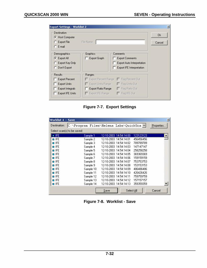
QUICKSCAN 2000 WIN SEVEN - Operating Instructions
7-32
Figure 7-7. Export Settings
Figure 7-8. Worklist - Save

QUICKSCAN 2000 WIN SEVEN - Operating Instructions
7-33
Figure 7-9. Patient Information, Patient Identification
Figure 7-10. Patient Information, Patient Management

QUICKSCAN 2000 WIN SEVEN - Operating Instructions
7-34
Figure 7-11. Patient Search
Figure 7-12. Edit Scan(s), Delimit Bands
Indicator Bar
Cross-hair Cursor

QUICKSCAN 2000 WIN SEVEN - Operating Instructions
7-35
Figure 7-13. Edit Scan(s), Delete Area
Figure 7-14. Edit Scan(s), Baseline Correction

QUICKSCAN 2000 WIN SEVEN - Operating Instructions
7-36
Figure 7-15. Edit Scan(s), Overlay
Figure 7-16. Select Patient Overlay

QUICKSCAN 2000 WIN SEVEN - Operating Instructions
7-37
Figure 7-17. Edit Scan(s), Appearance
Figure 7-18. Edit Scan(s), Input/Output

QUICKSCAN 2000 WIN SEVEN - Operating Instructions
7-38
Figure 7-19. Edit Scan(s), Input/Output, Comments
Figure 7-20. Retrieve Comment/Interpretation
Figure 7-21. Pattern Characteristic

QUICKSCAN 2000 WIN SEVEN - Operating Instructions
7-39
Figure 7-22. Edit Scan(s), Restore
Figure 7-23. IFE Edit Scan(s), Appearance

QUICKSCAN 2000 WIN SEVEN - Operating Instructions
7-40
Figure 7-24. IFE Edit Scan(s), Input/Output
Figure 7-25. Scan Options

QUICKSCAN 2000 WIN SEVEN - Operating Instructions
7-41
Figure 7-26. QC
Figure 7-27. QC History

QUICKSCAN 2000 WIN SEVEN - Operating Instructions
7-42
Figure 7-28. Displays Settings
QUICKSCAN 2000 WIN EIGHT - Test Functions and Quality Control
8-1
Section 8 - Test Functions and Quality Control
8.1. Tests
The instrument automatically performs a self-test any time the power is turned on. Should an error message appear on the display, see section 10.2.
Refer to the appropriate owner’s guide for tests of the monitor and printer.
8.2. Quality Control
On every gel, Helena Laboratories normal control should be run in scan position 1 and/or abnormal control in the last position, and samples in between. The control data should be compared to the ranges printed on the assay sheet provided with the control. Keep a permanent record of the results.
Each laboratory should establish its own reference ranges of expected values for the procedures in use. Refer to the electrophore-sis procedure supplied with the reagents for further information.
It is recommended that each laboratory set up an effective quality control program based on licensing requirements.
8.3. Instrument Performance Check
The QC plate contains a Neutral Density Densitometer Control (NDDC) containing 5 bands of known quantitation, and a 10 Step Optical Density (OD) Step Tablet with an OD Range of .05 to 3.05 in .30 increments. Scan the QC plate at frequent, regular intervals.
The OD Step Tablet checks linearity and analog response of the visible light source and detector.
A list of the quantitative ranges for the NDDC bands should have been entered during QC setup, see section 6.8.1. The quantitation for the five bands is compared to the entered data. Unacceptable results for the 5 bands
are indicated by a plus or minus on the dis-play and report.
1. To QC using the NDDC and OD Step Tablet and/or to manage previous QC results, either select Scan and QC or select the QC icon (the thirteenth icon). The QC window (Figure 7-26) displays.
2. Scan - select to QC using the NDDC/OD Step Tablet. The message “Place the QC Plate in the scanner, click ‘OK’ to continue” displays.
a. Open the scanner lid and place the QC plate in the scanner. The round hole in the QC plate is aligned over the right pin in the scanner and the obround hole over the left pin. Close the lid.
b. Select OK and “Scanning in Progress” displays.
c. The NDDC results are automatically compared to and displayed with the Assayed Value and Expected Range entered in setup.
d. The OD Step Tablet shows proper line-arity when, on the QC printout, a straight line can be drawn which connects the vertical points from the bottom step through, on the Epson Expression scanners model numbers 800, 1600, and 1680, at least 8 steps or, on the Epson Perfection scanners, model num-bers 4870, 4990 and V700, at least 7 steps.
e. If the results are not acceptable:
i. verify that the lid is completely closed and repeat the scan. If the lid is not com-pletely closed, fewer than the applicable number of distinct steps on the OD Step Tablet may be presented.
ii. clean all the glass surfaces in the scanner with a standard glass cleaner and a lint free tissue. Repeat the scan.
iii. optics alignment or instrument ser-vicing may be required. Contact Helena Laboratories for assistance.
3. Print - is available with a QC result dis-played. Select and the Print QC Results

QUICKSCAN 2000 WIN EIGHT - Test Functions and Quality Control
8-2
window displays. As needed, select the appropriate Printer and Number of Copies. Select Print to print the QC results (see Figure 13-7 for an example of a QC printout). Select Cancel to exit without printing. It is recommended that a permanent record of the QC results be kept.
4. History - select to access previous QC results. The availability of previous QC re-sults is dependant upon selections made in setup (section 6.8.1). The QC History window (Figure 7-27) displays. The list of QC results includes the NDDC registration number and the date and time the QC was run. Highlight the desired QC and select from the following:
a. View - select and the QC window dis-plays containing the selected QC.
b. Print - use to print a report containing all previously run QC. The report includes for each previously run QC the NDDC registra-tion number, the date and time of the run, and each of the five NDDC fraction results. The report also includes, for each of the five NDDC fractions, the mean, standard devia-tion, and coefficient of variation, determined from the results of each previously run QC. Select Print, the report prints (Figure 13-8), and the display returns to the QC History window. Select Cancel to return to the win-dow without printing.
c. Delete - use to delete the indicated QC. Select Delete and Alert displays. Select Yes to exit and delete the selected QC or No to exit without deleting QC.
d. Cancel - select to exit the QC History window.
5. To exit the QC window, select the X lo-cated on the top right of the window.

QUICKSCAN 2000 WIN NINE - Performance Specifications
9-1
Section 9 - Performance Specifications
9.1. General Specifications
Tests: Serum Proteins, Urine Proteins, Alkaline Hemoglobins, Alkaline Phosphatase, Choles-terol Profile, CK, LD, IFE, L/S and Lipoproteins
User-Programmable:
Test Parameters: Test, Test Name, Scan Sequence, Gel Stain Type, Immunofixation Electrophoresis, Sam-ple Image Color Intensity, Aperture, Gain Mode, Fraction Detect Sensitivity, Forced Fractions, Smoothing, Unit of Measure, Total Unit of Measure, Decimal Places, (Choles-terol Profile only) Auto Edit and Report Total LDL (Lp(a) + LDL), Auto Interpretation, Com-bine Split Beta, Test Specific Demographics, Channel Width, Scan Positions, Fraction Labels and Ratios, Ratio Labels and Limits, Restricted Band Label, and Reference Ranges.
Display Parameters: Display Scans, Overlay, Edit, Display Per-cent, Display Units, Display Ranges, Display Integrals.
Report Parameters: Report Label, Type of Report, Scans per Report, Paper Size and Orientation, Number of Copies, Print Scan Identifier, Print Patient Information, Print Sample Image, Print Graph, Print Overlay Legend, Overlay Reference, Patient(s), Unedited on Graph, Print IFE Overlay, Print IFE information, Scan Status, Print Results, Print Comments/Interpretations, Print Auto Interpretation, Print User-Defined Text (Headers, Footers, etc.), Print Picture, List and Statistics Reports Print Selected Demographics, Levey-Jennings Reports Select Graph Size
Import /Export Parameters: Communication Parameters including XON-XOFF and ASTM Protocol, and Positive
Sample Identification, Exporter Information, Export Demographics, Export Graph, Export Comments, Export Auto Interpretations, Export IFE Interpretation, Export Percent, Export Units, Export Integrals, Export IFE Units, Export Ratio Range, Export Ranges, Export File Name and Delimiter, and ASTM Fields.
Additional User-Programmable Selections: System Demographic Labels, Comments and Interpretations, E-Mail, QC, Date and Time, Printer, and Password for Setup
Media Types: Agarose and cellulose acetate gels
Maximum Sample Size: 5 x 5 in. (12.7 x 12.7 cm)
Input Power: 120 VAC, 50/60 Hz, 1000 Watts 240 VAC, 50/60 Hz, 1000 Watts
Leakage Current: Less than 5 mA
Dimensions Height x Width x Depth:
Computer, Monitor, and Keyboard: 22 x 18 x 24 in. (56 x 48 x 61 cm)
Scanner: ≤ 8 x 13 x 22 in. (20 x 33 x 56 cm)
Printer: 10 x 14 x 14 in. (26 x 36 x 36 cm)
Total Weight: 104 lbs (47 kg)
Environment: 15° to 27°C (59° to 80.6°F)
Complete specifications for the scanner, monitor and printer can be found in their respective owner’s guide.
9.2. User Programming
Although QuickScan 2000 WIN is factory programmed for each default test, the user may modify instrument operation.

QUICKSCAN 2000 WIN NINE - Performance Specifications
9-2
9.2.1. Programming Test
Unit of Measure: Any units, such as mg/dL, mg/24hrs or U/L.
Ratio Names: Any name for one or two ratios.
Sensitivity: Set sensitivity for optimal results for each test.
Forced Fractions: Choose to have fraction marks “fixed” at the same location as that of the Reference, “floating” (left where they occur if within a window around Reference fraction marks or, if none occur in window, put at the Reference fraction mark position), or forced fractions “off”.
Reference Ranges: Normal ranges (deter-mined from previous runs) assigned for total and each fraction. Can have ranges based on age or sex.
Fraction Names: Up to 10 labeled fractions.
Ratios, Numerator and Denominator: Denote which fractions are in the numerator and denominator of zero, one, or two ratios.
9.2.2. Programming Worklists
Choose how scans are displayed, whether to edit, print, or export data to an external source, and whether or not to save test data automatically for every run.
9.2.3. Programming Report Style
The title, report type, the quantity of scans per report, the paper size and orientation, scan identifier, patient demographics, sample image, graph, overlay legend, scan status, results, comments, auto interpretation, text, pictures, lines, overlays, Levey-Jennings Graph plots, ranges, and number of copies can be selected.
9.2.4. Programming Patient Demographics
Determine what information is to be included in the patient data, and the order in which it will appear. Include up to 10 demographic labels (such as Patient Name, ID Number, Patient Age, Patient Sex, etc.).
9.2.5. Programming Comments
You can write and save comments. Saved comments can be recalled and used with other comments in any patient files.
9.3. Editing
Choose whether or not to edit each scan before storing, printing, or exporting the data. Editing features include: restoring the graph to an unedited form, automatically editing a pattern, automatically setting the scale to bring all peaks onto the graph, overlaying a reference pattern on the graph, aligning the reference with the sample, adding comments, inserting or deleting fraction marks, deleting an area from the pattern, baseline adjust-ment, overlaying an unedited pattern on a edited pattern, overlaying other patient pat-terns, and smoothing a pattern.
9.4. File Retrieval
Determine what information the computer will search for when retrieving files. The selec-tions are similar to Patient Demographics.
9.5. Automatic Data Analysis, Each Scan
Analog curve, fractions, percent, units, inte-grals, one or two ratios, fractions, integrals, high and low indicators when outside normal ranges, and total.

QUICKSCAN 2000 WIN NINE - Performance Specifications
9-3
9.6. Densitometer Specifications
Scanning Parameters: Gain: Automatic or Manual Over range: > 100% of full scale
Optics Mode: Visible Transmittance (white light)
Aperture Sizes (mm): 1 1 x .1 2 2 x .2 3 3 x .3 4 4 x .4 5 6 x .6 6 7 x .7 7 8 x .8 8 2.5 x .25 9 5 x .1 10 5 x .25 11 5 x .5 12 12.18 x 12.18
Scan Length: Variable from 0.01 to 221.5 mm
Zeroing: Automatic
Light Source: Cold Cathode Fluorescent (white light)
Light Detectors: CCD Array
Optical Density Linearity: 0.05 to 3.05 OD - Epson Expression scan-
ner models 800, 1600, 1680 and Perfection model V700
0.05 to 2.3 - Epson Perfection scanner models 4870 and 4990
Operating System: *Microsoft® Windows® 2000 or Windows® XP
*Windows is a registered trademark of Microsoft Inc.

QUICKSCAN 2000 WIN TEN - Maintenance, Troubleshooting, and Warranty
10-1
Section 10 - Maintenance, Troubleshooting, and Warranty
This section describes routine operator main-tenance procedures. For instrument calibration or for maintenance not described in this manual, call Helena Laboratories for assistance.
10.1. Maintenance
WARNING: The QuickScan 2000 WIN is factory lubricated. Do NOT lubricate the instrument.
NOTE: No daily maintenance is required.
10.1.1. General Cleaning
Visually inspect and clean the QuickScan 2000 WIN once a month.
TURN OFF THE POWER AND UNPLUG THE POWER CORDS BEFORE PROCEEDING. Should an instrument be contaminated by blood or blood derivatives, spray any contaminated surface with a com-mercial virucidal and germicidal agent. Observe where the specimens are used inside the instrument and confine cleaning to that area. Wipe up the residue. These mate-rials contain alcohol, which is corrosive to metal surfaces.
Clean outer surfaces and any spills with a damp soft cloth or sponge. Do not use corro-sive or abrasive cleansers. Dry the unit before plugging the power cord in.
10.1.2. Cleaning Scanner Glass
If the glass appears soiled or dusty, clean with a standard glass cleaning solution and a lint free tissue. All glass surfaces in the scanner must be kept clean for best opera-tion.

QUICKSCAN 2000 WIN TEN - Maintenance, Troubleshooting, and Warranty
10-2
10.2. Troubleshooting When using the QuickScan 2000 WIN software, error messages may appear. If corrective action is not obvious, call Helena Laboratories for assistance. For system problems, refer to the following table. If the recommended solutions should fail to solve a problem, call Helena Laboratories for assistance. Also, refer to the component owner’s guide for troubleshooting procedures.
Table 10-1. Troubleshooting
PROBLEM POSSIBLE CAUSE SOLUTION Error message appears Refer to the message Perform actions in message; if recurs,
record the message and call Helena Laboratories for assistance.
Error message Invalid floating point operation appears and program closes
If the Combine Split Beta feature in use, then missing or incorrect Beta label
Label a Fraction/Ratio as "Beta" (sec-tion 6.1.1.2.1 step 7) and rescan gel.
Power cord not plugged in Plug in power cord. Power switch on, no power Bad wall outlet Use another outlet. Brightness turned down Turn up brightness on display, see
monitor owner’s guide. No display (dark screen)
Display power switch off Turn on display power switch. Loose interface or power cable Push cable connections in fully. No presentation on display Defective interface cable Call Helena Laboratories. Did not select Print Select Scan Options, select Print,
select a Printer, a Report, Number of copies, and OK.
Loose interface cable Push cable connections in fully. Paper installed improperly Reinstall paper. Defective interface cable Replace cable. Improper printer setup Refer to printer owner’s guide for
settings.
No printout is produced
Printer off-line but printout requested
Leave printer on-line during operation.
Needs toner/ink Replace toner/ink cartridge. Poor quality printout Other problem Refer to printer owner’s guide. Cable disconnected Firmly insert keyboard or mouse plug
into receptacle on back of computer. Press Alt-Ctrl-Del key to reset program (unsaved data will be lost).
No response to keystrokes or mouse movement
Undetermined cause
Call Helena Laboratories. No fraction marks on patterns Float or Fixed Fraction detection
in use Put Reference as key identifier and/or scan first
Control and/or NDDC out of range
Power surge Call Helena Laboratories.
Invalid floating point error Scan begin/end not in the same order on all rows
Reset scan begin/end lines (section 6.1.1.2.2).
Scan image and scan lines (begin/end and step-over lines) do not line up
Incorrect scanner selected in setup
Select the correct scanner (section 6.9).

QUICKSCAN 2000 WIN TEN - Maintenance, Troubleshooting, and Warranty
10-3
10.3. Warranty
Helena Laboratories warrants its products to meet Helena’s published specifications and to be free from defects in materials and work-manship. Helena’s liability under this contract or otherwise shall be limited to replacement or refund of any amount not to exceed the pur-chase price attributable to the goods as to which such claim is made. These alternatives shall be the buyer’s exclusive remedies. In no case will Helena Laboratories be liable for consequential damages even if Helena has been advised as to the possibility of such damages.
The foregoing warranties are in lieu of all warranties expressed or implied, including, but not limited to, the implied warranties or merchantability and fitness for a particular purpose. In no event will Helena Laboratories be liable for indirect, incidental or consequen-tial damages; the original user's remedies being limited to repair or replacement at the manufacturer's option.
All software and driver disks provided with this instrument must be retained and be accessible in the sleeves provided at the end of this manual for the warranty to be valid.
Warranty Duration
This warranty is provided to the original pur-chaser for six months from date of sale.
Warranty Exclusions
WARNING! Do not use the QuickScan 2000 WIN for any purpose other than that de-scribed in this manual. Modification of the software or the use of the QuickScan 2000 WIN computer to run other programs may affect the operation and reliability of the instrument. Helena Laboratories is not liable for any consequential damages should the customer choose to ignore this warning.
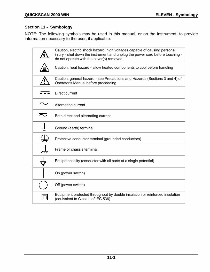
QUICKSCAN 2000 WIN ELEVEN - Symbology
11-1
Section 11 - Symbology
NOTE: The following symbols may be used in this manual, or on the instrument, to provide information necessary to the user, if applicable.
Caution, electric shock hazard, high voltages capable of causing personal injury - shut down the instrument and unplug the power cord before touching - do not operate with the cover(s) removed
Caution, heat hazard - allow heated components to cool before handling
Caution, general hazard - see Precautions and Hazards (Sections 3 and 4) of Operator’s Manual before proceeding
Direct current
Alternating current
Both direct and alternating current
Ground (earth) terminal
Protective conductor terminal (grounded conductors)
Frame or chassis terminal
Equipotentiality (conductor with all parts at a single potential)
On (power switch)
Off (power switch)
Equipment protected throughout by double insulation or reinforced insulation (equivalent to Class II of IEC 536)

QUICKSCAN 2000 WIN TWELVE - Communication Specifications
12-1
Section 12 - Communication Specifications
INTERFACE SPECIFICATIONS:
The QuickScan 2000 WIN import/export interface conforms to the EIA standard RS-332C and is configured as a DTE (Data Terminal Equipment). Only RECEIVE DATA, TRANSMIT DATA and SIGNAL COMMON lines are used. The baud rate is user select-able at 1200, 2400, 4800, 9600 10400, 14400, 19200, or 28800 baud. The number of data bits may be set at 7 or 8 and the number of stop bits may be either 1 or 2. Parity may be set to none, even odd, mark, or space. Protocol options include no protocol, XON-XOFF flow control, or ASTM protocol. The QuickScan 2000 WIN does not order the tests.
MECHANICAL SPECIFICATIONS:
9 pin D-shell connector (male): Pin Description 1 receive line detect 2 receive data* 3 transmit data* 4 data terminal ready 5 signal common* 6 data set ready 7 request to send 8 clear to send 9 ring indicator
*only these lines are used by the QuickScan 2000 WIN software.
COMMUNICATIONS PROTOCOL:
The protocol used by the QuickScan 2000 WIN software is user selectable (see section 6.6). Listed below are the protocol options available.
No Protocol:
Data is transmitted and received as ASCII text with no flow control or error checking/ correction. This option is not recommended unless the Quick Scan 2000 is to be con-nected to a terminal.
XON-XOFF Flow Control:
Data is transmitted and received as ASCII text and XON/XOFF (ASCII codes 17 and 19) hand-shaking is used to control data flow. When importing, the QuickScan 2000 WIN software will transmit an XOFF character when it’s communi-cations buffer becomes three quarters full. Data transmission should stop at this point. The QuickScan 2000 WIN software will process the data in the buffer and when it becomes half empty, an XON character will be transmitted and data transmission can resume. When exporting, the QuickScan 2000 WIN will recognize an XOFF character and stop transmission until an XON character is received. There is no error checking or correction when using this protocol.
ASTM Protocol (E1381-95 and E1394-97):
This protocol provides procedures for link connection and release, delimiting and syn-chronism, sequence control, error detection and error correction. Data is transmitted and received as ASCII text and some restrictions are placed on which characters can be used in the data content. The restricted characters are: <SOH>, <STX>, <ETX>, <EOT>, <ENQ>, <ACK>, <DLE>, <NAK>, <SYN>, <ETB>, <LF>, <DC1>, <DC2>, <DC3>, and <DC4>.
There are three distinct phases in transferring information between the QuickScan 2000 WIN and the computer system. In each phase, one system directs the operation and is responsi-ble for continuity of the communication. The three phases assure the actions of sender and receiver are coordinated. The three phases are Establishment, Transfer, and Terminate.
Establishment Phase
The Establishment phase determines the direc-tion of information flow and prepares the receiver to accept information. The sender notifies the receiver that information is available. The re-ceiver responds that it is prepared to receive before information is transmitted. A system which does not have information to send normally

QUICKSCAN 2000 WIN TWELVE - Communication Specifications
12-2
monitors the data link to detect the establishment phase. It acts as a receiver, waiting for the other system.
The system with information available initiates the establishment phase. After the sender determines the data link is in a neutral state, it transmits the <ENQ> character to the in-tended receiver. Upon receiving the <ENQ>, the receiver prepares to receive information. All other characters are ignored. It replies with the <ACK> character to signify it is ready. With this sequence of events, the establishment phase ends and the transfer phase begins.
A receiver that cannot immediately receive information, replies with the <NAK> character. Upon receiving the <NAK>, the sender must wait at least 10 seconds before transmitting another <ENQ>.
Should both systems simultaneously transmit an <ENQ>, the data link is in contention. The QuickScan 2000 WIN has priority to transmit information when contention occurs. Conten-tion is resolved as follows. Upon receiving a reply of <ENQ> to its transmitted <ENQ>, the computer system must stop trying to transmit, it must prepare to receive. When the next <ENQ> is received, it replies with an <ACK> or <NAK> depending on its readiness to receive.
Transfer Phase
During the transfer phase, the sender trans-mits information to the receiver. The transfer phase continues until all information has been sent.
Information is sent in frames, each frame contains a maximum of 247 characters (in-cluding frame overhead). Records or data that are longer than 240 characters are di-vided between two or more frames. A frame is one of two types, an intermediate frame or an end frame.
Intermediate frames terminate with the characters <ETB>, checksum, <CR> and <LF>. End frames terminate with the characters <ETX>, checksum, <CR> and <LF>. The frame struc-ture is illustrated below:
Intermediate Frame: <STX> FN “data” <ETB> C1 C2 <CR> <LF>
End Frame: <STX> FN “data” <ETX> C1 C2 <CR> <LF>
Where: <STX> - Start of text transmission character
FN - single digit frame number “0” to “7”
“data” - data content
C1 - first character of checksum
“0” - “9” & “A” - “F”
C2 - second character of checksum
“0” - “9” & “A” - “F”
<ETB> - end of transmission block character
<ETX> - end of text transmission character
<CR> - carriage return character
<LF> - line feed character
The frame number is an ASCII digit ranging from “0” to “7”. The frame number begins at “1” with the first frame of the transfer phase. The frame number is incremented by one for each new frame transmitted. After “7”, the frame number rolls over to “0”.
The checksum permits the receiver to detect a defective frame. The checksum is encoded as two characters which are sent after the <ETB> or <ETX> character. The checksum is computed by adding the binary values of the frame characters, keeping the least sig-nificant eight bits of the result. The checksum is transmitted as ASCII hexadecimal.
The checksum is initialized to zero with the <STX> character. The first character used in computing the checksum is the frame num-ber. Each character in the data is added to the checksum (modulo 256). The computa-tion for the checksum does not include
QUICKSCAN 2000 WIN TWELVE - Communication Specifications
12-3
<STX>, the checksum characters, or the trailing <CR> and <LF>.
After the frame is sent, the sender stops transmitting until a reply is received. The receiver replies to each frame. A reply of <ACK> signifies the last frame was received successfully and the receiver is prepared to receive another frame.
A reply of <NAK> signifies the last frame was not received successfully, the receiver is prepared to receive the frame again. Upon receiving the <NAK>, the sender retransmits the last frame with the same frame number. In this way, transmission errors are detected and automatically corrected. A frame is not successfully received if any of the following occur:
1 - any character errors are detected (parity error, framing error, etc.)
2 - the frame checksum doesn’t match the checksum computed on the received frame.
3 - the frame number is not the same as the last accepted frame or one higher (modulo 8).
A frame may be retransmitted up to 6 times. If after 6 tries the frame has still not been successfully transmitted, the sender transmits an <EOT> and regards the data link to be in the neutral state.
A reply of <EOT> signifies the last frame was received successfully, the receiver is ready to receive another frame, but is a request to the sender to stop transmitting. The sender does not have to stop transmitting after receiving the request. If it continues to transmit, there is a possibility of overflowing the receiver’s buffers. If the sender chooses to ignore the <EOT>, the receiver must retransmit the request.
Termination Phase
The termination phase returns the data link to the clear or neutral state. The sender notifies the receiver that all data has been sent.
The sender transmits the <EOT> character and then regards the data link to be in a neutral state. Upon receiving the <EOT>, the receiver also regards the data link to be in the neutral state.
Timeouts
The sender and receiver both use timers to detect loss of coordination between them. The timers provide a method for recovery if the communication line or the other device fails to respond.
During the establishment phase, the sender sets a timer when transmitting the <ENQ>. If a reply of an <ACK>, <NAK> or <ENQ> is not received within 15 seconds, a timeout occurs and the sender regards the link to be in the neutral state.
During the establishment phase, if the com-puter (as receiver) detects contention, it sets a timer. If an <ENQ> is not received within 20 seconds, a timeout occurs and the receiver regards the link to be in the neutral state.
During the transfer phase, the sender sets a timer when transmitting the last character of a frame. If a reply is not received within 15 seconds, a timeout occurs. After a timeout, the sender aborts transmission by proceeding to the termination phase.
During the transfer phase, the receiver sets a timer when first entering the transfer phase or when replying to a frame. If a frame or <EOT> is not received within 30 seconds, a timeout occurs. After a timeout, the receiver discards the last incomplete record or set of data and regards the link to be in the neutral state.
DATA TRANSFER FORMAT
The QuickScan 2000 WIN software in general adheres to the ASTM Standard Specification for Transferring Information Between Clinical Instruments and Computer System. The only exception is the format for transfer of patient information. Because the QuickScan 2000

QUICKSCAN 2000 WIN TWELVE - Communication Specifications
12-4
WIN software allows user designation of the demographic fields, and because the ASTM Standard defines the demographic fields and the order in which they will be transmitted, deviation from the standard can occur. How-ever, the end user can define the QuickScan 2000 WIN demographics to match those defined in the ASTM standard, if strict adher-ence to the standard is required.
General Information
Data is exchanged in records of different types. Each record is introduced by field number 1 identifying the record type, and terminated by a carriage return. There are 7 record types recognized by the QuickScan 2000 WIN: Header Record (H), Patient Re-cord (P), Test Order Record (O), Result Record (R), Comment Record (C), Request Information Record (Q), and the Terminator Record (L).
NOTE: The record ID field shall be case insensitivity.
Records are related to each other in a definite hierarchy. At level zero is the Header record and Terminator record. At level one is the Patient record and the Request-Information record. At level two is the Test Order record. At level three is the Result record. Comment Records do not have an assigned level. A Comment record always relates to the imme-diately preceding Patient, Order, or Result record. Therefore if a Comment record were to follow a patient record (level 1), then the Comment record would be treated as a level 2 record.
A sequence of patient records, order records, or result records at one level is terminated by the appearance of a record type of the same or higher level. Thus, a sequence of results for one patient is terminated by the next patient record.
Each record is composed of fields which are position sensitive and variable in length. Each field is separated by a field delimiter (the
vertical bar, “|”). The position sensitivity requires that when the contents of a field are null, its corresponding field delimiter must be included in the record to ensure that the i’th field can be found by counting (i-1) delimiters. Delimiters are not included for trailing null fields; that is, if the tenth field was the last containing data, the record could terminate after the tenth field (with a carriage return) and therefore would contain only nine delimit-ers.
A system may transmit a null value for a field because (1) it does not know the value, (2) it knows the value is irrelevant to the receiving system, or (3) the value has not changed since the last transmission, or any combina-tion thereof. Because the sending system can use null values to indicate no change, a null value does not overwrite existing data in the receiving system. The transmission of a double quote (ASCII 34) in a field tells the receiving system to replace any existing value with a null value.
Each field may be composed of sub-components. These sub-components are separated by a component delimiter (the caret, “^”). The component delimiter is used to separate data elements of fields of a hier-archical or qualifier nature.
Header Record
The header record must always be the first record in a transmission. When the Quick-Scan 2000 WIN transmits a header record it will have the following format:
H|\^||HELQS2000|hospital ID^QuickScan 2000 WIN ^Version n.nn|address||telephone<CR>
HELQS2000 Password indicating the sending instrument is a Helena QuickScan 2000 WIN
hospital ID - Hospital or laboratory name. This field will be a maximum of 42 characters.
n.nn - QuickScan 2000 WIN software version number

QUICKSCAN 2000 WIN TWELVE - Communication Specifications
12-5
address - Hospital or laboratory ad-dress. This field will be a maximum of 42 characters.
telephone - Hospital or laboratory telephone number. This field will be a maxi-mum of 42 characters.
When the QuickScan 2000 WIN receives a header record it only considers the first two characters to be significant, all other charac-ters up to the carriage return will be ignored. Therefore, the minimum characters the com-puter system needs to transmit for the header record would be:
H|<CR>
Patient Record
When importing data using ASTM, demo-graphic data will automatically be assigned to an ASTM field based on the demographic label. The user may override this automatic assignment in Import / Export setup, see section 6.6.1.
Graph Data Record
The QuickScan 2000 WIN will transmit the graph data in the following format:
M|1|test name|yyyymmddhhmmsshs|ndata^ d1,d2,d3,...dndata|nfractions^f1,f2,f3,...fnfraction|nmspikes^:m11:m12:m21:m31: m32<CR>
test name - Name of test performed.
yyyymmddhhmmsshs - Date and time test was performed. The date is transmitted with the year first, month second, and day last. hs=hundredths of a second.
ndata - The number of data points in the scan. There can be a maximum of 1100 scan data points.
d1,d2,d3,...- Scan data points.
nfractions - Number of fractions for the scan. There can be a maximum of 10 frac-tions.
f1,f2,f3 - Location of fraction boundaries within the scan data.
nmspikes - Number of m-spikes. There can be a maximum of 3 m-spikes.
m11:m12 - Location of the m-spike within the scan data. The first value is the start boundary and the second value is the end boundary.
Order Record
The QuickScan 2000 WIN will transmit an order record immediately preceding any result records for a patient as required in the ASTM specification. The format will be as follows:
O|1|||^^^test name<CR>
test name - Name of the test per-formed.
The QuickScan 2000 WIN currently does not recognize test order records transmitted by the computer system.
Result Record
Each fraction and each ratio of a patient scan will be transmitted as a separate result re-cord. If multiple results for each fraction are required, they will be transmitted in separate records. For example, if the percent and units values of a fraction are required, they will be transmitted in separate records.
A fraction result will be transmitted in the following format:
R|n|^^^test name^fraction name^type|nnnn. nn|unit of measure||nnnn.nnnnnn.nn|f||F||| yyyymmddhhmmsshs<CR>
A ratio result will be transmitted in the follow-ing format:
R|n|^^^test name^ratio name|nnnn.nn|||||F||| yyyymmddhhmmsshs<CR>
n - Sequence number. For the first result record, the value will be 1, for the second, 2, ... etc.

QUICKSCAN 2000 WIN TWELVE - Communication Specifications
12-6
test name - Name of the test per-formed.
fraction name - User defined fraction name.
ratio name - User defined ratio name.
type - Result type, will be one of the following: % (percent), U (units), or I (inte-grals).
nnnn.nn - Fraction or ratio value.
unit of measure - User defined unit of measure. If the result type is “I”, this field will be null.
nnnn.nn-nnnn.nn - User defined refer-ence range.
f - Result abnormal flag. Will be one of the following: L (low), N (normal), or H (high).
yyyymmddhhmmsshs - Date and time the test was performed. The date is transmit-ted with the year first, month second and day last. hs = hundredths of seconds
The QuickScan 2000 WIN does not recognize result records transmitted by the computer system.
Comment Record
The QuickScan 2000 WIN will transmit com-ment records in the following format:
C|1|I|line 1|line 2| ... |line 10<CR>
line - One line of the user entered comments. There can be a maximum of 10 lines, each line a maximum of 76 characters.
The QuickScan 2000 WIN does not recognize comment records transmitted by the computer system.
Request Information Record
The QuickScan 2000 WIN can transmit a request to import patient demographics. This request must be user initiated. The format will be as follows:
Q|1|patient ID<CR>
patient ID - A user entered value which the computer system will recognize as the identifier for a single patient or a group of patients.
The QuickScan 2000 WIN does not recognize request information records transmitted by the computer system.
Terminator Record
The terminator record must be the last record in a transmission. When the QuickScan 2000 WIN transmits a terminator record it will have the following format:
L|1|<CR>
When receiving a terminator record, the QuickScan 2000 WIN only considers the first character significant, all other characters up to the carriage return will be ignored.

QUICKSCAN 2000 WIN THIRTEEN - Reports
13-1
Section 13 - Reports
Figure 13-1. Levey-Jennings Report

QUICKSCAN 2000 WIN THIRTEEN - Reports
13-2
Figure 13-2. List Report

QUICKSCAN 2000 WIN THIRTEEN - Reports
13-3
Figure 13-3. Standard Report

QUICKSCAN 2000 WIN THIRTEEN - Reports
13-4
Figure 13-4. Statistics Report
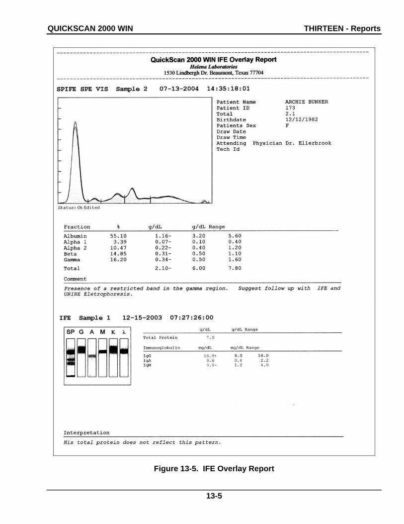
QUICKSCAN 2000 WIN THIRTEEN - Reports
13-5
Figure 13-5. IFE Overlay Report

QUICKSCAN 2000 WIN THIRTEEN - Reports
13-6
Figure 13-6. Two-Scan Standard Report

QUICKSCAN 2000 WIN THIRTEEN - Reports
13-7
Figure 13-7. QC Results

QUICKSCAN 2000 WIN THIRTEEN - Reports
13-8
Figure 13-8. QC History Report

QUICKSCAN 2000 WIN FOURTEEN - Icons
14-1
Section 14 - Icons
1 2 3 4 5 6 7 8 9 10 11 12
13 14 15 16 17 18 19
QUICKSCAN 2000 WIN FOURTEEN - Icons
14-2
1. Open/Close/Select Worklist: select to access and handle the list of currently setup worklists.
2. Scan New Gel: with gel in scanner, select and gel is scanned.
3. Scan Options: use to temporarily alter the scan parameters and positions.
4. Enter Patient Info: select to access the controls needed to enter patient demographic informa-tion.
5. Retrieve Scan(s) from Archive: with the appropriate Retrieve Worklist selected, select to access the controls needed to retrieve saved data.
6. Retrieve Scan(s) from E-Mail: with the appropriate Retrieve Worklist selected, select to access the controls needed to retrieve e-mailed data.
7. Set Display Options: use to temporarily alter the quantity of scans displayed, the numeric data displayed, and/or edit functions.
8. Edit Scan(s): select to access the controls needed to edit the current scan(s).
9. Print Scan(s): select to access the controls needed to print the current scan(s).
10. Export Scan(s): select to access the controls needed to export the current scan(s).
11. Save Scan(s) to Archive: select to access the controls needed to save the current scan(s).
12. Clear Worklist: with the appropri-ate Worklist selected, select and when prompted, answer Yes.
13. QC: select to access the controls needed to perform a quality control test.
14. First: select to view the first scan in the worklist.
15. Previous: select to view the previously viewed scan.
16. Go To: select, select the sample number of the desired scan, and select OK.
17. Next: select to view the next scan.
18. Last: select to view the last scan in the worklist.
19. About: select to view the software version number and the system serial number.
QUICKSCAN 2000 WIN FIFTEEN - Flow Chart
15-1
Section 15 - Flow Chart

QUICKSCAN 2000 WIN FIFTEEN - Flow Chart
15-2

QUICKSCAN 2000 WIN FIFTEEN - Flow Chart
15-3

QUICKSCAN 2000 WIN FIFTEEN - Flow Chart
15-4

QUICKSCAN 2000 WIN FIFTEEN - Flow Chart
15-5

QUICKSCAN 2000 WIN FIFTEEN - Flow Chart
15-6
Adjust colored lines as needed
Green
Red
Blue
Purple

QUICKSCAN 2000 WIN FIFTEEN - Flow Chart
15-7

QUICKSCAN 2000 WIN FIFTEEN - Flow Chart
15-8

QUICKSCAN 2000 WIN FIFTEEN - Flow Chart
15-9
© November, 2012 D6500096K Helena Laboratories, Inc. 11/12
Section 16 - Index
A Abnormal Control, 8-1 About, 7-24 Aperture, 6-3, 7-19 Appearance, 7-15 Archive, 6-27, 7-9
Setup, 6-27 Print, 6-27
Arrow Icons, 7-24 ASTM, 6-25, 12-1, 12-3, 12-5 Auto Edit, 6-2, 6-5, 7-13, 7-14
Settings, 6-5, 7-14 Auto Interpretation, 6-3, 6-16,
6-19, 6-20, 6-23, 7-16, 7-18 Auto Scale, 7-15 Auto Slope Correction, 6-4, 7-
20
B Backup, 6-30 Baseline Correction, 7-14 Baud Rate, 6-24
C Calibration, 8-1 Channel Width, 6-3, 7-19 Channels per Sample, 6-3, 7-
19 Cholesterol, 6-2, 6-5, 6-6, 7-
13, 7-14 Cleaning, 10-1 Clear Worklist, 7-9 Comment / Interpretation, 6-
11, 6-16, 6-19, 6-20, 6-22, 6-23, 7-16, 7-18 Export, 6-11 Print, 6-23 Setup, 6-22 Print, 6-23
Communication Specifications, 12-1
Computer, 5-2
D Data Bits, 6-24 Date and Time, 6-29, 7-3
Setup, 6-29 Decimal Places, 6-2 Delete, 6-12, 7-5, 7-14, 7-22
Area, 7-14 Fraction Delimiter, 7-13
Delimit Bands, 7-13 Fractions, Restricted
Bands and Auto Edit, 7-13
Demographics, 6-3, 6-11, 6-13, 6-14, 6-25 Setup, 6-13 Print, 6-14
Diagnostics, 6-24 Display Options, 7-22 Display Settings, 6-9, 7-4, 7-
20, 7-22
E Edit, 6-5, 6-9, 6-13, 7-4, 7-10,
7-12, 7-14, 7-20, 7-22 Patients, 7-10, 7-11, 7-16 Scans, 7-12, 7-15, 7-16, 7-
18 IFE, 7-17
Electrophoresis Sample Handler, 6-24, 7-12 Positive Sample
Identification, 6-24, 7-4 E-mail, 6-25
Retrieve, 7-5 Exit, 7-10 Export, 6-11, 6-24, 6-25, 6-
26, 7-5, 7-7, 7-17, 7-18, 7-20 Scans, 7-7 Settings, 6-11, 7-5, 7-7, 7-
20 Export File, 6-25
F File, 7-2, 7-5, 7-7 Force Lp(a) Fraction, 6-5, 7-
14 Forced Fractions, 6-4, 7-20
Fixed, 6-4, 7-20 Float, 6-4, 7-20
Fraction Detection Sensitivity, 6-4, 7-19
Fractions / Ratios, 6-3
G Gain Mode, 6-3, 7-19
Auto, 6-3, 7-19 Manual, 6-4, 7-19
Gel Stain Type, 6-2 Graph, 6-17
Export, 6-11 Levey-Jennings, 6-10, 6-
15, 6-21
H Help and About, 7-24 Host Computer, 6-24
I Immunofixation
Electrophoresis (IFE), 6-2, 6-3, 6-7
Import, 6-24, 6-25, 6-26, 7-12, 12-5
Import / Export, 6-24, 6-26, 12-5 Setup, 6-24
Installation, 5-1 Inventory, 5-1
K Keyboard, 5-3
L Laboratory Information
Systems (LIS), 6-24, 6-25, 7-12
Levey-Jennings, 6-10, 6-15, 6-21
Line, 6-21
M Maintenance, 10-1 Monitor, 5-3 Mouse, 5-3
© November, 2012 D6500096K Helena Laboratories, Inc. 11/12
M-Spike, 6-3
N Neutral Density Densitometer
Control (NDDC), 6-27, 6-28, 7-21, 7-22, 8-1, 8-2
O Optical Density Step Tablet
(OD Step Tablet), 6-27, 6-28, 7-21, 8-1
Overlay, 6-9, 6-10, 6-16, 6-17, 6-18, 7-14, 7-15, 7-22
P Parity, 6-24, 12-1 Password, 6-1, 6-26, 6-30 Patient Information, 6-16, 6-
17, 7-10, 7-11, 7-16, 7-18 Percent, 6-11, 6-23 Picture, 6-21 Port Number, 6-24, 6-26 Positive Sample Identification,
6-24, 7-4 Powering Up Instrument, 5-3 Preview, 6-9, 7-22 Print, 6-10, 7-5, 7-6, 7-17, 7-
18, 7-20, 7-22, 8-1, 8-2 Print Scans, 7-6 Print Settings, 6-10, 7-5, 7-6,
7-20 Printer, 5-2, 6-29, 7-6
Setup, 6-29 Protocol, 6-24, 12-1
Q Quality Control (QC), 6-27, 6-
28, 7-21, 7-22, 8-1, 8-2 Setup, 6-27 Print, 6-28
R Range Type, 6-6 Ratio, 6-3 Reference, 6-9, 7-14, 7-22 Reference Ranges, 6-6 Report Total LDL (Lp(a) +
LDL), 6-3 Reports, 6-14
Setup, 6-14 Print, 6-22 Types, 6-15 Levey-Jennings, 6-10, 6-
15 List, 6-15, 6-21 Standard, 6-15 Statistics, 6-15, 6-21
Restore, 6-30, 6-31, 7-17 Restricted Band, 6-3, 7-13 Results, 6-2, 6-9, 6-11, 6-12,
6-16, 6-18, 6-20, 7-22, 7-23, 7-28, 8-1
Retrieve from Archive, 7-2 E-mail, 7-5 File, 7-2
Rows per Gel, 6-2
S Sample Application per Row,
6-2 Sample Image, 6-16, 6-17 Save, 6-12, 7-5, 7-9, 7-17, 7-
18, 7-20 Scan
New Gel, 7-18 Previous Gel, 7-19
Scan Identifier, 6-16, 6-18 Scan Options, 7-19 Scan Position, 6-5, 6-6, 6-27,
7-20, 7-21 Scan Status, 6-16, 6-19 Scanner, 5-3, 6-28
Setup, 6-28, 6-29 Print, 6-29
Sex / Age Requirements, 6-6 Smooth, 6-4, 6-5, 7-15, 7-20 Stop Bits, 6-24 System Requirements, 5-2
T Table, 6-21 Tests
Setup, 6-1 Altering, 6-2 Default, 6-1
Text, 6-21 Total Unit of Measure, 6-2 Troubleshooting, 10-2
U Undo, 7-17 Unit of Measure, 6-2 Units, 6-11, 6-23 Unpacking and Inspection, 5-
1 User Setup, 6-1, 6-22, 6-23,
6-26, 6-29, 6-30, 6-31
V Verification of Functionality,
5-5 View, 7-22, 7-23, 8-2
W Warranty, 10-3 Windows, 7-23, 7-24 Worklist
Clear, 7-9 Close, 7-2 Open, 7-2 Select, 7-2 Setup, 6-7, 6-13 Print, 6-12
Z Zoom, 7-15

© November, 2012 D6500096K Helena Laboratories, Inc. 11/12
QuickScan 2000 WIN Version 2
Catalog Numbers 1660, 1661, 1662, 1663, 1673, 1678, and 1679
Software Version 2.02
Operator's Manual
For additional information, call Helena Laboratories at 800-231-5663, toll free.
Helena Laboratories P.O. Box 752
Beaumont, Texas 77704-0752