QUICKII: SOFTWARE FOR FAB · port to the PC. 1.3.4 Communication with FAB 1.3.4.1 Local FAB...
57
QuickII 1 QUICKII: SOFTWARE FOR FAB QUICK II is programming software for FAB machine to implement program- ming and simulation on PC. It can not only implement the preparation of control program (function diagram) for FAB, but also simulate the operations of the edited program and display clearly the running results in order to determine the accuracy of the edited program. Besides, QUICK II can execute short-distance and remote communication of FAB, and write edited program into EEPROM of FAB machine.
Transcript of QUICKII: SOFTWARE FOR FAB · port to the PC. 1.3.4 Communication with FAB 1.3.4.1 Local FAB...

QuickII
1
QUICKII: SOFTWARE FOR FAB
QUICK II is programming software for FAB machine to implement program-
ming and simulation on PC. It can not only implement the preparation of control
program (function diagram) for FAB, but also simulate the operations of the edited
program and display clearly the running results in order to determine the accuracy
of the edited program. Besides, QUICK II can execute short-distance and remote
communication of FAB, and write edited program into EEPROM of FAB machine.
FAB Intelligent Controller
2
RESUMERESUME
Chapter I Introduction to QuickII
3
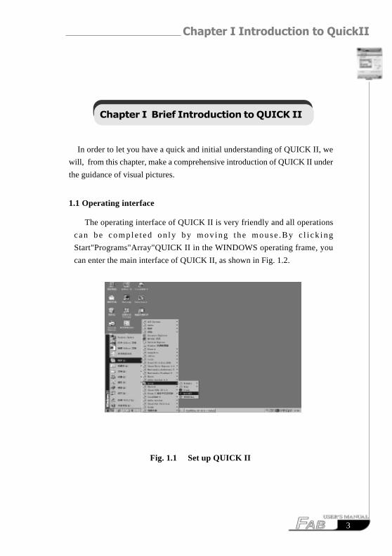
Chapter I Brief Introduction to QUICK II
In order to let you have a quick and initial understanding of QUICK II, we
will, from this chapter, make a comprehensive introduction of QUICK II under
the guidance of visual pictures.
1.1 Operating interface
The operating interface of QUICK II is very friendly and all operations
can be comple t ed on ly by mov ing t he mouse .By c l i ck ing
Start"Programs"Array"QUICK II in the WINDOWS operating frame, you
can enter the main interface of QUICK II, as shown in Fig. 1.2.
Fig. 1.1 Set up QUICK II
FAB Intelligent Controller
4
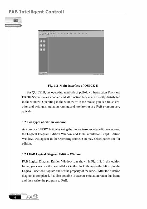
Fig. 1.2 Main Interface of QUICK II
For QUICK II, the operating methods of pull-down Instruction Tools and
EXPRESS button are adopted and all function blocks are directly distributed
in the window. Operating in the window with the mouse you can finish cre-
ation and writing, simulation running and monitoring of a FAB program very
quickly.
1.2 Two types of edition windows
As you click “NEW” button by using the mouse, two cascaded edition windows,
the Logical Diagram Edition Window and Field simulation Graph Edition
Window, will appear in the Operating frame. You may select either one for
edition.
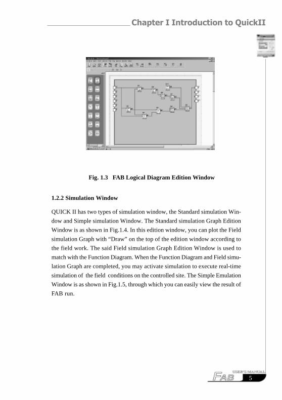
1.2.1 FAB Logical Diagram Edition Window
FAB Logical Diagram Edition Window is as shown in Fig. 1.3. In this edition
frame, you can click the desired block in the block library on the left to plot the
Logical Function Diagram and set the property of the block. After the function
diagram is completed, it is also possible to execute emulation run in this frame
and then write the program to FAB.
Chapter I Introduction to QuickII
5
Fig. 1.3 FAB Logical Diagram Edition Window
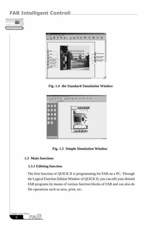
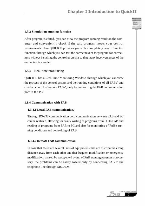
1.2.2 Simulation Window
QUICK II has two types of simulation window, the Standard simulation Win-
dow and Simple simulation Window. The Standard simulation Graph Edition
Window is as shown in Fig.1.4. In this edition window, you can plot the Field
simulation Graph with “Draw” on the top of the edition window according to
the field work. The said Field simulation Graph Edition Window is used to
match with the Function Diagram. When the Function Diagram and Field simu-
lation Graph are completed, you may activate simulation to execute real-time
simulation of the field conditions on the controlled site. The Simple Emulation
Window is as shown in Fig.1.5, through which you can easily view the result of
FAB run.
FAB Intelligent Controller
6
Fig. 1.4 the Standard Simulation Window
Fig. 1.5 Simple Simulation Window
1.3 Main functions
1.3.1 Editting function
The first function of QUICK II is programming for FAB on a PC. Through
the Logical Function Edition Window of QUICK II, you can edit your desired
FAB programs by means of various function blocks of FAB and can also do
file operations such as save, print, etc.
Chapter I Introduction to QuickII
7
1.3.2 Simulation running function
After program is edited, you can view the program running result on the com-
puter and conveniently check if the said program meets your control
requirements. Here QUICK II provides you with a completely new offline test
function, through which you can test the correctness of theprogram for correct-
ness without installing the controller on site so that many inconveniences of the
online test is avoided.
1.3.3 Real-time monitoring
QUICK II has a Real-Time Monitoring Window, through which you can view
the process of the control system and the running conditions of all FABs’ and
conduct control of remote FABs’, only by connecting the FAB communication
port to the PC.
1.3.4 Communication with FAB
1.3.4.1 Local FAB communication.
Through RS-232 communication port, communication between FAB and PC
can be realized, allowing for easily writing of programs from PC to FAB and
reading of programs from FAB to PC and also for monitoring of FAB’s run-
ning conditions and controlling of FAB.
1.3.4.2 Remote FAB communication
In case that there are several sets of equipments that are distributed a long
distance away from each other and that frequent modification or emergency
modification, caused by unexpected event, of FAB running program is neces-
sary, the problems can be easily solved only by connecting FAB to the
telephone line through MODEM.
FAB Intelligent Controller
8
RESUMERESUME
Chapter II Instrallation and Uninstallation
9
Chapter II Installation and uninstallation
2.1 Installation of QUICK II
Installation of QUICK II is very simple. A Prompt frame will appear automati-
cally and you will finish the installation smoothly on the computer under its
guidance. The main steps are as follows:
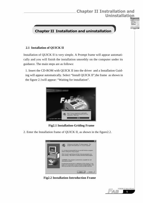
1. Insert the CD-ROM with QUICK II into the driver and a Installation Guid-
ing will appear automatically. Select “Install QUICK II”,the frame as shown in
the figure 2.1will appear: “Waiting for installation”.
Fig2.1 Installation-Griding Frame
2. Enter the Installation frame of QUICK II, as shown in the figure2.2.
Fig2.2 Installation-Introduction Frame
FAB Intelligent Controller
1 0
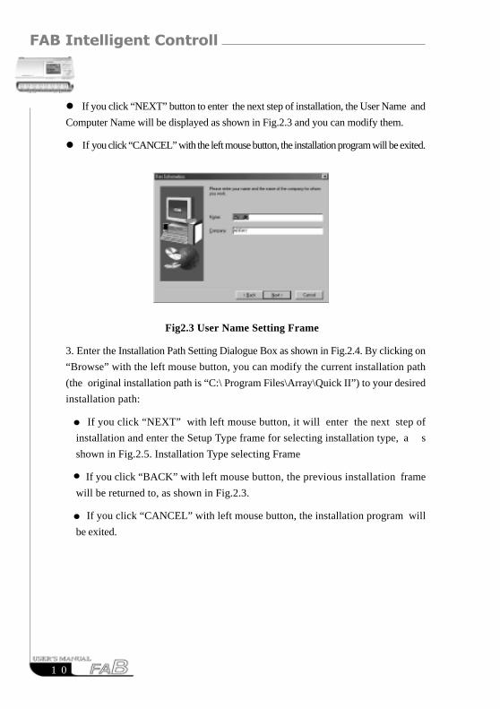
� If you click “NEXT” button to enter the next step of installation, the User Name and
Computer Name will be displayed as shown in Fig.2.3 and you can modify them.
� If you click “CANCEL” with the left mouse button, the installation program will be exited.
Fig2.3 User Name Setting Frame
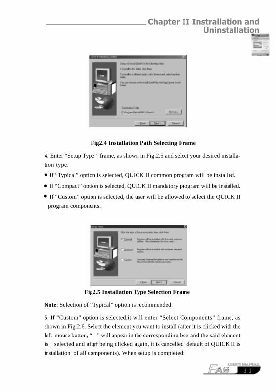
3. Enter the Installation Path Setting Dialogue Box as shown in Fig.2.4. By clicking on
“Browse” with the left mouse button, you can modify the current installation path
(the original installation path is “C:\ Program Files\Array\Quick II”) to your desired
installation path:
If you click “NEXT” with left mouse button, it will enter the next step of
installation and enter the Setup Type frame for selecting installation type, a s
shown in Fig.2.5. Installation Type selecting Frame
If you click “BACK” with left mouse button, the previous installation frame
will be returned to, as shown in Fig.2.3.
If you click “CANCEL” with left mouse button, the installation program will
be exited.
Chapter II Instrallation and Uninstallation
1 1
Fig2.4 Installation Path Selecting Frame
4. Enter “Setup Type” frame, as shown in Fig.2.5 and select your desired installa-
tion type.
If “Typical” option is selected, QUICK II common program will be installed.
If “Compact” option is selected, QUICK II mandatory program will be installed.
If “Custom” option is selected, the user will be allowed to select the QUICK II
program components.
Fig2.5 Installation Type Selection Frame
Note: Selection of “Typical” option is recommended.
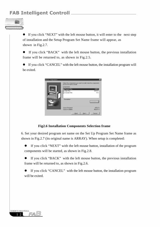
5. If “Custom” option is selected,it will enter “Select Components” frame, as
shown in Fig.2.6. Select the element you want to install (after it is clicked with the
left mouse button, “ ” will appear in the corresponding box and the said element
is selected and after being clicked again, it is cancelled; default of QUICK II is
installation of all components). When setup is completed:
FAB Intelligent Controller
1 2
Fig2.6 Installation Components Selection frame
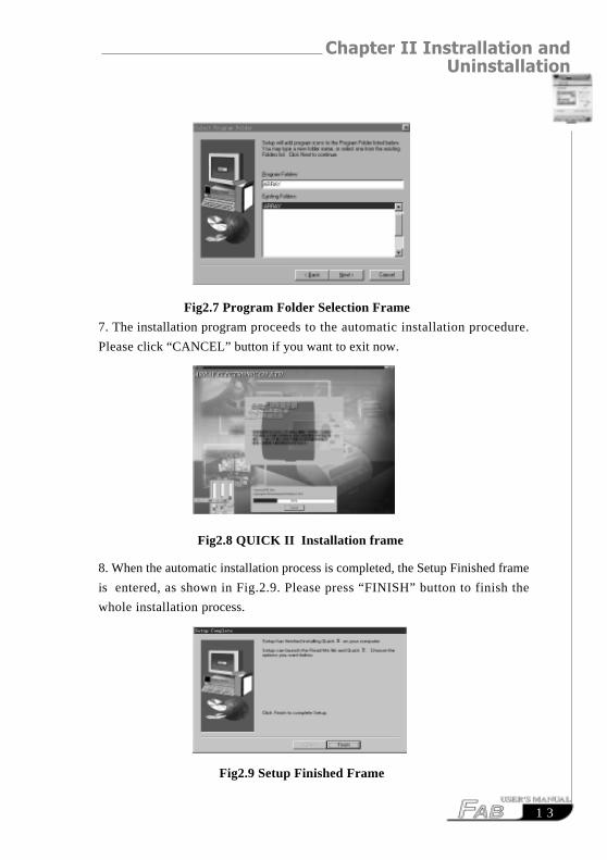
6. Set your desired program set name on the Set Up Program Set Name frame as
shown in Fig.2.7 (its original name is ARRAY). When setup is completed:
� If you click “NEXT” with the left mouse button, installation of the program
components will be started, as shown in Fig.2.8.
� If you click “BACK” with the left mouse button, the previous installation
frame will be returned to, as shown in Fig.2.6.
� If you click “CANCEL” with the left mouse button, the installation program
will be exited.
� If you click “NEXT” with the left mouse button, it will enter to the next step
of installation and the Setup Program Set Name frame will appear, as
shown in Fig.2.7.
� If you click “BACK” with the left mouse button, the previous installation
frame will be returned to, as shown in Fig.2.5.
� If you click “CANCEL” with the left mouse button, the installation program will
be exited.
Chapter II Instrallation and Uninstallation
1 3
Fig2.7 Program Folder Selection Frame
7. The installation program proceeds to the automatic installation procedure.
Please click “CANCEL” button if you want to exit now.
Fig2.8 QUICK II Installation frame
8. When the automatic installation process is completed, the Setup Finished frame
is entered, as shown in Fig.2.9. Please press “FINISH” button to finish the
whole installation process.
Fig2.9 Setup Finished Frame
FAB Intelligent Controller
1 4
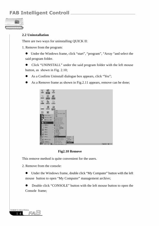
2.2 Uninstallation
There are two ways for uninstalling QUICK II:
1. Remove from the program:
� Under the Windows frame, click “start”, “program”, “Array “and select the
said program folder.
� Click “UNINSTALL” under the said program folder with the left mouse
button, as shown in Fig. 2.10;
� As a Confirm Uninstall dialogue box appears, click “Yes”;
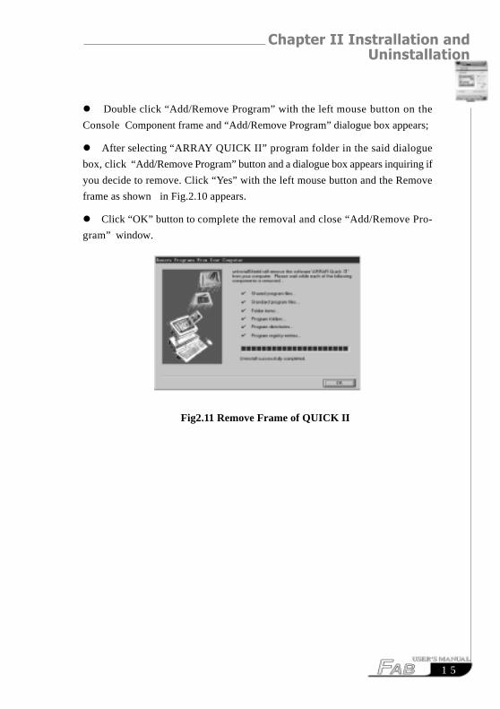
� As a Remove frame as shown in Fig.2.11 appears, remove can be done;
Fig2.10 Remove
This remove method is quite convenient for the users.
2. Remove from the console:
� Under the Windows frame, double click “My Computer” button with the left
mouse button to open “My Computer” management archive;
� Double click “CONSOLE” button with the left mouse button to open the
Console frame;
Chapter II Instrallation and Uninstallation
1 5
� Double click “Add/Remove Program” with the left mouse button on the
Console Component frame and “Add/Remove Program” dialogue box appears;
� After selecting “ARRAY QUICK II” program folder in the said dialogue
box, click “Add/Remove Program” button and a dialogue box appears inquiring if
you decide to remove. Click “Yes” with the left mouse button and the Remove
frame as shown in Fig.2.10 appears.
� Click “OK” button to complete the removal and close “Add/Remove Pro-
gram” window.
Fig2.11 Remove Frame of QUICK II

FAB Intelligent Controller
1 6
RESUMERESUME
1 7
Chapter III Operation Instructions and Block Library
Chapter III Operation Instructions and Block Library
3.1 Function Instructions
When QUICK II is used to edit FAB programs, some basic operations including files
management, opening and closing of Tool Bar and Status Bar and Help information
are completed by means of pulled-down instructions under File, Controller, Com-
munication, View, Option and Help. The Instruction Function list of QUICK II is
characterized by its flexibility and variability. It can be changed according to the
current operation for convenience of your various operations.
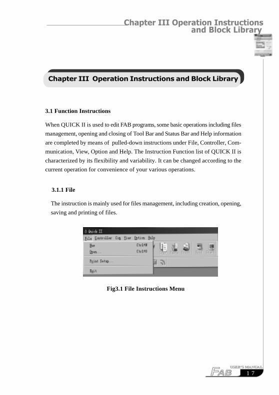
3.1.1 File
The instruction is mainly used for files management, including creation, opening,
saving and printing of files.
Fig3.1 File Instructions Menu
FAB Intelligent Controller
1 8
3.1.2 Controller
The instruction is mainly used for reading programs from FAB. Start QUICK II.
after its operating interface being entered, click Controller Function List with the
left mouse button. The following is displayed:
Fig3.2 Controller Instruction Menu
3.1.3 Communication
The instruction is mainly used for online setup of FAB with the upper computer.
Fig3.3 Communication Instruction Menu
Instruction Name Function
New Open a new file
Open Open a old file
Close Close the current active Window
Save Save a file
Save As Save current file to a new path & a new file
Print Print a file
Print Preview Preview the file printing result
Setup Print Setup printing format
Exit Exit QUICK II
1 9
Chapter III Operation Instructions and Block Library
� Configure communication: selection of communication mode and setup of
communication port.
� Turn off communication: when it is not necessary for FAB to communicate
with the upper computer, click this option to disconnect and stop communication.
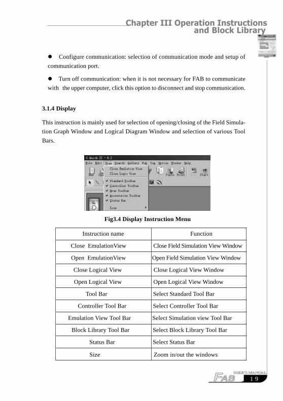
3.1.4 Display
This instruction is mainly used for selection of opening/closing of the Field Simula-
tion Graph Window and Logical Diagram Window and selection of various Tool
Bars.
Fig3.4 Display Instruction Menu
Instruction name Function
Close EmulationView Close Field Simulation View Window
Open EmulationView Open Field Simulation View Window
Close Logical View Close Logical View Window
Open Logical View Open Logical View Window
Tool Bar Select Standard Tool Bar
Controller Tool Bar Select Controller Tool Bar
Emulation View Tool Bar Select Simulation view Tool Bar
Block Library Tool Bar Select Block Library Tool Bar
Status Bar Select Status Bar
Size Zoom in/out the windows
FAB Intelligent Controller
2 0
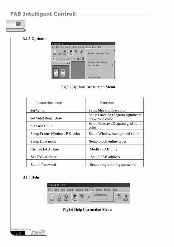
3.1.5 Options:
Fig3.5 Options Instruction Menu
Instruction name Function
Set Wine Setup block online color
Set Valid Regin Base
Set Grid Color
Setup Frame Windows BK-color Setup Window background color
Setup Line mode Setup block online types
Change FAB Time Modify FAB time
Set FAB Address Setup FAB address
Setup Password Setup programming password
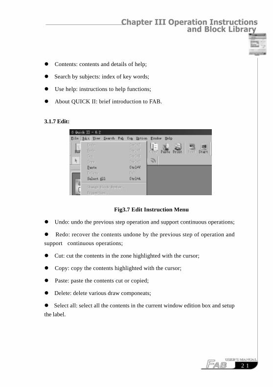
3.1.6 Help:
Fig3.6 Help Instruction Menu
Setup Function Diagram significantdraw zone colorSetup Function Diagram grid pointcolor
2 1
Chapter III Operation Instructions and Block Library
� Contents: contents and details of help;
� Search by subjects: index of key words;
� Use help: instructions to help functions;
� About QUICK II: brief introduction to FAB.
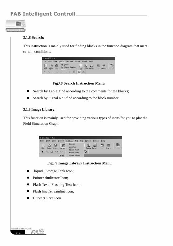
3.1.7 Edit:
Fig3.7 Edit Instruction Menu
� Undo: undo the previous step operation and support continuous operations;
� Redo: recover the contents undone by the previous step of operation and
support continuous operations;
� Cut: cut the contents in the zone highlighted with the cursor;
� Copy: copy the contents highlighted with the cursor;
� Paste: paste the contents cut or copied;
� Delete: delete various draw componeats;
� Select all: select all the contents in the current window edition box and setup
the label.
FAB Intelligent Controller
2 2
3.1.8 Search:
This instruction is mainly used for finding blocks in the function diagram that meet
certain conditions.
Fig3.8 Search Instruction Menu
� Search by Lable: find according to the comments for the blocks;
� Search by Signal No.: find according to the block number.
3.1.9 Image Library:
This function is mainly used for providing various types of icons for you to plot the
Field Simulation Graph.
Fig3.9 Image Library Instruction Menu
� liquid : Storage Tank Icon;
� Pointer :Indicator Icon;
� Flash Text : Flashing Text Icon;
� Flash line :Streamline Icon;
� Curve :Curve Icon.
2 3
Chapter III Operation Instructions and Block Library
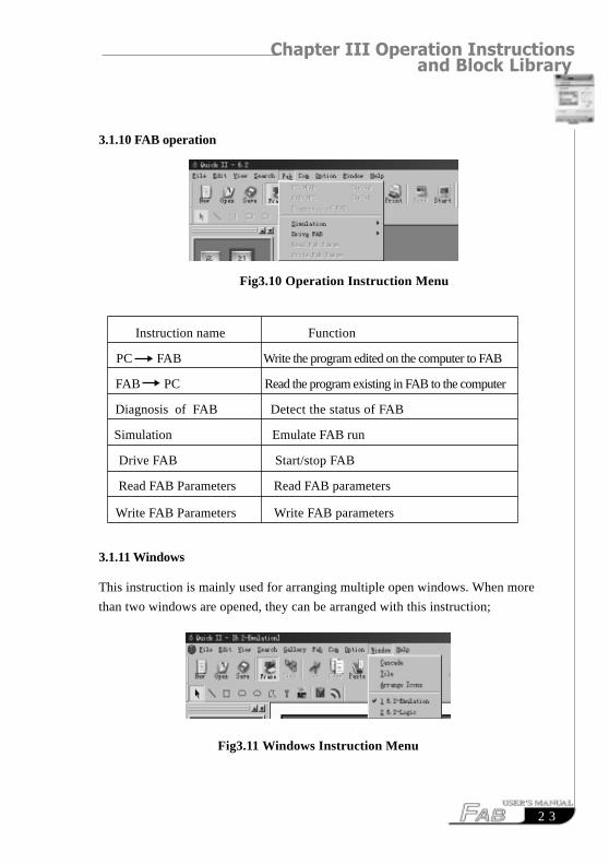
3.1.10 FAB operation
Fig3.10 Operation Instruction Menu
Instruction name Function
PC FAB Write the program edited on the computer to FAB
FAB PC Read the program existing in FAB to the computer
Diagnosis of FAB Detect the status of FAB
Simulation Emulate FAB run
Drive FAB Start/stop FAB
Read FAB Parameters Read FAB parameters
Write FAB Parameters Write FAB parameters
3.1.11 Windows
This instruction is mainly used for arranging multiple open windows. When more
than two windows are opened, they can be arranged with this instruction;
Fig3.11 Windows Instruction Menu
FAB Intelligent Controller
2 4
� Cascade: cascade sub-lists;
� Tile: display sub-lists in parallel
� Arrange: arrange the sub-lists in the form of icons.
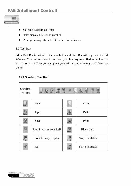
3.2 Tool Bar
After Tool Bar is activated, the icon buttons of Tool Bar will appear in the Edit
Window. You can use these icons directly without trying to find in the Function
List. Tool Bar will let you complete your editing and drawing work faster and
better.
3.2.1 Standard Tool Bar
New Copy
Open Paste
Save Print
Read Program from FAB Block Link
Block Library Display Stop Simulation
Cut Start Simulation
Standard
Tool Bar
2 5
Chapter III Operation Instructions and Block Library
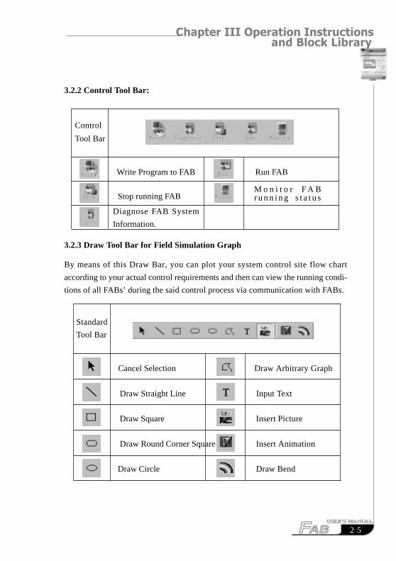
3.2.2 Control Tool Bar:
Write Program to FAB Run FAB
Stop running FAB
3.2.3 Draw Tool Bar for Field Simulation Graph
By means of this Draw Bar, you can plot your system control site flow chart
according to your actual control requirements and then can view the running condi-
tions of all FABs’ during the said control process via communication with FABs.
Cancel Selection Draw Arbitrary Graph
Draw Straight Line Input Text
Draw Square Insert Picture
Draw Round Corner Square Insert Animation
Draw Circle Draw Bend
Diagnose FAB System
Information.
Control
Tool Bar
M o n i t o r F A Br u n n i n g s t a t u s
Standard
Tool Bar
FAB Intelligent Controller
2 6
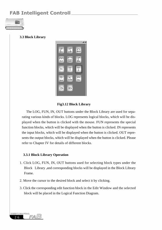
3.3 Block Library
Fig3.12 Block Library
The LOG, FUN, IN, OUT buttons under the Block Library are used for sepa-
rating various kinds of blocks. LOG represents logical blocks, which will be dis-
played when the button is clicked with the mouse. FUN represents the special
function blocks, which will be displayed when the button is clicked. IN represents
the input blocks, which will be displayed when the button is clicked. OUT repre-
sents the output blocks, which will be displayed when the button is clicked. Please
refer to Chapter IV for details of different blocks.
3.3.1 Block Library Operation
1. Click LOG, FUN, IN, OUT buttons used for selecting block types under the
Block Library ,and corresponding blocks will be displayed in the Block Library
Frame.
2. Move the cursor to the desired block and select it by clicking.
3. Click the corresponding edit function block in the Edit Window and the selected
block will be placed in the Logical Function Diagram.
2 7
Chapter III Operation Instructions and Block Library
3.3.2 Block classification
The blocks are classified into four types: Logical Block, Function Block, Input
Block and Output Block. The Input and Output blocks are only used to lively
represent the input and output ends of FAB, without any actual functions. The
key parts are the Logical Block and Function Block, the combination of which
realizes Several types of FAB control.
3.3.3 Setup of block property
It is necessary to setup the properties of the blocks in plotting of logical diagrams.
The block properties are divided into General property and Special property.
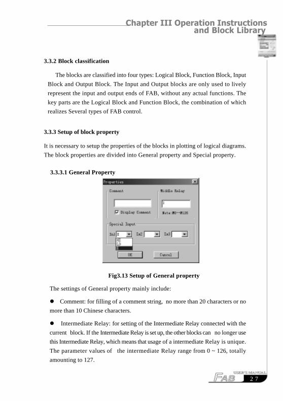
3.3.3.1 General Property
Fig3.13 Setup of General property
The settings of General property mainly include:
� Comment: for filling of a comment string, no more than 20 characters or no
more than 10 Chinese characters.
� Intermediate Relay: for setting of the Intermediate Relay connected with the
current block. If the Intermediate Relay is set up, the other blocks can no longer use
this Intermediate Relay, which means that usage of a intermediate Relay is unique.
The parameter values of the intermediate Relay range from 0 ~ 126, totally
amounting to 127.
FAB Intelligent Controller
2 8
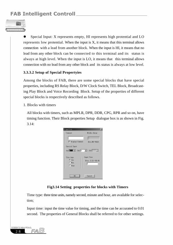
� Special Input: X represents empty, HI represents high protential and LO
represents low protential. When the input is X, it means that this terminal allows
connection with a lead from another block. When the input is HI, it means that no
lead from any other block can be connected to this terminal and its status is
always at high level. When the input is LO, it means that this terminal allows
connection with no lead from any other block and its status is always at low level.
3.3.3.2 Setup of Special Propertyies
Among the blocks of FAB, there are some special blocks that have special
properties, including RS Relay Block, D/W Clock Switch, TEL Block, Broadcast-
ing Play Block and Voice Recording Block. Setup of the properties of different
special blocks is respectively described as follows.
1. Blocks with timers
All blocks with timers, such as MPLR, DPR, DDR, CPG, RPR and so on, have
timing function. Their Block properties Setup dialogue box is as shown in Fig.
3.14:
Fig3.14 Setting properties for blocks with Timers
Time type: three time units, namely second, minute and hour, are available for selec-
tion;
Input time: input the time value for timing, and the time can be accurated to 0.01
second. The properties of General Blocks shall be referred to for other settings.
2 9
Chapter III Operation Instructions and Block Library
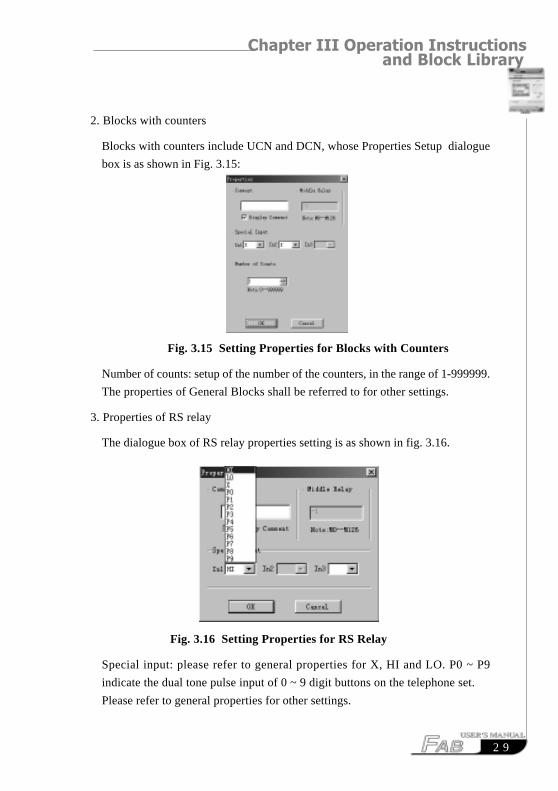
2. Blocks with counters
Blocks with counters include UCN and DCN, whose Properties Setup dialogue
box is as shown in Fig. 3.15:
Fig. 3.15 Setting Properties for Blocks with Counters
Number of counts: setup of the number of the counters, in the range of 1-999999.
The properties of General Blocks shall be referred to for other settings.
3. Properties of RS relay
The dialogue box of RS relay properties setting is as shown in fig. 3.16.
Fig. 3.16 Setting Properties for RS Relay
Special input: please refer to general properties for X, HI and LO. P0 ~ P9
indicate the dual tone pulse input of 0 ~ 9 digit buttons on the telephone set.
Please refer to general properties for other settings.

FAB Intelligent Controller
3 0
4. Property of TEL Block
The dialogue box is as shown in Fig. 3.17:
Phone code: telephone number used for dial-up is keyed in here and the “*, #”
functions of the telephone are not supported. The length of the telephone
number shall be not beyond 25 digits. Please refer to general properties for other
settings.
Fig3.17 Setting TEL Block Property
5. Properties of CW Clock Switch Block:
The Setup dialogue box is as shown in Fig.3.18:
Clock setup: In this setting, the status of output can be regularly changed. Two
options as “Date style” and “Week style” are provided to meet the require-
ments of users with different habits.
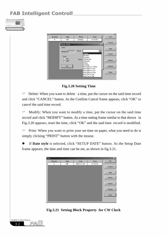
Fig3.18 Setting CW Clock Switch Block Properties
3 1
Chapter III Operation Instructions and Block Library
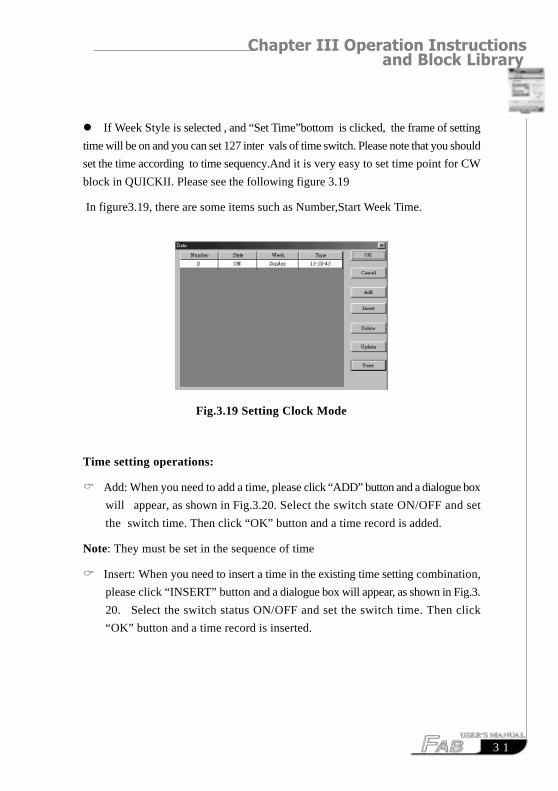
� If Week Style is selected , and “Set Time”bottom is clicked, the frame of setting
time will be on and you can set 127 inter vals of time switch. Please note that you should
set the time according to time sequency.And it is very easy to set time point for CW
block in QUICKII. Please see the following figure 3.19
In figure3.19, there are some items such as Number,Start Week Time.
Fig.3.19 Setting Clock Mode
Time setting operations:
� Add: When you need to add a time, please click “ADD” button and a dialogue box
will appear, as shown in Fig.3.20. Select the switch state ON/OFF and set
the switch time. Then click “OK” button and a time record is added.
Note: They must be set in the sequence of time
� Insert: When you need to insert a time in the existing time setting combination,
please click “INSERT” button and a dialogue box will appear, as shown in Fig.3.
20. Select the switch status ON/OFF and set the switch time. Then click
“OK” button and a time record is inserted.
FAB Intelligent Controller
3 2
Fig.3.20 Setting Time
� Delete: When you want to delete a time, put the cursor on the said time record
and click “CANCEL” button. As the Confirm Cancel frame appears, click “OK” to
cancel the said time record.
� Modify: When you want to modify a time, put the cursor on the said time
record and click “MODIFY” button. As a time setting frame similar to that shown in
Fig.3.20 appears, reset the time, click “OK” and the said time record is modified.
� Print: When you want to print your set time on paper, what you need to do is
simply clicking “PRINT” button with the mouse.
� If Date style is selected, click “SETUP DATE” button. As the Setup Date
frame appears, the date and time can be set, as shown in fig.3.21.
Fig.3.21 Setting Block Property for CW Clock
3 3
Chapter III Operation Instructions and Block Library
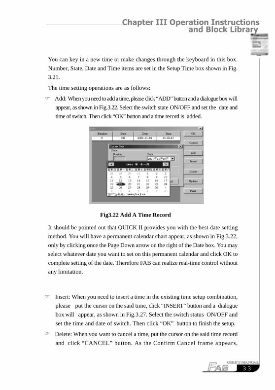
You can key in a new time or make changes through the keyboard in this box.
Number, State, Date and Time items are set in the Setup Time box shown in Fig.
3.21.
The time setting operations are as follows:
� Add: When you need to add a time, please click “ADD” button and a dialogue box will
appear, as shown in Fig.3.22. Select the switch state ON/OFF and set the date and
time of switch. Then click “OK” button and a time record is added.
Fig3.22 Add A Time Record
It should be pointed out that QUICK II provides you with the best date setting
method. You will have a permanent calendar chart appear, as shown in Fig.3.22,
only by clicking once the Page Down arrow on the right of the Date box. You may
select whatever date you want to set on this permanent calendar and click OK to
complete setting of the date. Therefore FAB can realize real-time control without
any limitation.
� Insert: When you need to insert a time in the existing time setup combination,
please put the cursor on the said time, click “INSERT” button and a dialogue
box will appear, as shown in Fig.3.27. Select the switch status ON/OFF and
set the time and date of switch. Then click “OK” button to finish the setup.
� Delete: When you want to cancel a time, put the cursor on the said time record
and click “CANCEL” button. As the Confirm Cancel frame appears,
FAB Intelligent Controller
3 4
click “OK” to delete the time record.
� Modify: When you want to modify a time, put the cursor on the said time
record and click “MODIFY” button. As a time setting frame similar to
what shown in
Fig.3.26 appears, reset the state, date and time, click “OK” and the said
time record is modified.
� Print: When you want to print your set time on paper, what you need to do
is simply clicking “PRINT” button with the mouse.
Note:
(1) The time is arranged in an order earlier to later and the time sequence shall be
considered for adding or modifying any time record, for example: AM9:00,
AM11:00, PM3:00, PM6:00, etc;
(2) In case of multiple records, the said block will be divided into multiple
blocks when it is written to FAB and you can view the number of blocks used by
the current program in the State Bar of the Function Graph Edit Window;
(3) If the first time is set ON and the second is set OFF , the two times share
one common block; if two consecutive time are both set to ON or OFF, each of
them should occupy a separate block.
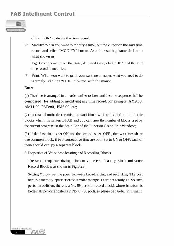
6. Properties of Voice broadcasting and Recording Blocks
The Setup Properties dialogue box of Voice Brondcasting Block and Voice
Record Block is as shown in Fig.3.23.
Setting Output: set the ports for voice broadcasting and recording. The port
here is a memory space oriented at voice storage. There are totally 1 ~ 98 such
ports. In addition, there is a No. 99 port (for record block), whose function is
to clear all the voice contents in No. 0 ~ 98 ports, so please be careful in using it.
3 5
Chapter III Operation Instructions and Block Library
Fig.3.23 Setup the Properties of
Voice broadcasting and Recording Blocks
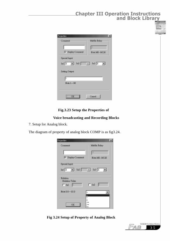
7. Setup for Analog block.
The diagram of property of analog block COMP is as fig3.24.
Fig 3.24 Setup of Property of Analog Block
FAB Intelligent Controller
3 6
The explanation of option listed in Fig 3.24 is as follows:
(1) comment: Users can add explanation letters in this bar.
(2) Special input: HI,LO,X,LM.
If X has been selected, this said port can be connected to Input port.
If LM has been selected, it means that this said port can be set to a fixed digital
value. Please refer the (3) items to know how to set the value.
(3) Relation Value
The range of LM is 0.0~10.0.
(4)Relation
It provides “<,>,=,>=,<=,=” 6 options. And this comparison block is for the
comparison between input 1 and input 3.
For example.
When “ <” has been selected,
if input 1<input 3,then Q=1. if input 1>input3 , then Q=0.
RESUMERESUME

Chapter IV Basic operations
3 7
Chapter IV Basic operations
This chapter will intuoduce how to use QUICK II to edit the Logical Function
Diagram Program and plot the Field Environment Control Diagram, how to use
it to emulate running the edited program and how to make PC communicate with
FAB so as to complete writing of the program to FAB.
If you want to make a Function Diagram Program, you should first open a
new empty file and put all the blocks required for satisfying the control require-
ments into the Edit Box. Then set the properties of different function blocks and
link them up with lines according to their logical control relations, thus complet-
ing a Logical Function Diagram. Moreover, in order to help the user know if the
edited function diagram can completely achieve the expected control effects,
QUICK II provides the user with an extremely direct emulation function. You can
run the emulation function either directly on the Function Diagram or on the Field
Emulation Graph. In both cases, the detailed result of FAB running in accordance
with the program can be observed,In the following ,we will introduce QUICKII
with an example
Example: using FAB to compose a multi-function switch for a staircase light-
ing system Control requirements:
1. Lighting is turned on upon pressing of the switch and automatically
turned off after one minute;
2. Lighting flashes 5 seconds before automatically turning off;
3. Lighting is turned on upon twice pressing of the switch and maintained
constantly on;
4. Lighting is turned off when the switch is pressed for
2 seconds and more;
5. Lighting is automatically turned on at PM18:30 and off at AM6:30
every day.
FAB Intelligent Controller
3 8
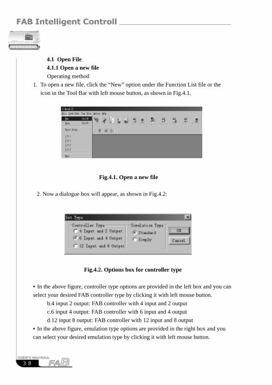
4.1 Open File4.1.1 Open a new file
Operating method
1. To open a new file, click the “New” option under the Function List file or the
icon in the Tool Bar with left mouse button, as shown in Fig.4.1.
Fig.4.1. Open a new file
2. Now a dialogue box will appear, as shown in Fig.4.2:
Fig.4.2. Options box for controller type
• In the above figure, controller type options are provided in the left box and you can
select your desired FAB controller type by clicking it with left mouse button.
b.4 input 2 output: FAB controller with 4 input and 2 output
c.6 input 4 output: FAB controller with 6 input and 4 output
d.12 input 8 output: FAB controller with 12 input and 8 output
• In the above figure, emulation type options are provided in the right box and you
can select your desired emulation type by clicking it with left mouse button.
Chapter IV Basic operations
3 9
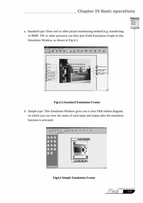
a. Standard type: Draw tool or other picture transferring method (e.g. transferring
of BMP, TIF or other pictures) can beto plot Field Emulation Graph in this
Emulation Window, as shown in Fig.4.3.
Fig.4.3.Standard Emulation Frame
b. Simple type: This Emulation Window gives you a clear FAB outline diagram,
on which you can view the status of each input and output after the emulation
function is activated.
Fig4.4 Simple Emulation Frame
FAB Intelligent Controller
4 0
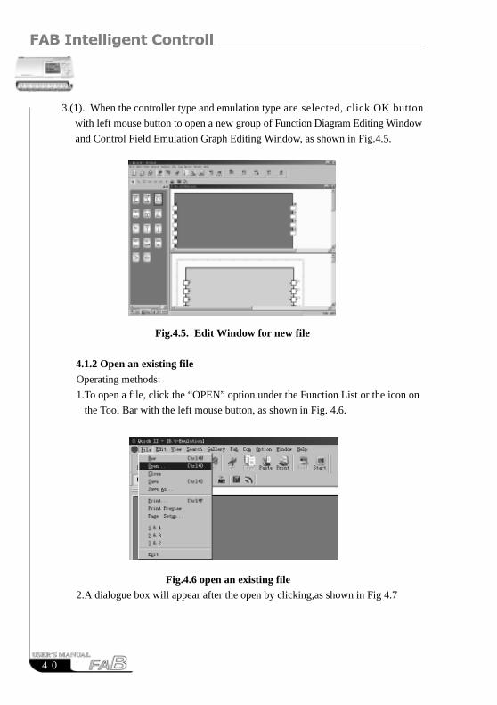
Fig.4.5. Edit Window for new file
4.1.2 Open an existing file
Operating methods:
1.To open a file, click the “OPEN” option under the Function List or the icon on
the Tool Bar with the left mouse button, as shown in Fig. 4.6.
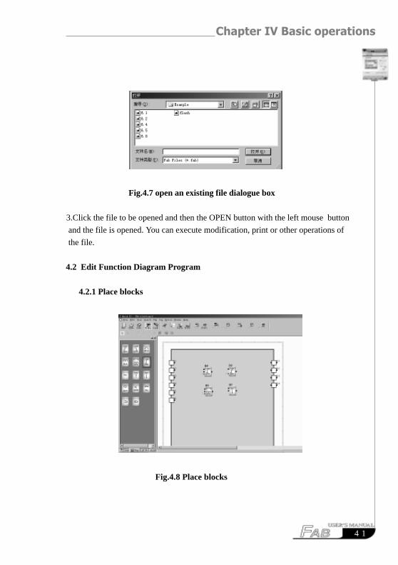
Fig.4.6 open an existing file2.A dialogue box will appear after the open by clicking,as shown in Fig 4.7
3.(1). When the controller type and emulation type are selected, click OK button
with left mouse button to open a new group of Function Diagram Editing Window
and Control Field Emulation Graph Editing Window, as shown in Fig.4.5.
Chapter IV Basic operations
4 1
Fig.4.7 open an existing file dialogue box
3.Click the file to be opened and then the OPEN button with the left mouse button
and the file is opened. You can execute modification, print or other operations of
the file.
4.2 Edit Function Diagram Program
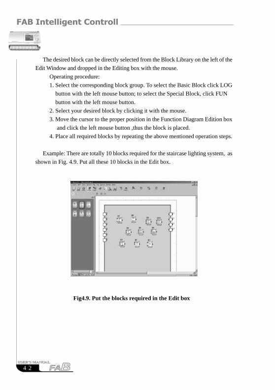
4.2.1 Place blocks
Fig.4.8 Place blocks
FAB Intelligent Controller
4 2
The desired block can be directly selected from the Block Library on the left of the
Edit Window and dropped in the Editing box with the mouse.
Operating procedure:
1. Select the corresponding block group. To select the Basic Block click LOG
button with the left mouse button; to select the Special Block, click FUN
button with the left mouse button.
2. Select your desired block by clicking it with the mouse.
3. Move the cursor to the proper position in the Function Diagram Edition box
and click the left mouse button ,thus the block is placed.
4. Place all required blocks by repeating the above mentioned operation steps.
Example: There are totally 10 blocks required for the staircase lighting system, as
shown in Fig. 4.9. Put all these 10 blocks in the Edit box.
Fig4.9. Put the blocks required in the Edit box
Chapter IV Basic operations
4 3
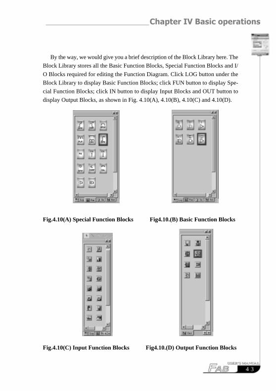
By the way, we would give you a brief description of the Block Library here. The
Block Library stores all the Basic Function Blocks, Special Function Blocks and I/
O Blocks required for editing the Function Diagram. Click LOG button under the
Block Library to display Basic Function Blocks; click FUN button to display Spe-
cial Function Blocks; click IN button to display Input Blocks and OUT button to
display Output Blocks, as shown in Fig. 4.10(A), 4.10(B), 4.10(C) and 4.10(D).
Fig.4.10(A) Special Function Blocks Fig4.10.(B) Basic Function Blocks
Fig.4.10(C) Input Function Blocks Fig4.10.(D) Output Function Blocks
FAB Intelligent Controller
4 4
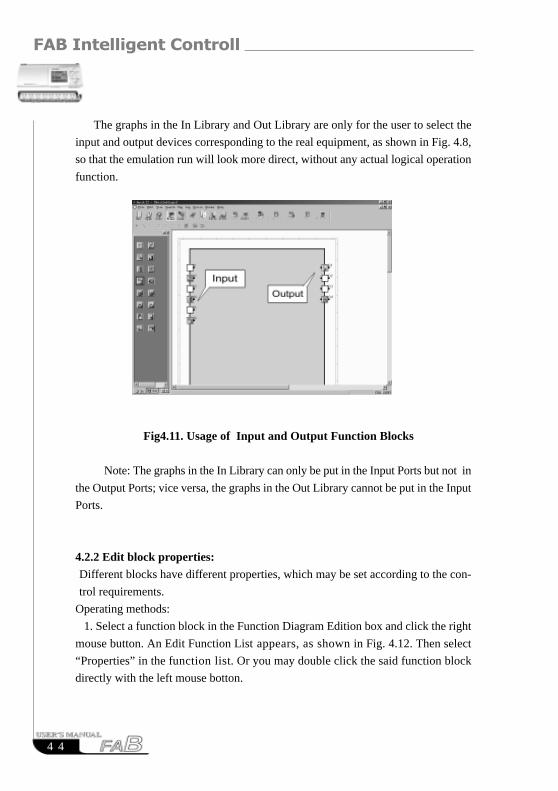
The graphs in the In Library and Out Library are only for the user to select the
input and output devices corresponding to the real equipment, as shown in Fig. 4.8,
so that the emulation run will look more direct, without any actual logical operation
function.
Fig4.11. Usage of Input and Output Function Blocks
Note: The graphs in the In Library can only be put in the Input Ports but not in
the Output Ports; vice versa, the graphs in the Out Library cannot be put in the Input
Ports.
4.2.2 Edit block properties:Different blocks have different properties, which may be set according to the con-
trol requirements.
Operating methods:
1. Select a function block in the Function Diagram Edition box and click the right
mouse button. An Edit Function List appears, as shown in Fig. 4.12. Then select
“Properties” in the function list. Or you may double click the said function block
directly with the left mouse botton.
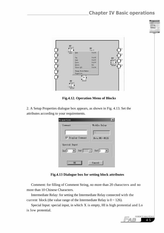
Chapter IV Basic operations
4 5
Fig.4.12. Operation Menu of Blocks
2. A Setup Properties dialogue box appears, as shown in Fig. 4.13. Set the
attributes according to your requirements.
Fig.4.13 Dialogue box for setting block attributes
Comment: for filling of Comment String, no more than 20 characters and no
more than 10 Chinese Characters.
Intermediate Relay: for setting the Intermediate Relay connected with the
current block (the value range of the Intermediate Relay is 0 ~ 126).
Special Input: special input, in which X is empty, HI is high protential and Lo
is low protential.
FAB Intelligent Controller
4 6
3. Click OK button with the mouse to complete the setup.
4. Set the properties of all blocks by repeating the above operating steps.
Note: Different blocks have different properties setup, especially the Special
Function blocks. Please refer to Chapter III,Section3.4 for details.
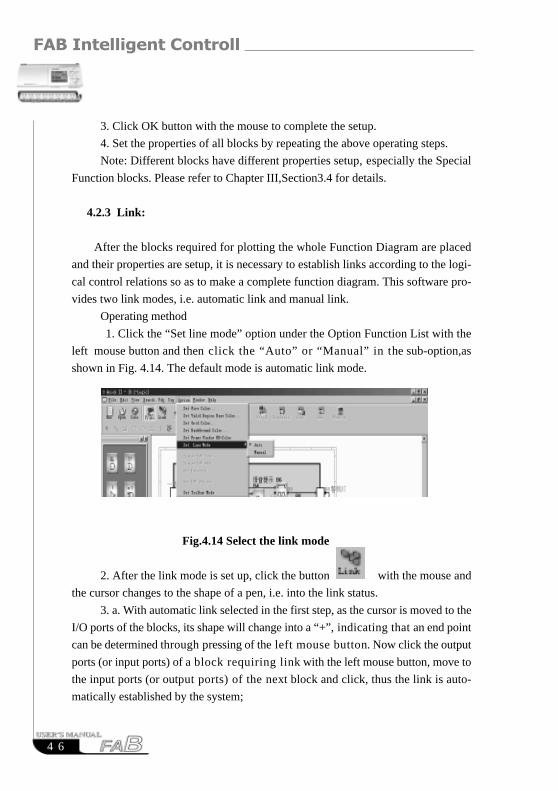
4.2.3 Link:
After the blocks required for plotting the whole Function Diagram are placed
and their properties are setup, it is necessary to establish links according to the logi-
cal control relations so as to make a complete function diagram. This software pro-
vides two link modes, i.e. automatic link and manual link.
Operating method
1. Click the “Set line mode” option under the Option Function List with the
left mouse button and then click the “Auto” or “Manual” in the sub-option,as
shown in Fig. 4.14. The default mode is automatic link mode.
Fig.4.14 Select the link mode
2. After the link mode is set up, click the button with the mouse and
the cursor changes to the shape of a pen, i.e. into the link status.
3. a. With automatic link selected in the first step, as the cursor is moved to the
I/O ports of the blocks, its shape will change into a “+”, indicating that an end point
can be determined through pressing of the left mouse button. Now click the output
ports (or input ports) of a block requiring link with the left mouse button, move to
the input ports (or output ports) of the next block and click, thus the link is auto-
matically established by the system;
Chapter IV Basic operations
4 7
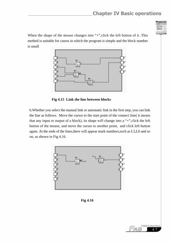
Fig 4.15 Link the line between blocks
b.Whether you select the manual link or automatic link in the first step, you can link
the line as follows. Move the cursor to the start point of the connect line( it means
that any input or output of a block), its shape will change into a “+”,click the left
button of the mouse, and move the cursor to another point, and click left button
again. At the ends of the lines,there will appear mark numbers,such as L5,L6 and so
on, as shown in Fig 4.16.
Fig 4.16
When the shape of the mouse changes into “+”,click the left botton of it .This
methed is suitable for casess in which the program is simple and the block number
is small
FAB Intelligent Controller
4 8
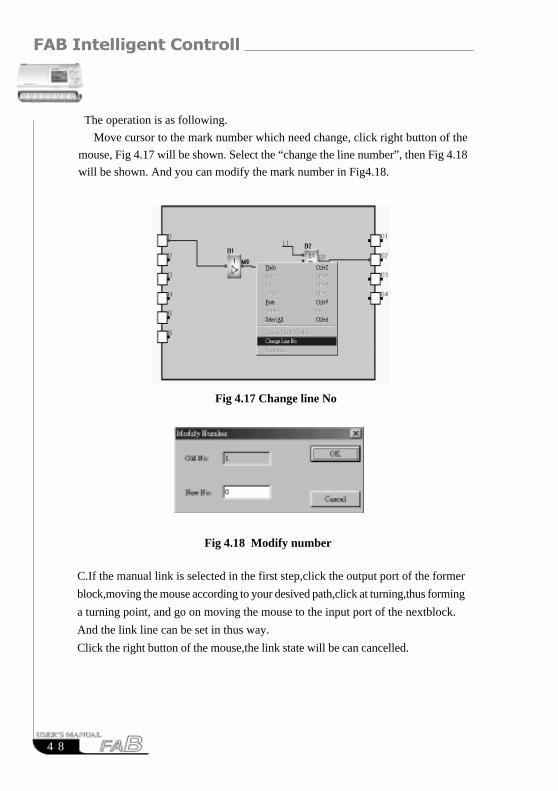
The operation is as following.
Move cursor to the mark number which need change, click right button of the
mouse, Fig 4.17 will be shown. Select the “change the line number”, then Fig 4.18
will be shown. And you can modify the mark number in Fig4.18.
C.If the manual link is selected in the first step,click the output port of the former
block,moving the mouse according to your desived path,click at turning,thus forming
a turning point, and go on moving the mouse to the input port of the nextblock.
And the link line can be set in thus way.
Click the right button of the mouse,the link state will be can cancelled.
Fig 4.17 Change line No
Fig 4.18 Modify number
Chapter IV Basic operations
4 9
4.2.4 Move the link or block: In case that there are a lot of links and blocks in your Function Diagram the
diagram may be difficult to read due to so many crisscrossing lines, you can move
some of the links or blocks to make the diagram tidy and beautiful.
Operating method:
1. Click the link or block to be moved with the mouse to turn it red;
2. Put the cursor on the link or block to be moved and drag it to the proper
position;
3. Click the left mouse button to complete moving.
4. Move all the links and blocks that need to be moved with the above method to
make the whole function diagram tidy and beautiful.
4.2.5 Delete block or linkWhen you want to delete some unnecessary blocks or wrong links, the
operation methods are as follows:
1. Select the link or block to be deleted with the mouse;
2. Press Delete key on the keyboard, or click the right mouse button and select
the “Delete” option, thus the link or block is deleted.
4.2.6 Simulation operationQUICK II has the Emulation Run Function in addition to edition of
function diagram. When programming is completed, the Emulation Run
Function may be activated for checking if the program meets your control
requirements. The operating method is as follows:
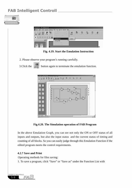
1. To activate emulation, Click “Emulation” option under Instruction FAB
Operation Menu and then “Start” with the left mouse button, as shown in
Fig. 4.19, or directly click the icon in the Tool Bar. Now you can see the
result of program running through the input and output status in the frame,
as shown in Fig. 4.20.
FAB Intelligent Controller
5 0
Fig.4.20. The Simulation operation of FAB Program
In the above Emulation Graph, you can see not only the ON or OFF status of all
inputs and outputs, but also the input status and the current status of timing and
counting of all blocks. So you can easily judge through this Emulation Function if the
edited program meets the control requirements.
4.2.7 Save and Print
Operating methods for files saving:
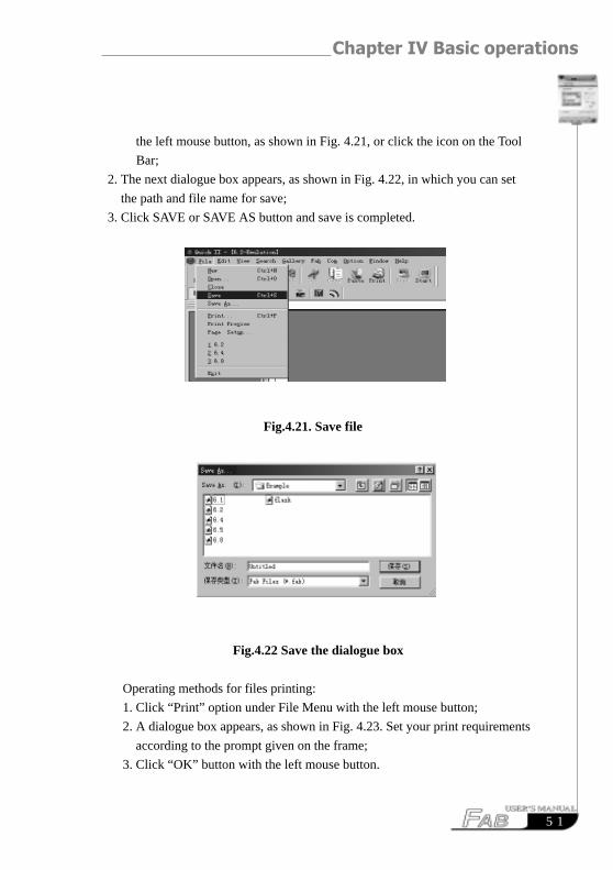
1. To save a program, click “Save” or “Save as” under the Function List with
Fig. 4.19. Start the Emulation Instruction
2. Please observe your program’s running carefully.
3.Click the button again to terminate the emulation function.
Chapter IV Basic operations
5 1
Fig.4.22 Save the dialogue box
Operating methods for files printing:
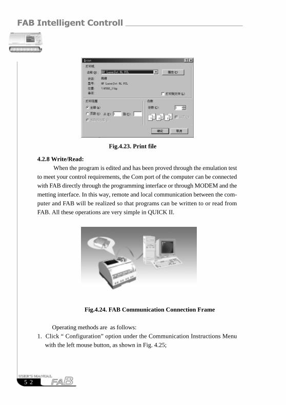
1. Click “Print” option under File Menu with the left mouse button;
2. A dialogue box appears, as shown in Fig. 4.23. Set your print requirements
according to the prompt given on the frame;
3. Click “OK” button with the left mouse button.
the left mouse button, as shown in Fig. 4.21, or click the icon on the Tool
Bar;
2. The next dialogue box appears, as shown in Fig. 4.22, in which you can set
the path and file name for save;
3. Click SAVE or SAVE AS button and save is completed.
Fig.4.21. Save file
FAB Intelligent Controller
5 2
Fig.4.23. Print file
4.2.8 Write/Read:
When the program is edited and has been proved through the emulation test
to meet your control requirements, the Com port of the computer can be connected
with FAB directly through the programming interface or through MODEM and the
metting interface. In this way, remote and local communication between the com-
puter and FAB will be realized so that programs can be written to or read from
FAB. All these operations are very simple in QUICK II.
Fig.4.24. FAB Communication Connection Frame
Operating methods are as follows:
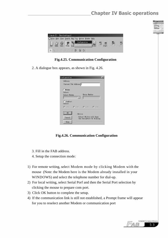
1. Click “ Configuration” option under the Communication Instructions Menu
with the left mouse button, as shown in Fig. 4.25;
Chapter IV Basic operations
5 3
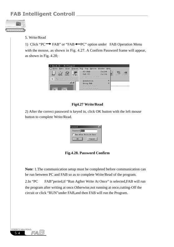
2. A dialogue box appears, as shown in Fig. 4.26.
Fig.4.26. Communication Configuration
3. Fill in the FAB address.
4. Setup the connection mode:
1) For remote writing, select Modem mode by clicking Modem with the
mouse (Note: the Modem here is the Modem already installed in your
WINDOWS) and select the telephone number for dial-up.
2) For local writing, select Serial Porf and then the Serial Port selection by
clicking the mouse to prepare com port.
3) Click OK button to complete the setup.
4) If the communication link is still not established, a Prompt frame will appear
for you to reselect another Modem or communication port
Fig.4.25. Communication Configuration
FAB Intelligent Controller
5 4
5. Write/Read
1) Click “PC
FAB” or “FAB
PC” option under FAB Operation Menu
with the mouse, as shown in Fig. 4.27. A Confirm Password frame will appear,
as shown in Fig. 4.28;
Fig4.27 Write/Read
Fig.4.28. Password Confirm
Note: 1.The communication setup must be completed before communication can
be run between PC and FAB so as to complete Write/Read of the program.
2.In “PC
FAB”peried,if “Run Agfter Write At Once” is selected,FAB will run
the program after writing at once.Otherwise,not running at once,cutting-Off the
circuit or click “RUN”under FAB,and then FAB will run the Program.
2) After the correct password is keyed in, click OK button with the left mouse
button to complete Write/Read.
Chapter IV Basic operations
5 5
4.3 Plot Field Emulation Graph
When the Standard Emulation Edit Window of QUICK II is in activated status,
you can directly plot in the Edit box using the icons in the Draw Bar or insert BMP
or animation Picture using BMP or Animation in the Tool Bar. This makes QUICK
II more convenient for you and you can easily plot an ideal Field Emulation Graph
with it. If the Draw Bar is not displayed, it can be selected from the Instructions
Function List.
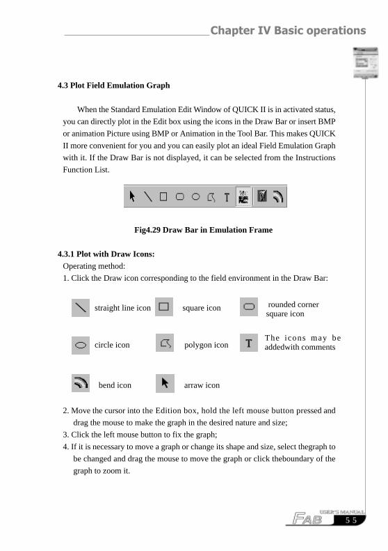
Fig4.29 Draw Bar in Emulation Frame
4.3.1 Plot with Draw Icons:Operating method:
1. Click the Draw icon corresponding to the field environment in the Draw Bar:
2. Move the cursor into the Edition box, hold the left mouse button pressed and
drag the mouse to make the graph in the desired nature and size;
3. Click the left mouse button to fix the graph;
4. If it is necessary to move a graph or change its shape and size, select thegraph to
be changed and drag the mouse to move the graph or click theboundary of the
graph to zoom it.
straight line icon square icon
circle icon polygon icon
bend icon arraw icon
rounded cornersquare icon
The icons may beaddedwith comments
FAB Intelligent Controller
5 6
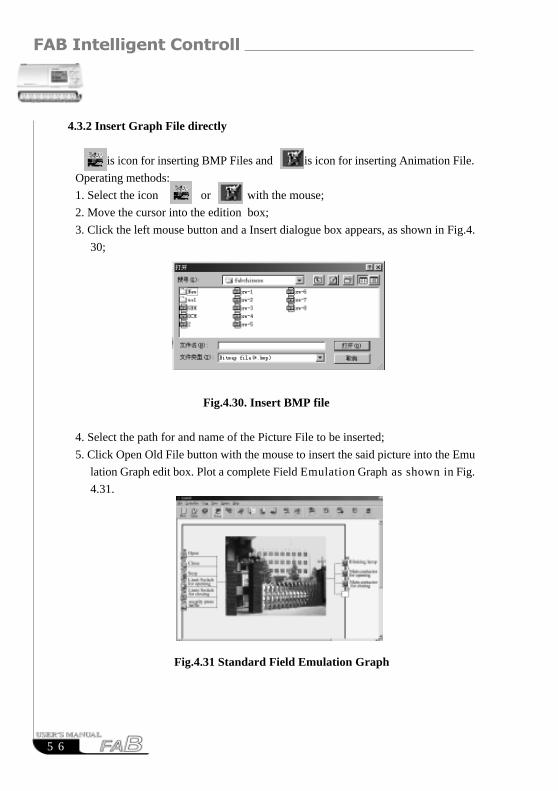
4.3.2 Insert Graph File directly
is icon for inserting BMP Files and is icon for inserting Animation File.
Operating methods:
1. Select the icon or with the mouse;
2. Move the cursor into the edition box;
3. Click the left mouse button and a Insert dialogue box appears, as shown in Fig.4.
30;
Fig.4.30. Insert BMP file
4. Select the path for and name of the Picture File to be inserted;
5. Click Open Old File button with the mouse to insert the said picture into the Emu
lation Graph edit box. Plot a complete Field Emulation Graph as shown in Fig.
4.31.
Fig.4.31 Standard Field Emulation Graph
Chapter IV Basic operations
5 7
RESUMERESUME

![3400848600 AC (web)[1] - ONDULEURS · 2012-03-05 · (RPO). (14) Port de communication par relais (15) Port de communication USB (16) Port de communication RS232 (17) Deux groupes](https://static.fdocuments.net/doc/165x107/5f39d1cd04d60829290be362/3400848600-ac-web1-2012-03-05-rpo-14-port-de-communication-par-relais.jpg)