Quick Startup Guide - Software...
24
Page 1 of 24 Quick Startup Guide TSXCUSBMBP USB Adapter Connectivity Guide
Transcript of Quick Startup Guide - Software...

Page 1 of 24
Quick Startup Guide
TSXCUSBMBP USB Adapter Connectivity Guide

Page 2 of 24
Table of Contents
INTRODUCTION 4
1.1 Purpose 4
1.2 Functionality 4
1.2.1 Communication 4
1.2.2 Diagnostics 4
1.3 Abbreviated Terms 4
2. SETUP 6
2.1 Requirements 6
2.2 Software 6
2.3 Hardware 7
3. TSXCUSBMBP CONFIGURATION 8
3.1 Access from the System Tray 8
3.1.1 Exit Driver 8
3.1.2 Rescan Adapters 8
3.1.3 Show Interface 9
3.2 Configure the Driver 9
3.2.1 Settings 10
3.2.2 Routing 10

Page 3 of 24
3.2.3 Virtual Modbus Port 12
3.2.4 MB+ Network Diagnostics 13
3.2.5 Help 14
4.TOP SERVER CONFIGURATION 15
4.1 Prerequisites 15
4.2 Set up the Server 15
4.2.1 Create a New Channel 15
4.2.2 Create a New Device 19
4.2.3 Create a New Tag 22
4.3 Check the Connection 23

Page 4 of 24
Introduction
1.1 Purpose
The purpose of this document is to show you how to use the TOP Server Modbus Suite with the
TSXCUSBMBP adapter.
Schneider Electric has developed hardware in response to the increased usage of USB. The
TSXCUSBMBP adapter replaces the SA85 without the requirement of having an available ISA, PCI or
PCMCIA slot.
1.2 Functionality
The TSXCUSBMBP provides a bridge between a high speed Modbus Plus network and a PC’s USB
port with two areas of functionality.
1.2.1 Communication
The adapter provides a means of programming and exchanging data with applications supporting
Modbus RTU. A Virtual Serial Port is granted by the software driver to simulate actual serial hardware
but at a faster speed since no serial communications are actually taking place.
1.2.2 Diagnostics
The adapter is also used as a diagnostic and network monitoring tool for Modbus Plus networks.
Included is a full and local network scan, an active stations table, and detailed node information.
1.3 Abbreviated Terms
The following terms may have been used in this document as a generalization. An expanded
explanation of the terms is provided.
• Adapter refers to the TSXCUSBMBP hardware.
• Software Application or application is used to reference the third party software that will be
communication to the TSXCUSBMBP driver with Modbus RTU requests.
Page 5 of 24
• Driver Software or driver is used to reference the TSXCUSBMBP software that is installed during
setup to create a bridge between the Modbus Plus network (along with the TSXCUSBMBP hardware)
and computer USB port.
• Server refers to the TOP Server application.

Page 6 of 24
2. Setup
2.1 Requirements
The requirements are as follows:
• Microsoft Windows XP with SP 2 or greater installed
• 150 MB free disk space
• 1 GB RAM
• An available USB port or a USB hub supporting USB 1.1 or greater
2.2 Software
There are two pieces of software you will need.
TOP Server
You will need to download and install the TOP Server.
1. Download the free trail of TOP Server
2. Run the installer and be sure to select the Modbus Suite of drivers.
TSXCUSBMBP Driver
The software driver must be installed before connecting the USB cable to the TSXCUSBMBP.
1. Insert the CD-ROM labeled TSXCUSBMBP Driver into your CD-ROM drive.
2. The installation should begin automatically. If not, manually start the installation by running the
Setup.exe application.
3. Follow the on-screen instructions to complete the software installation.
4. The final step of the software installation will display a message window containing instructions.
Please read the instructions carefully.
Page 7 of 24
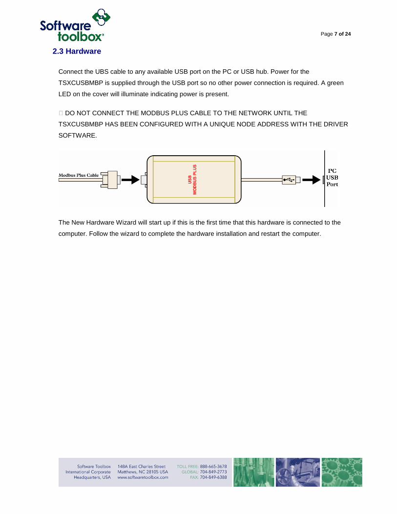
2.3 Hardware
Connect the UBS cable to any available USB port on the PC or USB hub. Power for the
TSXCUSBMBP is supplied through the USB port so no other power connection is required. A green
LED on the cover will illuminate indicating power is present.
� DO NOT CONNECT THE MODBUS PLUS CABLE TO THE NETWORK UNTIL THE
TSXCUSBMBP HAS BEEN CONFIGURED WITH A UNIQUE NODE ADDRESS WITH THE DRIVER
SOFTWARE.
The New Hardware Wizard will start up if this is the first time that this hardware is connected to the
computer. Follow the wizard to complete the hardware installation and restart the computer.

Page 8 of 24
3. TSXCUSBMBP Configuration
3.1 Access from the System Tray
During the installation of the software, the TSXCUSBMBP driver is added to the Startup group. Upon
power up of the computer, the driver will start and scan for attached devices. An icon will appear in the
system tray indicating the status of the driver.
• Indicates that a TSXCUSBMBP is found and initialized.
• Indicates that a TSXCUSBMBP is in the process of being initialized.
• Indicates that no TSXCUSBMBP is found.
3.1.1 Exit Driver
Right clicking on the TSXCUSBMBP icon and selecting Exit Driver will close the driver and break the
connection to the TSXCUSBMBP. The driver will need to be restarted manually by running the MbSvr.exe
application. By default, the application is installed in the following location:
C:\Program Files\Schneider Electric\TSXCUSBMBP\
Or the application can be started from the Start menu:
Start, All Programs, Schneider Electric, TSXCUSBMBP
3.1.2 Rescan Adapters
Right clicking on the TSXCUSBMBP icon and selecting Rescan Adapters will initiate a scan to identify a
connected TSXCUSBMBP. A rescan is necessary if the computer is powered up without the
TSXCUSBMBP being connected. This state will be indicated by a red icon. If a rescan is completed and

Page 9 of 24
no adapter is found, check the USB cable and confirm that power is applied on the adapter using the
LEDs on the housing. Then confirm that the correct drivers are installed and enabled.
3.1.3 Show Interface
Double clicking or right clicking on the TSXCUSBMBP icon and selecting Show Interface will display the
Interface Window
3.2 Configure the Driver
The Interface Window is used to configure the TSXCUSBMBP adapter. The title bar of the window
displays the current node that is already selected for the adapter. Information on initialized adapters is
displayed as well as a window for status and error information.
Page 10 of 24
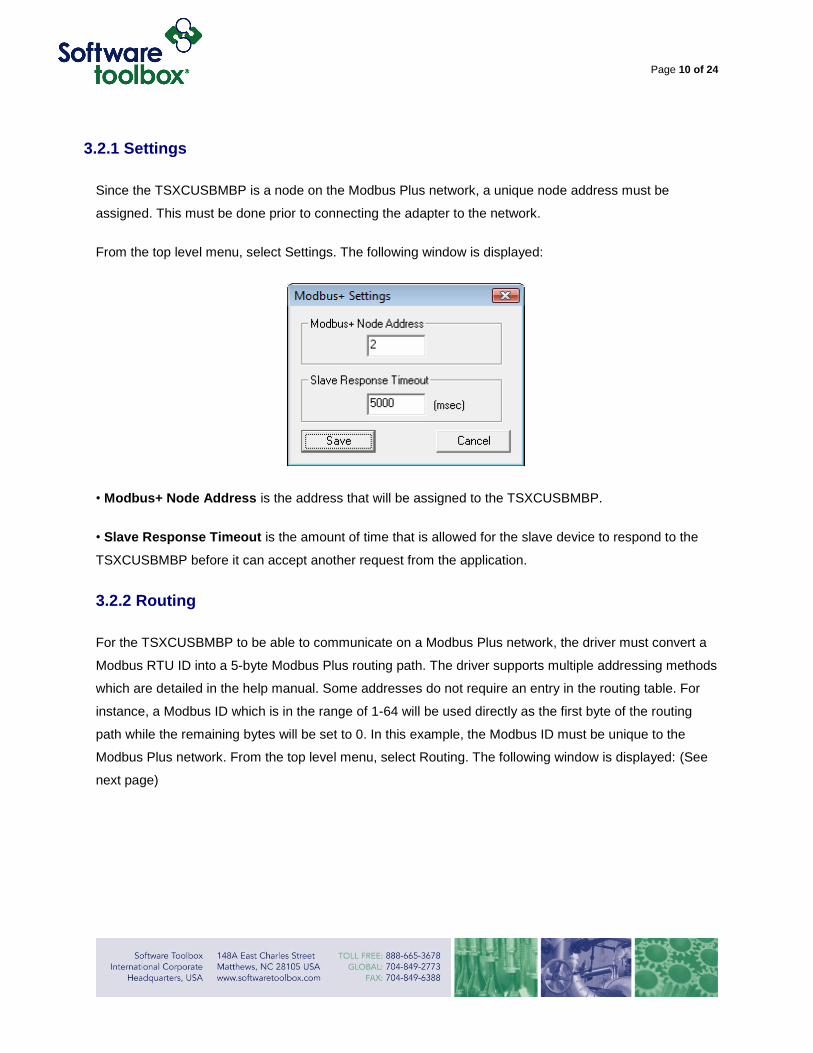
3.2.1 Settings
Since the TSXCUSBMBP is a node on the Modbus Plus network, a unique node address must be
assigned. This must be done prior to connecting the adapter to the network.
From the top level menu, select Settings. The following window is displayed:
• Modbus+ Node Address is the address that will be assigned to the TSXCUSBMBP.
• Slave Response Timeout is the amount of time that is allowed for the slave device to respond to the
TSXCUSBMBP before it can accept another request from the application.
3.2.2 Routing
For the TSXCUSBMBP to be able to communicate on a Modbus Plus network, the driver must convert a
Modbus RTU ID into a 5-byte Modbus Plus routing path. The driver supports multiple addressing methods
which are detailed in the help manual. Some addresses do not require an entry in the routing table. For
instance, a Modbus ID which is in the range of 1-64 will be used directly as the first byte of the routing
path while the remaining bytes will be set to 0. In this example, the Modbus ID must be unique to the
Modbus Plus network. From the top level menu, select Routing. The following window is displayed: (See
next page)

Page 11 of 24
Select the Modbus ID by clicking the entry on the table. The entry will become highlighted and the current
values will be populated in the fields below.
• Node is the slave address used by the application.
• Route is the Modbus Plus routing that is created be the structure of the network.
Press Update to apply the changes to the table.
Page 12 of 24
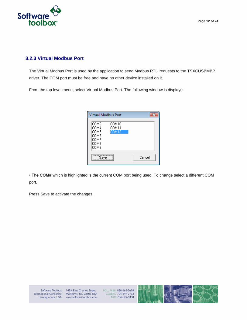
3.2.3 Virtual Modbus Port
The Virtual Modbus Port is used by the application to send Modbus RTU requests to the TSXCUSBMBP
driver. The COM port must be free and have no other device installed on it.
From the top level menu, select Virtual Modbus Port. The following window is displaye
• The COM# which is highlighted is the current COM port being used. To change select a different COM
port.
Press Save to activate the changes.

Page 13 of 24
3.2.4 MB+ Network Diagnostics
The TSXCUSBMBP driver also provides useful diagnostics functions such as a complete and local
network scan. Refer to the TSXCUSBMBP driver help manual for complete details on the diagnostic
tools.
From the top level menu, select MB+ Network Diagnostics. The following window is displayed:
When the diagnostic window is first opened, only the TSXCUSBMBP adapter will be displayed. A scan
must be performed to see other devices on the network.
Page 14 of 24
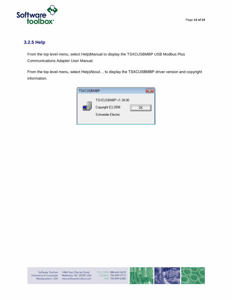
3.2.5 Help
From the top level menu, select Help|Manual to display the TSXCUSBMBP USB Modbus Plus
Communications Adapter User Manual.
From the top level menu, select Help|About… to display the TSXCUSBMBP driver version and copyright
information.

Page 15 of 24
4.TOP Server Configuration
4.1 Prerequisites
• The TSXCUSBMBP software and hardware must be installed and configured using the above
guidelines.
• TOP Server must be installed on a computer that meets the hardware requirements.
• A new or existing server project must be opened.
4.2 Set up the Server
Use the following procedure to create a new channel, device and tag for use with the TSXCUSBMBP
adapter.
4.2.1 Create a New Channel
1. Using the top level menu, select “Click to add a channel.”

Page 16 of 24
2. Enter a channel name. Press Next when complete.
3. Use the Device Driver: drop down menu to select the Modbus Serial driver. Press Next when complete.

Page 17 of 24
4. Use the ID: drop down menu to select the Virtual Modbus Port that was configured when setting up the
TSXCUSBMBP driver. All other parameters are ignored when using a Virtual Modbus Port. Press Next
when complete.
5. Make any optimizations that are necessary. For most cases, the default values will work correctly.
Press Next when complete.

Page 18 of 24
6. Review the summary and press Finish when complete.

Page 19 of 24
4.2.2 Create a New Device
1. Using the top level menu, select “Click to add a device.”
2. Enter a device name. Press Next when complete.

Page 20 of 24
3. Use the Device model: drop down menu to select Modbus. Press Next when complete.
4. Use the Device ID: drop down menu to select the slave ID that was configured in the Modbus Routing
Table when setting up the TSXCUSBMBP driver. If no entry was made in the Modbus Routing
Table,select the Modbus Plus node address of the device. Press Next when complete.

Page 21 of 24
5. Continue with the New Device wizard using the default values for the remaining pages. The values can
be modified at the device level at a later time.
6. Review the summary and press Finish when complete.

Page 22 of 24
4.2.3 Create a New Tag
1. Using the top level menu, select “Click to add a static tag”
2. Under the General tab, assign a name for the new tag. In this example, Modbus address
400001 is used in the address field. A description may also be entered. Press OK when
complete.

Page 23 of 24
4.3 Check the Connection
1. Using the top level menu, select OPC Quick Client button (the yellow arrow is designating
the Quick Client button on the screen below)
Page 24 of 24
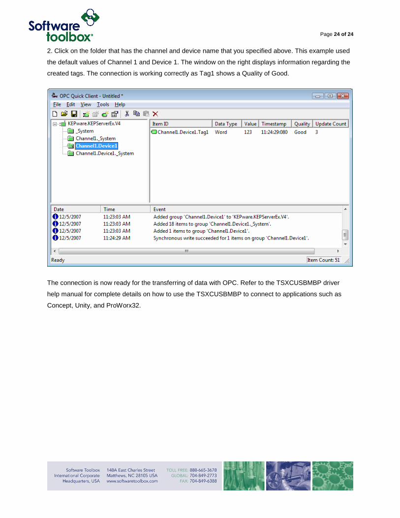
2. Click on the folder that has the channel and device name that you specified above. This example used
the default values of Channel 1 and Device 1. The window on the right displays information regarding the
created tags. The connection is working correctly as Tag1 shows a Quality of Good.
The connection is now ready for the transferring of data with OPC. Refer to the TSXCUSBMBP driver
help manual for complete details on how to use the TSXCUSBMBP to connect to applications such as
Concept, Unity, and ProWorx32.