QUICK START GUIDE WK-2x Access Point - YATUN
20
QUICK START GUIDE WK-2x Access Point WK-2, WK-2-B, WK-2-C / 802.11ac Dual Band Access Version 1.1
Transcript of QUICK START GUIDE WK-2x Access Point - YATUN
QUICK START GUIDE
WK-2x Access Point WK-2, WK-2-B, WK-2-C / 802.11ac Dual Band AccessVersion 1.1
2 3
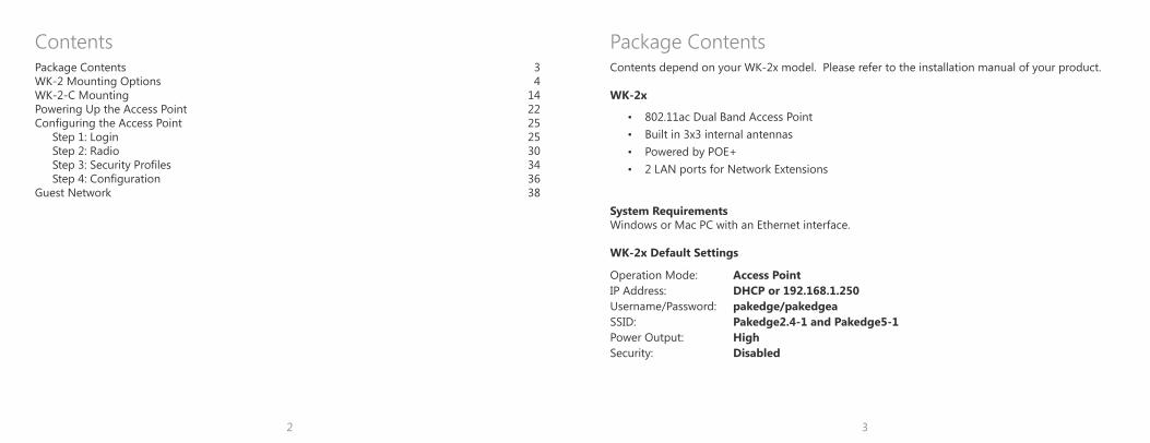
Package Contents 3WK-2 Mounting Options 4WK-2-C Mounting 14Powering Up the Access Point 22Configuring the Access Point 25
Step 1: Login 25Step 2: Radio 30Step 3: Security Profiles 34Step 4: Configuration 36
Guest Network 38
ContentsContents depend on your WK-2x model. Please refer to the installation manual of your product.
WK-2x
• 802.11ac Dual Band Access Point • Built in 3x3 internal antennas • Powered by POE+ • 2 LAN ports for Network Extensions
System RequirementsWindows or Mac PC with an Ethernet interface.
WK-2x Default Settings
Package Contents
Operation Mode: Access PointIP Address: DHCP or 192.168.1.250Username/Password: pakedge/pakedgeaSSID: Pakedge2.4-1 and Pakedge5-1Power Output: HighSecurity: Disabled
4 5
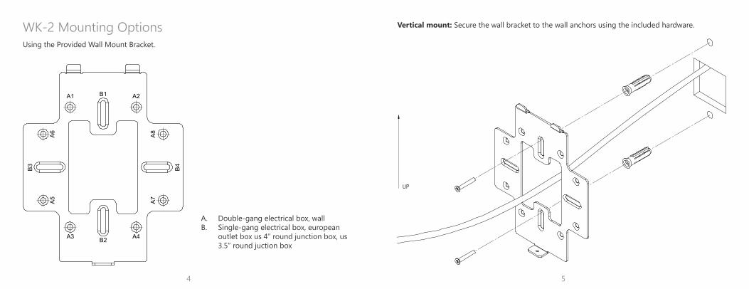
WK-2 Mounting Options Vertical mount: Secure the wall bracket to the wall anchors using the included hardware.
UP
A1 A2
A4A3
A6
A8
A7
A5
B4
B3
B2
B1
A. Double-gang electrical box, wallB. Single-gang electrical box, european
outlet box us 4” round junction box, us 3.5” round juction box
Using the Provided Wall Mount Bracket.
6 7
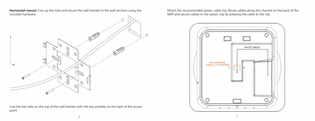
Line the two tabs on the top of the wall bracket with the two pockets on the back of the access point.
UP
Horizontal mount: Line up the slots and secure the wall bracket to the wall anchors using the included hardware.
Attach the recommended plastic cable clip. Route cables along the channel on the back of the WAP and secure cables to the plastic clip by pressing the cable to the clip.
ROUTE CABLES
RECOMMENDED CABLE CLIP PLACEMENT
8 9
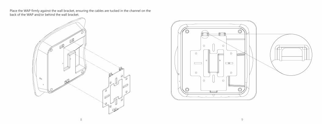
Place the WAP firmly against the wall bracket, ensuring the cables are tucked in the channel on the back of the WAP and/or behind the wall bracket.
10 11
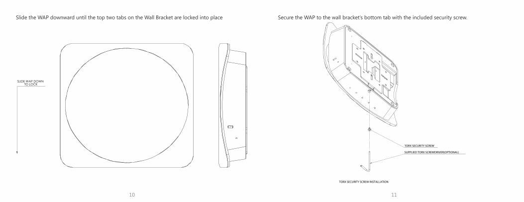
Slide the WAP downward until the top two tabs on the Wall Bracket are locked into place
SLIDE WAP DOWN TO LOCK
Secure the WAP to the wall bracket’s bottom tab with the included security screw.
SUPPLIED TORX SCREWDRIVER(OPTIONAL)
TORX SECURITY SCREW
TORX SECURITY SCREW INSTALLATION
12 13
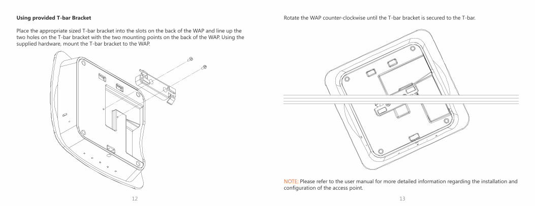
Using provided T-bar Bracket
Place the appropriate sized T-bar bracket into the slots on the back of the WAP and line up the two holes on the T-bar bracket with the two mounting points on the back of the WAP. Using the supplied hardware, mount the T-bar bracket to the WAP.
NOTE: Please refer to the user manual for more detailed information regarding the installation and configuration of the access point.
Rotate the WAP counter-clockwise until the T-bar bracket is secured to the T-bar.
14 15
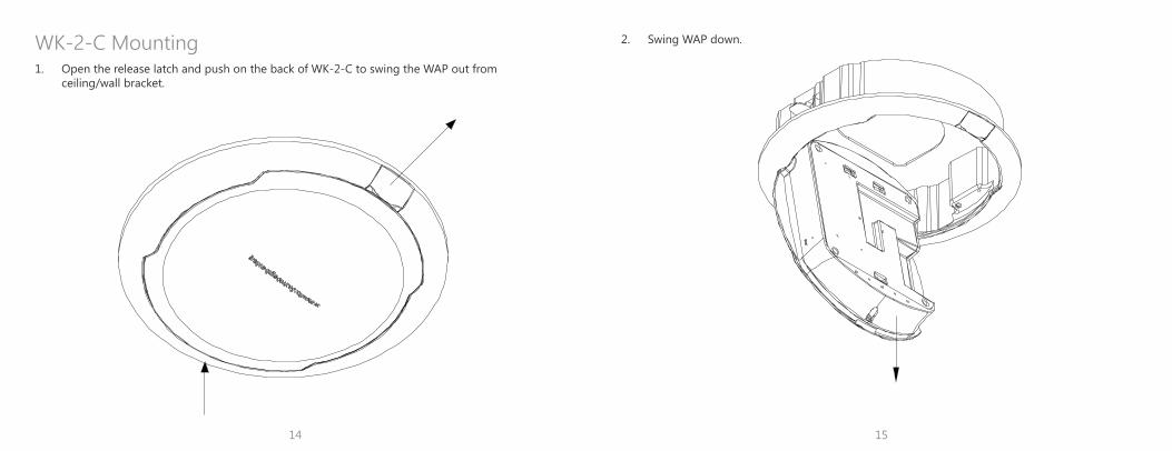
1. Open the release latch and push on the back of WK-2-C to swing the WAP out from ceiling/wall bracket.
WK-2-C Mounting 2. Swing WAP down.
16 17
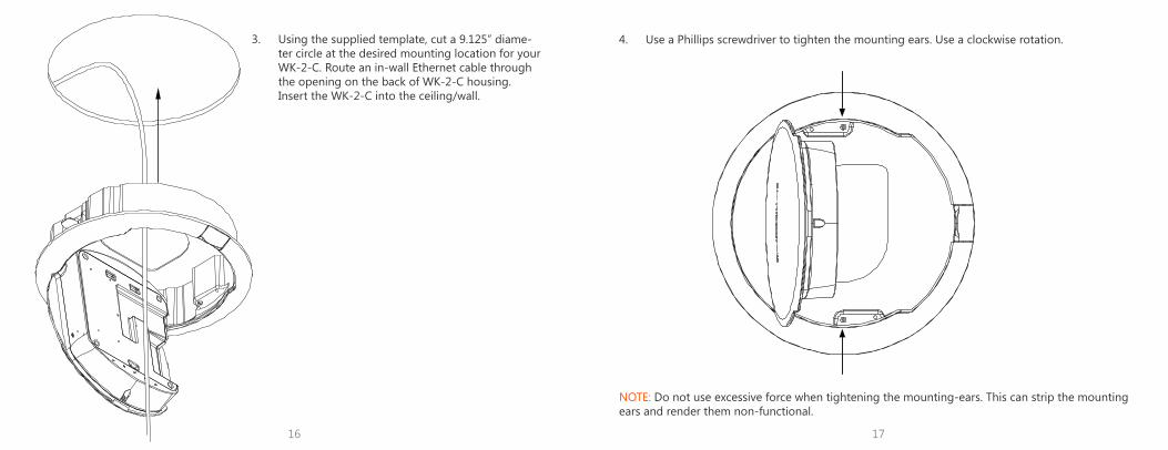
3. Using the supplied template, cut a 9.125” diame-ter circle at the desired mounting location for your WK-2-C. Route an in-wall Ethernet cable through the opening on the back of WK-2-C housing. Insert the WK-2-C into the ceiling/wall.
4. Use a Phillips screwdriver to tighten the mounting ears. Use a clockwise rotation.
NOTE: Do not use excessive force when tightening the mounting-ears. This can strip the mounting ears and render them non-functional.
18 19
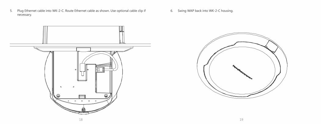
5. Plug Ethernet cable into WK-2-C. Route Ethernet cable as shown. Use optional cable clip if necessary.
6. Swing WAP back into WK-2-C housing.
20 21
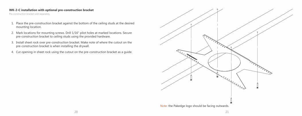
WK-2-C installation with optional pre-construction bracketPre-construction bracket sold separately.
1. Place the pre-construction bracket against the bottom of the ceiling studs at the desired mounting location.
2. Mark locations for mounting screws. Drill 1/16” pilot holes at marked locations. Secure pre-construction bracket to ceiling studs using the provided hardware.
3. Install sheet rock over pre-construction bracket. Make note of where the cutout on the pre-construction bracket is when installing the drywall.
4. Cut opening in sheet rock using the cutout on the pre-construction bracket as a guide.
Note: the Pakedge logo should be facing outwards.
22 23
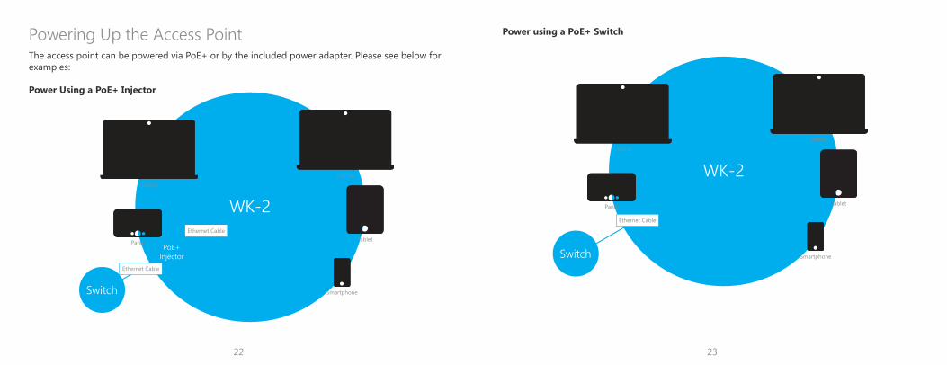
The access point can be powered via PoE+ or by the included power adapter. Please see below for examples:
Power Using a PoE+ Injector
Powering Up the Access Point
WK-2
Smartphone
Panel
Laptop
Laptop
Tablet
Switch
PoE+Injector
Ethernet Cable
Ethernet Cable
WK-2
Smartphone
Panel
Laptop
Laptop
Tablet
Switch
Ethernet Cable
Power using a PoE+ Switch
24 25
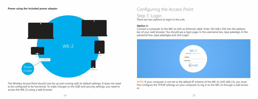
Power using the included power adapter
The Wireless Access Point should now be up and running with its default settings. It does not need to be configured to be functional. To make changes to the SSID and security settings, you need to access the WK-2x using a web browser.
WK-2
Smartphone
Panel
Laptop
Laptop
Tablet
PowerOutlet
AC Adapter
Step 1: LoginThere are two options to login to the unit:
Option 1:Connect a computer to the WK-2x with an Ethernet cable. Enter 192.168.1.250 into the address bar of your web browser. You should see a login page. In the username box, type pakedge. In the password box, type pakedgea and click Login.
NOTE: If your computer is not set to the default IP scheme of the WK-2x (192.168.1.X), you must first configure the TCP/IP settings on your computer to log in to the WK-2x through a web brows-er.
Configuring the Access Point
26 27
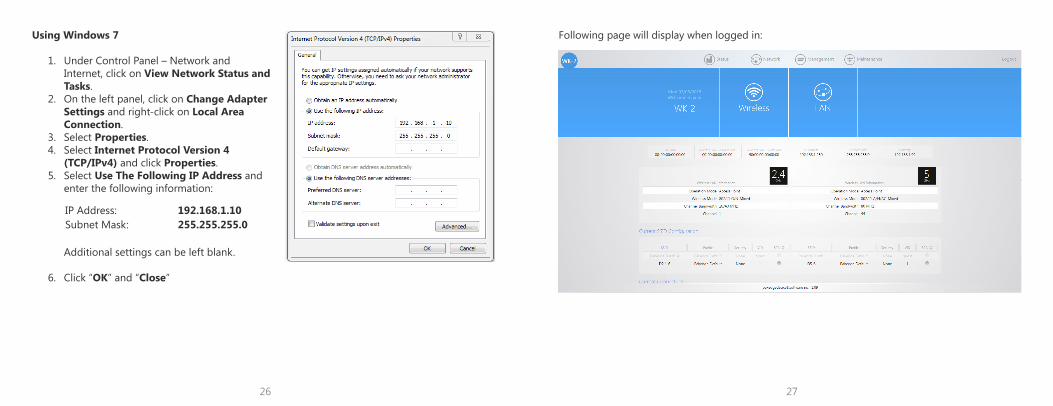
Using Windows 7
1. Under Control Panel – Network and Internet, click on View Network Status and Tasks.
2. On the left panel, click on Change Adapter Settings and right-click on Local Area Connection.
3. Select Properties.4. Select Internet Protocol Version 4
(TCP/IPv4) and click Properties.5. Select Use The Following IP Address and
enter the following information: Additional settings can be left blank.
6. Click “OK” and “Close”
IP Address: 192.168.1.10Subnet Mask: 255.255.255.0
Following page will display when logged in:
28 29
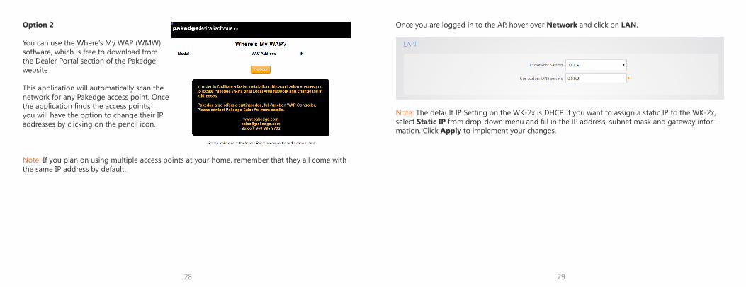
Option 2
You can use the Where’s My WAP (WMW) software, which is free to download from the Dealer Portal section of the Pakedge website
This application will automatically scan the network for any Pakedge access point. Once the application finds the access points, you will have the option to change their IP addresses by clicking on the pencil icon.
Note: If you plan on using multiple access points at your home, remember that they all come with the same IP address by default.
Once you are logged in to the AP, hover over Network and click on LAN.
Note: The default IP Setting on the WK-2x is DHCP. If you want to assign a static IP to the WK-2x, select Static IP from drop-down menu and fill in the IP address, subnet mask and gateway infor-mation. Click Apply to implement your changes.
30 31
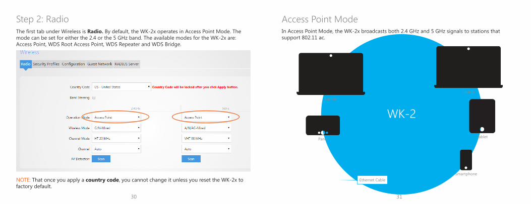
The first tab under Wireless is Radio. By default, the WK-2x operates in Access Point Mode. The mode can be set for either the 2.4 or the 5 GHz band. The available modes for the WK-2x are: Access Point, WDS Root Access Point, WDS Repeater and WDS Bridge.
Step 2: Radio
NOTE: That once you apply a country code, you cannot change it unless you reset the WK-2x to factory default.
WK-2
In Access Point Mode, the WK-2x broadcasts both 2.4 GHz and 5 GHz signals to stations that support 802.11 ac.
Access Point Mode
Smartphone
Panel
Laptop
Laptop
Tablet
Ethernet Cable
32 33
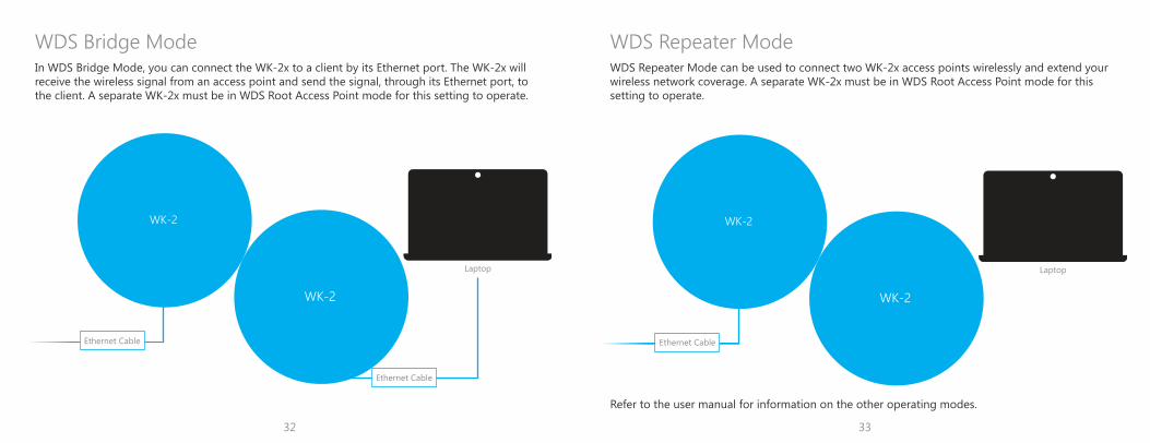
In WDS Bridge Mode, you can connect the WK-2x to a client by its Ethernet port. The WK-2x will receive the wireless signal from an access point and send the signal, through its Ethernet port, to the client. A separate WK-2x must be in WDS Root Access Point mode for this setting to operate.
WDS Bridge Mode
WK-2
WK-2
Laptop
Ethernet Cable
Ethernet Cable
WDS Repeater Mode can be used to connect two WK-2x access points wirelessly and extend your wireless network coverage. A separate WK-2x must be in WDS Root Access Point mode for this setting to operate.
WDS Repeater Mode
Refer to the user manual for information on the other operating modes.
WK-2
WK-2
Laptop
Ethernet Cable
34 35
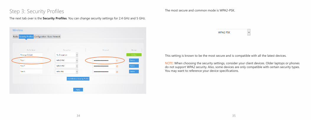
The next tab over is the Security Profiles. You can change security settings for 2.4 GHz and 5 GHz.
Step 3: Security Profiles The most secure and common mode is WPA2-PSK.
This setting is known to be the most secure and is compatible with all the latest devices.
NOTE: When choosing the security settings, consider your client devices. Older laptops or phones do not support WPA2 security. Also, some devices are only compatible with certain security types. You may want to reference your device specifications.
36 37
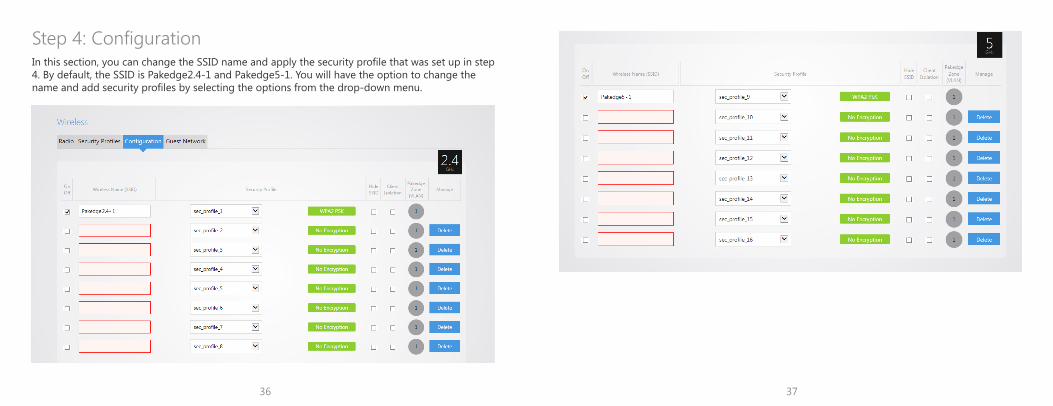
In this section, you can change the SSID name and apply the security profile that was set up in step 4. By default, the SSID is Pakedge2.4-1 and Pakedge5-1. You will have the option to change the name and add security profiles by selecting the options from the drop-down menu.
Step 4: Configuration
38
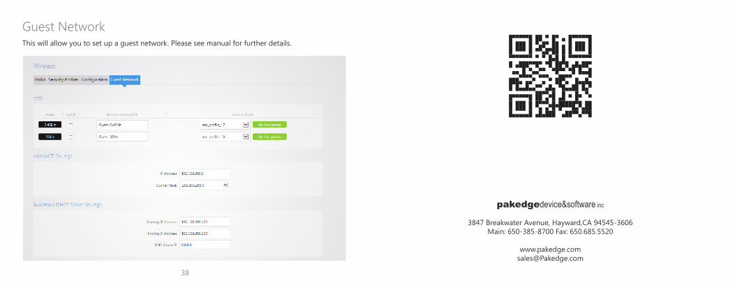
This will allow you to set up a guest network. Please see manual for further details.
Guest Network
pakedgedevice&software inc
3847 Breakwater Avenue, Hayward,CA 94545-3606Main: 650-385-8700 Fax: 650.685.5520