Quick Start Guide - InduSoftdownload.indusoft.com/81.0.0/IWS+v8.1+Quick+Start+Guide.pdfThis InduSoft...
104
Quick Start Guide
Transcript of Quick Start Guide - InduSoftdownload.indusoft.com/81.0.0/IWS+v8.1+Quick+Start+Guide.pdfThis InduSoft...

Quick Start Guide

Contents
Page 2
Contents
INTRODUCTION................................................................... 4Conventions used in this documentation............................................................................ 5About this software.............................................................................................................. 7About the InduSoft Web Studio software components......................................................13Install the full InduSoft Web Studio software.................................................................... 23Install EmbeddedView or CEView on a target device.......................................................33Execution Modes............................................................................................................... 38
THE DEVELOPMENT ENVIRONMENT............................. 40Title Bar..............................................................................................................................41Status Bar.......................................................................................................................... 42Application button.............................................................................................................. 43Quick Access Toolbar........................................................................................................ 44Ribbon................................................................................................................................ 46
Home tab.................................................................................................................... 46View tab...................................................................................................................... 47Insert tab.....................................................................................................................47Project tab...................................................................................................................48Graphics tab............................................................................................................... 48Format tab.................................................................................................................. 50Help tab...................................................................................................................... 50
Project Explorer................................................................................................................. 52Global tab................................................................................................................... 52Graphics tab............................................................................................................... 54Tasks tab.....................................................................................................................55Comm tab................................................................................................................... 57
Screen/Worksheet Editor................................................................................................... 59
ABOUT TAGS AND THE PROJECT DATABASE............. 60Understanding the Tag Name Syntax............................................................................... 62Choosing the Tag Data Type.............................................................................................63

Contents
Page 3
Using Array Tags............................................................................................................... 64About indirect tags.............................................................................................................68
TUTORIAL: BUILDING A SIMPLE PROJECT.................. 70Creating a new project...................................................................................................... 71Specifying the startup screen............................................................................................73Creating tags......................................................................................................................74Creating the main screen.................................................................................................. 76
Drawing the main screen's title..................................................................................78Drawing a button to open another screen................................................................. 80Saving and closing the main screen..........................................................................81
Creating the synoptic screen.............................................................................................82Drawing the synoptic screen's title.............................................................................82Drawing "Date" and "Time" displays.......................................................................... 83Placing an "Exit" icon................................................................................................. 84Testing the project...................................................................................................... 86Placing an animated tank...........................................................................................86Placing a level slider.................................................................................................. 89Drawing a tank selector............................................................................................. 91Testing the project...................................................................................................... 92
Configuring the communication driver...............................................................................93Monitoring device I/O during runtime.........................................................................96
Downloading your project to a Windows Embedded device............................................. 98Deploying your project as a web application.................................................................. 101

Introduction
Page 4
IntroductionInduSoft Web Studio (or IWS, for short) is a powerful, integrated tool thatexploits key features of Microsoft operating systems and enables you tobuild full-featured SCADA (Supervisory Control and Data Acquisition) orHMI (Human-Machine Interface) programs for your industrial automationbusiness.
This InduSoft Web Studio Quick Start Guide is intended for individuals usingIWS for the first time. This publication will help you quickly familiarizeyourself with the basic functions of IWS.

Introduction
Page 5
Conventions used in this documentationThis documentation uses standardized formatting and terminology to make iteasier for all users to understand.
Text conventionsThis documentation uses special text formatting to help you quickly identifycertain items:
• Titles, labels, new terms, and messages are indicated using italic text (forexample, Object Properties).
• File names, screen text, and text you must enter are indicated usingmonospace text (for example, D:\Setup.exe ).
• Buttons, menu options, and keyboard keys are indicated using a boldtypeface (for example, File menu).
In addition, this documentation segregates some text into Tip, Note, andCaution boxes:
• Tips provide useful information to save development time or to improvethe project performance.
• Notes provide extra information that may make it easier to understandthe nearby text, usually the text just before the note.
• Cautions provide information necessary to prevent errors that can causeproblems when running the project, and may result in damage.
Mouse and selection conventionsBecause most PCs used for project development run a version of MicrosoftWindows with a mouse, this documentation assumes you are using a mouse.Generally, a PC mouse is configured for right-handed use, so that the leftmouse button is the primary button and the right mouse button is thesecondary button.
This documentation uses the following mouse and selection conventions:
• Click and Select both mean to click once on an item with the left mousebutton. In general, you click buttons and you select from menus and lists.
• Double-click means to quickly click twice on an item with the left mousebutton.
• Right-click means to click once on an item with the right mouse button.

Introduction
Page 6
• Select also means you should use your pointing device to highlightor specify an item on the computer screen. Selecting an item with atouchscreen is usually the same as selecting with a mouse, except thatyou use your finger to touch (select) a screen object or section. To selectitems with your keyboard, you typically use the Tab key to move aroundoptions, the Enter key to open menus, and the Alt key with a letter key toselect an object that has an underlined letter.
• Drag means to press down the appropriate mouse button and move themouse before releasing the button. Usually an outline of the item willmove with the mouse cursor.
Windows conventionsThis documentation uses the following Windows conventions:
• Dialogs are windows that allow you to configure settings and enterinformation.
• Text boxes are areas in dialogs where you can type text.
• Radio buttons are white circles in which a black dot appears ordisappears when you click on the button. Typically, the dot indicates theoption is selected or enabled. No dot indicates the option is cleared ordisabled.
• Check boxes are white squares in which a check ( ) appears ordisappears when you click on it with the cursor. Typically, a check indicates the option is selected or enabled. No check indicates theoption is cleared or disabled.
• Buttons are icons in boxes appear "pressed" when you click on them.
• Lists are panes (white boxes) in windows or dialogs containing two ormore selectable options.
• Combo boxes have arrows that, when clicked, show part or all of anotherwise concealed list.
• Dockable windows are windows that you can drag to an edge of theinterface and merge with that edge.

Introduction
Page 7
About this softwareInduSoft Web Studio (IWS) is powerful software for developing HMI, SCADA,and OEE/Dashboard projects that can be deployed anywhere.
Each IWS project consists of:
• A project tags database to manage all run-time data, including bothinternal variables and I/O data;
• Configurable drivers to communicate in real-time with programmablelogic controllers (PLCs), remote I/O devices, and other data-acquisitionequipment;
• Animated human-machine interface (HMI) screens and overall equipmenteffectiveness (OEE) dashboards; and
• Optional modules such as alarms, events, trends, recipes, reports,scriptable logic, schedulers, a project security system, and a completedatabase interface.
After you develop your project, you can either run it locally on yourdevelopment workstation or download it to a remote computer and run itthere. The project runtime server processes I/O data from connected devicesaccording to your project parameters and then reacts to, displays, and/orsaves the data.
Product featuresActiveX and .NET
Use third-party controls to enhance your project. This softwareis a container for ActiveX and .NET controls. Add functionalitysuch as browsers, media players, charting, and other tools thatsupport the ActiveX and .NET interface standards.
AlarmsIn addition to all of the alarm functions you would expect, thissoftware also sends alarms using multi-media formats like PDF.Use remote notification to have alarms sent right to your emailinbox, a printer, or a smartphone! Alarms are real-time andhistorical, log data in binary format or to any database.
AnimationThis software gives you great command over graphics. Pasteimages, and even rotate them dynamically. Fill bar graphs

Introduction
Page 8
with color, or adjust the scale of objects with easy-to-useconfiguration. Other animations include "command" (for touch,keyboard and mouse interaction), hyperlink, text data link,color, resize (independent height and width), position, androtation (with custom rotation point).
DatabaseConnect to SQL databases (MS SQL, MySQL, Sybase, Oracle),MS Access and Excel, and ERP/MES systems (including SAP),even from Windows Embedded. Flexible enough to have a built-in interface without the need to know SQL (for trends, alarms/events, grid and other objects), or use any SQL statement youneed anywhere you need it.
DriversThis software includes over 240 built-in communication driversfor most PLCs, temperature controllers, motion controllers,barcode/RFID readers, and other devices. Also, InduSoft drivertoolkits allow you the flexibility to build your own drivers. Usethese built-in drivers without the need for OPC servers (but arean optional connection method).
EmailSend email via SMTP to any desktop or mobile device. Get real-time information on alarms, process values, and other events.This software supports SSL encryption allowing the use ofthird-party providers such as Gmail.
EventsThis software offers traceability for operator initiated actionsor internal system activity. Log events such as security systemchanges (user logon or off), screen open/close, recipe/reportoperations, custom messages and system warnings. Also anytag value changes including custom messages.
FDA TraceabilityTake advantage of built-in traceability and e-signaturefeatures to create projects that fully comply with U.S. Foodand Drug Administration regulations (Title 21 CFR Part 11).These features are often used in food and pharmaceutical

Introduction
Page 9
applications, but they can be used in any application wheretraceability is required.
FTPAutomatically upload or download files during run timeto/from remote storage locations using FTP and flexiblescripting functions. Configure FTP via scripting or the includedconfiguration interface.
Graphics and Design ToolsCreate powerful screens to meet any application need usingthe improved tools in our graphic interface. Combine built-inobjects to create any functionality required. Store graphics inthe symbol library for future use. Easily make projects across aproduct line share a consistent "look and feel".
Historical PerformanceWe have optimized the trend history module and designedit to load millions of values from SQL relational databaseswith high performance, with built-in data decimation in theTrend Control. Easy-to-use tools provide quick access toStatistical Process Control (SPC) values without any need forprogramming.
Intellectual Property ProtectionScreens, documents, scripts and even math worksheets can beindividually password protected. This prevents unauthorizedviewing or editing of your corporate custom functionality.Protect the entire project with just a few mouse clicks.
Multi-LanguageDevelop your project in one of many development languages,including English, Portuguese, German, and French.
OPCAs an alternative to the built-in drivers for directcommunication with PLCs, you can also use any of severaldifferent versions of OLE for Process Control (OPC) to manageyour devices. This software includes support for "classic"OPC DA (server or client), OPC HDA (server), OPC UA (client),OPC .NET (client), and OPC XML-DA (client).

Introduction
Page 10
PDF ExportSend Alarms, Reports, or any file (including .doc or .txt) to aproduction supervisor, quality manager, or maintenance staffusing the included PDF writer.
RecipesSave time and maintain consistency by automating partparameters or productions quantities with any triggering event.
RedundancyFor critical applications where data is vital, this softwaresupports web server, database and overall system redundancy.
ReportsCreate clear, concise reports in text format, graphical RTF,XML, PDF, HTML, and CSV, or integrate with Microsoft Office.Get the data you need, in the format you need it, to makeinformed decisions, fast.
ScalableDevelop once and deploy anywhere, on any currently supportedversion of Microsoft Windows.
SchedulerSchedule custom tag changes on date/time, frequency, orany trigger. Use this for simulation, to trigger reports or otherfunctionality at a particular time of day, or even to trigger driverworksheets to read/write at a scan rate you choose.
ScriptingTwo powerful scripting languages are supported. Use built-infunctions or use standard VBScript to take advantage of widelyavailable resources. Both can be used simultaneously to giveyou the functionality you need.
SecurityThis software provides support for group and user accounts, e-signatures, and traceability, as well as support for LightweightDirectory Access Protocol (LDAP). Integrate your project withyour Active Directory, including Active Directory ApplicationMode (ADAM).
Introduction
Page 11
SSL Support for EmailsNative support for Secure Socket Layer (SSL), which makes iteasy and secure to send emails from this software using third-party tools such as Gmail!
StandardsTake advantage of common industry standards to developprojects that are compatible with any format. TCP/IP,ActiveX/.NET, OPC (client and server), ODBC/ADO, COM/DCOM, OLE, DDE, XML, SOAP, and HTML are all supported.
SNMPEasily configure managed networked devices on IP networks(such as switches and routers) using incorporated SNMPconfiguration commands and an easy-to-use configurationinterface.
SymbolsAn extensive library of pre-made symbols features pushbuttons, pilot lights, tanks, sliders, meters, motors, pipes,valves and other common objects. Use the included symbolsin your project, modify existing symbols to suit your needs,or create your own from scratch. Plus support for third-partysymbol libraries and graphic tools.
Tags DatabaseThis software features an object-oriented tags database withboolean, integer, real, strings, arrays, classes (structures),indirect tags, and included system tags.
Thin ClientsRemotely view project screens on several different types ofthin clients. Use the standalone Secure Viewer to acheivethe greatest security on plant-floor stations. Use the InternetExplorer-based Web Thin Client to achieve the greatestflexibility on Windows desktops. Or use the HTML5-enabledMobile Access to access your project from almost any othercomputer or mobile device.
Trends

Introduction
Page 12
Real-time and Historical trends are supported. Log data inbinary format or to any database locally and remotely. Coloror fill trends with graphic elements to enhance clarity of data.Date/Time based or numeric (X/Y plot) trends give you theflexibility to display information that best suits your project.
TroubleshootingQuickly debug and verify a project using local and remotetools for troubleshooting, including status fields, DatabaseSpy and LogWin. Capture screen open and close times, seecommunications in real-time, and messages related to OPC,recipes/reports, security, database errors and even custommessages. Quickly get your project finished using thesepowerful tools.

Introduction
Page 13
About the InduSoft Web Studio software componentsThe InduSoft Web Studio software suite comprises several individualcomponents that can be installed on different platforms to perform differentfunctions. The architecture of your finished IWS project depends on whichcomponents you install, where you install them, and how you connect themto each other.
The following table lists all of the available components.
Component Features Platforms
InduSoft Web Studio • Project developmentenvironment
• Tag integration
• Remote management ofproject runtimes
• Project runtime
• Agent to allow remotemanagement
• Project thin client
• Windows
• Windows Server
• Windows Embedded Standard
EmbeddedView (incl. RemoteAgent)
• Project runtime (limited tagsand drivers)
• Agent to allow remotemanagement
• Project thin client
Windows Embedded Standard
CEView (incl. Remote Agent) • Project runtime (limited tagsand drivers)
• Agent to allow remotemanagement
• Project thin client
Windows Embedded Compact
IoTView (incl. Remote Agent) • Project runtime (limited tagsand drivers)
• Agent to allow remotemanagement
platform-agnostic
Studio Database Gateway(StADOSvr)
Enables communication betweenthe project runtime and external
• Windows

Introduction
Page 14
Component Features Platformsdatabases, including WonderwareHistorian and most ADO.NET-compatible databases.Should be installed separatelywhen using EmbeddedView orCEView, because most ADO.NETdata providers are not available onWindows Embedded.
Must be installed separately whenusing IoTView, because StudioDatabase Gateway runs only onWindows.
• Windows Server
Web Tunneling Gateway (WTG) Enables a public-facing web serverto pass data between the projectruntime and thin clients, when theproject runtime is located on asecure, private network.
Internet Information Services (IIS)for Windows
Mobile Access Runtime Enables the project runtimeto serve HTML5-enhancedproject screens to tablets andsmartphones.
• Internet Information Services(IIS) for Windows
• any CGI-enabled web server(e.g., Apache)
Secure Viewer (a.k.a. InduSoft ThinClient)
Project thin client, as a standaloneprogram.
• Windows
• Windows Server
• Windows Embedded Standard
• Windows Embedded Compact
Web Thin Client Project thin client, as a browseradd-on.
Internet Explorer for Windows
It is important to distinguish between the project development environmentand the project runtime. The project development environment enables youto design, develop, troubleshoot, deploy, and maintain IWS projects. Theproject runtime actually runs your project, communicates with externaldatabases and devices, and serves project screens to thin clients.
The full InduSoft Web Studio software includes both the project developmentenvironment and the project runtime. Your software license determineswhich parts of the software you can use. For more information, see ExecutionModes on page 38.

Introduction
Page 15
In contrast, EmbeddedView and CEView are runtime-only componentsfor Windows Embedded Standard and Windows Embedded Compact,respectively, and IoTView is a new, platform-agnostic runtime for otheroperating systems. They cannot be used for project development, so theyhave lower system requirements than the full InduSoft Web Studio software.
In most cases, the first thing you should do is install the full InduSoft WebStudio software on your primary workstation, because it not only sets upthe project development environment for you, it also unpacks the rest of thecomponents so that they can be installed on other computers and devices.
Tip: Separate installers for some components can be found on theInduSoft Web Studio installation media or downloaded from ourwebsite (www.indusoft.com).
Differences between the runtime editionsYou can develop projects once in the InduSoft Web Studio developmentenvironment and then run them on any of the runtime editions. This section

Introduction
Page 16
describes the differences between the editions, so that you can decide whichto use.
Deploy a project to any runtime edition
The following table shows the basic system requirements for each runtimeedition.
Requirement InduSoft WebStudio
EmbeddedView CEView IoTView
Windows 10 /Windows Server2016
Supported Not supported Not supported Contact us 3
Windows 8 /Windows Server2012
Supported Not supported Not supported Contact us 3

Introduction
Page 17
Requirement InduSoft WebStudio
EmbeddedView CEView IoTView
Windows 7 /Windows Server2008
Supported Not supported Not supported Contact us 3
WindowsEmbeddedStandard 8
Supported Supported Not supported Contact us 3
WindowsEmbeddedStandard 7
Supported Supported Not supported Contact us 3
WindowsEmbeddedCompact 2013
Not supported Not supported Supported Contact us 3
WindowsEmbeddedCompact 7
Not supported Not supported Supported Contact us 3
WindowsEmbeddedCompact 6 1
Not supported Not supported Supported Contact us 3
Linux (Debian-baseddistributions)
Not supported Not supported Not supported Supported (v8.0)
Wind RiverVxWorks
Not supported Not supported Not supported Supported (v8.0)
Available storage(hard drive or non-volatile)
2 GB 128 MB 64 MB 64 MB
Available memory(RAM)
1 GB 64 MB 32 MB 32 MB
1 Windows Embedded Compact 6 was formerly known as Windows CE 6.3 IoTView is a platform-agnostic runtime edition, which means it can run onmany different devices and operating systems. Only Linux and VxWorks arelisted as "Supported" because those are the only operating systems for whichwe have compiled and fully validated IoTView. If you want to run IoTViewon another device or operating system, contact your InduSoft Web Studiosoftware distributor.
For a complete list of system requirements for each runtime edition, see theinstallation instructions for that edition.

Introduction
Page 18
The following table shows the main differences in support for project featuresbetween the runtime editions. (The majority of features are fully supported inall editions, so they are not listed.) If you develop a project to include featuresthat are not supported in your chosen edition, you might see unexpectedbehavior and possibly even serious errors during run time. Some featureswill be automatically blocked in the project development environment whenyou select your project's target platform, but you should still be aware of thedifferences. For more information, see About target platforms, product types,and target systems.
Feature InduSoft WebStudio
EmbeddedView CEView IoTView
Run projectsdeveloped inInduSoft WebStudio
Supported Supported Supported Supported
Run as a Windowsservice
Supported Not supported Not supported Not supported
Local projectviewer
Supported Supported Supported Not supported
Server for SecureViewer
Supported Supported Supported Not supported
Server for WebThin Client
Supported Supported Supported Not supported
Support for MobileAccess
Supported Supported Not supported Supported
Support for MobileAccess Tabular
Supported Supported Supported Not supported
Email (SMTP client) Supported Supported Supported withlimitations 1
Not supported
Create tagsprogrammaticallyduring run time
Supported Not supported Not supported Not supported
Create screensprogrammaticallyduring run time
Supported Not supported Not supported Not supported
Save reports inPDF format
Supported Not supported Not supported Not supported
Built-in functions Supported Supported withlimitations 2
Supported withlimitations 2
Supported withlimitations 2

Introduction
Page 19
Feature InduSoft WebStudio
EmbeddedView CEView IoTView
Tag integration(a.k.a. SharedTags)
Supported Supported Supported Not supported
Security Supported Supported Supported Supported withlimitations 3
Procedures Supported Supported Supported Not supported 4
Event Logger Supported Supported Supported Not supported
Translation Supported Supported Supported Not supported
Alarms Supported Supported Supported Supported withlimitations 5
Trends Supported Supported Supported Supported withlimitations 6
Recipes Supported Supported Supported Not supported
Reports Supported Supported Supported Not supported
ODBC Supported Not supported 7 Not supported 7 Not supported 7
Math Supported Supported Supported Supported
Script Supported Supported Supported Not supported 4
Scheduler Supported Supported Supported Not supported
Database/ERP Supported Supported Supported Not supported
Drivers Supported Supported withlimitations 8
Supported withlimitations 8
Supported withlimitations 8
OPC DA 2.05 Client Supported Supported withlimitations 9
Supported withlimitations 9
Not supported
OPC DA 2.05Server
Supported Supported withlimitations 9
Supported withlimitations 9
Not supported
OPC UA Client Supported Supported Supported withlimitations 1
Supported withlimitations
OPC .NET Client Supported Not supported Not supported Not supported
OPC XML/DA Client Supported Not supported Not supported Not supported
DDE Client/Server Supported Not supported Not supported Not supported
TCP/IP Client/Server
Supported Supported Supported Not supported

Introduction
Page 20
Feature InduSoft WebStudio
EmbeddedView CEView IoTView
OPC HDA Server Supported Not supported Not supported Not supported
Screens Supported Supported Supported Supported
Screen Group Supported Supported Supported Supported
Graphic Script Supported Supported Supported Not supported 4
Screen Script Supported Supported Supported Not supported 4
Shapes Supported Supported Supported Supported
Active Objects Supported Supported Supported Supported withlimitations 10
Data Objects Supported Supported Supported see Mobile Access
Libraries >Symbols
Supported Supported withlimitations 11
Supported withlimitations 11
Supported withlimitations 11
Libraries > ActiveXControls
Supported Supported withlimitations 12
Supported withlimitations 12
Not supported
Libraries > .NETControls
Supported Not supported Not supported Not supported
Libraries > LinkedPictures
Supported Supported withlimitations 13
Supported withlimitations 13
see Mobile Access
Auto screenscaling
Supported Not supported 14 Not supported 14 see Mobile Access
Fill effects inshapes
Supported Supported withlimitations 15
Supported withlimitations 15
see Mobile Access
Ellipse objectstyles
Supported Not supported 16 Not supported 16 see Mobile Access
Hint (tooltip) Supported Supported Supported withlimitations 17
see Mobile Access
Command events Supported Supported withlimitations 18
Supported withlimitations 18
see Mobile Access
Rotation animation Supported Supported withlimitations 19
Supported withlimitations 19
see Mobile Access
Trend Control > Filleffects
Supported Not supported Not supported see Mobile Access
Trend Control >Export to File
Supported Not supported Not supported see Mobile Access

Introduction
Page 21
Feature InduSoft WebStudio
EmbeddedView CEView IoTView
Enhanced graphics(incl. anti-aliasing)
Supported Not supported Not supported see Mobile Access
Multi-touchgestures
Supported Supported Supported withlimitations 20
see Mobile Access
Number of projecttags
150, 300, 1500,4000, 16K, 32K,64K, 512K, or 10M
150, 300, 1500, or4000
150, 300, 1500, or4000
150, 300, 1500, or4000
Number ofsimultaneouslyconnected thinclients
0, 1, 2, 4, 8, 16, 32,64, or 128
0, 1, 2, 4, or 8 0, 1, 2, 4, or 8 0, 1, 2, 4, or 8(Mobile Accessonly)
Hardkey license(USB)
Supported Supported withlimitations 21
Supported withlimitations 21
Not supported
License Server Supported Not supported Not supported Not supported
1 Encryption (TLS/SSL) is not supported in CEView.2 Most of the functions are supported in all editions, but some specificfunctions are not supported in EmbeddedView/CEView or IoTView. For moreinformation, see List of available functions.3 Local mode only. Distributed and Domain modes are not supported inIoTView.4 VBScript is not supported in IoTView.5 Online alarms only. Alarm history is not supported in IoTView.6 Database format only. Proprietary and Historian formats are not supportedin IoTView.7 ODBC worksheets are a legacy feature, and they are not supported inEmbeddedView/CEView or IoTView. Use Database/ERP worksheets instead.8 Most of the drivers are supported in all editions, but some specificdrivers are not supported in EmbeddedView/CEView or IoTView. For moreinformation, see the documentation for each driver, which can be accessedthrough the project development environment: on the Help tab of the ribbon,in the Documentation group, click Communication Drivers.9 Single-thread only; multi-thread is not supported.10 Pushbutton, ListBox, and Smart Message objects are not supported. Minorlimitations in other objects.

Introduction
Page 22
11 A specific linked symbol is supported as long as all of its componentobjects and animations are also supported.12 A specific ActiveX object is supported as long as it is compiled for thetarget platform.13 BMP, JPG, and PNG images are supported, as long as the operatingsystem image on the Windows Embedded device also supports them. Formore information, see "Why are my linked pictures no longer displayed onWindows Embedded devices?" in the FAQ.14 Use the Convert Resolution command to scale your project screens for otherdisplay sizes. For more information, see Convert your project's displayresolution.15 Rectangle objects only.16 Default style only. Other styles (e.g., Arc, Chord, Ring) are not supported.For more information, see Ellipse object.17 The system tag Hint will be updated, but the actual tooltip will not bedisplayed on screen in CEView. For more information, see Object Propertiesdialog box.18 On Down, While Down, and On Up events only. For more information, seeCommand animation.19 Closed Polygon objects only.20 Zooming in screens, panning in screens, and rotating objects are notsupported in CEView. For more information, see About the different types ofmulti-touch gestures.21 Hardkeys provided by Wibu-Systems are supported. Hardkeys providedby Sentinel (SafeNet) are not supported. For more information, see Abouthardkey licenses.
Note: For a comprehensive list of supported features andlimitations in IoTView, see List of features supported in projectsrunning on IoTView.

Introduction
Page 23
Install the full InduSoft Web Studio softwareInstall the full InduSoft Web Studio software on your Windows computer inorder to develop IWS projects, or to use the computer as a project runtimeserver and/or thin client.
To install and run the full InduSoft Web Studio software, you must have:
• A Windows-compatible computer with a standard keyboard, a pointerinput (i.e., a mouse, trackpad, or touchscreen), and an SVGA-minimumdisplay;
• One of the following Windows operating systems:
• Windows 7 Service Pack 1
• Windows 8 (excluding RT)
• Windows 8.1
• Windows 10 (including LTSB versions)
• Windows Server 2008 R2 Service Pack 1
• Windows Server 2012
• Windows Server 2012 R2
• Windows Server 2016
• Windows Embedded 7 Standard
• Windows Embedded 8 Standard
• Windows 10 IoT Enterprise
• .NET Framework 3.5 (see note below);
• Microsoft Internet Explorer 6.0 or later;
• 2 GB free storage (hard drive or non-volatile);
• 1 GB free memory (RAM); and
• An Ethernet or Wi-Fi network adapter.
We recommend the Home Premium, Professional, Enterprise, and Ultimateeditions of Windows, because they include Internet Information Services(IIS) as a pre-installed feature that can be turned on. You can use IIS tomake your projects accessible to thin clients and mobile devices. We do notrecommend the Starter and Home Basic editions because they do not includeIIS, but you can still use them if you do not plan to use web-based features.

Introduction
Page 24
Even though you can install the full InduSoft Web Studio software on aWindows Embedded Standard computer, if you do not plan to developprojects on that computer and will use it only as a project runtime serverand/or client, you should consider installing EmbeddedView instead.EmbeddedView does not support as many project tags as the full software,but it requires fewer system resources and it can be installed and managedremotely.
Only Windows 8, Windows 8.1, Windows 10, Windows Server 2012, WindowsServer 2012 R2, and Windows Server 2016 are under what Microsoft calls"mainstream support", which means they are actively maintained andadditional service packs might be released for them in the future. Windows7 and Windows Server 2008 R2 are under what Microsoft calls "extendedsupport", which means they are no longer actively maintained. For moreinformation, go to: windows.microsoft.com/en-us/windows/lifecycle
Note: .NET Framework 3.5 is pre-installed in most recent versionsof Windows, but it might not be turned on by default. To turn it on,use the Programs and Features control panel.
In older versions of Windows, .NET Framework 3.5 must beinstalled separately. The InduSoft Web Studio software installerwill attempt to do this for you (see Step 2 below), but dependingon your computer's security settings, the installation might failwithout notice. If you experience problems later, while trying to runInduSoft Web Studio, use the Add/Remove Programs control panel toconfirm that .NET Framework 3.5 was installed successfully.
In Windows Server 2012 R2, .NET Framework 3.5 is not pre-installed and it cannot be installed by the InduSoft Web Studiosoftware installer. You must use the Server Manager utility toinstall it. For more information, see Install .NET Framework 3.5 inWindows Server 2012 R2.
Later versions of .NET Framework (e.g., .NET Framework 4.5) do notinclude .NET Framework 3.5.
The following items are optional but recommended:
• A USB port, to install the software from a USB flash drive.
This is optional because you can also download the installer over thenetwork to your computer.
• A USB port or memory card slot, to be used for hardkey licensing of thesoftware.
This is optional because softkey licensing is also available.

Introduction
Page 25
• Serial COM ports and adapters, to be used for direct communication withPLCs and other devices.
This is optional because many newer device protocols use TCP/IP orUDP/IP communication (i.e., Ethernet) instead of serial communication.
• Internet Information Services (IIS) installed and turned on, to makeyour projects accessible to mobile devices. For more information, see thedescription of the Mobile Access Runtime feature below.
This is optional because you may choose not to install the Mobile AccessRuntime feature now, as part of the full InduSoft Web Studio software. Youcan install it later, for either IIS or CGI.
• Microsoft Visual Studio 2010 or Team Explorer 2010 installed, to enableworkgroup collaboration and source control. For more information, seethe description of the Collaboration feature below.
This is optional because you may choose not to install the Collaborationfeature.
Finally, you must have Administrator privileges on the computer in order toinstall software.
To install the full InduSoft Web Studio software:
1. Close all other running programs, if possible.We recommend you do this because those programs can use a significantamount of system resources and therefore cause this installation to takelonger to finish. Windows services (e.g., Windows Defender, WindowsUpdate) can have the same effect, but we do not recommend you stop ordisable those services.
2. Do one of the following:
• Download the zipped installer to your computer, either from ourwebsite (www.indusoft.com) or from another location on yournetwork where you have previously saved it. Extract the files, openthe resulting folder, and then locate and run the setup program(setup.exe).
• Insert the installation drive into your USB port. If it does not autorun,locate and open the Welcome page (InduSoft.htm). When the pageis opened in your browser, click Product Installation and then follow theinstructions.
The installation wizard runs and asks you to select a language for theinstallation.
3. Select a language from the list, and then click OK.
Introduction
Page 26
This selection determines the language of the user interface for both theinstallation wizard and the project development environment. You canchange the language for the project development environment later, afterthe software has been installed.The wizard prepares for installation. During this step, it automaticallyinstalls SafeNet's Sentinel drivers (a part of the software licensingmechanism) and .NET Framework 3.5.
4. On the Welcome page of the wizard, click Next to proceed with theinstallation.
5. On the License Agreement page, click Yes to accept the agreement andproceed, or click No to refuse the agreement and exit the wizard.
6. On the Customer Information page, type your user name and company name,and then click Next.
7. On the Choose Destination Location page, select the folder where the softwareshould be installed, and then click Next.By default, the software will be installed at:
C:\Program Files (x86)\InduSoft Web Studio v8.1\
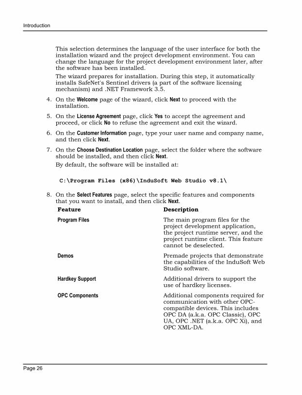
8. On the Select Features page, select the specific features and componentsthat you want to install, and then click Next.Feature Description
Program Files The main program files for theproject development application,the project runtime server, and theproject runtime client. This featurecannot be deselected.
Demos Premade projects that demonstratethe capabilities of the InduSoft WebStudio software.
Hardkey Support Additional drivers to support theuse of hardkey licenses.
OPC Components Additional components required forcommunication with other OPC-compatible devices. This includesOPC DA (a.k.a. OPC Classic), OPCUA, OPC .NET (a.k.a. OPC Xi), andOPC XML-DA.

Introduction
Page 27
Feature Description
PDF Printing Additional software that allowsrun-time reports to be saved asPDF files.
Security System Device Driver An additional keyboard driver thatenforces project security duringrun time by controlling user input.
Symbol Library A library of premade butconfigurable screen objects suchas pushbuttons, toggle switches,gauges, dials, indicator lights, andso on.
Windows CE Runtime Also called CEView — projectruntime software (server/client, but not development) forWindows Embedded Compact ona variety of processors. Check thedocumentation for your specificdevice to see what processor ituses.
Note: Selecting thisfeature will not actuallyinstall CEView on yourcomputer. It will simplyunpack the installationfiles and copy them toyour program folder, sothat you can later installCEView on a WindowsEmbedded Compactdevice.
Windows Embedded Runtime Also called EmbeddedView —project runtime software (server/client, but not development) forWindows Embedded Standardcomputers.
Note: Selecting thisfeature will not actuallyinstall EmbeddedViewon your computer. It

Introduction
Page 28
Feature Descriptionwill simply unpackthe installation filesand copy them to yourprogram folder, so thatyou can later installEmbeddedView on aWindows EmbeddedStandard computer
Windows Mobile Additional runtime software forolder Windows Mobile devices.
Mobile Access Runtime Additional software for InternetInformation Services (IIS) thatmakes your project runtimeaccessible to mobile devices suchas tablets and smartphones.
This feature requires that youhave IIS turned on and configuredwith ASP, ASP.NET, and ISAPIExtensions enabled. The InduSoftWeb Studio software installer willattempt to verify that you do, andif you do not, it will not install thisfeature.
For more information, see Turn onIIS for thin client access.
You do not need to install thisfeature at this time. You caninstall it later, after you haveturned on IIS, or you can installit on another computer that isacting as your project runtimeserver. There is a separate MobileAccess Runtime software installer(MobileAccessSetup.exe) thatis unpacked with the rest of theInduSoft Web Studio software.
To use this feature, your softwarelicense must include the MobileAccess Runtime option. For moreinformation, see About licensesettings. To purchase the option,

Introduction
Page 29
Feature Descriptioncontact your software distributor.You may still develop projects thatinclude Mobile Access features,even without the option, but clientswill not be able to access themduring run time.
Collaboration Additional tools for workgroupcollaboration and source controlwithin the InduSoft Web Studioproject development environment.
This feature requires that youhave Microsoft Visual Studio TeamExplorer 2010 installed on thesame computer. The InduSoftWeb Studio software installer willattempt to verify that you do, andif you do not, it will not install thisfeature.
The Team Explorer module isincluded in some versions ofMicrosoft Visual Studio 2010,so if you already have VisualStudio installed on your computer,you might be able to select andinstall the Collaboration feature.However, if you do not haveVisual Studio installed, or if youare not sure that your versionof Visual Studio includes theTeam Explorer module, you canseparately download and installTeam Explorer 2010 for free.
To download Team Explorer 2010,go to: www.microsoft.com/en-us/download/details.aspx?id=329
Note: Team Explorer2012 and Team Explorer2013 are not supportedas collaboration clients atthis time.

Introduction
Page 30
Feature DescriptionYou should also have MicrosoftVisual Studio Team FoundationServer 2010 or 2012 runningsomewhere on your network, but ifyou do not, it will not prevent youfrom installing the Collaborationfeature now.
Note: Team FoundationServer 2013 is notsupported at this time forthe collaboration server.
To use this feature, yoursoftware license must include theCollaboration option. For moreinformation, see About licensesettings. To purchase the option,contact your software distributor.
Wonderware Historian Installs the files that are requiredin order to save historical data(e.g., from Trend worksheets)to Wonderware Historian andWonderware Online databases.
To use this feature, yoursoftware license must include theWonderware Historian option.For more information, see Aboutlicense settings. To purchase theoption, contact your softwaredistributor.
9. On the Ready To Install page, click Install.
Note: You might receive the following error message duringinstallation: "Error 1628: Failed to complete script based install."For more information about this error and how to resolve it,go to: flexeracommunity.force.com/customer/articles/en_US/ERRDOC/Error-1628-Failed-To-Complete-Script-Based-Install

Introduction
Page 31
Note: If you try to install an older version (e.g., v7.1+SP3) ofthe InduSoft Web Studio software on a computer that alreadyhas a newer version (e.g., v8.1) installed, you might receivethe following message during installation: "Version x.x.x.x ofCodeMeter Development Kit is already installed. Downgradingto Version x.x.x.x is not possible, installation will be aborted."CodeMeter is supplemental software used by InduSoft WebStudio to manage hardkey licenses. To resolve this issue, youmust use Task Manager in Windows to stop CodeMeter RuntimeServer (CodeMeter.exe) before you install the older version ofInduSoft Web Studio.
The software is installed, and then when the installation is finished, thelast page of the wizard is displayed.
10.Click Finish to close the installation wizard.
When you have finished the installation, you can find the software in yourWindows Start menu at: Start > All Apps > InduSoft Web Studio v8.1
Note: In Windows 7, the software should be located at: Start > AllPrograms > InduSoft Web Studio v8.1
The software includes the following "apps" (applications):IWS v8.1 InduSoft Web Studio
The project development environment, runtime server, and thinclient. Its capabilities are determined by your software license.
IWS v8.1 Help ManualA complete technical reference and user guide for all of theInduSoft Web Studio software.
IWS v8.1 Quick Start GuideA brief guide to installing and using the project developmentenvironment, including a tutorial for developing a simpleproject.
IWS v8.1 RegisterA utility program that manages your InduSoft Web Studiosoftware license.
IWS v8.1 Release NotesA list of changes in the InduSoft Web Studio software.
IWS v8.1 Remote Agent

Introduction
Page 32
A utility program that allows InduSoft Web Studio running onother computers to connect to your computer and send projectsto it.
IWS v8.1 StartUpA shortcut that automatically starts the project runtime andruns the most recent project.
There should also be a shortcut icon on your desktop.
To run the software, do one of the following:
• Double-click the shortcut icon on your desktop; or
• Click Start > All Apps > InduSoft Web Studio v8.1 > IWS v8.1 InduSoft Web Studio.
If the installation failed for any reason, you can use System Restore torestore the computer to the restore point that was created at the beginningof the installation. For more information about System Restore, go to:support.microsoft.com/help/17127/windows-back-up-restore

Introduction
Page 33
Install EmbeddedView or CEView on a target deviceInstall EmbeddedView on a Windows Embedded Standard computer, orinstall CEView on a Windows Embedded Compact device, to use it as aproject runtime server and/or project thin client.
Note: If EmbeddedView or CEView is pre-installed on thetarget device, you may skip this entire task. Many hardwaremanufacturers pre-install the runtime software on their devices, aspart of a larger InduSoft Web Studio package.
Before you begin this task, you must have already installed the full InduSoftWeb Studio software on your computer, either from the installation disc orfrom the downloadable installer, because the redistributable EmbeddedViewand CEView software is included in the InduSoft Web Studio program folder.For more information, see Install the full InduSoft Web Studio software onpage 23.
To install and run EmbeddedView or CEView, you must have:
• A Windows Embedded-compatible device (hereafter called "the targetdevice");
• A Windows Embedded operating system that is currently supported byMicrosoft, which at this time includes:
• Windows Embedded 7 Standard
• Windows Embedded 8 Standard
• Windows 10 IoT Enterprise
• Windows Embedded Compact 6 (formerly known as Windows CE 6)
• Windows Embedded Compact 7
• Windows Embedded Compact 2013
• 128 MB of free storage (hard drive or non-volatile) for the runtime. Morestorage might be required depending on your project size.
• 64 MB of free memory (RAM). More memory might be required dependingon your project size.
• An Ethernet or Wi-Fi network adapter, for TCP/IP networking.
The following items are optional but recommended:
• A USB port; and

Introduction
Page 34
• Serial COM ports and adapters, to be used for direct communication withPLCs and other devices.
This is optional because many newer device protocols use TCP/IPcommunication instead of serial communication.
Installing EmbeddedView or CEView on a target device is actually a two-part procedure. First, you will copy the Remote Agent utility to the targetdevice and then run it. Remote Agent allows you to connect from theproject development environment to the target device. And then, throughthis connection, you will install the rest of the EmbeddedView or CEViewsoftware.
To install EmbeddedView or CEView:
1. Turn on the target device and make sure it is connected to your TCP/IPnetwork.If Remote Agent is pre-installed on the target device, it will automaticallyrun at start up and you may skip the next step. Many hardwaremanufacturers pre-install Remote Agent on their devices, as part of alarger InduSoft Web Studio package.
2. Copy the Remote Agent utility to the target device, and then run it:a) Locate the correct version of the Remote Agent utility (CEServer.exe)
for the target device. All versions are stored in your InduSoft WebStudio program folder.
Remote Agent for Windows Embedded Standard is located at:
C:\Program Files (x86)\InduSoft Web Studio v8.1\Redist\WinEmbedded\Bin\CEServer.exe
Remote Agent for Windows Embedded Compact is located at:
C:\Program Files (x86)\InduSoft Web Studio v8.1\Redist\WinCE 5.0\processor\Bin\CEServer.exe
…where processor is the specific processor used by the target device.For more information, consult the manufacturer's documentation.
b) Copy CEServer.exe to the target device by either downloading it overthe network, transferring it on a USB flash drive, or syncing it withMicrosoft ActiveSync. (ActiveSync is also known as Windows MobileDevice Center in Windows Vista or Zune Software in Windows 7.) Youmay save the file anywhere you want on the target device, as long asit is in permanent (i.e., non-volatile) memory and it is not in the root
Introduction
Page 35
folder (i.e., C:\ on Windows Embedded Standard, or \ on WindowsEmbedded Compact).
c) Set Remote Agent to automatically run at start up.You can do this on most Windows Embedded Compact devices bycreating a link to it in \Windows\Startup. If this does not work onyour device, please refer to the manufacturer's documentation.
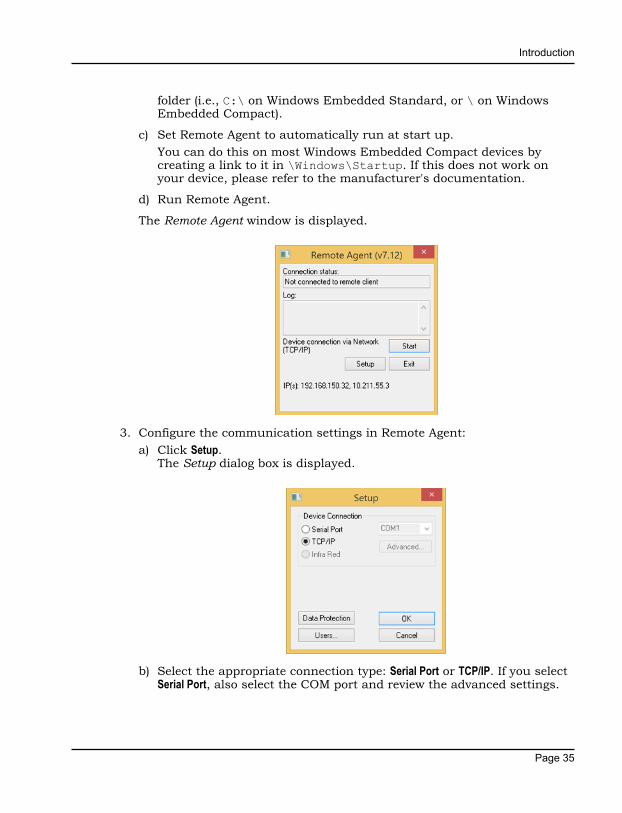
d) Run Remote Agent.
The Remote Agent window is displayed.
3. Configure the communication settings in Remote Agent:a) Click Setup.
The Setup dialog box is displayed.
b) Select the appropriate connection type: Serial Port or TCP/IP. If you selectSerial Port, also select the COM port and review the advanced settings.

Introduction
Page 36
If you are already connected to the target device via ActiveSync, youdo not need to select another connection at this time. However, keepin mind how the target device will actually be used during project runtime.
c) Click OK.
d) If you selected TCP/IP for the device connection, note the IP address.
e) Make sure that you leave Remote Agent running on the target device.
4. Use the Remote Management tool to connect to the target device:a) Run the project development application on your computer.
b) On the Home tab of the ribbon, in the Remote Management group, clickConnect.The Remote Management dialog box is displayed.
c) Select the appropriate connection type for the target device: Host, SerialPort, or Microsoft ActiveSync. If you select Host, also type the host name orIP address of the target device. If you select Serial Port, also select theCOM port and verify the advanced serial communication settings.
d) Click Connect.If you are successfully connected to the target device, the connectionstatus is shown in the Status box and the device's specifications areshown in the Platform box.
If you are not connected, check both the connection settings and thephysical connections. In particular, if you have selected Host as the

Introduction
Page 37
connection type, check to make sure that port 4322 is open on anyfirewalls between your computer and the target station, including onthe target station itself.
Note: In some cases, the Remote Management tool maynot be able to connect via Microsoft ActiveSync to a devicerunning Windows CE 6.0 or later. This is because of aproblem in the default configuration of Windows CE 6.0. Youcan fix the problem by using a small utility that is includedwith InduSoft Web Studio. The utility is located at:
C:\Program Files (x86)\InduSoft Web Studio v8.1\Redist\ActiveSyncUnlock.exe
Copy this file to the device using the stand-alone version ofMicrosoft ActiveSync and then execute the file on the device.It does not matter where the file is located on the device.When this is done, try again to use the Remote Managementtool to connect to the device.
If you still cannot connect via Microsoft ActiveSync, emptythe device's \Temp directory and try again.
5. Install the rest of the EmbeddedView or CEView software on the targetdevice:a) In Remote Management, click Install system files.
When the installation is finished, the target device's updated status isdisplayed in the Status box.
With EmbeddedView or CEView installed on the target device, you can nowuse it as a project runtime and/or thin client.
Note: Some run-time features are supported by the full InduSoftWeb Studio software but not by EmbeddedView and CEView. If youdevelop a project that uses any of these features and then try to runit in EmbeddedView or CEView, you might see unexpected behaviorand possibly even serious errors during run time. Some featureswill be automatically blocked when you change your project's targetplatform, but you should still be aware of the differences betweenruntime editions. For more information, see About the InduSoftWeb Studio software components on page 13.

Introduction
Page 38
Execution ModesInduSoft Web Studio, EmbeddedView, and CEView support the followingexecution modes:
Execution Mode InduSoft Web Studio EmbeddedView / CEView
Evaluation Mode Supported Not supported
Demo Mode Supported Supported
Licensed for Engineering Only Supported Not supported
Licensed for Runtime Only Supported Supported
Licensed for Engineering +Runtime
Supported Not supported
Evaluation ModeEnables all of the product's engineering and runtime features.
The first time you install InduSoft Web Studio on a computer,the product runs for forty (40) hours in Evaluation Mode. Thisevaluation period includes any time you run a product module(engineering or runtime). You can use this evaluation periodcontinuously or not; for example, 10 hours a day for 4 days, or5 hours a day for 8 days, or 10 hours a day for 3 days plus 5hours a day for 2 days, and so on.
After running for 40 hours in the Evaluation Mode, theevaluation period ends and the program automatically convertsto Demo Mode until you apply a valid license. You cannotreactivate Evaluation Mode, even if you reinstall the software onyour computer.
Note: Each version of InduSoft Web Studio hasan evaluation period that is independent of everyother version. For example, if your InduSoftWeb Studio v7.0 evaluation period has expiredand you are running in Demo Mode becauseyou have not installed a license, when youinstall InduSoft Web Studio v8.1 on the samecomputer, the newer version will begin its own40-hour evaluation period and the older versionwill continue running in Demo Mode.

Introduction
Page 39
Demo ModeAllows you to download projects to remote stations and torun projects for testing or demonstration purposes. You canexecute runtime tasks and use the debugging tools (LogWin andDatabase Spy), but they shut down automatically after runningfor two hours continuously. You can restart the Demo Modeagain and run for another two hours, and so on.
You cannot create or modify screens, worksheets, or projectsettings in Demo Mode.
Licensed for Engineering OnlyEnables all development options for an unlimited time.
This mode also allows you to continuously run the runtimetasks and debugging tools (Database Spy, Output window, andLogWin module) for 72 hours. After that period, these tasksshut down, but you can restart them and run for another 72hours, and so on. You can use this license for development andtesting only.
Licensed for Runtime OnlyEnables all runtime tasks and debugging tools (Database Spy,Output window, and LogWin module) for unlimited time, butyou cannot create or modify screens and/or worksheets.
The menu options available in Runtime Only mode are thesame as the options listed for Demo Mode (see previous table).
Licensed for Engineering + RuntimeEnables all development options, runtime tasks, and debuggingtools (Database Spy, Output window, and LogWin module) foran unlimited time.
Note: The Remote Management tool is always available, regardlessof the execution mode, so that you can upload files from ordownload files to remote stations.
To see which execution mode you are currently running, click About on theHelp tab of the ribbon; the About dialog shows the execution mode, includingthe time remaining if you are in Evaluation Mode.

The Development Environment
Page 40
The Development EnvironmentInduSoft Web Studio incorporates a modern, Ribbon-based Windowsinterface to provide an integrated and user-friendly developmentenvironment.
The IWS Development Environment

The Development Environment
Page 41
Title BarThe Title Bar located along the top of the development environment displaysthe application name (e.g., InduSoft Web Studio) followed by the name of theactive screen or worksheet (if any).
Example of Title Bar
The Title Bar also provides the following buttons (from left to right):
• Minimize button : Click to minimize the development environment windowto the Taskbar.
• Restore Down / Maximize: Click to toggle the development environmentwindow between two sizes:
• Restore Down button reduces the window to its original (default) size.
• Maximize button enlarges the window to fill your computer screen.
• Close button : Click to save the database and then close thedevelopment environment. If you modified any screens or worksheets,the application prompts you to save your work. This button's function issimilar to clicking Exit Application on the Application menu.
Note: Closing the development environment does not closeeither the project viewer or the runtime system, if they arerunning.

The Development Environment
Page 42
Status BarThe Status Bar located along the bottom of the development environmentprovides information about the active screen (if any) and the state of theapplication.
Example of Status Bar
The Status Bar fields (from left to right) are described in the following table:
Field Description
Execution Mode The current execution mode of the application.
CAP Indicates whether the keyboard Caps Lock is on(black) or off (grey).
NUM Indicates whether the keyboard Num Lock is on(black) or off (grey).
SCRL Indicates whether the keyboard Scroll Lock is on(black) or off (grey).
Object ID The ID number of a selected screen object.
Cursor Position The location of the cursor on the active screen orworksheet. If it's a screen, then the position of themouse cursor is given as X,Y coordinates, where X isthe number of pixels from the left edge of the screenand Y is the number of pixels from the top edge of thescreen. If it's a worksheet, then the position of the textcursor is given as Line and Column.
Object Size The size (in pixels) of a selected screen object, whereW is the width and H is the height.
No DRAG Indicates whether dragging is disabled (No DRAG) orenabled (empty) in the active screen.
Tag Count The total number of tags used so far in the project.

The Development Environment
Page 43
Application buttonThe Application button opens a menu of standard Windows applicationcommands like New, Open, Save, Print, and Close.
Application button opens menu of commands

The Development Environment
Page 44
Quick Access ToolbarThe Quick Access Toolbar is a customizable toolbar that contains a set ofcommands that are independent of the ribbon tab that is currently displayed.
Move the Quick Access ToolbarThe Quick Access Toolbar can be located in one of two places:
• Upper-left corner next to the Application button (default location); or
• Below the ribbon, where it can run the full length of the applicationwindow.
If you don't want the Quick Access Toolbar to be displayed in its currentlocation, you can move it to the other location:
1. Click Customize Quick Access Toolbar .
2. In the list, click Show Below Ribbon or Show Above Ribbon.
Add a command to the Quick Access ToolbarYou can add a command to the Quick Access Toolbar directly fromcommands that are displayed on the ribbon:
1. On the ribbon, click the appropriate tab or group to display the commandthat you want to add to the Quick Access Toolbar.
2. Right-click the command, and then click Add to Quick Access Toolbaron the shortcut menu.
You can also add and remove commands — as well as reset the toolbar to itsdefault — using the Customize dialog:
1. Click Customize Quick Access Toolbar .

The Development Environment
Page 45
2. In the list, click More Commands. The Customize dialog is displayed.
Customize Quick Access Toolbar dialog3. In the Choose commands from menu, select the appropriate Ribbon tab. The
commands from that tab are displayed in the Commands list.
4. In the Commands list, select the command that you want to add to theQuick Access Toolbar.
5. Click Add.
Only commands can be added to the Quick Access Toolbar. The contents ofmost lists, such as indent and spacing values and individual styles, whichalso appear on the ribbon, cannot be added to the Quick Access Toolbar.

The Development Environment
Page 46
RibbonThe new ribbon combines the numerous menus and toolbars from theprevious version of IWS into a single, user-friendly interface. Almost allapplication commands are now on the ribbon, organized into tabs andgroups according to general usage.
The Ribbon interface
Home tabThe Home tab of the ribbon is used to manage your project within thedevelopment environment.
Home tab of the ribbon
The tools are organized into the following groups:
• Clipboard: Cut, copy, paste, and find items in project screens and taskworksheets.
• Local Management: Run and stop the project on the local station (i.e., wherethe development application is installed), as well as manage the executiontasks. You can also run a project in Debug mode, for debugging VBScript.
• Remote Management: Connect to a remote station (e.g., a Windows Embeddeddevice) so that you can download the project to it, and then run, stop, andtroubleshoot the project on that station. For more information, see Aboutremote management.
The Development Environment
Page 47
• Tools: Miscellaneous tools to verify the project, import tags from otherprojects, convert screen resolutions, and register ActiveX and .NETcontrols.
• Tags: Manipulate tags and tag properties in the project database.
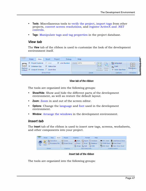
View tabThe View tab of the ribbon is used to customize the look of the developmentenvironment itself.
View tab of the ribbon
The tools are organized into the following groups:
• Show/Hide: Show and hide the different parts of the developmentenvironment, as well as restore the default layout.
• Zoom: Zoom in and out of the screen editor.
• Options: Change the language and font used in the developmentenvironment.
• Window: Arrange the windows in the development environment.
Insert tabThe Insert tab of the ribbon is used to insert new tags, screens, worksheets,and other components into your project.
Insert tab of the ribbon
The tools are organized into the following groups:

The Development Environment
Page 48
• Global: Insert tags, classes, translations, and procedures into the Globaltab of the Project Explorer.
• Graphics: Insert screens and screen groups into the Graphics tab of theProject Explorer.
• Task Worksheets: Insert task worksheets into the Tasks tab of the ProjectExplorer.
• Communication: Insert server configurations and communication worksheetsinto the Comm tab of the Project Explorer.
Project tabThe Project tab of the ribbon is used to configure your project settings.
Project tab of the ribbon
The tools are organized into the following groups:
• Settings: Configure the general project settings, set the project to run as aWindows service, or enable workgroup collaboration and version control.
• Security System: Enable and configure the project security system.
• Web: Configure the project to accept connections from a variety of thinclients.
Graphics tabThe Graphics tab of the ribbon is used to draw project screens.

The Development Environment
Page 49
Graphics tab of the ribbon
Note: This tab is available only when you have a project screenopen for editing.
The tools are organized into the following groups:
• Screen: Configure settings for the project screen itself, such as itsattributes, script, and background color or image.
• Editing: Select and edit objects in the project screen.
• Shapes: Draw static lines and shapes.
• Active Objects: Draw active objects, like buttons and check boxes.
• Data Objects: Draw objects that display historical data, like alarms, events,and trends.
• Libraries: Select from libraries of premade objects, such as symbols,ActiveX and .NET controls , external image files, and HTML5-basedcustom widgets.
• Animations: Apply animations to other screen objects.

The Development Environment
Page 50
Format tabThe Format tab of the ribbon is used to format and arrange objects in a projectscreen.
Format tab of the ribbon
Note: This tab is available only when you've selected one or moreobjects in a project screen.
The tools are organized into the following groups:
• Arrange: Arrange objects in a project screen, including bring to front andsend to back, group, align, and rotate.
• Position: Precisely adjust the position of a screen object in a project screen.
• Size: Precisely adjust the size of a screen object.
• Style: Change the fill and line color of a screen object.
• Fonts: Change the caption font of a screen object.
Help tabThe Help tab of the ribbon provides additional help with using the software.
Help tab of the ribbon
The tools are organized into the following groups:
• Documentation: Access the documentation for the development application,including this help file / technical reference and notes for the individualcommunication drivers.
The Development Environment
Page 51
• Information: Access other information about InduSoft Web Studio, includingthe license agreement, product website, and release notes, as well assystem and support details that make it easier for Customer Support toassist you.

The Development Environment
Page 52
Project ExplorerThe Project Explorer organizes all of the screens, worksheets, and other itemsthat comprise your project and presents them in an expandable tree-view.
To open a folder and view its contents, either click the Expand icon to theleft of the folder or double-click the folder itself.
To close a folder, click the Collapse icon to the left of the folder.
If you right-click any item in the Project Explorer, then a shortcut menu willappear with contextual commands for that item.
There are four main sections, or tabs, in the Project Explorer: Global,Graphics, Tasks, and Comm.
Global tabThe Global tab of the Project Explorer contains the project tags database, aswell as other features that apply to the entire project such as the securitysystem, VBScript procedures, and UI translation.
Global tab of the Project Explorer
The folders on the Global tab are described in the following sections:Project Tags
The project tags database contains all of the data tags that youcreate during project development, such as screen tags (e.g.,button1_state) or tags that read from / write to connecteddevices.
Classes

The Development Environment
Page 53
Classes are compound tags that you can create to associatea set of values, rather than a single value, with an object. Forexample, where you may normally create separate tags fora tank's pressure, its temperature, and its fill level, you caninstead create a "tank" class that includes all three.
Shared DatabaseThe shared database contains tags that were created in anotherprogram and then imported into or integrated with your project.
System TagsSystem tags are predefined values such as the date, the time,the name of the current user, and so on. You can use thesevalues to develop supervisory functions and housekeepingroutines.
All system tags are read-only, which means you cannot add,edit, or remove these tags from the database.
SecurityIf you choose to enable it, you can use the project securitysystem to control who may log on to your project and what theymay do during runtime.
ProceduresProcedures are VBScript functions and sub-routines that canbe called by any other script in your project.
Event LoggerThe event logger saves important runtime messages and taskresults to an external database.
TranslationYou can use the translation table to develop a multilingual userinterface (MUI) for your project.

The Development Environment
Page 54
Graphics tabThe Graphics tab of the Project Explorer contains all of the screens, screengroups, and symbols in your project.
Graphics tab of the Project Explorer
The folders on the Graphics tab are described in the following sections:Screens
You create screens to provide a graphical interface for yourproject. Each screen can contain many buttons, sliders, dials,indicators, graphs, and so on.
Screen GroupsYou can combine individual screens into screen groups, so thatthey all open together at the same time.
Thin ClientsYou can deploy your project as a web application to be accessedby thin clients such as desktop web browsers, tablets, andsmartphones. You can even deploy different versions of yourproject with different levels of functionality for each type ofclient.
Project SymbolsThis folder contains all of the custom symbols that you createfor your project. A symbol is a group of interconnected screenobjects that work together to perform a single function — forexample, lines, rectangles, and text fragments that have beenarranged to make a slider control.
Graphics ScriptYou can use this worksheet to define VBScript sub-routinesthat are called only when the graphics module starts (i.e.,
The Development Environment
Page 55
when a client station connects to the server and displays thegraphical interface), while it is running, and when it ends.
SymbolsThe symbols library contains not only the custom symbolsthat you create (see Project Symbols above), but also a largeselection of premade symbols that are installed with thedevelopment application.
LayoutThe layout editor displays all of the screens the are currentlyopen for editing. You can use it to visualize how the screens arearranged together and reuse screens in multiple layouts — forexample, to create a common navigation bar across your entireproject.
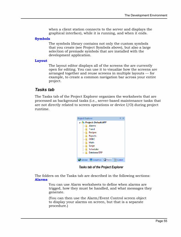
Tasks tabThe Tasks tab of the Project Explorer organizes the worksheets that areprocessed as background tasks (i.e., server-based maintenance tasks thatare not directly related to screen operations or device I/O) during projectruntime.
Tasks tab of the Project Explorer
The folders on the Tasks tab are described in the following sections:Alarms
You can use Alarm worksheets to define when alarms aretrigged, how they must be handled, and what messages theygenerate.
(You can then use the Alarm/Event Control screen objectto display your alarms on screen, but that is a separateprocedure.)

The Development Environment
Page 56
TrendsYou can use Trend worksheets to select project tags that shouldbe displayed as data trends and/or saved as historical data.
(You can then use the Trend Control screen object toactually display your trends on screen, but that is a separateprocedure.)
RecipesYou can use Recipe worksheets to select project tags that willload values from and/or save values to an external file. Theseworksheets are typically used to execute process recipes, butyou can store any type of information such as passwords,operation logs, and so on.
(You can then call the Recipe function to actually run aconfigured Recipe worksheet, but that is a separate procedure.)
ReportsYou can use Report worksheets to design runtime reports thatare either sent to a printer or saved to disk.
(You can then call the Report function to actually run aconfigured Report worksheet, but that is a separate procedure.)
ODBCYou can use ODBC worksheets to set up connections andexchange data with other ODBC-compliant databases.
MathYou can use Math worksheets to develop complex runtime logicusing the built-in scripting language.
ScriptYou can use Script worksheets to develop complex runtimelogic using VBScript.
SchedulerYou can use Scheduler worksheets to run commands atspecified times, dates, or trigger events.
DatabaseYou can use Database worksheets to set up connections andexchange data with external databases using the standardADO.NET interface (as an alternative to ODBC).

The Development Environment
Page 57
Comm tabThe Comm tab of the Project Explorer organizes the worksheets that controlcommunication with remote devices, using either direct communicationdrivers or other common protocols.
Comm tab of the Project Explorer
The folders on the Comm tab are described in the following sections:Drivers
You can use Driver worksheets to communicate with PLCsand other hardware, using any of the hundreds of directcommunication drivers that are installed with the developmentapplication.
OPC DA 2.05You can use OPC worksheets to communicate with OPC serversvia the OPC Classic protocol.
OPC UAYou can use OPC UA worksheets to communicate with OPCservers via the new OPC Unified Architecture protocol.
OPC .NetYou can use OPC .Net worksheets to communicate with OPCservers via the new OPC .NET 3.0 protocol (formerly OPC Xi).
OPC XML/DAYou can use OPC XML/DA worksheets to communicate withOPC servers via the new OPC XML-DA protocol.
TCP/IPYou can use TCP/IP worksheets to configure communicationbetween your own project and other IWS projects. The TCP/

The Development Environment
Page 58
IP Client and TCP/IP Server modules enable two or moreprojects to keep their databases synchronized using the TCP/IPprotocol.
DDEYou can use DDE worksheets to communicate with otherMicrosoft Windows applications, such as Microsoft Excel, thatsupport the Dynamic Data Exchange protocol.

The Development Environment
Page 59
Screen/Worksheet EditorUse the powerful, object-oriented screen editor to create and edit a varietyof screens and worksheets for your projects. You can input informationusing your mouse and keyboard, output control data to your processes, andautomatically update screens based on data input from your processes.
Screen/Worksheet Editor
Other screen editor features include:
• Simple point-and-click, drag-and-drop interface
• Grouping objects to preserve the construction steps of individual objects
• Editing objects without having to ungroup internal object components orgroups
• Handling bitmap objects and background bitmaps
• Status line support in project windows and dialogs

About Tags and the Project Database
Page 60
About Tags and the Project DatabaseTags are a core component of any IWS project. Simply put, tags are variablesused by IWS to receive and store data obtained from communication withplant floor devices, from the results of calculations and functions, and fromuser input. In turn, tags can be used to display information on screens (andWeb pages), to manipulate screen objects, and to control runtime tasks.
But tags are more than simple variables. IWS includes a real-time databasemanager that provides a number of sophisticated functions such as time-stamping of any value change, checking tag values against runtime minimumand maximum values, comparing tag values to alarming limits, and so on. AIWS tag has both a value and various properties that can be accessed, someat development and others only at runtime.
All tags are organized into one of the following categories, which arerepresented by folders on the Global tab of the Project Explorer:
• Project Tags are tags that you create during project development. Placeswhere project tags are used include:
• Screen tags
• Tags that read from/write to field equipment
• Control tags
• Auxiliary tags used to perform mathematical calculations
• Shared Database tags are created in a PC-based control program andthen imported into IWS's tags database.

About Tags and the Project Database
Page 61
For example you might create tags in SteepleChase and import them intoIWS so IWS can read/write data from a SteepleChase PC-based controlproduct.
You cannot modify shared tags within IWS — you must modify the tags inthe original PC-based control program, and then re-import them into theTags database.
• System Tags are predefined tags with predetermined functions that areused for IWS supervisory tasks. For example,
• Date tags hold the current date in string format
• Time tags hold the current time in string format
Most system tags are read-only, which means you cannot add, edit, orremove these tags from the database.
To see a list of the system tags, select the Global tab in the Project Explorer,open the System Tags folder, and open the Tag List subfolder. The abovefigure shows a partial list of system tags.
After creating a tag, you can use it anywhere within the project, and you canuse the same tag for more than one object or attribute.

About Tags and the Project Database
Page 62
Understanding the Tag Name SyntaxObserve the following guidelines when naming a tag:
• Your tag names must be unique — you cannot specify the same namefor two different tags (or functions). If you type an existing tag name, IWSrecognizes that the name exists and will not create the new tag.
• You must begin each tag name with a letter. Otherwise, you can useletters, numbers, and the underscore character (_) in your tag name.
• You cannot use the following symbols in a tag name:
` ~ ! @ # $ % ^ & * ( ) - = \ + \ [ ] { } < > ?
• You can use a maximum of 255 characters for a tag name or a classmember name.You can use uppercase and lowercase characters. Tagnames are not case sensitive. Because IWS does not differentiate betweenuppercase and lowercase characters, you can use both to make tag namesmore readable. (For example: TankLevel instead of tanklevel.)
• Tag names must be different from system tag names and math functions.
Note: Use the @ character at the beginning of a tag name toindicate that the tag will be used as an indirect tag in the project.
Some valid tag examples include:
• Temperature
• pressure1
• count
• x

About Tags and the Project Database
Page 63
Choosing the Tag Data TypeAnother consideration when designing a tag is what type of data the tag willreceive. IWS recognizes the following, standard tag data types:
• Boolean (one bit): Simple boolean with the possible values of 0 (false)and 1 (true). Equivalent to the "bool" data type in C++. Typically used forturning objects off and on or for closing and opening objects.
• Integer (four bytes): Integer number (positive, negative, or zero) internallystored as a signed 32-bit. Equivalent to the "signed long int" data type inC++. Typically used for counting whole numbers or setting whole numbervalues. Examples: 0, 5, −200.
• Real (floating point, eight bytes): Real number that is stored internally as asigned 64-bit. Equivalent to the "double" data type in C++. Typically usedfor measurements or for decimal or fractional values.
• String (alphanumeric data, up to 1024 characters): Character string upto 1024 characters that holds letters, numbers, or special characters.Supports both ASCII and UNICODE characters. Examples: Recipeproduct X123, 01/01/90, *** On ***.
You can also assign a new tag to a class that you have previously created.
You can find these tag types (and their respective icons) in the Global tab ofthe Project Explorer.

About Tags and the Project Database
Page 64
Using Array TagsIWS tags can consist of a single value or an array of values.
Note: The maximum array size is 16384 as long as it doesnot exceed the maximum number of tags supported by thelicense (Product Type) selected for the project. Each arrayposition (including the position 0) counts as one tag for licensingrestrictions, because each position has an independent value.
An array tag is a set of tags with the same name, which is identified byindexes (a matrix of n lines and 1 column). The maximum array size dependson the product specification. You can use the following syntax to access anarray tag:
ArrayTagName[ArrayIndex]
For example: tank[0], tank[1], tank[2], and tank[500].
Note: You must specify a maximum index for each array tag inthe size column of any datasheet. You can specify n to indicate thearray tag has positions from 0 to n. For example, if the size of TagAis 3, the tag elements could be TagA[0], TagA[1], TagA[2], andTagA[3].
Use the array tag whenever possible because it optimizes memory use andsimplifies the configuration task. For example, if you want a display tomonitor each tank, you could use array tags to configure a single displaycontaining tags linked to any tank. For example (using the tk tag as an indexcontaining the number of the tank): pressure[tk], temperature[tk], andtemperature[tk+1].
An array index can be a tag, a numeric value, or an expression with thearithmetic operator "+".
Note: When you refer to an array with an index using the +arithmetic operation, you must use the following syntax:
ArrayTagName[NumValue1+NumValue2]

About Tags and the Project Database
Page 65
Where NumValue1 and NumValue2 can be an integer tag ora numerical constant. For example: temperature[tk+2] ortemperature[tk+6].
Using array tags in any IWS task can save a signification amount of projectdevelopment time. For example, if you needed tag points related to thetemperature of four tanks. The conventional configuration method is thefollowing:
• temperature1: high temperature on tank 1
• temperature2: high temperature on tank 2
• temperature3: high temperature on tank 3
• temperature4: high temperature on tank 4
Using array tags simplifies this task, as follows:
• temperature[j]: high temperature on tank {j}
Note: When you create a four-position array tag, the systemcreates five positions (from 0 to 4). For example:
tag_example[15] //start position=0, end position=15
Therefore, the tag_example[15] array has 16 elements.
When using another tag to reference the index of an array, if the value of thetag is outside the size of the array, then the following results are given:
• If IndexTag is greater than the size of the array, thenMyArray[IndexTag] will point to the end position of the array; and
• If IndexTag is less than 0, then MyArray[IndexTag] will point to thestart position of the array.
Array TagsAn array tag consists of a set of tags that all have the same name, but useunique array indexes (a matrix of n lines and one column) to differentiatebetween each tag. An array index can be a fixed value, another tag or anexpression. Maximum array sizes are determined by product specifications.
You can use array tags to:
• Simplify configurations
• Enable multiplexing in screens, recipes, and communication interfaces

About Tags and the Project Database
Page 66
• Save development time during tag declaration
You specify array tags in one of two formats:
• For a simple array tag, type:
ArrayTagName[ArrayIndex]
• For a complex array tag (where the array index is an expression consistingof a tag and an arithmetic operation), type:
ArrayTagName[ArrayIndex+c]
Where:
• ArrayTagName is the tag name;
• [ArrayIndex] is the unique index (fixed value or another tag);
• + is an arithmetic operation; and
• c is a numerical constant.
Note:
• You must specify a maximum index for each array tag by typinga value (n) in the Array Size column of an Project Tags datasheetor in the Array Size field on a New Tag dialog. (See "Creatingproject database Tags").
When you create an n-position array tag, IWS actually createsn+1 positions (from 0 to n). For example, if you specifyArrayTag[15], the array will have 16 elements, where 0 is thestart position and 15 is the end position.
• You must not use spaces in an array tag.
When IWS reads a tag it begins with the first character andcontinues until it finds the first space or null character.Consequently, the system does not recognize any charactersfollowing the space as part of the array tag.
For example, if you type a[second + 1], IWS regards a[secondas the tag and considers it invalid because IWS does not find(recognize) the closing bracket. However, if you type a[second+1], this is a valid array tag.
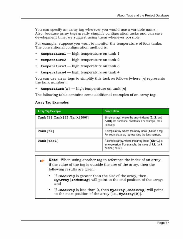
About Tags and the Project Database
Page 67
You can specify an array tag wherever you would use a variable name.Also, because array tags greatly simplify configuration tasks and can savedevelopment time, we suggest using them whenever possible.
For example, suppose you want to monitor the temperature of four tanks.The conventional configuration method is:
• temperature1 — high temperature on tank 1
• temperature2 — high temperature on tank 2
• temperature3 — high temperature on tank 3
• temperature4 — high temperature on tank 4
You can use array tags to simplify this task as follows (where [n] representsthe tank number):
• temperature[n] — high temperature on tank [n]
The following table contains some additional examples of an array tag:
Array Tag Examples
Array Tag Example Description
Tank[1], Tank[2], Tank[500] Simple arrays, where the array indexes (1, 2, and500) are numerical constants. For example, tanknumbers.
Tank[tk] A simple array, where the array index (tk) is a tag.For example, a tag representing the tank number.
Tank[tk+1] A complex array, where the array index (tk+1) isan expression. For example, the value of tk (tanknumber) plus 1.
Note: When using another tag to reference the index of an array,if the value of the tag is outside the size of the array, then thefollowing results are given:
• If IndexTag is greater than the size of the array, thenMyArray[IndexTag] will point to the end position of the array;and
• If IndexTag is less than 0, then MyArray[IndexTag] will pointto the start position of the array (i.e., MyArray[0]).

About Tags and the Project Database
Page 68
About indirect tagsIWS supports indirect access to tags in the database. For example, considera tag X of the String type. This tag can hold the name of any other tagin the database (that is, it can provide a pointer to any other type of tag,including a class type). The syntax for an indirect tag is straightforward:@IndirectTagName. For example, assume that a tag named X holds a "TEMP"string. Reading and/or writing to @X provides access to the value of the TEMPvariable.
Note: Any tag created as a string-type tag is potentially an indirecttag (pointer).
To refer to a class-type tag, you can declare a string-type tag that points to aclass tag. For example:
Class TANK with members Level
Tag TK of the class TANK
Tag XCLASS of the String type
To access the TK.Level value, you must store the " TK.Level" value withinthe XCLASS tag and use the syntax, @XCLASS. You can also refer to a memberof a class-type tag directly; identifying a class-type that points to a classmember.
For example:
Class TANK with members Level
Tag TK of the class TANK
Tag XCLASS of the class TANK
To access the TK.Level value, you must store the "TK" value within theXCLASS tag and use the syntax, @XCLASS.Level.
When creating tags for indirect use, place an X in the tag column ratherthan creating them as strings. For the type, write the type of tag for whichyou are creating a reference. Follow the XCLASS example: @Z Integer, @XClass:TANK.

About Tags and the Project Database
Page 69
Indirect TagsIndirect tags "point" to other database tags (including class-type tags). Usingindirect tags can save development time because they keep you from havingto create duplicate tags (and the logic built into them).
You create an indirect tag from any string-type tag simply by typing the @symbol in front of the tag name @TagName.
• To reference a simple tag, assume the strX tag (a string tag) holds thevalue "Tank", which is the name of another tag, then reading from orwriting to @strX provides access to the value of the Tank tag.
• To reference a class-type tag and member, you simply create a string tagthat points to the class tag and the member. For example, if a tag strX (astring tag) holds the value "Tank.Level", which is the name of the classtag, then reading from or writing to @strX provides access to the value ofthe Tank.Level member.
• You can also point directly to a class-type tag member; by identifyinga class-type that points to a class member. For example: to access theTank.Level member of the class, you must store the "Tank" value withinthe strX tag and use the syntax, @strX.Level.

Tutorial: Building a Simple Project
Page 70
Tutorial: Building a Simple ProjectThis section explains, using a step-by-step tutorial, how to build a simpleproject, as well as how to select and configure an I/O driver.

Tutorial: Building a Simple Project
Page 71
Creating a new projectThis part of the tutorial shows how to create a new project, including how togive it a name and select the target platform.
1. Click the Application button in the top-left corner of the developmentenvironment, and then click New on the Application menu..The New dialog is displayed.
2. Click the Project tab.
3. In the Project name box, type the name of your project.For this tutorial, type Tutorial.The development application automatically creates a new directory ofthe same name and assigns your project file to that directory. (Notice theConfiguration file text box in the figure.) To put your project file somewhereother than in the default projects folder, click Browse and navigate to thepreferred location.
4. In the Product type list, select the type of project that you want to build.For this example, select Windows Embedded Standard. This is a tag andfeature-limited product type that can be safely deployed on WindowsEmbedded devices.
Selecting the target platform and product type

Tutorial: Building a Simple Project
Page 72
5. Click OK.The New dialog is closed and the Project Wizard dialog is displayed.
6. In the Template list, select Empty Application.
7. In the Resolution list, select 640 x 480.
Specifying an empty Application with 640x480 resolution8. Click OK.
The Project Wizard dialog is closed and the new project is created in thedevelopment environment.

Tutorial: Building a Simple Project
Page 73
Specifying the startup screenThis part of the tutorial shows how to open the project settings and thenspecify which screen should be displayed on startup.
• Use the Information tab to provide information that identifies the project(such as project description, revision number, Company name, Author'sname, field equipment, and general notes).
• Use the Options tab to specify generic settings for the project, such as theTarget System, Automatic Translation, Alarm history and Events, DefaultDatabase and Shared Tags.
• Use the Viewer tab to enable/disable the runtime desktop parameters.
• Use the Communication tab to specify communication parameters relating tothe project in general.
• Use the Preferences tab to enable/disable warning messages when usingthe development application.
To specify the startup screen:
1. On the Project tab of the ribbon, in the Settings group, click Viewer.The Project Settings dialog is displayed with the Viewer tab selected.
2. In the Startup screen box, type main.scc.When you run the project, it will automatically display the main screen (orwhichever screen you specify) first. You can specify a screen before youcreate it, but if the screen has been created, then you can also select itfrom the list.
3. Click OK.

Tutorial: Building a Simple Project
Page 74
Creating tagsThis part of the tutorial shows how to create new tags by adding them to theProject Tags datasheet.
A tag is any variable that holds a value. All tags created in a project arestored in the Project Tags folder, on the Global tab of the Project Explorer.
Project Tags folder
1. In the Project Explorer, click the Global tab.
2. Double-click Project Tags to expand the folder.
3. Double-click Datasheet View to open the Project Tags datasheet.
4. Use the following parameters to create a tag for the sample project.a) Name: Specify a unique tag name. For this tutorial, type Level.
b) Array: Specify the top array index of the tag. (Simple tags have an Arrayof 0.) For this tutorial, type 3.
Each array index relates to one of the three tanks:
• Level[1] is the level of Tank #1
• Level[2] is the level of Tank #2
• Level[3] is the level of Tank #3
You will not use Level[0] in this tutorial, even though it is a valid tag.
c) Type: Specify the data type of the tag: Boolean, Integer, Real, String, orClass. For this tutorial, select Integer.
d) Description (optional): Type a description of the tag for documentationpurposes only.

Tutorial: Building a Simple Project
Page 75
e) Scope: Specify how the tag is managed between the Server and the ThinClient stations.
• Select Local if you want the tag to have independent values on theServer and Client stations.
• Select Server if you want the tag to share the same value on theServer and Client stations.
For this tutorial, select Server.
Creating the Level tag5. Save and close the Project Tags datasheet.
You will create additional tags as you build the project.
Tip: You can sort the data in the Project Tags datasheet or insert/remove additional columns by right-clicking on it and then choosingthe applicable option from the pop-up menu.
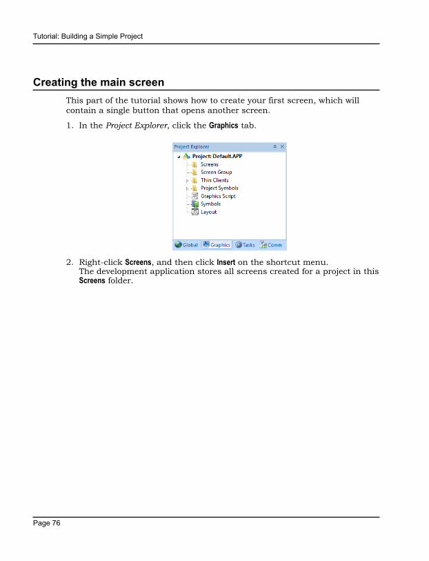
Tutorial: Building a Simple Project
Page 76
Creating the main screenThis part of the tutorial shows how to create your first screen, which willcontain a single button that opens another screen.
1. In the Project Explorer, click the Graphics tab.
2. Right-click Screens, and then click Insert on the shortcut menu.The development application stores all screens created for a project in thisScreens folder.

Tutorial: Building a Simple Project
Page 77
The Screen Attributes dialog is displayed.
Screen Attributes dialog3. Use this dialog to set screen properties such as size and type.
For this tutorial, click OK to accept the default settings.The Screen Attributes dialog is closed, and the new screen is opened in theworkspace for editing.
4. On the Graphics tab of the ribbon, in the Screen group, click Background Color.A standard color picker is displayed.
5. In the color picker, select a light gray color.
Color picker
That color is applied to the screen.

Tutorial: Building a Simple Project
Page 78
Drawing the main screen's titleThis part of the tutorial shows how to draw the main screen's title using aText object.
1. On the Graphics tab of the ribbon, in the Active Objects group, click Text.Your mouse cursor changes from an arrow to a crosshair.
2. Click on the screen, type Welcome to the Tutorial Application, andthen press Return.This creates a new Text object with the specified text.
3. Double-click the object to open its Object Properties dialog.
Object Properties: Text dialog
• Double-clicking on any screen object opens an Object Properties dialogcontaining the properties for that object. The properties shown in thedialog change depending on the type of object.
• The Object Properties dialog also contains a pin button that controlswhether this dialog remains open. The button changes state (andfunction) each time you click on it, as follows:
• When the pin button is released, the focus is passed to the objecton the screen as soon as it is selected. It is recommended that thisbutton is kept released when you want to manipulate the objects(Copy, Paste, Cut, or Delete). Although the Object Properties dialogis on the top, the keyboard commands (Ctrl+C, Ctrl+V, Ctrl+X, or Del)are sent directly to the objects.
• When the pin button is pressed, the focus is kept on the ObjectProperties dialog, even when you click the objects on the screen.We recommend you keep this button pressed when you want tomodify the settings of the objects. You can click an object and typethe new property value directly in the Object Properties dialog (itis not necessary to click on the window to bring focus to it). Also,when the pin button is pressed, the Object Properties dialog doesnot automatically close when you click on the screen.

Tutorial: Building a Simple Project
Page 79
4. Click Fonts to open Font dialog, and then specify the font settings.For this tutorial…
• Font is Arial• Font style is Regular• Size is 20• Color is Blue
Specifying the font settings5. Click OK to close the Font dialog.
The font settings are applied to the Text object.
Font settings applied to Text object

Tutorial: Building a Simple Project
Page 80
6. Close the Object Properties dialog (i.e., click the Close button in the dialogbox's top-right corner).
Drawing a button to open another screenThis part of the tutorial shows how to draw and configure a button that willopen another screen.
1. On the Graphics tab of the ribbon, in the Active Objects group, click Button.Your mouse cursor changes from an arrow to a crosshair.
2. Click and hold on the screen, and then drag the cursor to draw theButton object.
3. Double-click the object to open its Object Properties dialog.
4. In the Caption box, type the following text: Click here to open thesynoptic screen.
Adding a caption to the button5. Click Command.
The Object Properties dialog changes to show the properties for theCommand animation.
6. In the Type list, select Open Screen.

Tutorial: Building a Simple Project
Page 81
7. In the Open Screen box, type synoptic.scc.
Configuring an Open Screen command on the button
You can specify a screen that you have not yet created.
8. Close the Object Properties dialog.
Saving and closing the main screenThis part of the tutorial shows how to properly save and close a screen.
1. Click the Application button at the top-left of the developmentenvironment, and then click Save on the Application menu.A standard Windows Save dialog is displayed.
2. In the File name box, type main.
3. Click Save.The file is saved in your project folder (at <project name>\Screen\main.scc), and the Save dialog is closed.
4. Click the Application button at the top-left of the developmentenvironment, and then click Close on the Application menu.

Tutorial: Building a Simple Project
Page 82
Creating the synoptic screenThis part of the tutorial show how to create your second screen, which willinclude an animated tank of liquid and some basic controls for that tank.
1. In the Graphics tab of the Project Explorer, right-click the Screens folder, andthen click Insert on the shortcut menu.The Screen Attributes dialog is displayed.
2. Use this dialog to set attributes such as size and type.For this tutorial, click OK to accept the default settings.
3. Click the Application button at the top-left of the developmentenvironment, and then click Save As on the Application menu.A standard Windows Save As dialog is displayed.
4. In the File name box, type synoptic.
5. Click Save.The file is saved in your project folder (at <project name:gt;\Screen\synoptic.scc), and the Save dialog is closed.
Do not close the screen like you did the main screen when you saved it. Youstill need to draw the synoptic screen.
Drawing the synoptic screen's titleAs in a previous part, this part of the tutorial shows how to draw the synopticscreen's title using a Text object.
1. On the Graphics tab of the ribbon, in the Active Objects group, click Text.2. Click on the screen, type Synoptic Screen, and then press Return.
3. Double-click the object to open its Object Properties dialog.
4. Click Fonts to open Font dialog, and then specify the font settings.For this tutorial…
• Font is Arial• Font style is Bold• Size is 20• Color is Blue
5. Click OK to save the font settings and close the dialog.
6. Close the Object Properties dialog.
7. Move the Text object to the top left corner of the screen.

Tutorial: Building a Simple Project
Page 83
8. Click the Application button at the top-left of the developmentenvironment, and then click Save on the Application menu.
This figure shows how your screen should look after you have drawn thescreen title.
Finished screen title
Drawing "Date" and "Time" displaysThis part of the tutorial shows how to draw "Date" and "Time" displays bylinking Text objects to system tags.
Date and Time are system tags that hold the current date and time of thelocal station. These tags are available to any project.
1. On the Graphics tab of the ribbon, in the Active Objects group, click Text.2. Click on the screen, type Date: ##########, and then press Return.
3. Double-click the object to open its Object Properties dialog.
4. Click Text Data Link.The Object Properties dialog changes to show the properties for the TextData Link animation.
5. In the Tag/Expression box, type Date.
Specifying the Date system tag
During runtime, the project replaces the ########## characters of theText object with the value of the system tag Date.
6. Close the Object Properties dialog.
7. On the Graphics tab of the ribbon, in the Active Objects group, click Text.

Tutorial: Building a Simple Project
Page 84
8. Click on the screen, type Time: ##########, and then press Return.
9. Double-click the object to open its Object Properties dialog.
10.Click Text Data Link.The Object Properties dialog changes to show the properties for the TextData Link animation.
11.In the Tag/Expression box, type Time.
Specifying the Time system tag
During runtime, the project replaces the ########## characters of theText object with the value of the system tag Time.
12.Close the Object Properties dialog.
13.Click the Application button at the top-left of the developmentenvironment, and then click Save on the Application menu.
This figure shows how your screen should look after you have created thedate and time objects.
Finished date and time objects
Placing an "Exit" iconThis part of the tutorial shows how to place an icon (by selecting andconfiguring a Linked Symbol) that allows the user to exit the project, .
1. On the Graphics tab of the ribbon, in the Libraries group, click Symbols.The symbols library is displayed.
2. In the Symbols menu tree, open the System Symbols folder and then openthe Icons sub-folder.

Tutorial: Building a Simple Project
Page 85
3. In the Icons sub-folder, select exit01.The symbol will be displayed in the symbol viewer to the right of the menutree.
Selecting the "exit01" symbol4. Click on the symbol.
The mouse cursor will change to show that the symbol is ready to beplaced in a screen.
5. Switch back to the screen where you want to place the symbol and thenclick in it.The symbol is placed as a Linked Symbol object.
Placing the Linked Symbol object6. With the object still selected, click Command (on the Graphics tab of the
ribbon, in the Animations group) to apply this animation to the object.
7. Double-click the object to open its Object Properties dialog.
8. In the Type list, select VBScript.9. In the On Down box, type $Shutdown().

Tutorial: Building a Simple Project
Page 86
Shutdown is one of InduSoft Web Studio's built-in scripting functions, butit can be used within VBScript by prefacing it with a dollar sign ($).
Specifying the Shutdown command on the symbol10.Close the Object Properties dialog.
11.Click the Application button at the top-left of the developmentenvironment, and then click Save on the Application menu.
Now, when a user clicks this icon during runtime, the project will stop andexit to the station's desktop.
Testing the projectThis part of the tutorial shows how to test the project so far.
1. Click the Application button at the top-left of the developmentenvironment, and then click Close > Close All on the Application menu.All open worksheets are closed.
2. On the Home tab of the ribbon, in the Local Management group, click Run.The project runs and the startup screen is displayed.
3. Click the button to open the synoptic screen.The synoptic screen is displayed.
4. Click the exit icon to shut down the project.
If any part of the project does not work as expected, switch back to thedevelopment application (ALT+TAB) and then click Stop on the Home tab of theribbon.
Placing an animated tankThis part of the tutorial shows how to select an animated tank from theSymbol Library and place it on the screen (similar to how you selected andplaced the "Exit" icon), then associate some project tags with the tank'sproperties.
1. In the Graphics tab of the Project Explorer, expand the Screens folder.

Tutorial: Building a Simple Project
Page 87
2. Double-click synoptic.scc.The synoptic screen worksheet is reopened for editing.
3. On the Graphics tab of the ribbon, in the Libraries group, click Symbols.
4. In the Symbols menu tree, open the System Symbols folder and then openthe Tanks sub-folder.
5. Browse the tank symbols and choose one.You may choose any tank symbol that you like; they all function basicallythe same.
Choosing a tank symbol6. Click the symbol.
The mouse cursor will change to show that the symbol is ready to beplaced in a screen.
7. Switch back to the screen where you want to place the symbol and clickin it.The symbol is placed as a Linked Symbol object.
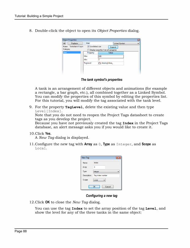
Tutorial: Building a Simple Project
Page 88
8. Double-click the object to open its Object Properties dialog.
The tank symbol's properties
A tank is an arrangement of different objects and animations (for examplea rectangle, a bar graph, etc.), all combined together as a Linked Symbol.You can modify the properties of this symbol by editing the properties list.For this tutorial, you will modify the tag associated with the tank level.
9. For the property TagLevel, delete the existing value and then typeLevel[Index].Note that you do not need to reopen the Project Tags datasheet to createtags as you develop the project.Because you have not previously created the tag Index in the Project Tagsdatabase, an alert message asks you if you would like to create it.
10.Click Yes.A New Tag dialog is displayed.
11.Configure the new tag with Array as 0, Type as Integer, and Scope asLocal.
Configuring a new tag12.Click OK to close the New Tag dialog.
You can use the tag Index to set the array position of the tag Level, andshow the level for any of the three tanks in the same object:

Tutorial: Building a Simple Project
Page 89
• When Index equals 1, the tank object shows the level of Tank #1 (i.e.,Level[1]);
• When Index equals 2, the tank object shows the level of Tank #2 (i.e.,Level[2]); and
• When Index equals 3, the tank object shows the level of Tank #3 (i.e.,Level[3]).
Also, because the tag scope is local, the tag can have different values forthe Server and Client stations at the same time. Consequently, the localuser (i.e., the Server station) can be monitoring the level of Tank #1 whilethe remote user (i.e., the Client station) is monitoring the level of Tank #2.
13.Close the Object Properties dialog.
14.Click the Application button at the top-left of the developmentenvironment, and then click Save on the Application menu.
This figure shows how your screen should look after you've created the tankobject.
Finished tank object
Placing a level sliderThis part of the tutorial shows how to select a slider control from the SymbolLibrary and then connect it to the animated tank.
1. On the Graphics tab of the ribbon, in the Libraries group, click Symbols.

Tutorial: Building a Simple Project
Page 90
2. In the Symbols menu tree, open the System Symbols folder and then openthe Sliders sub-folder.
Selecting a slider symbol3. In the Sliders sub-folder, select a slider control.
You may select any slider you like; they all function basically the sameway.
4. Click on the symbol.The mouse cursor will change to show that the symbol is ready to beplaced in a screen.
5. Switch back to the screen where you want to place the symbol and clickin it.The symbol is placed as a Linked Symbol object.
6. Double-click the object to open its Object Properties dialog.
7. For the property TagName, delete the existing value and then typeLevel[Index].Just as with the tank, you need to modify the symbol property associatedwith the slider level.
8. Close the Object Properties dialog.
9. Click the Application button at the top-left of the developmentenvironment, and then click Save on the Application menu.

Tutorial: Building a Simple Project
Page 91
This figure shows how your screen should look after you've created the levelslider object.
Finished level slider object
Drawing a tank selectorThis part of the tutorial shows how to draw a text input box that can be usedto change which real-world tank is represented by the animated tank on thescreen.
1. On the Graphics tab of the ribbon, in the Active Objects group, click Text.2. Click on the screen, type Tank: #, and then press Return.
3. Double-click the object to open its Object Properties dialog.
4. Click Text Data Link.The Object Properties dialog changes to show the properties for the TextData Link animation.
5. In the Tag/Expression box, type Index.
6. Select the Input Enabled option.This allows the operator to enter a new value for the tag during runtime.
7. In the Minimum Value box, type 1.
8. In the Maximum Value box, type 3.
Configuring the "Tank" text input

Tutorial: Building a Simple Project
Page 92
9. Close the Object Properties dialog.
10.Click the Application button at the top-left of the developmentenvironment, and then click Save on the Application menu.
This figure shows how your screen should look after you've created the tankselector object.
Finished tank selector object during runtime
Testing the projectThis part of the tutorial shows how to test the project again with theanimated tank, the level slider, and the tank selector.
1. Click the Application button at the top-left of the developmentenvironment, and then click Close > Close All on the Application menu.All open worksheets are closed.
2. On the Home tab of the ribbon, in the Local Management group, click Run.The project runs and the startup screen is displayed.
3. Click the button to open the synoptic screen.The synoptic screen is displayed.
4. Type the tank number (1, 2, or 3) in the Tank label, and then use theslider to adjust the tank level.Note that you can view/adjust the level of each tank independently.
5. Click the exit icon to shut down the project.
If any part of the project does not work as expected, switch back to thedevelopment application (ALT+TAB) and then click Stop on the Home tab of theribbon.

Tutorial: Building a Simple Project
Page 93
Configuring the communication driverThis part of the tutorial shows how to select and configure a driver tocommunicate with an external I/O device.
1. In the Project Explorer, click the Comm tab.
2. Right-click the Drivers folder, and the click Add/Remove Drivers on theshortcut menu.The Communication Drivers dialog is displayed.
3. Select a driver from the Available drivers list, and then click Select.For this tutorial, select MODBU.The driver is moved to the Selected drivers list.
MODBU driver selected4. Click OK.
The Communication Drivers dialog is closed, and the driver is added to theDrivers folder in the Project Explorer.

Tutorial: Building a Simple Project
Page 94
5. In the Project Explorer, right-click the MODBU folder, and then click Settingson the shortcut menu.
The Communication Settings dialog is displayed.
Communication Settings dialog for MODBU driver6. Configure the communication settings as needed for the target device.
For this tutorial, accept the default settings.
Note: For more information about a specific driver, clickCommunication Drivers on the Help tab of the ribbon.
7. Click OK to close the dialog.
8. In the Project Explorer, right-click the MODBU folder and then click Insert onthe shortcut menu.A new driver worksheet named MODBU001.drv is created and opened forediting.
9. Configure the worksheet header:a) In the Description box, type Tutorial Modbus.
This setting is for documentation only; it does not affect the runtimeproject in any way.
b) In the Enable Read When Idle box, type 1.

Tutorial: Building a Simple Project
Page 95
This setting is a trigger that takes a Boolean value. A value of 1 —either entered manually as above or evaluated from a tag/expression— forces your project to continue reading tag values from the targetdevice even when there are no changes in value.
c) In the Enable Write On Tag Change box, type 1.This setting is also a trigger. A value of 1 forces your project towrite tag values to the target device only when those values change,rather than continuously. This saves system resources and improvesperformance during rutime.
d) In the Station box, type 1.This indicates the I/O device number to be accessed by this driver.Typically, the PLC is specified as Device #1.
e) In the Header box, type 4X:0.
You must use a driver-specific format. The format for the MODBUdriver is:
register_type:initial_offset
Register Type Description
0X Coil Status
1X Input Status
3X Input Register
4X Holding Register
ID Slave ID Number
Completed worksheet header

Tutorial: Building a Simple Project
Page 96
10.In the worksheet body, enter the tags and their associated deviceaddresses — for each tag:a) In the Tag Name field, type the name of the project tag.
b) In the Address field, type the value to be added to the header to form thecomplete device address.
Tag Name Address Complete Device Address
Level[1] 1 4X:1 (Holding Register 1)
Level[2] 2 4X:2 (Holding Register 2)
Level[3] 3 4X:3 (Holding Register 3)
Completed worksheet body11.Click the Application button at the top-left of the development
environment, and then click Save on the Application menu.
12.When prompted to choose the driver sheet number, type 1 and then clickOK.
Monitoring device I/O during runtimeThis part of the tutorial shows how to monitor device I/O during runtime byusing the Log window.
1. On the Home tab of the ribbon, in the Local Management group, click Run.The project runs and the startup screen is displayed.
2. Press ALT+TAB to switch back to the development application.
3. Right-click in the Output window, and then click Settings.The Log Settings dialog is displayed.
4. Select the Field Read Commands, Field Write Commands, and Protocol Analyzeroptions.
5. Click OK to close the Log Settings dialog.

Tutorial: Building a Simple Project
Page 97
You can now monitor the device I/O during runtime.

Tutorial: Building a Simple Project
Page 98
Downloading your project to a Windows Embedded deviceThis part of the tutorial shows how to download your project to a WindowsEmbedded device, such as a plant-floor HMI panel.
After configuring a project and testing it locally (on the development station),you can download it to a remote station — either a Windows PC that isrunning IWS or a Windows Embedded device that is running EmbeddedViewor CEView.
1. On the desktop of the remote station, click Start > All Apps > InduSoft WebStudio v8.1 > IWS v8.1 Remote Agent.The Remote Agent utility runs.
Remote Agent utility2. Click Setup.
The Setup dialog is displayed.
3. Select the type of connection — Serial, TCP/IP, or Infrared — between theremote station and the development station.

Tutorial: Building a Simple Project
Page 99
Note: For better performance, we recommend that you useTCP/IP whenever possible.
Selecting TCP/IP on the remote station4. Click OK to close the Setup dialog, but leave the Remote Agent utility
running on the remote station.
5. In the development application, click Connect on the Home tab of the ribbon.The Remote Management dialog is displayed.
Remote Management dialog6. Select the type of connection to the target (remote) station.
This selection should match the selection you previously made in theRemote Agent utility on the remote station.

Tutorial: Building a Simple Project
Page 100
7. If you selected Host, type the host name or IP address of the remotestation.
8. Click Connect.If you successfully connect to the remote station, then information aboutthat station is displayed in the Status and Platform boxes.
9. If the remote station is a Windows Embedded device, click Install system files.The system files are installed on the remote station.
10.Click the Project tab.
11.Click Download.The project files are downloaded to the remote station.
12.Click Run.Your IWS project is run on the remote station.

Tutorial: Building a Simple Project
Page 101
Deploying your project as a web applicationThis part of the tutorial shows how to deploy your project as a webapplication, to which remote users can connect with Internet Explorer.
For Internet Explorer to work as a web thin client, it must install a browserplug-in that "plays" IWS project screens. If your computer is connected tothe Internet, then IE will automatically download the control from InduSoft'spublic server when you connect to a project runtime server for the first time.
To deploy your project as a web application:
1. Configure the IP address of the data server.a) On the Project tab of the ribbon, in the Web group, click Web.
The Project Settings dialog is displayed with the Web tab selected.
Web tab of Project Settings dialogb) In the Data Server IP Address box, type the IP address of the web server.
For this tutorial, type 127.0.0.1, which is the standard loopbackaddress (a.k.a. "localhost").
c) Click OK to close the dialog.
2. Make sure the data server is set to start up when you run your project.a) On the Home tab of the ribbon, in the Local Management group, click Tasks.

Tutorial: Building a Simple Project
Page 102
The Execution Tasks dialog is displayed.
Execution Tasks dialog

Tutorial: Building a Simple Project
Page 103
b) In the list of tasks, select TCP/IP Server Runtime, and then click Startup.The Startup dialog is displayed.
Startup dialogc) Select Automatic, and then click OK.
d) Click OK to close the Execution Tasks dialog.
3. Save and close all open screens and worksheets.
4. Click the Application button at the top-left of the developmentenvironment, and then click Publish > Save All As HTML on the Applicationmenu.Your project screens are saved as HTML files in the Web sub-folder ofyour project folder (i.e., \<project name>\Web).
5. Configure a web server to make the Web sub-folder available to thenetwork.For this tutorial, use NTWebServer, which is free, lightweight web serverprogram that is included with the InduSoft Web Studio software. Simplycopy it from the InduSoft Web Studio program folder (at InduSoft WebStudio v8.1\Bin\NTWebServer.exe) to your project's Web sub-folder(at <project name>\Web), and then double-click the file to run it. Itautomatically serves the contents of whatever folder it is in, without anyfurther configuration.
Note: NTWebServer is provided for testing purposes only. Itshould never be used in a real production environment or on asecure network.
You can also configure the "root directory" or "home directory" setting ofsome other web server program (e.g., Microsoft IIS) to point to the Websub-folder, or you can copy the Web sub-folder to an existing web serveron your network. The web server (which makes the HTML files availableto clients) and the data server (which actually runs your IWS project andexchanges data with the clients) do not need to be the same computer.
6. On the Home tab of the ribbon, in the Local Management group, click Run.

Tutorial: Building a Simple Project
Page 104
7. Open a web browser (e.g., Microsoft Internet Explorer), and then enter theURL address of the synoptic screen on the web server.For this tutorial, type http://127.0.0.1/synoptic.html and then pressReturn. (127.0.0.1 is the standard IP address for the loopback networkinterface, a.k.a. "localhost".)After a few moments, during which the browser downloads and installsthe browser plug-in, the synoptic screen is displayed in the browser.
Notice that you can change the level of any tank either locally using theproject viewer or remotely using the web browser, and changes on one clientappear immediately on the other. They work equally well.