Quick start guide for p5 510 (9110-51A) - IBM · 2016-05-07 · Quick start guide for p5 510 ......
16
Quick start guide for p5 510 (9110-51A) IBM Systems
Transcript of Quick start guide for p5 510 (9110-51A) - IBM · 2016-05-07 · Quick start guide for p5 510 ......

Quick start guide for p5 510 (9110-51A)
IBM Systems

1 Before you begin
This Quick start guide contains an abbreviated set of setup instructions designed to help you quicklyunpack and set up a standard system. Users unfamiliar with this IBM hardware should use the fullydetailed, setup instructions that you can find in the IBM Systems Hardware Information Center. Fordetails about how to access the information center, see task 9 .Finish your system setup
CAUTION: The weight for this part or unit is between 18 and 32 kg (39.7 and70.5 lbs). It takes two persons to safely lift this part or unit. (C009)
The exclamation mark surrounded by a gray triangle denotes caution. A CAUTIONnotice indicates the presence of a hazard that has the potential of causingmoderate or minor personal injury. Before doing a step that contains a caution icon,read and understand the caution statement that accompanies it.
Use safe practices when lifting.
Rack-mounted devices are not to be used as a shelf or workspace. Do notplace any object on top of rack-mounted devices.
18-32 kg (39.7-70.5 lbs)
Tools needed (Rack installation only)
Flat-blade screwdriver

Inventory22.1 Complete an inventory of the external parts.
Locate the kitting report (inventory list) in the bag that contains the informationcenter CD (SK3T-8159). Make sure you received all of the parts that you ordered.Your order information should be located in an envelope adhered to the outsideof your system box. You can also obtain order information from your marketingrepresentative or IBM Business Partner.
If you have incorrect, missing, or damaged parts, consult any of the followingresources:
Your IBM resellerIBM Rochester manufacturing automated informationline at 1-800-300-8751 (United States only)Directory of worldwide contacts at www.ibm.com/planetwide.Select your location to view the service and support contact information.
2.2 You will need the following parts:
Slide rail assemblies
Cable-management arm
Rack-mounting hardware kit
Screws2
33.1
3.2
3.3
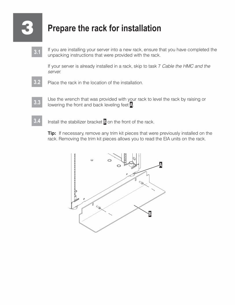
If you are installing your server into a new rack, ensure that you have completed theunpacking instructions that were provided with the rack.
If your s is already installed in a rack, skip to task 7
Place the rack in the location of the installation.
Use the wrench that was provided with your rack to level the rack by raising orlowering the front and back leveling feet .
Install the stabilizer bracket on the front of the rack.
If necessary, remove any trim kit pieces that were previously installed on therack. Removing the trim kit pieces allows you to read the EIA units on the rack.
A
B
Tip:
erver Cable the HMC and theserver.
3.4
Prepare the rack for installation
A
B

4.1Determine where in the rack to place the server. This server occupies two EIA units.Remove any filler panels necessary to allow adequate access to the location whereyou will install your server.
If you do not have enough space around your rack to open the front and back doorscompletely, remove the doors before starting this task to allow adequate access.
Install the slide rail assemblies4
4.2Install the slide rail assemblies.
A B
C
D D
C
Pull the front and back blue latch-assembly release tabs and use the bluetabs to push the latch assembly into the retracted position. Make sure bothfront and back slide-rail pins are fully retracted.
B CD
A1.
Front view
Note: Install units into the lower part of the rack first. Place larger and heavierunits in the lower part of the rack.
A
B
Back view
4.3
4.4
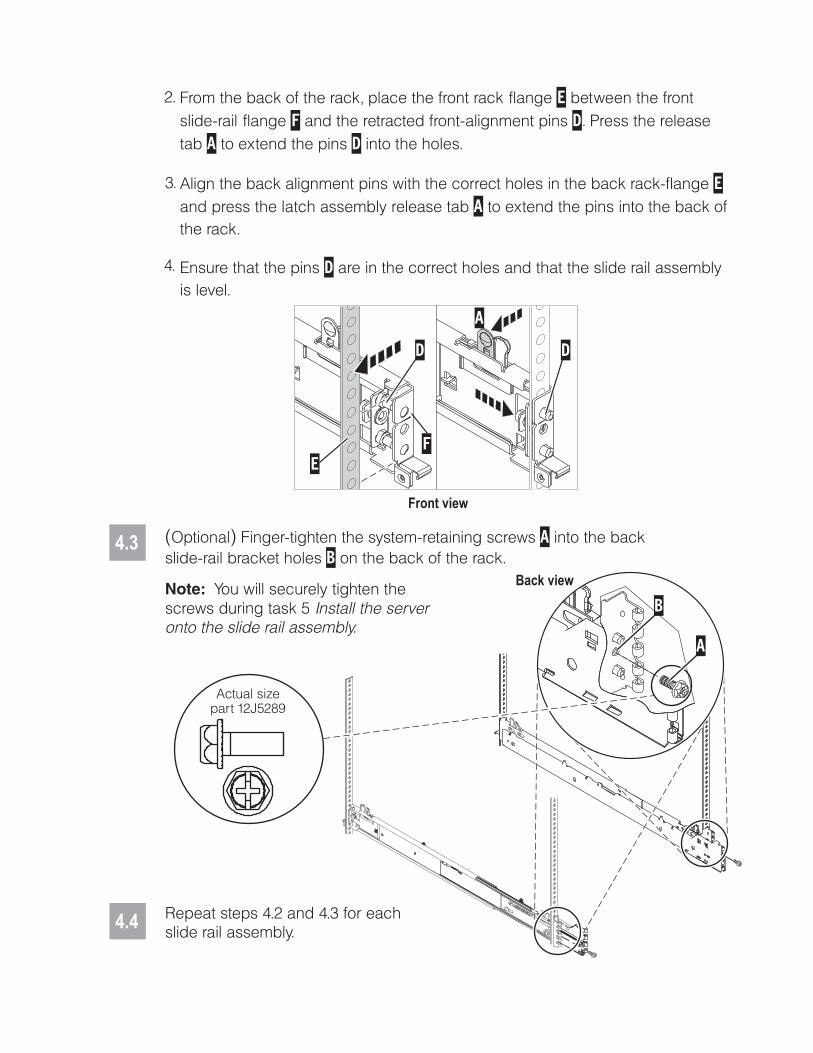
( )Optional Finger-tighten the system-retaining screws into the backslide-rail bracket holes on the back of the rack.
AB
Repeat steps 4.2 and 4.3 for eachslide rail assembly.
Note: You will securely tighten thescrews during task 5 Install the serveronto the slide rail assembly.
From the back of the rack, place the front rack flange between the frontslide-rail flange and the retracted front-alignment pins . Press the releasetab to extend the pins into the holes.
Align the back alignment pins with the correct holes in the back rack-flangeand press the latch assembly release tab to extend the pins into the back ofthe rack.
Ensure that the pins are in the correct holes and that the slide rail assemblyis level.
EF D
A D
EA
D
2.
3.
4.
A
E
DD
F
Front view
Actual sizepart 12J5289

5
5.1
5.3
5.4
5.5
5.2
5.6
Fully extend both slide rails.
Lift the server, and position it over the extended slide rails.
Use a screwdriver to tighten the system-retaining screws that you may haveinstalled in step 4.3.
Use safe practices when lifting.
Align the slots on the server chassis with the tabs on the slide rails.B A
Lower the server onto the slide rails, ensuring that the slots and tabs aligncorrectly, and the server is securely seated onto the slide rails.
B A
Simultaneously pull the blue safety latches on the slide rails of each side of theserver, and carefully push the server into the rack.
C
C
BB
A
A
Install the server onto the slide rail assembly
Before you begin: Read this entire task before completing any individual steps.
Before installing the server onto the slide rail assembly, ensure that theleveling feet are extended and that the stabilizer bracket is correctly installedto prevent the rack from falling forward.
18-32 kg (39.7-70.5 lbs)

6.1 Locate the cable-management arm and the two pins .E A
6 Install the cable-management arm
6.3
From the back of the rack, use the pin to affix the cable-management arm tothe left slide-rail management arm flange that is attached to the rack frame .
A ED-6.2
Use the second pin to affix the other end of the cable-management arm to theflange that is attached to the sliding portion of the left slide rail assembly .
AC B
E
Tip: If space is limited inside the rack, slide the server out part of the way to installthe cable-management arm.
A
B
C
D
E

7.1
7.2
7.3
Route the power cords through the rings or clamps, if available, andconnect to the server, monitor, and HMC. Do not connect the powercords to a power source until instructed to do so.
Important: Ensure that if there is a voltage switch next to the powerconnector on the monitor, it is in the appropriate position for the voltageused in your geography.
7.4Attach the monitor cable to the monitor connector on the HMC andtighten the screws.
Tip: If you are using the rack-mounted LCD monitor and keyboard (7316-TF3),use the C2T-to-KVM adapter breakout cable to attach to the HMC.
A Hardware Management Console (HMC) is a system that connects to the server and manages itthrough a network.
If you are using a rack-mounted HMC, these steps assume that it is already installed in the rack.
If you need to install the HMC into the rack, follow the instructions in the IBM Systems HardwareInformation Center, and return to this guide when you are ready to begin cabling your HMC. For detailsabout how to access the information center, see task 9
If you are not using an HMC to manage your server, you can use the IntegratedVirtualization Manager (IVM), a graphics terminal, or an ASCII terminal. If you plan to useIVM, which allows you to create and manage partitions, skip to task 8
. For information about the other consoleoptions, go to the IBM Systems Hardware Information Center. For details about how toaccess the information center, see task 9 .
Cable the server andaccess the Integrated Virtualization Manager
Finish your system setup
Finish your system setup.
If you are using any optional adapters for the HMC, connect the cables to theappropriate adapter connectors in the PCI slots of your server and HMC.
Cable the HMC and the server7
Connect the mouse and keyboard cables to the appropriate ports on the backof the HMC. If your mouse and keyboard use Universal Serial Bus (USB)cables, you can connect these to the ports on the front of the HMC.

7.5
7.6
If you are not using a modem, skip to step 7.6.
If you are using the integrated HMC modem, connect the telephone cable to themodem and to the analog jack on the wall. If you are using an external modem,connect the modem data cable to the external modem and to a serial port onthe HMC. Then connect the telephone cable to the external modem and to theanalog jack on the wall.
Connect the Ethernet cable to the Ethernet port on the HMC and tothe Ethernet port labeled HMC1 on the server.
For a stand-alone HMC, use the integrated Ethernet port. For the 7310-CR2 rack-mounted HMC, use the bottom-right Ethernet port. For the 7310-CR3 rack-mounted HMC, use the left port of the two planar board Ethernet ports.
7.7
7.8
CAUTION: This product is equipped with a 3-wire (two conductors and aground) power cable and plug. Use this power cable with a properlygrounded electrical outlet to avoid electrical shock. (C018)
Plug the power cords for the monitor, HMC, and external modem into a powersource. Do not connect the server to a power source until instructed to do so.
You have completed the basic setup. Go to task 9 Finish your system setup.
Route the cables through the cable-management arm on the server, andsecure the cables with the straps provided.
If using an external modem, plug the power cord into the modem.
7.9
Start and configure the HMC, which includes the Guided Setup Wizard. You canfind the instructions for configuring the HMC in the IBM Systems HardwareInformation Center. For details about how to access the information center, seetask 9 Finish your system setup.
7.10
Connect the s to a power source and wait for the control panel on the frontof the server to display . This might take several minutes.
erver ,01
7.11
Press the white Power On button on the control panel.7.12

8.1
8.2
Connect one end of a serial cable to the system port on your server, and the otherend to a serial port on a PC that has Microsoft Internet Explorer 6.0, Netscape 7.1, orOpera 7.23 installed.
8
Connect an Ethernet cable from the PC to the port labeled HMC1 on the back ofthe server. If HMC1 is occupied, use the port labeled HMC2.
If you are using any optional adapters, connect the cables to the appropriateadapter connectors in the PCI slots of your server and PC.
Cable the server and access the IntegratedVirtualization Manager
CAUTION: This product is equipped with a 3-wire (two conductors and aground) power cable and plug. Use this power cable with a properlygrounded electrical outlet to avoid electrical shock. (C018)
Route the power cords through the rings or clamps, if available, on the back of theserver, and connect the server to a power source. Wait for the control panel on thefront of the server to display . This might take several minutes.01
8.3
8.4

8.8
8.6
At the login prompt, enter the following default user ID and password:
In the navigation area, expand .
Click .
Select in the Boot to system server firmware field.
Click .
Power/Restart Control
Power On/Off System
Standby
Save settings and power on
User IDadmin
Passwordadmin
Configure the Ethernet interface on the PC to an IP address and subnet maskwithin the same subnet as the server. This is the IP address for the serviceprocessor.
Server connectorHMC1HMC2
Subnet mask255.255.255.0255.255.255.0
IP address192.168.2.147192.168.3.147
For example, if you connected your PC to HMC1, the IP address for your serviceprocessor might be 192.168.2.1 and the subnet mask would be 255.255.255.0. Setthe gateway IP address to the same IP address as that of the PC.
Using a Web browser, enter the IP address into the field that correspondsto the port to which your PC is connected. For example, enter https://192.168.2.147.
Address
Possible values:
Note: If you do not know how to do this, see the instructions in the IBM SystemsHardware Information Center. For details about how to access the informationcenter, see task 9 Finish your system setup.
When you are prompted, change the default password.
8.7
8.10
8.9
1.
2.
3.
4.
Change the state of the system server firmware.
8.5Route the cables through the cable-management arm and secure the cables tothe cable-management arm.

8.12
Open a terminal session on the PC, using an application such asHyperTerminal. Be sure the line speed is set to 19,200 bits per second tocommunicate with the system.
8.15
Change the partition mode.
Insert the Virtual I/O Server CD into the optical drive of the system.
1.
2.
3.
4.
5.
In the navigation area, expand .
Click .
Select in the AIX/Linux partition mode boot field.
Select in the Boot to system server firmware field.
Click .
Power/Restart Control
Power On/Off System
Boot to SMS menu
Running
Save settings and continue system server firmware boot
8.13
1.
2.
3.
4.
In the ASMI navigation area, expand .
Click .
Select in the AIX/Linux partition mode boot field.
Click .
Power/Restart Control
Power On/Off System
Continue to operating system
Save settings
8.14Change the partition mode back so that the server continues to load the operatingsystem during startup.
8.11After the system has reached the firmware standby state, enter the activationcode for the Virtualization Engine technologies.TM
In the navigation area, expand .
Click .
Enter the activation key into the field. This key was included with the printedmaterial inside your system box.
Click . The Advanced POWER Virtualization feature is enabled.
On Demand Utilities
CoD Activation
Continue
1.
2.
3.
4.
1.
2.
3.
4.
Select the console, and press Enter.
Select a language for the BOS menus, and press Enter.
Select .
Select . The managed system restarts after theinstallation is complete, and the login prompt is displayed on the ASCIIterminal.
Start Install Now with Default Settings
Continue with Install
8.17 Install the Virtual I/O Server.
8.16When the system management services (SMS) menu is displayed in theterminal session over the connection that you set up in step 8.1, choose
and follow the menu options to set the optical drive asthe initial boot device.Select Boot Options
Tip: Additional Information about the Virtual I/O Server, such as how to check forupdates, configure network connections, and configure partitions, is located in theIBM Systems Hardware Information Center.
You have completed the basic setup. Continue to task 9 Finish your system setup.

Finish your system setup9
Using a Web browser, go to www.ibm.com/systems/infocenter/hardware or go tothe preinstalled version on the HMC.
Answer the questions in the interactive interview, and follow the procedures in theresulting checklist.
From the navigation bar, click Systems Hardware information System pInformation Initial server setup Create a customized initial server setupchecklist.
>> >
You have completed the basic tasks to set up your server.
You can access the . Follow these steps to create acustomized checklist that helps you configure your server and console, install software, apply fixes, andestablish connections with your service provider:
now IBM Systems Hardware Information Center
If you cannot access the online version of the information center, it is also provided ona CD with your system (SK3T-8159).
9.1
9.2
9.3

International Business Machines Corporation 2006, 2007
Printed in USASeptember 2007All Rights Reserved
Mail comments to:IBM CorporationAttention Department DDR3605 Highway 52 NorthRochester, MN U.S.A. 55901-7829
Fax comments to:1-800-937-3430 (U.S. or Canada)1-507-253-5192 (outside the U.S. or Canada)Internet URL: http://www.ibm.com/systems/infocenter/hardware
References in this publication to IBM products orservices do not imply that IBM intends to makethem available in every country or region.
IBM, the IBM logo, and System p are trademarks ofInternational Business Machines Corporation
Other company, product, and service names maybe trademarks or service marks of others.
in theUnited States, other countries or both.
Microsoft, Windows, Windows NT, and the Windowslogo are trademarks of Microsoft Corporation inthe United States, other countries, or both.
SA41-5172-03
29R1718