Quick start guide for FRDM-KEA - NXP Semiconductors USE Ultra-Reliable MCUs for Industrial and...
26
EXTERNAL USE Ultra-Reliable MCUs for Industrial and Automotive Applications www.nxp.com/FRDM-KEA FRDM-KEA QUICK START GUIDE (QSG) FRDM-KEAZ128 FRDM-KEAZ64 FRDM-KEAZN32
Transcript of Quick start guide for FRDM-KEA - NXP Semiconductors USE Ultra-Reliable MCUs for Industrial and...

EXTERNAL USE
Ultra-Reliable MCUs for Industrial and Automotive Applications
www.nxp.com/FRDM-KEA
FRDM-KEA
QUICK START GUIDE (QSG)FRDM-KEAZ128
FRDM-KEAZ64
FRDM-KEAZN32

EXTERNAL USE1
Contents
• Quick Start Package Overview
• Get to know the FRDM-KEAZ128
• Hardware: FRDM-KEA Board
− Features
− Pinout and Jumper Settings
• Out of the Box Setup using S32 Design Studio
• Out of the Box Setup using KDS
• Software
• Documentation
• KEA Family : Phantom Feature Differences
• OpenSDA
• Recommendations
EXTERNAL USE2
Quick Start Package Overview
Name Type Description
Quick Start Guide PDF This document
Precompiled Examples Folder S-record images of example projects for use with the MSD Flash
SDK Evaluation Drivers Folder Headers and source code drivers, driver summary and testing
Additional reference documents are available on www.nxp.com/FRDM-KEA
Name Description
FRDM-KEA Quick Start Package Quick Start Guide and supporting files for getting started with the FRDM-KEA
FRDM-KEA User’s Guide This document— Overview and detailed information for the FRDM-KEA hardware
FRDM-KEA Pinouts Spreadsheet of pin connections for all MCU pins. Includes pinout for the I/O headers,
Arduino™ R3 compatibility chart, and OpenSDA MCU pinout.
FRDM-KEA Schematics PDF and Gerber schematic files for the FRDM-KEA hardware
FRDM-KEA Design Package Zip file containing all design source files for the FRDM-KEA hardware
OpenSDA User’s Guide Overview and instructions for use of the OpenSDA embedded debug circuit

EXTERNAL USE3
External Power Supply (5-12V)
CAN Communication Bus
System Basis Chip MCZ33903
RGB LED
S9KEAZ128 MCU
LIN Communication Bus
OpenSDA USB
Reset Button
OpenSDA MCU
OpenSDA JTAG
Potentiometer
User Buttons
Get to know the FRDM-KEAZ128
J2 Header
J1 Header
J6 Header
J3 Header
J4 Header
J5 Header

EXTERNAL USE4
FRDM-KEA Board : Features
• Supports KEAZ128, KEAZ64 and KEAZN32 MCUs
• KEA is 5V, qualified to Automotive Grade 1 and -40 to +125 °C
• • Small form factor size supports up to 6” x 4”
• Platform supports scalability up to 176 pins
• • Arduino™ UNO footprint-compatible with expansion “shield” support
• • Integrated open-standard serial and debug adapter (OpenSDA) with
support for several industry-standard debug interfaces
• • Easy access to the MCU I/O header pins for prototyping
• • On-chip connectivity for CAN, LIN, UART/SCI and SPI
• • Potentiometer for precise voltage and analog measurement
• • RGB LED
• • Two push-button switches (SW2 and SW3)
• Flexible power supply options
• microUSB or
• external 12V power supply
• Similar hardware across ARM®, S12 and Power Architecture®
architecture based MCUs
• Includes:
• Freescale Freedom board
• URL to online Quick Start Guide (QSG)
• Complimentary IDE Software
• KDS and S32 Design Studio

EXTERNAL USE5
Header/Pinout Mapping for FRDM-KEAZ128
PIN PORT FUNCTION J3 PIN PORT FUNCTION
J3-01 VIN J3-02 PTB6* GPIO
J3-03 IOREF J3-04 PTB7* GPIO
J3-05 PTA5
RESET_
TGTMCU J3-06 PTE0 GPIO
J3-07 P3V3 J3-08 PTE1 GPIO
J3-09 5V J3-10 PTE2 GPIO
J3-11 GND J3-12 PTE3 GPIO
J3-13 GND J3-14 PTE4 GPIO
J3-15 VIN J3-16 PTE5 GPIO
PIN PORT FUNCTION J4 PIN PORT FUNCTION
J4-01 PTC0 ADC0 J4-02 PTF1 GPIO
J4-03 PTC1 ADC1 J4-04 PTC4 GPIO
J4-05 PTF4 ADC2 J4-06 PTC5 GPIO
J4-07 PTF5 ADC3 J4-08 PTE6 GPIO
J4-09 PTF6 ADC4 J4-10 PTH0 GPIO
J4-11 PTF7 ADC5 J4-12 PTE7 GPIO
J4-13 PTA0 ADC6 J4-14 PTH6 GPIO
J4-15 PTA1 ADC7 J4-16 PTH7 GPIO
PIN PORT FUNCTION J5 PIN PORT FUNCTION
J5-01 PTC2 ADC8 J5-02 PTF2 GPIO
J5-03 PTC3 ADC9 J5-04 PTF3 GPIO
J5-05 PTB3 ADC10 J5-06 PTI2 GPIO
J5-07 PTA6 ADC11 J5-08 PTI3 GPIO
J5-09 PTA7 ADC12 J5-10 VDD
J5-11 PTB0 ADC13 J5-12 GND
J5-13 PTB1 ADC14 J5-14 PTI4 GPIO
J5-15 PTB2 ADC15 J5-16 PTI5 GPIO
J5-17 NC J5-18 PTI6 GPIO
J5-19 SBC_SAFE J5-20 PTH5 GPIO* For pin multiplex options
please review pinmap file
PIN PORT FUNCTION J2 PIN PORT FUNCTION
J2-19 PTA3 D15 J2-20 PTG3 GPIO
J2-17 PTA2 D14 J2-18 PTG2 GPIO
J2-15 A REF J2-16 PTG1 GPIO
J2-13 GND J2-14 PTG0 GPIO
J2-11 PTB2 D13 J2-12 PTF0 GPIO
J2-09 PTB4 D12 J2-10 PTH1 GPIO
J2-07 PTB3 D11 J2-08 PTC2 GPIO
J2-05 PTB5 D10 J2-06 PTC3 GPIO
J2-03 PTH2 D9 J2-04 PTB4 GPIO
J2-01 PTC5 D8 J2-02 PTB5 GPIO
PIN PORT FUNCTION J1 PIN PORT FUNCTION
J1-15 PTG7 D7 J1-16 PTA4 GPIO
J1-13 PTG6 D6 J1-14 PTA1 GPIO
J1-11 PTG5 D5 J1-12 PTD7 GPIO
J1-09 PTG4 D4 J1-10 PTD6 GPIO
J1-07 PTH1 D3 J1-08 PTD5 GPIO
J1-05 PTF0 D2 J1-06 PTD4 GPIO
J1-03 PTB1 D1 J1-04 PTD3 GPIO
J1-01 PTB0 D0 J1-02 PTD2 GPIO
PIN PORT FUNCTION J6 PIN PORT FUNCTION
J6-19 PTC7 D14 J6-20 NC
J6-17 PTC6 D15 J6-18 NC
J6-15 PTI1 D16 J6-16 NC
J6-13 PTI0 D17 J6-14 NC
J6-11 PTF3 D18 J6-12 GND
J6-09 PTF2 D19 J6-10 VDD
J6-07 PTH3 D20 J6-08 PTH2 GPIO
J6-05 PTH4 D21 J6-06 PTE7 GPIO
J6-03 PTD1 GPIO J6-04 PTD3 GPIO
J6-01 PTD0 GPIO J6-02 PTD2 GPIO

EXTERNAL USE6
FRDM-KEA: Jumper Settings
There is only one jumper: J104
It is to select Reset source:
1-2: Default
2-3: Reset signal direct to the MCU
when OpenSDA is not powered

EXTERNAL USE7
Package Level Pinout Diagram – KEAZ128 (80 LQFP)

EXTERNAL USE8
Package Level Pinout Diagram – KEAZ64 (64 LQFP)

EXTERNAL USE9
Package Level Pinout Diagram – KEAZN32 (64 LQFP)

EXTERNAL USE10
Step-by-Step Setup Instructions for S32 Design Studio IDE
1
Install Software and Tools
Install S32 Design Studio for ARM MCUs V1.x at
S32 Design Studio for ARM v2.0 for Windows
Download the Software Installation Guide for S32DS which provides step by step
installation instructions
2
Power up FRDM-KEA Board
Follow step by step power and setup procedures on slides 12-14
3
Run the Pre-loaded Code Examples
Run the pre-loaded 2-in-1 code example project which utilizes the FRDM-KEA
potentiometer and the RGB LED.
Follow slides 15-16 to switch between code example #1 and #2
* To get back to Code example #1 press SW3 button
4
Learn More About the KEA
Install FreeMaster - free serial real-time GUI monitor tool
follow slides 32-46 from the Software Installation Guide
Read the release notes and documentation on www.freescale.com/KEA
In this quick start guide, you will learn
how to setup the FRDM-KEA board
with pre-loaded code example

EXTERNAL USE11
Step-by-Step Setup Instructions for Kinetis Design Studio (KDS)
1
Install Software and Tools
Install Kinetis Design Studio Integrated Development Environment (IDE)
www.nxp.com/kds
2
Connect the USB Cable
Follow step by step power and setup procedures on slides 12-14
3
Using the Pre-loaded Code Example Project
Run the pre-loaded 2-in-1 code example project which utilizes the FRDM-KEA
potentiometer and the RGB LED.
Follow slides 15-16 to switch between code example #1 and #2
* To get back to Code example #1 press SW3 button
4
Learn More About the KEA
Install FreeMaster - free serial real-time GUI monitor tool
follow slides 32-46 from the Software Installation Guide
Read the release notes and documentation on www.nxp.com/KEA
In this quick start guide, you will learn
how to setup the FRDM-KEAZ128
board with pre-loaded code example

EXTERNAL USE12
Step 1: Power up the Board – FRDM-KEA Power Supplies
• The FRDM-KEA evaluation board powers
from a USB or external 12V power supply
• Connect the USB cable to a PC using
supplied USB cable or plug it into a socket
(12V power supply sold separately)
− External power port is J16
− Only use one power supply, not both
• Connect other end of USB cable (microUSB)
to mini-B port on FRDM-KEA at J7
• Allow the PC to automatically configure the
USB drivers if needed
• Debug is done using OpenSDA through J7
J7
J16
EXTERNAL USE13
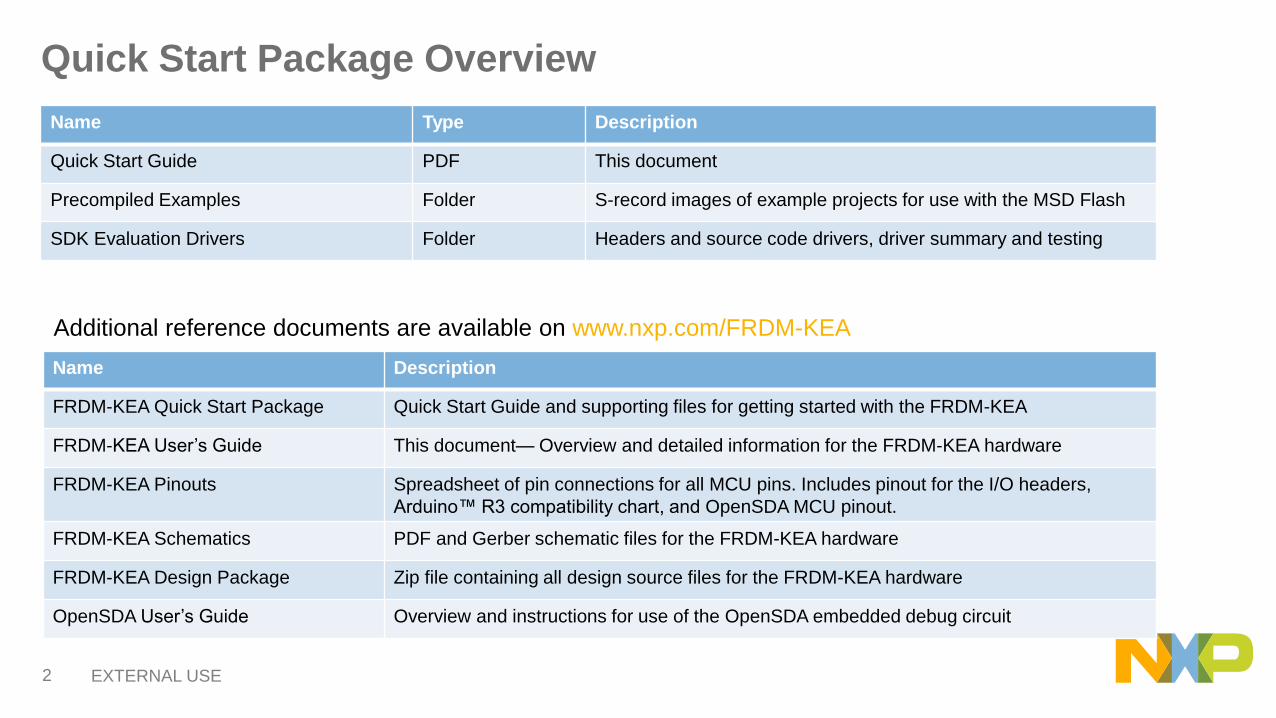
Step 1: Power up the Board – Is it powered on correctly?
• When powered through USB, LEDs D2 and D3 should light green
• FRDM-KEA boards ship with a 2-in-1 demo code
example pre-installed
• When you power the board, it will default to the
Blinking LED demo
• The RGB LED D11 will blink
• If you see this initially when powered, the correct
firmware is running

EXTERNAL USE14
Step 1: Power up the Board – Is it powered on correctly?
• Switch between code example projects
using push buttons SW2 and SW3
• The buttons are located on the edge of
the board opposite the microUSB port.
SW2SW3

EXTERNAL USE15
Step 3: Running Code Example #1 (Blinking LED Demo)
Code Example #1 allows D11 (RGB LED) to
illuminate in response to turning R13
(Potentiometer). The LED color will change as
the potentiometer position is adjusted
• The Blinking LED Demo uses ADC and FTM
• FTM interrupts toggles the RGB LED D11 at a frequency controlled by the value of the ADC
• ADC controls the blink period and LED selection (red, green, or blue)
• Dialing the potentiometer R13 will cause D11 to change frequency or color depending on the resistance
R13
D11

EXTERNAL USE16
Step 3: Running Code Example #2 (Dimming LED Demo)
Code Example #2 modulates the brightness of
LED as you turn the potentiometer
• Press SW2
• All three LEDs within D11 will turn on
• This will combine to produce white light
• The Dimming LED Demo uses RTC and ADC
to modulate LD brightness
• RTC interrupt functions as a PWM and ADC
value determines duty-cycle. A long duty-cycle,
means LED is on for longer portion of period.
Perceived by the human eye as brighter light
• Dial the potentiometer R13 and observe LED
change brightness
EXTERNAL USE17
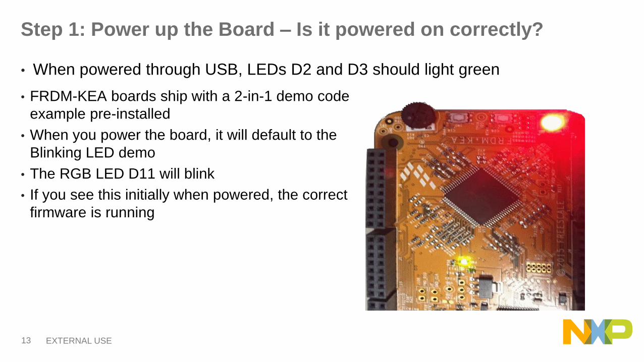
Sample Drivers
• Peripheral Drivers
− ACMP
− ADC_FIFO
− ADC_Interrupt
− ADC_Polling
− Bitband
− BME
− CRC
− FLASH_FTMRE
− FTM_Combine
− FTM_DualEdge
− FTM_EPWM
− FTM_OutputCompare
− GPIO
− I2C_MasterInt
− I2C_MasterPoll
− I2C_Slave
• Continued…
− ICS_FEE
− ICS_FEI
− WDOG
− KBI
− PIT
− PMC
− PWT
− RTC
− SPI_MasterInt
− SPI_MasterPoll
− SPI_Slave
− UART_Interrupt
− UART_Loopback
− UART_Polling
− WDOG
A step by step KEA sample
driver Integration Guide in S32
Design Studio is available to
assist loading drivers and
code examples for each into a
S32DS project
EXTERNAL USE18
Documentation and Reference Material
• Documentation Links
− FRDM Factsheet
− KEA128 Sub-Family Datasheet
− KEAZN64/KEAZN32 Sub-Family Datasheet
− S32 Design Studio Factsheet
• Application Notes
− KEA Application Cookbook
− KEA Family Appnote
− DC Motor Control using PWT
− Migrating from 8-bit to KEA
• Reference Manuals
− KEA128 Sub-Family Reference Manual
− KEAZN64/KEAZN32 Sub-Family Reference Manual

EXTERNAL USE19
Development Tools Ecosystem
IDE / Compilers & Debuggers
• Free S32 Design Studio IDE
• Processor Expert coming in 2016
• Free KDS IDE support w/ Processor Expert support
• CodeWarrior 10.6 IDE w/ Processor Expert support
• Keil w/ CMSIS compliant drivers
• IAR
• Cosmic IDE for Kinetis ARM based MCUs
Programmers
• OpenSDA
• P&E MultiLink
Support Tools:
• FREEMASTER run time debug monitor and
instrumentation/calibration tool
• MCAT – Motor Control Application Tool
• Automotive math and motor control library for Cortex®
M0+ based products

EXTERNAL USE20
Kinetis KEA Family — Feature Set Comparison
MCU
FEATURES
Flash RAMEE
PROMFREQ MS-CAN SCI SPI ATD PWT Flex-Tim ACMP IIC GPIO Packages
KEAZ128 128K 16K emulate 48MHz 1 3 2 16c12b 16c+2c+2c
16b2 2 Up to 71 64/80 LQFP
KEAZ64 64K 8K emulate 48MHz 1 3 2 16c12b 16c+2c+2c
16b2 2 Up to 71 64/80 LQFP
KEAZN64 64K 4K 256B 40MHz 0 3 2 16c12b NA6c+2c+2c
16b2 2 Up to 57 32/64 LQFP
KEAZN32 32K 4K 256B 40MHz 0 3 2 16c12b NA6c+2c+2c
16b2 2 Up to 57 32/64 LQFP
KEAZN16 16K 2K 256B 40MHz 0 3 2 16c12b NA6c+2c+2c
16b2 2 Up to 57 32/64 LQFP
KEAZN8 8K 1K emulate 48MHz 0 1 1 12c12b 1 6c+2c 16b 2 1 Up to 2216 TSSOP/
24 QFN
Available Freescale Freedom development kit

EXTERNAL USE21
Ordering Information
Hardware Type Part Number Package Pricing
Evaluation (EVB) NXP Freedom Board FRDM-KEAZ128Q80 80 LQFP $29
Evaluation (EVB) NXP Freedom Board FRDM-KEAZ64Q80 64 LQFP $29
Evaluation (EVB) NXP Freedom Board FRDM-KEAZN32Q64 64 LQFP $29

EXTERNAL USE22
OpenSDA 1 of 2
OpenSDA is an open-standard serial and debug adapter. It bridges serial and debug communications between a USB host and an
embedded target processor. OpenSDA software includes a flash-resident USB mass-storage device (MSD) bootloader and a collection of
OpenSDA Applications. FRDM-KL26Z comes with the MSD Flash Programmer OpenSDA Application preinstalled.
Follow these instructions to run the OpenSDA Bootloader and update or change the installed OpenSDA Application.
IMPORTANT NOTE: Follow the “Load an OpenSDA
Application” instructions to update the MSD Flash
Programmer on your FRDM-KL26Z to the latest version. It is
likely that the version provided in this package is newer than
what was preprogrammed on your FRDM-KL26Z.
Enter OpenSDA Bootloader Mode
1. Unplug the USB cable if attached
2. Press and hold the Reset button (SW2)
3. Plug in a USB cable (not included) between a USB host
and the OpenSDA USB connector (labeled “SDA”)
4. Release the Reset button
A removable drive should now be visible in the host file
system with a volume label of BOOTLOADER. You are now
in OpenSDA Bootloader mode.
Load an OpenSDA Application
1. While in OpenSDA Bootloader mode, double-click
SDA_INFO.HTML in the BOOTLOADER drive. A web browser will
open the OpenSDA homepage containing the name and version of
the installed Application. This information can also be read as text
directly from SDA_INFO.HTML
2. Locate the OpenSDA Applications folder in the FRDM-KEA Quick
Start Package
3. Copy & paste or drag & drop the MSD Flash Programmer
Application to the BOOTLOADER drive
4. Unplug the USB cable and plug it in again. The new OpenSDA
Application should now be running and a FRDM-KEA drive should
be visible in the host file system
You are now running the latest version of the MSD Flash Programmer.
Use this same procedure to load other OpenSDA Applications.

EXTERNAL USE23
OpenSDA 2 of 2
The MSD Flash Programmer is a composite USB application that provides a virtual serial port and an easy and convenient way to program
applications into the KEA MCU. It emulates a FAT16 file system, appearing as a removable drive in the host file system with a volume label
of FRDM-KEA. Raw binary and Motorola S-record files that are copied to the drive are programmed directly into the flash of the KEA and
executed automatically. The virtual serial port enumerates as a standard serial port device that can be opened with standard serial terminal
applications.
NOTE: Flash programming with the MSD Flash Programmer is currently only
supported on Windows operating systems. However, the virtual serial port has
been successfully tested on Windows, Linux and Mac operating systems.
Using the MSD Flash Programmer
1. Locate the Precompiled Examples folder in the FRDM-
KEAZ128 Quick Start Package
2. Copy & paste or drag & drop one of the .srec files to the
FRDM-KEA drive
The new application should now be running on the FRDM-KEA.
Starting with v1.03 of the MSD Flash Programmer, you can
program repeatedly without the need to unplug and reattach the
USB cable before reprogramming.
Drag one of the .srec code examples from the KEA code example
folder onto the FRDM-KEA board over USB to reprogram the
preloaded code example to another example.
Using the Virtual Serial Port
1. Determine the symbolic name assigned to the FRDM-KEAZ128 virtual
serial port. In Windows open Device Manager and look for the COM
port named “PEMicro/Freescale – CDC Serial Port”.
2. Open the serial terminal emulation program of your choice. Examples
for Windows include Tera Term, PuTTY, and HyperTerminal
3. Program one of the “code example programs” from the Code
Examples folder using the MSD Flash Programmer.
4. Configure the terminal program. Most embedded examples use 8 data
bits, no parity bits, and one stop bit (8-N-1). Match the baud rate to the
selected serial test application and open the port.
5. Press and release the Reset button (SW0) at anytime to restart the
example application. Resetting the embedded application will not
affect the connection of the virtual serial port to the terminal program.
NOTE: Refer to the OpenSDA User’s Guide for a description of a known Windows
issue when disconnecting a virtual serial port while the COM port is in use.

EXTERNAL USE24
Recommendations
• For faster debugging, debug from RAM, because this cuts down the lengthy Flash erase operation cycles. Follow the Software Integration Guide (SWIG) for details.
• By default “New Project” in S32 Design Studio IDE makes application to run at 37.5 kHz Internal RC (IRC) oscillator. For faster performance, configure FLL to desired frequency and switch clock source to FLL before executing application code.
• Keep S32 Design Studio IDE and OpenSDA firmware Up-to-date for best results
• Post Technical Questions on NXP community for Kinetis MCUs.
• Useful Links:
− KEA Webpage
− FRDM-KEA Page
− S32 Design Studio
− NXP Community