Quick Start Guide - CNET...
50
S2700&S3700&S5700&S6700 Series Ethernet Switches Quick Start Guide Issue 12 Date 2013-07-25 HUAWEI TECHNOLOGIES CO., LTD.
Transcript of Quick Start Guide - CNET...

S2700&S3700&S5700&S6700 Series EthernetSwitches
Quick Start Guide
Issue 12
Date 2013-07-25
HUAWEI TECHNOLOGIES CO., LTD.

Copyright © Huawei Technologies Co., Ltd. 2013. All rights reserved.
No part of this document may be reproduced or transmitted in any form or by any means without prior writtenconsent of Huawei Technologies Co., Ltd. Trademarks and Permissions
and other Huawei trademarks are trademarks of Huawei Technologies Co., Ltd.All other trademarks and trade names mentioned in this document are the property of their respective holders. NoticeThe purchased products, services and features are stipulated by the contract made between Huawei and thecustomer. All or part of the products, services and features described in this document may not be within thepurchase scope or the usage scope. Unless otherwise specified in the contract, all statements, information,and recommendations in this document are provided "AS IS" without warranties, guarantees or representationsof any kind, either express or implied.
The information in this document is subject to change without notice. Every effort has been made in thepreparation of this document to ensure accuracy of the contents, but all statements, information, andrecommendations in this document do not constitute a warranty of any kind, express or implied.
Huawei Technologies Co., Ltd.Address: Huawei Industrial Base
Bantian, LonggangShenzhen 518129People's Republic of China
Website: http://enterprise.huawei.com
Issue 12 (2013-07-25) Huawei Proprietary and ConfidentialCopyright © Huawei Technologies Co., Ltd.
i
About This Document
Intended AudienceThis document describes hardware installation and basic configuration of theS2700/3700/5700/6700 series to help you understand S2700/3700/5700/6700 hardware andconfiguration.
This document is intended for:
l Network planning engineers
l Hardware installation engineers
l Commissioning engineers
l Onsite maintenance engineers
l System maintenance engineers
Symbol ConventionsThe symbols that may be found in this document are defined as follows.
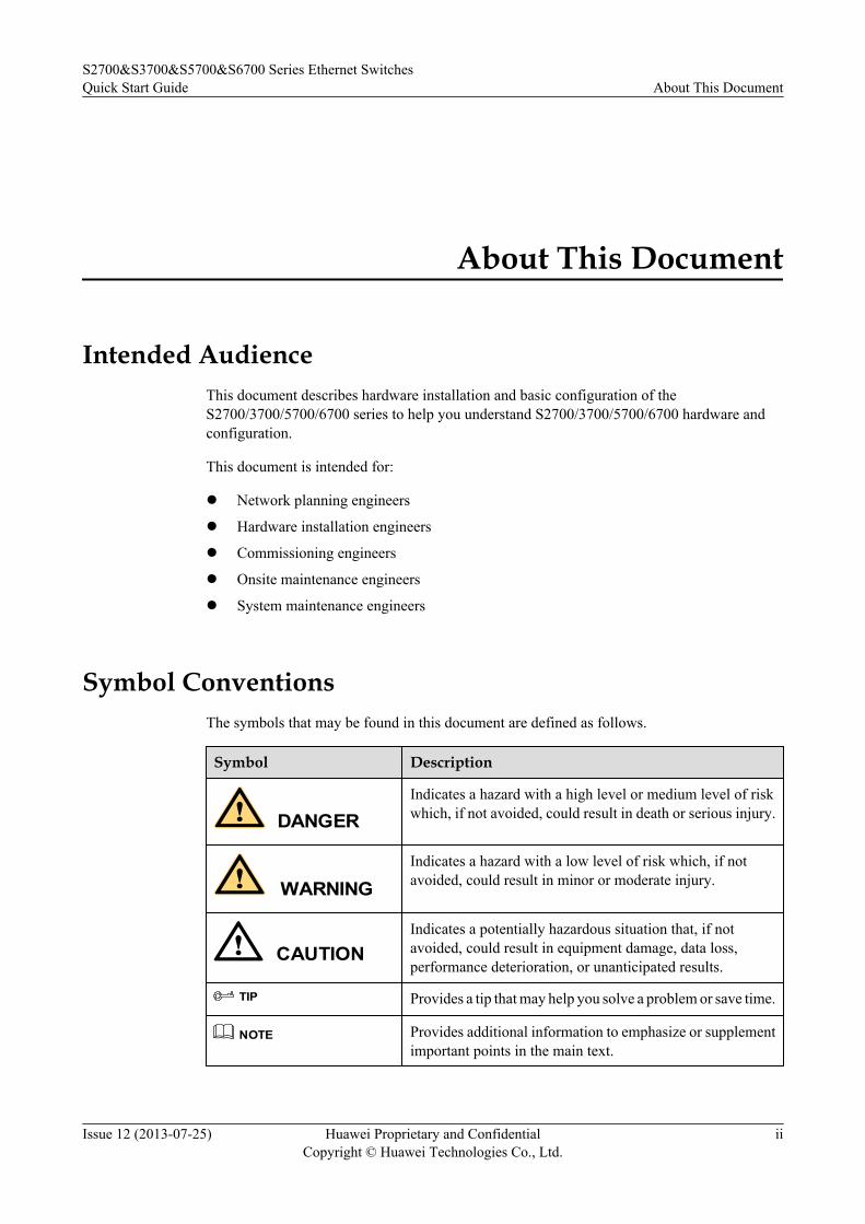
Symbol Description
DANGERIndicates a hazard with a high level or medium level of riskwhich, if not avoided, could result in death or serious injury.
WARNINGIndicates a hazard with a low level of risk which, if notavoided, could result in minor or moderate injury.
CAUTIONIndicates a potentially hazardous situation that, if notavoided, could result in equipment damage, data loss,performance deterioration, or unanticipated results.
TIP Provides a tip that may help you solve a problem or save time.
NOTE Provides additional information to emphasize or supplementimportant points in the main text.
S2700&S3700&S5700&S6700 Series Ethernet SwitchesQuick Start Guide About This Document
Issue 12 (2013-07-25) Huawei Proprietary and ConfidentialCopyright © Huawei Technologies Co., Ltd.
ii

Change HistoryChanges between document issues are cumulative. The latest document issue contains all thechanges made in earlier issues.
Issue 12 (2013-07-25)This version has the following updates:
The following information is modified:l S5710-HI installation instruction.l 2.4 Connecting Cables.
Issue 11 (2013-05-30)This version has the following updates:
The following information is added:
S5710-HI installation instruction.
The following information is modified:l 2.2 Installing a Chassis.l 2.3 Installing and Removing Device Modules.l 2.4 Connecting Cables.
Issue 10 (2013-02-08)This version has the following updates:
The documentation is modified according to updates in product features.
Issue 09 (2012-12-08)This version has the following updates:
Quick Installation Guide changes to Quick Start Guide
S2700&S3700&S5700&S6700 Series Ethernet SwitchesQuick Start Guide About This Document
Issue 12 (2013-07-25) Huawei Proprietary and ConfidentialCopyright © Huawei Technologies Co., Ltd.
iii

Contents
About This Document.....................................................................................................................ii
1 Product Introduction.....................................................................................................................1
2 Device Installation........................................................................................................................22.1 Preparing for Installation................................................................................................................................................32.2 Installing a Chassis.........................................................................................................................................................42.3 Installing and Removing Device Modules...................................................................................................................202.4 Connecting Cables........................................................................................................................................................232.5 Powering on the Device................................................................................................................................................30
3 Logging in to the Device............................................................................................................333.1 Logging In to the Switch Through the Console Interface............................................................................................343.2 Example for Configuring to Manage the SwitchThrough Telnet.................................................................................383.3 Logging In to the Web System Client..........................................................................................................................40
4 Service Deployment....................................................................................................................43
5 Where to Obtain Documentation.............................................................................................44
S2700&S3700&S5700&S6700 Series Ethernet SwitchesQuick Start Guide Contents
Issue 12 (2013-07-25) Huawei Proprietary and ConfidentialCopyright © Huawei Technologies Co., Ltd.
iv

1 Product Introduction
This section provides a brief introduction about the S2700/3700/5700/6700 series switches.
For details about the models included in the S2700/3700/5700/6700 series and specifications ofeach model, see "Overview" or "Chassis" in the S2700/3700/5700/6700 hardware description.
NOTE
To obtain the electronic hardware description manuals, see 5 Where to Obtain Documentation.
S2700&S3700&S5700&S6700 Series Ethernet SwitchesQuick Start Guide 1 Product Introduction
Issue 12 (2013-07-25) Huawei Proprietary and ConfidentialCopyright © Huawei Technologies Co., Ltd.
1

2 Device Installation
About This Chapter
This section describes how to install S2700/3700/5700/6700 switches, connect cables, poweron the switches, and check the switches after power-on.
2.1 Preparing for InstallationThis section describes the tools and accessories required for installation of theS2700/3700/5700/6700 series switches.
2.2 Installing a ChassisThis section describes the installation scenarios of the S2700/3700/5700/6700 series andinstallation methods in these scenarios.
2.3 Installing and Removing Device ModulesThis section describes how to install and remove various modules on theS2700/3700/5700/6700 series switches.
2.4 Connecting CablesThis section describes how to connect an S2700/3700/5700/6700 chassis to a network.
2.5 Powering on the DeviceThis section provides the checklist used to check the S2700/3700/5700/6700 switches beforeand after powering on the switches.
S2700&S3700&S5700&S6700 Series Ethernet SwitchesQuick Start Guide 2 Device Installation
Issue 12 (2013-07-25) Huawei Proprietary and ConfidentialCopyright © Huawei Technologies Co., Ltd.
2

2.1 Preparing for InstallationThis section describes the tools and accessories required for installation of theS2700/3700/5700/6700 series switches.
Installation Tools
S2700&S3700&S5700&S6700 Series Ethernet SwitchesQuick Start Guide 2 Device Installation
Issue 12 (2013-07-25) Huawei Proprietary and ConfidentialCopyright © Huawei Technologies Co., Ltd.
3

Accessories
2.2 Installing a ChassisThis section describes the installation scenarios of the S2700/3700/5700/6700 series andinstallation methods in these scenarios.
WARNINGThe S2700/3700/5700/6700 series Ethernet switches are class A products. Customers shouldtake preventative measures as the operating devices may cause radio interference.
S2700&S3700&S5700&S6700 Series Ethernet SwitchesQuick Start Guide 2 Device Installation
Issue 12 (2013-07-25) Huawei Proprietary and ConfidentialCopyright © Huawei Technologies Co., Ltd.
4
CAUTIONl Take ESD protection measures before the installation, for example, wear ESD gloves or ESD
wrist strap.l When installing multiple fan-free or intelligent-heat-dissipation devices in a cabinet or rack,
leave at least 1 U (1 U = 44.45 mm) distance between each two.l Leave at least 50 mm clearance at two sides and rear of each chassis for heat dissipation.l Preventing trips are required to fix AC terminals only in desk-mounting or wall-mounting,
and are not required in cabinet-mounting.
The S2700/3700/5700/6700 switches support the following installation scenarios:
l Desk-mountingl Wall-mountingl Cabinet- or rack-mountingl Network box-mounting
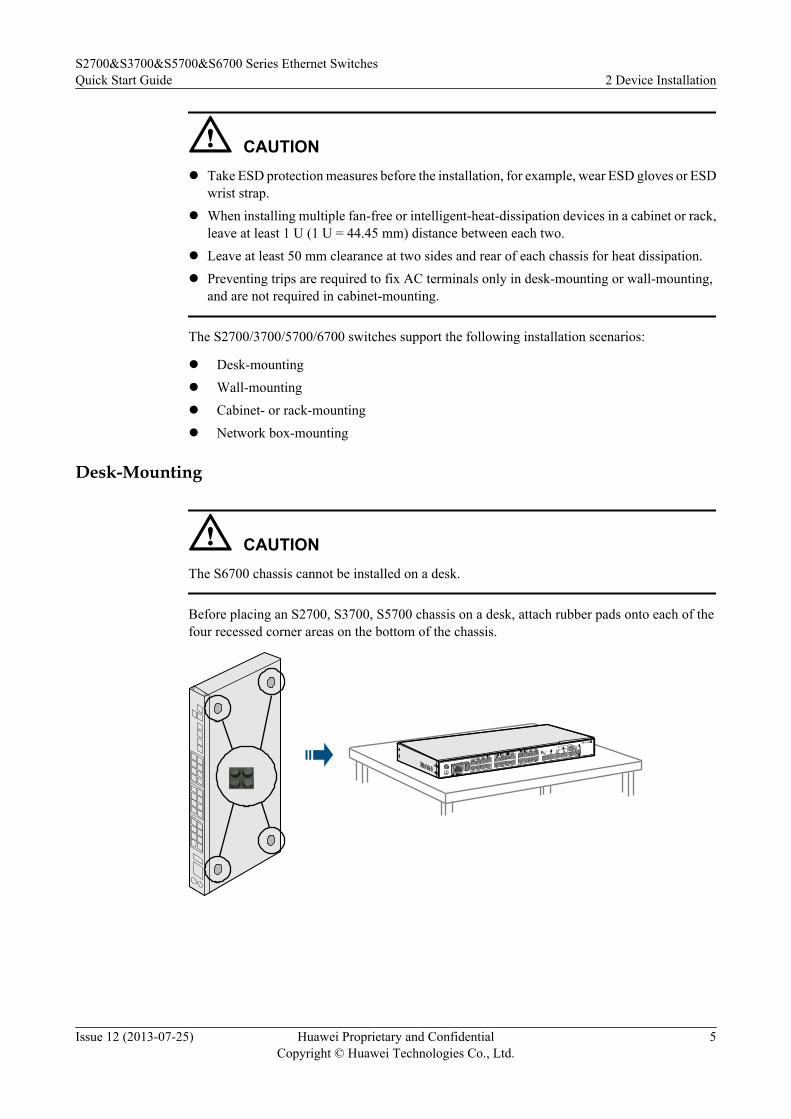
Desk-Mounting
CAUTIONThe S6700 chassis cannot be installed on a desk.
Before placing an S2700, S3700, S5700 chassis on a desk, attach rubber pads onto each of thefour recessed corner areas on the bottom of the chassis.
S2700&S3700&S5700&S6700 Series Ethernet SwitchesQuick Start Guide 2 Device Installation
Issue 12 (2013-07-25) Huawei Proprietary and ConfidentialCopyright © Huawei Technologies Co., Ltd.
5

Wall-Mounting
CAUTIONl The S6700, S5710-EI and S5710-HI cannot be wall-mounted.l Before drilling holes on a wall, make sure that no power cable is routed in the wall. Otherwise,
power cables in the wall may cause body injuries.l When a 220 mm deep S2700 or S3700 chassis needs to be installed on a wall, only two screws
are required to fix a mounting ear to the chassis.l The panel with interfaces must face down to protect the interfaces from water.l Ensure that there are no flammable or explosive materials near the chassis and no sundries
within 100 mm around the chassis.
1. Fix short mounting ears to both sides of the panel with interfaces using M4 screws.
M4
2. Use a marker to mark the positions of mounting holes according to the size of the chassisand positions of the mounting ears.
S2700&S3700&S5700&S6700 Series Ethernet SwitchesQuick Start Guide 2 Device Installation
Issue 12 (2013-07-25) Huawei Proprietary and ConfidentialCopyright © Huawei Technologies Co., Ltd.
6

3. Install expansion bolts in the wall.
a. Use a φ8 drill bit to drill 35 mm to 40 mm deep holes in the marked positions.
b. Insert expansion bolts into the holes and screw the nuts to fasten the expansion bolts.
S2700&S3700&S5700&S6700 Series Ethernet SwitchesQuick Start Guide 2 Device Installation
Issue 12 (2013-07-25) Huawei Proprietary and ConfidentialCopyright © Huawei Technologies Co., Ltd.
7

c. Remove the nuts.
4. Install the chassis on the wall.
S2700&S3700&S5700&S6700 Series Ethernet SwitchesQuick Start Guide 2 Device Installation
Issue 12 (2013-07-25) Huawei Proprietary and ConfidentialCopyright © Huawei Technologies Co., Ltd.
8

Cabinet- or Rack-Mounting
CAUTIONl When mounting a switch in a cabinet/rack with rack-mounting brackets, ensure that the rack-
mounting brackets are kept in a horizontal line in the mounting holes on the left and rightmounting rails of the cabinet/rack. If the rack-mounting brackets are not in a horizontal line,do not install the switch with force. Or the chassis may be distorted.
l When the ground point is located on one side of the chassis, the ground cable cannot beconnected when the chassis is in a cabinet. Connect the ground cable before installing thechassis in the cabinet.
l When a 220 mm deep S2700 or S3700 chassis needs to be installed in a cabinet, only twoscrews are required to fix a mounting ear to the chassis.
l The dimensions of an RPS1800 chassis are 442 mm x 310 mm x 43.6 mm (W x D x H), andthe chassis can be installed only in a 19-inch IEC cabinet.
l Mounting ears can be installed at two ends and the middle of each side on an RPS1800.l No guide rails are delivered with the chassis, and you need to buy appropriate guide rails
when the chassis needs to be installed in a cabinet or rack.
Table 2-1 lists the mounting ears and cabinets applicable to chassis of different dimensions.
Table 2-1 Applicable mounting ears and cabinets
Dimensions (W x D x H) Mounting Ear Cabinet
250 mm x 180 mm x 43.6 mm320 mm x 220 mm x 43.6 mm
Front mounting ear (1) 19-inch cabinet
442 mm x 220 mm x 43.6 mm Front mounting ears (2) 19-inch or 21-inch cabinet
442 mm x 220 mm x 43.6 mm442 mm x 310 mm x 43.6 mm
Front mounting ears (3) 19-inch cabinet
442 mm x 420 mm x 43.6 mm(S6700)
Front mounting ears (4) andguide rails
19-inch cabinet
442 mm x 420 mm x 43.6 mm(S5710-EI)
Front mounting ears (5) andrear mounting ear (1)
19-inch cabinet
442 mm x 420 mm x 43.6 mm(any switch except the S6700and S5710-EI )
Front mounting ears (4) 19-inch cabinet
S2700&S3700&S5700&S6700 Series Ethernet SwitchesQuick Start Guide 2 Device Installation
Issue 12 (2013-07-25) Huawei Proprietary and ConfidentialCopyright © Huawei Technologies Co., Ltd.
9

Dimensions (W x D x H) Mounting Ear Cabinet
442 mm x 470 mm x 86.1 mm l Front mounting ears (6)and rear mounting ears (2)
l Front mounting ears (6)and guide rails
l Cable managementframes and rear mountingears (2)
l Cable managementframes and guide rails
19-inch cabinet
Installing a Chassis of 250 mm x 180 mm x 43.6 mm or 320 mm x 220 mm x 43.6 mm
1. Install mounting ears.Fix mounting ears to both sides of the panel with interfaces using M4 screws.
M4
2. Install floating nuts.Install four floating nuts on the front mounting rails, two on each side. TheS2700/3700/5700/6700 chassis is 1 U high, so the distance between two floating nuts onone side is 1 U (one mounting hole between them). The floating nuts on the left and rightsides must be on the same horizontal line.
1U
1U=44.45mm
3. Install the chassis in the cabinet.
S2700&S3700&S5700&S6700 Series Ethernet SwitchesQuick Start Guide 2 Device Installation
Issue 12 (2013-07-25) Huawei Proprietary and ConfidentialCopyright © Huawei Technologies Co., Ltd.
10
M6>=1U
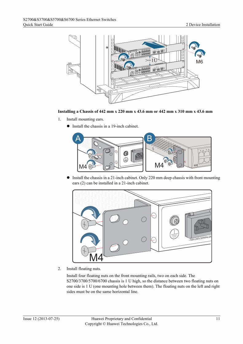
Installing a Chassis of 442 mm x 220 mm x 43.6 mm or 442 mm x 310 mm x 43.6 mm
1. Install mounting ears.l Install the chassis in a 19-inch cabinet.
M4 M4
A B
l Install the chassis in a 21-inch cabinet. Only 220 mm deep chassis with front mountingears (2) can be installed in a 21-inch cabinet.
2. Install floating nuts.Install four floating nuts on the front mounting rails, two on each side. TheS2700/3700/5700/6700 chassis is 1 U high, so the distance between two floating nuts onone side is 1 U (one mounting hole between them). The floating nuts on the left and rightsides must be on the same horizontal line.
S2700&S3700&S5700&S6700 Series Ethernet SwitchesQuick Start Guide 2 Device Installation
Issue 12 (2013-07-25) Huawei Proprietary and ConfidentialCopyright © Huawei Technologies Co., Ltd.
11

1U
1U=44.45mm
3. Install the chassis in the cabinet.
M6>=1U
Installing a Chassis of 442 mm x 420 mm x 43.6 mm
1. Install mounting ears.l 442 mm x 420 mm x 43.6 mm (any switch except the S5710-EI)
M4
l 442 mm x 420 mm x 43.6 mm (S5710-EI)
S2700&S3700&S5700&S6700 Series Ethernet SwitchesQuick Start Guide 2 Device Installation
Issue 12 (2013-07-25) Huawei Proprietary and ConfidentialCopyright © Huawei Technologies Co., Ltd.
12
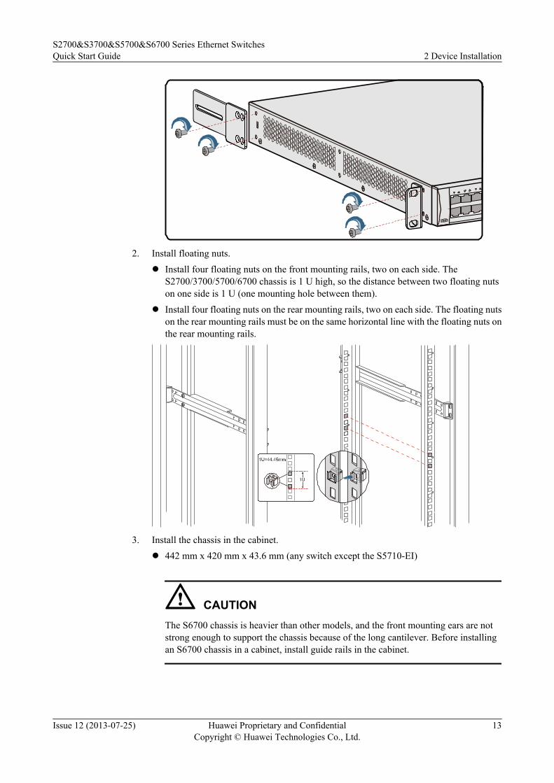
2. Install floating nuts.l Install four floating nuts on the front mounting rails, two on each side. The
S2700/3700/5700/6700 chassis is 1 U high, so the distance between two floating nutson one side is 1 U (one mounting hole between them).
l Install four floating nuts on the rear mounting rails, two on each side. The floating nutson the rear mounting rails must be on the same horizontal line with the floating nuts onthe rear mounting rails.
3. Install the chassis in the cabinet.l 442 mm x 420 mm x 43.6 mm (any switch except the S5710-EI)
CAUTIONThe S6700 chassis is heavier than other models, and the front mounting ears are notstrong enough to support the chassis because of the long cantilever. Before installingan S6700 chassis in a cabinet, install guide rails in the cabinet.
S2700&S3700&S5700&S6700 Series Ethernet SwitchesQuick Start Guide 2 Device Installation
Issue 12 (2013-07-25) Huawei Proprietary and ConfidentialCopyright © Huawei Technologies Co., Ltd.
13

M6>=1U
l 442 mm x 420 mm x 43.6 mm (S5710-EI)
a. Install guide rails for rear mounting ears on the rear mounting rails.
b. Hold the bottom of the chassis and move the chassis into the cabinet or rack. Alignthe rear mounting ears with the guide rails on the rear mounting rails and gentlyslide the chassis into the guide rails.
S2700&S3700&S5700&S6700 Series Ethernet SwitchesQuick Start Guide 2 Device Installation
Issue 12 (2013-07-25) Huawei Proprietary and ConfidentialCopyright © Huawei Technologies Co., Ltd.
14

c. Hold the bottom of the chassis with one hand and fix the front mounting ears ontothe front mounting rails with a screwdriver. Fix the rear mounting ears onto theguide rails.
Installing a Chassis of 442 mm x 470 mm x 87.2 mm
NOTE
The S5710-HI chassis is heavier than other models, and the mounting ears are not strong enough to supportthe chassis because of the long cantilever. Before installing an S5710-HI chassis in a cabinet, install guiderails in the cabinet.
S2700&S3700&S5700&S6700 Series Ethernet SwitchesQuick Start Guide 2 Device Installation
Issue 12 (2013-07-25) Huawei Proprietary and ConfidentialCopyright © Huawei Technologies Co., Ltd.
15
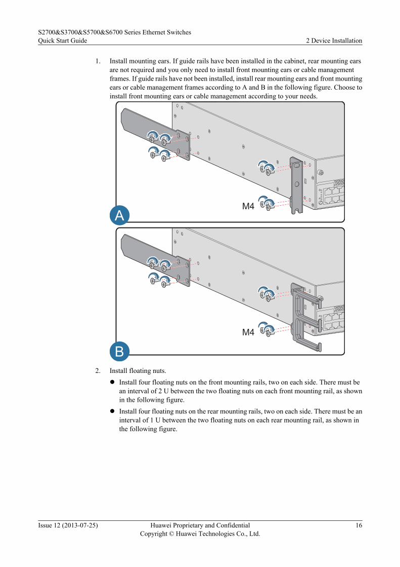
1. Install mounting ears. If guide rails have been installed in the cabinet, rear mounting earsare not required and you only need to install front mounting ears or cable managementframes. If guide rails have not been installed, install rear mounting ears and front mountingears or cable management frames according to A and B in the following figure. Choose toinstall front mounting ears or cable management according to your needs.
M4
M4
A
B2. Install floating nuts.
l Install four floating nuts on the front mounting rails, two on each side. There must bean interval of 2 U between the two floating nuts on each front mounting rail, as shownin the following figure.
l Install four floating nuts on the rear mounting rails, two on each side. There must be aninterval of 1 U between the two floating nuts on each rear mounting rail, as shown inthe following figure.
S2700&S3700&S5700&S6700 Series Ethernet SwitchesQuick Start Guide 2 Device Installation
Issue 12 (2013-07-25) Huawei Proprietary and ConfidentialCopyright © Huawei Technologies Co., Ltd.
16

1U
2U
3. Install the chassis in the cabinet.
a. Install guide rails for rear mounting ears on the rear mounting rails.
b. NOTE
Skip to step c if you choose to install cable management frames.
Place M6 screws on the two floating nuts at the bottom of front mounting rails. Reservea clearance between the screw nuts and floating nuts for installing front mounting ears.
S2700&S3700&S5700&S6700 Series Ethernet SwitchesQuick Start Guide 2 Device Installation
Issue 12 (2013-07-25) Huawei Proprietary and ConfidentialCopyright © Huawei Technologies Co., Ltd.
17

2U
c. Hold the bottom of the chassis and move the chassis into the cabinet or rack. Alignthe rear mounting ears with their guide rails and gently slide the chassis into the guiderails.
NOTE
l If cable management frames are installed on the chassis, do not lift the chassis by holdingthe cable management frames. Or the cable management frames will be curved.
l If front mounting ears are installed on the chassis, fix the recesses at the bottom of frontmounting ears on the M6 screws.
d. Fasten the M6 screws on the front mounting rails to secure the chassis.
S2700&S3700&S5700&S6700 Series Ethernet SwitchesQuick Start Guide 2 Device Installation
Issue 12 (2013-07-25) Huawei Proprietary and ConfidentialCopyright © Huawei Technologies Co., Ltd.
18
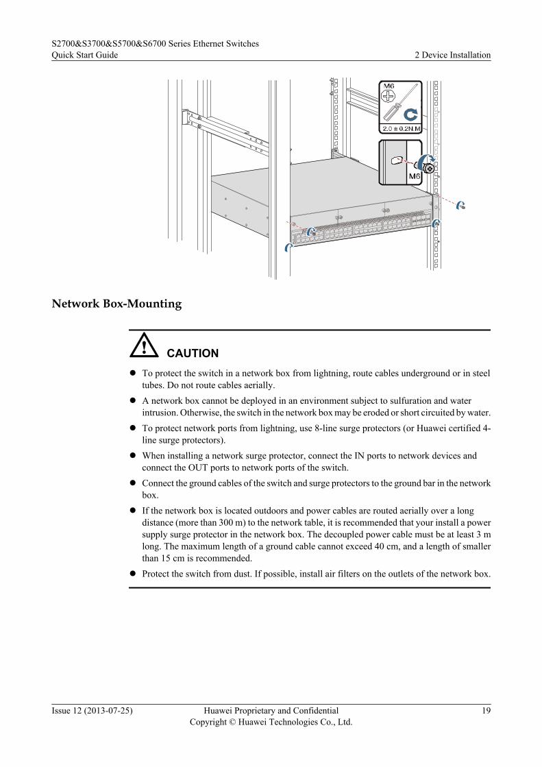
Network Box-Mounting
CAUTIONl To protect the switch in a network box from lightning, route cables underground or in steel
tubes. Do not route cables aerially.l A network box cannot be deployed in an environment subject to sulfuration and water
intrusion. Otherwise, the switch in the network box may be eroded or short circuited by water.l To protect network ports from lightning, use 8-line surge protectors (or Huawei certified 4-
line surge protectors).l When installing a network surge protector, connect the IN ports to network devices and
connect the OUT ports to network ports of the switch.l Connect the ground cables of the switch and surge protectors to the ground bar in the network
box.l If the network box is located outdoors and power cables are routed aerially over a long
distance (more than 300 m) to the network table, it is recommended that your install a powersupply surge protector in the network box. The decoupled power cable must be at least 3 mlong. The maximum length of a ground cable cannot exceed 40 cm, and a length of smallerthan 15 cm is recommended.
l Protect the switch from dust. If possible, install air filters on the outlets of the network box.
S2700&S3700&S5700&S6700 Series Ethernet SwitchesQuick Start Guide 2 Device Installation
Issue 12 (2013-07-25) Huawei Proprietary and ConfidentialCopyright © Huawei Technologies Co., Ltd.
19

≥3m
Switch
Network portsurge protector
Power supplysurge protector
OUT
<40cm
IN
Gro
und
bar
ground cable
2.3 Installing and Removing Device ModulesThis section describes how to install and remove various modules on theS2700/3700/5700/6700 series switches.
Installing and Removing a Power Module
CAUTIONl Power modules and fan modules of the S2700/3700/5700/6700 series switches are hot
swappable. The procedures for installing and removing a fan module are the same as theprocedure for installing and removing a power module.
l Before installing a power module, remove the filler panel from the power slot.
Install the power module into the power slot of the chassis and fasten the captive screws on thepanel of the power module. When you remove the power module, reverse the procedure.
S2700&S3700&S5700&S6700 Series Ethernet SwitchesQuick Start Guide 2 Device Installation
Issue 12 (2013-07-25) Huawei Proprietary and ConfidentialCopyright © Huawei Technologies Co., Ltd.
20

NOTE
A 1150 W AC power module can be installed on an S5710-EI and S5710-HI PoE switch. After installation,this power module extrudes out of the chassis, as shown in Figure 2-1.
Figure 2-1 1150 W AC power module on an S5710-EI PoE switch
Installing a Front Card
CAUTIONl Cards of the S3700-HI, S5700-HI, S5710-EI and S5710-HI are hot swappable. Cards of the
other modules are not hot swappable.l A 4-port GE optical interface card or 4-port 10GE optical interface card must be installed
together with an external channel card (except on the S5700-HI). Otherwise, the interfacecard cannot work.
l Before installing a front card, remove the filler panel from the front card slot.
1. Turn the eject levers of the front card 45 degrees outward. Push the card into the chassiswith your thumbs (below the captive screws), until both captive screws are completely inthe chassis.
S2700&S3700&S5700&S6700 Series Ethernet SwitchesQuick Start Guide 2 Device Installation
Issue 12 (2013-07-25) Huawei Proprietary and ConfidentialCopyright © Huawei Technologies Co., Ltd.
21
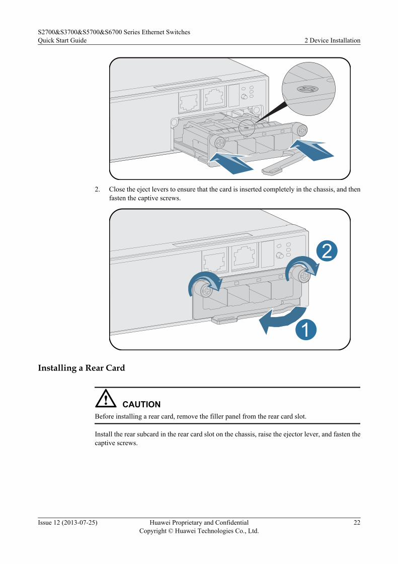
2. Close the eject levers to ensure that the card is inserted completely in the chassis, and thenfasten the captive screws.
1
2
Installing a Rear Card
CAUTIONBefore installing a rear card, remove the filler panel from the rear card slot.
Install the rear subcard in the rear card slot on the chassis, raise the ejector lever, and fasten thecaptive screws.
S2700&S3700&S5700&S6700 Series Ethernet SwitchesQuick Start Guide 2 Device Installation
Issue 12 (2013-07-25) Huawei Proprietary and ConfidentialCopyright © Huawei Technologies Co., Ltd.
22

Removing the Filler Panel from the RPS1800 Power Module Slot
Hold the upper edge of the filler panel and pull the filler panel downward. Do not pull the fillerpanel horizontally.
√ ×
Installing an RPS1800 Power Module
Move the white button leftward to loosen the ejector lever, and pull out the ejector lever. Installthe power module into the slot and push the ejector lever inside. Move the white button rightwardto lock the ejector lever. When you remove the RPS1800 power module, reverse the procedure.
2.4 Connecting CablesThis section describes how to connect an S2700/3700/5700/6700 chassis to a network.
S2700&S3700&S5700&S6700 Series Ethernet SwitchesQuick Start Guide 2 Device Installation
Issue 12 (2013-07-25) Huawei Proprietary and ConfidentialCopyright © Huawei Technologies Co., Ltd.
23

CAUTION
l Do not install power cables on a chassis with power on because this will cause body injuries.
l Do not power on the chassis before you finish installing the chassis and connecting cables.
l Ensure that the PGND cable on the chassis is grounded. The ground point on a network box,cabinet, or rack must be properly grounded. If the network box, cabinet, or rack has anti-rustcoating, you can scrape off the paint around the ground point to ensure reliable grounding.
Connecting the PGND Cable
Connect the M4 connector of the PGND cable to the chassis chassis and the M6 connector to aground point. The PGND cable is in yellow and green.
Connecting Power Cablesl Connect the DC power cable. Connect the positive and negative lines of the DC power
cable to the positive and negative studs on the chassis, as shown in the following figure.Use screws to fix the OT terminals of the power cable on the chassis. The black line is the-48 V positive line and must be connected to the RTN(+) stud on the DC power supply.The blue line is the -48 V negative line and must be connected to the NEG(-) stud on theon the DC power supply.
l Connect the AC power cable.
S2700&S3700&S5700&S6700 Series Ethernet SwitchesQuick Start Guide 2 Device Installation
Issue 12 (2013-07-25) Huawei Proprietary and ConfidentialCopyright © Huawei Technologies Co., Ltd.
24

CAUTIONAs an accessory delivered with the chassis, the AC power cable can only be used on thischassis. Do not use it on any other devices.
Some box switches have a jack reserved for the AC power cable locking latch beside theAC power socket, as shown in the following figure.
NOTE
l You need to prepare the AC power terminal locking latch yourself if you need it.l An AC power terminal locking latch is delivered with a pluggable 150 W AC power module,
170 W AC power module, 580 W AC power module, 1150 W AC power module, and RPS1800.
An AC power terminal locking latch can prevent an AC power cable from falling orloosening. Secure an AC power cable with a locking latch as shown in the following figure.
l Connect the RPS power cable. Connect the RPS power cable to the switch according toFigure A, and connect the RPS power cable to the RPS1800 power supply system accordingto Figure B.
NOTE
The S5700-26X-SI-12S-AC, S5700S-LI series and S5700-LI series, except for the S5700-10P-PWR-LI-AC and S5700-10P-LI-AC, can receive power from an RPS1800.
A
1
2
S2700&S3700&S5700&S6700 Series Ethernet SwitchesQuick Start Guide 2 Device Installation
Issue 12 (2013-07-25) Huawei Proprietary and ConfidentialCopyright © Huawei Technologies Co., Ltd.
25
B
1
2
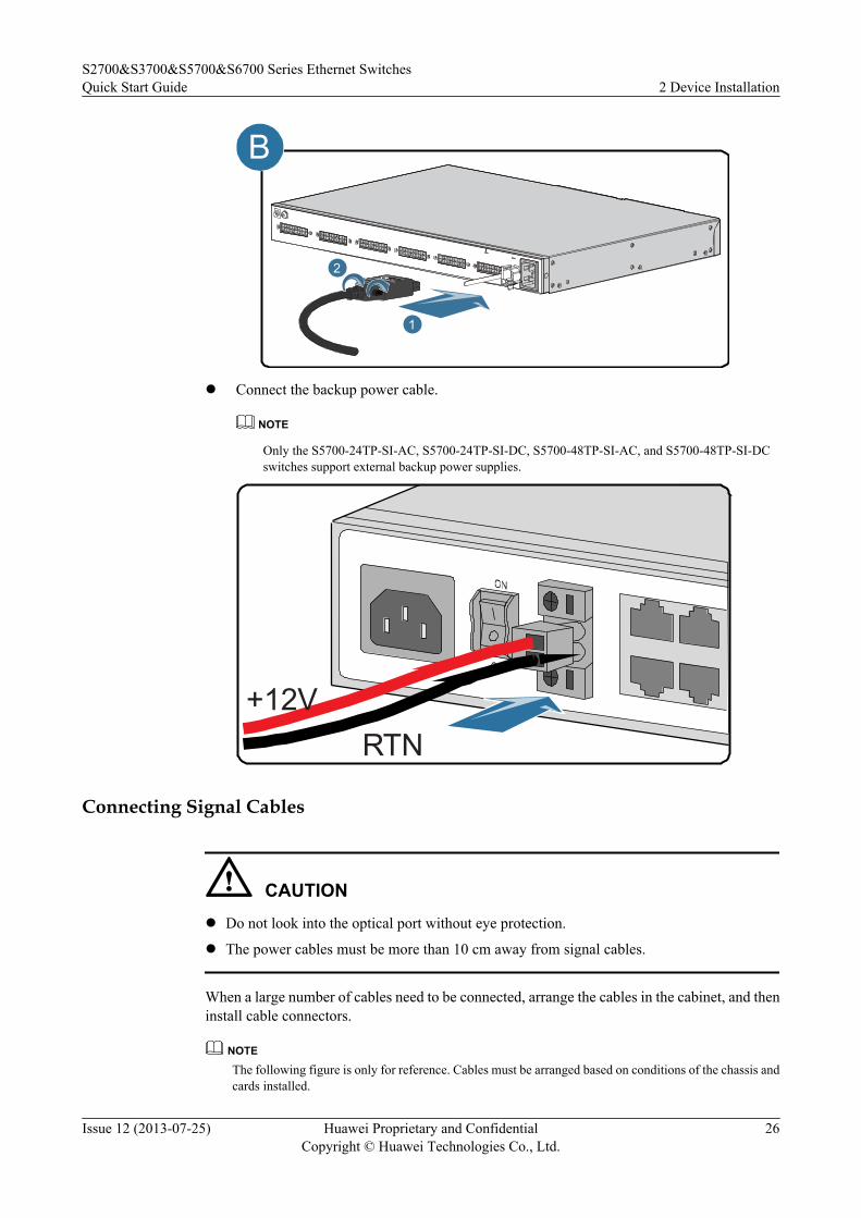
l Connect the backup power cable.
NOTE
Only the S5700-24TP-SI-AC, S5700-24TP-SI-DC, S5700-48TP-SI-AC, and S5700-48TP-SI-DCswitches support external backup power supplies.
RTN+12V
Connecting Signal Cables
CAUTIONl Do not look into the optical port without eye protection.
l The power cables must be more than 10 cm away from signal cables.
When a large number of cables need to be connected, arrange the cables in the cabinet, and theninstall cable connectors.
NOTE
The following figure is only for reference. Cables must be arranged based on conditions of the chassis andcards installed.
S2700&S3700&S5700&S6700 Series Ethernet SwitchesQuick Start Guide 2 Device Installation
Issue 12 (2013-07-25) Huawei Proprietary and ConfidentialCopyright © Huawei Technologies Co., Ltd.
26

Optical fiber
Cable tie
Fiber binding stap
Power cable
Ethernet network cable
Connect Stack CablesTable 2-2 lists the interfaces of the S2700/S3700/5700/6700 series switches that can connect tostack cables.
Table 2-2 Stack description table
Device Series StackConnection Mode
Stack Port Stack Cable
S2700-52PS2710-SI
Stack port Two SFP ports (ID:49/50)
1.5 m SFP copper cable
S2750-EI Stack port Two SFP ports (ID:1/2)
l 1 m passive SFP+ coppercable
l 3 m passive SFP+ coppercable
l 10 m active SFP+ coppercable
l 3 m, 10 m AOC cablesl Stack-specific optical module
and optical fiber
S3700-28TP Stack port Two SFP ports (ID:25/26)
1.5 m SFP copper cable
S3700-52P Stack port Two SFP ports (ID:49/50)
1.5 m SFP copper cable
S2700&S3700&S5700&S6700 Series Ethernet SwitchesQuick Start Guide 2 Device Installation
Issue 12 (2013-07-25) Huawei Proprietary and ConfidentialCopyright © Huawei Technologies Co., Ltd.
27

Device Series StackConnection Mode
Stack Port Stack Cable
S5700-P-LI(Model withuplink GE ports)
Stack port l V200R001: last twoSFP ports
l V200R002 and laterversions: last fourSFP ports
l 1 m passive SFP+ coppercable
l 10 m active SFP+ coppercable
l 3 m, 10 m AOC cables(applicable in V200R003C00and later versions)
S5700-X-LI(Model withuplink 10GEports)
Stack port Last four SFP+ ports l 1 m passive SFP+ coppercable
l 3 m passive SFP+ coppercable
l 10 m active SFP+ coppercable
l 3 m, 10 m AOC cables(applicable in V200R003C00and later versions)
l SFP+ optical module and SFP+ optical fiber
S5700-SI Stack card Two ports on a stackcard
l 1 m PCIe cablel 3 m PCIe cable
S5700-EI Stack card Two ports on a stackcard
l 1 m PCIe cablel 3 m PCIe cable
S5710-LI Stack card Two ports on a stackcard
1 m PCIe cable
S5710-EI Stack port Any 10GE ports,including the four fixedSFP+ ports and ports onthe rear SFP+ card.(The S5710-EIsupports two cards, andeach card provides two10GE ports.)
l 1 m passive SFP+ coppercable
l 3 m passive SFP+ coppercable
l 10 m active SFP+ coppercable
l 3 m, 10 m AOC cables(applicable in V200R003C00and later versions)
l SFP+ optical module and SFP+ optical fiber
S2700&S3700&S5700&S6700 Series Ethernet SwitchesQuick Start Guide 2 Device Installation
Issue 12 (2013-07-25) Huawei Proprietary and ConfidentialCopyright © Huawei Technologies Co., Ltd.
28
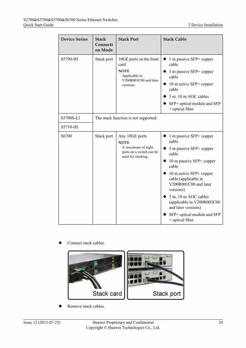
Device Series StackConnection Mode
Stack Port Stack Cable
S5700-HI Stack port 10GE ports on the frontcardNOTE
Applicable inV200R003C00 and laterversions.
l 1 m passive SFP+ coppercable
l 3 m passive SFP+ coppercable
l 10 m active SFP+ coppercable
l 3 m, 10 m AOC cablesl SFP+ optical module and SFP
+ optical fiber
S5700S-LI The stack function is not supported.
S5710-HI
S6700 Stack port Any 10GE portsNOTE
A maximum of eightports on a switch can beused for stacking.
l 1 m passive SFP+ coppercable
l 3 m passive SFP+ coppercable
l 10 m passive SFP+ coppercable
l 10 m active SFP+ coppercable (applicable inV200R001C00 and laterversions)
l 3 m, 10 m AOC cables(applicable in V200R003C00and later versions)
l SFP+ optical module and SFP+ optical fiber
l Connect stack cables.
l Remove stack cables.
S2700&S3700&S5700&S6700 Series Ethernet SwitchesQuick Start Guide 2 Device Installation
Issue 12 (2013-07-25) Huawei Proprietary and ConfidentialCopyright © Huawei Technologies Co., Ltd.
29

2.5 Powering on the DeviceThis section provides the checklist used to check the S2700/3700/5700/6700 switches beforeand after powering on the switches.
Checklist before power-on
CAUTION
Do not frequently power on and off a switch.
No. Item Method
1 The chassis is installed in a position that meets therequirements specified in the engineering designdocument.
View
2 There are no fingerprints, stains, or scratches on thesurface of the chassis.
View
3 Mechanical parts of the cabinet are correctly installed inthe cabinet and comply with the installation standards. Noparts are loosened or damaged.
View
4 All the screws are fastened. View
5 No objects are placed on the chassis. View
6 There is at least 50 mm clearance between the cabinet andboth sides of the chassis for heat dissipation.
Measure
7 The signal cables are not damaged or broken and have nosplice.
View
8 The connectors of signal cables are clean and intact andare connected to interfaces safely. Wires of cables arefixed.
View
9 Both ends of signal cables are clearly labeled and the labeltext is in the same direction.
View
S2700&S3700&S5700&S6700 Series Ethernet SwitchesQuick Start Guide 2 Device Installation
Issue 12 (2013-07-25) Huawei Proprietary and ConfidentialCopyright © Huawei Technologies Co., Ltd.
30
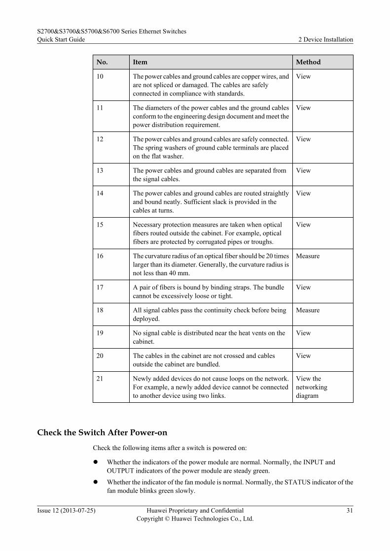
No. Item Method
10 The power cables and ground cables are copper wires, andare not spliced or damaged. The cables are safelyconnected in compliance with standards.
View
11 The diameters of the power cables and the ground cablesconform to the engineering design document and meet thepower distribution requirement.
View
12 The power cables and ground cables are safely connected.The spring washers of ground cable terminals are placedon the flat washer.
View
13 The power cables and ground cables are separated fromthe signal cables.
View
14 The power cables and ground cables are routed straightlyand bound neatly. Sufficient slack is provided in thecables at turns.
View
15 Necessary protection measures are taken when opticalfibers routed outside the cabinet. For example, opticalfibers are protected by corrugated pipes or troughs.
View
16 The curvature radius of an optical fiber should be 20 timeslarger than its diameter. Generally, the curvature radius isnot less than 40 mm.
Measure
17 A pair of fibers is bound by binding straps. The bundlecannot be excessively loose or tight.
View
18 All signal cables pass the continuity check before beingdeployed.
Measure
19 No signal cable is distributed near the heat vents on thecabinet.
View
20 The cables in the cabinet are not crossed and cablesoutside the cabinet are bundled.
View
21 Newly added devices do not cause loops on the network.For example, a newly added device cannot be connectedto another device using two links.
View thenetworkingdiagram
Check the Switch After Power-on
Check the following items after a switch is powered on:
l Whether the indicators of the power module are normal. Normally, the INPUT andOUTPUT indicators of the power module are steady green.
l Whether the indicator of the fan module is normal. Normally, the STATUS indicator of thefan module blinks green slowly.
S2700&S3700&S5700&S6700 Series Ethernet SwitchesQuick Start Guide 2 Device Installation
Issue 12 (2013-07-25) Huawei Proprietary and ConfidentialCopyright © Huawei Technologies Co., Ltd.
31

NOTE
l To check whether a switch is running properly after it is powered on, check the indicators of the powermodule and the PWR and SYS indicators of the switch.
l For details about the indicators on the S2700/3700/5700/6700 series switches, see the description ofindicators in the Hardware Description.
S2700&S3700&S5700&S6700 Series Ethernet SwitchesQuick Start Guide 2 Device Installation
Issue 12 (2013-07-25) Huawei Proprietary and ConfidentialCopyright © Huawei Technologies Co., Ltd.
32
3 Logging in to the Device
About This Chapter
This section describes how to log in to the device.
3.1 Logging In to the Switch Through the Console Interface
3.2 Example for Configuring to Manage the SwitchThrough Telnet
3.3 Logging In to the Web System Client
S2700&S3700&S5700&S6700 Series Ethernet SwitchesQuick Start Guide 3 Logging in to the Device
Issue 12 (2013-07-25) Huawei Proprietary and ConfidentialCopyright © Huawei Technologies Co., Ltd.
33

3.1 Logging In to the Switch Through the Console Interface
Context
When establishing the configuration environment through the console interface, you can log into the S2700/3700/5700/6700 through the HyperTerminal in Windows.
Procedure
Step 1 View the PC's COM port number.
Right-click My Computer and choose Manage > Device Manager. The COM port number isdisplayed, as shown in Figure 3-1.
Figure 3-1 Device manager
Step 2 Start the HyperTerminal.
Choose Start > All Program > Accessories > Communications > HyperTerminal to start theHyperTerminal in Windows XP.
NOTE
You can use the built-in terminal emulation software (such as the HyperTerminal of Windows 2000/XP)on the PC. If no built-in terminal emulation software is available, use the third-party terminal emulationsoftware. For details, see the software user guide or online help.
S2700&S3700&S5700&S6700 Series Ethernet SwitchesQuick Start Guide 3 Logging in to the Device
Issue 12 (2013-07-25) Huawei Proprietary and ConfidentialCopyright © Huawei Technologies Co., Ltd.
34

Step 3 Set up a connection.
See Figure 3-2. Enter the name of the new connection in the Name text box and then chooseone icon. Then, click OK.
Figure 3-2 Setting up a connection
Step 4 Configure an interface for connection.
In the Connect To dialog box, as shown in Figure 3-3, select an interface from the drop-downlist box according to the actual interface on the PC or terminal. Next, click OK.
Figure 3-3 Configuring the interface for connection
S2700&S3700&S5700&S6700 Series Ethernet SwitchesQuick Start Guide 3 Logging in to the Device
Issue 12 (2013-07-25) Huawei Proprietary and ConfidentialCopyright © Huawei Technologies Co., Ltd.
35

Step 5 Set communication parameters.
When the COM1 Properties dialog box is displayed as shown in Figure 3-4, specify theparameters listed in Table 3-1.
NOTE
In other Windows operating systems, bits per second may be described as baud rate and data stream controlmay be described as traffic control.
Figure 3-4 Specifying parameters
Table 3-1 Parameters
Parameter Value
Bit per second (baud rate) 9600
Data bit 8
Parity check None
Stop bit 1
Flow control (traffic control) None
S2700&S3700&S5700&S6700 Series Ethernet SwitchesQuick Start Guide 3 Logging in to the Device
Issue 12 (2013-07-25) Huawei Proprietary and ConfidentialCopyright © Huawei Technologies Co., Ltd.
36

Step 6 After the HyperTerminal starts, choose FileAttributes to display the COMM1 Propertiesdialog box, as shown in Figure 3-5. On the Setting tab, select VT100 in the Emulation drop-down list box. Click OK to complete the setting.
Figure 3-5 Selecting the terminal type
Step 7 Press Enter. At the following command-line prompt, set an authentication password. The systemautomatically saves the set password.Please configure the login password (maximum length 16)Enter Password: Confirm Password:
NOTE
After the password for the user interface is set successfully during the first login, you must enter thispassword for authentication when you relog in to the system in password authentication mode using thisuser interface.
----End
Follow-up Procedure
If the prompt <HUAWEI> is displayed on the screen, it indicates that the Command LineInterface (CLI) is displayed. In this case, you can enter commands to configure or manage theS2700/3700/5700/6700. For details on configuration procedures, see the following sections.
S2700&S3700&S5700&S6700 Series Ethernet SwitchesQuick Start Guide 3 Logging in to the Device
Issue 12 (2013-07-25) Huawei Proprietary and ConfidentialCopyright © Huawei Technologies Co., Ltd.
37
NOTE
By default, the switch is named as HUAWEI or Quidway series, which varies depending on devices in use.HUAWEI is used as an example in this document.
3.2 Example for Configuring to Manage the SwitchThroughTelnet
Networking Requirements
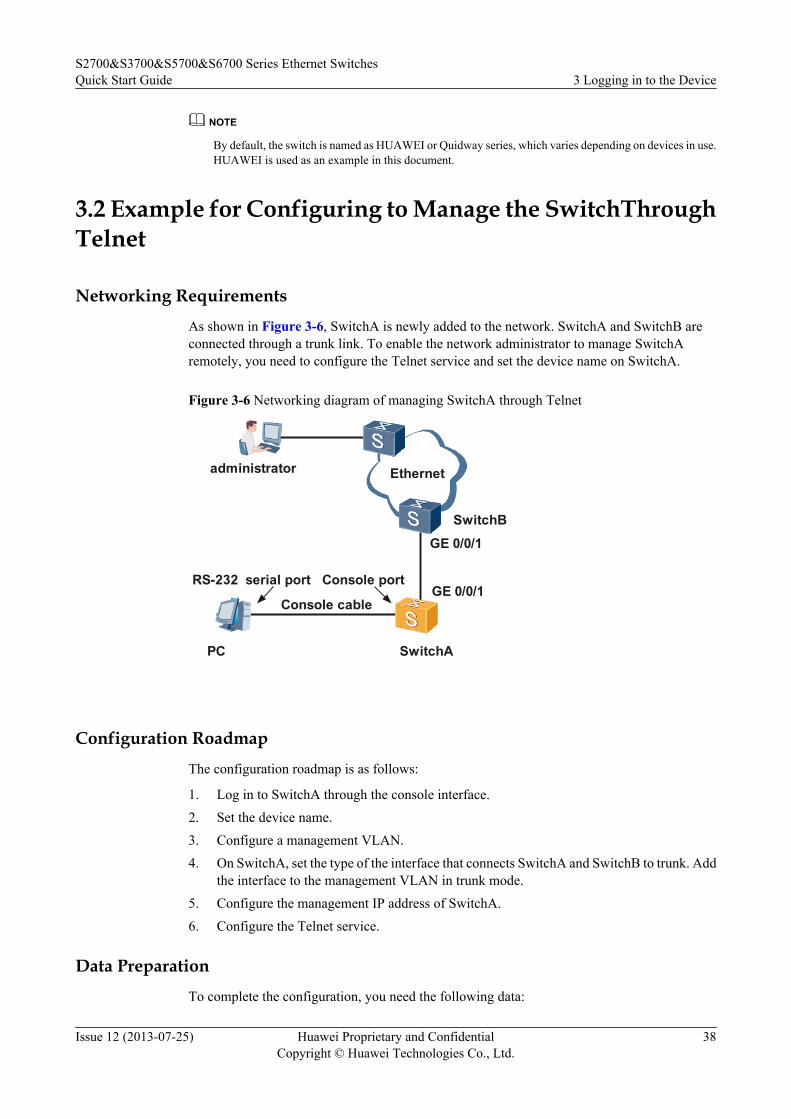
As shown in Figure 3-6, SwitchA is newly added to the network. SwitchA and SwitchB areconnected through a trunk link. To enable the network administrator to manage SwitchAremotely, you need to configure the Telnet service and set the device name on SwitchA.
Figure 3-6 Networking diagram of managing SwitchA through Telnet
RS-232
Console cable
Console port
PC SwitchA
serial port
Ethernetadministrator
SwitchB
GE 0/0/1
GE 0/0/1
Configuration Roadmap
The configuration roadmap is as follows:
1. Log in to SwitchA through the console interface.2. Set the device name.3. Configure a management VLAN.4. On SwitchA, set the type of the interface that connects SwitchA and SwitchB to trunk. Add
the interface to the management VLAN in trunk mode.5. Configure the management IP address of SwitchA.6. Configure the Telnet service.
Data Preparation
To complete the configuration, you need the following data:
S2700&S3700&S5700&S6700 Series Ethernet SwitchesQuick Start Guide 3 Logging in to the Device
Issue 12 (2013-07-25) Huawei Proprietary and ConfidentialCopyright © Huawei Technologies Co., Ltd.
38

l ID of the management VLANl Management IP address of SwitchAl Number of the interface that connects SwitchA and SwitchB on SwitchAl Authentication mode, user name, and password
Configuration Procedure1. Log in to SwitchA through the console port. For details, see Logging In to the Switch
Through the Console Interface.2. Set the device name of SwitchA.
<HUAWEI> system-view[HUAWEI] sysname SwitchA
3. Configure a management VLAN.[SwitchA] vlan 1[SwitchA-vlan1] description admin_VLAN
4. On SwitchA, set the type of the interface that connects SwitchA and SwitchB to trunk. Addthe interface to the management VLAN in trunk mode.[SwitchA] interface Gigabitethernet 0/0/1[SwitchA-GigabitEthernet0/0/1] port link-type trunk[SwitchA-GigabitEthernet0/0/1] port trunk allow-pass vlan 1[SwitchA-GigabitEthernet0/0/1] quit
5. Configure the management IP address of SwitchA.[SwitchA] interface vlanif 1[SwitchA-Vlanif1] ip address 10.10.10.10 255.255.255.0[SwitchA-Vlanif1] quit
6. Configure the Telnet service on SwitchA:l Set the authentication method to AAA, user name to huawei, and password to huawei.l Set the service type to telnet and user level to 15.l Configure AAA authentication for the users at the vty 0 to vty 4 levels.[SwitchA] aaa[SwitchA-aaa] local-user huawei password cipher huawei[SwitchA-aaa] local-user huawei service-type telnet[SwitchA-aaa] local-user huawei privilege level 15[SwitchA-aaa] quit[SwitchA] user-interface vty 0 4[SwitchA-ui-vty0-4] authentication-mode aaa [SwitchA-ui-vty0-4] return<SwitchA>
7. Verify the configuration.
NOTE
When the administrator logs in to SwitchA through Telnet, ensure that the PC of the administratorand SwitchA are reachable at the network layer.
<SwitchA> telnet 127.0.0.1Trying 127.0.0.1 ...Press CTRL+T to abortConnected to 127.0.0.1 ...************************************************************ All rights reserved (2005-2007) ** Without the owner's prior written consent, ** no decompiling or reverse-engineering shall be allowed. ** Notice: ** This is a private communication system. ** Unauthorized access or use may lead to prosecution. *
S2700&S3700&S5700&S6700 Series Ethernet SwitchesQuick Start Guide 3 Logging in to the Device
Issue 12 (2013-07-25) Huawei Proprietary and ConfidentialCopyright © Huawei Technologies Co., Ltd.
39
***********************************************************
Login authentication
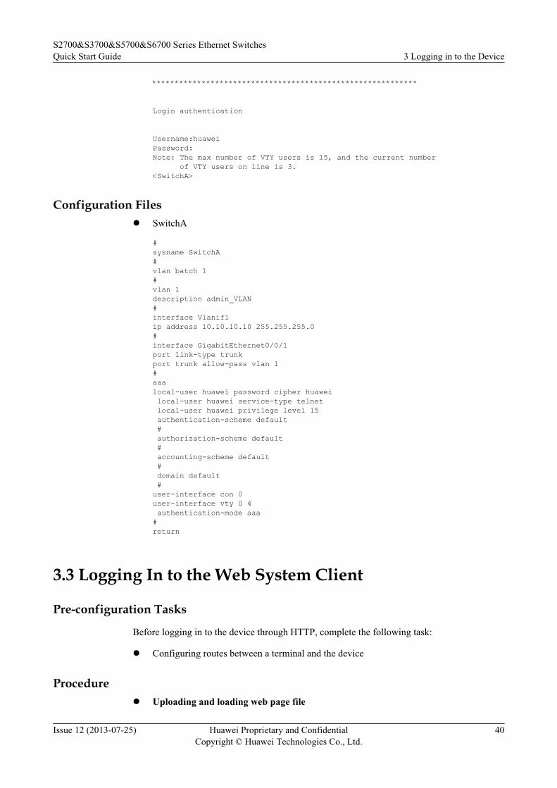
Username:huaweiPassword:Note: The max number of VTY users is 15, and the current number of VTY users on line is 3. <SwitchA>
Configuration Filesl SwitchA
#sysname SwitchA#vlan batch 1# vlan 1description admin_VLAN #interface Vlanif1ip address 10.10.10.10 255.255.255.0#interface GigabitEthernet0/0/1port link-type trunkport trunk allow-pass vlan 1#aaalocal-user huawei password cipher huawei local-user huawei service-type telnet local-user huawei privilege level 15 authentication-scheme default # authorization-scheme default # accounting-scheme default # domain default #user-interface con 0user-interface vty 0 4 authentication-mode aaa #return
3.3 Logging In to the Web System Client
Pre-configuration Tasks
Before logging in to the device through HTTP, complete the following task:
l Configuring routes between a terminal and the device
Procedurel Uploading and loading web page file
S2700&S3700&S5700&S6700 Series Ethernet SwitchesQuick Start Guide 3 Logging in to the Device
Issue 12 (2013-07-25) Huawei Proprietary and ConfidentialCopyright © Huawei Technologies Co., Ltd.
40

NOTE
The web page file have been saved on the device before delivery, so you do not need to upload thisfile when using the device for the first time. (You still need to load the file). When the device isupgraded, upload the web page file to the device again.
To obtain the Web page file of the device, log in to http://support.huawei.com/enterprise, and thenchoose Software > Product Software > Enterprise Networking > Switch > Campus Switch.Download the software package based on the product name and version. The Web page file iscontained in the software package. The file name is Product Name - the Version of Software.theVersion of Web page file.web.7z.
Table 3-2 Uploading and loading the web page file
Operation Command Description
Upload the webpage file. -
You can use FTP or TFTP to uploadthe web page file. For details, seeConfiguration Guide - BasicConfiguration File Management.
Enter thesystem view. system-view -
Load the webpage file. http server load file-name file-name specifies the name of the
web page file to be loaded.
l Configuring the HTTP service
Table 3-3 Configuring the HTTP service
Operation Command Description
Enter thesystem view. system-view -
Enable theHTTPSservice.
http secure-server enable
NOTE
l The HTTPS service must beenabled before the HTTP service.
l If the web page file are not loadedor fail to be uploaded, the systemdisplays a message indicating thatthe HTTPS service fails to beenabled.
Enable theHTTP service. http server enable -
l Logging in to the device through HTTP
1. Open the web browser on the PC, enter the http://IP, and press Enter to display theLogin page. (Ensure that the PC and device have a reachable route to each other.)Enter the web user name, password, and verification code, and select a language forthe web system, as shown in Figure 3-7. The HTTPS login URL is displayed in theaddress box, indicating that the system has gone to the HTTPS login page.
S2700&S3700&S5700&S6700 Series Ethernet SwitchesQuick Start Guide 3 Logging in to the Device
Issue 12 (2013-07-25) Huawei Proprietary and ConfidentialCopyright © Huawei Technologies Co., Ltd.
41

Figure 3-7 Login page
NOTE
In V200R003C00, the switch provides a default local user account, with the user nameadmin and password [email protected]. The default password is admin in earlier versions,and the switch retains this password after upgrading from an earlier version to V200R003C00.
You can also enter https://IP address in the address box to log in through HTTPS. HTTPSensures security of login information during login and security of data exchanged duringsubsequent operations.
2. Click Login or press Enter. The web system home page is displayed. The HTTP URLis displayed in the address box, indicating that the system has returned to the HTTPpage.You can manage and maintain the device after logging in to the web system. Fordetails, see the Web System Guide.
----End
S2700&S3700&S5700&S6700 Series Ethernet SwitchesQuick Start Guide 3 Logging in to the Device
Issue 12 (2013-07-25) Huawei Proprietary and ConfidentialCopyright © Huawei Technologies Co., Ltd.
42
4 Service Deployment
This section describes service deployment.
For details on service deployment, see the corresponding configuration guides.
S2700&S3700&S5700&S6700 Series Ethernet SwitchesQuick Start Guide 4 Service Deployment
Issue 12 (2013-07-25) Huawei Proprietary and ConfidentialCopyright © Huawei Technologies Co., Ltd.
43
5 Where to Obtain Documentation
You can obtain product documentation, online help, and release documents in various ways.
Product Documents
Table 5-1 shows how to obtain product documents.
Table 5-1 Obtaining product documents
Phase How to Obtain Documentation
HedEx Library Single Electronic Document
Installation l From http://enterprise.huawei.com
l From the local Huaweirepresentative office
l From http://enterprise.huawei.com
Version upgrade
NOTE
l Obtain the product documents from http://enterprise.huawei.com by choosing SUPPORT > ProductSupport > Enterprise Networking >Switch > Campus Switches.
Online Help
The online help is integrated and released with the product software. You can view the onlinehelp by:
l Selecting Help on the NMS interface
l Pressing F1 on any interface of the NMS
Release Documents
Release documents are released with the software package. You can visit http://enterprise.huawei.com or contact Huawei engineers.
S2700&S3700&S5700&S6700 Series Ethernet SwitchesQuick Start Guide 5 Where to Obtain Documentation
Issue 12 (2013-07-25) Huawei Proprietary and ConfidentialCopyright © Huawei Technologies Co., Ltd.
44
How to Obtain Technical SupportDuring the equipment operation and maintenance, if a fault occurs and is difficult to locate orrectify, or if you cannot rectify the fault by referring to the after-sales customer documentation,contact Huawei Customer Service Center to obtain technical support.
l Address:Huawei IndustrialBase Bantian, Longgang Shenzhen 518129People's Republic of China
l Enterprise network technical bulletin:http://support.huawei.com/ecommunity
S2700&S3700&S5700&S6700 Series Ethernet SwitchesQuick Start Guide 5 Where to Obtain Documentation
Issue 12 (2013-07-25) Huawei Proprietary and ConfidentialCopyright © Huawei Technologies Co., Ltd.
45