QUICK REFERENCE GUIDE - Sensor Centre 300 Quick... · Matrix 300™ QUICK REFERENCE GUIDE 2 1 4...
32
Matrix 300™ QUICK REFERENCE GUIDE Figure A NOTE This manual illustrates a Stand Alone application. For other types of installations, such as ID-NET™, Fieldbus, Pass-Through, etc. and for complete reader configuration using the VisiSet™ configuration program, refer to the Matrix 300™ Reference Manual available on the mini-DVD and also downloadable at www.datalogic.com. 1 Device Class Label Bracket Mounting Holes (4) Good Read LED (green) Lens Cover Ethernet Connector No Read LED (red) Aiming System Laser Pointers Power - Serial Interfaces - I/O Connector HMI X-PRESS™ Interface Ethernet Connection LED Lens Power On LED Internal Illuminator 2 3 4 5 6 7 8 9 10 11 12 13 3 4 5 7 10 11 9 8 6 13 12 1 2 2 Connector block rotates to 90° position
Transcript of QUICK REFERENCE GUIDE - Sensor Centre 300 Quick... · Matrix 300™ QUICK REFERENCE GUIDE 2 1 4...

Matrix 300™
QUICK REFERENCE GUIDE
Figure A
NOTE
This manual illustrates a Stand Alone application. For other types of installations, such as ID-NET™, Fieldbus, Pass-Through, etc. and for complete reader configuration using the VisiSet™ configuration program, refer to the Matrix 300™ Reference Manual available on the mini-DVD and also downloadable at www.datalogic.com.
1 Device Class Label
Bracket Mounting Holes (4)
Good Read LED (green)
Lens Cover
Ethernet Connector
No Read LED (red)
Aiming System Laser Pointers
Power - Serial Interfaces - I/O Connector
HMI X-PRESS™ Interface
Ethernet Connection LED
Lens
Power On LED
Internal Illuminator
2
3
4
5
6
7
8
9
10
11
12
13
3
4 5
7 10
11
9 8
6
13 12
1
2 2
Connector block rotates
to 90° position

MATRIX 300™ QUICK GUIDE
2
SUPPORT THROUGH THE WEBSITE Datalogic provides several services as well as technical support through its website. Log on to www.datalogic.com and click on the Industrial Automation links for further information:
Products - Industrial Automation - Identification
Select your product from the links on the Identification page. The product page describes specific Info, Features, Applications, Models, Accessories, and Downloads including documentation, software drivers, and the VisiSet™ utility program, which allows device configuration using a PC through Serial and Ethernet interfaces.
Support & Services - Industrial Automation
Several links from the Industrial Automation list take you to additional services such as: Service Program which contains Maintenance Agreements and Warranty Extensions; Repair Centers; On-Line RMA Return Material Authorizations; Technical Support through email or phone, Partner Program; Downloads for additional downloads.
LEGAL NOTICES © 2013 Datalogic Automation S.r.l. ALL RIGHTS RESERVED. Protected to the fullest extent under U.S. and international laws. Copying, or altering of this document is prohibited without express written consent from Datalogic Automation S.r.l.
Datalogic and the Datalogic logo are registered trademarks of Datalogic S.p.A. in many countries, including the U.S.A. and the E.U.
Matrix 300, ID-NET, VisiSet and X-PRESS are trademarks of Datalogic Automation S.r.l. All other brand and product names mentioned herein are for identification purposes only and may be trademarks or registered trademarks of their respective owners.
Datalogic shall not be liable for technical or editorial errors or omissions contained herein, nor for incidental or consequential damages resulting from the use of this material.

MATRIX 300™ QUICK GUIDE
3
STEP 1 – CONNECT THE SYSTEM To connect the system in a Stand Alone configuration, you need the hardware indicated in Figure 1. In this layout the data is transmitted to the Host on the main serial interface. Data can also be transmitted on the RS232 auxiliary interface independently from the main interface selection. When One Shot or Phase Mode Operating mode is used, the reader is activated by an External Trigger (photoelectric sensor) when the object enters its reading zone.
Figure 1 – Matrix 300™ in Stand Alone Layout
CBX100/CBX500 Pinout for Matrix 300™
The table below gives the pinout of the CBX100/CBX500 terminal block connectors. Use this pinout when the Matrix 300™ reader is connected by means of the CBX100/CBX500:
Matrix 300™
Host PG 6000
Main Serial Interface (RS232 or RS485/422 Full-Duplex)
External Trigger (for One Shot or Phase Mode)
CBX
I/O, AUX
1
2
CAB-DSxx

MATRIX 300™ QUICK GUIDE
4
CBX100/500 Terminal Block Connectors
Power Outputs
Vdc Power Supply Input Voltage + +V Power Source - Outputs
GND Power Supply Input Voltage - -V Power Reference - Outputs
Earth Protection Earth Ground O1+ Output 1 +
O1- Output 1 -
Inputs O2+ Output 2 +
+V Power Source – External Trigger O2- Output 2 -
I1A External Trigger A (polarity insensitive) O3A Output 3 (CBX500 only)
I1B External Trigger B (polarity insensitive) Auxiliary Interface
-V Power Reference – External Trigger TX Auxiliary Interface TX
+V Power Source – Inputs RX Auxiliary Interface RX
I2A Input 2 A (polarity insensitive) SGND Auxiliary Interface Reference
I2B Input 2 B (polarity insensitive) ID-NET™
-V Power Reference – Inputs REF Network Reference
Shield ID+ ID-NET™ network +
Shield Network Cable Shield ID- ID-NET™ network -
Main Interface
RS232 RS485/422 Full-Duplex
TX TX+
RTS TX-
RX * RX+
CTS * RX-
SGND SGND
* Do not leave floating, see Reference Manual for connection details.
CAUTION
Do not connect GND, SGND and REF to different (external) ground references. GND, SGND and REF
are internally connected through filtering circuitry which can be permanently damaged if subjected to voltage drops over 0.8 Vdc.

MATRIX 300™ QUICK GUIDE
5
STEP 2 – MOUNT AND POSITION THE READER 1. To mount the Matrix 300™, use the mounting bracket to obtain the most suitable position for the reader. The most common mounting
configuration is shown in the figure below.
Figure 2 –Positioning with Mounting Bracket
Tilt
Pitch

MATRIX 300™ QUICK GUIDE
6
2. When mounting the Matrix 300™ take into consideration these three ideal label position angles: Pitch or Skew 10° to 20° and Tilt 0°, although
the reader can read a code at any tilt angle provided the code fits into the Field Of View (FOV).
Figure 3 – Pitch, Tilt and Skew Angles
3. Refer to the Reading Diagrams in the Appendix of this Quick Reference Guide to determine the distance your reader should be positioned at. Further diagrams are provided in the Matrix 300™ Reference Manual.
NOTE
Rapid Configuration of the Matrix 300™ reader can be made either through the X-PRESS™ interface (steps 3-4) which requires no PC connection, or by using the VisiSet™ Setup Wizard (steps 5-6). Select the procedure according to your needs.
Pitch
Minimize
No Pitch, Tilt or Skew
Tilt
any angle
inside FOV
Skew
Assure at least 10°
FOVH
FOVV

MATRIX 300™ QUICK GUIDE
7
STEP 3 – AIM AND AUTOFOCUS THE READER (Liquid Lens Models only) Matrix 300™ provides a built-in laser pointer aiming system to aid reader positioning. For Liquid Lens models the autofocus feature is also incorporated into this function. The aiming system is accessed through the X-PRESS™ Interface. 1. Power the reader on. During the reader startup (reset or restart phase), all the LEDs blink
for one second. On the reverse side of the reader near the bracket, the “POWER ON” LED (blue) indicates the reader is correctly powered.
2. Place the Grade A Barcode Test Chart in front of the reader at the correct reading
distance for your application. See the Reading Diagrams in the Appendix of this Quick Reference Guide or in the Reference Manual.
3. Enter the Aim/Autofocus function by pressing and holding the X-PRESS™ push button until the Aim LED is on.
Figure 4 – X-PRESS™ Interface: Aim/Autofocus Function
4. Release the button to enter the Aim function. The laser pointers turn on, and the Autofocus procedure begins, see Figure 4. The Aim LED will blink until the procedure is completed.
Within 3 seconds (before the reader flashes), center one of the larger codes on the aiming system pointers (the code must not move during this procedure).
The Autofocus procedure ends when the Reading Distance and PPI values are successfully saved in the reader memory, the Aim LED will stop blinking and Matrix 300™ emits 3 high pitched beeps.
If the Autofocus cannot be reached after a timeout of about 3 (three) minutes Matrix 300™ will exit without saving the parameters to memory, the Aim LED will stop blinking and in this case Matrix 300™ emits a long low pitched beep.
You can exit the Aim/Autofocus function at any time by pressing the X-PRESS™ push button once. After a short delay the autofocus procedure is cancelled and the laser pointers turn off.

MATRIX 300™ QUICK GUIDE
8
STEP 4 – X-PRESS™ CONFIGURATION Once Matrix 300™ has focused at the correct reading distance, you must configure it for optimal code reading relative to your application. This configuration can be performed either through the X-PRESS™ Interface or the VisiSet™ configuration program.
AIM
1. Enter the Aim function by pressing and holding the X-PRESS™ push button until the Aim LED is on.
2. Release the button to enter the Aim function. The laser pointers turn on.
3. Select a single code from your application. Position the code at the center of the FOV (equidistant from the laser pointers).
The reader may start flashing and try to perform autofocus however this will have no effect on the application specific code; it can be ignored.
Figure 5 – X-PRESS™ Interface: Aim Function
Exit the Aim function by pressing the X-PRESS™ push button once. After a short delay the Aim function is cancelled and the laser pointers turn off.
SETUP
4. Enter the Setup function by pressing and holding the X-PRESS™ push button until the Setup LED is on.
5. Release the button to enter the Setup function. The Setup LED will blink until the procedure is completed.
The Setup procedure ends when the Image Acquisition parameters are successfully saved in the reader memory, the Setup LED will stop blinking and Matrix 300™ emits 3 high pitched beeps.
Figure 6 – X-PRESS™ Interface: Setup Function
If the calibration cannot be reached after a timeout of about 5 (five) seconds Matrix 300™ will exit without saving the parameters to memory, the Setup LED will stop blinking and in this case Matrix 300™ emits a long low pitched beep.

MATRIX 300™ QUICK GUIDE
9
LEARN
6. Enter the Learn function by pressing and holding the X-PRESS™ push button until the Learn LED is on.
7. Release the button to enter the Learn function. The Learn LED will blink until the procedure is completed.
The Learn procedure ends when the Image Processing and Decoding parameters are successfully saved in the reader memory, the Green Spot is activated, the Learn LED will stop blinking and
Matrix 300™ emits 3 high pitched beeps1.
Figure 7 – X-PRESS™ Interface: Learn Function
If the autolearning cannot be reached after a timeout of about 3 (three) minutes Matrix 300™ will exit without saving the parameters to memory, the Learn LED will stop blinking and in this case Matrix 300™ emits a long low pitched beep.
You can exit the Learn function at any time by pressing the X-PRESS™ push button once. After a short delay the Learn procedure is cancelled.
The Grade A Barcode Test Chart cannot be used to set the Code 128 symbology (even though the reader successfully reads the code). Use the application specific code if you need to set this symbology.
If you have used this procedure to configure Matrix 300™ go to step 7.
RESET READER TO FACTORY DEFAULT (OPTIONAL)
If it ever becomes necessary to reset the reader to the factory default values, you can perform this procedure by holding the X-PRESS™ push button pressed while powering up the reader. You must keep the X-PRESS™ push button pressed until the power up sequence is completed (several seconds) and all LEDs blink simultaneously 3 times.
All LEDs remain on for about 1 second, then off for one second, the Configuration and Environmental parameters are reset, and the status LED remains on. If connected through a CBX500 with display module, the message "Default Set" is shown on the display.
1 The Learn procedure will not recognize Pharmacode symbologies.

MATRIX 300™ QUICK GUIDE
10
STEP 5 – INSTALLING VISISET™ CONFIGURATION PROGRAM VisiSet
™ is a Datalogic reader configuration tool providing several important advantages:
Setup Wizard for rapid configuration and new users;
Defined configuration directly stored in the reader;
Communication protocol independent from the physical interface allowing the reader to be considered as a remote object to be configured and monitored.
To install VisiSet™, turn on the PC that will be used for the configuration, running Windows 98, 2000/NT, XP, Vista, 7 or 8; then insert the VisiSet™ Mini-DVD, wait for the DVD to autorun and follow the installation procedure.
This configuration procedure assumes a laptop computer, running VisiSet™, is connected to the reader's auxiliary port. The reader can also be connected to VisiSet™ through the on-board Ethernet by following the procedure in the Reference Manual.
After installing and running the VisiSet™ software program the following window appears:
Set the communication parameters from the "Options" menu. Then select "Connect", the following window appears:
Figure 8 - VisiSet™ Opening Window Figure 9 - VisiSet™ Main Window After Connection

MATRIX 300™ QUICK GUIDE
11
STEP 6 – CONFIGURATION USING SETUP WIZARD The Setup Wizard option is advised for rapid configuration or for new users. It allows reader configuration in a few easy steps. 1. Select the Setup Wizard button from the Main menu.

MATRIX 300™ QUICK GUIDE
12
2. Place the Grade A Barcode Test Chart in front of the reader at the correct reading distance for your application. See “STEP 2 - Mount
and Position the Reader” and the Reading Diagrams in the Appendix of this Quick Reference Guide or in the Reference Manual. 3. Press the "Positioning" button. The reader continuously acquires images and gives visual feedback in the view image window. The
Setup Wizard now shows four delimiters (red points) in the acquired images which indicate the region in which the calibration algorithm is active. Choose one of the larger codes and move either the reader or code to center it. The code must be aligned across the X-axis reference line at the center of the FOV. See figure below. Press the Positioning button again to stop positioning.
3
The Read. Dist. value is not significant until the Autofocus procedure ends
successfully.

MATRIX 300™ QUICK GUIDE
13
4. Select a Calibration Mode choice and press the "Calibrate" button. The reader flashes once acquiring the image and auto determines the best exposure and gain settings.
5. Press the "Fine Focusing" button to activate the Focus procedure.
CAUTION
For Liquid Lens models, the Fine Focusing procedure requires the Grade A Barcode Test Chart to be used; otherwise the procedure will fail.
4
5
MATRIX 300™ QUICK GUIDE
14
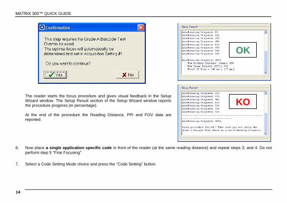
The reader starts the focus procedure and gives visual feedback in the Setup Wizard window. The Setup Result section of the Setup Wizard window reports the procedure progress (in percentage).
At the end of the procedure the Reading Distance, PPI and FOV data are reported.
6. Now place a single application specific code in front of the reader (at the same reading distance) and repeat steps 3, and 4. Do not
perform step 5 "Fine Focusing".
7. Select a Code Setting Mode choice and press the "Code Setting" button.
OK
KO
MATRIX 300™ QUICK GUIDE
15
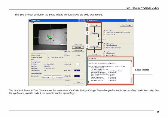
The Setup Result section of the Setup Wizard window shows the code type results.
The Grade A Barcode Test Chart cannot be used to set the Code 128 symbology (even though the reader successfully reads the code). Use the application specific code if you need to set this symbology.
Setup Result
7
4
3

MATRIX 300™ QUICK GUIDE
16
8. Select a Saving Options choice and press the "Save" button.
9. Close the Setup Wizard.
NOTE
If your application has been configured using the VisiSet™ Setup Wizard, your reader is ready. If necessary you can use VisiSet™ for advanced reader configuration.
MATRIX 300™ QUICK GUIDE
17
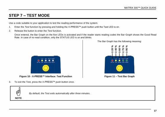
STEP 7 – TEST MODE Use a code suitable to your application to test the reading performance of the system.
1. Enter the Test function by pressing and holding the X-PRESS™ push button until the Test LED is on.
2. Release the button to enter the Test function.
Once entered, the Bar Graph on the five LEDs is activated and if the reader starts reading codes the Bar-Graph shows the Good Read Rate. In case of no read condition, only the STATUS LED is on and blinks.
The Bar Graph has the following meaning:
Figure 10 - X-PRESS™ Interface: Test Function Figure 11 – Test Bar Graph
3. To exit the Test, press the X-PRESS™ push button once.
NOTE
By default, the Test exits automatically after three minutes.
≥ 2
0 %
≥ 4
0 %
≥ 6
0 %
≥ 7
5 %
≥ 9
5 %

MATRIX 300™ QUICK GUIDE
18
ADVANCED READER CONFIGURATION For further details on advanced product configuration, refer to the complete Reference Manual on the installation Mini-DVD or downloadable at www.datalogic.com.
The following are alternative or advanced reader configuration methods.
ADVANCED CONFIGURATION USING VISISET™ Advanced configuration can be performed through the VisiSet™ program by selecting Device> Get Configuration From Temporary Memory to open the Parameter Setup window in off-line mode. Advanced configuration is addressed to expert users being able to complete a detailed reader configuration. The desired parameters can be defined in the various folders of the Parameter Setup window and then sent to the reader memory (either Temporary or Permanent):
Figure 12 - VisiSet™ Parameter Setup Window

MATRIX 300™ QUICK GUIDE
19
HOST MODE PROGRAMMING The reader can also be configured from a host computer using the Host Mode programming procedure, by commands via the serial interface. See the Host Mode Programming file on the Mini-DVD.
ALTERNATIVE LAYOUTS If you need to install an Ethernet network, ID-NET™ network, or Fieldbus network, refer to the Matrix 300™ Reference Manual. The reader can also be setup for alternative layouts by reading programming barcodes. See the "Setup Procedure Using Programming Barcodes" printable from the Mini-DVD.

MATRIX 300™ QUICK GUIDE
20
APPENDIX X-PRESS™ is the intuitive Human Machine Interface designed to improve ease of installation and maintenance.
Status and diagnostic information are clearly presented by means of the five colored LEDs, whereas the single push button gives immediate access to the following relevant functions:
Learn to self-detect and auto-configure for reading unknown codes
Setup to perform Exposure Time and Gain calibration.
Aim/Autofocus to turn on the laser pointers to aid positioning.
Test with bar graph visualization to check static reading performance
In normal operating mode the colors and meaning of the five LEDs are illustrated in the following table:
READY (green) This LED indicates the device is ready to operate.
GOOD (green) This LED confirms successful reading.
TRIGGER (yellow) This LED indicates the status of the reading phase.
COM (yellow) This LED indicates active communication on main serial port.
STATUS (red) This LED indicates a NO READ result.
During the reader startup (reset or restart phase), all the LEDs blink for one second.

MATRIX 300™ QUICK GUIDE
21
READING FEATURES Code 128 0.25 mm (10 mils)
Measurement Conditions:
Tilt Angle: 45°
Skew Angle: 15°
See the Matrix 300™ Reference Manual for a complete list of conditions.
For applications where DOF is important, pre-configured .ini files are provided which correspond to these reading diagrams. See the Matrix 300™ Reference Manual for details.
Reading Distance
Ho
rizo
nta
l R
ea
din
g W
idth
in 0 2 4 6 8 10 12 14
0
2
4
6
-2
-4
-6 mm

MATRIX 300™ QUICK GUIDE
22
Code 128 0.30 mm (12 mils)
Measurement Conditions:
Tilt Angle: 45°
Skew Angle: 15°
See the Matrix 300™ Reference Manual for a complete list of conditions.
For applications where DOF is important, pre-configured .ini files are provided which correspond to these reading diagrams. See the Matrix 300™ Reference Manual for details.
Reading Distance
Ho
rizo
nta
l R
ea
din
g W
idth
in 0 2 4 6 8 10 12 14 16
0
2
4
6
-2
-4
-6
mm

MATRIX 300™ QUICK GUIDE
23
Data Matrix Code 0.19 mm (7.5 mils)
Measurement Conditions:
Tilt Angle: 45°
Skew Angle: 15°
See the Matrix 300™ Reference Manual for a complete list of conditions.
For applications where DOF is important, pre-configured .ini files are provided which correspond to these reading diagrams. See the Matrix 300™ Reference Manual for details.
Reading Distance
Ho
rizo
nta
l R
ea
din
g W
idth
mm in 0 1 2 3 4 5 6
0
1
2
3
-1
-2
-3

MATRIX 300™ QUICK GUIDE
24
Data Matrix Code 0.25 mm (10 mils)
Measurement Conditions:
Tilt Angle: 45°
Skew Angle: 15°
See the Matrix 300™ Reference Manual for a complete list of conditions.
For applications where DOF is important, pre-configured .ini files are provided which correspond to these reading diagrams. See the Matrix 300™ Reference Manual for details.
Reading Distance
mm
Ho
rizo
nta
l R
ea
din
g W
idth
in 0 1 2 3 4 5 6 7 8
0
1
2
4
-1
-2
-4
3
-3

MATRIX 300™ QUICK GUIDE
25
TECHNICAL FEATURES
ELECTRICAL FEATURES
Power 4x2-01x models 4x2-04x models
Supply Voltage 10 to 30 Vdc PoE Device 48 Vdc Consumption 0.7 to 0.2 A max 13 W max.
Communication Interfaces
Main - RS232 - RS485/422 full-duplex
2400 to 115200 bit/s 2400 to 115200 bit/s
Auxiliary - RS232 2400 to 115200 bit/s
ID-NET™ Up to 1MBaud
Ethernet 10/100 Mbit/s
Inputs: Input 1(External Trigger) and Input 2
Opto-coupled and polarity insensitive; (see Reference Manual for details)
Outputs: Output 1, 2 and 3 NPN or PNP short circuit protected; (see Reference Manual for details)
OPTICAL FEATURES
Image Sensor CMOS sensor with Global Shutter
Image Format SXGA (1280x1024) pixels
Frame Rate 60 frames/sec
Pitch 35°
Tilt 0° - 360°
Lens Focal Length = 9 mm; Focus Control via software
Lighting System Internal Illuminator
Aiming System Laser Pointers
LED Safety/Laser Safety (pointers) to EN 62471 / IEC 60825-1 2007
PHYSICAL FEATURES Connector position 0° Connector position 90°
Dimensions 95 x 54 x 43 mm (3.7 x 2.1 x 1.7 in.) 75 x 54 x 62 mm (3.0 x 2.1 x 2.4 in.)
Weight about 238 g. (8.4 oz.)
Material Aluminium

MATRIX 300™ QUICK GUIDE
26
ENVIRONMENTAL FEATURES
Operating Temperature 0 to 50 C (32 to 122 °F)
Storage Temperature -20 to 70 C (-4 to 158 °F)
Max. Humidity 90% non condensing
Vibration Resistance 14 mm @ 2 to 10 Hz; 1.5 mm @ 13 to 55 Hz; EN 60068-2-6 2 g @ 70 to 200 Hz; 2 hours on each axis
Bump Resistance 30g; 6 ms; EN 60068-2-29 5000 shocks on each axis
Shock Resistance 30g; 11 ms; EN 60068-2-27 3 shocks on each axis
Protection Class EN 60529 IP65/IP67 *
SOFTWARE FEATURES
Readable Code Symbologies
1-D and stacked 2-D POSTAL
PDF417 Standard and Micro PDF417
Code 128 (GS1-128)
Code 39 (Standard and Full ASCII)
Code 32
MSI
Standard 2 of 5
Matrix 2 of 5
Interleaved 2 of 5
Codabar
Code 93
Pharmacode
EAN-8/13 - UPC-A/E (including Addon 2 and Addon 5)
GS1 DataBar Family
Composite Symbologies
Data Matrix ECC 200 (Standard, GS1 and Direct Marking)
QR Code (Standard and Direct Marking)
Micro QR Code
MAXICODE
Aztec Code
Australia Post
Royal Mail 4 State Customer
Kix Code
Japan Post
PLANET
POSTNET
POSTNET (+BB)
Intelligent Mail
Swedish Post
Operating Mode ONE SHOT, CONTINUOUS, PHASE MODE
Configuration Methods X-PRESS™ Human Machine Interface Windows-based SW (VisiSet™) via serial or Ethernet link Serial Host Mode Programming sequences
Parameter Storage Permanent memory (Flash)
* when correctly connected to IP67 cables with seals.

MATRIX 300™ QUICK GUIDE
27
CODE QUALITY METRICS
Standard Supported Symbologies
ISO/IEC 16022 Data Matrix ECC 200 ISO/IEC 18004 QR Code ISO/IEC 15415 Data Matrix ECC 200, QR Code ISO/IEC 15416 Code 128, Code 39, Interleaved 2 of 5, Codabar, Code 93, EAN-8/13, UPC-A/E AS9132A Data Matrix ECC 200 AIM DPM Data Matrix ECC 200, QR Code
USER INTERFACE
LED Indicators Power, Ready, Good, Trigger, Com, Status, (Ethernet Network), Good Read (Green Spot), No Read (Red Spot)
Keypad Button configurable via VisiSet™
Beeper configurable via VisiSet™

MATRIX 300™ QUICK GUIDE
28
MECHANICAL DIMENSIONS
43
[1.6
9]
=20.5
[0.81]=
8.1
[0.3
2]
95
[3
.73
]
54
[2.13]
M4 N°4
=36
[1.42]=
75
[2.9
5]
37.5
[1.4
8]
36
[1.4
2]
29.5
[1.1
6]
54
[2.12]
20.5
[0.81]==
62
[2.4
5]
7.3
[0.2
9]
43
[1.69]
75
[2.9
5] 3
6
[1.4
2]
29
.5
[1.1
6]
36
[1.42]= =
M4 n°4
37
.5
[1.4
8]
OPTICAL AXES
mm
[in]
OPTICAL AXES
Matrix 300™ Overall Dimensions
0° and 90° Solutions
Connector block rotates
to 90° position

MATRIX 300™ QUICK GUIDE
29
Figure 13 – Mounting Brackets Overall Dimensions
3
[0.1
2]
17.7
[0.7
0]
36
[1.4
2]
47
[1.8
5]
17.7
[0.70]
36
[1.42]
47
[1.85]
M 4 N°5
40
[1.5
7]
60
[2.3
6]
3
[0.1
2]
36
[1.4
2] 23
[0.9
1]
Ø4.5
[Ø0.18]
Ø8.2
[Ø0.32]
90°
47
[1.85]
90°
4.5
[0.18]
4.5
[0.18]
30°
mm
[in]

MATRIX 300™ QUICK GUIDE
30
PATENTS This product is covered by one or more of the following patents:
Utility patents: US6,512,218 B1; US6,616,039 B1; US6,808,114 B1; US6,997,385 B2; US7,053,954 B1; US7,387,246 B2; US8,058,600 B2; EP996,284 B1; EP999,514 B1; EP1,014,292 B1; EP1,128,315 B1; EP1,396,811 B1; EP1,413,971 B1; JP4,435,343 B2; JP4,571,258 B2.
Additional patents pending.
COMPLIANCE See the Matrix 300™ Reference Manual for the Declaration of Conformity. For installation, use and maintenance it is not necessary to open the reader. Only connect Ethernet and dataport connections to a network which has routing only within the plant or building and no routing outside the plant or building.
EMC COMPLIANCE In order to meet the EMC requirements:
connect reader chassis to the plant earth ground by means of a flat copper braid shorter than 100 mm;
connect pin "Earth" of the CBX connection box to a good Earth Ground;
for direct connections, connect your cable shield to the locking ring nut of the connector

MATRIX 300™ QUICK GUIDE
31
POWER SUPPLY This product is intended to be installed by Qualified Personnel only.
This product is intended to be connected to a UL Listed Computer (LPS or “Class 2”) which supplies power directly to the reader, or a UL Listed Direct Plug-in Power Unit (rated 10 to 30 V, minimum 1 A) marked LPS or “Class 2”, or Power over Ethernet source Device supplied by UL Listed Direct Plug-in Power Unit marked LPS or “Class 2”.
CE COMPLIANCE Warning: This is a Class A product. In a domestic environment this product may cause radio interference in which case the user may be required to take adequate measures.
LASER SAFETY The Matrix 300™ internal illuminators contain two aiming Laser LEDs used to position the reader. Therefore the product is classified as a Class 2 laser product according to IEC 60825-1 regulations and as a Class II laser product according to CDRH regulations. Disconnect the power supply when opening the device during maintenance or installation to avoid exposure to hazardous laser light. The laser beam can be switched on or off through a software command.
LED SAFETY LED emission according to EN 62471.

MATRIX 300™ QUICK GUIDE
32
FCC COMPLIANCE Modifications or changes to this equipment without the expressed written approval of Datalogic could void the authority to use the equipment.
This device complies with PART 15 of the FCC Rules. Operation is subject to the following two conditions: (1) This device may not cause harmful interference, and (2) this device must accept any interference received, including interference which may cause undesired operation.
This equipment has been tested and found to comply with the limits for a Class A digital device, pursuant to part 15 of the FCC Rules. These limits are designed to provide reasonable protection against harmful interference when the equipment is operated in a commercial environment. This equipment generates, uses, and can radiate radio frequency energy and, if not installed and used in accordance with the instruction manual, may cause harmful interference to radio communications. Operation of this equipment in a residential area is likely to cause harmful interference in which case the user will be required to correct the interference at his own expense.
821002360