Quasi-Optical Designael.chungbuk.ac.kr/ref-2/antenna/antenna-design/maxwell-cox(ppt... · This is...
28
Quasi-Optical Design A Short Tutorial ….. CEOI Training Workshop Passive Microwave STFS RAL, 9th November 2012 Dr Graham Maxwell-Cox Astrium Ltd, Portsmouth CEOI Workshop QO Design Presentation 091112.pptx
Transcript of Quasi-Optical Designael.chungbuk.ac.kr/ref-2/antenna/antenna-design/maxwell-cox(ppt... · This is...

Quasi-Optical Design A Short Tutorial …..
CEOI Training Workshop
Passive Microwave STFS RAL, 9th November 2012
Dr Graham Maxwell-Cox
Astrium Ltd, Portsmouth
CEOI Workshop QO Design Presentation 091112.pptx
Design In-sight
What is Quasi-Optical (QO) Design / Analysis?
– Complimentary mixture of Optical and Microwave
design
– Applicable in the THz region (0.01 -1 THz) !
– A means of visualising the feed system in a microwave
radiometer (microwaves aren’t generally visible …)
– The basis of a design of a microwave radiometer
system before MW field analysis
– A means of analysing the radiometer performance
09/11/12
CEOI Workshop QO Design.ppt Graham Maxwell-Cox, Astrium Ltd Page 2

Quasi-Optics?
Straw Cutter Lite ! (2007)
• Demonstrates the microwave system built on CEOI Straw Cutter program
for STEAM-R using light sources and multi-focus system
• Note the Beam splitting 09/11/12
CEOI Workshop QO Design.ppt Graham Maxwell-Cox, Astrium Ltd Page 3
KEY
Base Plate Hobbycraft
Mirrors (adjustable) Hobbycraft
Lenses B&Q
LED Array B&Q
Roof Mirror Tesco (Alcan)
Detector Planes Ryman
Optical Support Habitat
Adhesives WH Smith

Focus of Attention
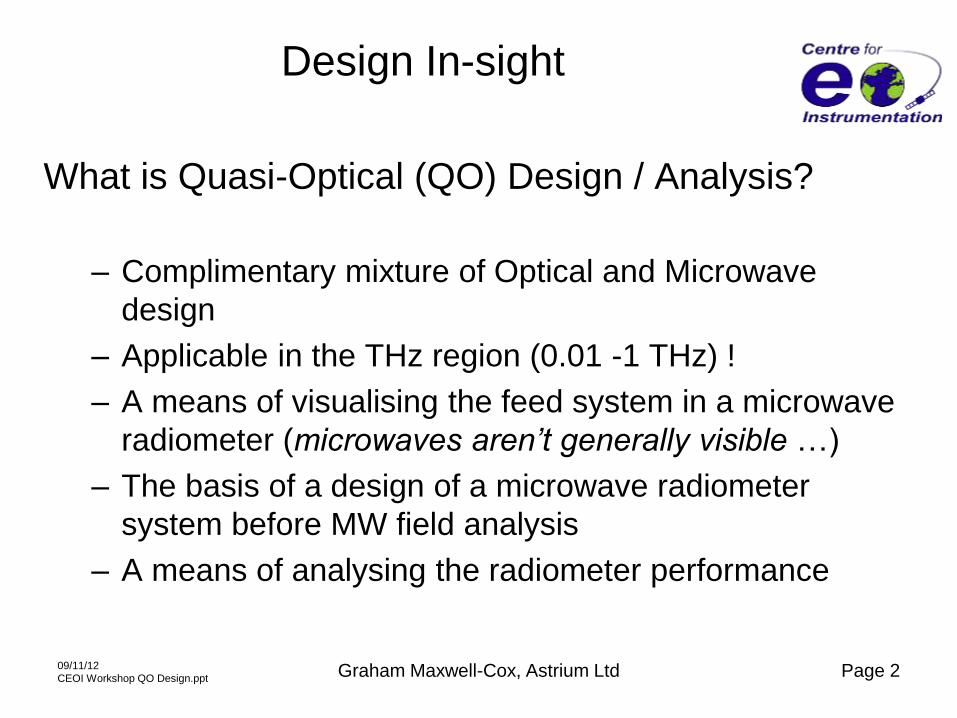
• Context: Microwave Radiometers for Space
– e.g. AMSU-B, MHS and now Eumetsat MetOp –SG MWS, MWI and ICI
• Requirements
– Footprint on ground
• Extent in km depends on satellite height
• Pattern angle (1º- 5º from LEO)
– Frequency bands and channels needed
• 23 - 229 GHz (for MWS) 10:1 frequency ratio !
– Radiometer sensitivity defined and leading to requirements on:-
• RF Losses in feed system
– Ohmic losses in components (current flow in surfaces)
– Spillover losses (field levels outside components)
– Reflection and scattering losses (edges and corners of
components)
09/11/12
CEOI Workshop QO Design.ppt Graham Maxwell-Cox, Astrium Ltd Page 4
MetOp–SG Radiometers
09/11/12
CEOI Workshop QO Design.ppt Graham Maxwell-Cox, Astrium Ltd Page 5

Design Approach
• Main Mirror (reflector) defines footprint
– Mirror will generally be scanned
• Reflector geometry (Parabolic, spherical) defines :
– focal length (position of feed system)
– cross-polar radiation (polarisation purity)
• QO chain to the Mirror defines illumination properties of
the reflector
– Beam size and foot print
– Sidelobe levels and beam efficiency
– In addition shares focal region with multiple feeds
09/11/12
CEOI Workshop QO Design.ppt Graham Maxwell-Cox, Astrium Ltd Page 6

Function of QO network
• Basic functions of the Quasi-Optical Network (QON)
• The QON design needs to translate beamwaist at the
shared common focus of the Main Reflector to each feed
horn in each band
• The beamwaist may be magnified or diminished by the
optics to match the feed pattern
• The purity of the beam shape at the beam waist needs to
be maintained to ensure the correct illumination of the
main reflector and the farfield pattern performance
(ground footprint)
09/11/12
CEOI Workshop QO Design.ppt Graham Maxwell-Cox, Astrium Ltd Page 7

Field at the Focus of a reflector
• In an Optical System (where apertures are many 100’s or 1000’s of wavelengths in
extent), generally an image consisting of many points would be considered at a focal
plane. Each point in the focal plane has a finite PSF (Point Spread Function).
• In a Microwave System (of maybe 10-100 wavelengths or less), the PSF is the
image in a single beam system. This is the antenna beam, or foot print.
• Classically, in antenna system design terms, the focus would be considered as a
point where you placed your feed (with known angular pattern) to form the antenna
pattern from the reflector
• In QO, and gaussian beam optics, the focus is considered to be a finite beamwaist,
with associated radius and phase centre, defining how the field radiates from the
point.
• In QO this beamwaist is expanded round the QO system, between components (e.g.
mirrors, filters, grids, dichroics and lenses)
• This expansion can be achieved in many ways:
– Gaussian beam expansion
– Physical Optics expansion
– Ray Traced expansion
– And combinations of all of these
09/11/12
CEOI Workshop QO Design.ppt Graham Maxwell-Cox, Astrium Ltd Page 8
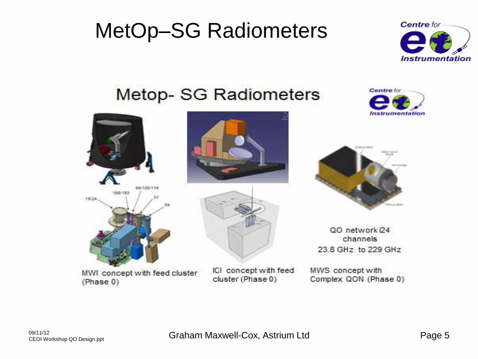
Analysis Techniques
Large range of properties can be used to analyse a QO system
• Light travels in straight lines! (Geometric Optics, GO)
• Light reflects and refracts at a surface (Snell’s Law)
• Light is an electromagnetic EM wave !
• EM Waves propagate (Huygens expansion)
• EM fields can be represented by Gaussian Beams (Single mode and multi-
mode Gaussian Beam analysis)
• EM fields in a horn feed can be represented by cylindrical modes or
spherical modes (HE11, which is a gaussian like mode)
• EM Waves are produced by currents on surfaces (Physical Optics, PO)
• Currents are induced by EM fields and reradiate (Diffraction, GTD)
Wave Particle Duality Paradox ! The QO system can be thought of in
terms of Rays or Waves
All these properties are used in QO analysis 09/11/12
CEOI Workshop QO Design.ppt Graham Maxwell-Cox, Astrium Ltd Page 9

Beam Expansion Techniques
• Geometrical Optics (GO) – Light rays in straight lines
• Non-Sequential Ray Tracing (NSRT) – Interfering multiple rays
• Gaussian Beam Expansion (GBE) -(Single mode or multimode)
• Physical Optics (PO) – Surface currents produce fields
• Geometrical Theory of Diffraction (GTD) – Induced currents
on edges expand as fields (Keller cones)
• Beam Propagation Synthesis (BPS) - Selective field expansion
around ray bundles
• Method of Moments (MOM) – Field coupling between
components
• Finite Element (FE)- expansion of current elements on complete
system
09/11/12
CEOI Workshop QO Design.ppt Graham Maxwell-Cox, Astrium Ltd Page 10
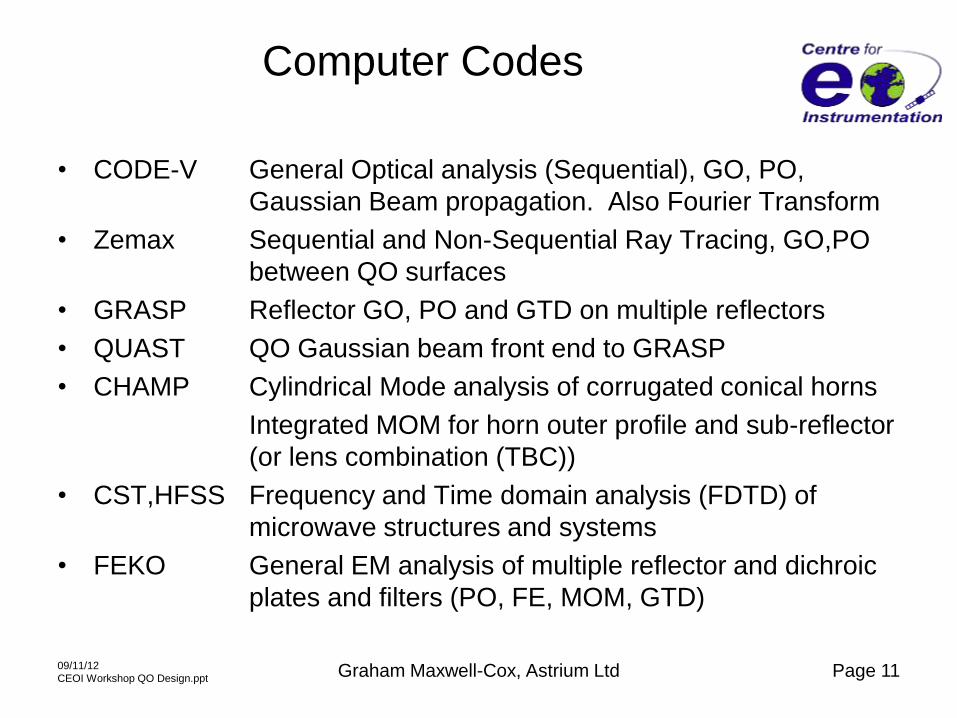
Computer Codes
• CODE-V General Optical analysis (Sequential), GO, PO,
Gaussian Beam propagation. Also Fourier Transform
• Zemax Sequential and Non-Sequential Ray Tracing, GO,PO
between QO surfaces
• GRASP Reflector GO, PO and GTD on multiple reflectors
• QUAST QO Gaussian beam front end to GRASP
• CHAMP Cylindrical Mode analysis of corrugated conical horns
Integrated MOM for horn outer profile and sub-reflector
(or lens combination (TBC))
• CST,HFSS Frequency and Time domain analysis (FDTD) of
microwave structures and systems
• FEKO General EM analysis of multiple reflector and dichroic
plates and filters (PO, FE, MOM, GTD)
09/11/12
CEOI Workshop QO Design.ppt Graham Maxwell-Cox, Astrium Ltd Page 11

Gaussian Beam Propagation
Propagation through the system
o Example from STEAM-R QO system (CEOI 340 GHz 2008)
o CODE-V mode (GO) – Source horn (bottom left) feeds main reflector via mirrors
o Sequential QO system – no multiple paths possible
o Same system with Gaussian Beam expansion from feed
o Non-Sequential Ray Tracing (NSRT, zemax) may be used to analyse this
system - multiple paths possible
09/11/12
CEOI Workshop QO Design.ppt Graham Maxwell-Cox, Astrium Ltd Page 12
11:41:18
Cross section view Scale: 0.09 GMC 19-May-08
277.78 MM
11:41:46
Straw Man Reverse Scale: 0.09 GMC 19-May-08
277.78 MM
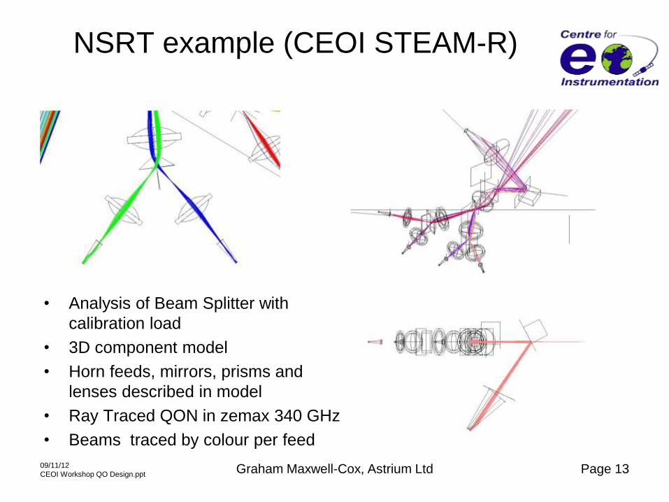
NSRT example (CEOI STEAM-R)
• Analysis of Beam Splitter with
calibration load
• 3D component model
• Horn feeds, mirrors, prisms and
lenses described in model
• Ray Traced QON in zemax 340 GHz
• Beams traced by colour per feed
09/11/12
CEOI Workshop QO Design.ppt Graham Maxwell-Cox, Astrium Ltd Page 13

Feed Horn Design
• Basic design of feed horn in QON aims
– Wide bandwidth (e.g.16% at 183 GHz needed)
– Very Good beam efficiency (low sidelobes , 1st -35 dB to -40 dB)
– Gaussian shaped beam (HE11 mode likely)
– Good polarisation Purity (good cross-polar performance <-30 dB)
– Good return loss at throat (-30 dB)
• Solution is a hybrid pattern horn
– Potter stepped horn (1% bandwidth)
– Linear or profiled Corrugated horn (20%)
– Ultra Gaussian Horn (UGH) (very low sidelobes -40 dB) but long length
– Modified profile corrugated horns (higher sidelobes, but shorter in length)
• Not essential to have a gaussian beam, and in fact horn patterns are only gaussian
shape to a given power level (typically -20 to -40 dB)
• Ultra Gaussian Horn may be characterised by a simple beamwaist near the horn
aperture and fairly constant in position (phase centre)
09/11/12
CEOI Workshop QO Design.ppt Graham Maxwell-Cox, Astrium Ltd Page 14

166/183 GHz Ultra Gaussian Horn
• 166/183 GHz corrugated horn (CEOI PMSIT development)
• High Performance Ultra Gaussian low sidelobe (-40 dB) design
• Beamwaist radius 3.7 mm 183 GHz
09/11/12
CEOI Workshop QO Design.ppt Graham Maxwell-Cox, Astrium Ltd Page 15
-60-55-50-45-40-35-30-25-20-15-10
-50
-25 -20 -15 -10 -5 0 5 10 15 20 25
Dir
ect
ivit
y d
B
Pattern Angle deg
Astrium PMSIT Horn 160-194 GHz Normalised Co-Polar and Cross-Polar
0 deg cut
160
166
172
183
194
160 xpl
166 xpl
172 xpl
183 xpl
194 xpl
Measured co-polar and cross-
polar Radiation patterns
Mirror / Reflector Design
Just a few points about mirrors !
• F/D ratio should be kept high (>0.5) long focal lengths, but
– In microwave systems a long focal length mirror leads to a large feed
horn with small pattern angle needed to feed it
– A short focal length leads to high cross-polar levels
(F/D=1, -23 dB and F/D=0.5, -17 dB)
– Beam symmetry is important for good mode matching in horn so
spherical aberration needs to be minimised
– Long focal length and illumination close to mirror normal is best
09/11/12
CEOI Workshop QO Design.ppt Graham Maxwell-Cox, Astrium Ltd Page 16
Good mirror to use is the 90º offset parabola –
no spherical aberration ! • Single focus mirror – collimated beam in
nearfield
• Surface finish <0.01λ rms (<10 microns)
• Aluminium or Gold (>1 micron) plating on
aluminium (mainly because it protects
aluminium)

Microwave Lens Design
• Standard dielectric lenses are problematic! – Use to transfer beamwaist from one place to another in QON
– Or scale the beamradius size and translate beam
– Matching attempted with quarter-wave blazing on surface
• Standing waves evident between Corrugated horn and lens due to a few
factors – Higher order modes in a simple HE11 design do not match at edge of lens
– Reflections occur between the horn rim and the lens
– Lens suffers from internal reflections and high energy (focussed regions) within the lossy
lens materials
Solutions
• Attempt to match fields in horn to a shaped lens – Analysis available (internal Astrium F) or CHAMP horn analysis (Ticra sometime soon!)
• Develop an advanced lens design with low reflectivity – Astrium CEOI Metamaterial Study (2011) and Advanced GRIN lens design (AGLeD)
(2012).
09/11/12
CEOI Workshop QO Design.ppt Graham Maxwell-Cox, Astrium Ltd Page 17

Standing Wave in Lens / Horn
• Horn-Lens-Horn coupling 340 GHz
• Optimised lens shape with blazing
• Peak field at focus of lens
• 0.7 dB ripple in standing wave along the optical axis
• ~1 dB across optical axis
09/11/12
CEOI Workshop QO Design.ppt Graham Maxwell-Cox, Astrium Ltd Page 18

MWS QON Concept
• Complex QO network from MWS
Phase A1 study for ESA
• QON includes focussing mirrors,
lenses, dichroics beam splitters,
polarisation grids and feed horns
• Main Mirror off top LHS
• Multichannel 24 GHz to 229 GHz
• Scheme is only a concept – Not
here a detailed design
• Working Zemax model available
• PO analysis of reflector and feed
system
• EM model of part of QO system
(FEKO model)
09/11/12
CEOI Workshop QO Design.ppt Graham Maxwell-Cox, Astrium Ltd Page 19
QON
input 31H
24H
54H
89V
229H
166V
D1
D2
D3
P1
L1
L2
M1
M2
D4 M5
M3
M4 183H
Diplexer
H1
H2
H6
H3
H5
H4
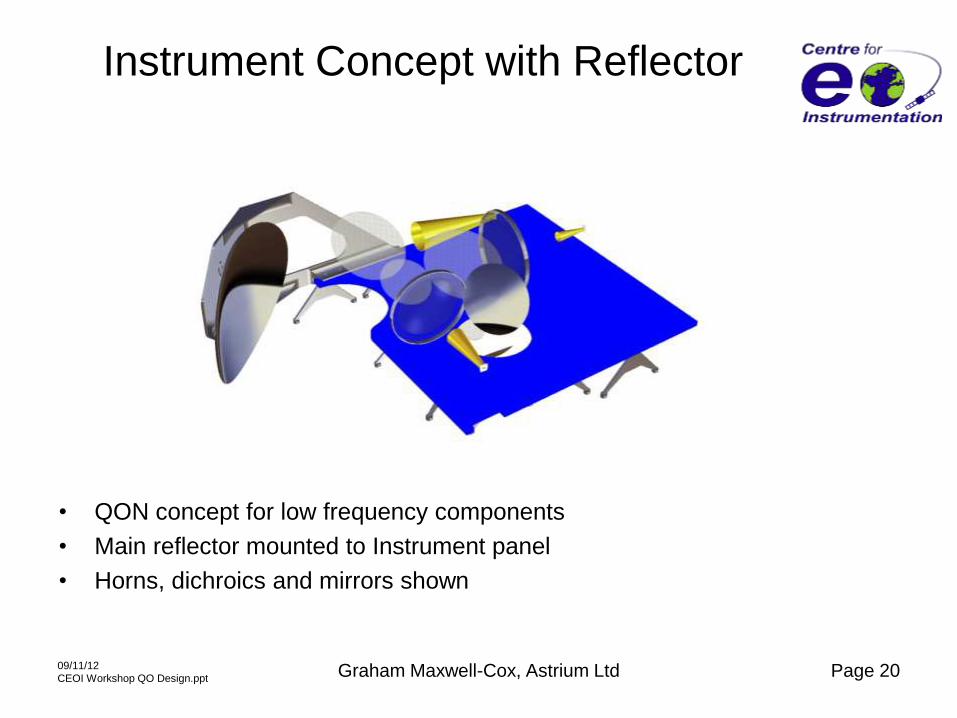
Instrument Concept with Reflector
• QON concept for low frequency components
• Main reflector mounted to Instrument panel
• Horns, dichroics and mirrors shown
09/11/12
CEOI Workshop QO Design.ppt Graham Maxwell-Cox, Astrium Ltd Page 20

Non-Sequential Ray Tracing (zemax)
• Example Ray Traced
layout using Non-
Sequential Ray Tracing
(NSRT) in zemax using
detector planes
• Multi-feed QO system off
single main reflector (off
top LHS)
• Predicted beams in QO
system at 229 GHz
• Dissimilar mirrors in
Beamwaveguide (200
and 100 mm FL)
• (a) Two orthogonal cuts
of field at Common
Focus off main reflector
system
• (b) Field magnification at
horn (x2)
09/11/12
CEOI Workshop QO Design.ppt
16/07/12 - 21
CEOI MWS ATMS New layout 2 Rad 200 35_7d 183GHz 060612.zmxConfiguration 1 of 1
3D Layout
CEOI MWS Analysis: ASTU Portsmouth GM-C06/06/2012
X
Y
Z
CEOI MWS ATMS New layout 2 Rad 200 35_7d 183GHz 060612.zmxConfiguration 1 of 1
3D Layout
CEOI MWS Analysis: ASTU Portsmouth GM-C06/06/2012
X
Y
Z
-30 -24 -18 -12 -6 0 6 12 18 24 301E-5
1E-4
1E-3
1E-2
1E-1
1E+0
X coordinate value
log Coherent Irradiance
CEOI MWS ATMS New layout 2 Rad 200 35_7e 183GHz 060612.zmxConfiguration 1 of 1
log Coherent Irradiance
CEOI MWS Analysis: ASTU Portsmouth GM-C06/06/2012Detector 99, NSCG Surface 1: 183 aperture det 0Row Center, Y = 0.0000E+000Size 60.000 W X 60.000 H Millimeters, Pixels 300 W X 300 H, Total Hits = 8950Peak Irradiance : 5.9390E-001 Watts/cm^2Total Power : 1.1280E-001 Watts
-30 -24 -18 -12 -6 0 6 12 18 24 301E-5
1E-4
1E-3
1E-2
1E-1
1E+0
Y coordinate value
log Coherent Irradiance
CEOI MWS ATMS New layout 2 Rad 200 35_7e 183GHz 060612.zmxConfiguration 1 of 1
log Coherent Irradiance
CEOI MWS Analysis: ASTU Portsmouth GM-C06/06/2012Detector 99, NSCG Surface 1: 183 aperture det 0Column Center, X = 0.0000E+000Size 60.000 W X 60.000 H Millimeters, Pixels 300 W X 300 H, Total Hits = 8950Peak Irradiance : 5.9390E-001 Watts/cm^2Total Power : 1.1280E-001 Watts
-30 -24 -18 -12 -6 0 6 12 18 24 301E-5
1E-4
1E-3
1E-2
1E-1
1E+0
Y coordinate value
log Coherent Irradiance
CEOI MWS ATMS New layout 2 Rad 200 35_7e 183GHz 060612.zmxConfiguration 1 of 1
log Coherent Irradiance
CEOI MWS Analysis: ASTU Portsmouth GM-C06/06/2012Detector 20, NSCG Surface 1: F1 Common Focus Ref surfaceColumn Center, X = 0.0000E+000Size 60.000 W X 60.000 H Millimeters, Pixels 100 W X 100 H, Total Hits = 9132Peak Irradiance : 2.7590E-001 Watts/cm^2Total Power : 1.5032E-001 Watts
-30 -24 -18 -12 -6 0 6 12 18 24 301E-5
1E-4
1E-3
1E-2
1E-1
1E+0
X coordinate value
log Coherent Irradiance
CEOI MWS ATMS New layout 2 Rad 200 35_7e 183GHz 060612.zmxConfiguration 1 of 1
log Coherent Irradiance
CEOI MWS Analysis: ASTU Portsmouth GM-C06/06/2012Detector 99, NSCG Surface 1: 183 aperture det 0Row Center, Y = 0.0000E+000Size 60.000 W X 60.000 H Millimeters, Pixels 300 W X 300 H, Total Hits = 8950Peak Irradiance : 5.9390E-001 Watts/cm^2Total Power : 1.1280E-001 Watts
-30 -24 -18 -12 -6 0 6 12 18 24 301E-5
1E-4
1E-3
1E-2
1E-1
1E+0
Y coordinate value
log Coherent Irradiance
CEOI MWS ATMS New layout 2 Rad 200 35_7e 183GHz 060612.zmxConfiguration 1 of 1
log Coherent Irradiance
CEOI MWS Analysis: ASTU Portsmouth GM-C06/06/2012Detector 99, NSCG Surface 1: 183 aperture det 0Column Center, X = 0.0000E+000Size 60.000 W X 60.000 H Millimeters, Pixels 300 W X 300 H, Total Hits = 8950Peak Irradiance : 5.9390E-001 Watts/cm^2Total Power : 1.1280E-001 Watts
(a) (b)
Graham Maxwell-Cox, Astrium Ltd
(229 GHz)
(53 GHz)

Lens Tilt effect on Beam Shape
NSRT applied to dielectric lens (53GHz) • Gaussian Source LHS (a)
• Zemax Detector planes set around lens with Huygens expansion of field
09/11/12
CEOI Workshop QO Design.ppt Graham Maxwell-Cox, Astrium Ltd Page 22
Source field on LHS modified by
reflection from lens
a) Source with No lens +0° (-40dB)
b) Lens Tilt +5° (-20 dB skirts)
c) Lens Tilt -5°
Note the Optical focus on RHS
Two other foci are on the LHS near
to and in the lens)
(b)
(c)
(a)
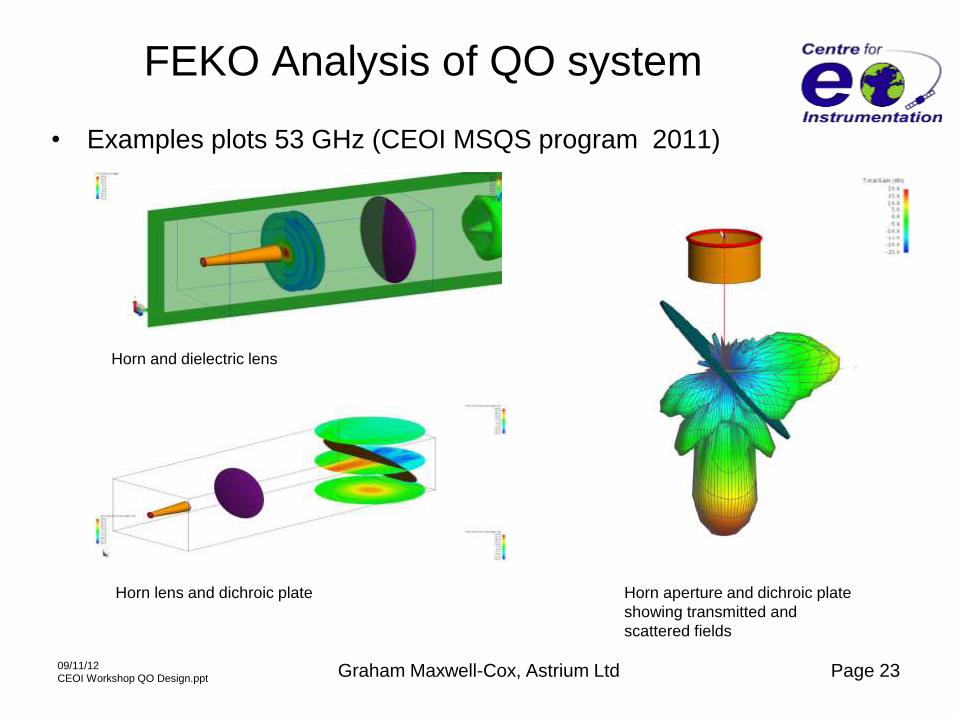
FEKO Analysis of QO system
• Examples plots 53 GHz (CEOI MSQS program 2011)
09/11/12
CEOI Workshop QO Design.ppt Graham Maxwell-Cox, Astrium Ltd Page 23
Horn and dielectric lens
Horn lens and dichroic plate Horn aperture and dichroic plate
showing transmitted and
scattered fields

QO system analysis in FEKO
• System contains a Gaussian
horn, two elliptical mirrors and
dual layer FSS
• FEKO analysis with fields
analysed on planes
• Sidelobes and scattering from
back of FSS evident
• Complementary model to
NSRT
09/11/12
CEOI Workshop QO Design.ppt Graham Maxwell-Cox, Astrium Ltd Page 24
QMUL QO system CEOI MSQS
program (54 GHz) – spin-off
Detector planes showing EM
incident and reflected fields
FEKO surface model

QO Field probe 89 GHz
09/11/12
CEOI Workshop QO Design.ppt Graham Maxwell-Cox, Astrium Ltd Page 25
• 89 GHz gaussian
beam horn mounted
on three orthogonal
micrometer driven
linear stages
• Part of TSB
Breadboard
• Horn used to sample
the beamwaist in QO
system
• 1 micron sensitivity
<1/100λ

Quasi-Optical measurements
• Optical test bench example showing fields from
horns and mirrors being measured (340 GHz) (CEOI
STEAM-R - Straw Cutter project 2008)
• Horn probe is mounted on linear adjustment base to
scan field from reflector.
• Some beam distortion can been seen in the probe
scan from edge reflection and diffraction
• TSB BB 183/229 GHz work will have 2D scans
across the beam
09/11/12
CEOI Workshop QO Design.ppt Graham Maxwell-Cox, Astrium Ltd

TSB Breadboard MWS
• TSB 166/183/229 GHz QO breadboard
• Design as per MWS Radiometer requirements
• Horn feeds on 3D micrometer stages for field probing
09/11/12
CEOI Workshop QO Design.ppt Graham Maxwell-Cox, Astrium Ltd Page 27

Main Reflector on TSB Breadboard
Initial Integration and alignment of main reflector on TSB breadboard
• 53 GHz corrugated horn may be seen in the foreground
• COTS optics supports and mirrors (Newport Spectra Physics)
• Work in progress! 09/11/12
CEOI Workshop QO Design.ppt Graham Maxwell-Cox, Astrium Ltd Page 28