Quartz Crystal
50
Transcript of Quartz Crystal
Quartz Crystals size mm frequency range page
SMD KX-327S 8,7/3,8/2,5 32,768 kHz 04
SMD KX-327L 7,0/1,5/1,4 32,768 kHz 05
SMD KX-327NHT 3,2/1,5/0,90 32,768 kHz 06
SMD KX-327XS 4,95/1,82/0,96 32,768 kHz 07
SMD KX-5 2,0/1,6/0,45 20,0 ~ 80,0 MHz 08
SMD KX-6 2,5/2,0/0,55 16,0 ~ 80,0 MHz 09
SMD KX-7 3,2/2,5/1,2 12,0 ~ 60,0 MHz 10
SMD KX-8 4,0/2,5/0,8 12,0 ~ 60,0 MHz 11
SMD KX-9A 5,0/3,2/1,0 8,0 ~ 300,0 MHz 12
SMD KX-12B 6,0/3,5/1,2 8,0 ~ 50,0 MHz 13
SMD KX-13 7,0/5,0/1,3 6,0 ~ 160,0 MHz 14
SMD KX-20 11,6/5,5/1,6 3,579545 ~ 25,0 MHz 15
SMD KX-K/KX-KS 12,3/4,5/4,2 (3,2) 3,50 ~ 70,0 MHz 16
SMD KX-C 12,5/4,6/3,7 3,50 ~ 30,0 MHz 17
Low profile HC-49/U3H KX-3H 11,35/5,0/3,50 3,20 ~ 70,0 MHz 18
HC-49/U KX-49 11,3/4,9/13,6 1,84320 ~ 200,0 MHz 19
Cylindrical types 2x6mm, 3x8mm, 3x9mm
KX-26 KX-38 KX-39 6,2/2,0 Ø – 8,0/3,0 Ø 32,768 kHz /77,50 kHz 20
Clock Oscil lators size mm frequency range page
SMD KXO-V95 2,5 ~ 3,3 Volt 2,5/2,0/0,82 1,0 ~ 70,0 MHz 21
SMD KXO-V96 2,5 ~ 3,3 Volt 3,2/2,5/1,2 1,0 ~ 133,0 MHz 22
SMD KXO-V99 1,8 ~ 3,3 Volt 5,0/3,2/1,2 1,0 ~ 200,0 MHz 23
SMD KXO-V97 1,8 ~ 3,3 Volt 7,0/5,08/1,8 1,0 ~ 160,0 MHz 24
SMD KXO-97 5,0 Volt 7,0/5,08/1,8 1,0 ~ 100,0 MHz 25
DIL 14, KXO-200, KXO-400, TTL/CMOS, Tristate 20,8/13,2/5,08 0,5 ~ 100,0 MHz 26-27
DIL 8, KXO-210, KXO-410, TTL/CMOS, Tristate 13,2/13,2/6,0 0,5 ~ 100,0 MHz 26-27
02
Clock Oscil lators size mm frequency range page
SMD VCXO KXO-75 7,0/5,0/1,70 1,544 ~ 77,760 MHz 28
SMD VCTCXO KXO-82 7,0/5,0/2,0 12,60 ~ 20,0 MHz 29
SMD VCTCXO KXO-83 5,0/3,2/1,5 12,0 ~ 26,0 MHz 30
SMD VCTCXO KXO-84 3,2/2,5/0,9 12,60 ~ 26,0 MHz 31
SMD LVDS KXO-V65 7,0/5,0/1,7 19,440 ~ 700,0 MHz 32
SMD LVDS VCXO KXO-V63 7,0/5,0/1,7 27,0 ~ 700,0 MHz 33
SMD PECL KXO-67 7,0/5,0/1,7 50,0 ~ 212,50 MHz 34
Ceramic Resonators size mm frequency range page
SMD KX-ZTT-CW MX 2,4/1,9/1,5 16,0 ~ 50,0 MHz 35
SMD KX-ZTT-CV MT/MX 3,7/3,1/1,0 8,0 ~ 50,0 MHz 36
SMD KX-ZTT-CE MG 3,2/1,3/1,0 8,0 ~ 12,0 MHz 37
SMD KX-ZTT-CR MG 4,5/2,0/1,2 4,0 ~ 8,0 MHz 38
SMD KX-ZTT-CC MG
7,4/3,4/1,8
1,84 ~ 8,0 MHz
39
SMD KX-ZTT-CS MT/MX 4,7/4,1/1,6 8,0 ~ 50,0 MHz 40
KX-ZTT series 10,0/5,5/8,0(10,0) 1,84 ~ 50,0 MHz 41
KX-ZTA series 10,0/5,0/7,5(10,0) 1,84 ~ 50,0 MHz 42
KX-ZTB series 190 ~ 1250 kHz 43
Ceramic Resonators - Precaution of Handling 44
Fi lters 45-47
Terms and Conditions of Delivery and Payment 48-49
Fax order sheet for samples free of charge 50
03
actual size
Quartz Crystal 32,768 kHz SMD-version model KX - 327S
frequency 32,768 kHz
operating temperature standard -20° ~ +70°C available -40° ~ +85°C (= KX-327ST)
frequency tolerance at +25°C
± 30 ppm standard ± 20 ppm available
temperature tolerance at -20° ~ +70°C -40° ~ +85°C
-0,034 ±0,006 ppm/°C2 typ., -0,042 ppm/°C2 max.
load capacitance CL 12,5 pF
series resonance R1 max. 50k Ohm
aging ( first year ) ± 5 ppm shunt capacitance Co max. 2 pF
drive level in mW max. 0,001 RoHS started from date code May, 2005
contents of reel 3000 pcs.
part no. 12.87110 ~ 12.87149
soldering condition
04
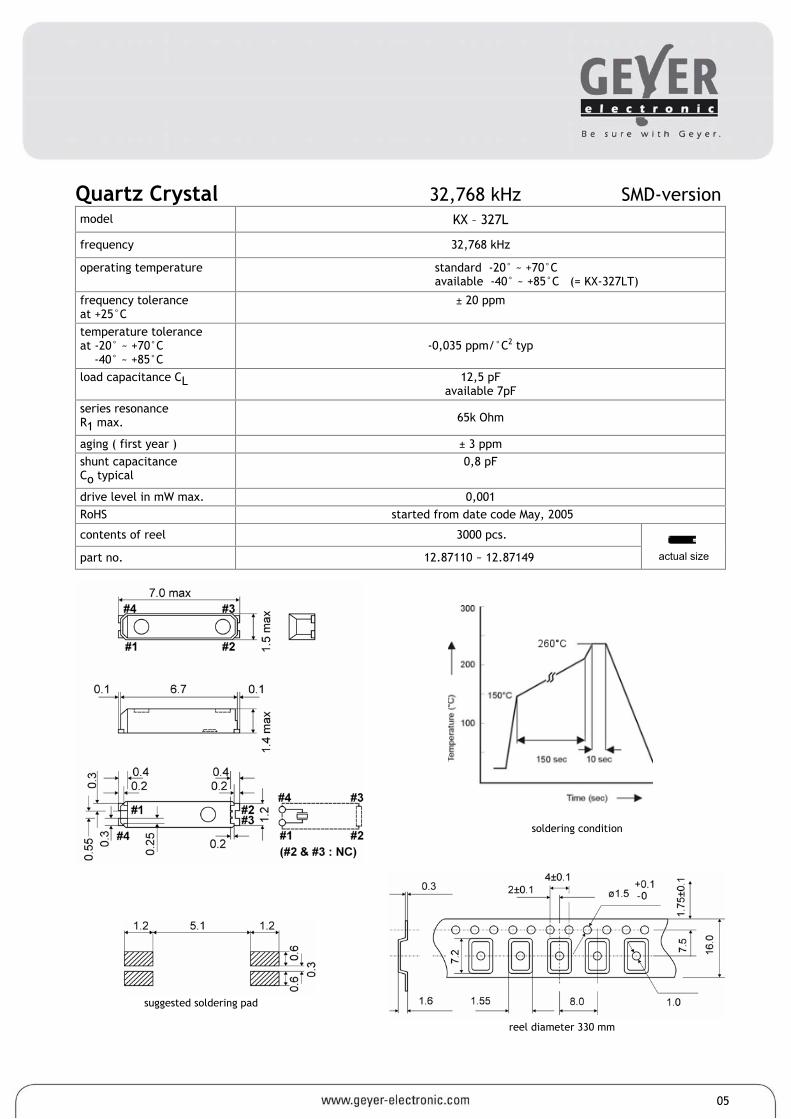
Quartz Crystal 32,768 kHz SMD-version model KX – 327L
frequency 32,768 kHz
operating temperature standard -20° ~ +70°C available -40° ~ +85°C (= KX-327LT)
frequency tolerance at +25°C
± 20 ppm
temperature tolerance at -20° ~ +70°C -40° ~ +85°C
-0,035 ppm/°C2 typ
load capacitance CL 12,5 pF available 7pF
series resonance R1 max. 65k Ohm
aging ( first year ) ± 3 ppm shunt capacitance Co typical
0,8 pF
drive level in mW max. 0,001 RoHS started from date code May, 2005
contents of reel 3000 pcs.
part no. 12.87110 ~ 12.87149
05
reel diameter 330 mm
suggested soldering pad
actual size
soldering condition

Quartz Crystal 32,768 kHz SMD-version model KX–327NHT frequency 32,768 kHz operating temperature -40° ~ +85°C frequency tolerance (df/F) at +25°C ± 3°C ± 20 ppm (±0,002%)
temperature tolerance at -40° ~ +85°C
-0,035 ppm/°C2 typ.
storage temperature range -55°C ~ +125°C turnover temperature +25°C ±5°C capacitance ratio (C0/C1) 440, typ. load capacitance CL 12,5 pF ± 1,0 pF
motional capacitance (C1) 0,0036 pF, typ. series resonance R1 max. 80k Ohm
aging (df/F) ( first year ) at 25°C ±3°C ± 3 ppm max.
shunt capacitance Co 1,6 pF typ.
drive level in µW max. 0,1 typ. (1,0 µW max.) quality factor (Q) 20000 min. reflow soldering condition 10 seconds at +260°C max. (2 times max.) RoHS since production start contents of reel 3000 pcs. part no. 12.87110 ~ 12.87149
reel diameter 180 mm
soldering condition
suggested soldering pad
actual size
06
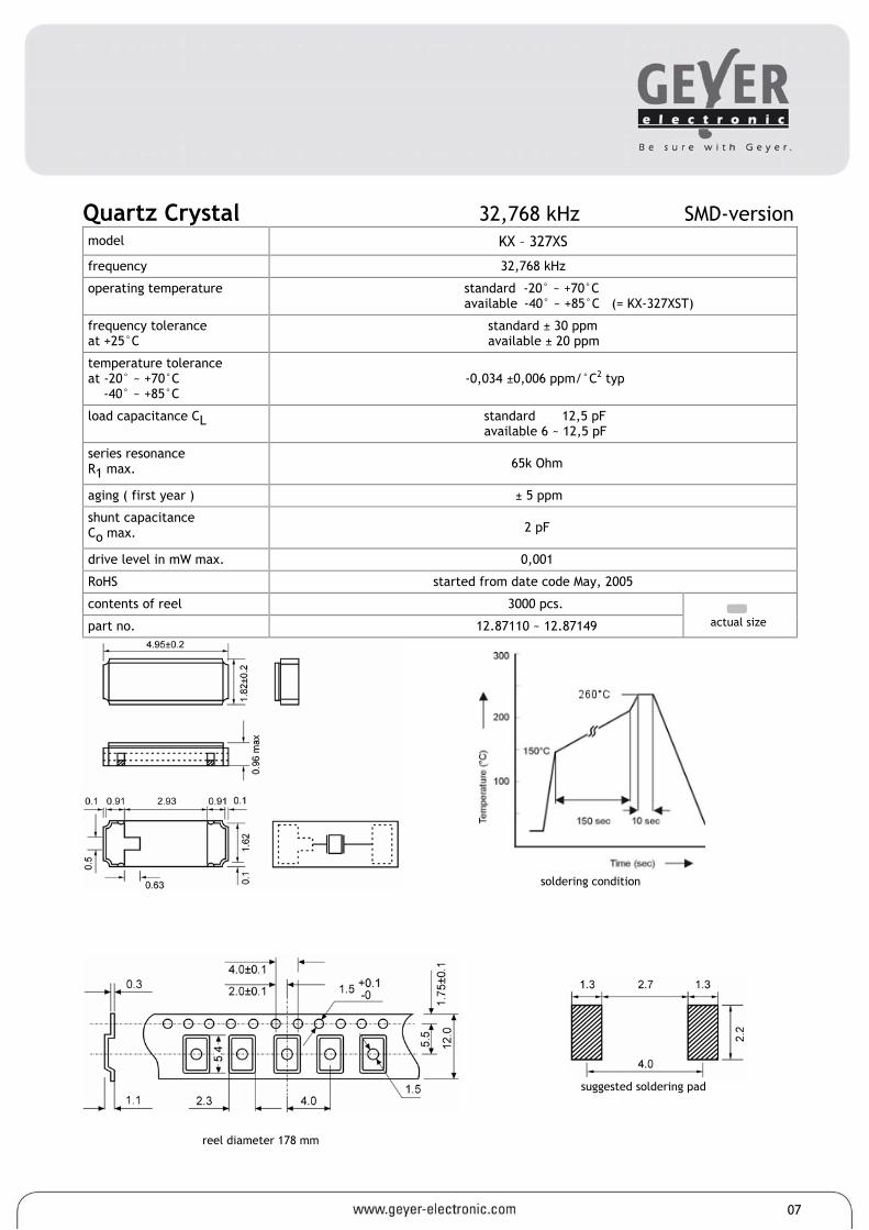
Quartz Crystal 32,768 kHz SMD-version model KX – 327XS
frequency 32,768 kHz
operating temperature standard -20° ~ +70°C available -40° ~ +85°C (= KX-327XST)
frequency tolerance at +25°C
standard ± 30 ppm available ± 20 ppm
temperature tolerance at -20° ~ +70°C -40° ~ +85°C
-0,034 ±0,006 ppm/°C2 typ
load capacitance CL standard 12,5 pF available 6 ~ 12,5 pF
series resonance R1 max. 65k Ohm
aging ( first year ) ± 5 ppm
shunt capacitance Co max. 2 pF
drive level in mW max. 0,001
RoHS started from date code May, 2005
contents of reel 3000 pcs.
part no. 12.87110 ~ 12.87149
reel diameter 178 mm
actual size
soldering condition
suggested soldering pad
07
actual size
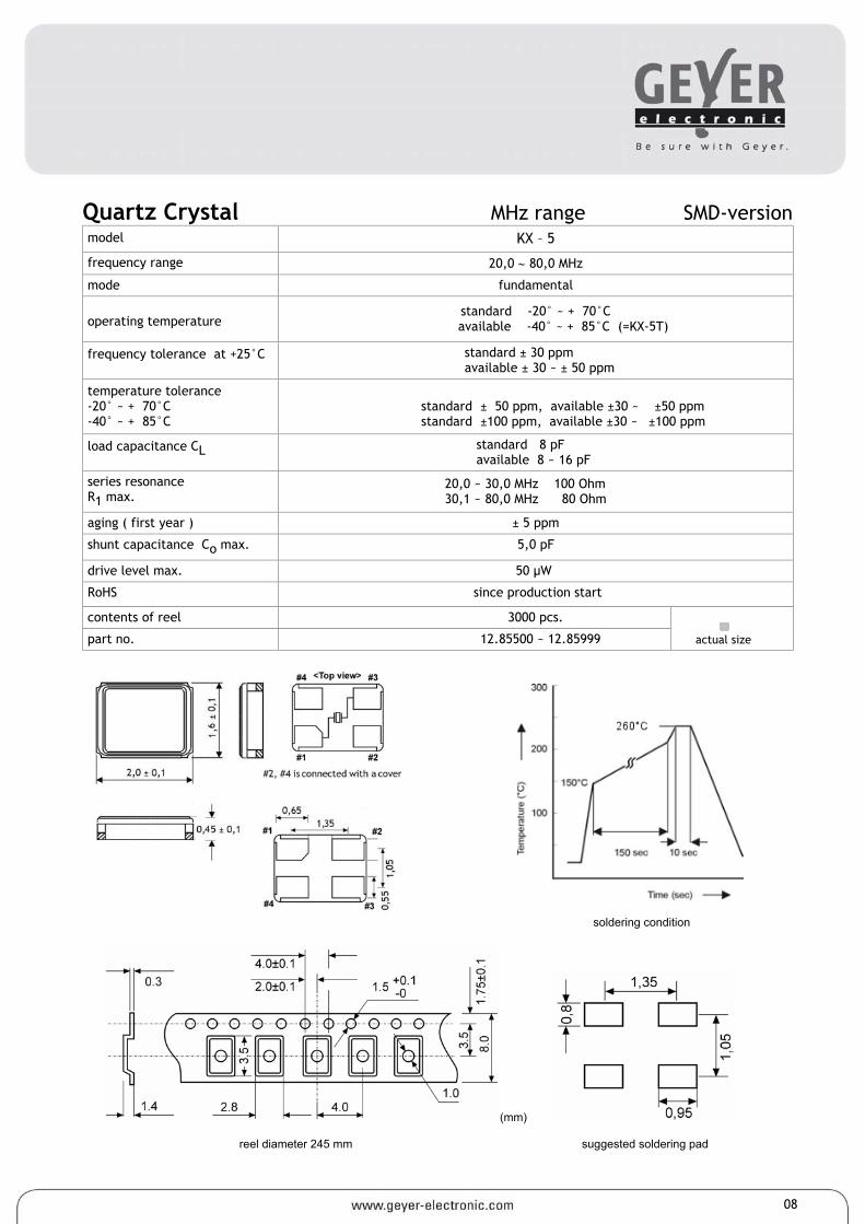
Quartz Crystal MHz range SMD-version model KX – 5
frequency range 20,0 ∼ 80,0 MHz
mode fundamental
operating temperature standard -20° ~ + 70°C
available -40° ~ + 85°C (=KX-5T)
frequency tolerance at +25°C standard ± 30 ppm available ± 30 ~ ± 50 ppm
temperature tolerance -20° ~ + 70°C -40° ~ + 85°C
standard ± 50 ppm, available ±30 ~ ±50 ppm standard ±100 ppm, available ±30 ~ ±100 ppm
load capacitance CL standard 8 pF available 8 ~ 16 pF
series resonance R1 max.
20,0 ~ 30,0 MHz 100 Ohm 30,1 ~ 80,0 MHz 80 Ohm
aging ( first year ) ± 5 ppm
shunt capacitance Co max. 5,0 pF
drive level max. 50 µW
RoHS since production start
contents of reel 3000 pcs.
part no. 12.85500 ~ 12.85999
soldering condition
(mm) reel diameter 245 mm suggested soldering pad
08
actual size
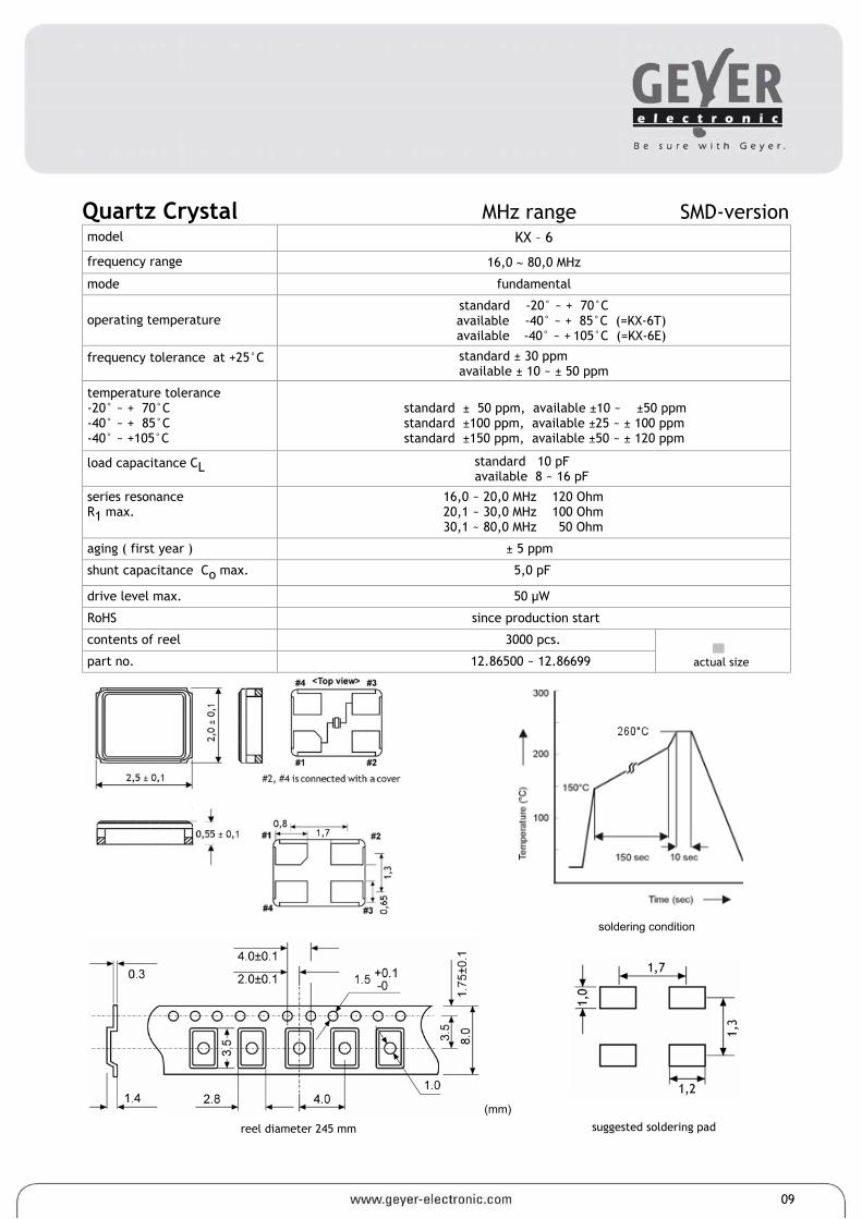
Quartz Crystal MHz range SMD-version model KX – 6
frequency range 16,0 ∼ 80,0 MHz
mode fundamental
operating temperature standard -20° ~ + 70°C
available -40° ~ + 85°C (=KX-6T) available -40° ~ + 105°C (=KX-6E)
frequency tolerance at +25°C standard ± 30 ppm available ± 10 ~ ± 50 ppm
temperature tolerance -20° ~ + 70°C -40° ~ + 85°C -40° ~ +105°C
standard ± 50 ppm, available ±10 ~ ±50 ppm standard ±100 ppm, available ±25 ~ ± 100 ppm standard ±150 ppm, available ±50 ~ ± 120 ppm
load capacitance CL standard 10 pF available 8 ~ 16 pF
series resonance R1 max.
16,0 ~ 20,0 MHz 120 Ohm 20,1 ~ 30,0 MHz 100 Ohm 30,1 ~ 80,0 MHz 50 Ohm
aging ( first year ) ± 5 ppm
shunt capacitance Co max. 5,0 pF
drive level max. 50 µW
RoHS since production start
contents of reel 3000 pcs.
part no. 12.86500 ~ 12.86699
soldering condition
(mm)
reel diameter 245 mm
suggested soldering pad
09
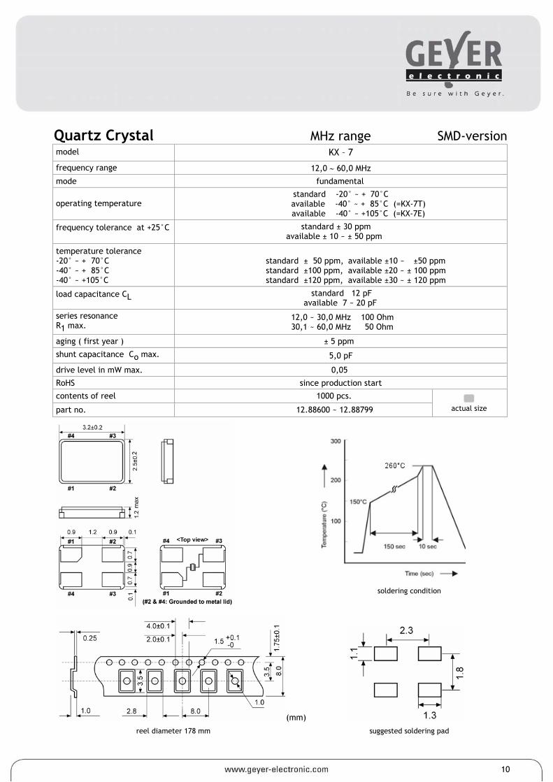
10
actual size
Quartz Crystal MHz range SMD-version model KX – 7
frequency range 12,0 ∼ 60,0 MHz
mode fundamental
operating temperature standard -20° ~ + 70°C
available -40° ~ + 85°C (=KX-7T) available -40° ~ +105°C (=KX-7E)
frequency tolerance at +25°C standard ± 30 ppm available ± 10 ~ ± 50 ppm
temperature tolerance -20° ~ + 70°C -40° ~ + 85°C -40° ~ +105°C
standard ± 50 ppm, available ±10 ~ ±50 ppm standard ±100 ppm, available ±20 ~ ± 100 ppm standard ±120 ppm, available ±30 ~ ± 120 ppm
load capacitance CL standard 12 pF available 7 ~ 20 pF
series resonance R1 max.
12,0 ~ 30,0 MHz 100 Ohm 30,1 ~ 60,0 MHz 50 Ohm
aging ( first year ) ± 5 ppm
shunt capacitance Co max. 5,0 pF
drive level in mW max. 0,05
RoHS since production start
contents of reel 1000 pcs.
part no. 12.88600 ~ 12.88799
soldering condition
(mm)
reel diameter 178 mm suggested soldering pad
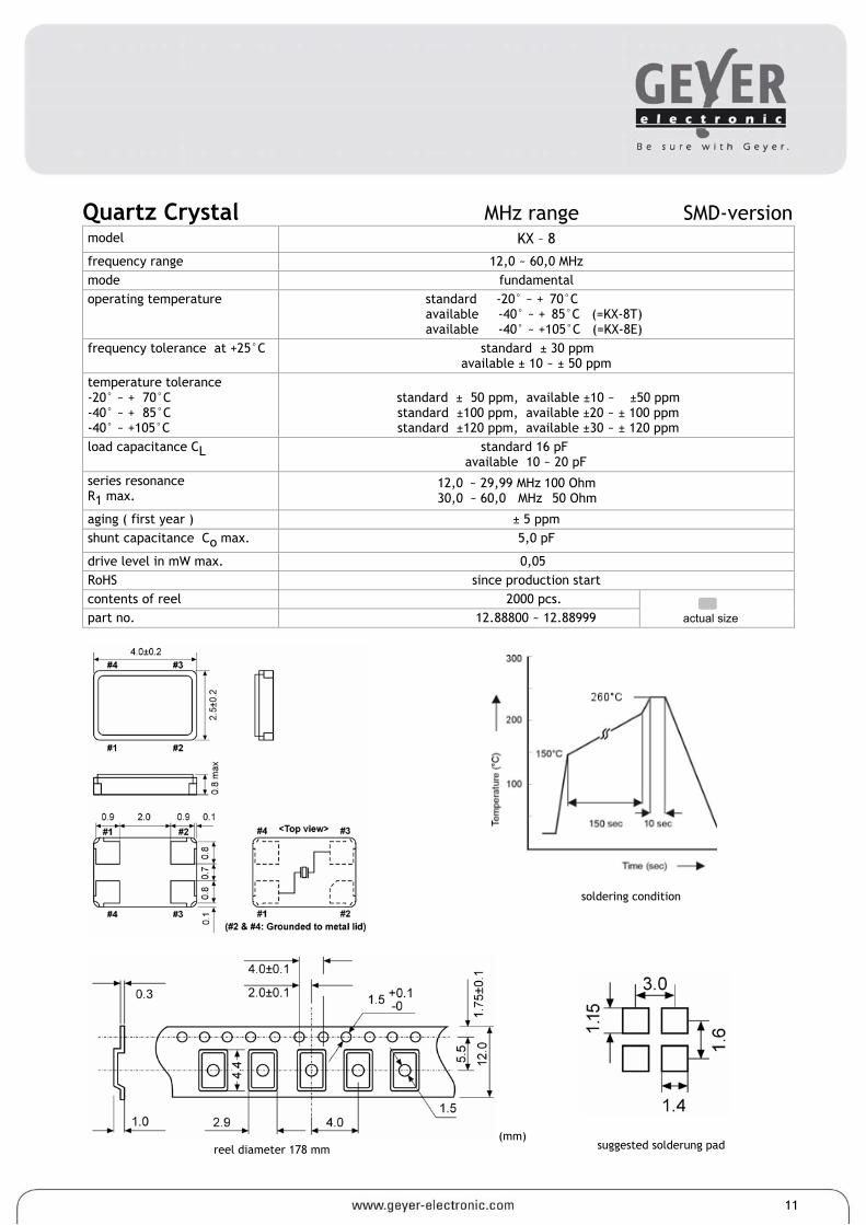
actual size
Quartz Crystal MHz range SMD-version model KX – 8
frequency range 12,0 ~ 60,0 MHz mode fundamental operating temperature standard -20° ~ + 70°C
available -40° ~ + 85°C (=KX-8T) available -40° ~ +105°C (=KX-8E)
frequency tolerance at +25°C standard ± 30 ppm available ± 10 ~ ± 50 ppm
temperature tolerance -20° ~ + 70°C -40° ~ + 85°C -40° ~ +105°C
standard ± 50 ppm, available ±10 ~ ±50 ppm standard ±100 ppm, available ±20 ~ ± 100 ppm standard ±120 ppm, available ±30 ~ ± 120 ppm
load capacitance CL standard 16 pF available 10 ~ 20 pF
series resonance R1 max.
12,0 ~ 29,99 MHz 100 Ohm 30,0 ~ 60,0 MHz 50 Ohm
aging ( first year ) ± 5 ppm shunt capacitance Co max. 5,0 pF
drive level in mW max. 0,05 RoHS since production start contents of reel 2000 pcs. part no. 12.88800 ~ 12.88999
soldering condition
(mm) reel diameter 178 mm
suggested solderung pad
11
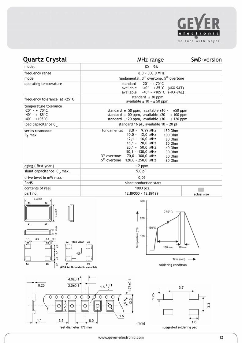
12
actual size
Quartz Crystal MHz range SMD-version model KX – 9A
frequency range 8,0 ~ 300,0 MHz mode fundamental, 3rd overtone, 5th overtone operating temperature standard -20° ~ + 70°C
available -40° ~ + 85°C (=KX-9AT) available -40° ~ +105°C (=KX-9AE)
frequency tolerance at +25°C standard ± 30 ppm available ± 10 ~ ± 50 ppm
temperature tolerance -20° ~ + 70°C -40° ~ + 85°C -40° ~ +105°C
standard ± 50 ppm, available ±10 ~ ±50 ppm standard ±100 ppm, available ±20 ~ ± 100 ppm standard ±120 ppm, available ±30 ~ ± 120 ppm
load capacitance CL standard 16 pF, available 10 ~ 20 pF
series resonance R1 max.
fundamental 8,0 ~ 9,99 MHz 10,0 ~ 12,0 MHz
12,1 ~ 16,0 MHz 16,1 ~ 20,0 MHz 20,1 ~ 50,0 MHz 50,1 ~ 130,0 MHz 3rd overtone 70,0 ~ 300,0 MHz 5th overtone 120,0 ~ 250,0 MHz
150 Ohm 100 Ohm 80 Ohm 60 Ohm 40 Ohm 30 Ohm 80 Ohm 80 Ohm
aging ( first year ) ± 2 ppm shunt capacitance Co max. 5,0 pF
drive level in mW max. 0,05 RoHS since production start contents of reel 1000 pcs. part no. 12.89000 ~ 12.89199
soldering condition
(mm) reel diameter 178 mm suggested soldering pad
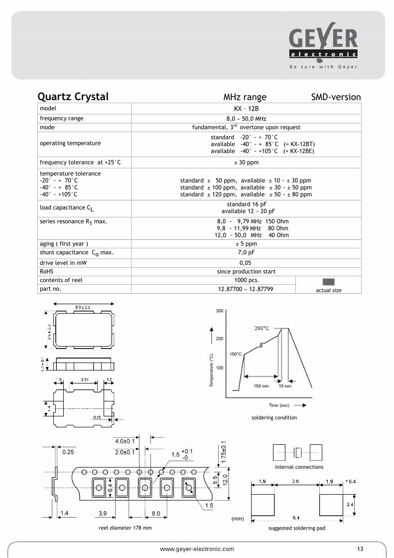
actual size
Quartz Crystal MHz range SMD-version model KX – 12B frequency range 8,0 ∼ 50,0 MHz mode fundamental, 3rd overtone upon request
operating temperature standard -20° ~ + 70°C available -40° ~ + 85°C (= KX-12BT) available -40° ~ +105°C (= KX-12BE)
frequency tolerance at +25°C ± 30 ppm
temperature tolerance -20° ~ + 70°C -40° ~ + 85°C -40° ~ +105°C
standard ± 50 ppm, available ± 10 ~ ± 30 ppm standard ± 100 ppm, available ± 30 ~ ± 50 ppm standard ± 120 ppm, available ± 50 ~ ± 80 ppm
load capacitance CL standard 16 pF available 12 ~ 20 pF
series resonance R1 max. 8,0 ~ 9,79 MHz 150 Ohm 9,8 ~ 11,99 MHz 80 Ohm 12,0 ~ 50,0 MHz 40 Ohm
aging ( first year ) ± 5 ppm shunt capacitance Co max. 7,0 pF
drive level in mW 0,05 RoHS since production start contents of reel 1000 pcs. part no. 12.87700 ∼ 12.87799
soldering condition
(mm)
reel diameter 178 mm
internal connections
suggested soldering pad
13
14
actual size
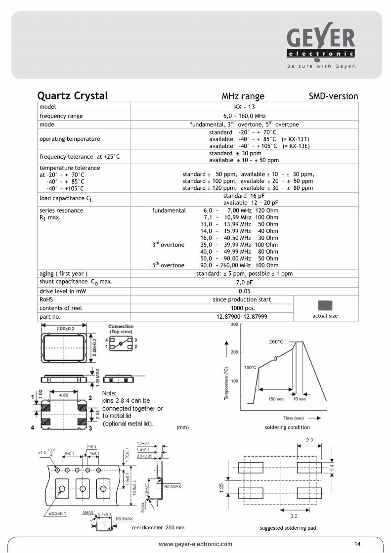
Quartz Crystal MHz range SMD-version model KX - 13 frequency range 6,0 ~ 160,0 MHz mode fundamental, 3rd overtone, 5th overtone
operating temperature standard -20° ~ + 70°C available -40° ~ + 85°C (= KX-13T) available -40° ~ + 105°C (= KX-13E)
frequency tolerance at +25°C standard ± 30 ppm available ± 10 ~ ± 50 ppm
temperature tolerance at -20° ~ + 70°C -40° ~ + 85°C -40° ~ +105°C
standard ± 50 ppm, available ± 10 ~ ± 30 ppm, standard ± 100 ppm, available ± 20 ~ ± 50 ppm standard ± 120 ppm, available ± 30 ~ ± 80 ppm
load capacitance CL standard 16 pF available 12 ~ 20 pF
series resonance R1 max.
fundamental 6,0 ~ 7,00 MHz 120 Ohm 7,1 ~ 10,99 MHz 100 Ohm 11,0 ~ 13,99 MHz 50 Ohm 14,0 ~ 15,99 MHz 40 Ohm 16,0 ~ 40,50 MHz 30 Ohm 3rd overtone 35,0 ~ 39,99 MHz 100 Ohm 40,0 ~ 49,99 MHz 80 Ohm 50,0 ~ 90,00 MHz 50 Ohm 5th overtone 90,0 ~ 260,00 MHz 100 Ohm
aging ( first year ) standard: ± 5 ppm, possible ± 1 ppm shunt capacitance Co max. 7,0 pF drive level in mW 0,05 RoHS since production start contents of reel 1000 pcs. part no. 12.87900~12.87999
(mm) soldering condition
suggested soldering pad
reel diameter 250 mm
actual size
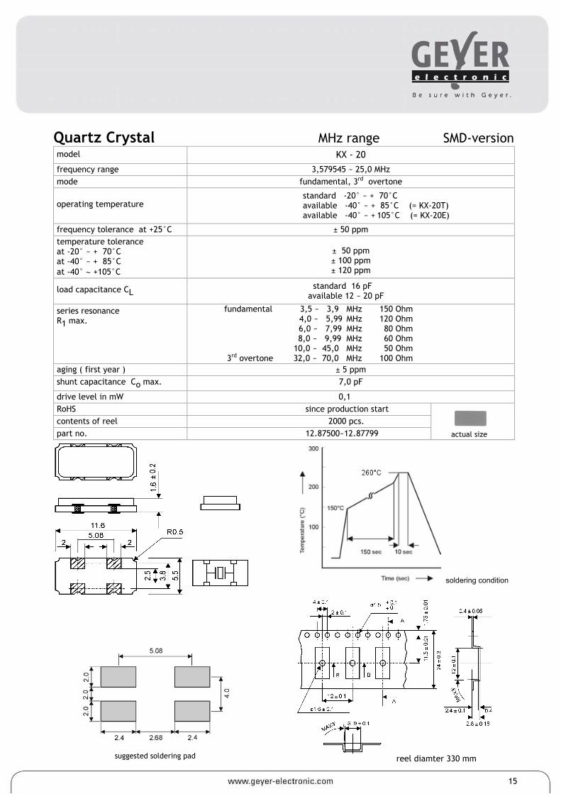
Quartz Crystal MHz range SMD-version model KX - 20
frequency range 3,579545 ~ 25,0 MHz mode fundamental, 3rd overtone
operating temperature standard -20° ~ + 70°C available -40° ~ + 85°C (= KX-20T) available -40° ~ + 105°C (= KX-20E)
frequency tolerance at +25°C ± 50 ppm temperature tolerance at -20° ~ + 70°C at -40° ~ + 85°C at -40° ∼ +105°C
± 50 ppm ± 100 ppm ± 120 ppm
load capacitance CL standard 16 pF available 12 ~ 20 pF
series resonance R1 max.
fundamental 3,5 ~ 3,9 MHz 4,0 ~ 5,99 MHz 6,0 ~ 7,99 MHz 8,0 ~ 9,99 MHz 10,0 ~ 45,0 MHz 3rd overtone 32,0 ~ 70,0 MHz
150 Ohm 120 Ohm 80 Ohm 60 Ohm 50 Ohm
100 Ohm
aging ( first year ) ± 5 ppm shunt capacitance Co max. 7,0 pF
drive level in mW 0,1 RoHS since production start contents of reel 2000 pcs. part no. 12.87500~12.87799
soldering condition
suggested soldering pad
reel diamter 330 mm
15
actual size
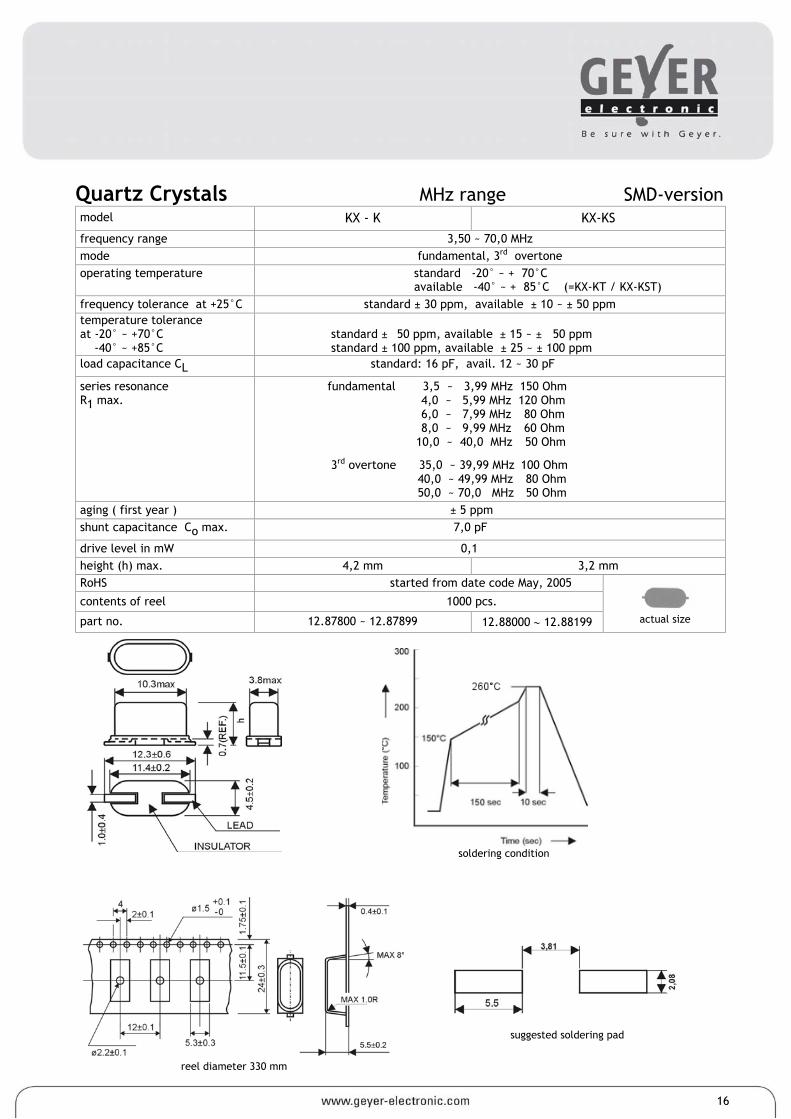
Quartz Crystals MHz range SMD-version model KX - K KX-KS
frequency range 3,50 ~ 70,0 MHz mode fundamental, 3rd overtone operating temperature standard -20° ~ + 70°C
available -40° ~ + 85°C (=KX-KT / KX-KST) frequency tolerance at +25°C standard ± 30 ppm, available ± 10 ~ ± 50 ppm temperature tolerance at -20° ~ +70°C -40° ~ +85°C
standard ± 50 ppm, available ± 15 ~ ± 50 ppm standard ± 100 ppm, available ± 25 ~ ± 100 ppm
load capacitance CL standard: 16 pF, avail. 12 ~ 30 pF
series resonance R1 max.
fundamental 3,5 ~ 3,99 MHz 150 Ohm 4,0 ~ 5,99 MHz 120 Ohm 6,0 ~ 7,99 MHz 80 Ohm 8,0 ~ 9,99 MHz 60 Ohm 10,0 ~ 40,0 MHz 50 Ohm
3rd overtone 35,0 ~ 39,99 MHz 100 Ohm 40,0 ~ 49,99 MHz 80 Ohm 50,0 ~ 70,0 MHz 50 Ohm
aging ( first year ) ± 5 ppm shunt capacitance Co max. 7,0 pF
drive level in mW 0,1 height (h) max. 4,2 mm 3,2 mm RoHS started from date code May, 2005
contents of reel 1000 pcs.
part no. 12.87800 ~ 12.87899 12.88000 ∼ 12.88199
soldering condition
reel diameter 330 mm
suggested soldering pad
16
actual size
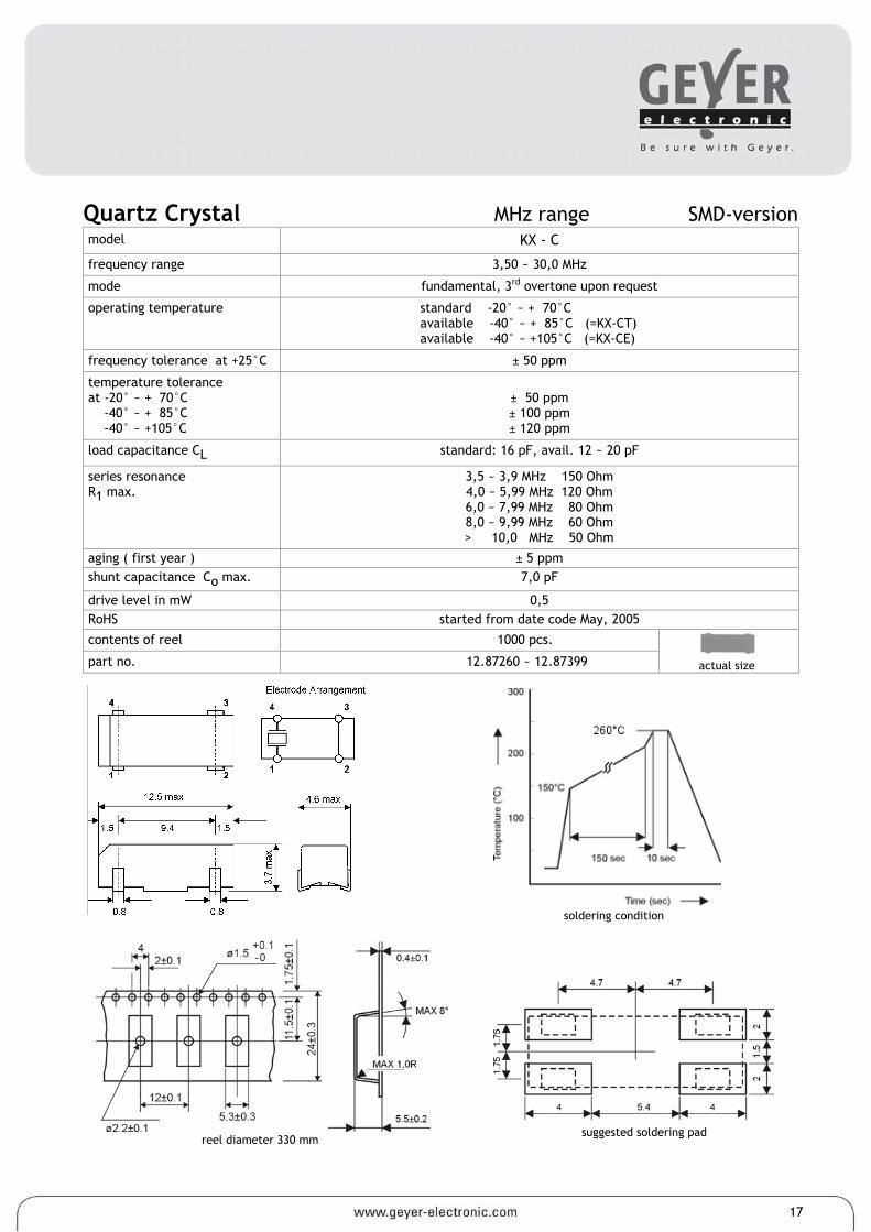
Quartz Crystal MHz range SMD-version model KX - C
frequency range 3,50 ~ 30,0 MHz
mode fundamental, 3rd overtone upon request
operating temperature standard -20° ~ + 70°C available -40° ~ + 85°C (=KX-CT) available -40° ~ +105°C (=KX-CE)
frequency tolerance at +25°C ± 50 ppm
temperature tolerance at -20° ~ + 70°C -40° ~ + 85°C -40° ~ +105°C
± 50 ppm ± 100 ppm ± 120 ppm
load capacitance CL standard: 16 pF, avail. 12 ~ 20 pF
series resonance R1 max.
3,5 ~ 3,9 MHz 150 Ohm 4,0 ~ 5,99 MHz 120 Ohm 6,0 ~ 7,99 MHz 80 Ohm 8,0 ~ 9,99 MHz 60 Ohm > 10,0 MHz 50 Ohm
aging ( first year ) ± 5 ppm shunt capacitance Co max. 7,0 pF
drive level in mW 0,5 RoHS started from date code May, 2005
contents of reel 1000 pcs.
part no. 12.87260 ~ 12.87399
17
suggested soldering pad
reel diameter 330 mm
soldering condition
actual size
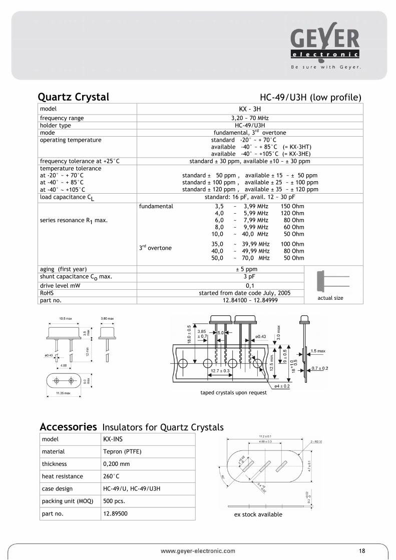
Quartz Crystal HC-49/U3H (low profile) model KX - 3H frequency range 3,20 ~ 70 MHz holder type HC-49/U3H mode fundamental, 3rd overtone operating temperature standard -20° ~ + 70°C
available -40° ~ + 85°C (= KX-3HT) available -40° ~ +105°C (= KX-3HE)
frequency tolerance at +25°C standard ± 30 ppm, available ±10 ~ ± 30 ppm temperature tolerance at -20° ~ + 70°C at -40° ~ + 85°C at -40° ∼ +105°C
standard ± 50 ppm , available ± 15 ~ ± 50 ppm standard ± 100 ppm , available ± 25 ~ ± 100 ppm standard ± 120 ppm , available ± 35 ~ ± 120 ppm
load capacitance CL standard: 16 pF, avail. 12 ~ 30 pF
series resonance R1 max.
fundamental 3rd overtone
3,5 4,0 6,0 8,0 10,0
35,0 40,0 50,0
~ 3,99 MHz ~ 5,99 MHz ~ 7,99 MHz ~ 9,99 MHz ~ 40,0 MHz
~ 39,99 MHz ~ 49,99 MHz ~ 70,0 MHz
150 Ohm120 Ohm80 Ohm60 Ohm50 Ohm
100 Ohm80 Ohm50 Ohm
aging (first year) ± 5 ppm shunt capacitance Co max. 3 pF
drive level mW 0,1 RoHS started from date code July, 2005 part no. 12.84100 ~ 12.84999
18
taped crystals upon request
Accessories Insulators for Quartz Crystals model KX-INS
material Tepron (PTFE)
thickness 0,200 mm
heat resistance 260°C
case design HC-49/U, HC-49/U3H
packing unit (MOQ) 500 pcs.
part no. 12.89500 ex stock available
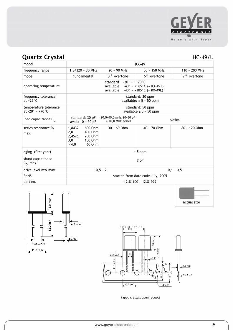
Quartz Crystal HC-49/U model KX-49
frequency range 1,84320 ~ 30 MHz 20 ~ 90 MHz 50 ~ 150 MHz 110 ~ 200 MHz
mode fundamental 3rd overtone 5th overtone 7th overtone
operating temperature standard -20° ~ + 70°C available -40° ~ + 85°C (= KX-49T) available -40° ~ +105°C (= KX-49E)
frequency tolerance at +25°C
standard: 30 ppm available: ± 5 ~ 50 ppm
temperature tolerance at -20° ~ +70°C
standard: 50 ppm available ± 5 ~ 50 ppm
load capacitance CL standard: 30 pF avail: 10 ~ 30 pF
20,0~40,0 MHz: 20~30 pF > 40,0 MHz: series series
series resonance R1 max.
1,8432 2,0 2,4576 3,0 > 4,0
600 Ohm 400 Ohm 200 Ohm 150 Ohm 60 Ohm
30 ~ 60 Ohm 40 ~ 70 Ohm 80 ~ 120 Ohm
aging (first year) ± 5 ppm
shunt capacitance Co max.
7 pF
drive level mW max 0,5 ~ 2 0,1 ~ 0,5
RoHS started from date code July, 2005
part no. 12.81100 ~ 12.81999
actual size
19
taped crystals upon request
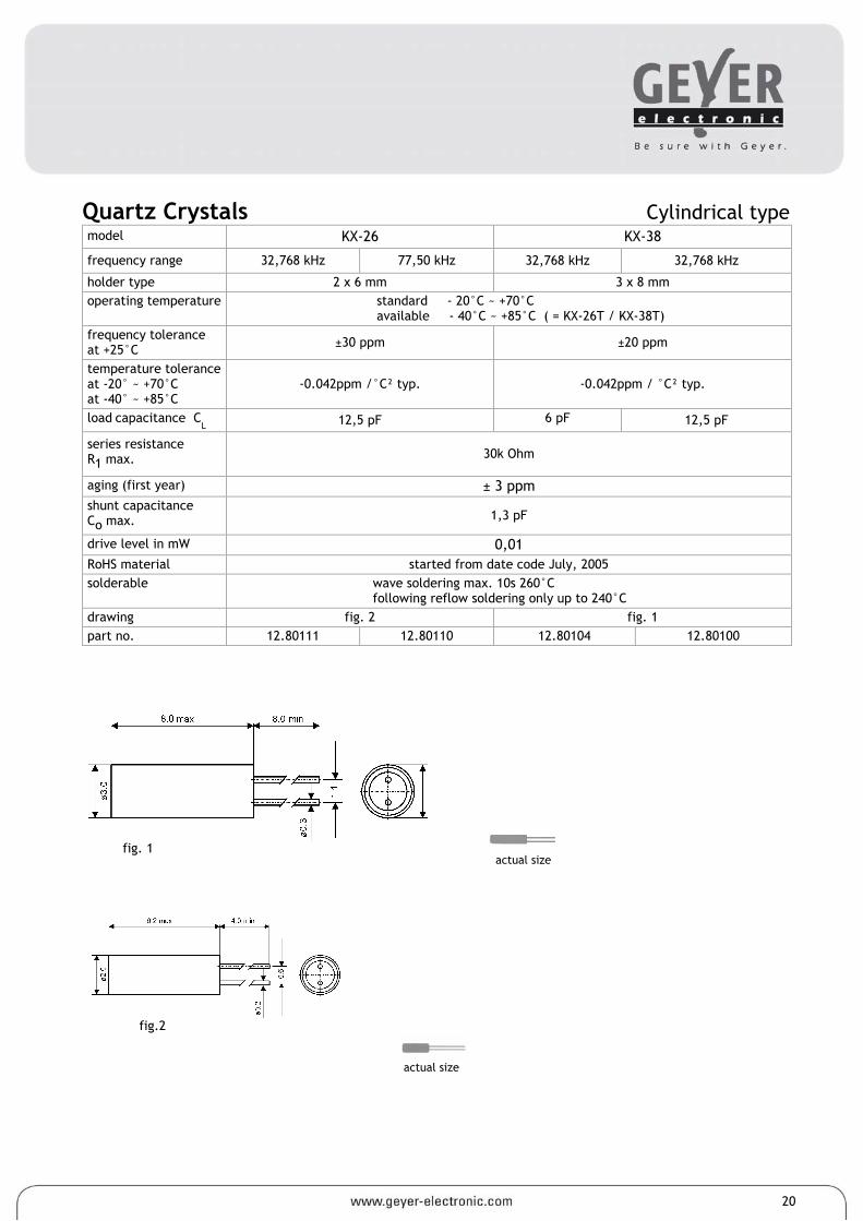
Quartz Crystals Cylindrical type model KX-26 KX-38
frequency range 32,768 kHz 77,50 kHz 32,768 kHz 32,768 kHz
holder type 2 x 6 mm 3 x 8 mm operating temperature standard - 20°C ~ +70°C
available - 40°C ~ +85°C ( = KX-26T / KX-38T) frequency tolerance at +25°C ±30 ppm ±20 ppm
temperature tolerance at -20° ~ +70°C at -40° ~ +85°C
-0.042ppm /°C² typ. -0.042ppm / °C² typ.
load capacitance CL 12,5 pF 6 pF 12,5 pF
series resistance R1 max. 30k Ohm
aging (first year) ± 3 ppm shunt capacitance Co max. 1,3 pF
drive level in mW 0,01 RoHS material started from date code July, 2005 solderable wave soldering max. 10s 260°C
following reflow soldering only up to 240°C drawing fig. 2 fig. 1 part no. 12.80111 12.80110 12.80104 12.80100
fig. 1
fig.2
20
actual size
actual size
actual size
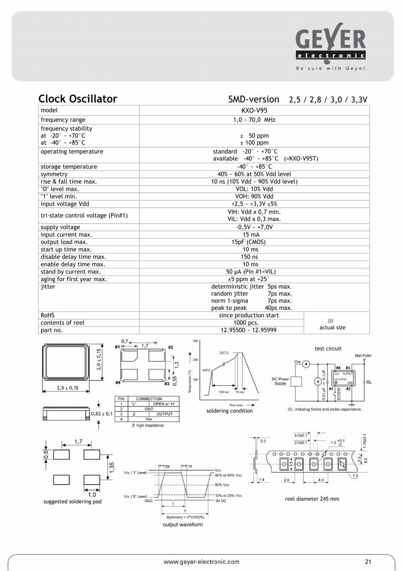
Clock Oscillator SMD-version 2,5 / 2,8 / 3,0 / 3,3V model KXO-V95 frequency range 1,0 ~ 70,0 MHz frequency stability at -20° ~ +70°C at -40° ~ +85°C
± 50 ppm ± 100 ppm
operating temperature standard -20° ~ +70°C available -40° ~ +85°C (=KXO-V95T)
storage temperature -40° ~ +85°C symmetry 40% ~ 60% at 50% Vdd level rise & fall time max. 10 ns (10% Vdd ~ 90% Vdd level) "O" level max. VOL: 10% Vdd "1" level min. VOH: 90% Vdd input voltage Vdd +2,5 ~ +3,3V ±5%
tri-state control voltage (Pin#1) VIH: Vdd x 0,7 min. VIL: Vdd x 0,3 max.
supply voltage -0,5V ~ +7,0V input current max. 15 mA output load max. 15pF (CMOS) start up time max. 10 ms disable delay time max. 150 ns enable delay time max. 10 ms stand by current max. 50 µA (Pin #1=VIL) aging for first year max. ±5 ppm at +25° jitter deterministic jitter 5ps max.
random jitter 7ps max. norm 1-sigma 7ps max. peak to peak 40ps max.
RoHS since production start contents of reel 1000 pcs. part no. 12.95500 ~ 12.95999
21
output waveform
test circuit
reel diameter 245 mm
suggested soldering pad
soldering condition
actual size
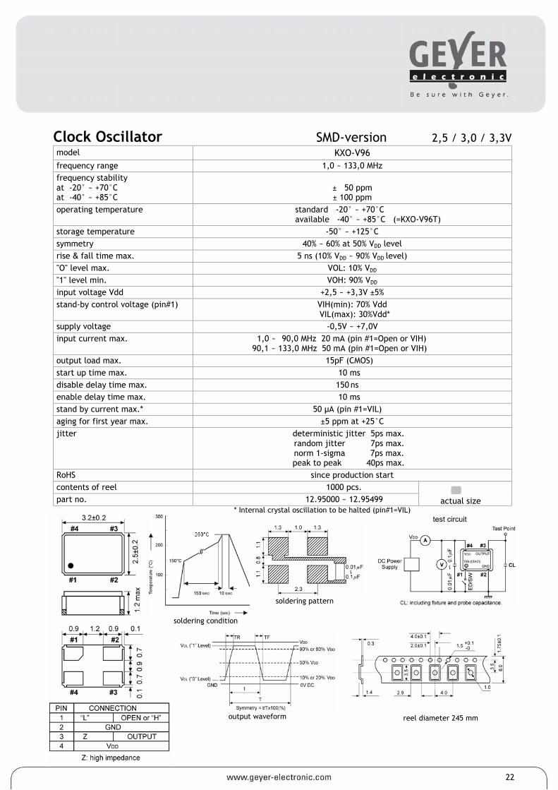
Clock Oscillator SMD-version 2,5 / 3,0 / 3,3V model KXO-V96 frequency range 1,0 ~ 133,0 MHz frequency stability at -20° ~ +70°C at -40° ~ +85°C
± 50 ppm ± 100 ppm
operating temperature standard -20° ~ +70°C available -40° ~ +85°C (=KXO-V96T)
storage temperature -50° ~ +125°C symmetry 40% ~ 60% at 50% VDD level rise & fall time max. 5 ns (10% VDD ~ 90% VDD level) "O" level max. VOL: 10% VDD "1" level min. VOH: 90% VDD input voltage Vdd +2,5 ~ +3,3V ±5% stand-by control voltage (pin#1) VIH(min): 70% Vdd
VIL(max): 30%Vdd* supply voltage -0,5V ~ +7,0V input current max. 1,0 ~ 90,0 MHz 20 mA (pin #1=Open or VIH)
90,1 ~ 133,0 MHz 50 mA (pin #1=Open or VIH) output load max. 15pF (CMOS) start up time max. 10 ms disable delay time max. 150 ns enable delay time max. 10 ms stand by current max.* 50 µA (pin #1=VIL) aging for first year max. ±5 ppm at +25°C jitter deterministic jitter 5ps max.
random jitter 7ps max. norm 1-sigma 7ps max. peak to peak 40ps max.
RoHS since production start contents of reel 1000 pcs. part no. 12.95000 ~ 12.95499
* Internal crystal oscillation to be halted (pin#1=VIL)
22
output waveform
test circuit
reel diameter 245 mm
soldering pattern
soldering condition
actual size
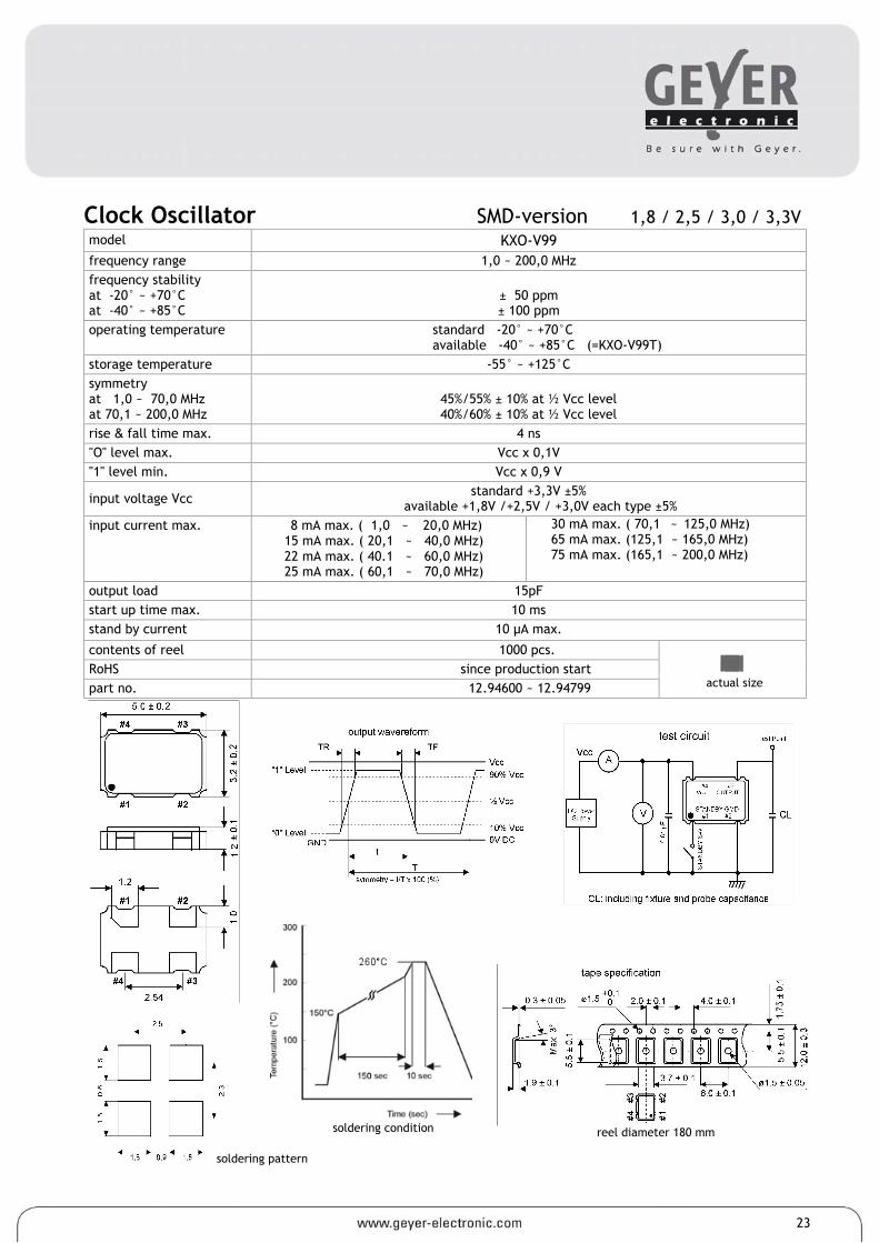
Clock Oscillator SMD-version 1,8 / 2,5 / 3,0 / 3,3V model KXO-V99 frequency range 1,0 ~ 200,0 MHz frequency stability at -20° ~ +70°C at -40° ~ +85°C
± 50 ppm ± 100 ppm
operating temperature standard -20° ~ +70°C available -40° ~ +85°C (=KXO-V99T)
storage temperature -55° ~ +125°C symmetry at 1,0 ~ 70,0 MHz at 70,1 ~ 200,0 MHz
45%/55% ± 10% at ½ Vcc level 40%/60% ± 10% at ½ Vcc level
rise & fall time max. 4 ns "O" level max. Vcc x 0,1V "1" level min. Vcc x 0,9 V
input voltage Vcc standard +3,3V ±5% available +1,8V /+2,5V / +3,0V each type ±5%
input current max. 8 mA max. ( 1,0 ~ 20,0 MHz) 15 mA max. ( 20,1 ~ 40,0 MHz) 22 mA max. ( 40.1 ~ 60,0 MHz) 25 mA max. ( 60,1 ~ 70,0 MHz)
30 mA max. ( 70,1 ~ 125,0 MHz) 65 mA max. (125,1 ~ 165,0 MHz) 75 mA max. (165,1 ~ 200,0 MHz)
output load 15pF start up time max. 10 ms stand by current 10 µA max.
contents of reel 1000 pcs. RoHS since production start part no. 12.94600 ~ 12.94799
23
reel diameter 180 mm
soldering condition
soldering pattern
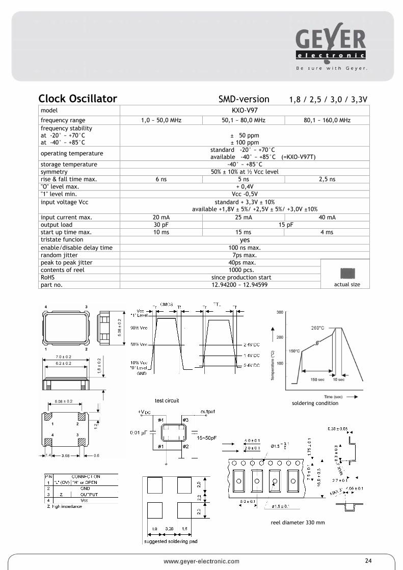
Clock Oscillator SMD-version 1,8 / 2,5 / 3,0 / 3,3V model KXO-V97 frequency range 1,0 ~ 50,0 MHz 50,1 ~ 80,0 MHz 80,1 ~ 160,0 MHz frequency stability at -20° ~ +70°C at -40° ~ +85°C
± 50 ppm ± 100 ppm
operating temperature standard -20° ~ +70°C available -40° ~ +85°C (=KXO-V97T)
storage temperature -40° ~ +85°C symmetry 50% ± 10% at ½ Vcc level rise & fall time max. 6 ns 5 ns 2,5 ns "O" level max. + 0,4V "1" level min. Vcc -0,5V input voltage Vcc standard + 3,3V ± 10%
available +1,8V ± 5%/ +2,5V ± 5%/ +3,0V ±10% input current max. 20 mA 25 mA 40 mA output load 30 pF 15 pF start up time max. 10 ms 15 ms 4 ms tristate funcion yes enable/disable delay time 100 ns max. random jitter 7ps max. peak to peak jitter 40ps max. contents of reel 1000 pcs. RoHS since production start part no. 12.94200 ~ 12.94599
24
soldering condition
reel diameter 330 mm
actual size
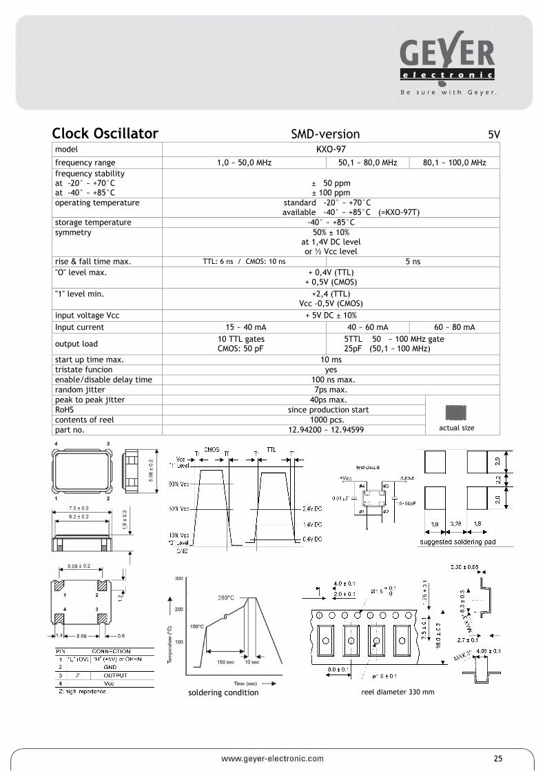
Clock Oscillator SMD-version 5V model KXO-97 frequency range 1,0 ~ 50,0 MHz 50,1 ~ 80,0 MHz 80,1 ~ 100,0 MHz frequency stability at -20° ~ +70°C at -40° ~ +85°C
± 50 ppm ± 100 ppm
operating temperature standard -20° ~ +70°C available -40° ~ +85°C (=KXO-97T)
storage temperature -40° ~ +85°C symmetry 50% ± 10%
at 1,4V DC level or ½ Vcc level
rise & fall time max. TTL: 6 ns / CMOS: 10 ns 5 ns "O" level max. + 0,4V (TTL)
+ 0,5V (CMOS) "1" level min. +2,4 (TTL)
Vcc -0,5V (CMOS) input voltage Vcc + 5V DC ± 10% Input current 15 ~ 40 mA 40 ~ 60 mA 60 ~ 80 mA
output load 10 TTL gates CMOS: 50 pF
5TTL 50 ~ 100 MHz gate 25pF (50,1 ~ 100 MHz)
start up time max. 10 ms tristate funcion yes enable/disable delay time 100 ns max. random jitter 7ps max. peak to peak jitter 40ps max. RoHS since production start contents of reel 1000 pcs. part no. 12.94200 ~ 12.94599
reel diameter 330 mm
actual size
soldering condition
25
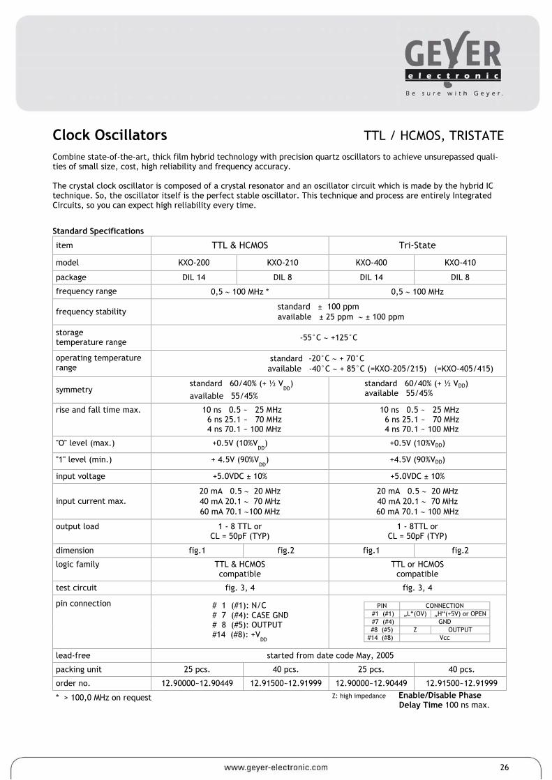
Clock Oscillators TTL / HCMOS, TRISTATE Combine state-of-the-art, thick film hybrid technology with precision quartz oscillators to achieve unsurepassed quali-ties of small size, cost, high reliability and frequency accuracy. The crystal clock oscillator is composed of a crystal resonator and an oscillator circuit which is made by the hybrid IC technique. So, the oscillator itself is the perfect stable oscillator. This technique and process are entirely Integrated Circuits, so you can expect high reliability every time.
Standard Specifications
item TTL & HCMOS Tri-State
model KXO-200 KXO-210 KXO-400 KXO-410
package DIL 14 DIL 8 DIL 14 DIL 8
frequency range 0,5 ∼ 100 MHz * 0,5 ∼ 100 MHz
frequency stability standard ± 100 ppm available ± 25 ppm ∼ ± 100 ppm
storage temperature range -55°C ∼ +125°C
operating temperature range
standard -20°C ∼ + 70°C available -40°C ∼ + 85°C (=KXO-205/215) (=KXO-405/415)
symmetry standard 60/40% (+ ½ V
DD)
available 55/45% standard 60/40% (+ ½ VDD) available 55/45%
rise and fall time max. 10 ns 0.5 ~ 25 MHz 6 ns 25.1 ~ 70 MHz 4 ns 70.1 ~ 100 MHz
10 ns 0.5 ~ 25 MHz 6 ns 25.1 ~ 70 MHz 4 ns 70.1 ~ 100 MHz
"O" level (max.) +0.5V (10%VDD
) +0.5V (10%VDD)
"1" level (min.) + 4.5V (90%VDD
) +4.5V (90%VDD)
input voltage +5.0VDC ± 10% +5.0VDC ± 10%
input current max. 20 mA 0.5 ∼ 20 MHz 40 mA 20.1 ∼ 70 MHz 60 mA 70.1 ∼100 MHz
20 mA 0.5 ∼ 20 MHz 40 mA 20.1 ∼ 70 MHz 60 mA 70.1 ∼ 100 MHz
output load 1 - 8 TTL or CL = 50pF (TYP)
1 - 8TTL or CL = 50pF (TYP)
dimension fig.1 fig.2 fig.1 fig.2
logic family TTL & HCMOS compatible
TTL or HCMOS compatible
test circuit fig. 3, 4 fig. 3, 4
PIN CONNECTION
#1 (#1) „L“(OV) „H“(+5V) or OPEN #7 (#4) GND #8 (#5) Z OUTPUT
#14 (#8) Vcc
pin connection # 1 (#1): N/C # 7 (#4): CASE GND # 8 (#5): OUTPUT #14 (#8): +V
DD
lead-free started from date code May, 2005
packing unit 25 pcs. 40 pcs. 25 pcs. 40 pcs.
order no. 12.90000~12.90449 12.91500~12.91999 12.90000~12.90449 12.91500~12.91999
* > 100,0 MHz on request Z: high impedance Enable/Disable Phase Delay Time 100 ns max.
26
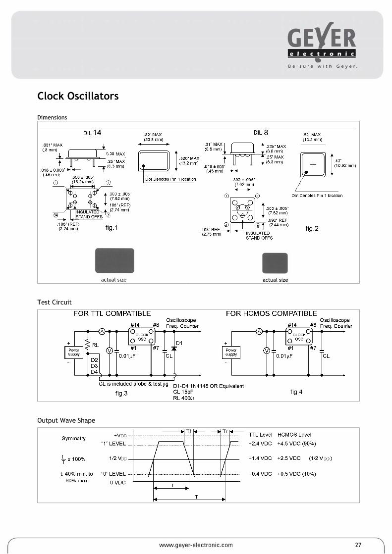
Clock Oscillators Dimensions
actual size
actual size Test Circuit
Output Wave Shape
27
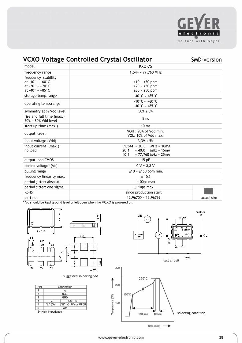
actual size
VCXO Voltage Controlled Crystal Oscillator SMD-version model KXO-75 frequency range 1,544 ~ 77,760 MHz frequency stability at -10° ~ +60°C at -20° ~ +70°C at -40° ~ +85°C
±10 ~ ±50 ppm ±20 ~ ±50 ppm ±30 ~ ±50 ppm
storage temp.range -40°C ∼ +85°C
operating temp.range -10°C ∼ +60°C -40°C ∼ +85°C
symmetry at ½ Vdd level 50% ± 5% rise and fall time (max.) 20% ~ 80% Vdd level 5 ns
start up time (max.) 10 ms
output level VOH : 90% of Vdd min. VOL: 10% of Vdd max.
input voltage (Vdd) 3,3V ± 5% input current (max.) no load
1,544 ~ 20,0 MHz = 10mA 20,1 ~ 40,0 MHz = 15mA 40,1 ~ 77,760 MHz = 25mA
output load CMOS 15 pF
control voltage* (Vc) 0 V ~ 3,3 V pulling range ±10 ~ ±150 ppm min. frequency linearity max. ± 15% period jitter: absolut ±100ps max period jitter: one sigma ± 10ps max. RoHS since production start part no. 12.96700 ~ 12.96799
* Vc should be kept ground level or left open when the VCXO is powered on.
28
test circuit
soldering condition
suggested soldering pad
PIN Connection 1 VC 2 N.C. 3 GND 4 Z OUTPUT 5 ”L” (OV) ”H”(+3,3V) or OPEN 6 Vdd Z= High Impedance
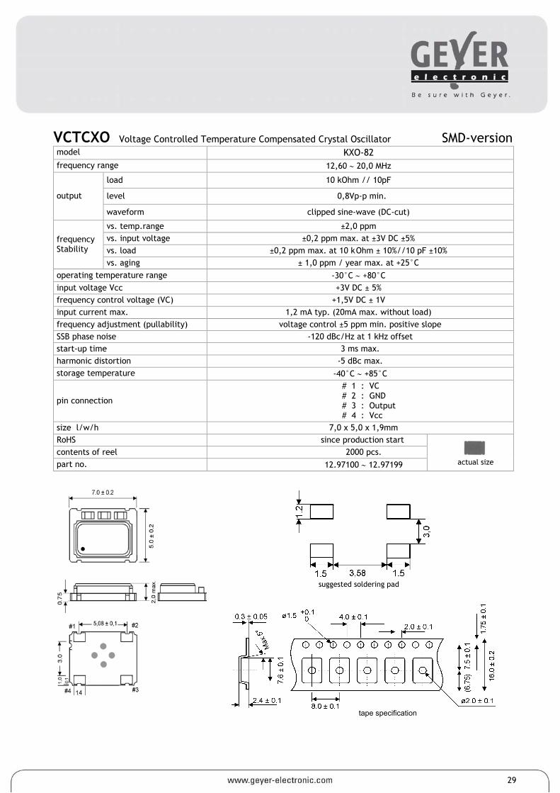
VCTCXO Voltage Controlled Temperature Compensated Crystal Oscillator SMD-version model KXO-82 frequency range 12,60 ∼ 20,0 MHz
load 10 kOhm // 10pF
level 0,8Vp-p min. output
waveform clipped sine-wave (DC-cut)
vs. temp.range ±2,0 ppm vs. input voltage ±0,2 ppm max. at ±3V DC ±5% vs. load ±0,2 ppm max. at 10 k Ohm ± 10%//10 pF ±10%
frequency Stability
vs. aging ± 1,0 ppm / year max. at +25°C operating temperature range -30°C ∼ +80°C input voltage Vcc +3V DC ± 5% frequency control voltage (VC) +1,5V DC ± 1V input current max. 1,2 mA typ. (20mA max. without load) frequency adjustment (pullability) voltage control ±5 ppm min. positive slope SSB phase noise -120 dBc/Hz at 1 kHz offset start-up time 3 ms max. harmonic distortion -5 dBc max. storage temperature -40°C ∼ +85°C
pin connection
# 1 : VC # 2 : GND # 3 : Output # 4 : Vcc
size l/w/h 7,0 x 5,0 x 1,9mm RoHS since production start contents of reel 2000 pcs. part no. 12.97100 ∼ 12.97199
29
tape specification
suggested soldering pad
actual size
reel diameter 178 mm
soldering condition
actual size
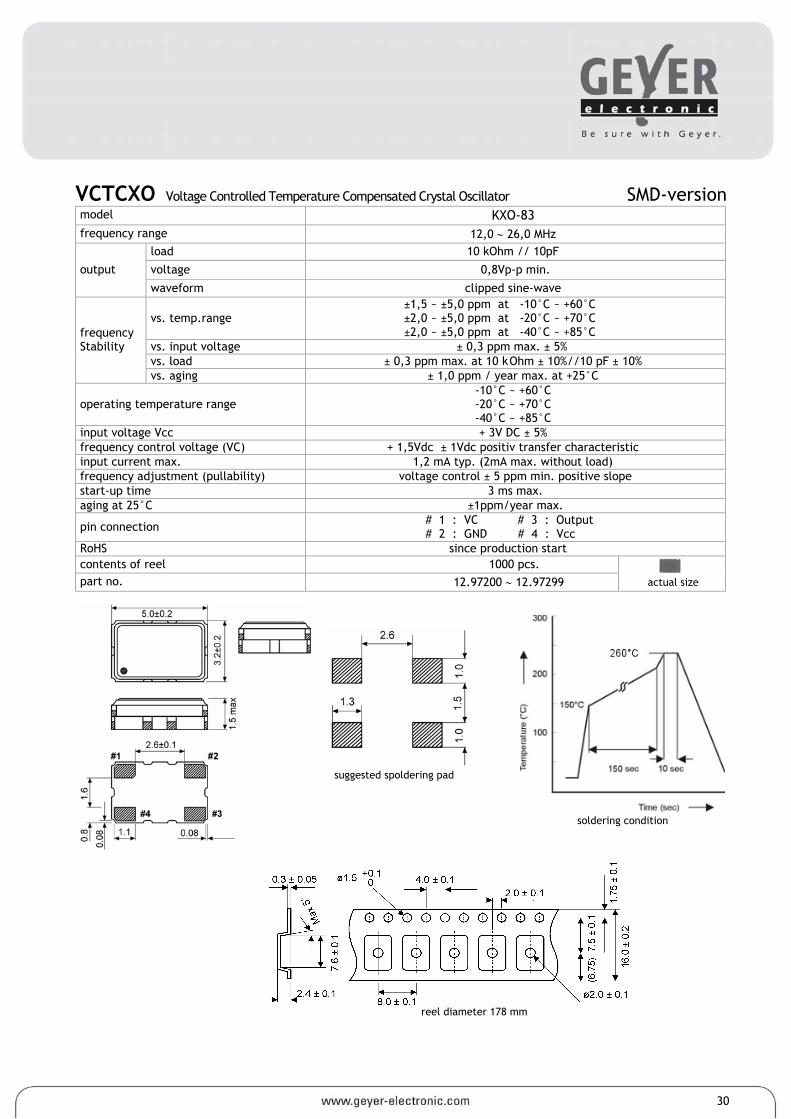
VCTCXO Voltage Controlled Temperature Compensated Crystal Oscillator SMD-version model KXO-83 frequency range 12,0 ∼ 26,0 MHz
load 10 kOhm // 10pF
voltage 0,8Vp-p min. output
waveform clipped sine-wave
vs. temp.range ±1,5 ~ ±5,0 ppm at -10°C ~ +60°C ±2,0 ~ ±5,0 ppm at -20°C ~ +70°C ±2,0 ~ ±5,0 ppm at -40°C ~ +85°C
vs. input voltage ± 0,3 ppm max. ± 5% vs. load ± 0,3 ppm max. at 10 k Ohm ± 10%//10 pF ± 10%
frequency Stability
vs. aging ± 1,0 ppm / year max. at +25°C
operating temperature range -10°C ~ +60°C -20°C ~ +70°C -40°C ~ +85°C
input voltage Vcc + 3V DC ± 5% frequency control voltage (VC) + 1,5Vdc ± 1Vdc positiv transfer characteristic input current max. 1,2 mA typ. (2mA max. without load) frequency adjustment (pullability) voltage control ± 5 ppm min. positive slope start-up time 3 ms max. aging at 25°C ±1ppm/year max.
pin connection # 1 : VC # 3 : Output # 2 : GND # 4 : Vcc
RoHS since production start contents of reel 1000 pcs. part no. 12.97200 ∼ 12.97299
30
suggested spoldering pad
actual size
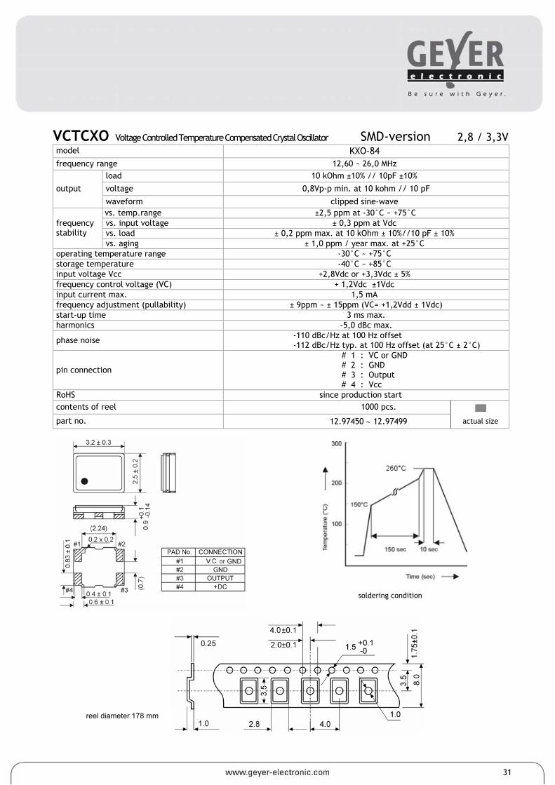
VCTCXO Voltage Controlled Temperature Compensated Crystal Oscillator SMD-version 2,8 / 3,3V model KXO-84 frequency range 12,60 ~ 26,0 MHz
load 10 kOhm ±10% // 10pF ±10%
voltage 0,8Vp-p min. at 10 kohm // 10 pF output
waveform clipped sine-wave vs. temp.range ±2,5 ppm at -30°C ~ +75°C vs. input voltage ± 0,3 ppm at Vdc vs. load ± 0,2 ppm max. at 10 kOhm ± 10%//10 pF ± 10%
frequency stability
vs. aging ± 1,0 ppm / year max. at +25°C operating temperature range -30°C ~ +75°C storage temperature -40°C ~ +85°C input voltage Vcc +2,8Vdc or +3,3Vdc ± 5% frequency control voltage (VC) + 1,2Vdc ±1Vdc input current max. 1,5 mA frequency adjustment (pullability) ± 9ppm ~ ± 15ppm (VC= +1,2Vdd ± 1Vdc) start-up time 3 ms max. harmonics -5,0 dBc max.
phase noise -110 dBc/Hz at 100 Hz offset -112 dBc/Hz typ. at 100 Hz offset (at 25°C ± 2°C)
pin connection
# 1 : VC or GND # 2 : GND # 3 : Output # 4 : Vcc
RoHS since production start contents of reel 1000 pcs.
part no. 12.97450 ∼ 12.97499
31
soldering condition
reel diameter 178 mm
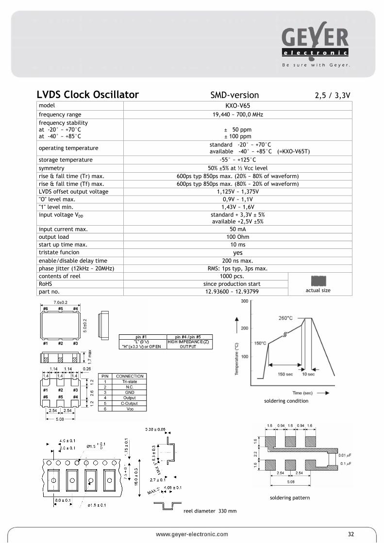
LVDS Clock Oscillator SMD-version 2,5 / 3,3V model KXO-V65 frequency range 19,440 ~ 700,0 MHz frequency stability at -20° ~ +70°C at -40° ~ +85°C
± 50 ppm ± 100 ppm
operating temperature standard -20° ~ +70°C available -40° ~ +85°C (=KXO-V65T)
storage temperature -55° ~ +125°C symmetry 50% ±5% at ½ Vcc level rise & fall time (Tr) max. 600ps typ 850ps max. (20% ~ 80% of waveform) rise & fall time (Tf) max. 600ps typ 850ps max. (80% ~ 20% of waveform) LVDS offset output voltage 1,125V ~ 1,375V "O" level max. 0,9V ~ 1,1V "1" level min. 1,43V ~ 1,6V input voltage VDD standard + 3,3V ± 5%
available +2,5V ±5% input current max. 50 mA output load 100 Ohm start up time max. 10 ms tristate funcion yes enable/disable delay time 200 ns max. phase jitter (12kHz ~ 20MHz) RMS: 1ps typ, 3ps max. contents of reel 1000 pcs. RoHS since production start part no. 12.93600 ~ 12.93799
32
soldering pattern
soldering condition
reel diameter 330 mm
actual size
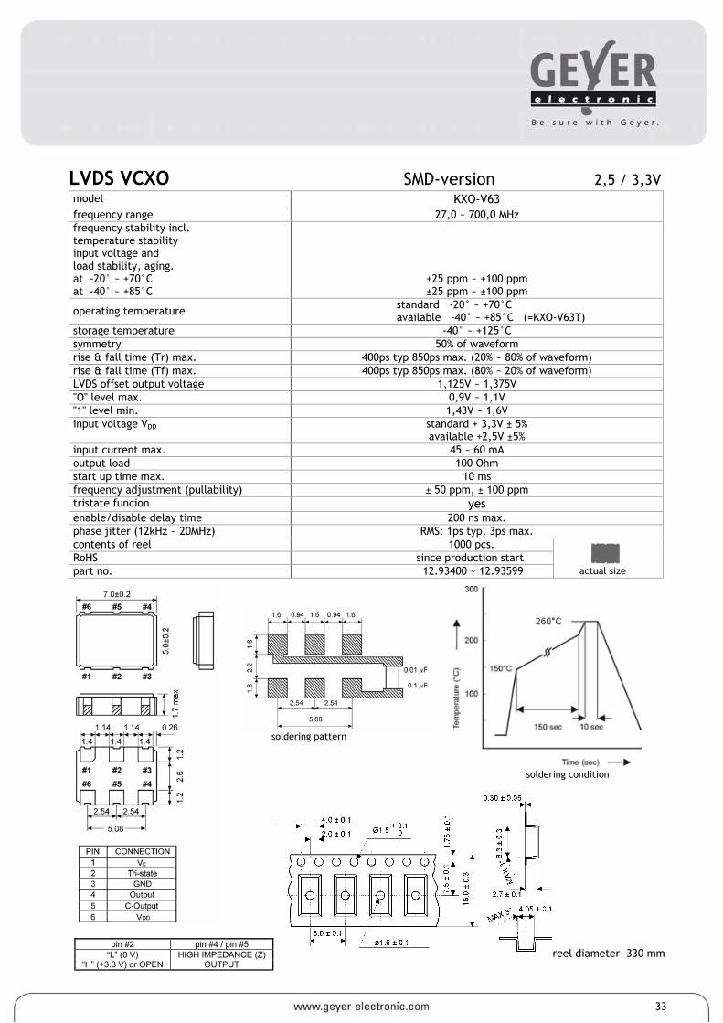
LVDS VCXO SMD-version 2,5 / 3,3V model KXO-V63 frequency range 27,0 ~ 700,0 MHz frequency stability incl. temperature stability input voltage and load stability, aging. at -20° ~ +70°C at -40° ~ +85°C
±25 ppm ~ ±100 ppm ±25 ppm ~ ±100 ppm
operating temperature standard -20° ~ +70°C available -40° ~ +85°C (=KXO-V63T)
storage temperature -40° ~ +125°C symmetry 50% of waveform rise & fall time (Tr) max. 400ps typ 850ps max. (20% ~ 80% of waveform) rise & fall time (Tf) max. 400ps typ 850ps max. (80% ~ 20% of waveform) LVDS offset output voltage 1,125V ~ 1,375V "O" level max. 0,9V ~ 1,1V "1" level min. 1,43V ~ 1,6V input voltage VDD standard + 3,3V ± 5%
available +2,5V ±5% input current max. 45 ~ 60 mA output load 100 Ohm start up time max. 10 ms frequency adjustment (pullability) ± 50 ppm, ± 100 ppm tristate funcion yes enable/disable delay time 200 ns max. phase jitter (12kHz ~ 20MHz) RMS: 1ps typ, 3ps max. contents of reel 1000 pcs. RoHS since production start part no. 12.93400 ~ 12.93599
33
soldering pattern
soldering condition
reel diameter 330 mm pin #2 pin #4 / pin #5
“L” (0 V) HIGH IMPEDANCE (Z) “H” (+3.3 V) or OPEN OUTPUT
actual size
actual size
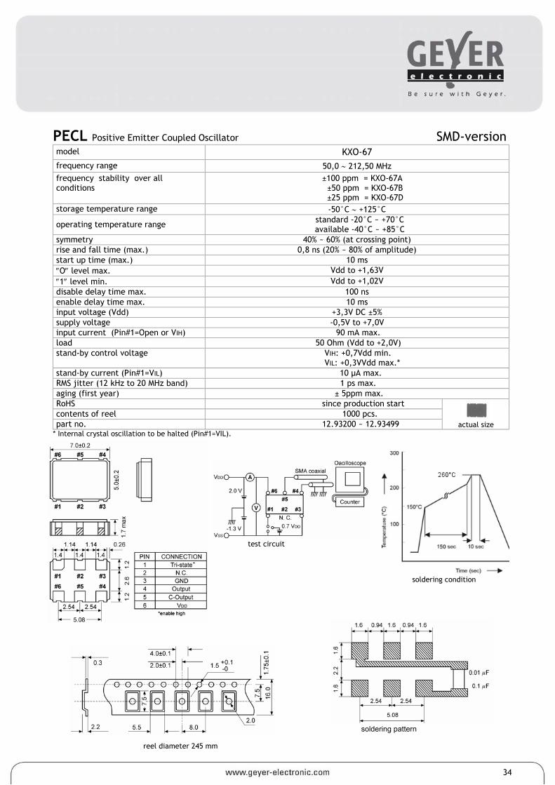
PECL Positive Emitter Coupled Oscillator SMD-version model KXO-67 frequency range 50,0 ∼ 212,50 MHz frequency stability over all conditions
±100 ppm = KXO-67A ±50 ppm = KXO-67B ±25 ppm = KXO-67D
storage temperature range -50°C ∼ +125°C
operating temperature range standard -20°C ~ +70°C available -40°C ~ +85°C
symmetry 40% ~ 60% (at crossing point) rise and fall time (max.) 0,8 ns (20% ~ 80% of amplitude) start up time (max.) 10 ms ″O″ level max. Vdd to +1,63V ″1″ level min. Vdd to +1,02V disable delay time max. 100 ns enable delay time max. 10 ms input voltage (Vdd) +3,3V DC ±5% supply voltage -0,5V to +7,0V input current (Pin#1=Open or VIH) 90 mA max. load 50 Ohm (Vdd to +2,0V) stand-by control voltage VIH: +0,7Vdd min.
VIL: +0,3VVdd max.* stand-by current (Pin#1=VIL) 10 µA max. RMS jitter (12 kHz to 20 MHz band) 1 ps max. aging (first year) ± 5ppm max. RoHS since production start contents of reel 1000 pcs. part no. 12.93200 ~ 12.93499
* Internal crystal oscillation to be halted (Pin#1=VIL).
34
soldering condition
soldering pattern
reel diameter 245 mm
test circuit
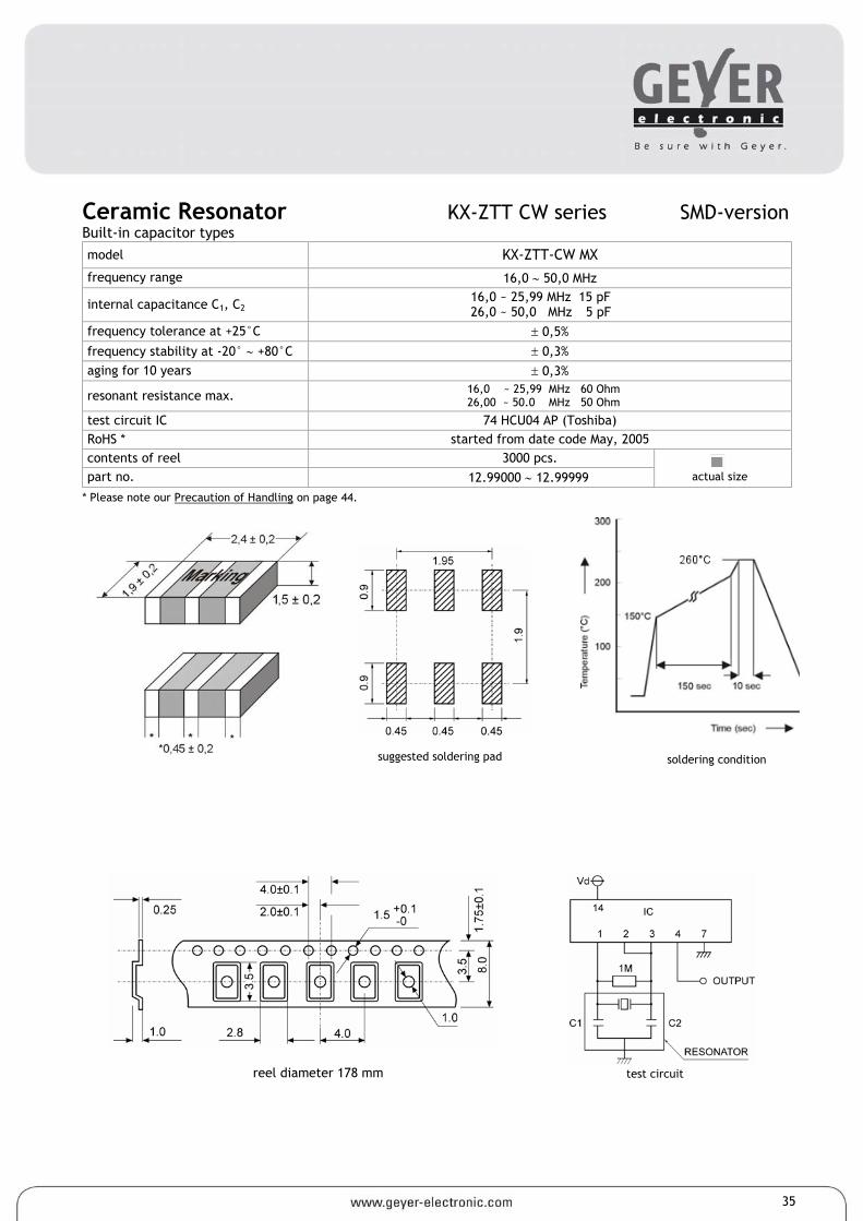
Ceramic Resonator KX-ZTT CW series SMD-version Built-in capacitor types model KX-ZTT-CW MX
frequency range 16,0 ∼ 50,0 MHz
internal capacitance C1, C2 16,0 ~ 25,99 MHz 15 pF 26,0 ~ 50,0 MHz 5 pF
frequency tolerance at +25°C ± 0,5%
frequency stability at -20° ∼ +80°C ± 0,3% aging for 10 years ± 0,3%
resonant resistance max. 16,0 ~ 25,99 MHz 60 Ohm 26,00 ~ 50.0 MHz 50 Ohm
test circuit IC 74 HCU04 AP (Toshiba) RoHS * started from date code May, 2005 contents of reel 3000 pcs. part no. 12.99000 ∼ 12.99999
* Please note our Precaution of Handling on page 44.
35
test circuit
reel diameter 178 mm
soldering condition
suggested soldering pad
actual size
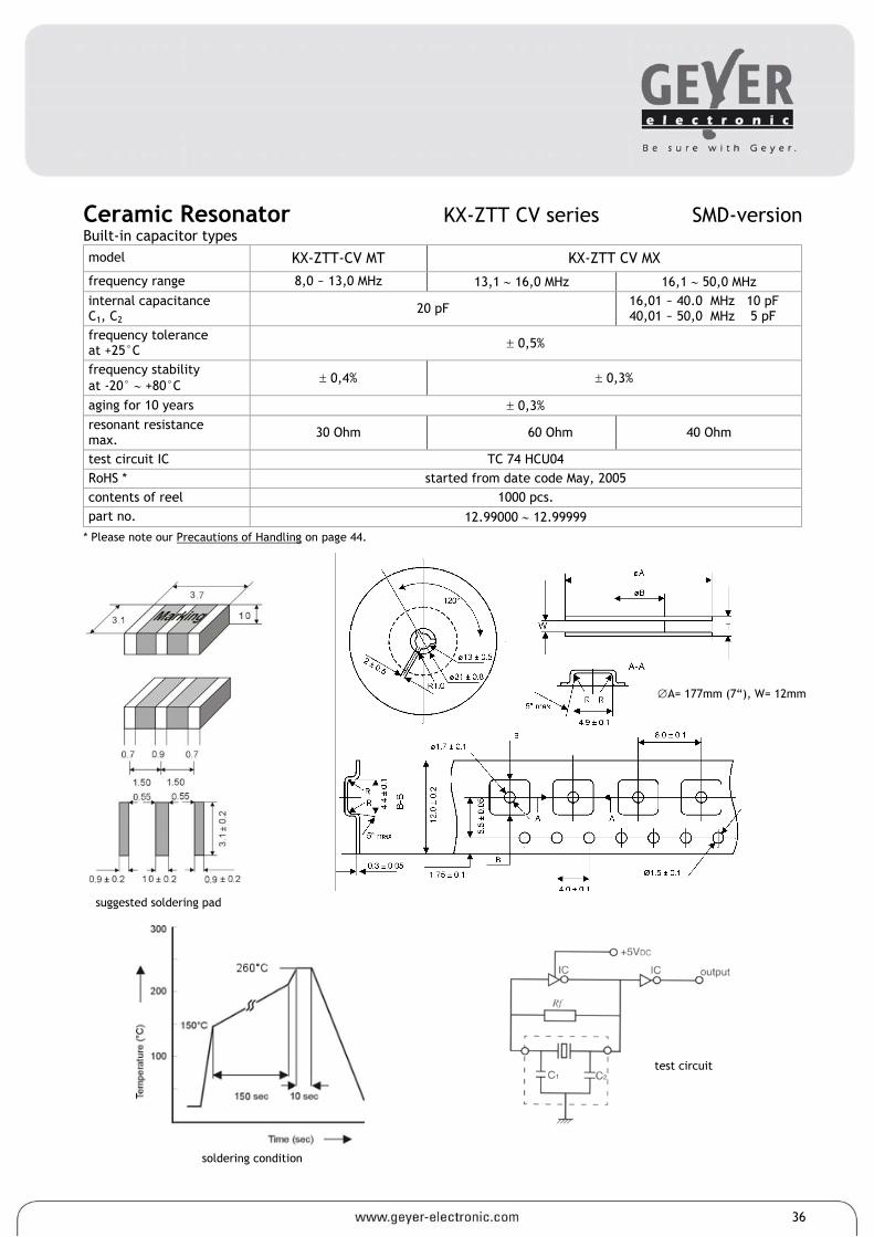
Ceramic Resonator KX-ZTT CV series SMD-version Built-in capacitor types model KX-ZTT-CV MT KX-ZTT CV MX
frequency range 8,0 ~ 13,0 MHz 13,1 ∼ 16,0 MHz 16,1 ∼ 50,0 MHz internal capacitance C1, C2
20 pF 16,01 ~ 40.0 MHz 10 pF 40,01 ~ 50,0 MHz 5 pF
frequency tolerance at +25°C ± 0,5%
frequency stability at -20° ∼ +80°C ± 0,4% ± 0,3%
aging for 10 years ± 0,3% resonant resistance max. 30 Ohm 60 Ohm 40 Ohm
test circuit IC TC 74 HCU04 RoHS * started from date code May, 2005 contents of reel 1000 pcs. part no. 12.99000 ∼ 12.99999
* Please note our Precautions of Handling on page 44.
test circuit
∅A= 177mm (7“), W= 12mm
suggested soldering pad
soldering condition
36
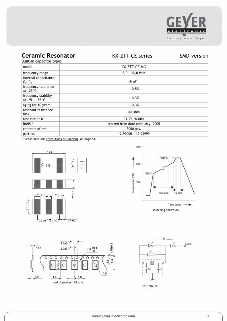
Ceramic Resonator KX-ZTT CE series SMD-version Built-in capacitor types model KX-ZTT-CE MG
frequency range 8,0 ~ 12,0 MHz internal capacitance C1, C2
15 pF
frequency tolerance at +25°C ± 0,5%
frequency stability at -25 ∼ +85°C ± 0,3%
aging for 10 years ± 0,3% resonant resistance max. 40 Ohm
test circuit IC TC 74 HCU04 RoHS * started from date code May, 2005 contents of reel 3000 pcs. part no. 12.99000 ~ 12.99999
* Please note our Precautions of Handling on page 44.
reel diameter 178 mm
test circuit
soldering condition
37
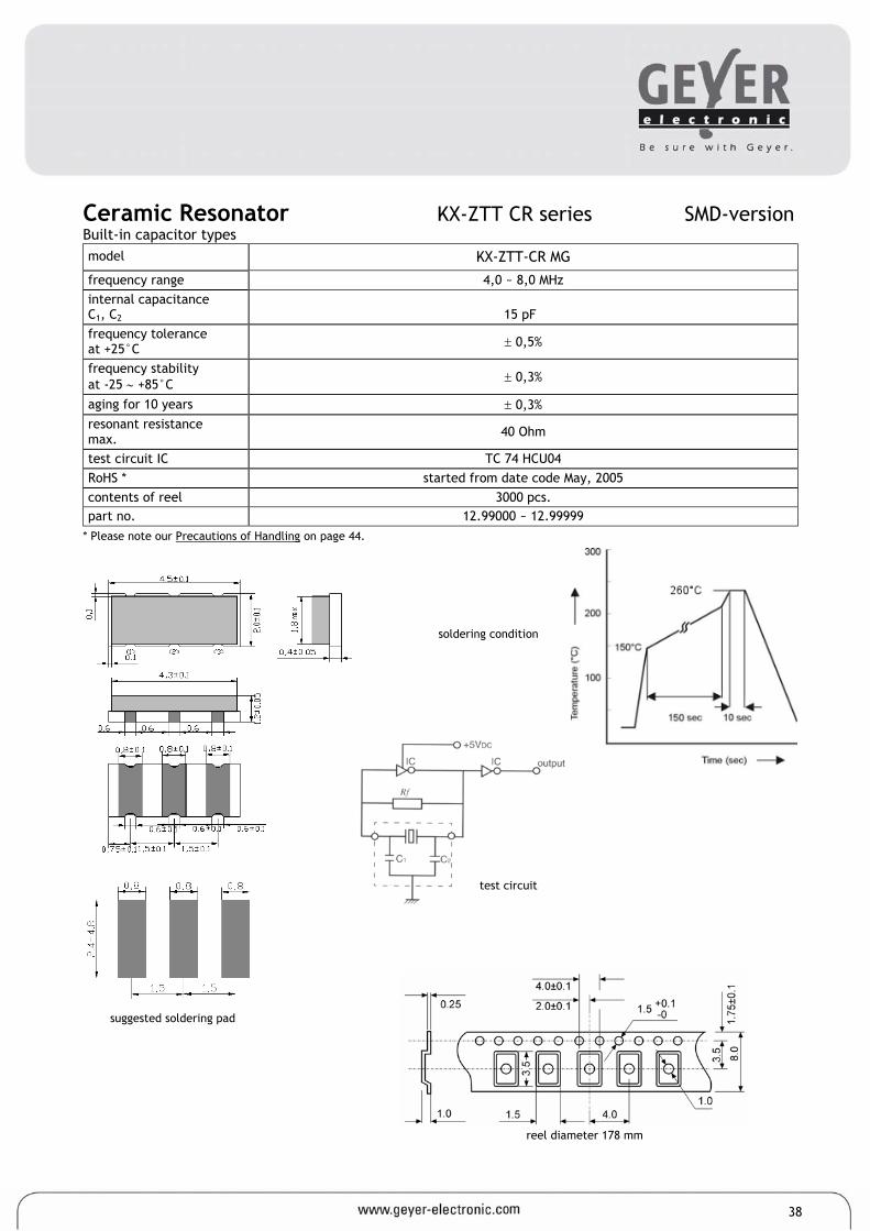
Ceramic Resonator KX-ZTT CR series SMD-version Built-in capacitor types model KX-ZTT-CR MG
frequency range 4,0 ~ 8,0 MHz internal capacitance C1, C2
15 pF
frequency tolerance at +25°C ± 0,5%
frequency stability at -25 ∼ +85°C ± 0,3%
aging for 10 years ± 0,3% resonant resistance max. 40 Ohm
test circuit IC TC 74 HCU04 RoHS * started from date code May, 2005 contents of reel 3000 pcs. part no. 12.99000 ~ 12.99999
* Please note our Precautions of Handling on page 44.
suggested soldering pad
soldering condition
reel diameter 178 mm
test circuit
38
Ceramic Resonators KX-ZTT C series SMD-version Built-in capacitor types model KX-ZTT CC MG
frequency range 1,84 ∼ 8,0 MHz internal capacitance C1, C2
1,84 ~ 2,40 MHz 33 pF 2,41 ~ 8,0 MHz 22 pF
frequency tolerance at +25°C ± 0,5%
frequency stability at -20° ∼ +80°C ± 0,3%
aging for 10 years ± 0,3%
resonant resistance max.
1,84 ~ 2,99 MHz 100 Ohm 3,00 ~ 3,49 MHz 50 Ohm 3,50 ~ 8,00 MHz 30 Ohm
test circuit IC CD 4069 UBPX2 RoHS * started from date code May, 2005 contents of reel 4000 pcs. part no. 12.99000 ∼ 12.99999
* Please note our Precautions of Handling on page 44.
soldering condition
test circuit
tape specification: ∅A= 330mm (13“), W= 16mm
suggested soldering pad
39
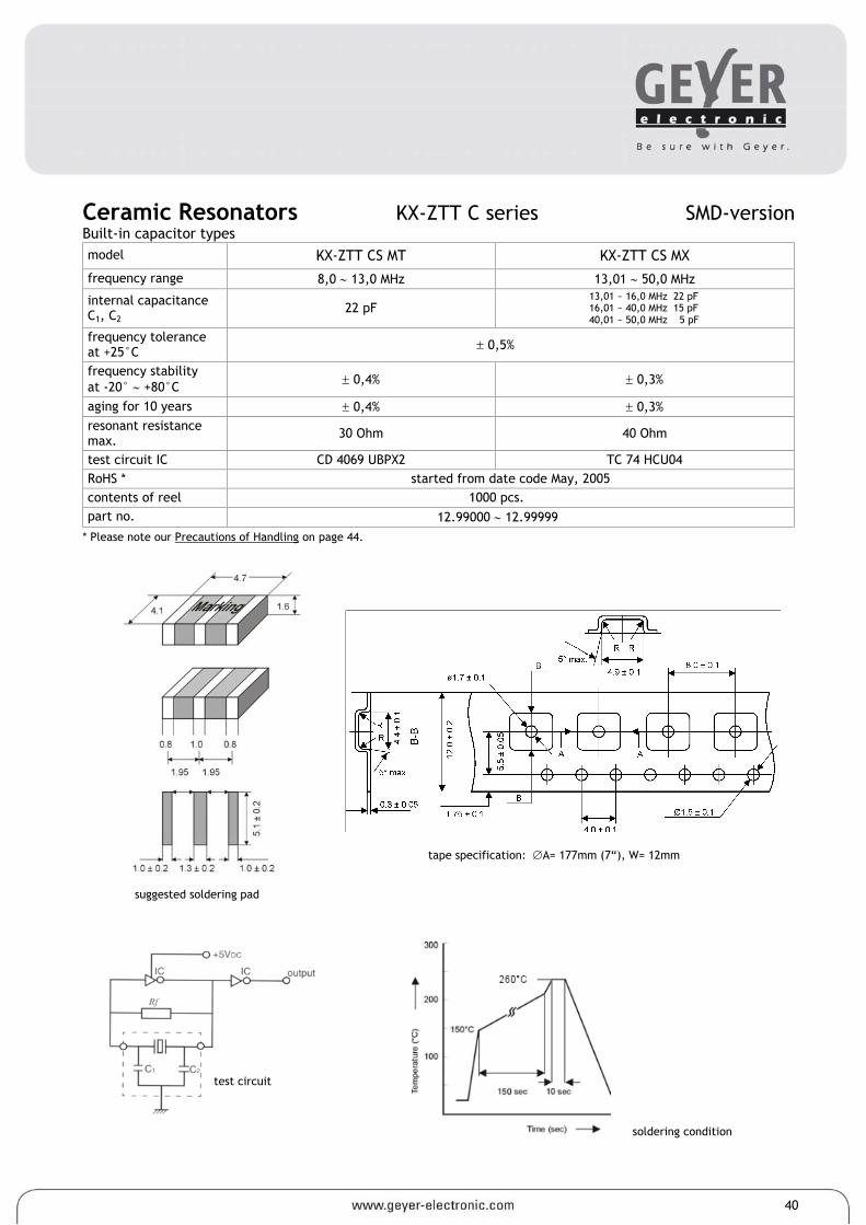
Ceramic Resonators KX-ZTT C series SMD-version Built-in capacitor types model KX-ZTT CS MT KX-ZTT CS MX
frequency range 8,0 ∼ 13,0 MHz 13,01 ∼ 50,0 MHz
internal capacitance C1, C2
22 pF 13,01 ~ 16,0 MHz 22 pF 16,01 ~ 40,0 MHz 15 pF 40,01 ~ 50,0 MHz 5 pF
frequency tolerance at +25°C ± 0,5%
frequency stability at -20° ∼ +80°C ± 0,4% ± 0,3%
aging for 10 years ± 0,4% ± 0,3% resonant resistance max. 30 Ohm 40 Ohm
test circuit IC CD 4069 UBPX2 TC 74 HCU04 RoHS * started from date code May, 2005 contents of reel 1000 pcs. part no. 12.99000 ∼ 12.99999
* Please note our Precautions of Handling on page 44.
soldering condition
test circuit
tape specification: ∅A= 177mm (7“), W= 12mm
suggested soldering pad
40
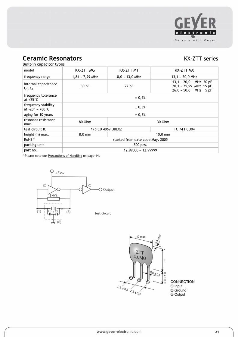
Ceramic Resonators KX-ZTT series Built-in capacitor types model KX-ZTT MG KX-ZTT MT KX-ZTT MX
frequency range 1,84 ∼ 7,99 MHz 8,0 ∼ 13,0 MHz 13,1 ∼ 50,0 MHz
internal capacitance C1, C2
30 pF 22 pF 13,1 ~ 20,0 MHz 30 pF 20,1 ~ 25,99 MHz 15 pF 26,0 ~ 50.0 MHz 5 pF
frequency tolerance at +25°C ± 0,5%
frequency stability at -20° ∼ +80°C ± 0,3%
aging for 10 years ± 0,3% resonant resistance max. 80 Ohm 30 Ohm
test circuit IC 1/6 CD 4069 UBEX2 TC 74 HCU04 height (h) max. 8,0 mm 10,0 mm RoHS * started from date code May, 2005 packing unit 500 pcs. part no. 12.99000 ∼ 12.99999
* Please note our Precautions of Handling on page 44.
test circuit
41
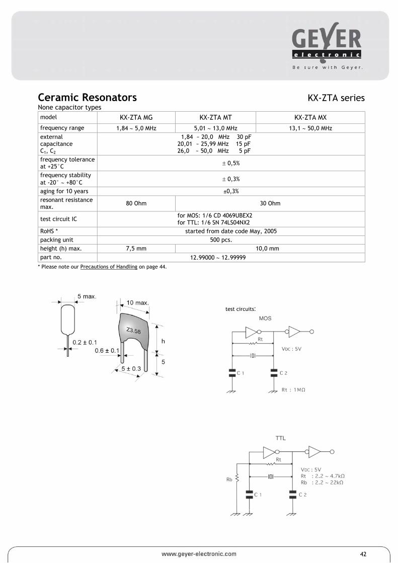
Ceramic Resonators KX-ZTA series None capacitor types model KX-ZTA MG KX-ZTA MT KX-ZTA MX
frequency range 1,84 ∼ 5,0 MHz 5,01 ∼ 13,0 MHz 13,1 ∼ 50,0 MHz external capacitance C1, C2
1,84 ~ 20,0 MHz 30 pF 20,01 ~ 25,99 MHz 15 pF 26,0 ~ 50,0 MHz 5 pF
frequency tolerance at +25°C ± 0,5%
frequency stability at -20° ∼ +80°C ± 0,3%
aging for 10 years ±0,3% resonant resistance max. 80 Ohm 30 Ohm
test circuit IC for MOS: 1/6 CD 4069UBEX2 for TTL: 1/6 SN 74LS04NX2
RoHS * started from date code May, 2005 packing unit 500 pcs. height (h) max. 7,5 mm 10,0 mm part no. 12.99000 ∼ 12.99999
* Please note our Precautions of Handling on page 44.
test circuits:
42
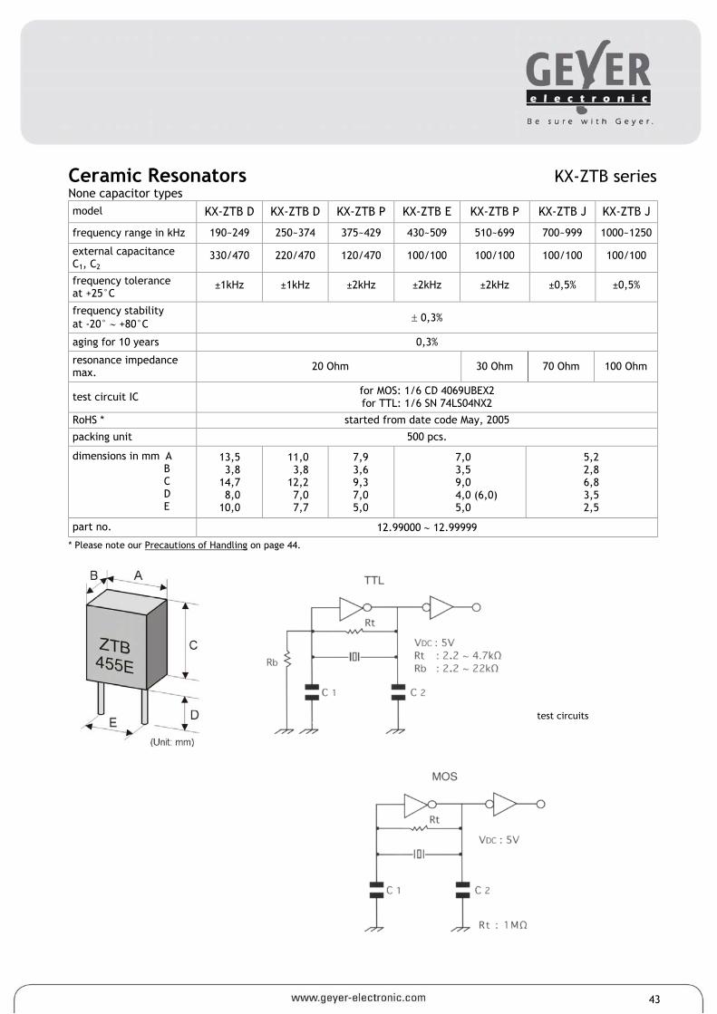
Ceramic Resonators KX-ZTB series None capacitor types model KX-ZTB D KX-ZTB D KX-ZTB P KX-ZTB E KX-ZTB P KX-ZTB J KX-ZTB J
frequency range in kHz 190~249 250~374 375~429 430~509 510~699 700~999 1000~1250
external capacitance C1, C2
330/470 220/470 120/470 100/100 100/100 100/100 100/100
frequency tolerance at +25°C
±1kHz ±1kHz ±2kHz ±2kHz ±2kHz ±0,5% ±0,5%
frequency stability at -20° ∼ +80°C ± 0,3%
aging for 10 years 0,3%
resonance impedance max. 20 Ohm 30 Ohm 70 Ohm 100 Ohm
test circuit IC for MOS: 1/6 CD 4069UBEX2 for TTL: 1/6 SN 74LS04NX2
RoHS * started from date code May, 2005
packing unit 500 pcs.
dimensions in mm A B C D E
13,5 3,8
14,7 8,0
10,0
11,0 3,8
12,2 7,0 7,7
7,9 3,6 9,3 7,0 5,0
7,0 3,5 9,0 4,0 (6,0) 5,0
5,2 2,8 6,8 3,5 2,5
part no. 12.99000 ∼ 12.99999
* Please note our Precautions of Handling on page 44.
test circuits
43

CERAMIC RESONATORS Precautions for Handling 1. Precautions for Safety.
1.1 Fail-Safe Design for Equipment in application of the Ceramic Resonators (Chip Type), it is recommended that equipment shall be protected by adding a protective and/or retardant design circuit against deteriorations and failures of the Ceramic Resonators. 1.2 Operating Temperature Ranges. The Ceramic Resonators (Chip Type) shall not be operated beyond the specified „Operating Temperature Range“ in the Catalogue or the Specifications. 1.3 Changes/Drifts in Oscillating Frequency. It shall be noted that oscillating frequencies of the Ceramic Resonators (Chip Type) may drift depending IC applied (the type names, the manufacturer) and capacitance values of external capacitors C1* and C2* and the circuit design. Note *Refer to „Standard Test Circuit Diagram“ in the Catalogue or the individual Specification. 1.4 Abnormal Oscillation. The Ceramic Resonators (Chip Type) are always accompanied by superior resonances. Hence in the circuit, supe- rior oscillations or stop of oscillation may occur depending on the circuit design (IC applied, frequency characteristics of the IC, supply voltage etc.) and/or environmental conditions. Attention shall be paid to those abnormalities above mentioned in circuit design. 1.5 Stray Capacitance. Stray capacitances and insulation resistances on printed circuit board may cause abnormalities of the Ceramic Resonators such as „higher harmonic oscillations“ or „stop of oscillation“ Attention shall be paid to those abnormalities above men- tioned in Circuit design. 1.6 Matching Capacitors. In application of the Ceramic Resonators (Chip Type), two selected capacitors** shall be added for constructing „Colpitts Oscillation Circuit“. Note **The capacitance values are specified in the Catalogue. 2. Prohibited Applications 2.1 „Flow Soldering“ shall not be applied to the Ceramic Resonators (Chip Type). 2.2 „Ultrasonic Cleaning“ and „Ultrasonic Welding“ shall not be applied to the Ceramic Resonators (Chip Type) for preventing them from electrical failures and mechanical damages. 2.3 Lacquer shall not be applied to resonator types KX-ZTT CC and KX-ZTT CR. 3. Application Notes 3.1 Overvoltages Spikes & Electrostatic Discharges Abnormal/excess electrical stresses such as over voltage spikes and electrostatic dis- charges may cause electrical deteriorations and failures of the Ceramic Resonators and affect reliability of the devices. 3.2 Abnormal Mechanical Stresses. (1) Abnormal/excess mechanical stresses such as falling shocks shall not be applied to the Ceramic Resonators (Chip Type) in handling to prevent them form being damaged or cracked. (2) Dropped devices shall not be used. 3.3 Surface Mounting Consideration. In automated mounting of The Ceramic Resonators (Chip Type) on printed circuit boards, any bending expanding and pulling forces or shocks against the Ceramic Resonators (Chip Type) shall be kept minimum to prevent them from elec- trical failures and mechanical damages of the devices. 3.4 Soldering (Reflow). (1) Solderings of The Ceramic Resonators (ChipType) shall conform to the soldering conditions in the individual Specifications. (2) The Resonators are designed for „Reflow Soldering“. (3) In the reflow solderings, too high soldering temperatures and too large temperature gradient such as rapid heating or cooling may cause electrical failures and mechanical damages of the devices. 3.5 Soldering Flux. a) Resin-based and non-activated soldering flux is recommended. b) The content of halogen in the flux shall be 0,1 wt.% or less. 3.6 Post Soldering Cleaning. (1) Application of ultrasonic cleaning is prohibited. (2) Cleaning Conditions such as kinds of cleaning solvents, immersion time and temperatures etc. shall be checked by experiments before production. 3.7 Operating and Storage Conditions. The Ceramic Resonators (Chip type) shall not be operated and/or stored under following environ- mental conditions. a) To be exposed directly to water or salt water b) To be exposed directly to sun-light c) Under conditions of dew formation d) Under conditions of corrosive atmosphere such as hydrogen sulfide, sulfurous acid, chlorine and ammonia. 3.8 Long Term Storage. The Ceramic Resonators (Chip Type) shall not be stored under severe conditions of high temperatures and high humidities. Store them indoors under 40°C max. and 75% RH max. Use them within one year and check.
4. Lead-free procedure recommendation
5. Application notice of SMD products:
PCB broad bending will cause the part fall off
Reflow of high soldering temperature district: 260°C max., 10s max.
Manual soldering recommendation: Temperature of soldering iron is 270±5°C, putting the soldering iron on the equipment of 0.5mm high. Moreover, putting the dissolved soldering on the electrode for 3±1s.
*The Resonator will be unstable and lose function if the above soldering temperature is overheated.
PCB soldering point should be satisfied with requirement of specification recommendation: Otherwise, the accurate level of soldering point will be lower, parts may fall off. Parts may fall off if PCB winding is overlarge.
6. Application notice of SMD products with SMD mounting machines. Since our products are Ceramic parts, please do not put too much mechanical pressure on the parts. We suggest using Mounting Machine of optical positioning rather than that of mechanical positioning. Damage of parts will happen if mechanical force is too large. Please estimate clearly on mounting before use.
The metallic part should be soldered fully otherwise the part may be fallen off
44
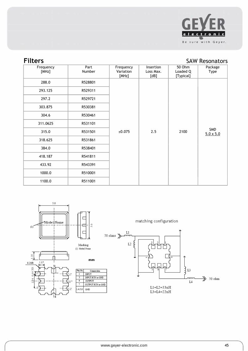
Filters SAW Resonators Frequency
[MHz] Part
Number Frequency Variation
[MHz]
Insertion Loss Max.
[dB]
50 Ohm Loaded Q [Typical]
Package Type
288.0 R528801
293.125 R529311
297.2 R529721
303.875 R530381
304.6 R530461
311.0625 R531101
315.0 R531501
318.625 R531861
384.0 R538401
418.187 R541811
433.92 R543391
1000.0 R510001
1100.0 R511001
±0.075 2.5 2100 SMD 5.0 x 5.0
45
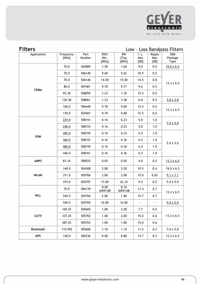
Filters Low – Loss Bandpass Filters Application Frequency
[MHz] Part
Number BW3 Min.
[MHz]
BW 3Typ. [MHz]
I. L. Max [dB]
Ripple Max [dB]
SMD Package
Type
70.0 504089 1.50 1.60 9.6 0.5 19.0 x 6.5
70.0 506140 9.60 9.62 10.9 0.5
70.0 506146 14.50 15.00 14.5 0.8
80.0 507401 9.70 9.77 9.6 0.5
95.38 508055 1.23 1.35 15.5 0.5
13.3 x 6.5
130.38 508061 1.23 3.38 6.8 0.5 3.8 x 3.8
160.0 506440 9.70 9.80 15.5 0.5
CDMA
170.0 507601 9.70 9.80 15.5 0.5 13.3 x 6.5
225.0 508151 0.16 0.23 5.0 1.0
246.0 508153 0.16 0.23 5.0 1.0 7.0 x 5.0
282.0 508155 0.16 0.23 6.5 1.0
360.0 508157 0.16 0.36 6.5 1.0
400.0 508159 0.16 0.36 6.5 1.0
GSM
440.0 508161 0.16 0.36 6.5 1.0
5.0 x 5.0
AMPS 83.16 508253 0.03 0.05 4.0 0.5 13.3 x 6.5
140.0 504308 3.00 3.20 19.5 0.4 19.0 x 6.5
371.0 505706 2.00 2.08 15.0 0.65 9.1 x 7.1 WLAN
374.0 505707 17.00 22.10 9.5 0.5 5.0 x 5.0
70.0 506139 8.00 @BW1dB
8.10 @BW1dB 11.4 0.7
549.5 505704 2.00 1.80 15.7 0.7 13.3 x 6.5
WLL
549.5 505705 10.00 16.00 - - 5.0 x 5.0
169.25 505605 1.00 2.00 7.7 0.5
337.25 505702 1.00 2.00 15.0 0.6 CATV
487.25 505703 1.00 1.80 15.0 0.6
13.3 x 6.5
Bluetooth 110.592 505606 1.10 1.15 11.5 0.3 7.0 x 5.0
GPS 140.0 506336 9.60 8.80 13.7 0.3 13.3 x 6.5
46
Filters RF SAW Filters Frequency
[MHz] Part
Number Inbandwidth [MHz Min.]
I. L. Max. [MHz]
Ripple Max. [dB]
Attenuation Min. [dB]
Impedance [Ohm//L,C]
SMD Package
Type
139.0 F51398 8 6.5 2.0 40 210//Tuning
147.0 F51478 8 6.5 2.0 40 210//Tuning
155.0 F51558 8 6.5 2.0 40 210//Tuning
165.0 F51658 8 6.5 2.0 40 210//Tuning
171.0 F51718 8 6.5 2.0 40 210//Tuning
273.0 F52734 4 4.5 1.5 55 50//0
281.0 F52816 6.4 4.5 1.5 55 150//0
325.3 F53256 6.6 4.5 1.5 55 150//0
5.0 x 5.0
410.0 F54104 4 3.5 1.0 55 150//0
412.0 F54124 4 3.5 1.0 55 150//0
419.0 F54194 4 3.5 1.0 55 150//0
434.0 F54344 4 3.5 1.0 55 50//0
446.0 F54464 4 3.5 1.0 55 150//0
448.0 F54484 4 3.5 1.0 55 150//0
450.0 F54504 4 3.5 1.0 55 150//0
454.0 F54544 4 3.5 1.0 55 150//0
458.0 F54584 4 2.5 1.0 55 150//0
458.0 F54588 8 4.5 1.0 55 150//0
462.0 F54624 4 3.5 1.0 55 150//0
465.0 F54654 4 3.5 1.0 55 150//0
465.0 F54655 4 3.5 1.0 55 50//0
466.0 F54664 4 3.5 1.0 55 150//0
478.0 F54784 4 3.5 1.0 55 150//0
3.8 x 3.8
841.0 F58414 4 3.5 1.5 55 50//0
897.5 F58973 35 3.5 1.5 45 50//0
902.5 F59023 35 3.5 1.5 45 50//0
1000.0 F1G020 20 5 1.5 40 50//0
1100.0 F1G120 20 5 1.5 40 50//0
3.0 x 3.0
47
GEYER ELECTRONIC Lochhamer Schlag 5 82166 Gräfelfing/München Tel. 089/546868-0 Fax 089/546868-91 [email protected] www.geyer-electronic.de
General Terms and Conditions of Sale of GEYER ELECTRONIC e.K. (Rev. 05/2007)
I.Scope of Validity 1.These Conditions shall apply exclusively to all our offers, supplies and services to our Customer. These Conditions shall also apply for future orders, supplies and services without the need of any express agreement thereon at the conclusion of such transaction. 2.Any conditions of the Customer, which differ from our Conditions shall not be recognized, whether or not we have objected to such conditions. Our Conditions shall also apply, if we, knowing of any contradictory or dissenting conditions of our Customer, unconditionally execute the supply. 3.Our Conditions shall apply only to contractors as defined by § 310, Section 1 BGB (German Civil Code).
II.Offer and Acceptance 1.Our quotations are subject to change without notice and are not binding unless they are expressly described as being binding. 2.Any describing data of our products, such as illustrations, drawings, specifications, weights, dimensions, performance-, operational- and consumption data, loading capacities, tolerances, and information relating to the use or suitability for a particular application, contained in our offer, in prospectus, catalogues or similar documents, constitute an approximate guide and shall not be binding unless expressly described as binding. Any such data relate to serial products which have been tested under central European operation conditions and describe their standard functions. They are not to be deemed guaranteed properties but are descriptions or definitions of the goods or services. 3.Customary changes in quantities, quality or specifications of the goods, changes as a result of a change of law and technical improvements shall be allowed. We may also replace parts of the goods with other equal parts provided such parts do not impair their suitability for the purpose provided for by the contract. 4.We reserve the right of ownership and copyright of all quotation documents; they may not be made available to third parties unless upon our approval. 5.Offers made by the Customer shall be in writing (letter, telefax, e-mail). 6.We may accept an order made by a Customer within 4 weeks after its receipt, which shall be confirmed in writing.
III.Prices and Terms of Payment 1.The prices quoted by us are in EURO and are given on the basis of carriage paid (CPT as per Incoterms 2000) to the destination stated by the Customer for deliveries within Germany, subject to the provisions under Section IV.2 hereunder. Where the goods are supplied for export from Germany, the price basis shall be Ex Works (EXW as per Incoterms 2000). Value added tax shall be added at the rate applicable at the time of invoicing. 2.Unless otherwise agreed, the price shall be paid for goods delivered within Germany within 10 calendar days with a discount of 3 % and for deliveries for export within 30 calendar days (without discount). 3.If the Customer is in delay in making payment, we are entitled to charge interest for late payment at the rate of 8 % p.a. above the relevant base rate of the Deutsche Bundesbank. If we are able to demonstrate a greater loss as a result of late payment, then we are entitled to claim for this loss. 4.Any offsetting or retaining of payment by the Customer is only permitted if Customer`s counterclaims are not contested or have been finally decided by the court.
IV.Delivery 1.Deliveries within Germany shall be made CPT (according to Incoterms 2000) to the destination stated by the Customer, subject to the provisions in Section IV.2 hereunder, and for deliveries for export EXW (according to Incoterms 2000). We are entitled to make partial deliveries. At the request of the Customer, the deliveries will be insured by us at his expense. 2.The means of shipment shall be at our discretion. We will deliver in customary packaging. We will make deliveries up to an order value of EURO 499,- (without VAT) for a lump sum packaging- and shipping cost surcharge of EURO 6,90 per parcel with a weight of up to 10 kg and for a surcharge of EURO 18,-- in case of pallet consignment. In case of excess weights the surcharge shall be billed according to the actual cost. Deliveries exceeding an order value of EURO 500,- shall be made without surcharge. 3.We are entitled to charge the Customer for costs incurred by us due to Customer`s failure to accept the goods or because of false information given by him. 4.The minimum order value for shipments shall be EURO 25,- (without VAT).
V.Transfer of Risk 1.The risk of accidental loss and accidental deterioration of the goods passes to the Customer when the goods are handed over to him, to the carrier or to such other party in charge of the transport. 2.If the delivery is delayed due to circumstances for which the Customer is responsible for, the risk passes over to him from the date of readiness for shipment.
VI.Transportation Damages 1.The Customer shall give notice in writing without delay to us as well as to the carrier or such other party in charge of the transport of any transport damage within the following time-limits :
In case of damaged packaging : a) Mail :The damage needs to be confirmed upon handing over and to be notified at the post office within 24 hours (!). The damage needs to be notified to us within 48 hours. b) Parcel Post :The damaged goods need to be unpacked in the presence of the driver and the damage needs to be confirmed by him. The damage is to be notified to us within 48 hours. c) Transport: The damaged goods need to be unpacked in the presence of the driver and the damage needs to be confirmed on the bill of lading. The damage is to be notified to us within 48 hours.
In case of undamaged packaging : a) Mail: Immediately (within 24 hours) the post office in charge needs to be notified and an inspection and a finding of facts is to be applied for. The damage is to be notified to us within 48 hours. b) Parcel Post: The damage is to be notified to us within 48 hours. c) Transport :The damaged goods need to be unpacked in the presence of the driver and the damage needs to be confirmed on the bill of lading, indicating that the packaging has been undamaged prior to the ascertainment of the damage. The damage is to be notified to us within 48 hours.
VII.Delivery Time 1.Compliance with the agreed due dates for delivery requires that the Customer has fulfilled all his obligations in good time and in the appropriate way. 2.The delivery time has been complied with if by the end of the delivery period, the ordered goods have been handed over to the Customer, or the carrier or the other party in charge of the transport, or is ready for shipment and this has been notified to the Customer. 3.If non-compliance with an agreed delivery period is due to force majeure or other circumstances for which we are not responsible, the delivery period will be extended by the duration of such events. 4.If a delivery is in delay due to circumstances for which we are responsible for, or becomes impossible, our liability for damages shall be limited in accordance with the provisions of Section X hereunder.
VIII.Retention of Title 1.The property of all goods supplied shall remain with us until all amounts outstanding to us under the business relationship with the Customer are fully paid. In the event of a breach of contract by the Customer, especially in case of default of payment or in case of enforcement measures by third parties, we are entitled to demand return of the goods. Return of the goods or their seizure shall not be deemed termination or cancellation of the contract, unless we have expressly declared so. We are entitled to the sale or any other use or exploitation of such returned goods.
48
GEYER ELECTRONIC Lochhamer Schlag 5 82166 Gräfelfing/München Tel. 089/546868-0 Fax 089/546868-91 [email protected] www.geyer-electronic.de
2.The Customer may neither pledge nor assign the goods by way of security. The Customer shall notify us immediately in the event of seizures of or other enforcement measures by third parties to the goods. 3.The Customer is entitled to resell the goods in the ordinary course of business. Once the goods are resold, payment claims by the customer against his own buyer as a result of the resale are deemed to have been assigned to us, whether or not such goods have been incorporated into, processed or mixed with other goods. We herewith accept such assignment. Upon assignment the Customer shall be entitled to collect any receivables arising from the resale of the goods. We reserve our right to collect such receivables by ourselves in case the Customer fails to fulfil his payment obligations. 4.Any processing of the goods shall always be made in our name and for our behalf. In case the goods are incorporated into or mixed with other goods not belonging to us, we will become the co-owner of such other goods in relation of the value of our goods to the value of the other goods. 5.We undertake to release the securities due to us at the request of the Customer in so far as their value exceed the secured debts by more than 20 %, in so far as these have not yet been settled.
IX.Liability for Defects 1.We accept liability for defects of the goods or services supplied only if the Customer has complied with his legal inspection and notification duties. The Customer shall inspect the goods without delay upon delivery and shall give notice to us of any defect without delay. If the Customer fails to give such notice, the goods shall be conclusively accepted, except for a defect which has not been detectable during inspection. 2.In case of a defect, we shall make good such defect at our option by repair or by the supply of a replacement. In case of repair we will bear all expenses necessary for such repair, except those expenses which are the result of the goods being transferred to another location than the place of performance agreed upon. 3.If repair or replacement is unsuccessful, the Customer is entitled, at his option, to demand a corresponding reduction in the purchase price or cancellation of the contract. 4.No claims for defects can be made in case of minor deviations from the properties agreed upon or in case of a minor impairment of the suitability, in case of normal wear and tear, in case of damages resulting from misuse, use of unsuitable operating materials, in case of external influences, which have not been agreed upon or have not been a condition of the contract, or in case of defects of the software which cannot be reproduced. 5.This liability for defects does also not apply if the Customer modifies the goods without our consent or has them modified by third parties and such modification makes the remedy more difficult or impossible. In either case the Customer shall be liable for the additional expenses incurred due to such modification. 6.In case of defects in goods as are not of our manufacture, we are entitled at our option to pursue our warranty claims against the manufacturer or supplier of such goods or to assign such claims to our Customer. The Customer may claim against us in case of such defects only, if Customers claim against the supplier or manufacturer has been unsuccessful or, for instance due to insolvency, is unpromissing. 7.Claims for defects hereunder are always subject to the return of defective parts by the Customer to us. 8.The defects liability period is one (1) year from delivery of the goods. 9.Used goods are sold without any liability for defects. 10.We are not giving the Customer any guarantees within the legal meaning of the word, unless we expressly grant such a guarantee in a given case. 11.The provisions under Section X – Liability apply to any claims for damages by the Customer.
X.Liability 1.Our liability for damages or compensation, irrespective of the legal ground, in particular with respect to impossibility of performance, delays, defective of false supply, breach of contract, defective or non performed consulting or information, breach of duties in negotiations and wrongful acts, in so far as negligence is legally required, shall be limited to the extent set forth in this Section X. 2.We shall not be liable in case of ordinary negligence on the part of our managing director, legal representatives, executives or other agents. 3.We are liable under the legal provisions, if the damage was caused by negligent breach of a major contractual obligation (cardinal obligation); in such a case our liability for compensation shall be limited to the foreseeable damage that may typically occur. Cardinal obligations are understood to be obligations, which are mandatory for the proper performance of the contract and upon which the Customer could rely upon on a regular basis. 4.The foregoing limitations and exclusions of liability shall not apply in case of guaranteed properties, not in case of physical injuries or damage to health or loss of life for which we are responsible for and shall also not apply for claims made by the Customer under product liability.
XI.Waste Disposal under the German Electrical and Electronic Appliances Act 1.If the goods are subject to the German Electrical and Electronic Appliances Act, we offer to our Customer the option to carry out for him the waste disposal as stipulated by law. This service is provided against reimbursement of the actual cost that have been incurred and on condition that it has been requested in writing at the time of the purchase contract. Otherwise the Customer himself shall be liable for the correct legally stipulated waste disposal of the delivered goods at his own expense upon the termination of use of the goods. 2.In such a case the Customer shall indemnify us and our suppliers against any duties arising from section 10 II of the German Electrical and Electronic Appliances Act (Reacceptance Duty of the Manufacturer) and thus also against any associated third-party claims. 3.The Customer shall impose a contractual commitment on any third-party contractor to which he passes on the delivered good, specifying that the third party shall, at its own expense, ensure the correct legally stipulated waste disposal of the delivered good upon termination of use and that the third party shall furthermore impose the same commitment on further third parties in case that the relevant goods are passed on further. If the customer fails to impose a waste disposal commitment and a passing-on duty in respect of this commitment in his relationship with third-party contractors to which he passes on the delivered goods, then the Customer shall be liable to reaccept the delivered goods upon termination of use at his own expense and to ensure correct legally stipulated waste disposal of the same. If the Customer passes on the goods to non contractors, then the provisions of Section XI.2 hereabove shall apply. 4.Our claim towards Customer for take-over/indemnification shall not become subject to statute-barring until the expiration of two years following the final termination of use of the goods. This period shall start no earlier than our receipt of written notification from the Customer and/or from the Customer`s customer concerning termination of use.
XII.Final Provisions 1.In the case of disputes arising out of the business relationship with contractors, Munich is agreed as the legal venue, or, at our option, the principal place of business of our Customer. 2.Unless otherwise agreed, the place of performance is Munich. 3.The laws of the Federal Republic of Germany shall apply. The provisions of the United Nations Convention on Contracts for the International Sale of Goods do not apply. GEYER ELECTRONIC e.K. This catalogue replaces all former catalogue. All specifications represent the latest technical information and are subject to change without notice. For current update please refer to www.geyer-electronic.com. All rights are reserved by GEYER ELECTRONIC. No part of this publication may be reproduced for commercial purpose without permission from GEYER ELECTRONIC. Edition 11/2008
49
Fax order sheet for samples free of charge to GEYER ELECTRONIC Fax no. ++49/+89/546868-91 Company address:
Name: Department: Telefon no. Fax no. A) Please send me a sample with standard specification from your catalogue with the
following frequency: Order-no.: Type: Frequency: Project name: Scheduled quantity:
B) Please find attached a specification of a crystal/oscillator and contact us in order
to discuss the possibility of samples.
Project name:
Scheduled quantity:
Date Signature