QUARTIC Front-end Readout – Initial Steps James Pinfold For the QUARTIC Working Group René...
26
QUARTIC Front-end QUARTIC Front-end Readout – Initial Readout – Initial Steps Steps James Pinfold James Pinfold For the QUARTIC For the QUARTIC Working Group Working Group René Magritte: Empire of Light
-
Upload
jack-foley -
Category
Documents
-
view
222 -
download
2
Transcript of QUARTIC Front-end Readout – Initial Steps James Pinfold For the QUARTIC Working Group René...

QUARTIC Front-end Readout QUARTIC Front-end Readout – Initial Steps– Initial Steps
James PinfoldJames PinfoldFor the QUARTIC Working For the QUARTIC Working
GroupGroup
René Magritte: Empire of Light

The QUARTIC Working GroupThe QUARTIC Working Group
• University of Alberta: University of Alberta: Lars Holm, Lars Holm, James PinfoldJames Pinfold, , Drew Price, Jan Schaapman, Yushu YaoDrew Price, Jan Schaapman, Yushu Yao
• Fermilab:Fermilab: Mike Albrow Mike Albrow
• University of Texas at Arlington:University of Texas at Arlington: Andrew BrandtAndrew Brandt, , Chance Harenza, Joaquin Noyola, Pedro DuarteChance Harenza, Joaquin Noyola, Pedro Duarte
Associated GroupAssociated Group
• University of Louvain:University of Louvain: Krzysztof Piotrzkowski Krzysztof Piotrzkowski
James Pinfold Arlington Meeting April 2006James Pinfold Arlington Meeting April 2006

Initial Conception of QuarticInitial Conception of Quartic
• AIM: Use a precise ToF Cerenkov detector to match z(vertex) with AIM: Use a precise ToF Cerenkov detector to match z(vertex) with central track vertex and thus reduce backgrounds to, for example, central track vertex and thus reduce backgrounds to, for example, exclusive diffractive Higgs productionexclusive diffractive Higgs production
• Z of interaction = c(TR-TL)/2 where TR(TL) is the time measured in Z of interaction = c(TR-TL)/2 where TR(TL) is the time measured in the RHS(LHS) QUARTIC detectors (420m from IP) -the RHS(LHS) QUARTIC detectors (420m from IP) -
• We havez (mm) =0.21 t (psec) (2.1 mm for t=10 ps [ct/√2])
TL TR
TL
TR
z_vtx
z
t
X
We are aiming for We are aiming for ~10ps resolution ~10ps resolution (3mm at the speed (3mm at the speed of light)of light)
James Pinfold Arlington Meeting April 2006James Pinfold Arlington Meeting April 2006

Where do the Protons Go?Where do the Protons Go?
y120 GeV120 GeVHiggsHiggs
x
3mm3mm
SDSDBackgroundBackground
X- cms X- m
120 GeV120 GeVHiggsHiggs
3mm
(420m+420m)(420m+420m)ALLALL
James Pinfold Manchester Meeting December 2005James Pinfold Manchester Meeting December 2005
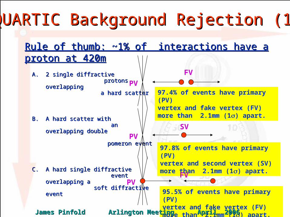
QUARTIC Background Rejection (1)QUARTIC Background Rejection (1)
A.A. 2 single diffractive 2 single diffractive protons overlapping protons overlapping a hard scatter a hard scatter
B.B. A hard scatter with A hard scatter with an overlapping double an overlapping double pomeron event pomeron event
C.C. A hard single diffractive A hard single diffractive event overlapping a event overlapping a soft diffractive soft diffractive eventevent
Rule of thumb: ~1% of interactions have a proton at 420mRule of thumb: ~1% of interactions have a proton at 420m
97.4% of events have primary (PV) vertex and fake vertex (FV) more than 2.1mm (1) apart.
PV
FV
97.8% of events have primary (PV) vertex and second vertex (SV) more than 2.1mm (1) apart.
95.5% of events have primary (PV) vertex and fake vertex (FV) more than 2.1mm (1) apart.
PV
PV
SV
FV
James Pinfold Arlington Meeting April 2006James Pinfold Arlington Meeting April 2006

Background Rejection (2) Background Rejection (2)
A.A. Two single diffractive protons overlapping a hard scatterTwo single diffractive protons overlapping a hard scatterB.B. A hard scatter with an overlapping double pomeron eventA hard scatter with an overlapping double pomeron eventC.C. A hard single diffractive event overlapping a soft diffractive A hard single diffractive event overlapping a soft diffractive
eventevent
Background rejection
James Pinfold Arlington Meeting April 2006James Pinfold Arlington Meeting April 2006

Achieved – a 10ps Timing Resolution Achieved – a 10ps Timing Resolution
The problem is we cannot put a PMT in a 7 TeV beam.
James Pinfold Manchester Meeting December 2005James Pinfold Manchester Meeting December 2005

Frontend Readout With the HPTDCFrontend Readout With the HPTDC• High precision Alberta-GlueX CFD Aiming for 20-ps resolution.High precision Alberta-GlueX CFD Aiming for 20-ps resolution.
• Using CERN HP-TDC as key componentUsing CERN HP-TDC as key component
• Initially we are assuming we have enough pe’s so an ampplifier Initially we are assuming we have enough pe’s so an ampplifier is not required is not required
• Technical specification of HP-TDCTechnical specification of HP-TDC– 32 32 channels/chip channels/chip 。 。 SizeSize ~~ 2.7×2.7 cm2.7×2.7 cm22 。。– External clockExternal clock :: 40MHz40MHz 。。 Synchronized to bunches.Synchronized to bunches.
– Internal clock: Internal clock: 40MHz / 160 MHz / 320 MHz internal40MHz / 160 MHz / 320 MHz internal
– Time Bin Size:Time Bin Size:• 781 ps low resolution mode + 195 ps medium resolution mode781 ps low resolution mode + 195 ps medium resolution mode
• 98ps high resolution mode98ps high resolution mode
• 24 ps very high resolution mode (8 channels)24 ps very high resolution mode (8 channels)
– Time resolution: Typical valuesTime resolution: Typical values• 0.34 bin RMS (265 ps) low resolution mode + 0.44 bin RMS (86ps) medium 0.34 bin RMS (265 ps) low resolution mode + 0.44 bin RMS (86ps) medium
resolution moderesolution mode
• 0.65 bin RMS (64ps) high resolution mode0.65 bin RMS (64ps) high resolution mode
• 2.4 bin RMS (58ps) very high resolution mode2.4 bin RMS (58ps) very high resolution mode
• 0.72 bin RMS (17 ps) very high resolution mode (8 channels)0.72 bin RMS (17 ps) very high resolution mode (8 channels)
James Pinfold Arlington Meeting April 2006James Pinfold Arlington Meeting April 2006

HP-TDC Tech. Specs (continued)
• Crosstalk caused by logic core running at 40MHz. This can be corrected for using a simple table correction in the following data processing
• Variation with temperature: Maximum 100ps change with 10 Deg. change of IC temperature.
• Cross talk: Maximum 150 ps from concurrent 31 channels to one channel.
• Dynamic range: – 12 + 5 = 17 bit low resolution mode– 12 + 7 = 19 bit medium resolution mode– 12 + 8 = 20 bit (19) high resolution mode– 12 + 8 + 2 = 22 bit (21) very high resolution mode.
• Double pulse resolution: Typical 5 ns. Guaranteed 10ns• Max. recommended Hit rate: Core logic at 40 MHz
– 2 MHz per channel, all 32 channels used– 4 MHz per channel, 16 channels used.– 2 MHz per channel in very high resolution mode

Readout Electronics (1Readout Electronics (1stst take) take)
James Pinfold Arlington Meeting April 2006James Pinfold Arlington Meeting April 2006
Discrimination Shaping HPTDC
AMPLIFIER?

First Meeting on HPTDCFirst Meeting on HPTDC
• Krzysztof Piotrzkowski and I met withKrzysztof Piotrzkowski and I met with the designer of the the designer of the HPTDC chip - Alessandro Marchioro - in February 2006. HPTDC chip - Alessandro Marchioro - in February 2006.
• He expressed the opinion that we (using the HPTDC) we He expressed the opinion that we (using the HPTDC) we should be able to get down to 20 ps with some work, 15ps with should be able to get down to 20 ps with some work, 15ps with a lot more work, but he thought 10 ps would be extremely a lot more work, but he thought 10 ps would be extremely “challenging”“challenging”
• We also discussed the problem of the time jitter on the LHC We also discussed the problem of the time jitter on the LHC bunch crossing time (T0). He told us about the QPLL chip- bunch crossing time (T0). He told us about the QPLL chip- containing a Quartz crystal based Phase-Locked Loop. Its containing a Quartz crystal based Phase-Locked Loop. Its function is to act as a jitter-filter for clock signals operating at function is to act as a jitter-filter for clock signals operating at the LHC clock frequency.the LHC clock frequency.
• He also stressed the need for fibre optic transmission of signals He also stressed the need for fibre optic transmission of signals to FP420/QUARTICto FP420/QUARTIC
• Alessandro expressed a willingness to work with us to update Alessandro expressed a willingness to work with us to update his chip based on new and interesting user requirementshis chip based on new and interesting user requirements
• Last but not least we walked away with 6 sample HPTDC Last but not least we walked away with 6 sample HPTDC chips!chips!
James Pinfold Arlington Meeting April 2006James Pinfold Arlington Meeting April 2006
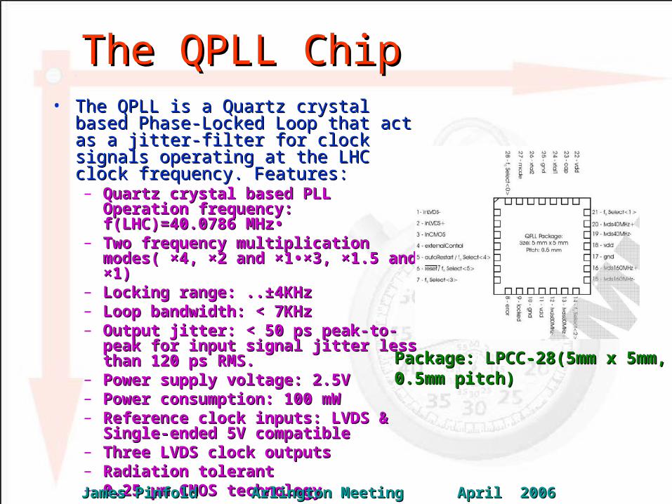
The QPLL ChipThe QPLL Chip• The QPLL is a Quartz crystal based The QPLL is a Quartz crystal based
Phase-Locked Loop that act as a jitter-Phase-Locked Loop that act as a jitter-filter for clock signals operating at the filter for clock signals operating at the LHC clock frequency. Features:LHC clock frequency. Features:– Quartz crystal based PLL Operation Quartz crystal based PLL Operation
frequency: f(LHC)=40.0786 MHz•frequency: f(LHC)=40.0786 MHz•– Two frequency multiplication Two frequency multiplication
modes( ×4, ×2 and ×1•×3, ×1.5 and ×1)modes( ×4, ×2 and ×1•×3, ×1.5 and ×1)– Locking range: ..±4KHzLocking range: ..±4KHz– Loop bandwidth: < 7KHzLoop bandwidth: < 7KHz– Output jitter: < 50 ps peak-to-peak for Output jitter: < 50 ps peak-to-peak for
input signal jitter less than 120 ps input signal jitter less than 120 ps RMS.RMS.
– Power supply voltage: 2.5VPower supply voltage: 2.5V– Power consumption: 100 mWPower consumption: 100 mW– Reference clock inputs: LVDS & Reference clock inputs: LVDS &
Single-ended 5V compatibleSingle-ended 5V compatible– Three LVDS clock outputsThree LVDS clock outputs– Radiation tolerantRadiation tolerant– 0.25 µm CMOS technology0.25 µm CMOS technology
Package: LPCC-28(5mm x 5mm, Package: LPCC-28(5mm x 5mm, 0.5mm pitch)0.5mm pitch)
James Pinfold Arlington Meeting April 2006James Pinfold Arlington Meeting April 2006
One Approach to sub-20ps TimingOne Approach to sub-20ps Timing
• One can tackle by developing the relevant technology to get One can tackle by developing the relevant technology to get down to ~10ps down to ~10ps t resolution – which won’t be easy.t resolution – which won’t be easy.
• Another approach that might work is to make a number of Another approach that might work is to make a number of independent measurements with resolutions of ~20 ps and independent measurements with resolutions of ~20 ps and average themaverage them
• This should be possible with the rather compact QUARTIC This should be possible with the rather compact QUARTIC approach.approach.
• This approach would require us to eliminate important sources This approach would require us to eliminate important sources of coherent noise – “or correlated influence” on the of coherent noise – “or correlated influence” on the independent measurements.independent measurements.
• If this can be done it would seem to be the easiest approach to If this can be done it would seem to be the easiest approach to sub-20ps timing resolution.sub-20ps timing resolution.
Future WorkFuture Work• Ascertain whether or not we can use signal direct from MCPMTAscertain whether or not we can use signal direct from MCPMT• If not identify a suitable amplifier If not identify a suitable amplifier • Construct a prototype readout boardConstruct a prototype readout board• Construct a test setup capable of measuring time resolutions Construct a test setup capable of measuring time resolutions
down to the ~20 ps level down to the ~20 ps level • Test the readout board and iterateTest the readout board and iterate• PROBLEMS:PROBLEMS:
– The Centre for Subatomic Research has recently moved to a The Centre for Subatomic Research has recently moved to a “decant” building – to await a new building“decant” building – to await a new building
– We lost 2-3 months packing up to move and we will likely be We lost 2-3 months packing up to move and we will likely be much less efficient during the unpacking phase (1-2 months)much less efficient during the unpacking phase (1-2 months)
• However, we should be able to finalize the design of the first However, we should be able to finalize the design of the first prototype board based on the HPTDC in the next few weeksprototype board based on the HPTDC in the next few weeks
• The board layout will take around a month with board delivery The board layout will take around a month with board delivery another two weeks.another two weeks.
• Thus we could have the first FE readout boards by as early as the Thus we could have the first FE readout boards by as early as the end of June 06.end of June 06.

EXTRA SLIDES

Initial Geometry for QUARTICInitial Geometry for QUARTIC
MCP-PMTMCP-PMT
proton
oCerenk Cerenk
oi i
For quartz n(λ)~1.54
1 1cos(θ )= = = 0.65; θ =49.5
βn n
1For TIR sin(θ ) = = 0.65; θ = 40.5
n
Cerenkov Photons
James Pinfold Manchester Meeting December 2005James Pinfold Manchester Meeting December 2005
20 fused silica bars 6mm20 fused silica bars 6mm22 x 100 mm x 100 mm NB fused silica is rad-hard NB fused silica is rad-hard

What is aWhat is a MCP-PMT?MCP-PMT?
Burle 2” MCP-PMT
The MCP-PMT is a micro channel plate equipped with a The MCP-PMT is a micro channel plate equipped with a photocathode & (usually) a multi-anode readoutphotocathode & (usually) a multi-anode readout

Geant4 SimulationGeant4 Simulation
• The detector simulation includes:The detector simulation includes:–Tracking and timing of Cerenkov photons to the MCP-PMT Tracking and timing of Cerenkov photons to the MCP-PMT
–Wavelength dependent refractive index, attenuation & reflectivity Wavelength dependent refractive index, attenuation & reflectivity
–Ability to study cladding (eg air) or a reflective layer (with a Ability to study cladding (eg air) or a reflective layer (with a possibility of including diffuse reflection)possibility of including diffuse reflection)
–The effects of coupling grease (if necessary)The effects of coupling grease (if necessary)
Al reflection (Cladding with NA=0.37)
James Pinfold Manchester Meeting December 2005James Pinfold Manchester Meeting December 2005

Simulating the MCP-PMTSimulating the MCP-PMT
• Arrival time at the face of the MCP-PMT recordedArrival time at the face of the MCP-PMT recorded
• Simulate geometrical acceptance Simulate geometrical acceptance
• Implement wavelength dependence of the photo-cathode QE.Implement wavelength dependence of the photo-cathode QE.
• Simulate PMT transit-time jitter by adding a normally distributed Simulate PMT transit-time jitter by adding a normally distributed random time jitter with the appropriate standard deviationrandom time jitter with the appropriate standard deviation
• Simulate the layout of the anode pad readout of the MCP-PMT.Simulate the layout of the anode pad readout of the MCP-PMT.
• Assume that when the MCP-PMT o/p voltage reaches a certain Assume that when the MCP-PMT o/p voltage reaches a certain level it triggers the discriminator – this level corresponds to a level it triggers the discriminator – this level corresponds to a certain number of photons having arrived.certain number of photons having arrived.
James Pinfold Manchester Meeting December 2005James Pinfold Manchester Meeting December 2005

Cerenkov Light in Fused Silica*Cerenkov Light in Fused Silica*
*UTA simulation
λ #PH QE #PH*Q E Θc n
180-250 1652.6 15.70% 259.5 49.6 1.544
250-350 1148.7 18.00% 206.8 47.8 1.490
350-450 624.7 19.90% 124.3 47.2 1.471
450-550 394.3 11% 43.4 46.9 1.464
550-650 271.1 1.50% 4.1 46.7 1.458
total 4100 638.0
22 2
1
# . 2 sin( ) 1/ ph L c d
UV is important! 640 total pe’s : ~130 pe’s/6mm rod (collection efficiency reduces this number to ~80 pe’s/bar)
James Pinfold Manchester Meeting December 2005James Pinfold Manchester Meeting December 2005

Photon Arrival Times (1)Photon Arrival Times (1)
red = totally internally reflected lightgreen = extra light if aluminized
PicosecondsPicoseconds
QE not included
First 10ps 22 photonsFirst 10ps 22 photonsFirst 20ps 51 photonsFirst 20ps 51 photonsFirst 30ps 80 photonsFirst 30ps 80 photonsFirst 40 ps 107 photonsFirst 40 ps 107 photons
Half maximum rise time ~3psHalf maximum rise time ~3ps
Nu
mb
er o
f p
ho
ton
s
James Pinfold Manchester Meeting December 2005James Pinfold Manchester Meeting December 2005

Photon Arrival Times (2)Photon Arrival Times (2)
red = totally internally reflected lightgreen = extra light if aluminized
QE included
First 10ps 3 pe’sFirst 10ps 3 pe’sFirst 20ps 8 pe’sFirst 20ps 8 pe’sFirst 30ps 12 pe’sFirst 30ps 12 pe’sFirst 40ps 16 pe’sFirst 40ps 16 pe’s
Half maximum rise time ~3psHalf maximum rise time ~3ps
PicosecondsPicoseconds
Nu
mb
er o
f p
ho
toel
ectr
on
sN
um
ber
of
ph
oto
elec
tro
ns
James Pinfold Manchester Meeting December 2005James Pinfold Manchester Meeting December 2005
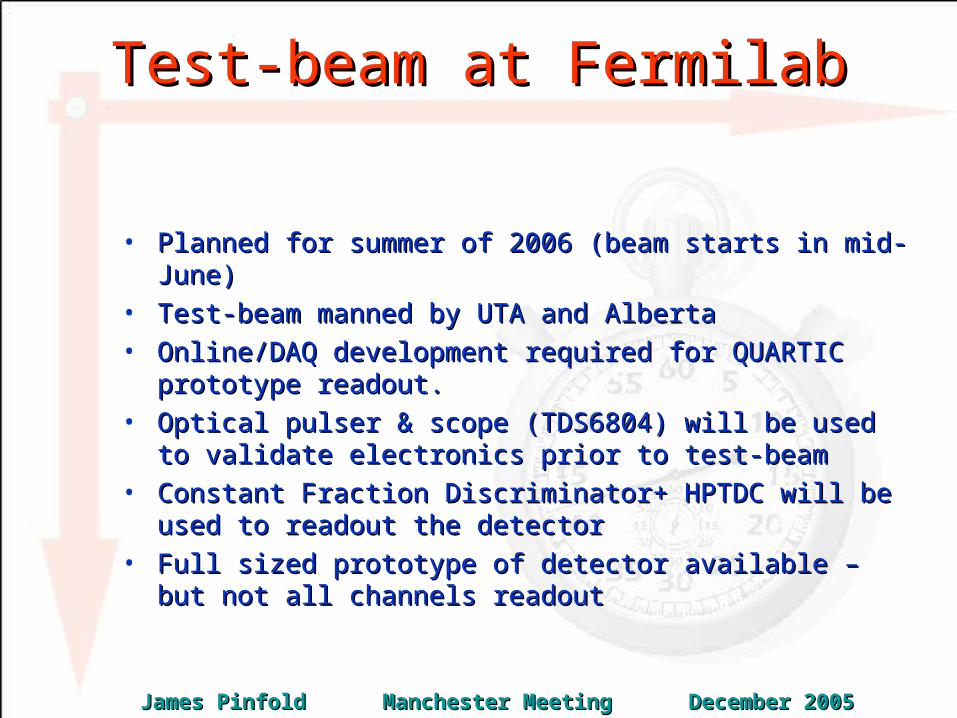
Test-beam at FermilabTest-beam at Fermilab
• Planned for summer of 2006 (beam starts in mid-June)Planned for summer of 2006 (beam starts in mid-June)• Test-beam manned by UTA and AlbertaTest-beam manned by UTA and Alberta• Online/DAQ development required for QUARTIC prototype Online/DAQ development required for QUARTIC prototype
readout.readout.• Optical pulser & scope (TDS6804) will be used to validate Optical pulser & scope (TDS6804) will be used to validate
electronics prior to test-beamelectronics prior to test-beam• Constant Fraction Discriminator+ HPTDC will be used to Constant Fraction Discriminator+ HPTDC will be used to
readout the detectorreadout the detector• Full sized prototype of detector available – but not all channels Full sized prototype of detector available – but not all channels
readoutreadout
James Pinfold Manchester Meeting December 2005James Pinfold Manchester Meeting December 2005

Funding InitiativesFunding Initiatives
UTA (with UofA collaboration):UTA (with UofA collaboration):Texas ARP $100K/2 years, TOF and Mechanics; Texas ARP $100K/2 years, TOF and Mechanics; passed University pre-proposal stagepassed University pre-proposal stage(12/79); proposal due Feb. 14, award May 15(12/79); proposal due Feb. 14, award May 15
DOE ADR $130k/2 years, TOF only, proposal dueDOE ADR $130k/2 years, TOF only, proposal dueDec. 15! Award date June. Burle is contributing Dec. 15! Award date June. Burle is contributing MCP-PMT’s 25MCP-PMT’s 25m pore (60 psec TTS), 10m pore (60 psec TTS), 10m porem pore(~30 psec expected), 10um, dropped face plate(~30 psec expected), 10um, dropped face plate(removes tail from recoil electrons), and high current (removes tail from recoil electrons), and high current capability versioncapability version
AlbertaAlbertaA small amount of initial funding is available (~$15K) A small amount of initial funding is available (~$15K) plus electronics engineer time (at $5/hr!)plus electronics engineer time (at $5/hr!)
James Pinfold Manchester Meeting December 2005James Pinfold Manchester Meeting December 2005
ConclusionConclusion
• The QUARTIC precision ToF detector offers the possibility of The QUARTIC precision ToF detector offers the possibility of reducing physics backgrounds to exclusive central Higgs reducing physics backgrounds to exclusive central Higgs production at ATLAS production at ATLAS
• ToF detector resolutions of ~10ps have been achieved ToF detector resolutions of ~10ps have been achieved previously and initial simulation studies indicate that we should previously and initial simulation studies indicate that we should be able to deploy a detector with resolution of better than 30ps be able to deploy a detector with resolution of better than 30ps at the LHCat the LHC
• This resolution will allow us to reduce the background from This resolution will allow us to reduce the background from events contributing central “activity” and two protons at 420m events contributing central “activity” and two protons at 420m (hard scatters + diffractive & double pomeron events) by more (hard scatters + diffractive & double pomeron events) by more than 90%.than 90%.
• The R&D effort to develop QUARTIC is well underway with the The R&D effort to develop QUARTIC is well underway with the first beam-test to take place in the summer of 2006.first beam-test to take place in the summer of 2006.
James Pinfold Manchester Meeting December 2005James Pinfold Manchester Meeting December 2005

n=1 n>>1
Cerenkov EffectCerenkov Effect
Use this property of prompt radiation to develop a fast timing counterUse this property of prompt radiation to develop a fast timing counter
particle
James Pinfold Manchester Meeting December 2005James Pinfold Manchester Meeting December 2005