Quantum Erasing - DiVA portalkth.diva-portal.org/smash/get/diva2:719811/FULLTEXT01.pdf · Quantum...
14
Transcript of Quantum Erasing - DiVA portalkth.diva-portal.org/smash/get/diva2:719811/FULLTEXT01.pdf · Quantum...

Quantum Erasing
Filip Backman, 910516-5550
Philip Sundqvist, 920817-1737
Supervisors: Marcin Swillo, Gunnar Björk
Institution: Applied Physics
May 21, 2014
1

Contents
1 Introduction 5
2 Theory 5
2.1 Interference . . . . . . . . . . . . . . . . . . . . . . . . . . . . 5
2.2 Wave-particle duality . . . . . . . . . . . . . . . . . . . . . . . 5
2.3 Distinguishability . . . . . . . . . . . . . . . . . . . . . . . . . 6
2.4 Polarisation . . . . . . . . . . . . . . . . . . . . . . . . . . . . 6
3 Method 7
4 Our demonstration 8
5 Construction 11
6 Discussion 12
7 Instructions 13
8 Acknowledgements 14
2

Abstract
Quantum Physics has many concepts that are hard to conceive. Themain goal with this project is to explain and demonstrate some of these.
To achieve this, a setup has been built where a beam is split intotwo paths, which then subsequently coincide on a mutual screen.
If we choose to deny ourselves the possibility of determining whichpath the wave takes, the paths are said to be indistinguishable. Inthis case the waves from the two di�erent paths will interfere, whichwill be seen as a periodic interference pattern on the screen. If weinstead choose to do a measurement in such a way that we know whichpath the wave took, the paths are distinguishable. As this occurs, theinterference pattern will disappear. There is also a third possibility.The third possibility is to leave the opportunity of measuring, but notactually doing it. This alternative gives the same result as if the pathwas actually determined, the interference pattern will disappear.
In this setup the wavefront is split into two by a thin metal wire.On each side is a polarisation �lter with perpendicular polarisationwith respect to one another. These �lters help us to distinguish thetwo possible paths. By placing a third polariser between the wire andthe screen, parallel to one of the earlier polarisers, it can be seen whichpath the light has taken, making the paths distinguishable.
If the third polariser is instead rotated at a 45o-angle letting throughequal parts of both paths, the passing light will have a mutual directionof polarisation. This will once again make the light indistinguishableand the interference pattern will reappear.
Sammanfattning
Kvantfysiken har många svårbegripliga koncept. Målet med detta pro-jekt är att förklara och demonstrera vissa av dessa.
För att uppnå detta har en uppställning byggts där en ljusstråle delasupp och får utbredas längs två olika vägar. Vägen kan kodas på de re-spektive vägarna med hjälp av polarisations�lter. Därefter låter manljuset som tog de två vägarna sammanfalla på en gemensam skärm.
Om vi väljer att avsäga oss möjligheten att avgöra vilken väg ljusettar, sägs ljuset som tog respektive väg icke-särskiljbart. I detta fallkommer vågorna från de två olika banorna interferera, vilket syns somett mönster på skärmen. Däremot om vi väljer att mäta vilken banavågen tar är banorna särskiljbara. När vi gör detta val försvinner inter-ferensmönstret. Det �nns även ett tredje alternativ. Det alternativetär att skapa en möjlighet att mäta, men inte utnyttja den. Detta fallger samma resultat som att faktiskt mäta, det vill säga interferens-
3

mönstret försvinner.
I vår uppställning delas vågfronten upp i två delar med hjälp av en met-alltråd. På vardera sida om tråden sitter polariserings�lter med vinkel-räta polarisationsriktningar i förhållande till varandra. Med hjälp avdessa kan vägarna särskiljas. Genom att sätta ett tredje polarisations-�lter mellan metalltråden och skärmen parallellt med ett av �ltren kanman bestämma vilken väg ljuset tagit, vilket gör banorna särskiljbara.
Om vi däremot sätter det tredje �ltret i 45o-vinkel mot de vinkelrätapolarisatorerna så att ljuset från de båda vägarna återigen får sammapolarisationsrikting, går det inte längre att avgöra vilken väg ljusettagit. Alltså är vägarna nu icke-särskiljbara och interferensmönstretpå skärmen återuppstår.
4

1 Introduction
There are many well-known concepts within quantum physics that arecounter-intuitive and di�cult to understand. One of these is distin-guishability and how it a�ects interference of waves or particles. Thepurpose of this project is to show and explain this phenomenon in aneducational way by building an experimental setup. By using waves,which have a wave function similar to the probability amplitude func-tion of a quantum particle, we can show how distinguishability a�ectsthe propensity of quantum particles to interfere.
The report begins with some background theory explaining interfer-ence, wave-particle duality, distinguishability and polarisation. It thencontinues on with an explanation of the setup, followed by an instruc-tion of how to show and explain it to an audience. It then ends withan explanation of how the setup was built and a discussion.
2 Theory
2.1 Interference
Interference is the phenomenon which occurs when two waves interactcausing their superposition to have areas where the resulting wavefunc-tion is increased or decreased. If a light source illuminates a screen withtwo slits, the two wave-fronts may have the same frequency and phase.For every point, two interfering waves with amplitudes A1 and A2, andwith phases ei∗φ1∗r1 and ei∗φ2∗r2 can be added together as:
A1 ∗ ei∗φ1∗r1 +A2 ∗ ei∗φ2∗r2
What we actually see with our eyes is the intensity, which is the ab-solute square of the amplitude. This is important since it gives thedi�erence between interfering waves and non-interfering waves. For in-terfering waves they are added as above, but for non-interfering wavesthe intensity for each wave is computed individually and then addedto get the resulting intensity.[2]
2.2 Wave-particle duality
The wave-particle duality is a fundamental concept in quantum physics.It was discovered by Louis de Broglie in 1924, when he postulated thatall matter has wavelike behaviour. The wavelength of a particle isdetermined by the equation:
λ =h
p
In the same way, light can be viewed as both particles and waves. [1]The momentum of a photon is:
p = ~k =h
2π
2π
λ=h
λ
5

2.3 Distinguishability
Distinguishability is a concept that is best described by the famousdouble-slit experiment, in which a source emits particles towards ascreen with two small slits. In a �particle picture�, the particles wouldfollow straight lines through the slits and produce two lines shaped likethe slits when observed by a detector.
The wave-particle duality however, states that each particle can alsobe described as a wave. The particles can then di�ract and thus in-teract after passing through the slits, causing an interference patternon the screen. However, each particle would also be able to travelthrough both slits at the same time as a superposition of both choicesof path. Thus one does not need a stream of particles to create the in-terference pattern. Instead, the particles could be sent one by one andthe particle would interfere with itself, causing the interference patternto emerge. The two paths that the particle can follow are said to beindistinguishable when the particle follow both as a superposition ofstates.[1]
By measuring through which slit the particle is travelling through,the superposition of states collapses to one or the other of the twopossibilities. Therefore, the particle will only travel through one of theslits and the interference pattern disappears.
A third option is to not measure which slit the particle is passingthrough, but still leave the opportunity to do so by "marking" it. Thiswill give the same result as actually performing the measurement. Thereason is that the option to measure the path of the particle makes thetwo paths distinguishable, which causes the wave function to collapseinto one of the states. [1]
2.4 Polarisation
Light consists of electric �elds and magnetic �elds, where, in the so-called far �eld, the magnetic �eld and the electric �eld are perpendicu-lar to each other and the direction of propagation. A linearly polarisedwave has a �x direction along which the electric �eld is alternating,called the polarisation of the wave. [3]
Polarisers are �lters that allows light of a certain polarisation to passthrough while blocking light with other polarisations. Every polarisa-tion direction can be described as a superposition of two perpendiculardirections. This means that if a wave has an angle to the polarisation�lter, it will lose intensity but still be able to pass through to somedegree. The intensity of the wave after passing through the �lter is:
I = I0 cos2(θ)
Here I0 is the intensity of the incoming wave and θ is the angle betweenthe polarisation of the incoming beam and the polariser. [2]
6

3 Method
Figure 1: Drawn picture of the setup
The experimental setup was created with the intention of showing twomajor scenarios. We wished to be able to alternate between showing asimple di�raction with indistinguishable waves on either side, as wellas a quantum eraser with a delayed choice.
The most important part of the setup is the object which is supposedto split the beam and be able to distinguish the waves depending onwhich side it goes on. This was created by using two polarising �lterswith perpendicular direction of polarisation placed as closely as possi-ble together and then adding a 0.1 mm thick metal wire in the smallgap that is inevitably going to appear between the �lters. The thick-ness of the wire was determined through trial and error. A smallerwire did not cover the entire gap between the �lters and a thicker wireresulted in an interference pattern that was too dense. By splitting thelight beam with the wire and having di�erent polarisations on eitherside of it the path which the light beam travels will be distinguishable.Behind this object an analyzer, which consists of a polariser that canbe rotated, is placed. This polariser can then either measure on whichside the beam has passed by, or nullify the earlier distinguishabilityon the light passing through it by rotating all the light to the samepolarisation.
7
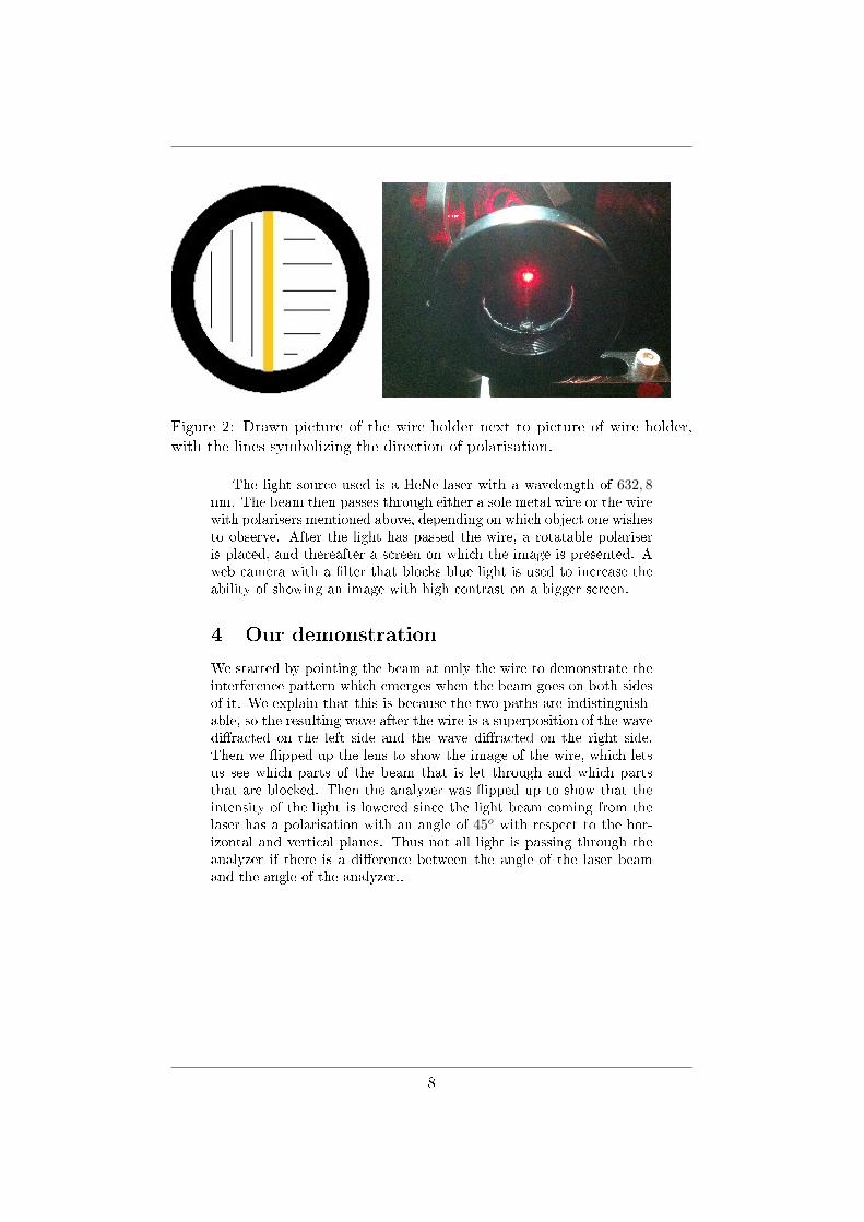
Figure 2: Drawn picture of the wire holder next to picture of wire holder,
with the lines symbolizing the direction of polarisation.
The light source used is a HeNe-laser with a wavelength of 632, 8nm. The beam then passes through either a sole metal wire or the wirewith polarisers mentioned above, depending on which object one wishesto observe. After the light has passed the wire, a rotatable polariseris placed, and thereafter a screen on which the image is presented. Aweb camera with a �lter that blocks blue light is used to increase theability of showing an image with high contrast on a bigger screen.
4 Our demonstration
We started by pointing the beam at only the wire to demonstrate theinterference pattern which emerges when the beam goes on both sidesof it. We explain that this is because the two paths are indistinguish-able, so the resulting wave after the wire is a superposition of the wavedi�racted on the left side and the wave di�racted on the right side.Then we �ipped up the lens to show the image of the wire, which letsus see which parts of the beam that is let through and which partsthat are blocked. Then the analyzer was �ipped up to show that theintensity of the light is lowered since the light beam coming from thelaser has a polarisation with an angle of 45o with respect to the hor-izontal and vertical planes. Thus not all light is passing through theanalyzer if there is a di�erence between the angle of the laser beamand the angle of the analyzer..
8

Figure 3: To the left is a graph of the intensity of light when the paths are
indistinguishable. To the right is a picture of our di�raction pattern when
hitting only wire.
We then �ipped down all components and �ipped up the wire holderto demonstrate there will be di�raction but no interference pattern,since the paths are distinguishable. We explained that this is becausethe polarisers on each side are rotated 90o with respect to each other,so the light passing through each side is �marked�. It is important tonote that the paths not necessarily have to be measured for the eraserto work. Instead they only have to be distinguishable in principle, justas in this setup.
Figure 4: To the left is a graph over the intensity of light, when the paths are
distinguishable. To the right is a picture of our pattern with distinguishable
paths.
The analyzer was �ipped up so that the polarisation was in verticaldirection so that the light only passed through one side. This lessenedthe intensity as well as showing only one half of the original picture.We �ipped up the lens to show the audience that the beam actuallyonly travels through one side of the wire. We explained that this is the
9

reason that the paths in the previous setup was distinguishable. Simplyby adding a polariser, the light from each side can easily be separated.The analyzer was rotated 90o to demonstrate on both sides.
Figure 5: To the left is a graph over light intensity when the light only takes
the right path. To the right is a picture of the result of a half plane.
We rotated the analyzer 45o to make the paths indistinguishableonce again. Since the analyzer aligns the two di�erent polarisationsof all incoming light; the polarisation is independent of which side ofthe wire it travelled through, and we cannot use a third polariser todetermine which way the light has travelled. Thus, once again thepaths are made indistinguishable. Important to note is that the pathsare distinguishable for a little while, in the region between the �rst andsecond polariser. This can be shown by once again �ipping down thesecond polariser and note that the region of distinguishability betweenthe �rst and second polariser now has been extended all the way tothe screen.
Figure 6: The red line is the intensity of indistinguishable paths, and the blue
for distinguishable paths. The right is a picture of erased distinguishability.
10

5 Construction
We started with constructing the analyzer. Philip cut a circle out ofthe polarising �lter with a small �at edge on one side, to easily deter-mine the polarisation orientation of the circle. Then he mounted it ona rotatable holder.
To build the wire holder Philip cut out two half circles from the polar-ising �lter with perpendicular polarisation with respect to each other.The polarisers were cut out using scissors. We tried with razor bladesand utility knives as well, but the �lter was too thick for us to getthrough in one cut. Therefore the results with scissors were the best.The wire holder polarisers were done by using the factory cut edges ofthe polarisation �lter. We made this decision because when we triedto cut our own edges from circles we had cut out of the big �lter, wegot less smooth edges and also the �lters got squeezed together by thescissors and became thinner. The �at sides of the two halves were thenpolished by Philip. Filip then glued these two onto a thin metal ring,which �t to the holder, and also put a thin metal wire in the small gapbetween the two halves. The glue used was a marine epoxy to makesure sure the wire stays in place. By using a microscope, the wire wasadjusted to �t the miniscule gap between the two halves perfectly andnot allowing any light to pass through. Filip also built a wire holderwithout polarising �lter, by gluing a metal wire to a holder-ring. Philipthen mounted the two objects onto a �ippable stand that switches be-tween the two of them easily and with high precision.
Two lenses are used in the setup. One was placed by Filip betweenthe mirrors to make the beam a little broader before hitting the wire,so that it was easier to hit the wire and get through light on both sides.We tested a few lenses and chose a lens with a small magni�cation, aswe still wanted the beam to stay focused in a small area. The secondlens was placed by Philip as in Figure 1. It was chosen for its greatmagni�cation, also through trial and error. This lens had to magnifythe image a lot, since we wanted to be able to show the thickness ofthe wire and on which side of the wire the light was passing throughon the screen.
A screen and camera was necessary to get a good picture of the image.This screen was made out of a hard plastic board that Filip drilleda hole through and attached to a �ippable mount with a screw. Onthe visible side of the screen, Philip taped a white piece of paper withadhesive tape.
The laser, the screen and the two mirrors were mounted onto a bread-board by Filip, while Philip mounted the wire-holder, the lens and theanalyzer.
The laser beam and the wire holder were then adjusted to hit the
11

wire on a good spot (since it was a bit uneven), as well as hitting thesecondary wire holder, when �ipped.
Philip also mounted a camera directed at the screen, to make it possibleto show the experiment on a bigger screen.
6 Discussion
Using more accurate cutting techniques when cutting the polariserswould have given a better result, since we do not know whether thepolariser board was of even thickness throughout. If we could have cutperfect edges ourselves, we would have made two halves from withinthe same dm2. Having a stronger laser as well as a �lter for our ex-act wavelength would have made our image clearer, since the intensitywould have become larger in comparison to the ambient light.
This experiment can in theory also be made with electrons and shoot-ing one particle at the time on the object. Collecting enough datato get a good interference pattern demands much time however, andwould not be suitable to demonstrate in real-time during a presentationor lecture. Furthermore, the wire would have to be much thinner tocompensate for the much shorter wavelength. This can be explained bylooking at the interference pattern from a single-slit experiment. Thecondition for the maximum intensity peaks are sin(θ) = m·λ
d . Thus,the lower wavelength of the electron will result in a much denser inter-ference pattern, which can not be seen. To make it sparser, d has to bedecreased. A 1eV photon has a wavelength of 1240nm and an electronwith a kinetic energy of 1eV has a wavelength of 1.23nm. Therefore,the thickness of the wire for an experiment with electrons would haveto be ca 1000 times thinner than our wire, which is very di�cult toachieve.
The laser used in this experimental setup is a HeNe-laser with a poweroutput of 15mW, which is quite weak. This makes the image it createsrather weak, and it cannot be seen in a lit up room. Therefore thesetup must be completely shielded from ambient light for the camerato be able to get a clear picture of the di�raction. This means thatthere is a pretty low possibility of projecting the pattern directly ona wall, which would be good for demonstrations as it would not onlymake the di�raction pattern clearer, but also not require a computerand a projector. The downsides of having a more powerful laser isthat there may be some scattered light that may pose danger to theaudience, which is an unnecessary risk to take.
12

7 Instructions
Figure 7: Drawn picture of the setup
Flip wire holder to show only wire.Flip up lens.Flip wire holder.Flip up analyzer.Rotate analyzer.Flip down analyzer.Flip down lens.Flip up analyzer at 45o.
13

8 Acknowledgements
We would like to thank our supervisors: Researcher Marcin Swillo andProfessor Gunnar Björk, who have helped us with our project.
References
[1] McIntyre, Manogue Tate, Quantum Mechanics: Pearson New In-
ternational Edition. Pearson Education, First edition, 2013.
[2] Young Freedman, Sears and Zemansky's University Physics with
Modern Physics: International Edition, Pearson Education, Thir-teenth edition, 2012.
[3] David J. Gri�ths, Introduction to Electrodynamics: International
Edition. Pearson Education, Third edition, 1998.
14