Quantification of GR effects in muon g-2, EDM and … · E-mail: [email protected]...
31
arXiv:1803.01395v4 [gr-qc] 26 Jul 2018 Quantification of GR effects in muon g-2, EDM and other spin precession experiments András László Wigner Research Centre for Physics, Budapest E-mail: [email protected] Zoltán Zimborás Wigner Research Centre for Physics, Budapest E-mail: [email protected] Abstract. Recently, Morishima, Futamase and Shimizu published a series of manuscripts, putting forward arguments, based on a post-Newtonian approximative calculation, that there can be a sizable general relativistic (GR) correction in the experimental determination of the muon magnetic moment based on spin precession, i.e., in muon g-2 experiments. In response, other authors argued that the effect must be much smaller than claimed. Further authors argued that the effect exactly cancels. Also, the known formulae for de Sitter and Lense-Thirring effect do not apply due to the non-geodesic motion. All this indicates that it is difficult to estimate from first principles the influence of GR corrections in the problem of spin propagation. Therefore, in this paper we present a full general relativistic calculation in order to quantify this effect. The main methodology is the purely differential geometrical tool of Fermi-Walker transport over a Schwarzschild background. Also the Larmor precession due to the propagation in the electromagnetic field of the experimental apparatus is included. For the muon g-2 experiments the GR correction turns out to be very small, well below the present sensitivity. However, in other similar storage ring experimental settings, such as electric dipole moment (EDM) search experiments, where the so-called frozen spin method is used, GR gives a well detectable effect, and should be corrected for. All frozen spin scenarios are affected which intend to reach a sensitivity of 0.1 microradians/second for the spin precession in the vertical plane. Keywords: Thomas precession, Larmor precession, spin precession, muon g-2, anomalous magnetic moment, electric dipole moment, EDM
Transcript of Quantification of GR effects in muon g-2, EDM and … · E-mail: [email protected]...

arX
iv:1
803.
0139
5v4
[gr
-qc]
26
Jul 2
018
Quantification of GR effects in muon g-2, EDM and
other spin precession experiments
András László
Wigner Research Centre for Physics, Budapest
E-mail: [email protected]
Zoltán Zimborás
Wigner Research Centre for Physics, Budapest
E-mail: [email protected]
Abstract. Recently, Morishima, Futamase and Shimizu published a series of
manuscripts, putting forward arguments, based on a post-Newtonian approximative
calculation, that there can be a sizable general relativistic (GR) correction in the
experimental determination of the muon magnetic moment based on spin precession,
i.e., in muon g-2 experiments. In response, other authors argued that the effect must
be much smaller than claimed. Further authors argued that the effect exactly cancels.
Also, the known formulae for de Sitter and Lense-Thirring effect do not apply due
to the non-geodesic motion. All this indicates that it is difficult to estimate from
first principles the influence of GR corrections in the problem of spin propagation.
Therefore, in this paper we present a full general relativistic calculation in order to
quantify this effect. The main methodology is the purely differential geometrical tool of
Fermi-Walker transport over a Schwarzschild background. Also the Larmor precession
due to the propagation in the electromagnetic field of the experimental apparatus is
included. For the muon g-2 experiments the GR correction turns out to be very small,
well below the present sensitivity. However, in other similar storage ring experimental
settings, such as electric dipole moment (EDM) search experiments, where the so-called
frozen spin method is used, GR gives a well detectable effect, and should be corrected
for. All frozen spin scenarios are affected which intend to reach a sensitivity of 0.1
microradians/second for the spin precession in the vertical plane.
Keywords: Thomas precession, Larmor precession, spin precession, muon g-2, anomalous
magnetic moment, electric dipole moment, EDM

GR effects in muon g-2, EDM and other spin precession experiments 2
1. Introduction
In a recent series of papers [1, 2, 3], it was claimed that, in the muon anomalous magnetic
moment experiments [4, 5, 6, 7], there can be a general relativistic (GR) correction to the
precession effect of the muon spin direction vector when orbiting in the magnetic storage
ring sitting on the Earth’s surface in a Schwarzschild metric. These calculations were
based on a post-Newtonian approximation, and the authors claimed that the pertinent
effect may cause an unaccounted systematic error in the measurement of the muon’s
anomalous magnetic moment, often referred to as g-2. Other papers [8, 9] responded
that the effect is much smaller. Further papers [10] responded that the effect exactly
cancels. Moreover, the usual formulae of de Sitter and Lense-Thirring precession [11] do
not apply, since the pertinent orbit is non-geodesic. All this suggests that it is relatively
difficult to say something from first principles on the magnitude of GR corrections for
spin transport in a gyroscopic motion along a forced orbit. Motivated by these, in the
present paper, we intend to quantify the pertinent effect in the context of GR. We use
the differential geometrical tool of Fermi-Walker transport of vectors along trajectories
in spacetime. In this way, the kinematic precession, called the Thomas precession,
can be quantified over the Schwarzschild background field of the Earth. This is then
compared to the Minkowski limit, i.e., when GR is neglected. The effect of the Larmor
precession in the electromagnetic field of the experimental setting is also quantified, and
its corresponding GR correction is also evaluated. The calculations show that the GR
corrections for the actual g-2 experimental setting [4, 5, 6, 7] is very small, well below the
experimental sensitivity. There are, however, other spin precession experiments, such as
the electric dipole moment (EDM) search experiments [12, 13, 14], where it turns out
that GR gives a rather large signal. Since these experiments are intended as sensitive
probes for Beyond Standard Model (BSM) scenarios, their experimental data should be
corrected for the GR effect. In particular, the EDM experiments [12, 13, 14] could be
thought of also as sensitive GR experiments on spin propagation of elementary particles,
kind of microscopic versions of Gravity Probe B [15, 16] gyroscope experiment. During
the past years there have been a few papers warning about the possibility of such an
effect [17, 18, 19, 20, 21]. These estimations, however, are not fully covariant Lorentz
geometric GR calculations, but are mostly special relativistic or semi-general relativistic,
or applying other kind of approximations such as not fully taking into account GR
for the electrodynamic part. As a result, the estimations [17, 18, 19, 20] differ from
our geometric GR calculation in the details of the particle velocity dependence, and
with some factors. The post-Newtonian estimation of [21], where the GR effect for
the special case of a purely electric frozen spin storage ring is quantified, is confirmed
by our covariant calculations. Since the EDM signal is expected to sit on this large
GR background of the order of 30 nrad/sec, the pertinent factors matter a lot for
discrimination from a BSM signature with the planned precision of 1 nrad/sec. The
GR signal, however, can also be disentangled from a true EDM signal due to their
opposite space reflection behavior, i.e., by switching beam direction.

GR effects in muon g-2, EDM and other spin precession experiments 3
The structure of the paper is as follows. Section 2 outlines the kinematic setting
of our model of the experimental situation. In Section 3 and 4, we discuss, from
a geometrical point of view, the Fermi-Walker transport (gyroscopic equation) and
the general relativistic Thomas precession, respectively. The GR corrections to the
Thomas precession is evaluated in Section 5. In Section 6, the idealized model
of electromagnetic fields in an electromagnetic storage ring over a Schwarzschild
background is outlined, and their Fermi-Walker-Larmor spin transport is evaluated in
Section 7. The analytical formulae are derived for a combined Thomas and Larmor
precession over the Schwarzschild background in Section 8. Finally, in Section 9 the
total GR corrections are evaluated, which is followed by our concluding remarks in
Section 10.
2. The kinematic setting
The kinematic setting of the experiment is outlined in Fig. 1. The gravitational field
of the Earth is modelled by a Schwarzschild metric with rS being the corresponding
Schwarzschild radius, rS = 2MGc2
. The non-sphericity of the Earth as well as its rotation
is neglected. We use the standard Schwarzschild coordinates t, r, ϑ, ϕ, and thus the
components of the Schwarzschild metric read as:
gab(t, r, ϑ, ϕ) =
1− rSr
0 0 0
0 − 11− rS
r
0 0
0 0 −r2 0
0 0 0 −r2 sin2 ϑ
. (1)
In such coordinates, the Earth’s surface is at an r = const level-surface, we denote this
radius by R. By convention, the North pole of the spherical coordinates is adjusted such
that it corresponds to the central axis of the storage ring, i.e., this axis is at ϑ = 0. The
entire storage ring is located at an r = R, ϑ = const surface, where the corresponding
ϑ coordinate value is denoted by Θ. The radius of the storage ring is then L = R sinΘ.
Throughout the paper, the coordinate indices are denoted by fonts like a, b, c, . . . and
take their value from the index set 0, 1, 2, 3. Occasionally, the alternative notation
t, r, ϑ, ϕ is used as equivalent symbols for the indices 0, 1, 2, 3. Moreover, we will
also use the Penrose abstract indices [23], with index symbol fonts like a, b, c, . . . in order
to aid the notation of various tensorial trace expressions in a coordinate independent
way.
The trajectory of the orbiting particle inside the storage ring on the Earth’s surface
is described by a worldline t 7→ γω(t) with coordinate components
γωa(t) =
t
R
Θ
ω√
1− rSRt mod 2π
, (2)
where for convenience the worldline is parameterized by the Killing time t and not with

GR effects in muon g-2, EDM and other spin precession experiments 4
R
Θ
L
Earth surface
storage ring
L=R sin Θ
r coordinate
t coo
rdin
ate
Schwarzschild radius
θ,φ coordinates
Domain of outer communication
worldline of beam injection point
orbi
ting
part
icle
in s
tora
ge r
ing
on E
arth
sur
face
worldline of beam injection point
initial spin direction vector
particle trajectory orbiting in the storage ring on Earth’s surface
Figure 1. The outline of the kinematic setting of the experiment. Top panel:
the particle storage ring is sitting on the Earth’s surface. The radius of the Earth
is denoted by R, the storage ring radius by L, and we set the North pole of our
spherical coordinates by convention to the center of the storage ring. Bottom left panel:
illustration of the laboratory setting in Earth’s Schwarzschild spacetime. Throughout
the paper the Schwarzschild coordinates t, r, ϑ, ϕ are used. Bottom right panel: a zoom
of the particle’s orbiting trajectory. The initial spin direction vector is Fermi-Walker
transported along the worldline of the orbiting particle in Schwarzschild spacetime.
The worldline of the beam injection point, i.e., the laboratory worldline is also shown,
along which the initial spin vector can also be Fermi-Walker transported.
its proper time. Here, ω denotes the circular frequency of the orbiting particle trajectory,
in terms of the proper time of the laboratory system. It is seen that the particles are
assumed to be orbiting on a closed circular trajectory, i.e., a beam balanced against
falling towards the Earth is assumed. This is justified by the fact that according to
[7] an electrostatic beam focusing optics is used in the g-2 experimental setup, which
is resting on the surface of the Earth, together with the storage ring. The initial spin
direction vector at t = 0 is a unit pseudolength spacelike vector, orthogonal to the curve
t 7→ γω(t). The amount of precession can be quantified via also evolving the initial
spin direction vector along the worldline of the beam injection point of the storage ring

GR effects in muon g-2, EDM and other spin precession experiments 5
(laboratory observer), described by the curve t 7→ γ0(t) having coordinate components
γ0a(t) =
t
R
Θ
0
. (3)
The worldlines t 7→ γω(t) and t 7→ γ0(t) intersect at each full revolution, i.e., at each
t = n 2π
ω√
1− rSR
, with n being any non-negative integer. In these intersection points the
propagated spin direction vectors can be eventually compared. The unit tangent vector
fields, i.e., the four velocity fields of these curves are t 7→ uωa(t) := 1
Λω(t)γω
a(t) and
t 7→ u0a(t) := 1
Λ0(t)γ0
a(t), with Λω :=√
gabγωaγωb and Λ0 :=√
gabγ0aγ0b, respectively.
In order to evaluate the spin direction vector along any point of the worldline
t 7→ γω(t) or t 7→ γ0(t), it needs to be transported along the pertinent trajectories. This
is described by the Fermi-Walker transport, i.e., by the relativistic gyroscopic transport
[22]. Let ud be a future directed unit timelike vector field, then the Fermi-Walker
derivative of a vector field wb along ud is defined as:
DFuw
b := ud∇dwb + gacw
aubud∇duc − gacw
aucud∇dub, (4)
where ∇d denotes the Levi-Civita covariant derivation associated to the metric gab. The
Fermi-Walker derivative is distinguished by the fact that DFu u
b = 0 holds, as well as the
property that for any two vector field wb and vb satisfying DFuw
b = 0 and DFu v
b = 0,
the identity ua∇a
(
gbcwbvc)
= 0 holds. In particular, whenever one has DFuw
b = 0, then
also ua∇a
(
gbcubwc)
= 0 and ua∇a
(
gbcwbwc)
= 0 hold. A vector field wb is said to be
Fermi-Walker transported along the integral curves of a future directed timelike unit
vector field ud, whenever the equation
DFuw
b = 0 (5)
is satisfied, which is just the relativistic gyroscope equation [15, 16]. The rationale
behind considering the Fermi-Walker transport as a relativistic model of the gyroscope
evolution is that for the transport of a vector field wb along a timelike curve with future
directed unit tangent vector field ud, the initial constraints
gabuaub = 1,
gabwawb = − 1,
gabuawb = 0 (6)
are conserved during evolution, and no artificial vorticity is added. Note, that physically
the spin vector has constant pseudolength and is always perpendicular to the worldline
of the particle, and this constraint needs to be preserved throughout the evolution.
Also note, that intuitively the Fermi-Walker transport can be regarded as the parallel
transport of a rigid orthonormal frame along a unit timelike vector field, the timelike
element of the frame coinciding to that of the transporting vector field.
Whenever an electromagnetic field Fab is also present, the charged particles with
spin are governed by the equations of motion
ua∇aub = − q
mgbc Fcd u
d,

GR effects in muon g-2, EDM and other spin precession experiments 6
DFuw
b = − µ
s
(
gbc Fcd − ub uc Fcd − gbc Fce ue uf gfd
)
wd, (7)
where the first equation is the relativistic Newton equation with the electromagnetic
force, and the second equation is the Bargmann-Michel-Telegdi (BMT) equation [24, 25].
Here, m denotes the particle mass, q denotes the particle charge, µ denotes the magnetic
moment of the particle, and s denotes the spin magnitude (s = 12, 1, 3
2, 2, . . . for particles),
while ua is the four velocity of the particle and wb is the spin direction vector of the
particle.
Let us note that for charged spinning objects with non-trivial internal structure the
BMT equation cannot directly be applied. Instead it can be regarded as a special limiting
case of the so-called electromagnetically extended Mathisson-Papapetrou-Dixon (MPD)
equations [26, 27, 28, 29, 30], which describe in the pole-dipole approximation the motion
of a charged spinning body on a curved spacetime in the presence of electromagnetic
field. When the electromagnetic dipole moment tensor is taken to be proportional
to the spin tensor, and the curvature effects and the second order spin effects are all
neglected, and after introducing a spin supplementary condition‡, the BMT equation is
obtained. In the present context the treated objects are charged particles with spin
without relevant internal structure, and therefore the BMT equation can be safely
considered to be enough to describe the spin propagation, and is indeed used for the
engineering design of accelerator facilities for spin-polarized particles.
In Sections 3, 4, 5 merely the Fermi-Walker transport DFu w
b = 0, i.e., the gyroscopic
kinematics of the spin direction vector along the worldlines Eq.(2) and Eq.(3) will be
studied in order to extract the Thomas precession over a Schwarzschild background.
These results apply to any forced circular motion over a Schwarzschild background.
Following that, in Sections 6, 7, 8, 9 the GR modifications to the electromagnetic
(Larmor) precession is quantified, which contributes in addition when the forced circular
orbit is achieved via an electromagnetic field acting on a charged particle.
3. The absolute Fermi-Walker transport of four vectors
The Fermi-Walker transport differential equation DF1Λγw = 0 of a vector field w along a
curve λ 7→ γ(λ) reads in components as
DF1Λγwb(γ(λ)) =
1
Λ(λ)
d
dλwb(γ(λ)) +
1
Λ(λ)γd(λ) Γb
dc(γ(λ))wc(γ(λ))
+1
Λ(λ)gac(γ(λ))w
a(γ(λ))1
Λ2(λ)γb(λ)
d
dλγc(λ)
+1
Λ(λ)gac(γ(λ))w
a(γ(λ))1
Λ2(λ)γb(λ)γd(λ)Γc
de(γ(λ))γe(λ)
− 1
Λ(λ)gac(γ(λ))w
a(γ(λ))1
Λ2(λ)γc(λ)
d
dλγb(λ)
‡ It is necessary to introduce spin supplementary conditions (SSCs) as the MPD equations are not
closed. One can use, e.g., the Mathisson-Pirani [26, 31] or the Tulczyjew-Dixon [28, 32] SSCs.

GR effects in muon g-2, EDM and other spin precession experiments 7
− 1
Λ(λ)gac(γ(λ))w
a(γ(λ))1
Λ2(λ)γc(λ)γd(λ)Γb
de(γ(λ))γe(λ)
= 0 (λ ∈ R), (8)
where Γabc denotes the Christoffel symbols in the used coordinates, and
λ 7→ Λ(λ) :=√
gab(γ(λ))γa(λ)γb(λ) (9)
is the pseudolength function of the tangent vector field λ 7→ γa(λ), and () denotes
derivative against the curve parameter λ. In our calculations, for convenience reasons,
we use the Killing time t as the parameter of the worldline curves.
In order to calculate Fermi-Walker transported vector fields p 7→ wωa(p) and
p 7→ w0a(p) along the curves t 7→ γω(t) and t 7→ γ0(t), we introduce the vector valued
functions wωa(t) := (wω
a γω) (t) and w0a(t) := (w0
a γ0) (t). One should note that the
coordinate components of the tangent vectors
γωa(t) =
1
0
0
ω√
1− rSR
, γ0a(t) =
1
0
0
0
(10)
of the curves Eq.(2) and Eq.(3) do not depend on Killing time, i.e., ddtγω
a(t) = 0 andddtγ0
a(t) = 0 hold. Using this, our Fermi-Walker transport equations Λω DF1
Λωγωwω
a = 0
and Λ0DF1Λ0
γ0w0
a = 0 simplify as
d
dtwω
b(t) + γωd(t) Γb
dc(γω(t)) wωc(t)
+ gac(γω(t))wωa(t)
1
Λ2(t)γω
b(t)γωd(t)Γc
de(γω(t))γωe(t)
− gac(γω(t))wωa(t)
1
Λ2(t)γω
c(t)γωd(t)Γb
de(γω(t))γωe(t) = 0,
d
dtw0
b(t) + γ0d(t) Γb
dc(γ0(t)) w0c(t)
+ gac(γ0(t))w0a(t)
1
Λ2(t)γ0
b(t)γ0d(t)Γc
de(γ0(t))γ0e(t)
− gac(γ0(t))w0a(t)
1
Λ2(t)γ0
c(t)γ0d(t)Γb
de(γ0(t))γ0e(t) = 0. (11)
These linear differential equations need to be solved for the vector valued functions
t 7→ wωa(t) and t 7→ w0
a(t).
In order to solve the transport equations Eq.(11), one needs the expressions of the
Christoffel symbols over Schwarzschild spacetime in our coordinate conventions. The
only non-vanishing components at a point t, r, ϑ, ϕ are:
Γrtt(t, r, ϑ, ϕ) =
(r − rS)rS2r3
,
Γttr(t, r, ϑ, ϕ) =
rS2r(r − rS)
,
Γrrr(t, r, ϑ, ϕ) = − rS
2r(r − rS),

GR effects in muon g-2, EDM and other spin precession experiments 8
Γϑrϑ(t, r, ϑ, ϕ) =
1
r,
Γϕrϕ(t, r, ϑ, ϕ) =
1
r,
Γrϑϑ(t, r, ϑ, ϕ) = − (r − rS),
Γϕϑϕ(t, r, ϑ, ϕ) =
cosϑ
sin ϑ,
Γrϕϕ(t, r, ϑ, ϕ) = − (r − rS) sin
2 ϑ,
Γϑϕϕ(t, r, ϑ, ϕ) = − sinϑ cosϑ, (12)
where the index symmetry property Γabc = Γa
cb also needs to be taken into account.
Observe, that due to the time translational and spherical symmetry of the Schwarzschild
spacetime, the Christoffel symbols Γabc in our adapted coordinates only have ϑ
dependence on r = const surfaces, i.e., also on the r = R surface of the Earth. Since
the curves t 7→ γω(t) and t 7→ γ0(t) evolve on the Earth’s surface, i.e., on the r = R
surface, the Christoffel symbol coefficients in Eq.(11) can merely have ϑ dependence
along these curves. But since the pertinent curves are also ϑ = const, or more precisely
ϑ = Θ curves, the Christoffel symbol coefficients in Eq.(11) are completely constant
along these. Similarly, the metric tensor components gab are also constants along these
world lines. Moreover, also the vector valued functions t 7→ γωa(t) and t 7→ γ0
a(t) are
constant. All these imply that the homogeneous linear differential equations Eq.(11)
have constant coefficients, and therefore they can be eventually solved relatively easily,
by a matrix exponentiation.
In the following, we denote by the symbol Γabc the particular constant value of
the Schwarzschild Christoffel symbols along the curves t 7→ γω(t) or t 7→ γ0(t), in our
coordinates. Similarly, gab will denote the particular constant value of the metric tensor
components along these world lines. These are obtained by simply substituting the
values r = R, ϑ = Θ and any value of ϕ and t into Eq.(12) and Eq.(1). Similarly, the
symbol γωa and γ0
a will denote the constant value of the constant vector valued functions
Eq.(10). Also, their pseudolengths are constant, Λω =√
(1− rSR)(1− ω2R2 sin2Θ) and
Λ0 =√
1− rSR
. With these notations, we are left with homogeneous linear differential
equations with constant coefficients:
d
dtwω
b(t) + γωd Γb
dc wωc(t)
+ gcawωc(t)
1
Λω2γω
bγωdΓa
deγωe − gcawω
c(t)1
Λω2γω
aγωdΓb
deγωe = 0,
d
dtw0
b(t) + γ0d Γb
dc w0c(t)
+ gcaw0c(t)
1
Λ02γ0
bγ0dΓa
deγ0e − gcaw0
c(t)1
Λ02γ0
aγ0dΓb
deγ0e = 0.
(13)
Direct evaluation shows that γ0d Γb
dc + gca1
Λ02 γ0
bγ0dΓa
deγ0e − gca
1Λ0
2 γ0aγ0
dΓbdeγ0
e = 0
holds, and thus any Fermi-Walker transported vector field t 7→ v0b(t) along the curve
t 7→ γ0(t) satisfies ddtv0
b(t) = 0 for all t ∈ R. It also means that the Fermi-Walker
derivative along 1Λ0γ0 is proportional to the Lie derivative against the Killing time

GR effects in muon g-2, EDM and other spin precession experiments 9
translation vector field ∂t. Taking this into account, our pair of differential equations
simplify as
d
dtwω
b(t) = Fωbc wω
c(t),
d
dtw0
b(t) = 0, (14)
with
Fωbc := −γω
d Γbdc − gca
1
Λω2γω
bγωdΓa
deγωe + gca
1
Λω2γω
aγωdΓb
deγωe (15)
being the Fermi-Walker transport tensor. The index pulled up version Fωbcg
cd of the
Fermi-Walker transport tensor can be shown to be antisymmetric by direct substitution.
Therefore, it describes a Lorentz transformation generator. Moreover, Fωbcuω
c = 0 holds
by construction. Therefore, the Fermi-Walker transport tensor Fωbc describes a pure
rotation in the space of uωa-orthogonal vectors, called to be the Thomas rotation, and
describes an absolute, i.e., observer independent rotation effect of the spin direction four
vector. The concrete formula for the Fermi-Walker transport tensor is
Fωbc =
ω√
1− rSR
1− ω2L2
0 −ωLLR
(1− 32
rSR )
(1− rSR )
32
−ωLR
√
1−(LR)
2
(1− rSR )
12
0
−ωLLR(1− 3
2rSR)(
1− rSR
)12 0 0 LL
R
(
1− 32rSR
)
−ωL 1R
√
1−(
LR
)2 (1− rS
R
)12 0 0 L
R
√
1−(
LR
)2
0 − 1R
(1− 32
rSR )
(1− rSR )
−RL
√
1−(
LR
)20
(16)in our coordinate conventions.
4. The relative Fermi-Walker transport as seen by the laboratory observer
As shown in the previous section, the Fermi-Walker transport of four vectors along
t 7→ γω(t) is relatively simple notion described by the tensor Fωbc. This needs to be
translated to the transport of spatial vectors orthogonal to the laboratory observer
u0a, known to be the Thomas precession, which is a phenomenon also including effects
relative to an observer. The procedure for quantifying this effect is rather well known
already in the special relativistic scenario [33, 34].
Recall that the worldline of the beam injection point in the laboratory is the curve
t 7→ γ0(t) with a four velocity vector u0, described by Eq.(3). Let us consider such a
curve in each point of the storage ring. In other words: take the initial u0 vector, and
extend it via requiring L∂tu0 = 0 to all t, defining the four velocity field of the curve
t 7→ γ0(t). It will obey the Fermi-Walker transport equation DFu0u0 =
1Λ0L∂tu0 = 0 along

GR effects in muon g-2, EDM and other spin precession experiments 10
itself. Then, extend it via the Lie transport L∂ϕ to any point of the storage ring world
sheet. This u0 vector field will have a family of integral curves
t 7→ γ0,φ(t) :=
t
R
Θ
φ
(17)
indexed by φ ∈ [0, 2π[. These will be the worldlines of the laboratory observer. Similarly,
to Eq.(3), these will have the tangent vector field
γ0a(t, R,Θ, ϕ) :=
1
0
0
0
, (18)
and will have corresponding unit tangent vector field, i.e., four velocity u0a(t, R,Θ, ϕ) :=
1Λ0(t,R,Θ,ϕ)
γ0a(t, R,Θ, ϕ) with Λ0 :=
√
gabγ0aγ0b =√
1− rSR
. By this construction, the
observer vector field u0 is present at each point of the storage ring world sheet as shown
in the top panel of Fig. 2, with the property L∂tu0 = 0, L∂ϕu0 = 0. Actually, any
vector v at the initial spacetime point can be spread as a reference vector to any point
of the storage ring worldsheet, using this “Lie extension” L∂tv = 0, L∂ϕv = 0. Since this
spread vector field u0 is vorticity-free, by means of Frobenius theorem it can be Einstein
synchronized with orthogonal surfaces. These happen to coincide with the Killing time
t = const surfaces. The Einstein synchronized observer u0 observes u0-time evolution
of vector fields along the curve t 7→ γω(t) via first spreading the initial vector using the
above Lie extension as a reference, and then comparing the parallel transport evolution
of the vector field along uω to the evolution of the Lie extended spread reference vector
field along the u0 parallel transport and subsequent ∂ϕ Lie transport, in order to match
the comparison spacetime point. This is illustrated in the bottom panel of Fig. 2. As a
consequence, the covariant u0-time derivative of vector fields va along t 7→ γω(t) formally
can be written as (va)′ := Λω
Λ0uω
d∇dva − u0
d∇dva − ωL∂ϕ v
a, where va denotes the Lie
extended vector field of the vector va at the given point of the curve, in order to make
sense of the formula. In terms of coordinate components, this is described by
(va)′ (γω(t)) =Λω
Λ0
(
1
Λω
d
dtva(γω(t)) +
1
Λω
γωbΓa
bcvc(γω(t))
)
− 1
Λ0γ0
bΓabcv
c(γω(t)), (19)
for a vector field p 7→ va(p) along the curve t 7→ γω(t), in our coordinate choice.
It is important to recall that the evolving Fermi-Walker transported spin direction
vector field wω is always orthogonal to uω. Let us denote by Euωat a point of t 7→ γω(t)
the subspace of uω-orthogonal vectors (uω-space vectors). Also, let Eu0 denote the
orthogonal vectors to u0 at a point of the laboratory observer world sheet.
Take a solution wωa of the Fermi-Walker transport equation DF
uωwω
a = 0, where
the vector wωa is initially (and thus also eternally) uω-space vector, i.e., resides in Euω
.

GR effects in muon g-2, EDM and other spin precession experiments 11
u0
u0
φ
u0u0
tu0
−proper time=const surface
−proper time=const surface
Lie transport along
(= Killing time t=const surface)
(= Killing time t=const surface)
original vector at the injection pointtransported vector, omnipresent at the worldsheet of storage ring
Lie transport along(=Fermi−Walker transport along )
u0
u0
u0
uω
φ
−proper time=const surface
−proper time=const surface
parallel transport along
parallel transport along
Lie transport along
Figure 2. Top panel: illustration of how the four velocity vector u0 of the beam
injection point is spread along the worldsheet of the storage ring. It is spread via Lie
extension, i.e., via requiring L∂tu0 = 0 and L∂ϕ
u0 = 0, as described in the text. Since
it is vorticity-free, by means of Frobenius theorem it can be Einstein synchronized
by orthogonal surfaces, which happen to coincide with Killing time t = const level
surfaces. Actually, any vector at an initial point of the pertinent worldsheet can be
extended to the entire worldsheet via such Lie extension. Bottom panel: illustration of
how the Einstein synchronized observer u0 measures evolution of vector fields along the
curve t 7→ γω(t) in terms of observer time. The evolution of the vector field in terms of
parallel transport of along uω is compared to the evolution of the Lie extended initial
vector in terms of parallel transport along u0 and subsequent Lie transport along ∂ϕin the matching comparison spacetime point.
The Einstein synchronized laboratory observer u0, at a corresponding spacetime point,
observes it via Lorentz boosting it back to Eu0 . That shall be denoted by wω,u0, being
an u0-space vector at the same spacetime point. The Lorentz boost at a spacetime point
from a future directed unit timelike vector u1 to an other one u2 is given by the formula:
Bu2,u1
bc = δbc −
(u2b + u1
b)(u2d + u1
d)gdc1 + gefu2
eu1f
+ 2u2bgcdu1
d. (20)
It is uniquely characterized by the following properties: it is the gab-isometry taking u1
to u2 (and thus Eu1 to Eu2) that acts as the identity on the subspace Eu1 ∩ Eu2 . With

GR effects in muon g-2, EDM and other spin precession experiments 12
this notation, one has that the original Fermi-Walker transported four vector field is
described by wωa = Buω ,u0
abwω,u0
b. Since that was required to satisfy the Fermi-Walker
transport equation, it must satisfy
uωd∇d (Buω ,u0
abwω,u0
b) = − uωa(uω
d∇duωc)gce(Buω,u0
ebwω,u0
b)
+ uωc(uω
d∇duωa)gce(Buω ,u0
ebwω,u0
b) (21)
along the curve t 7→ γω(t). Applying now inverse boost Bu0,uω, i.e., boost from uω to u0,
and using subsequently the Leibniz rule for covariant derivation, one infers that
uωd∇dwω,u0
f = − uωd(
Bu0,uω
fa∇dBuω ,u0
ab
)
wω,u0
b
− Bu0,uω
fauω
a(uωd∇duω
c)gceBuω ,u0
eb wω,u0
b
+Bu0,uω
fauω
c(uωd∇duω
a)gceBuω ,u0
eb wω,u0
b (22)
must be satisfied. Using this and Eq.(19), the u0-time derivative of the observed Fermi-
Walker transported vector field wω,u0 can be given:(
wω,u0
f)′
= ΦTω,u0
fbwω,u0
b, (23)
with the u0-Fermi-Walker transport tensor
ΦTω,u0
fb := − 1
Λ0γ0
dΓfdb
− 1
Λ0
γωd(
Bu0,uω
fa∇dBuω ,u0
ab
)
− 1
Λ0
Bu0,uω
faγω
a(uωd∇duω
c)gceBuω ,u0
eb
+1
Λ0Bu0,uω
faγω
c(uωd∇duω
a)gceBuω ,u0
eb. (24)
Using now the fact that we took special coordinates such that the coordinate components
of uωa, u0
a and gab are constant, we get an explicit form for the coordinate components
ΦTω,u0
fb = − 1
Λ0γ0
dΓfdb +
1
Λ0γdωΓ
fdb +
1
Λ0Bu0,uω
faFω
aeBuω ,u0
eb. (25)
By direct substitution it is seen that the index pulled up version ΦTω,u0
fbg
bc is
antisymmetric, and therefore corresponds to a Lorentz transformation generator. Also,
it is seen that ΦTω,u0
fbu0
b = 0, and therefore it is an u0-rotation generator, called to be
the Thomas precession, which includes the relative observer effects as well. The concrete
coordinate components of the Thomas precession tensor is
ΦTω,u0
ab =
0 0 0 0
0 0 0 ΦTω,u0
rϕ
0 0 0 ΦTω,u0
ϑϕ
0 ΦTω,u0
ϕr ΦT
ω,u0
ϕϑ 0
,
with
ΦTω,u0
ϕr = − ΦT
ω,u0
rϕ
gϕϕ
grr,
ΦTω,u0
ϕϑ = − ΦT
ω,u0
ϑϕ
gϕϕ
gϑϑ,
ΦTω,u0
rϕ = ωL
L
R
(
(γ − 1) +rSR
(
1− 3
2γ
))
,
GR effects in muon g-2, EDM and other spin precession experiments 13
ΦTω,u0
ϑϕ = ω(γ − 1)
L
R
√
1−(
L
R
)2
, (26)
where the notation γ := 1√1−ω2L2 is used. It is remarkable that only the components
ΦTω,u0
rϕ and ΦT
ω,u0
ϕr depend on rS.
In order to extract the angular velocity vector of the u0-rotation generator ΦTω,u0
fb,
one needs to take the spatial Hodge dual in the space of u0. This is given by the formula
ΩTω,u0
f :=1
2u0
a√
−det(g)ǫabcd gbf ΦT
ω,u0
ce g
ed, (27)
where det(g) denotes the determinant of the matrix of the metric gab in our coordinates,
and ǫabcd is the Levi-Civita symbol. The concrete coordinate components of the Thomas
precession angular velocity vector is
ΩTω,u0
a =
0
ω(γ − 1)√
1− rSR
√
1−(
LR
)2
−ω LR
1R
1√1− rS
R
(
(γ − 1) + rSR
(
1− 32γ))
0
.
(28)
Let us introduce the vector fields ra := 1√gbc(∂r)
b(∂r)c(∂r)
a, ϑa := 1√gbc(∂ϑ)
b(∂ϑ)c(∂ϑ)
a,
ϕa := 1√gbc(∂ϕ)
b(∂ϕ)c(∂ϕ)
a, which are by construction an orthonormal basis in the space
Eu0 at each point, in the direction of r, ϑ, ϕ. The metric projections of ΩTω,u0
a onto this
orthonormal basis is
−gab raΩT
ω,u0
b = ω(γ − 1)
√
1−(
L
R
)2
,
−gab ϑa ΩT
ω,u0
b = − ωL
R
1√
1− rSR
(
(γ − 1) +rSR
(
1− 3
2γ
))
,
−gab ϕa ΩT
ω,u0
b = 0. (29)
It is remarkable that only the ϑ projection carries all the rS dependence.
The Thomas precession angular velocity magnitude is given by the length of the
vector ΩTω,u0
a, i.e., by
|Ω|Tω,u0:=√
−gabΩTω,u0
a ΩTω,u0
b, (30)
which can be evaluated to be
|Ω|Tω,u0=
|ω| 1√
1− rSR
(
(γ − 1)2
+(rSR
)(
− γ2(
1 + 2(L
R
)2)
+ γ(
2 + 3(L
R
)2)
−(
1 +(L
R
)2))
+(rSR
)2(L
R
)2(3
2γ − 1
)2)
12
. (31)

GR effects in muon g-2, EDM and other spin precession experiments 14
In the real experimental situation [4, 7] of g-2 experiments, the used observables
are rather related to the oscillation frequency of various projections of the spin direction
vector wω,u0a, and not directly related to the magnitude of the precession angular
velocity. Let da be a vector field defined along the orbiting curve t 7→ γω(t) with
the property that its coordinate components da(γω(t)) are constant as a function of t
in our adapted coordinates. We call such a vector field a corotating vector. Due to the
definition of the covariant u0-time derivative (·)′, it shall obey the equation of motion
(da)′
= ΦCω,u0
ab d
b (32)
with the definition ΦCω,u0
ab := 1
Λ0(γω
c − γ0c) Γa
cb. That is due to Eq.(19) and toddtda(γω(t)) = 0. By construction or by direct substitution it is seen that the index
pulled up version ΦCω,u0
ab g
bc is antisymmetric, and therefore ΦCω,u0
ab corresponds to a
Lorentz transformation generator. Moreover ΦCω,u0
ab u0
b = 0 holds, and therefore, it
corresponds to an u0-rotation. The equation of motion Eq.(32) is therefore called the
cyclic motion. The coordinate components of the cyclic motion tensor are:
ΦCω,u0
ab =
0 0 0 0
0 0 0 ΦCω,u0
rϕ
0 0 0 ΦCω,u0
ϑϕ
0 ΦCω,u0
ϕr ΦC
ω,u0
ϕϑ 0
,
with
ΦCω,u0
ϕr = − ΦC
ω,u0
rϕ
gϕϕ
grr,
ΦCω,u0
ϕϑ = − ΦC
ω,u0
ϑϕ
gϕϕ
gϑϑ,
ΦCω,u0
rϕ = − ωR
(
1− rSR
)
(
L
R
)2
,
ΦCω,u0
ϑϕ = − ω
(
L
R
)
√
1−(
L
R
)2
. (33)
This rotation generator tensor can be transformed to a more convenient form via an u0
Hodge dualization
ΩCω,u0
f :=1
2u0
a√
−det(g)ǫabcd gbf ΦC
ω,u0
ce g
ed (34)
which defines the angular velocity vector of the cyclic motion. The coordinate
components of the cyclic angular velocity vector is
ΩCω,u0
a =
0
−ω√
1− rSR
√
1−(
LR
)2
ω LR
1R
√
1− rSR
0
.
(35)
The observables in the real g-2 experiments are related to the oscillation frequency of
projections of the spin direction vector wω,u0a onto corotating vectors, such as onto ϕa.
GR effects in muon g-2, EDM and other spin precession experiments 15
It is seen that(
−gab dawω,u0
b)′
= − gab(
ΦTω,u0
− ΦCω,u0
)bc d
awω,u0
c (36)
holds, where the Leibniz rule, Eq.(23), Eq.(32), and the antisymmetry of ΦCω,u0
cd g
de has
to be used. With a subsequent time derivation, one arrives at(
−gab dawω,u0
b)′′
= − gab(
ΦTω,u0
− ΦCω,u0
)bc
(
ΦTω,u0
− ΦCω,u0
)cd d
awω,u0
d
(37)
where identity(
ΦTω,u0
− ΦCω,u0
)ab
′
= ΦCω,u0
ac
(
ΦTω,u0
− ΦCω,u0
)cb−(
ΦTω,u0
− ΦCω,u0
)ac Φ
Cω,u0
cb
has to be used in addition. From now on, the corotating vector da shall be assumed to
be a unit vector, residing in Eu0 , and denote by P(d)ab := −dagcbd
c the orthogonal pro-
jection operator onto da. Since da = P(d)ae d
e holds, moreover since gab P(d)ae = gef P(d)
fb
holds, one obtains the identity(
−gab dawω,u0
b)′′
= Aed dewω,u0
d
with
A ed := −gef
(
P(d)fb
(
ΦTω,u0
− ΦCω,u0
)bc
(
ΦTω,u0
− ΦCω,u0
)cd
)
. (38)
Using now the fact that the tensor(
ΦTω,u0
− ΦCω,u0
)bc g
cd can be regarded as the u0 Hodge
dual of the vector(
ΩTω,u0
− ΩCω,u0
)a, the identity
Aed =
− gef
(
−∣
∣ΩTω,u0
− ΩCω,u0
∣
∣
2P(d)
fd
− P(d)fb
(
ΩTω,u0
− ΩCω,u0
)b (
ΩTω,u0
− ΩCω,u0
)cgcd
)
(39)
follows. From Eq.(38) and Eq.(39) it follows that the projection −gab dawω,u0
b has zero
oscillation frequency whenever da points in the direction of the vector(
ΩTω,u0
− ΩCω,u0
)a.
Moreover, it has oscillation frequency∣
∣ΩTω,u0
− ΩCω,u0
∣
∣ whenever da points in the direction
ϕa (longitudinal direction), being orthogonal to(
ΩTω,u0
− ΩCω,u0
)a. Whenever da is
orthogonal to both (transverse direction), the corresponding projection also oscillates
with∣
∣ΩTω,u0
− ΩCω,u0
∣
∣. The experimental observables in the g-2 experiments are related
to the oscillation frequency of the longitudinal direction, which evaluates as
∣
∣ΩTω,u0
− ΩCω,u0
∣
∣ = |ω| γ√
1− 2rSR
(
L
R
)2 1− 98rSR
1− rSR
. (40)
It is interesting to note that from the metric projections of the vector(
ΩTω,u0
− ΩCω,u0
)a,
only the ϑ projection has dependence on rS:
−gab ra (ΩT
ω,u0− ΩC
ω,u0)b = ωγ
√
1−(
L
R
)2
,
−gab ϑa (ΩT
ω,u0− ΩC
ω,u0)b = − ωγ
L
R
(
1− 3
2
rSR
)
1√
1− rSR
,
−gab ϕa (ΩT
ω,u0− ΩC
ω,u0)b = 0. (41)
All these expressions were derived and cross-checked using the GRTensorII Maple
package [35]. The above calculations will also be made available as supplementary
material.
GR effects in muon g-2, EDM and other spin precession experiments 16
5. Evaluation of the GR correction for Thomas precession
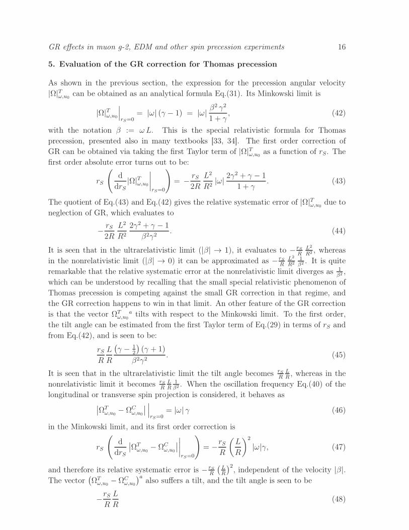
As shown in the previous section, the expression for the precession angular velocity
|Ω|Tω,u0can be obtained as an analytical formula Eq.(31). Its Minkowski limit is
|Ω|Tω,u0
∣
∣
∣
rS=0= |ω| (γ − 1) = |ω| β
2 γ2
1 + γ, (42)
with the notation β := ω L. This is the special relativistic formula for Thomas
precession, presented also in many textbooks [33, 34]. The first order correction of
GR can be obtained via taking the first Taylor term of |Ω|Tω,u0as a function of rS. The
first order absolute error turns out to be:
rS
(
d
drS|Ω|Tω,u0
∣
∣
∣
∣
rS=0
)
= − rS2R
L2
R2|ω| 2γ
2 + γ − 1
1 + γ. (43)
The quotient of Eq.(43) and Eq.(42) gives the relative systematic error of |Ω|Tω,u0due to
neglection of GR, which evaluates to
− rS2R
L2
R2
2γ2 + γ − 1
β2γ2. (44)
It is seen that in the ultrarelativistic limit (|β| → 1), it evaluates to − rSR
L2
R2 , whereas
in the nonrelativistic limit (|β| → 0) it can be approximated as − rSR
L2
R21β2 . It is quite
remarkable that the relative systematic error at the nonrelativistic limit diverges as 1β2 ,
which can be understood by recalling that the small special relativistic phenomenon of
Thomas precession is competing against the small GR correction in that regime, and
the GR correction happens to win in that limit. An other feature of the GR correction
is that the vector ΩTω,u0
a tilts with respect to the Minkowski limit. To the first order,
the tilt angle can be estimated from the first Taylor term of Eq.(29) in terms of rS and
from Eq.(42), and is seen to be:
rSR
L
R
(
γ − 12
)
(γ + 1)
β2γ2. (45)
It is seen that in the ultrarelativistic limit the tilt angle becomes rSR
LR, whereas in the
nonrelativistic limit it becomes rSR
LR
1β2 . When the oscillation frequency Eq.(40) of the
longitudinal or transverse spin projection is considered, it behaves as∣
∣ΩTω,u0
− ΩCω,u0
∣
∣
∣
∣
∣
rS=0= |ω| γ (46)
in the Minkowski limit, and its first order correction is
rS
(
d
drS
∣
∣ΩTω,u0
− ΩCω,u0
∣
∣
∣
∣
∣
∣
rS=0
)
= −rSR
(
L
R
)2
|ω|γ, (47)
and therefore its relative systematic error is − rSR
(
LR
)2, independent of the velocity |β|.
The vector(
ΩTω,u0
− ΩCω,u0
)aalso suffers a tilt, and the tilt angle is seen to be
−rSR
L
R(48)

GR effects in muon g-2, EDM and other spin precession experiments 17
from Eq.(46) and from Eq.(41), independently of the velocity |β|.In the real muon g-2 experiment, the muons are injected with a relativistic Lorentz
dilatation factor γ ≈ 29.3 to the storage ring [4, 7]. This means a velocity relative to
the speed of light |β| ≈ 0.999417412329374, i.e., the muons are ultrarelativistic and
one is in the |β| → 1 limit. Therefore, the Thomas precession frequency as well as the
longitudinal spin oscillation frequency is modified by a relative systematic error of
−rSR
L2
R2(49)
in the muon g-2 experiment. Using now Eq.(49) and the radius and Schwarzschild
radius of the Earth, R ≈ 6.371 · 106m and rS ≈ 9 · 10−3m, and the storage ring radius
L ≈ 7.5m, one infers that the relative systematic error made when neglecting GR in
the estimation of Thomas precession frequency is
≈ −2 · 10−21, (50)
which is negligible, given the present experimental accuracy. The most sensitive
observable to the GR correction seems to be the tilt of the spin precession plane against
the nominal horizontal plane, which is ≈1.7 · 10−15 1β2 radians with the parameters of
the existing g-2 magnet setup. It is seen that an experimental detection of GR effects
are only possible with sufficiently low |β| and sufficiently large angular resolution, which
is not realistic e.g. in a muon g-2 experiment. Moreover in the above corrections the
effects of GR on the electrodynamics of the beam optics is not yet accounted for, which
we quantify in the coming sections.
6. Electromagnetic fields in an idealized storage ring over Schwarzschild
In this section, the electromagnetic fields in an idealized storage ring [7] over a
Schwarzschild background spacetime is outlined, which guides the particle beam along
the nominal beam trajectory Eq.(2).
The most important electromagnetic field in a storage ring is usually, a homogeneous
magnetic field, which forces the particles onto a closed circular orbit at the nominal
trajectory. The first task is to define such a field configuration over our Schwarzschild
background. In order to do that, recall that the outward pointing unit normal vector
field of the surface r = const surface is called the radial unit vector field, and is denoted
by ra. Its components in our coordinate conventions are
ra(t, r, ϑ, ϕ) =
0√
1− rSr
0
0
. (51)
The intersection of an r = const surface with a Killing time t = const surface is a
two-sphere. The induced metric gab+ rarb on it is just the round two-sphere metric with
radius r. Besides the induced metric, on the pertinent surface the embedded flat metric
can also be defined by gab + rarb − dradrb, where dr denotes the exterior derivative of

GR effects in muon g-2, EDM and other spin precession experiments 18
the radius function r. This surface has a vector field on it defined by taking the radial
unit vector field at a preferred point, and parallel transporting it to any point of the
two-sphere along a geodesic, in terms of the embedded flat metric. That vector field,
when initialized from the storage ring axis, i.e., from ϑ = 0, is denoted by va, and is
called the vertical unit vector field. Its components in our coordinate conventions are
va(t, r, ϑ, ϕ) =
0
cosϑ
−1rsinϑ
0
. (52)
Note that the unit length and the parallel transport is understood in the embedded
flat metric on the surface, and not in the merely restricted Schwarzschild metric to the
surface. These vector fields and their geometric construction is illustrated in Fig. 3.
r=const, t=const surface
radial vector field
r=const, t=const surface
parallel transportalong geodesic
initial radial vector
vertical vector field
Figure 3. Left panel: illustration of the outward pointing radial unit vector field
ra on an r = const, t = const surface. Right panel: illustration of the geometric
construction of the vertical unit vector field va on an r = const, t = const surface. The
outward pointing radial unit vector field is taken at a preferred point, and it is parallel
transported along geodesics to other points of the surface, in terms of the embedded
flat metric.
The static, axisymmetric, homogeneous vertical magnetic vector field Ba, which
forces the particles on a cyclotronic motion in the storage ring, is simply defined by a
radial scalar multiple of the vertical unit vector field va. Namely, one has the ansatz
Ba(t, r, ϑ, ϕ) = b(r) va(t, r, ϑ, ϕ) with r 7→ b(r) being a radial function such that the
electromagnetic field corresponding to Ba satisfies the vacuum Maxwell equations [36].
This implies that in our coordinates it has the components
Ba(t, r, ϑ, ϕ) = B
√
1− rSr
1− rSR
(
LR
)2
0
cos ϑ
−1rsinϑ
0
, (53)
with B being a constant. It is normalized such that on the r = R and ϑ = Θ
surface, it has pseudolength equal to the constant |B|. The magnetic component of

GR effects in muon g-2, EDM and other spin precession experiments 19
our electromagnetic field is defined by the Hodge dual of Ba in the laboratory frame u0:
FBbc := −u0
a√
−det(g)ǫabcd Bd. (54)
Direct substitution shows that FBbc satisfies the vacuum Maxwell equations over
Schwarzschild spacetime.
In the muon g-2 or EDM experimental settings [7], an electrostatic beam focusing
optics is used to maintain the beam stability. Since this beam optics is standing
on the Earth’s surface together with the storage ring, on the average it exerts a
radial electrostatic field at the nominal trajectory, balancing the beam against falling
towards the Earth. This electrostatic field, being radial, has the form ERa(t, r, ϑ, ϕ) =
e(r) ra(t, r, ϑ, ϕ), where the radial function r 7→ e(r) has to be chosen such that the
electromagnetic field corresponding to ERa satisfies the vacuum Maxwell equations.
This implies that in our coordinates it has components
ERa(t, r, ϑ, ϕ) = ER
R2
r2
0√
1− rSr
0
0
, (55)
with ER being a constant. It is normalized such that on the r = R surface, it has
pseudolength equal to the constant |ER|. The electric component of our electromagnetic
field is defined by ERa and u0:
FER
ab := u0cgcaER
dgdb − u0cgcbER
dgda. (56)
Direct substitution shows that FER
ab satisfies the vacuum Maxwell equations over
Schwarzschild spacetime.
In the EDM experimental settings [7], sometimes a mixed electrostatic-
magnetostatic storage ring is used, or a pure electrostatic storage ring. These employ
an outward pointing cylindrical electrostatic field, being the electric field of a uniformly
charged infinite wire in an idealized model. The field of such a wire could be directly
calculated, since the Green’s function of electrostatics/magnetostatics is well understood
over a Schwarzschild background [37]. The evaluation of the pertinent Green’s integral
over the wire, however, becomes quite complicated if one would like an analytical
formula. Therefore, it is easier to construct the pertinent field configuration using
symmetry ansatzes. As it is well-known, in the Minkowski limit, the field of such
a uniformly charged wire, comoving with the observer u0, and placed at ϑ = 0 and
ϑ = π is known to be a cylindric one, with field strength decaying like ∼ 1r sinϑ
, and
its electrostatic potential being of the form ∼ ln (r sinϑ) + const. Our ansatz over the
Schwarzschild background therefore shall be that the electromagnetic vector potential
has the form
Aa(t, r, ϑ, ϕ) =(
f(r) ln(sin ϑ) + g(r), 0, 0, 0)
(57)
which should solve the vacuum Maxwell equations for r > rS, outside the wire singularity
ϑ = 0 and ϑ = π. That requirement determines the unknown radial functions f(r) and

GR effects in muon g-2, EDM and other spin precession experiments 20
g(r) up to four integration constants a, b, c, d, and one arrives at the solution
At(t, r, ϑ, ϕ) = a(
ln(sinϑ) +(
1− rSr
)
ln(r − rS))
+ b
(
1
rln(sinϑ)− 1
rSln(r) +
1
rS
(
1− rSr
)
ln(r − rS)
)
− c1
r+ d. (58)
Since the field strength tensor is the exterior derivative of Aa, it is invariant to the
choice of the integration constant d, and thus one may set d = 0 by convention.
Also, the Maxwell’s equations are linear, and thus the shape of the field configuration
is invariant to the normalization of the solution, and therefore, e.g., one may set
a = 1 by convention, in order to determine the shape of the field. Given these
choices, the total charge within an r = const sphere of a solution Eq.(58) evaluates as∫
S2(r=const)
(∗dA) = 2π (2 (−r − (b+ rS) ln(r − rS)− c) + b 2 (ln(2)− 1)). If one requires
that the charge under the r = const two-spheres should not diverge as r → rS, the
equality b = −rS follows. With this condition, the charge under an r = const two-sphere
shall be 2π (2 (−r − c)− rS 2 (ln(2)− 1)), meaning that the charge density in terms of
r along the wire is uniform, as illustrated in Fig. 4. The last integration constant c
can be fixed by requiring that the charge under the sphere r = rS must vanish, and
then c = −rS ln(2) follows. Thus, the field strength tensor FEH
ab of a uniformly charged
vertical wire suspended over a Schwarzschild background becomes a constant factor
times dA, with A taken from Eq.(58) and a = 1, b = −rS, c = −rS ln(2), d = 0. If
one wishes to express that in terms of an electric vector field EHa in the space of the
observer u0, defined in terms of FEH
ab = u0cgcaEH
dgdb − u0cgcbEH
dgda, then one arrives
at the expression
EHa(t, r, ϑ, ϕ) = EH
L
r sin ϑ
√
1− rSrNrS
0
sin ϑ(
1 + rSrln(1
2sin ϑ)
)
1rcosϑ
0
,
with NrS :=((L
R
)2(
1 +rSR
ln( L
2R
))2
+(
1−(L
R
)2)(
1− rSR
))− 12
(59)
where the normalization factor EH is a real constant. The symbol NrS was introduced
for brevity. The formula is normalized such that at the r = R, ϑ = Θ location of
the nominal beam line, the vector field EHa has pseudolength equal to the constant
|EH |. As a cross-check, direct evaluation also shows that the field strength tensor
FEH
ab = u0cgcaEH
dgdb−u0cgcbEH
dgda indeed satisfies the vacuum Maxwell equations over
Schwarzschild spacetime.
The total electromagnetic field strength tensor is then Fab := FBab +FEH
ab +FER
ab . In
our coordinates, it has the components:

GR effects in muon g-2, EDM and other spin precession experiments 21
r=rS
asymptotically cylindricelectric field
charged wire
r=constr=const
Figure 4. Illustration of the asymptotically cylindric electrostatic field of a
uniformly charged wire suspended in a Schwarzschild spacetime. This field models
the asymptotically horizontal electric field in an electrostatic or in a mixed magnetic-
electric storage ring. The charge density of the wire can be determined by the charge
integral under r = const two-spheres, as described in the text. The free integration
constants of such Maxwell fields are set so that the wire has uniform charge density in
terms of r, and that under the sphere r = rS one has vanishing total charge.
Fab(t, r, ϑ, ϕ) =
0 −ERR2
r20 0
ERR2
r20 0 −B r sin2 ϑ
√
1− rSR (L
R)2
0 0 0 −B r2 sinϑ cos ϑ√
1− rSR (L
R)2
0 B r sin2 ϑ√
1− rSR (L
R)2 B r2 sinϑ cosϑ
√
1− rSR (L
R)2 0
+EH LNrS
0 −1r(1 + rS
rln (1
2sin ϑ)) −(1− rS
r) cosϑ
sinϑ0
1r(1 + rS
rln (1
2sin ϑ)) 0 0 0
(1− rSr) cosϑ
sinϑ0 0 0
0 0 0 0
.
(60)If the storage ring is purely magnetic, then B 6= 0, EH = 0, ER 6= 0, whereas for a
purely electrostatic storage ring one has B = 0, EH 6= 0, ER 6= 0, while for a mixed
magnetic-electric ring one has B 6= 0, EH 6= 0, ER 6= 0.

GR effects in muon g-2, EDM and other spin precession experiments 22
7. The absolute Larmor rotation in presence of electromagnetic fields
Whenever electromagnetic field is also present, the BMT equation, i.e., the second
equation in Eq.(7), causes further rotation of the spin direction vector in addition to
the Thomas rotation, the so-called Larmor rotation.
The beam motion is modelled by the cyclotronic worldline Eq.(2), and it has to
satisfy the Newton equation, i.e., the first line of Eq.(7), against the field strength
tensor Eq.(60). Given ω and EH , that is fulfilled whenever the consistency conditions
B = ωmγ
q
√
1− rSR
(
L
R
)2
+EH
ω LNrS
√
1− rSR
√
1− rSR
(
L
R
)2
,
ER =rSR
mγ
2 q R
1√
1− rSR
− EH
L
R
rSR
NrS
(
1 + ln
(
L
2R
))
(61)
hold with the notation γ := 1√1−ω2L2 . These are the equations of cyclotronic motion over
a Schwarzschild background spacetime, with ω being the cyclotron circular frequency
in terms of u0-proper time. From this point on, it is assumed that Eq.(61) is satisfied,
i.e., that the motion Eq.(2) of the particle is a consequence of a cyclotronic motion
in electromagnetic field over a Schwarzschild spacetime. In the real g-2 and EDM
experiments [4, 7] the magnetic field strength B and the horizontal electric field strength
EH are the fixed (measured) parameters, which determine ω and ER, given the constantsmq, L, R, and the GR correction parameter rS
R.
We are now at the point of evaluating the Larmor tensor Lωbd :=
−Λωµ
s
(
gbcFcd − uωbuω
cFcd − gbcFceuωeuω
fgfd)
which gives a contribution to the BMT
equation, i.e., to the second line of Eq.(7). With that definition, the spin transport
equation reads as
d
dtwω
b(t) = Fωbc wω
c(t) + Lωbc wω
c(t) (62)
in terms of Killing time. In our coordinate conventions it has components as

GR effects in muon g-2, EDM and other spin precession experiments 23
Lωbd = −1
2
g ω√
1− rSR
1− ω2L2
0 −ωLLR
(1− 32
rSR )
(1− rSR )
32
−ωLR
√
1−(LR)
2
(1− rSR )
12
0
−ωLLR
(
1− 32rSR
) (
1− rSR
)12 0 0 LL
R
(
1− 32rSR
)
−ω LR
√
1−(
LR
)2 (1− rS
R
)12 0 0 L
R
√
1−(
LR
)2
0 − 1R
(1− 32
rSR )
(1− rSR )
−RL
√
1−(
LR
)20
−g q EH
√1− ω2L2
2mωLNrS
(
1− rSR
)2
0 −ωLLR
1
(1− rSR )
32
−ωLR
√
1−(LR)
2
(1− rSR )
32
0
−ωLLR
(
1− rSR
)12 0 0 LL
R
−ω LR
√
1−(LR)
2
(1− rSR )
12
0 0 LR
√
1−(LR)
2
1− rSR
0 − 1R
1
(1− rSR )
−RL
√
1−(LR)
2
1− rSR
0
(63)where the usual definition of the gyromagnetic factor g := 2mµ
q swas used. By
construction, or by direct substitution it is seen that the tensor Lωab g
bc is antisymmetric,
and therefore Lωab corresponds to a Lorentz transformation generator. Moreover,
Lωab uω
b = 0 holds, which means that Lωab describes an uω
a-rotation generator. That
phenomenon is the Larmor rotation, and is an absolute, observer independent effect.
8. The relative Larmor precession as seen by the laboratory observer
Because of Eq.(62), according to the laboratory observer u0, the spin direction vector
wω,u0a satisfies the equation
(
wω,u0
f)′
= ΦTω,u0
fb wω,u0
b + ΦLω,u0
fb wω,u0
b, (64)
with the definition ΦLω,u0
fb := 1
Λ0Bu0,uω
fc Lω
caBuω ,u0
ab. By construction or by direct
substitution it is seen that ΦLω,u0
fb g
bc is antisymmetric, which means that it describes a
Lorentz transformation generator. Moreover, ΦLω,u0
fb u0
b = 0 holds, which means that it
describes an u0-rotation generator. The effect of ΦLω,u0
fb is called the Larmor precession.

GR effects in muon g-2, EDM and other spin precession experiments 24
In our coordinate conventions, it has the components
ΦLω,u0
ab =
0 0 0 0
0 0 0 ΦLω,u0
rϕ
0 0 0 ΦLω,u0
ϑϕ
0 ΦLω,u0
ϕr ΦL
ω,u0
ϕϑ 0
,
with
ΦLω,u0
ϕr = − ΦL
ω,u0
rϕ
gϕϕ
grr,
ΦLω,u0
ϕϑ = − ΦL
ω,u0
ϑϕ
gϕϕ
gϑϑ,
ΦLω,u0
rϕ = − 1
2g ω Lγ
L
R
(
1− 3
2
rSR
)
− g q
2m
EH LNrS
(
1− rSR
) 32
ωR γ2,
ΦLω,u0
ϑϕ = − 1
2g ω γ
L
R
√
1− L2
R2− g q
2m
EH NrS
√
1− rSR
ωRγ2
√
1− L2
R2(65)
with using the notation γ := 1√1−ω2L2 .
The angular velocity vector of the Larmor precession can be obtained by the u0
spatial Hodge dual of ΦLω,u0
ab, according to the definition
ΩLω,u0
f :=1
2u0
a√
−det(g)ǫabcd gbf ΦL
ω,u0
ce g
ed. (66)
Its components in our coordinate conventions are
ΩLω,u0
a =
0
−12g ω γ
√
1− L2
R2
√
1− rSR
− g q
2m
EH NrS (1−rSR )
√
1−L2
R2
ω Lγ2
12gω γ 1
RLR
1− 32
rSR√
1− rSR
+ g q
2m
EH NrS (1−rSR )
ωR2 γ2
0
.
(67)
For charged particles in a cyclotronic motion, the total angular velocity vector of
the spin precession is determined by ΩSω,u0
a := ΩTω,u0
a + ΩLω,u0
a. Its components in our
coordinate conventions are
ΩSω,u0
a =
0
−ω (1 + γ a)√
1− rSR
√
1− L2
R2 − (1 + a)EH qNrS (1−
rSR )
√
1−L2
R2
mωLγ2
ω 1R
LR
(
√
1− rSR+ γ a
1− 32
rSR√
1− rSR
)
+ (1 + a)EH qNrS (1−
rSR )
mωR2 γ2
0
,
(68)where the usual notation a := g−2
2was used for the magnetic moment anomaly. The
metric projections onto the orthonormal frame ra, ϑa, ϕa of ΩSω,u0
a are the followings:

GR effects in muon g-2, EDM and other spin precession experiments 25
−gab raΩS
ω,u0
b = − ω (1 + γ a)
√
1− L2
R2− (1 + a)
EH qNrS
(
1− rSR
)12
√
1− L2
R2
mωLγ2,
−gab ϑa ΩS
ω,u0
b = ωL
R
(
√
1− rSR
+ γ a1− 3
2rSR
√
1− rSR
)
+ (1 + a)EH qNrS
(
1− rSR
)
mωRγ2,
−gab ϕaΩS
ω,u0
b = 0. (69)
As discussed at the end of Section 4, the oscillation frequencies of the
longitudinal and transverse spin component is determined by the length of the vector(
ΩSω,u0
− ΩCω,u0
)a. The coordinate components of that vector is given by
(
ΩSω,u0
− ΩCω,u0
)a= ω γ a
0
−(
1− rSR
)12
√
1− L2
R2
1R
LR
1− 32
rSR
(1− rSR )
12
0
+(1 + a)EH q
mω Lγ2
0
−NrS
(
1− rSR
)
√
1− L2
R2
1R
LRNrS
(
1− rSR
)
0
. (70)
Its metric projections onto ra, ϑa, ϕa is
−gab ra(
ΩSω,u0
− ΩCω,u0
)b= − ω γ a
√
1− L2
R2
− (1 + a)EH qNrS
(
1− rSR
)12
mωLγ2
√
1− L2
R2,
−gab ϑa(
ΩSω,u0
− ΩCω,u0
)b= ω γ a
L
R
1− 32rSR
(
1− rSR
)12
+ (1 + a)EH qNrS
(
1− rSR
)
mωLγ2
L
R,
−gab ϕa(
ΩSω,u0
− ΩCω,u0
)b= 0. (71)
In the g-2 experiments [4, 7], one has B 6= 0 and EH = 0, i.e., purely magnetic
storage ring is used, and the main observable is
∣
∣ΩSω,u0
− ΩCω,u0
∣
∣ = |ω a| γ(
(
1− L2
R2
)
+L2
R2
(1− 32rSR)2
1− rSR
)12
. (72)
It is seen, that GR gives slight contribution, the quantification of which is done in the
following section.
In electric dipole moment (EDM) search experiments [12, 13, 14], the so called
frozen spin method is used: the parameters B and EH are adjusted such, that the
vector(
ΩSω,u0
− ΩCω,u0
)avanishes to a best possible accuracy, and thus the observed spin
direction vector is always exactly tangential to the orbit, i.e., points in the direction

GR effects in muon g-2, EDM and other spin precession experiments 26
ϕa. If an EDM of the particle would exist, it manifests as a residual precession, out
of the orbital plane. The identities Eq.(61) and Eq.(70) tell us that in the Minkowski
limit (rS = 0), the frozen spin condition is quite possible to achieve via setting EH =
− a1+a
mqLω2 γ3, assuming that the magnetic anomaly a of the particle was measured
in advance. In the GR case, however, the complete vanishing of(
ΩSω,u0
− ΩCω,u0
)ais
not possible to achieve exactly, and at best the frozen spin condition can only be
achieved approximately. For instance, one may require that the vertical projection
−gab va(
ΩSω,u0
− ΩCω,u0
)bvanishes, which is fulfilled whenever
EH = − a
1 + a
m
qLω2 γ3 1
NrS
(
1− rSR
)12
1− 32rSR
L2
R2
1− rSR
L2
R2
(73)
holds, as seen from Eq.(70). In that case, there will be a residual precession out of the
orbital plane, with magnitude
∣
∣ΩSω,u0
− ΩCω,u0
∣
∣ = |ω a| γ 1
2
rSR
L
R
(
1− rSR
)− 12
√
1− L2
R2
√
1− rSR
L2
R2
(74)
and the direction of the precession is upward vertical whenever −ω a is positive, and
downward vertical otherwise. The magnitude of this GR correction to a frozen spin
scenario is quantified in the next section.
9. Evaluation of the GR corrections to Thomas plus Larmor precession
First, the effect of GR is evaluated on the cyclotron frequency ω. This frequency is
uniquely determined by the first line of Eq.(61), given the vertical magnetic field strength
B and the horizontal electric field strength EH of the storage ring, and the constantsmq, L, R, along with the GR correction parameter rS
R. In order to determine the rS
dependence of ω, it should be regarded as an implicit function of rS. Its first order GR
correction is nothing but its first Taylor expansion term in terms of rS, and that can be
easily derived by differentiating against rS the pertinent consistency equation between
ω, B and EH . It follows that one has
rS
(
d
drSω
∣
∣
∣
∣
rS=0
)
= ω1
2
rSR
L2
R2
1− 1γ2 +
2EH q L(1+ln( L2R))
mγ
γ2 − 1− EH q L
mγ
. (75)
The last quotient expression is ≈1 for relativistic particles, and thus the relative error of
ω caused by the neglection of GR is ≈ 12
rSR
L2
R2 , which is of the order of 10−21, as already
quantified in Section 5. Therefore, that correction is pretty much negligible for current
and foreseeable experimental applications. One could also say, that in the system there
are two small parameters: rSR
and LR, and the corrections of the third order, such as rS
RL2
R2 ,
are considered to be negligible. That also means that in the GR correction estimations,
the rS dependence of ω can be neglected in order to simplify the formulas.
As a next step, the effect of GR on the main observable of the muon g-2 experiments
[4, 7] is evaluated, which is the frequency of the longitudinal spin projection. That was

GR effects in muon g-2, EDM and other spin precession experiments 27
shown equal to the quantity∣
∣ΩSω,u0
− ΩCω,u0
∣
∣, which was shown to take the form Eq.(72)
in a purely magnetic g-2 ring (B 6= 0, EH = 0). In the Minkowski limit, this has its well
known special relativistic form∣
∣ΩSω,u0
− ΩCω,u0
∣
∣
∣
∣
∣
rS=0= |ω a| γ, (76)
which is the principal formula for g-2 determination. Its first order Taylor expansion
term in terms of rS is seen to be
rS
(
d
drS
∣
∣ΩSω,u0
− ΩCω,u0
∣
∣
∣
∣
∣
∣
rS=0
)
= −|ω a| γ rSR
L2
R2, (77)
causing a relative systematic error of − rSR
L2
R2 , being negligible, of the order of −2 ·10−21.
Therefore, that correction is negligible for current g-2 experimental applications. (For
simplicity, the tiny rS dependent correction of ω, quantified in Eq.(75), was neglected
in the formula.)
The first apparent sizable GR correction can be seen in the total spin precession
vector ΩSω,u0
a. Namely, whenever one uses a purely magnetic storage ring (B 6= 0,
EH = 0) with a particle with magnetic anomaly −1 < a < 0, such as deuteron
nuclei which do have a ≈ −0.142 [38], then there exists a unique velocity (or B)
setting for which 1 + a γ = 0 holds. As seen from Eq.(69), in that case the spin
precession vector ΩSω,u0
a vanishes in the Minkowski limit (rS = 0), meaning that the spin
direction vector is merely parallel transported in the space of the laboratory observer.
One could call such a scenario a “zero torque setting”. In the GR case, however,
a small approximately horizontal component of ΩSω,u0
a persists, of the magnitude∣
∣ΩSω,u0
∣
∣ =
∣
∣
∣
∣
ω LR
(
√
1− rSR− 1− 3
2
rSR√
1− rSR
)∣
∣
∣
∣
, as seen from Eq.(69). Taking its first Taylor
term in rS, this is of the magnitude β rS2R2 with the notation β := ω L, being the circular
velocity in units of speed of light. When translated to ordinary units from the used
geometric units, this is nothing but β g
cwith g denoting the gravitational acceleration
on the Earth’s surface, and c denoting the speed of light. This residual precession
quantifies as ≈3.26 · 10−8 rad/sec if one assumes a deuteron beam, which shall satisfy
1 + a γ = 0 at β ≈ 0.9804. In such a configuration with an initially tangential spin
vector, the spin will not merely be parallelly transported as in the Minkowski limit, but
it will tilt in and out of the orbital plane. The amplitude of this vertical polarization
buildup is, however, too small to experimentally measure. That is because the spin
vector is not approximately perpendicular to the residual ΩSω,u0
a vector at all times,
and thus the polarization does not accumulate with elapsing time. That issue can be
remedied with an experimental setting discussed below.
The GR correction is expected to have a measurable effect on frozen spin
experiments, such as EDM search experiments [12, 13, 14]. For these settings, in the
Minkowski limit, the spin direction vector always follows the tangent of the orbit curve,
i.e.,(
ΩSω,u0
− ΩCω,u0
)a∣
∣
∣
rS=0= 0 holds. In case of GR, there are no such parameter settings
when this frozen spin condition holds, but as indicated previously, one may can choose

GR effects in muon g-2, EDM and other spin precession experiments 28
a setting in which case the vertical projection of the vector(
ΩSω,u0
− ΩCω,u0
)avanishes.
In that case, the residual precession shall elevate the spin direction vector out of the
orbital plane, with a rate Eq.(74). Again, in order to quantify that, we take its first
Taylor expansion term in terms of rS, which is
rS
(
d
drS
∣
∣ΩSω,u0
− ΩCω,u0
∣
∣
∣
∣
∣
∣
rS=0
)
= |ω a| γ 1
2
rSR
L
R
√
1− L2
R2. (78)
Taking into account that LR
≪ 1 and β = ω L, this quantifies as |a βγ| rS2R2 . When
translated from the geometric units to normal units, it corresponds to the expression
|a βγ| gc
(79)
which quantifies as ≈ |a βγ| 3.26 · 10−8 rad/sec.§ Thus, in this setting, given an initially
longitudinally polarized beam, a vertical polarization buildup will be seen at the rate
of∣
∣ΩSω,u0
− ΩCω,u0
∣
∣ ≈ |a βγ| 32.6 nrad/sec, as shown in Fig. 5. This magnitude of
polarization buildup rate is well within the experimental reach for the planned EDM
experiments [12, 13, 14], since the spin coherence of e.g. proton beams can be maintained
for about an hour with today’s beam technology. Therefore, we propose to use the
foreseen frozen spin or EDM experiment also as sensitive GR experiments on spin
propagation. Although the fake EDM signal by GR is much larger than an expected
true EDM signal, they are distinguishable due to their opposite sign flip behavior for a
change of the beam circulation direction, i.e., due to their opposite chirality behavior.
10. Concluding remarks
In this paper, a fully general relativistic calculation was performed in order to evaluate
the GR corrections over a Schwarzschild background for particle spin precession
experiments, such as the muon g-2 measurement [4] or the electric dipole moment
(EDM) search experiments [12, 13, 14]. It turns out that although GR gives a first
order correction in rS for certain important observables, its contribution to the muon
g-2 measurements is negligible. That is because in that setting spin precession in the
horizontal plane is studied, and GR mainly gives contribution to the other direction,
moreover the amount of precession due to the g-2 signal is large anyway. However, for
§ Our formula Eq.(79) is also in accordance with the post-Newtonian approximative results of [21],
which was obtained for the special case of a purely electrostatic (B = 0, EH 6= 0) frozen spin storage
ring. In such a ring, the Newton equation Eq.(61) and the frozen spin condition Eq.(73) as well as the
zero magnetic field condition B = 0 needs to be satisfied at the same time, in the rS = 0 limit. That
is only possible for particles with a > 0, and also singles out a so-called magic momentum β γ = 1√
a
which is necessary in order to satisfy all these conditions. The residual vertical precession due to
GR contribution is seen in that special case to be√a g
c, by means of Eq.(79), which confirms the
calculation of [21]. It is seen, however, that using a mixed magnetic-electric frozen spin storage ring
might be more advantageous, since it can be applied to any a, and does not single out a small value for
the Lorentz factor γ. Indeed, via using large γ, the GR effect can be arbitrarily magnified. Therefore,
for a specific GR experiment, we propose to use a mixed magnetic-electric frozen spin ring, with as
large γ as possible, and particles with large a.

GR effects in muon g-2, EDM and other spin precession experiments 29
Initial, purely tangential spin vector
Nominal beamline orbit
Slowly built up vertical spin polarization due to GR
Figure 5. Illustration of the effect of GR corrections to a frozen spin setting. The
GR correction results in a slow buildup of vertical spin polarization, if the beam was
initially longitudinally polarized. The rate of the polarization buildup is given by
Eq.(79).
EDM search experiments, in which case a so-called frozen spin situation is obtained with
a combination of the γ factor and of the electric and magnetic fields, the GR effects
imitate a fake EDM signal. That is a precession out of the orbital plane, of the magnitude
|a βγ| g/c, being of the order of 3.26 · 10−8 rad/sec, which is well above the planned
sensitivity of ≈10−9 rad/sec of these experiments, and pretty much above the Standard
Model (SM) expectation. Thus, the EDM experiments provide a unique platform for
experimental test of GR in terms of particle spin propagation. Moreover, in any frozen
spin experiment with aimed precision not worse than 10−6 rad/sec, the GR signal needs
to be subtracted in order to access any signature coming from particle physics — SM
or BSM. Fortunately, direct experimental elimination of such backgrounds may also be
achieved by comparing the effect as seen from normally and reversely rotating beams,
since the GR effect would change sign, but the EDM effect would not [12, 13, 14]. If
such subtraction is done, the GR signal is expected to be distinguishable from a real
EDM signal and vice versa.
Acknowledgments
The authors would like to thank Ferenc Siklér and Dezső Horváth for the motivating
discussions. The very useful technical discussions with Richard M. Talman on the frozen
spin EDM experiments and with Zoltán Keresztes on the BMT equation is also greatly
acknowledged. This work was supported in part by the Hungarian Scientific Research
fund (NKFIH 123959) and the János Bolyai Research Scholarship of the Hungarian
Academy of Sciences.

GR effects in muon g-2, EDM and other spin precession experiments 30
References
[1] T. Morishima, T. Futamase, H. M. Shimizu: The general relativistic effects on the magnetic
moment in Earth’s gravity; Prog. Theor. Exp. Phys. 2018 (2018) 063B07 [arXiv:1801.10244].
[2] T. Morishima, T. Futamase, H. M. Shimizu: Post-Newtonian effects of Dirac particle in curved
spacetime - II : the electron g-2 in the Earth’s gravity; [arXiv:1801.10245].
[3] T. Morishima, T. Futamase, H. M. Shimizu: Post-Newtonian effects of Dirac particle in curved
spacetime - III : the muon g-2 in the Earth’s gravity; [arXiv:1801.10246].
[4] The Muon g-2 experiment [http://muon-g-2.fnal.gov].
[5] G. W. Bennett et al: Final report of the E821 muon anomalous magnetic moment measurement
at BNL; Phys. Rev. D 73 (2006) 072003 [arXiv:hep-ex/0602035].
[6] J. P. Miller, E. de Rafael, B. L. Roberts: Muon (g-2): Experiment and Theory;
Rept. Prog. Phys. 70 (2007) 795 [arXiv:hep-ph/0703049].
[7] S. R. Mane, Y. M. Shatunov, K. Yokoya: Spin-polarized charged particle beams in high-energy
accelerators ; Rept. Prog. Phys. 68 (2005) 1997.
[8] M. Visser: Post-Newtonian particle physics in curved spacetime; [arXiv:1802.00651].
[9] P. Guzowski: The effect of Earth’s gravitational field on the muon magic momentum;
[arXiv:1802.01120].
[10] H. Nikolic: Can effective muon g-2 depend on the gravitational potential? ; [arXiv:1802.04025].
[11] C. Lämmerzahl, G. Neugebauer: The Lense-Thirring Effect: From the Basic Notions to the
Observed Effects ; In: C Lämmerzahl, C. W. F. Everitt, F. W. Hehl (eds) Gyros, Clocks,
Interferometers: Testing Relativistic Graviy in Space, Lecture Notes in Physics, vol 562 Springer
(2001).
[12] Y. Senichev et al: Quasi-frozen spin concept of deuteron storage ring as an instrument to search
for electric dipole moment ; Proceedings of IPAC2017 (2017) TUPVA084, 2275.
[13] Y. Semertzidis: Storage ring EDM experiments; Eur. Phys. J. Web. Conf. 118 (2016) 01032.
[14] R. Talman: The Electric Dipole Moment Challenge; IOP Concise Physics (2017).
[15] Gravity Probe B experiment [https://einstein.stanford.edu].
[16] C. W. F. Everitt et al: Gravity Probe B: Final Results of a Space Experiment to Test General
Relativity; Phys. Rev. Lett. 106 (2011) 221101 [arXiv:1105.3456].
[17] A. Kobach: Gravitational effects on measurements of the muon dipole moments ; Nucl. Phys. B911
(2016) 206 [arXiv:1603.00127].
[18] A. J. Silenko, O. V. Terayev: Equivalence principle and experimental tests of gravitational spin
effects ; Phys. Rev. D76 (2007) 061101 [arXiv:gr-qc/0612103].
[19] Y. N. Obukov, A. J. Silenko, O. V. Terayev: Manifestations of the rotation and gravity of the
Earth in high-energy physics experiments; Phys. Rev. D94 (2016) 044019 [arXiv:1608.03808].
[20] Y. N. Obukov, A. J. Silenko, O. V. Terayev: Manifestations of the rotation and gravity of the
Earth in spin physics experiments; Int. J. Mod. Phys. A31 (2016) 1645030.
[21] Y. Orlov, E. Flanagan, Y. Semertzidis: Spin rotation by Earth’s gravitational field in a “frozen-
spin” ring; Phys. Lett. A376 (2012) 2822.
[22] S. Hawking, G. F. R. Ellis: Large Scale Structure of Spacetime; Cambridge University Press (1973).
[23] R. M. Wald: General Relativity; Chicago University Press (1984).
[24] M. Conte, R. Jagannathan, S. A. Khan, M. Pusterla: Beam optics of the Dirac particle with
anomalous magnetic moment ; Particle Accelerators 56 (1996) 99.
[25] J. D. Jackson: Classical Electrodynamics ; Wiley (1999).
[26] M. Mathisson: Neue Mechanik materieller Systeme; Acta. Phys. Polon. 6 (1937) 163.
[27] A. Papapetrou: Equations of motion in general relativity; Proc. Phys. Soc. 64 (1951) 57.
[28] W. G. Dixon: A Covariant Multipole Formalism for Extended Test Bodies in General Relativity;
Nouvo Cimento 34 (1964) 317.
[29] W. G. Dixon: Classical theory of charged particles with spin and the classical limit of the Dirac
equation; Nuovo Cimento 38 (1965) 1616.

GR effects in muon g-2, EDM and other spin precession experiments 31
[30] A. A. Deriglazov, W. G. Ramírez: Recent progress on the description of relativistic spin: vector
model of spinning particle and rotating body with gravimagnetic moment in General Relativity;
Adv. Math. Phys. 2017 (2017) 7397159 [arXiv:1710.07135].
[31] F. A. E. Pirani: On the Physical significance of the Riemann tensor ; Acta Phys. Polon. 15 (1956)
389.
[32] W. M. Tulczyjew: Motion of multipole particles in general relativity theory; Acta Phys. Polon. 18
(1959) 393.
[33] W. Rindler: Relativity: Special, General, and Cosmological ; Oxford University Press (2006).
[34] T. Matolcsi, M. Matolcsi, T. Tasnádi: On the relation of Thomas rotation and angular velocity of
reference frames; Gen. Rel. Grav. 39 (2007) 413 [arXiv:math-ph/0611047].
[35] GRTensorII [http://grtensor.phy.queensu.ca].
[36] R. S. Hanni, R. Ruffini: Schwarzschild black hole in an asymptotically uniform magnetic field ;
Lett. Nuovo Cimento 15 (1976) 189.
[37] L. Binet: Electrostatics and magnetostatics in the Schwarzschild metric; J. Phys. A9 (1976) 1081.
[38] N. J. Stone: Table of nuclear magnetic dipole and electric quadrupole moments ; Atomic Data and
Nuclear Data Tables 90 (2005) 75.