
Quality of Service Scheduling for 802.16 Broadband Wireless Access Systems
Quality of Service & Scheduling
C. PhamUniv. Lyon 1
Slides mostly taken from Shivkumar Kalyanaraman which are based in part on slides of Ion Stoica, Jim Kurose, Srini Seshan, Srini Keshav

Multimedia, real time on the Internet
❒ Real-time applications❍ Interactive applications are sensitive to packet delays
(telephone)❍ Non-interactive applications can adapt to a wider range
of packet delays (audio, video broadcasts)❍ Guarantee of maximum delay is useful
ArrivalOffsetGraph
PlayoutPoint
Sampled Audio
Playout Buffer must be small for interactive applications

Time-constrained applications
❒ Elastic applications❍ Interactive data transfer (e.g. HTTP, FTP)
• Sensitive to the average delay, not to the distribution tail
❍ Bulk data transfer (e.g. mail and news delivery)• Delay insensitive
❍ Best effort works well
Document
Document is only useful when it is completely received. This means average packet delay is important, not maximum packet delay.Document

Discussion
❒ What is the problem?❍ Different applications have different delay, bandwidth,
and jitter needs❍ Some applications are very sensitive to changing network
conditions: the packet arrival time distribution is important
❒ Solutions❍ Make applications adaptive❍ Build more flexibility into network

Why Better-than-Best-Effort (QoS)?
❒ To support a wider range of applications❍ Real-time, Multimedia, etc
❒ To develop sustainable economic models and new private networking services
❍ Current flat priced models, and best-effort services do not cut it for businesses

Qualit y of Ser vice: What is it ?
Multimedia applications: network audio and video
network provides application with level of performance needed for application to function.
QoS

What is QoS?
❒ “Better performance” as described by a set of parameters or measured by a set of metrics.
❒ Generic parameters: ❍ Bandwidth❍ Delay, Delay-jitter❍ Packet loss rate (or loss probability)
❒ Transport/Application-specific parameters:❍ Timeouts❍ Percentage of “important” packets lost

What is QoS (contd) ?
❒ These parameters can be measured at several granularities:
❍ “micro” flow, aggregate flow, population.
❒ QoS considered “better” if ❍ a) more parameters can be specified ❍ b) QoS can be specified at a fine-granularity.
❒ QoS spectrum:
Best Effort Leased Line

I mpr oving QOS in I P Net wor ks
❒ IETF groups are working on proposals to provide better QOS control in IP networks, i.e., going beyond best effort to provide some assurance for QOS
❒ Work in Progress includes RSVP, Differentiated Services, and Integrated Services
❒ Simple model for sharing and congestion studies:

Pr inciples f or QOS Guar ant ees
❒ Consider a phone application at 1Mbps and an FTP application sharing a 1.5 Mbps link.
❍ bursts of FTP can congest the router and cause audio packets to be dropped.
❍ want to give priority to audio over FTP
❒ PRI NCI PLE 1: Marking of packet s is needed f or router to distinguish between different classes; and new router policy to treat packets accordingly

Pr inciples f or QOS Guar ant ees (mor e)
❒ Applications misbehave (audio sends packets at a rate higher than 1Mbps assumed above);
❒ PRINCIPLE 2: provide protection (isolation) for one class from other classes
❒ Require Policing Mechanisms to ensure sources adhere to bandwidth requirements; Marking and Policing need to be done at the edges:

Pr inciples f or QOS Guar ant ees (mor e)
❒ Alternative to Marking and Policing: allocate a set portion of bandwidth to each application flow; can lead to inefficient use of bandwidth if one of the flows does not use its allocation
❒ PRI NCI PLE 3: While providing isolat ion, it is desirable to use resources as efficiently as possible

Pr inciples f or QOS Guar ant ees (mor e)
❒ Cannot support traffic beyond link capacity❒ PRINCIPLE 4: Need a Call Admission Process;
application flow declares its needs, network may block call if it cannot satisfy the needs

Summary

Fundamental Problems
❒ In a FIFO service discipline, the performance assigned to one flow is convoluted with the arrivals of packets from all other flows!
❍ Cant get QoS with a “free-for-all”❍ Need to use new scheduling disciplines which provide
“isolation” of performance from arrival rates of background traffic
B
Scheduling DisciplineFIFO
B

How t o upgr ade t he I nt er net f or QoS?
❒ Approach: de-couple end-system evolution from network evolution
❒ End-to-end protocols: RTP, H.323 etc to spur the growth of adaptive multimedia applications
❍ Assume best-effort or better-than-best-effort clouds
❒ Network protocols: IntServ, DiffServ, RSVP, MPLS, COPS …
❍ To support better-than-best-effort capabilities at the network (IP) level

CONGESTI ON CONTROL

La congestion de plus près
❒ Une congestion peut survenir lorsque trop de paquets sont injectés dans le réseau et prennent des routes similaires. Il y a alors augmentation du temps d'attente et risque perdre des paquets.
❒ Une congestion peut aussi survenir du fait de la différence de puissance de traitement d'un routeur à l'autre. L'agrégation du trafic est une source de congestion importante et difficile à maîtriser dans les réseaux.
10 Mbps
100 Mbps
1.5 Mbps


λ λλ λ
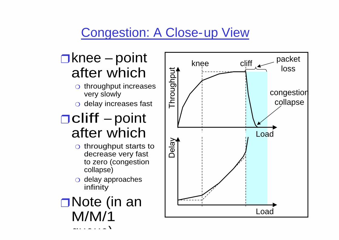
Congestion: A Close-up View
❒ knee – point after which
❍ throughput increases very slowly
❍ delay increases fast
❒cliff – point after which
❍ throughput starts to decrease very fast to zero (congestion collapse)
❍ delay approaches infinity
❒ Note (in an M/M/1 queue)
Load
Load
knee cliff
congestioncollapse
packetloss

Congestion Control vs. Congestion Avoidance
❒ Congestion control goal❍ stay left of cliff
❒ Congestion avoidance goal❍ stay left of knee
❒ Right of cliff: ❍ Congestion collapse
Load
knee cliff
congestioncollapse

Le contrôle de congestion: principes
❒ Réactif❍ lorsque la congestion est détectée, informer les noeuds en
amont et en aval,❍ puis, marquer des paquets, rejeter des paquets, traiter les
paquets prioritaires.❒ Préventif
❍ diffusion périodique d'informations d'états (taille des buffers)❍ contrôle continue de la source (Leacky Bucket, Token Bucket...),❍ contrôle de flux, contrôle d'admission.
❒ De bout en bout❍ pas de retour du réseau❍ la congestion est estimée grâce à l'observation des pertes et
des délais de bout-en-bout❒ Assisté par le réseau
❍ bit d'annonce de congestion (SNA, DECbit, TCP/ECN, FR, ATM)

Le contrôle de flux, pour le récepteur
❒ Fenêtrage❍ l'émetteur utilise une fenêtre d'anticipation dans laquelle
il va pouvoir envoyer une certaine quantité de données sans acquittements
❍ la taille de cette fenêtre peut être choisie par le récepteur à la phase de connexion
❍ si l'émetteur respecte les règles, le récepteur ne sera pas surchargé.
Cela ne garantit pas que le contrôle de flux sera efficace pour le réseau (voir figure suivante).

Pr oblème d’un r éseau t r op f aible

Le cont r ôle de f lux pour le r éseau
❒ Ex: principe du contrôle de congestion dans TCP❍ chaque émetteur maintient une deuxième fenêtre de
congestion pour le réseau,❍ la quantité d'information qu'il est autorisé à transmettre
par anticipation est le minimum des 2 fenêtres❍ initialement, la fenêtre de congestion est mise à K
octets, l'émetteur envoie les données et arme un temporisateur,
❍ si les données sont acquittées avant l'expiration du temporisateur, on augmente K, et ainsi de suite jusqu'à (i) l'expiration d'un temporisateur ou, (ii) la taille de la fenêtre du récepteur a été atteinte.
❍ C'est le principe du "slow start"

Slow Start
❒ La fenêtre de congestion augmente en fait très rapidement!
ACK for segment 1
segment 1cwnd = 1
cwnd = 2 segment 2segment 3
ACK for segments 2 + 3
cwnd = 4 segment 4segment 5segment 6segment 7
ACK for segments 4+5+6+7
cwnd = 8

Le cont r ôle de congest ion dans TCP
❒ seuil initial a 64K, on augmente K exponentiellement avant et linéairement après (congestion avoidance),
❒ si perte, divise le seuil par 2, et on recommence avec K=1

Ut ilisat ion du Round Tr ip Time
1
One RTT
One pkt time
0R
21R
3
42R
567
83R
91011
1213
1415
1
2 3
4 5 6 7

Slow Start Sequence Plot
Time
Sequence No
.
.
.
La fenêtre de congestion doubleà chaque aller/retour

TCP Reno (Jacobson 1990)
SStime
window
CA
SS: Slow StartCA: Congestion Avoidance Fast retransmission/fast recovery
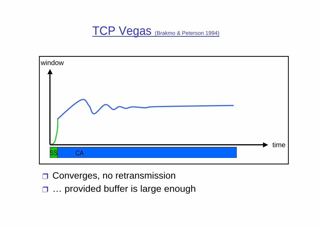
TCP Vegas (Brakmo & Peterson 1994)
SStime
window
CA
❒ Converges, no retransmission❒ … provided buffer is large enough

Queuing Disciplines
❒ Each router must implement some queuing discipline
❒ Queuing allocates bandwidth and buffer space:❍ Bandwidth: which packet to serve next (scheduling) ❍ Buffer space: which packet to drop next (buff mgmt)
❒ Queuing also affects latency
Class C
Class B
Class A
Traffic Classes
Traffic Sources
DropScheduling Buffer Management

Typical I nt er net Queuing
❒ FIFO + drop-tail❍ Simplest choice❍ Used widely in the Internet
❒ FIFO (first-in-first-out) ❍ Implies single class of traffic
❒ Drop-tail❍ Arriving packets get dropped when queue is full
regardless of flow or importance
❒ Important distinction:❍ FIFO: scheduling discipline❍ Drop-tail: drop (buffer management) policy

FIFO + Drop-tail Problems
❒ FIFO Issues: In a FIFO discipline, the service seen by a flow is convoluted with the arrivals of packets from all other flows!
❍ No isolation between flows: full burden on e2e control ❍ No policing: send more packets get more service
❒ Drop-tail issues:❍ Routers are forced to have have large queues to maintain high
utilizations❍ Larger buffers => larger steady state queues/delays❍ Synchronization: end hosts react to same events because
packets tend to be lost in bursts❍ Lock-out: a side effect of burstiness and synchronization is
that a few flows can monopolize queue space

Design Objectives
❒ Keep throughput high and delay low (i.e. knee)❒ Accommodate bursts❒ Queue size should reflect ability to accept bursts
rather than steady-state queuing❒ Improve TCP performance with minimal hardware
changes

Queue Management Ideas
❒ Synchronization, lock-out:❍ Random drop: drop a randomly chosen packet❍ Drop front: drop packet from head of queue
❒ High steady-state queuing vs burstiness:❍ Early drop: Drop packets before queue full❍ Do not drop packets “too early” because queue may
reflect only burstiness and not true overload
❒ Misbehaving vs Fragile flows:❍ Drop packets proportional to queue occupancy of flow❍ Try to protect fragile flows from packet loss (eg: color
them or classify them on the fly)
❒ Drop packets vs Mark packets:❍ Dropping packets interacts w/ reliability mechanisms❍ Mark packets: need to trust end-systems to respond!

Packet Drop Dimensions
AggregationPer-connection state Single class
Drop positionHead Tail
Random location
Class-based queuing
Early drop Overflow drop

Random Ear ly Det ect ion (RED)
Min threshMax thresh
Average Queue Length
minth maxth
maxP
1.0
Avg queue length
P(drop)

Random Ear ly Det ect ion (RED)
❒ Maintain running average of queue length❍ Low pass filtering
❒ If avg Q < minth do nothing❍ Low queuing, send packets through
❒ If avg Q > maxth, drop packet❍ Protection from misbehaving sources
❒ Else mark (or drop) packet in a manner proportional to queue length & bias to protect against synchronization
❍ Pb = maxp(avg - minth) / (maxth - minth)❍ Further, bias Pb by history of unmarked packets❍ Pa = Pb/(1 - count*Pb)

RED Issues
❒ Issues: ❍ Breaks synchronization well❍ Extremely sensitive to parameter settings❍ Wild queue oscillations upon load changes❍ Fail to prevent buffer overflow as #sources increases❍ Does not help fragile flows (eg: small window flows or
retransmitted packets)❍ Does not adequately isolate cooperative flows from non-
cooperative flows
❒ Isolation:❍ Fair queuing achieves isolation using per-flow state ❍ RED penalty box: Monitor history for packet drops,
identify flows that use disproportionate bandwidth

Variant: ARED (Feng, Kandlur, Saha, Shin 1999)
❒ Motivation: RED extremely sensitive to #sources and parameter settings
❒ Idea: adapt maxp to load❍ If avg. queue < minth, decrease maxp❍ If avg. queue > maxth, increase maxp
❒ No per-flow information needed

Variant: FRED (Ling & Morris 1997)
❒ Motivation: marking packets in proportion to flow rate is unfair (e.g., adaptive vs non-adaptive flows)
❒ Idea❍ A flow can buffer up to minq packets w/o being marked❍ A flow that frequently buffers more than maxq packets gets
penalized❍ All flows with backlogs in between are marked according to RED❍ No flow can buffer more than avgcq packets persistently
❒ Need per-active-flow accounting
Variant: BLUE (Feng, Kandlur, Saha, Shin 1999)
❒ Motivation: wild oscillation of RED leads to cyclic overflow & underutilization
❒ Algorithm❍ On buffer overflow, increment marking prob❍ On link idle, decrement marking prob

Var iant : St ochast ic Fair Blue
❒ Motivation: protection against non-adaptive flows ❒ Algorithm
❍ L hash functions map a packet to L bins (out of NxL )❍ Marking probability associated with each bin is
• Incremented if bin occupancy exceeds threshold• Decremented if bin occupancy is 0
❍ Packets marked with min {p1, …, pL}
1
1
1 1nonadaptive
adaptive
h1 hLhL-1h2
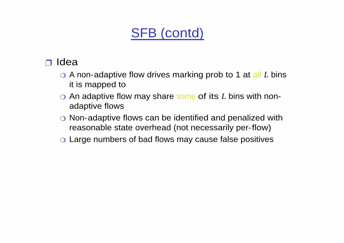
SFB (contd)
❒ Idea❍ A non-adaptive flow drives marking prob to 1 at all L bins
it is mapped to❍ An adaptive flow may share some of its L bins with non-
adaptive flows❍ Non-adaptive flows can be identified and penalized with
reasonable state overhead (not necessarily per-flow)❍ Large numbers of bad flows may cause false positives

0 2 4 6 8 1 0 1 2 1 4 1 6 1 8 2 00
0 . 1
0 . 2
0 . 3
0 . 4
0 . 5
0 . 6
0 . 7
0 . 8
0 . 9
1
L in k c o n g e s t io n m e a s u re
Lin
k m
ark
ing
pro
ba
bili
ty
REM Athuraliya & Low 2000
❒ Main ideas❍ Decouple congestion & performance measure❍ “Price” adjusted to match rate and clear buffer❍ Marking probability exponential in `price’
REM RED
Avg queue
1

Compar ison of AQM Per f or mance
DropTailqueue = 94%
REDmin_th = 10 pktsmax_th = 40 pktsmax_p = 0.1
REM
queue = 1.5 pktsutilization = 92%γ = 0.05, α = 0.4, φ = 1.15

QOS SPECI FI CATI ON, TRAFFIC, SERVICE
CHARACTERI ZATI ON, BASIC MECHANISMS

Service Specification
❒ Loss: probability that a flow’s packet is lost❒ Delay: time it takes a packet’s flow to get from
source to destination❒ Delay jitter: maximum difference between the
delays experienced by two packets of the flow❒ Bandwidth: maximum rate at which the soource
can send traffic❒ QoS spectrum:
Best Effort Leased Line

Har d Real Time: Guar ant eed Ser vices
❒ Service contract❍ Network to client: guarantee a deterministic upper bound
on delay for each packet in a session ❍ Client to network: the session does not send more than it
specifies
❒ Algorithm support❍ Admission control based on worst-case analysis❍ Per flow classification/scheduling at routers

Sof t Real Time: Cont r olled Load Service
❒ Service contract:❍ Network to client: similar performance as an unloaded
best-effort network❍ Client to network: the session does not send more than it
specifies
❒ Algorithm Support❍ Admission control based on measurement of aggregates❍ Scheduling for aggregate possible

Tr af f ic and Ser vice Char act er izat ion
❒ To quantify a service one has two know❍ Flow’s traffic arrival❍ Service provided by the router, i.e., resources reserved
at each router
❒ Examples:❍ Traffic characterization: token bucket❍ Service provided by router: fix rate and fix buffer space
• Characterized by a service model (service curve framework)

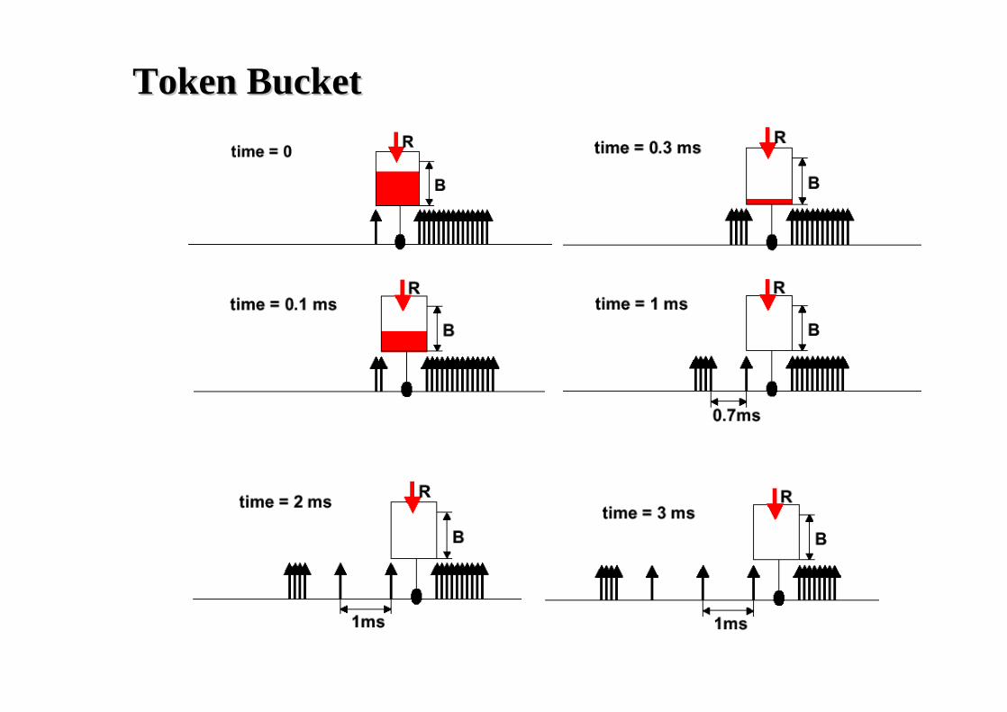
Ex: Token Bucket
❒ Characterized by three parameters (b, r, R)❍ b – token depth❍ r – average arrival rate❍ R – maximum arrival rate (e.g., R link capacity)
❒ A bit is transmitted only when there is an available token❍ When a bit is transmitted exactly one token is consumed
r tokens per second
b tokens
<= R bps
regulatortime
bits
b*R/(R-r)
slope R
slope r

Token BucketToken Bucket
Token BucketToken Bucket
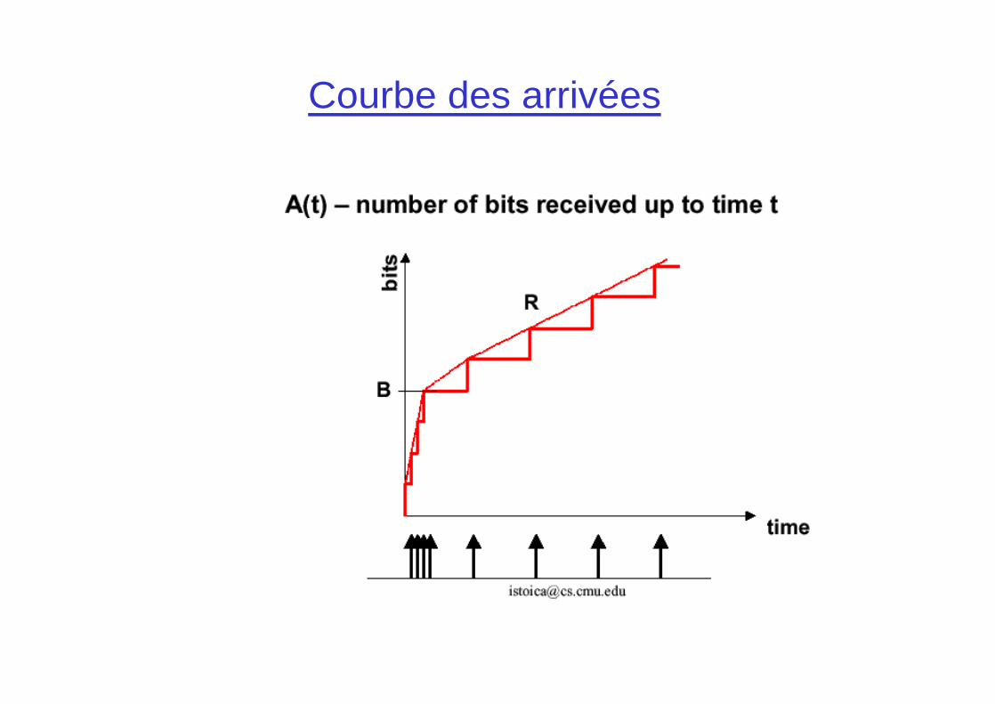
Courbe des arrivées

Token Bucket: Traffic Shaping/Policing
❒ Token bucket: limits input to specified Burst Size (b) and Average Rate (r).
❍ Traffic sent over any time T <= r*T + b❍ a.k.a Linear bounded arrival process (LBAP)
❒ Excess traffic may be queued, marked BLUE, or simply dropped

Tr af f ic Envelope (Ar r ival Cur ve)
❒ Maximum amount of service that a flow can send during an interval of time t
slope = max average rate
b(t) = Envelope
slope = peak rate
t
“Burstiness Constraint”

Char act er izing a Sour ce by Token Bucket
❒ Arrival curve – maximum amount of bits transmitted by time t
❒ Use token bucket to bound the arrival curve
time
bits
Arrival curve
time
bps

Example
❒ Arrival curve–maximum amount of bits transmitted by time t❒ Use token bucket to bound the arrival curve
size of timeinterval
bitsArrival curve
time
bps
0 1 2 3 4 5
1
2
1 2 3 4 5
1
2
3
4
(b=1,r=1,R=2)

Per-hop Reservation with Token Bucket
❒ Given b,r,R and per-hop delay d❒ Allocate bandwidth r a and buffer space Ba such
that to guarantee d
bits
b
slope rArrival curve
d
Ba
slope ra

What is a Ser vice Model?
❒ The QoS measures (delay,throughput, loss, cost) depend on offered traffic, and possibly other external processes.
❒ A service model attempts to characterize the relationship between offered traffic, delivered traffic, and possibly other external processes.
“external process”
Network elementoffered traffic
delivered traffic
(connection oriented)

Ar r ival and Depar t ur e Pr ocess
Network ElementRin Rout
Rin(t) = arrival process= amount of data arriving up to time t
Rout(t) = departure process= amount of data departing up to time t
bits
t
delay
buffer

Service Curve
❒ Assume a flow that is idle at time s and it is backlogged during the interval (s, t)
❒ Service curve: the minimum service received by the flow during the interval (s, t)

Big Picture
t t
slope = C
t
Rin(t)
Service curvebits bits
bits
Rout(t)

Delay and Buffer Bounds
t
S (t) = service curve
E(t) = Envelope
Maximum delay
Maximum buffer
bits

SCHEDULI NG

Packet Scheduling
❒ Decide when and what packet to send on output link
❍ Usually implemented at output interface
1
2
Scheduler
flow 1
flow 2
flow n
Classifier
Buffer management

Mechanisms: Queuing/ Scheduling
❒ Use a few bits in header to indicate which queue (class) a packet goes into (also branded as CoS)
❒ High $$ users classified into high priority queues, which also may be less populated
❍ => lower delay and low likelihood of packet drop
❒ Ideas: priority, round-robin, classification, aggregation, ...
Class C
Class B
Class A
Traffic Classes
Traffic Sources
$$$$$$
$$$
$

Scheduling And Policing Mechanisms
❒ Scheduling: choosing the next packet for transmission on a link can be done following a number of policies;
❒ FIFO: in order of arrival to the queue; packets that arrive to a full buffer are either discarded, or a discard policy is used to determine which packet to discard among the arrival and those already queued

Priority Queueing
❒ Priority Queuing: classes have different priorities; class may depend on explicit marking or other header info, eg IP source or destination, TCP Port numbers, etc.
❒ Transmit a packet from the highest priority class with a non-empty queue
❒ Preemptive and non-preemptive versions

Round Robin (RR)
❒ Round Robin: scan class queues serving one from each class that has a non-empty queue
one round

Weighted Round Robin (WRR)
❒ Assign a weight to each connection and serve a connection in proportion to its weight
❒ Ex:❍ Connection A, B and C with same packet size and weight
0.5, 0.75 and 1. How many packets from each connection should a round-robin server serve in each round?
❍ Answer: Normalize each weight so that they are all integers: we get 2, 3 and 4. Then in each round of service, the server serves 2 packets from A, 3 from B and 4 from C.
one round
w1
w2
wi

(Weighted) Round-Robin Discussion
❒ Advantages: protection among flows❍ Misbehaving flows will not affect the performance of
well-behaving flows• Misbehaving flow – a flow that does not implement any
congestion control
❍ FIFO does not have such a property
❒ Disadvantages:❍ More complex than FIFO: per flow queue/state❍ Biased toward large packets (not ATM)– a flow receives
service proportional to the number of packets
❒ If packet size are different, we normalize the weight by the packet size
❍ ex: 50, 500 & 1500 bytes with weight 0.5, 0.75 & 1.0

Gener alized Pr ocessor Shar ing (GPS)
❒ Assume a fluid model of traffic❍ Visit each non-empty queue in turn (like RR)❍ Serve infinitesimal from each❍ Leads to “max-min” fairness
❒ GPS is un-implementable!❍ We cannot serve infinitesimals, only packets
max-min fairness
Soit un ensemble de sources 1,..,n demandant des ressources x1,..,xn avec x1<x2..<xn par exemple. Le serveur a une capacité C.
On donne alors C/n à la source 1. Si C/n>x1, on donne C/n+(C/n-x1)/(n-1) aux (n-1) sourcesrestantes. Si cela est supérieur à x2, on recommence.(Existe en version max-min weighted faire share)

Gener alized Pr ocessor Shar ing
❒ A work conserving GPS is defined as
❒ where❍ wi – weight of flow i❍ Wi(t1, t2) – total service received by flow i during [t1, t2)❍ W(t1, t2) – total service allocated to all flows during [t1, t2)❍ B(t) – number of flows backlogged
)(),(),(
)(
tBiw
dtttW
w
dtttW
tBj ji
i ∈∀+=+ ∑ ∈

Fair Rat e Comput at ion in GPS
❒ Associate a weight wi with each flow i❒ If link congested, compute f such that
Cwfr ii
i =×∑ ),max(
8
6
244
2
f = 2: min(8, 2*3) = 6min(6, 2*1) = 2min(2, 2*1) = 2
10(w1 = 3)
(w2 = 1)
(w3 = 1)

Packet Appr oximat ion of Fluid Syst em
❒ GPS un-implementable❒ Standard techniques of approximating fluid GPS
❍ Select packet that finishes first in GPS assuming that there are no future arrivals (emulate GPS on the side)
❒ Important properties of GPS❍ Finishing order of packets currently in system
independent of future arrivals
❒ Implementation based on virtual time❍ Assign virtual finish time to each packet upon arrival❍ Packets served in increasing order of virtual times

Fair Queuing (FQ)
❒ Idea: serve packets in the order in which they would have finished transmission in the fluid flow system
❒ Mapping bit-by-bit schedule onto packet transmission schedule
❒ Transmit packet with the lowest finish time at any given time

FQ Simple Example
F=10
Flow 1(arriving)
Flow 2transmitting Output
F=2
F=5
F=8
Flow 1 Flow 2 Output
F=10
Cannot preempt packetcurrently being transmitted
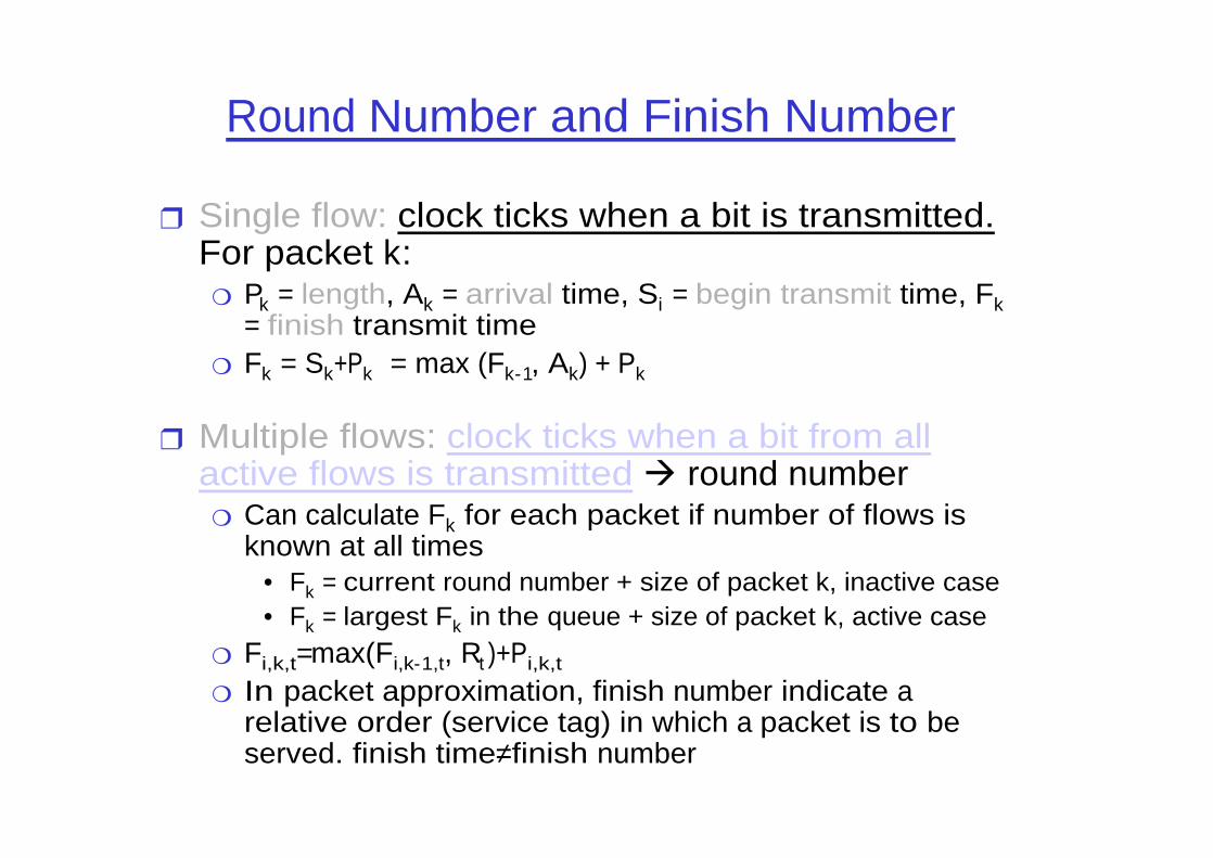
Round Number and Finish Number
❒ Single flow: clock ticks when a bit is transmitted.For packet k:
❍ Pk = length, Ak = arrival time, Si = begin transmit time, Fk= finish transmit time
❍ Fk = Sk+Pk = max (Fk-1, Ak) + Pk
❒ Multiple flows: clock ticks when a bit from all active flows is transmitted round number
❍ Can calculate Fk for each packet if number of flows is known at all times
• Fk = current round number + size of packet k, inactive case• Fk = largest Fk in the queue + size of packet k, active case
❍ Fi,k,t=max(Fi,k-1,t, Rt )+Pi,k,t
❍ In packet approximation, finish number indicate a relative order (service tag) in which a packet is to be served. finish time≠finish number

Example
❒ The round number increases at a rate inversely proportional to the number of active connections
❍ Thus is only used for computing finish numbers
❒ Largest finish number in a connection's queue is the connection's finish number
❒ Example❍ Suppose packets of size 1, 2 and 2 units arrive at a FQ
scheduler at time for connection A, B and C. Also, assume that a packet of size 2 arrive for connection A at time 4. The link service rate is 1 unit/s. Compute the finish number of all packets.
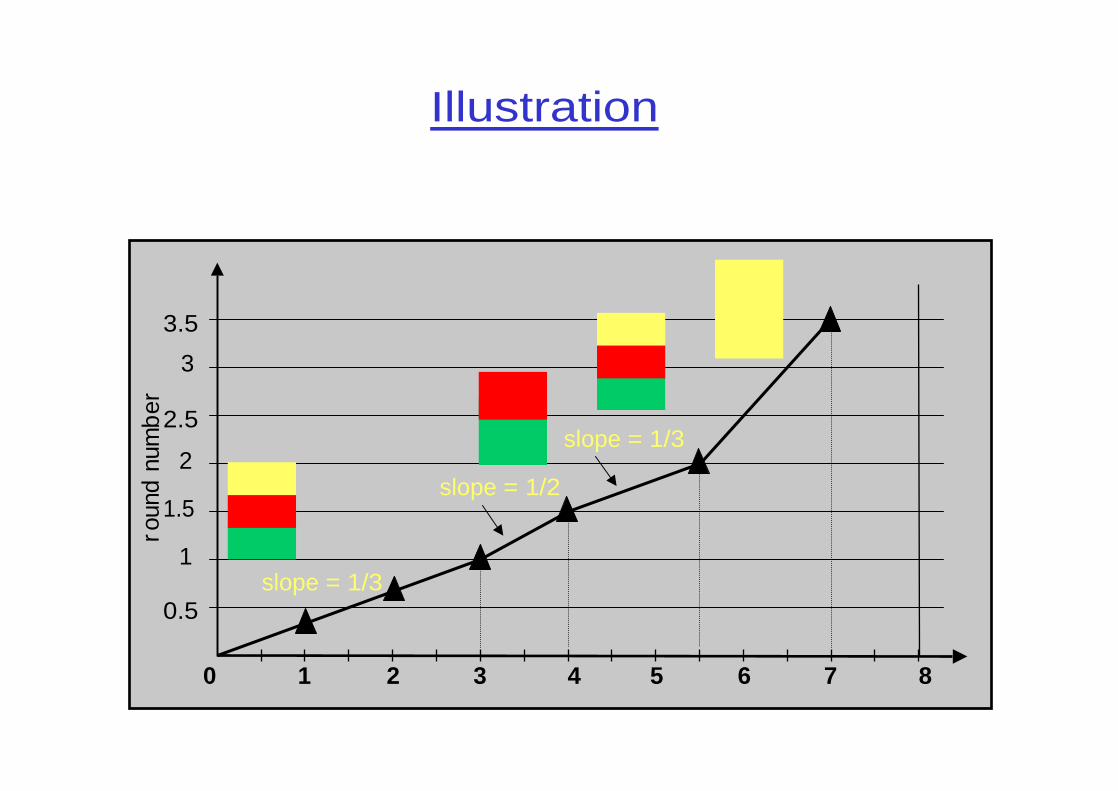
Illustration
0 2 64 8
roun
d nu
mb
er
0.5
1.5
2.5
3.5
1
2
3
slope = 1/3
slope = 1/2
slope = 1/3
1 3 5 7

FQ Advantages
❒ FQ protect well-behaved flows from ill-behaved flows
❒ Example: 1 UDP (10 Mbps) and 31 TCP’s shar ing a 10 Mbps link
FQ
0
0.2
0.4
0.6
0.8
1
1.2
1.4
1.6
1.8
2
1 4 7 10 13 16 19 22 25 28 31Flow Number
Th
rou
gh
pu
t(M
bp
s)RED
0
1
2
3
4
5
6
7
8
9
10
1 4 7 10 13 16 19 22 25 28 31Flow Number
Th
rou
gh
pu
t(M
bp
s)
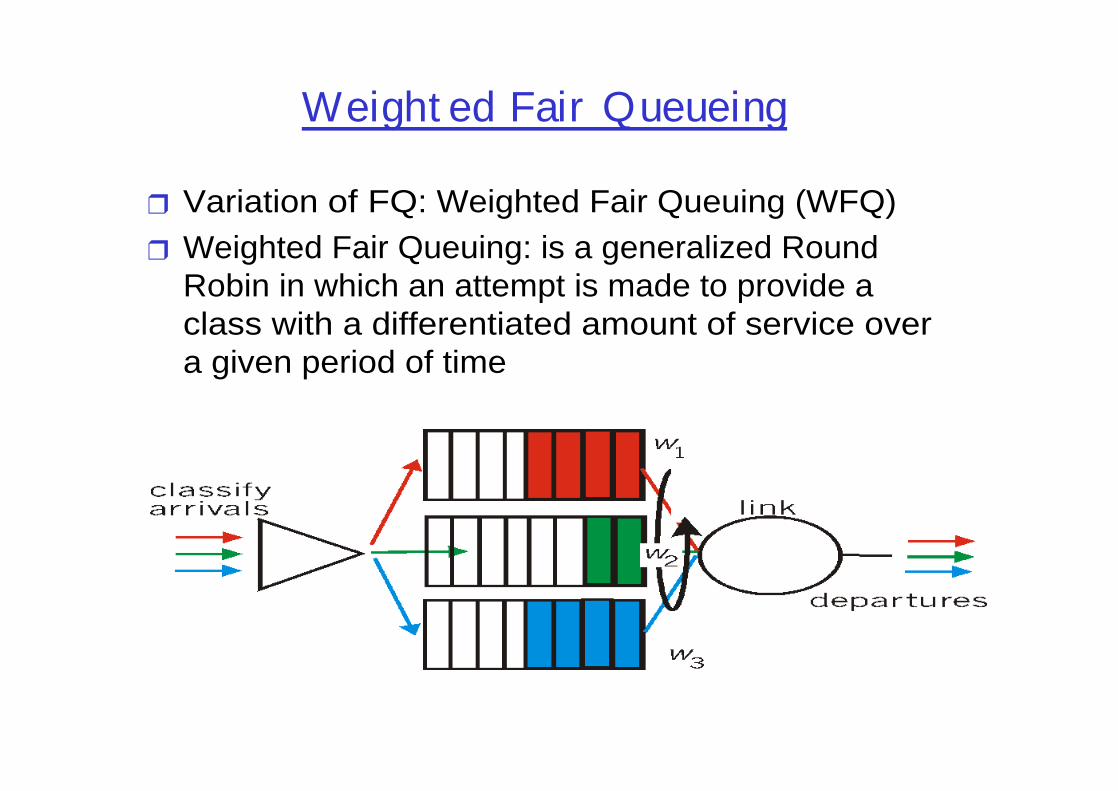
Weight ed Fair Queueing
❒ Variation of FQ: Weighted Fair Queuing (WFQ)❒ Weighted Fair Queuing: is a generalized Round
Robin in which an attempt is made to provide a class with a differentiated amount of service over a given period of time

Implementing WFQ
❒ WFQ needs per-connection (or per-aggregate) scheduler state→implementation complexity.
❍ complex iterated deletion algorithm❍ complex sorting at the output queue on the service tag
❒ WFQ needs to know the weight assigned for each queue →manual configuration, signalling.
❒ WFQ is not perfect…❒ Router manufacturers have implemented as early
as 1996 WFQ in their products❍ from CISCO 1600 series❍ Fore System ATM switches

Big Picture
❒ FQ does not eliminate congestion it just manages the congestion
❒ You need both end-host congestion control and router support for congestion control
❍ end-host congestion control to adapt❍ router congestion control to protect/isolate
❒ Don’t forget buffer management: you still need to drop in case of congestion. Which packet’s would you drop in FQ?
❍ one possibility: packet from the longest queue

Congestion control
(if not previously presented)

QoS ARCHITECTURES

Stateless vs. Stateful QoS Solutions
❒ Stateless solutions – routers maintain no fine grained state about traffic
scalable, robustweak services
❒ Stateful solutions – routers maintain per-flow state
powerful services• guaranteed services + high resource utilization• fine grained differentiation• protection
much less scalable and robust

Integrated Services (IntServ)❒ An architecture for providing QOS guarantees in IP networks
for individual application sessions❒ Relies on resource reservation, and routers need to maintain
state information of allocated resources (eg: g) and respond to new Call setup requests

I nt egr at ed Ser vices Model
❒ Flow specification❍ Leacky Bucket, Token Bucket
❒ Routing❒ Admission control❒ Policy control❒ Resource reservation
❍ RSVP
❒ Packet scheduling❍ WFQ, CBQ, RED

Integrated Services: Classes
❒ Guaranteed QOS: this class is provided with firm bounds on queuing delay at a router; envisioned for hard real-time applications that are highly sensitive to end-to-end delay expectation and variance
❒ Controlled Load: this class is provided a QOS closely approximating that provided by an unloaded router; envisioned for today’s IP network real-time applications which perform well in an unloaded network

Signaling semantics❒ Classic scheme: sender initiated❒ SETUP, SETUP_ACK, SETUP_RESPONSE❒ Admission control❒ Tentative resource reservation and confirmation❒ Simplex and duplex setup; no multicast support

RSVP for the IntServ approach
❒ Resource reSerVation Protocol❒ What is RSVP?
❍ Method for application to specify desired QoS to net❍ Switch state establishment protocol (signaling)❍ Multicast friendly, receiver-oriented❍ Simplex reservations (single direction)
❒ Why run RSVP?❍ Allows precise allocation of network resources❍ Guarantees on quality of service❍ Heterogeneous bandwidth support for multicast❍ Scalable (?)
source Gordon Schaffee

RSVP Design Cr it er ia
❒ Creates and maintains distributed reservation state
❒ Heterogeneous receivers (multicast)❍ Varying bandwidth needs
❒ Dynamic membership❒ Minimize control protocol overhead❒ Soft state in routers
❍ Reservations timeout if not refreshed periodically
❒ Adapt to routing changes gracefully: reestablish reservations
source Gordon Schaffee

Protocol Independence
❒ RSVP designed to work with any protocol❍ Protocol must provide QoS support❍ Examples: ATM, IP with Integrated Services
❒ Integrated Services❍ Defines different levels of packet delivery services❍ Defines method to communicate with applications:
Flowspec

Resource Reservation
❒ Senders advertise using PATH message❒ Receivers reserve using RESV message
❍ Flowspec + filterspec + policy data❍ Travels upstream in reverse direction of Path message
❒ Merging of reservations❒ Sender/receiver notified of changes

Call Admission
❒ Session must first declare its QOS requirement and characterize the traffic it will send through the network
❒ R- spec: defines the QOS being requested❒ T- spec: defines the traffic characteristics❒ A signaling protocol is needed to carry the R-spec
and T-spec to the routers where reservation is required; RSVP is a leading candidate for such signaling protocol
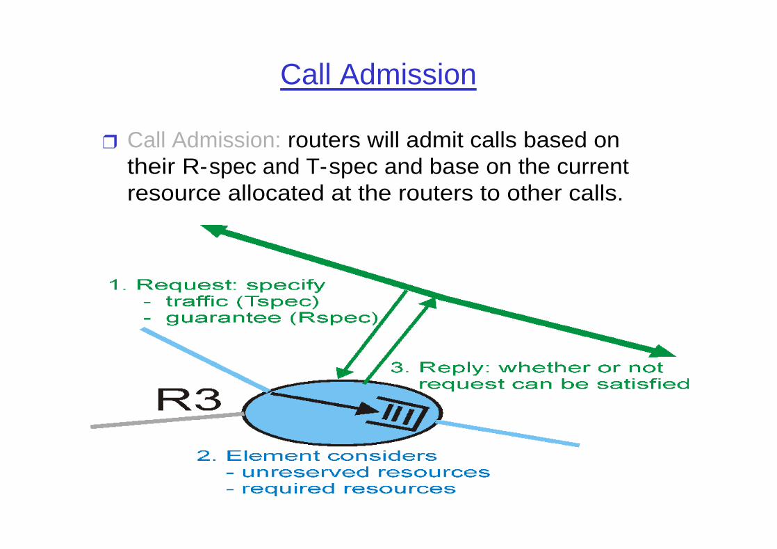
Call Admission
❒ Call Admission: routers will admit calls based on their R-spec and T-spec and base on the current resource allocated at the routers to other calls.

RSVP Funct ional Diagr am
Application
RSVPD
AdmissionsControl
PacketClassifier
PacketScheduler
PolicyControl
DATA
DATA
RSVPD
PolicyControl
AdmissionsControl
PacketClassifier
PacketScheduler
DATA
RoutingProcess
Host Router

Stateful Solution: Guaranteed Services
SenderReceiver
❒ Achieve per-flow bandwidth and delay guarantees❍ Example: guarantee 1MBps and < 100 ms delay to a flow

Stateful Solution: Guaranteed Services
SenderReceiver
❒ Allocate resources - perform per-flow admission control

Stateful Solution: Guaranteed Services
SenderReceiver
❒ Install per-flow state

SenderReceiver
❒ Challenge: maintain per-flow state consistent
Stateful Solution: Guaranteed Services

Stateful Solution: Guaranteed Services
SenderReceiver
❒ Per-flow classification

Stateful Solution: Guaranteed Services
SenderReceiver
❒ Per-flow buffer management

Stateful Solution: Guaranteed Services
SenderReceiver
• Per-flow scheduling

Stateful Solution Complexity
❒ Data path❍ Per-flow classification❍ Per-flow buffer
management❍ Per-flow scheduling
❒ Control path❍ install and maintain
per-flow state for data and control paths
Classifier
Buffermanagement
Scheduler
flow 1
flow 2
flow n
output interface
…
Per-flow State

Stateless vs. Stateful
❒ Stateless solutions are more❍ scalable❍ robust
❒ Stateful solutions provide more powerful and flexible services
❍ guaranteed services + high resource utilization❍ fine grained differentiation❍ protection

Question
❒ Can we achieve the best of two worlds, i.e., provide services implemented by stateful networks while maintaining advantages of stateless architectures?
❍ Yes, in some interesting cases. DPS, CSFQ.
❒ Can we provide reduced state services, I.e., maintain state only for larger granular flows rather than end-to-end flows?
❍ Yes: Diff-serv

DiffServ: Basic Ideas
❒ Differentiated services provide a way to specify the relative priority of packets
❒ Some data is more important than other data❒ People who pay for better service get it
Fujitsu Japan Fujitsu of America
Limited Bandwidth
The real question is to choose which packets shall be dropped. Thefirst definition of differential service is something like "not mine.” -- Christian Huitema
source Gordon Schaffee

Goals
❒ Ability to charge differently for different services
❒ Lightweight, scalable service discrimination suitable for network backbones
❍ No per flow state or per flow signaling
❒ Deploy incrementally, then evolve❍ Build simple system at first, expand if needed in future
❒ Make service separate from signaling
source Gordon Schaffee

Differentiated Services (DiffServ)
❒ Intended to address the following difficulties with Intserv and RSVP;
❒ Scalability: maintaining states by routers in high speed networks is difficult sue to the very large number of flows
❒ Flexible Service Models: Intserv has only two classes, want to provide more qualitative service classes; want to provide ‘relative’ service distinction (Platinum, Gold, Silver, …)
❒ Simpler signaling: (than RSVP) many applications and users may only w ant to specify a more qualitative notion of service

Architecture
❒ All policy decisions made at network boundaries❍ Boundary routers implement policy decisions by tagging
packets with appropriate priority tag❍ Traffic policing at network boundaries
❒ No policy decisions within network❍ Routers within network forward packets according to
their priority tags
source Gordon Schaffee

Dif f er ent iat ed Ser vices Model
❒ Edge routers: traffic conditioning (policing, marking, dropping), SLA negotiation
❍ Set values in DS-byte in IP header based upon negotiated service and observed traffic.
❒ Interior routers: traffic classification and forwarding (near stateless core!)
❍ Use DS-byte as index into forwarding table
IngressEdge Router
EgressEdge Router
Interior Router

Diffserv Architecture
Edge router:- per-flow traffic management
- marks packets as in-profile and out-profile
Core router:
- per class TM
- buffering and scheduling
based on marking at edge
- preference given to in-profile packets- Assured Forwarding
scheduling
...
r
b
marking

Scope of Service Class
❒ Packet priorities limited to an ISP❍ Extend with bilateral ISP agreements
❒ How can scope of priority be extended?❒ Differentiated services is unidirectional
Traffic marked for priority delivery
Traffic policed for profile violations
No marking of returning traffic
source Gordon Schaffee

Packet format support
❒ Packet is marked in the Type of Service (TOS) in IPv4, and Traffic Class in IPv6: renamed as “DS”
❒ 6 bits used for Differentiated Service Code Point (DSCP) and determine PHB that the packet will receive
❒ 2 bits are currently unused

Traffic Conditioning
❒ It may be desirable to limit traffic injection rate of some class; user declares traffic profile (eg, rate and burst size); traffic is metered and shaped if non-conforming

Per-hop Behavior (PHB)
❒ PHB: name for interior router data-plane functions❍ Includes scheduling, buff. mgmt, shaping etc
❒ Logical spec: PHB does not specify mechanisms to use to ensure performance behavior
❒ Examples: ❍ Class A gets x% of outgoing link bandwidth over time intervals
of a specified length❍ Class A packets leave first before packets from class B

PHB (contd)
❒ PHBs under consideration:❍ Expedited Forwarding (EF, premium): departure rate of
packets from a class equals or exceeds a specified rate (logical link with a minimum guaranteed rate)
• Emulates leased-line behavior
❍ Assured Forwarding (AF): 4 classes, each guaranteed a minimum amount of bandwidth and buffering; each with three drop preference partitions
• Emulates frame-relay behavior

Premium ServiceVan Jacobson (LBL)
❒ Conservative allocation of resources❍ Provisioned according to peak capacity profiles
❒ Shaped at boundaries to remove bursts❒ Out of profile packets dropped
❒ Defines a virtual leased line: fixed maximum bandwidth, but available when needed
source Gordon Schaffee
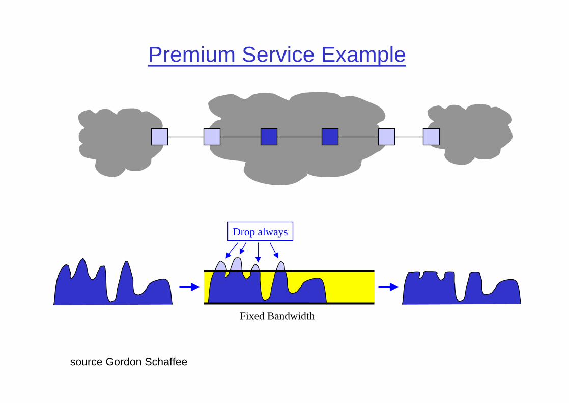
Premium Service Example
Fixed Bandwidth
Drop always
source Gordon Schaffee

AF PHB Gr oup (RFC 2597)
❒ Provides forwarding of IP packets in four independent service classes
❍ at each hop, each class has its own, configurable forwarding resources
❒ within each class, an IP packet is assigned one of three levels of drop precedence
❍ lower drop precedence means higher probability of forwarding
❒ forwarding resources (buffer space and bandwidth) can be allocated using
❍ FBA, CBQ, WFQ, priorities, etc.
❒ dropping of packets is based on the Random Early Drop (RED) algorithm
❍ each level of drop precedence (green, yellow, red) has its own RED threshold
source Juha Heinänen

Assur ed Ser vice Example
Assured Service
Drop if congested
Congested
Uncongested
source Gordon Schaffee

Example of Out put Behavior
RR
RR
RR
RR
RR
RR
Each AF class hasits own queue and
forwarding resources
Each AF class hasits own queue and
forwarding resources
RED thresholdfor “Red” packets
RED thresholdfor “Red” packets
RED thresholdfor “Yellow” packets
RED thresholdfor “Yellow” packets
source Juha Heinänen

RED wit h Mult iple Thr esholds
DiscardProbability
AverageQueue Length0
1
“Red”Threshold
0 “Yellow”Threshold
“Green”Threshold
“Red”Packets
“Red”Packets
“Green”Packets
“Green”Packets
“Yellow”Packets
“Yellow”Packets
Full
source Juha Heinänen

Summary
This document was created with Win2PDF available at http://www.daneprairie.com.The unregistered version of Win2PDF is for evaluation or non-commercial use only.


