
Qualification of innovative floating substructures for ... · API RP 2T, API RP 2SK API RP 2SK...
41
Qualification of innovative floating substructures for 10MW wind turbines and water depths greater than 50m Project acronym LIFES50+ Grant agreement 640741 Collaborative project Start date 2015-06-01 Duration 40 months Deliverable D7.1 Review of FOWT guidelines and design practice Lead Beneficiary DNV GL Due date 2015-09-01 Delivery date 2015-09-01 Dissemination level Public Status Final Classification Unrestricted Keywords Floating wind turbines, Standards, guidelines Company document number 1-XA7H9F The research leading to these results has received funding from the European Union Horizon2020 programme under the agreement H2020-LCE-2014-1-640741.
Transcript of Qualification of innovative floating substructures for ... · API RP 2T, API RP 2SK API RP 2SK...
Qualification of innovative floating substructures for
10MW wind turbines and water depths greater than 50m
Project acronym LIFES50+ Grant agreement 640741
Collaborative project Start date 2015-06-01 Duration 40 months
Deliverable D7.1 Review of FOWT guidelines and design practice
Lead Beneficiary DNV GL
Due date 2015-09-01
Delivery date 2015-09-01
Dissemination level Public
Status Final
Classification Unrestricted
Keywords Floating wind turbines, Standards, guidelines
Company document number 1-XA7H9F
The research leading to these results has received funding from the
European Union Horizon2020 programme under the agreement
H2020-LCE-2014-1-640741.
D7.1 Review of FOWT guidelines and design practice
LIFES50+ Deliverable, project 640741 2/41
Disclaimer
The content of the publication herein is the sole responsibility of the publishers and it does not neces-sarily represent the views expressed by the European Commission or its services.
While the information contained in the documents is believed to be accurate, the authors(s) or any other participant in the LIFES50+ consortium make no warranty of any kind with regard to this material including, but not limited to the implied warranties of merchantability and fitness for a particular pur-pose.
Neither the LIFES50+ Consortium nor any of its members, their officers, employees or agents shall be responsible or liable in negligence or otherwise howsoever in respect of any inaccuracy or omission herein.
Without derogating from the generality of the foregoing neither the LIFES50+ Consortium nor any of its members, their officers, employees or agents shall be liable for any direct or indirect or consequential loss or damage caused by or arising from any information advice or inaccuracy or omission herein.
Document information
Version Date Description
0.1 2015-07-22 Version for approval by AST
Prepared by Philipp Gujer, Kretschmer Matthias
Reviewed by Luca Vita
Approved by Kolja Mueller
1.0 2015-08-31 Final version for approval and submission to EC
Prepared by Philipp Gujer, Kretschmer Matthias
Reviewed by Jan Norbeck
Approved by Petter Andreas Berthelsen
Authors Organization
Philipp Gujer DNV GL
Kretschmer Matthias Stuttgart University
Contributors Organization
Luca Vita DNV GL
Kolja Mueller Stuttgart University
Frank Lemmer Stuttgart University
Denis Matha Stuttgart University
Knut O. Ronold DNV GL
Johan Slåtte DNV GL
D7.1 Review of FOWT guidelines and design practice
LIFES50+ Deliverable, project 640741 3/41
Definitions & Abbreviations
ABS
ALS
API
AST
American Bureau of Shipping
Accidental limit state
American Petroleum Institute
Administrative Support Team
BSH
Class NK
DDF
DDS
DFF
DLC
DNV GL
DTS
ECD
EDC
EOG
FLS
FSS
IEC
ISO
JIP
γf
γm
FOWT
LRFD
METI
MLIT
OWT
PC
Bundesamt für Schifffahrt und Hydrographie
Nippon Koiji Kyokai
Deep draught floaters
Deep draught semifloaters
Domain fatigue factor
Design Load Case
Det Norske Veritas - Germanischer Lloyds
Draft technical specifications
Extreme coherent gust with direction change
Extreme direction change
Extreme operating gust
Fatigue limit state
Floating substructure
International Electrotechnical Commission
International Organization of Standardization
Joint Industry Project
Load safety factor
Material factor
Floating offshore wind turbine
Load and resistance factor design method
Japanese Ministry of Economy, Trade and Industry
Japanese Ministry of Land, Infrastructure, Transport & Tourism
Offshore wind turbine
Project Coordinator
PM Project Manager
RP
RNA
SLS
SOLAS
TLP
ULS
WPL
WPS
Recommended practice
Rotor nacelle assembly
Serviceability limit state
Safety-of-Life-at-Sea
Tension leg platform
Ultimate limit state
Work Package Leader
Working stress design
D7.1 Review of FOWT guidelines and design practice
LIFES50+ Deliverable, project 640741 4/41
Executive Summary
The existing guidelines and standards addressing the design of floating offshore wind turbines
(FOWT) that are already published by classification societies, including DNV GL, ABS, and Class
NK, as well as the upcoming technical specification IEC 61400-3-2 are reviewed and differences will
be identified and documented. Furthermore, publically available design practices and publications
related to the FOWT design process are reviewed and documented to lay the groundwork for the
design practice development and to avoid any duplication of work already done
Contents
Introduction ..................................................................................................................................... 7 1
DNV-OS-J103:2013 Design of Floating Wind Turbine Structures ............................................... 8 2
2.1 DNV GL-SE-0073:2014 Project Certification of Wind Farms according to IEC 61400-22 ... 9
2.2 Technology qualification according to DNV-RP-A203:2013 ................................................. 9
Code Comparison, DNV-OS-J103:2013 vs. IEC-61400-3-2 (draft technical specification (DTS); 3
standard to be published) ....................................................................................................................... 10
3.1 Scope ..................................................................................................................................... 10
3.2 Design principles ................................................................................................................... 10
3.3 External conditions ................................................................................................................ 11
3.4 Loads ..................................................................................................................................... 12
3.5 Load and material factors ...................................................................................................... 13
3.6 Materials ................................................................................................................................ 14
3.7 Structural design .................................................................................................................... 14
3.8 Floating stability .................................................................................................................... 14
3.9 Station-keeping system .......................................................................................................... 14
3.10 Anchor system ....................................................................................................................... 15
3.11 Control system ....................................................................................................................... 15
3.12 Electrical and mechanical system .......................................................................................... 15
3.13 Corrosion protection system .................................................................................................. 15
3.14 Power cable design ................................................................................................................ 15
3.15 Assembly / transport / installation ......................................................................................... 15
3.16 Commissioning / maintenance / monitoring .......................................................................... 16
3.17 Other ...................................................................................................................................... 16
Code Comparison, DNV-OS-J103 :2013 vs. GL 2012-IV-2 ........................................................ 17 4
4.1 Scope ..................................................................................................................................... 17
4.2 Design principles ................................................................................................................... 17
4.3 External conditions ................................................................................................................ 17
4.4 Loads ..................................................................................................................................... 17
D7.1 Review of FOWT guidelines and design practice
LIFES50+ Deliverable, project 640741 5/41
4.5 Structural design .................................................................................................................... 18
4.6 Floating stability .................................................................................................................... 18
4.7 Station-keeping system .......................................................................................................... 19
4.8 Control system ....................................................................................................................... 19
4.9 Electrical and mechanical systems ........................................................................................ 19
4.10 Power cable design ................................................................................................................ 19
4.11 Corrosion protection system .................................................................................................. 20
4.12 Marine operations .................................................................................................................. 20
4.13 Inspection .............................................................................................................................. 20
Code Comparaison, DNV-OS-J103 :2013 vs. ABS #195 :2013 ................................................... 21 5
5.1 Scope ..................................................................................................................................... 21
5.2 General .................................................................................................................................. 21
5.3 Safety level ............................................................................................................................ 21
5.4 Environmental modelling ...................................................................................................... 21
5.5 Loads ..................................................................................................................................... 22
5.6 Structural design .................................................................................................................... 22
5.7 Station-keeping systems ........................................................................................................ 22
5.8 Floating stability .................................................................................................................... 23
5.9 Corrosion protection .............................................................................................................. 23
5.10 Control system ....................................................................................................................... 23
5.11 Miscellaneous ........................................................................................................................ 23
5.12 Conclusion ............................................................................................................................. 23
Code Comparison, DNV-OS-J103:2013 vs. Class NK:2012 ........................................................ 24 6
6.1 General .................................................................................................................................. 24
6.2 Scope ..................................................................................................................................... 24
6.3 Design principles ................................................................................................................... 24
6.4 Environmental modelling ...................................................................................................... 24
6.5 Loads ..................................................................................................................................... 25
6.6 Structural design .................................................................................................................... 25
6.7 Station-keeping system .......................................................................................................... 25
6.8 Floating stability .................................................................................................................... 26
6.9 Design of anchor system ....................................................................................................... 27
6.10 Corrosion protection .............................................................................................................. 27
Other Standards to be used ............................................................................................................ 28 7
7.1 DNV GL Standards ............................................................................................................... 28
7.2 IEC Standards ........................................................................................................................ 32
D7.1 Review of FOWT guidelines and design practice
LIFES50+ Deliverable, project 640741 6/41
7.3 ISO Standards ........................................................................................................................ 33
7.4 API Standards and others ...................................................................................................... 34
7.5 National requirements ........................................................................................................... 35
Other Relevant References ............................................................................................................ 36 8
8.1 Results from research projects............................................................................................... 36
Conclusion ..................................................................................................................................... 39 9
Bibliography .................................................................................................................................. 40 10
D7.1 Review of FOWT guidelines and design practice
LIFES50+ Deliverable, project 640741 7/41
Introduction 1
The four designers involved in LIFES50+ have agreed to use the DNV-OS-J103, Design of Floating
Wind Turbine Structures, as main reference standard for the design of their concepts.
It is assumed that the IEC certification scheme is followed, as described in DNVGL-SE-0073.
This report includes a brief description of the requirements included in DNV-OS-J103 and a
comparison with some of the other standards available in the market. The following standards and
guidelines will be compared to DNV-OS-J103:
IEC 61400-3-2, Design requirements for floating offshore wind turbines (draft technical
specification (DTS); standard to be published);
GL Guideline IV-2, Guideline for the Certification of Offshore Wind Turbines, edition 2012;
ABS Guideline #195, Guide for Building and Classing Floating Offshore Wind Turbine
Installations, January 2013;
Class NK, Guidelines for Offshore Floating Wind Turbine Structures, July 2012.
The guidelines will be compared guideline by guideline and topic by topic. The focus of this
comparison is on technical requirements, not on certification services. The references to be used in
combination with above mentioned standards and guidelines are also listed, e.g. DNV GL, ISO, API,
etc.
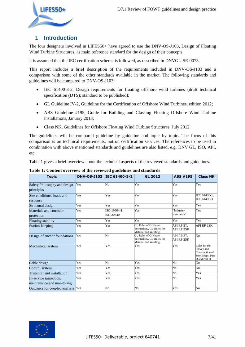
Table 1 gives a brief overview about the technical aspects of the reviewed standards and guidelines.
Table 1: Content overview of the reviewed guidelines and standards
Topic
DNV-OS-J103 IEC 61400-3-2 GL 2012 ABS #195 Class NK
Safety Philosophy and design
principles
Yes No Yes Yes Yes
Site conditions, loads and
response
Yes Yes Yes Yes IEC 61400-1, IEC 61400-3
Structural design Yes Yes Yes Yes Yes
Materials and corrosion
protection
Yes ISO 19904-1,
ISO 20340
Yes “Industry standards”
Yes
Floating stability Yes Yes Yes Yes Yes
Station-keeping Yes Yes GL Rules of Offshore
Technology, GL Rules for
Material and Welding
API RP 2T,
API RP 2SK
API RP 2SK
Design of anchor foundations Yes No GL Rules of Offshore
Technology, GL Rules for
Material and Welding
API RP 2T,
API RP 2SK
No
Mechanical system
Yes Yes Yes Yes Rules for the
Survey and
Construction of
Steel Ships: Part
D and Part H
Cable design Yes No Yes No No
Control system Yes Yes Yes No No
Transport and installation Yes Yes Yes No Yes
In-service inspection,
maintenance and monitoring
Yes Yes Yes No Yes
Guidance for coupled analysis Yes No No Yes No
D7.1 Review of FOWT guidelines and design practice
LIFES50+ Deliverable, project 640741 8/41
DNV-OS-J103:2013 2
Design of Floating Wind Turbine Structures
DNV-OS-J103 has been developed on a JIP with industry involvement. This involvement included
participation by 3 developers, and full scale data and analysis data for their respective floater concepts
were used in the development. DNV-OS-J103 needs to be applied in combination with DNV-OS-J101
and DNV-RP-C205.
Structural safety is ensured by the use of a safety class methodology where the structure to be designed
is classified into a safety class based on failure consequences. This classification is normally
determined based on the purpose of the structure. For each safety class, a target safety level can be
defined in terms of an annual probability of failure. The safety classes are considering the structural
design of the floating wind turbine structure and its station-keeping system.
Three safety classes are defined:
low safety class (annual probability of failure of 10-3
): low risk of human injury, minor
environmental consequences, minor economic consequences and negligible risk to human life;
normal safety class (annual probability of failure of 10-4
): imply some risk for human injury,
some risk for environmental pollution or significant economic consequences;
high safety class (annual probability of failure of 10-5
): failures imply large possibilities for
human injuries or fatalities, for significant environmental pollution or major societal losses or
very large economic consequences.
The different safety classes applicable for different parts of the floating units and their station-keeping
systems are reflected in terms of different requirements for load factors. The requirements for material
factors remain unchanged regardless of which safety class is applicable for a particular wind farm or
structure in question. The DNV-OS-J103 is based on the partial safety factor method, which is based
on separate assessments of the load effect in the structure due to each applied load process. The partial
safety factor method is a design method by which the target safety level is obtained as closely as
possible by applying load and resistance factors to characteristic values of the governing variables and
subsequently fulfilling a specified design criterion expressed in terms of these factors and these
characteristic values. The characteristic values of loads and resistance, or of load effects and material
strengths are chosen as specific quantiles in their respective probability distributions. The requirements
for the load and resistance factors are set such that possible unfavourable realisations of loads and
resistance, as well as their possible simultaneous occurrences, are accounted for to an extent which
ensures that a satisfactory safety level is achieved.
For the structural design DNV-OS-J103 requires design against limit states. While most renewables
standards require design against ULS (ultimate limit state), FLS (fatigue limit state) and SLS
(serviceability limit state), DNV-OS-J103 requires design against ALS (accidental limit state) as well.
ALS defined by DNV-OS-J103 covers:
structural damage or failure caused by accidental loads;
maintain structural integrity after local damage or flooding;
post-accident resistance of the structure against environmental loads when the structural
resistance has become reduced by structural damage caused by the design accidental loads
such as the design fire or the design collision.
D7.1 Review of FOWT guidelines and design practice
LIFES50+ Deliverable, project 640741 9/41
DNV-OS-J103 has a requirement for a floater motion control system to minimize excitation of floater
motions.
DNV-OS-J103 allows sinking of FOWT by considering damaged stability as an optional requirement.
Detailed guidance about load analysis of FOWT is provided in the appendix of DNV-OS-J103.
2.1 DNV GL-SE-0073:2014 Project Certification of Wind Farms according to IEC 61400-22
DNV GL-SE-0073 service specification specifies DNV GL’s services for project certification of
onshore and offshore wind farms according to IEC 61400-22. It includes DNV GL’s interpretation and
detailing of IEC 61400-22 to serve as a contractual basis for project certification. Furthermore it
provides a common communication platform for describing the scope and extent of activities
performed for project certification of a wind farm and its assets.
DNV GL’s project certification system details and clarifies the verification activities within IEC
61400-22 system and utilises DNV GL standards to fill gaps in the governing IEC standards.
The project certification concept for wind farms constitutes a robust means to provide, through
independent verification, evidence to stakeholders (financiers, partners, utility companies, insurance
companies, the public, governmental and non-governmental organisations) that a set of requirements
laid down in standards are met during design and construction, and maintained during operation of a
wind farm.
DNV GL-SE-0073 also describes how to maintain this certificate by periodic maintenance during the
service life of the wind farm.
2.2 Technology qualification according to DNV-RP-A203:2013
Components and concepts that cannot be verified against any standard are considered a new
technology. In this case a risk based approach can be used for the verification, as described in DNV-
RP-A203, Recommended Practice for Technology Qualification.
Technology qualification is the process of providing the evidence that a technology will function
within specified operational limits with an acceptable level of confidence.
The objective of the DNV-RP-A203 is to provide the industry with a systematic approach to
technology qualification, ensuring that the technology functions reliably within specified limits.
The approach is applicable for components, equipment and systems, which are not already covered by
a validated set of requirements (such as an applicable standard).
The result of the qualification is documentation of evidence that the technology meets the specified
requirements for the intended use, implying:
the probability density distribution for the service lifetime is determined and/or,
the reliability is determined and/or
sufficient margins are defined against specified failure modes or towards specified
performance targets.

D7.1 Review of FOWT guidelines and design practice
LIFES50+ Deliverable, project 640741 10/41
Code Comparison, DNV-OS-J103:2013 vs. IEC-61400-3-2 (draft 3
technical specification (DTS); standard to be published)
3.1 Scope
IEC 61400-3-2 focusses on engineering integrity of structural components. Subsystems are addressed,
namely control and protection mechanisms, internal electrical systems and mechanical systems. IEC
61400-3-2 can be seen as an extension of IEC 61400-1 and -3, which apply except where noted. Thus,
IEC 61400-3-2 is consistent with IEC 61400-1 and IEC 61400-3. Explicit exceptions with regard to
differences from fixed bottom offshore wind turbines are highlighted in IEC 61400-3-2.
IEC 61400-3-2 includes design of the RNA, tower and support structure as well as the station keeping
systems. Substructures considered explicitly are Ship-based structures and barges, Semi-submersibles,
Spar buoys and Tension-leg platforms. Floating structures have to be unmanned and equipped with
only one single horizontal axis wind turbine.
Other platforms intended to support wind turbines are generally but not fully covered due to the great
range of variability in geometry and structural form. For the design of multi-turbine units, vertical-axis
wind turbines and combined wind/wave energy systems additional consideration are deemed necessary.
The major difference to the scope DNV-OS-J103 is the inclusion of the RNA, which is explicitly not
included in the scope of the DNV guideline but instead reference is given to DNV-DS-J102.
Compared to IEC 61400-3-2, DNV-OS-J103 provides explicit chapters referring to Safety Philosophy
and design principles, Materials and corrosion protection, Design of anchor foundations, Cable design
and Guidance for coupled analysis, but misses chapters on tropical storms, tsunamis and load
extrapolation. These topics are commonly addressed in the other guideline respectively, but generally
not in the same level of detail.
3.2 Design principles
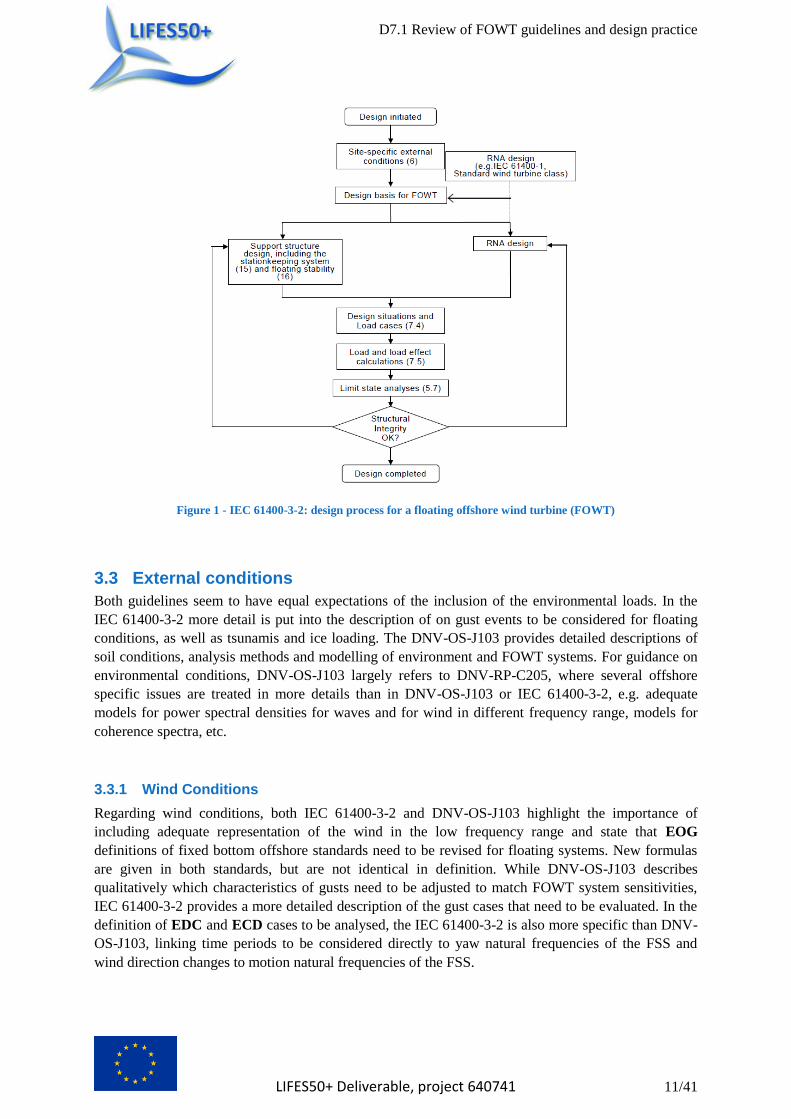
IEC 61400-3-2 provides a workflow of the design methodology that is based on the methodology
provided in IEC 61400-3-1, but extended through inclusion of the design of the station keeping system
and the consideration of floating stability. Demonstration of structural integrity of the RNA with
respect to site specific conditions is also required. The possible influence of the increased dynamic
response of FOWT systems on the control and safety system is also mentioned.
For Design principles both DNV-OS-J103 and IEC 61400-3-2 generally use the design by partial
safety factor method. IEC 61400-3-2 additionally allows the use of the working stress design (WSD).
DNV-OS-J103 also presents possibilities for design assisted by testing and probability-based design.
Another fundamental difference is the mandatory inclusion of model tests in the DNV-OS-J103 to
validate the numerical model. DNV-OS-J103 refers to the section 10 of DNV-RP-C205 for guidance
on the setup of the model test.
D7.1 Review of FOWT guidelines and design practice
LIFES50+ Deliverable, project 640741 11/41
Figure 1 - IEC 61400-3-2: design process for a floating offshore wind turbine (FOWT)
3.3 External conditions
Both guidelines seem to have equal expectations of the inclusion of the environmental loads. In the
IEC 61400-3-2 more detail is put into the description of on gust events to be considered for floating
conditions, as well as tsunamis and ice loading. The DNV-OS-J103 provides detailed descriptions of
soil conditions, analysis methods and modelling of environment and FOWT systems. For guidance on
environmental conditions, DNV-OS-J103 largely refers to DNV-RP-C205, where several offshore
specific issues are treated in more details than in DNV-OS-J103 or IEC 61400-3-2, e.g. adequate
models for power spectral densities for waves and for wind in different frequency range, models for
coherence spectra, etc.
3.3.1 Wind Conditions
Regarding wind conditions, both IEC 61400-3-2 and DNV-OS-J103 highlight the importance of
including adequate representation of the wind in the low frequency range and state that EOG
definitions of fixed bottom offshore standards need to be revised for floating systems. New formulas
are given in both standards, but are not identical in definition. While DNV-OS-J103 describes
qualitatively which characteristics of gusts need to be adjusted to match FOWT system sensitivities,
IEC 61400-3-2 provides a more detailed description of the gust cases that need to be evaluated. In the
definition of EDC and ECD cases to be analysed, the IEC 61400-3-2 is also more specific than DNV-
OS-J103, linking time periods to be considered directly to yaw natural frequencies of the FSS and
wind direction changes to motion natural frequencies of the FSS.
D7.1 Review of FOWT guidelines and design practice
LIFES50+ Deliverable, project 640741 12/41
3.3.2 Marine Conditions
3.3.2.1 Waves
Both guidelines highlight the need to regard wind and waves as independent parameters and to include
the influence of swell spectra additionally to known wave spectra from fixed bottom offshore
structures. IEC 61400-3-2 refers to ISO 19901-1 for swell spectra. DNV-OS-J103 claims that the use
of JONSWAP or other one peaked wave spectra is insufficient for FOWT in the presence of swell and
two-peaked power spectrums are recommended. Considering the 50-year wave height, DNV-OS-J103
suggests that the factor to be multiplied with the 50 year significant wave height used in the IEC
61400-3-1 is non conservative and proposes values of up to 2.0 in deep waters.
3.3.2.2 Current
In general no discrepancies were found. IEC 61400-3-2 generally demands a revision of load impact
of wind, wave and current misalignment in all load cases in IEC 61400-3-1. Regarding vortex effects,
reference is made to ISO 19904-1, ABS and DNV-OS-J103
3.3.3 Further External Conditions
Regarding the water level, while DNV-OS-J103 simply asks for the inclusion of high and low water
levels, IEC 61400-3 demands to take into account a variation of water levels if they are significant.
For the soil conditions, both guidelines demand establishment of soil conditions for each site.
Additionally DNV-OS-J103 provides a table of typical ranges of soil parameters for cohesion less and
cohesive soils. In DNV-OS-J103 also the effect of cyclic loading on soil conditions is addressed and
consideration demanded.
With regard to marine growth, IEC 61400-3-2 specifically asks for the evaluation of the effect on the
range of Eigen frequencies, while DNV-OS-J103 demands consideration of all effects on weight and
dimensions.
The effect of earthquakes and tsunamis is covered with varying depth. While DNV-OS-J103 states
that the size of tsunami waves is dependent on the water depth and may be very small. Only the
influence for tension leg platforms (the same is expected to be true for taut mooring systems) is
mentioned. There, the effects on the station keeping system design should be assessed.
IEC 61400-3-2 provides a detailed Annex on the modelling of tsunamis, and also refers to ISO 19900,
ISO 19901-2, ISO 19901-4 and ISO 19904-1 for soil properties during earthquakes, while stating that
only tension and taut mooring systems could be influenced. Additionally, the phase of forcing at
separate anchor points is asked to be considered.
3.4 Loads
Loads and load effects chapters are organized different than in DNV-OS-J103. Effects to be
considered regarding gravitational and inertial loads, aerodynamic loads, hydrodynamic loads, loads
through wake situations, line interaction and hydrostatic effects are generally the same. The complex
interaction of FOWT with their environment demand the consideration of various new effects
compared to fixed bottom turbines which are mentioned in both guidelines.
Looking at hydrodynamic loads, the air gap is to be considered by both DNV-OS-J103 and IEC
61400-3-2. Additionally, IEC 61400-3-2 contains requirements concerning the evaluation of air gap,
i.e. more detailed inclusion of model tests and wave run-up.
The calculation of the impact of tsunamis is explained in detail in the annex of IEC 61400-3-2. Also
IEC 61400-3-2 marks the consideration of a tsunami warning system in order to exclude additional
D7.1 Review of FOWT guidelines and design practice
LIFES50+ Deliverable, project 640741 13/41
loading from the operating turbine. DNV-OS-J103 notes the influence of the water depth on the crest
height of tsunamis.
Ice loads are considered with regard to ISO 19906 in the IEC 61400-3-2, while IEC 61400-3-1
assumptions are not regarded as applicable to FOWT. Additionally to ISO 19906 loads, in the IEC
61400-3-2 ice loads shall be considered in combination with movement due to loads from ice, wind,
wave or currents as well as ice loads on electrical cables. IEC 61400-3-2 also allows the usage of ice
management systems to reduce ice loading. In contrast, the DNV-OS-J103 refers to DNV-OS-J101
and additionally requires consideration of drifting ice impact, if applicable.
Additional Design load cases are defined in IEC 61400-3-2, extending the table given in IEC 61400-
3-1. Special consideration is mentioned towards misalignment of wind, wave, swell and current that
need to be included if higher loading is to be expected. Faults of active control systems of the support
structure shall be considered in fault conditions. In contrast, DNV-OS-J103 adds multiple chapters to
the load cases defined in DNV-OS-J101 which are referred to as environmental loads. These load
chapters describe qualitatively the supplement load cases to be considered which are called permanent
loads, variable functional loads, abnormal wind turbine loads (loads associated with fault situations for
the wind turbine), deformation loads and accidental loads. The load case table from DNV-OS-J101 as
mentioned in the chapter environmental loads is highlighting the importance of gust loads on FOWT
systems that use control system for stability. Wind and wave misalignment are only to be considered
as part of the ULS load cases with the most unfavourable direction of wind and waves.
The simulation length is discussed in both guidelines with comparable detail. IEC 61400-3-2
provides a detailed description about simulation length and binning and states the need for longer
simulation lengths for adequate representation of the hydrodynamic frequency range as well as the
possibility to use periodic wind data in order to mitigate the problem of stationarity assumption of the
wind field. Likewise, DNV-OS-J103 proposes longer simulation times to capture hydrodynamic
effects and offers various solutions to the stationarity assumption problem of the wind field.
Modelling requirements are in general the same for both guidelines but described more detailed in
DNV-OS-J103. With regard to aerodynamics loads, the IEC 61400-3-2 highlights the possible
deficiency of Stream-tube-based induction models for FOWT. Considering hydrodynamic loads, IEC
61400-3-2 provides a list of relevant models for various phenomena, but also refers to ISO 19904-1,
ABS, Class NK and DNV-OS-J103, where a detailed Appendix on system analysis and the modelling
of various FOWT systems is given. Furthermore DNV-OS-J103 refers to DNV-RP-C205, where more
detailed guidance is given on specific topics, e.g. vortex-induced vibrations and vortex-induced
motions, determination hydrodynamic coefficients, higher order sum-frequency forces that may
introduce springing and/or ringing response in vertical modes, wave slamming and its representation,
estimation of hydrodynamic load on power cables subjected to accumulated marine growth, etc.
3.5 Load and material factors
IEC 61400-3-2 allows both the use of partial safety factors that is already applied in IEC 61400-1 as
well as the working stress method (WSD) as used in ISO 19904-1. While IEC 61400-3-2 differs only
between load favourability and type of design situation with respect to the partial safety factors, DNV-
OS-J103 looks at different load factor sets, load categories, and safety classes.
Overall, IEC 61400-3-2 and DNV-OS-J103 both use 0.9 as the most optimistic value. While DNV-
OS-J103’s most pessimistic value is 1.55 and IEC 61400-3-2’s only 1.5, there is a larger variety of less
conservative values applied in DNV-OS-J103. A comparison between the two methods is thus not
D7.1 Review of FOWT guidelines and design practice
LIFES50+ Deliverable, project 640741 14/41
trivial but has been tried before (Using Partial Safety Factors in Wind Turbine Design and Testing
(WD Musial - 1997))
Regarding fatigue failure in the IEC 61400-3-2 and DNV-OS-J103, partial safety factors are set to
unity for both guidelines.
Material factors and resistances are not treated in IEC 61400-3-2. Instead reference is made to ISO
structural and other recognized offshore design standards.
3.6 Materials
IEC 61400-3-2 refers only to the ISO 19901-7 and ISO 19904-1 and doesn’t give any further
information. Generally in DNV-OS-J103 the material selection shall be undertaken in accordance with
the principles given in DNV-OS-J101. In addition some further guidelines for the use of different
materials in FOWT (concrete, steel, etc.) and links to other standards are given.
3.7 Structural design
For the design methodology, see chapter 4.5.
The IEC 61400-3-2 provides a lot of requirements regarding loads and load calculations under the
topic “structural design” which is already processed in chapter 4.4 loads.
For the Ultimate limit state analysis in IEC 61400-3-2 there is sensitivity against fatigue failure and
the method of counting unclosed cycles respectively. So it is recommended to use concatenated
simulation data sets to minimize this sensitivity. Furthermore in IEC 61400-3-2 a serviceability
analysis has to be performed in the course of the ULS analysis, in which the designer shall propose
appropriate limiting values to ensure the integrity and serviceability of the FOWT and related
infrastructure.
3.8 Floating stability
In general IEC 61400-3-2 refers to the IMO intact stability code, Resolution MSC.267(85). In DNV-
OS-J103 a lot of stability requirements are explicitly given for different types of FOWT. However in
IEC 61400-3-2 alternative intact stability criteria based on dynamic-response can be used, which is not
mentioned in DNV-OS-J103. Both standards don’t see damaged stability as a requirement for
unmanned units, but IEC 61400-3-2 states explicitly, that it has to be proven that no other
neighbouring facilities are damaged.
3.9 Station keeping system
Basically IEC 61400-3-2 references to the ISO 19901-7 standard. In the case of non-redundant station
keeping systems, an increase in safety factors are to be considered according to IEC 61400-3-2 and
DNV-OS-J103 as well.
D7.1 Review of FOWT guidelines and design practice
LIFES50+ Deliverable, project 640741 15/41
3.10 Anchor system
The IEC 61400-3-2 is referencing the ISO 19901-4, ISO 19901-7 and DNV-OS-J103 standards and
gives no further requirements.
3.11 Control system
Both standards refer to IEC 61400-1 and IEC 61400-3 for the control and protection system of the
wind turbine itself. In both standards the resonance and dynamic amplification of motions due to
control system actions shall be avoided. In addition to the IEC 61400-1 standard the IEC 61400-3-2
demands the activation of the protection system in the following events:
failure of the control function of the floating support structure
motions and accelerations of the floating sub-structure exceed operational limits
tower inclination angle exceeds operational limits
3.12 Electrical and mechanical system
For the electrical system IEC 61400-3-2 refers to the relevant IEC or RCS rules without exactly
specifying them. DNV-OS-J103 considers only the lightning and earthing system with referencing to
the related standards.
Regarding the mechanical system both standards state that the larger motion of a FOWT and its
influence on the design, wear, and lubrication of the mechanical systems shall be taken into account.
3.13 Corrosion protection system
IEC 61400-3-2 refers to ISO 19904-1 and ISO 20340 for guidance regarding corrosion protection
systems and how these are accounted for in the design.
Generally the DNV-OS-J103 standard refers to DNV-OS-J101, but additionally floater specific
requirements are provided.
3.14 Power cable design
While a big chapter in DNV-OS-J103 is dedicated to the power cable design, where criteria,
requirements and guidance for structural design and analysis of power cable systems are given, the
IEC 61400-3-2 and 61400-3 as well don’t mention this topic.
3.15 Assembly / transport / installation
The IEC 61400-3-2 references here ISO 19901-6 and IEC 61400-3-1. DNV-OS-J103 refers to DNV-
OS-J101. In addition both standards basically mention that the stability and structural integrity of the
FOWT during assembly, transportation and installation operations should be verified.
D7.1 Review of FOWT guidelines and design practice
LIFES50+ Deliverable, project 640741 16/41
3.16 Commissioning / maintenance / monitoring
For operation and maintenance of FOWT the IEC 61400-3-2 points to the ISO 19901-6; in DNV-OS-
J103 the DNV-OS-J101 is referenced. While commissioning is considered in IEC 61400-3-2 and some
requirements are given, the DNV-OS-J103 doesn’t mention this topic. In addition to DNV-OS-J103
the IEC 61400-3-2 provides information about an emergency procedures plan.
3.17 Other
Marine Support Systems: In the IEC 61400-3-2 a small chapter is dedicated to the marine support
systems, which includes the bilge- and ballast system; both systems are considered in the mechanical
systems chapter in DNV-OS-J103 with a reference to the DNV-OS-D101 standard.
D7.1 Review of FOWT guidelines and design practice
LIFES50+ Deliverable, project 640741 17/41
Code Comparison, DNV-OS-J103 :2013 vs. GL 2012-IV-2 4
4.1 Scope
While DNV-OS-J103 is an extension of DNV-OS-J101 which addresses the design of support
structures (incl. tower) and station-keeping systems of FOWT, GL 2012 is a stand-alone guideline
addressing both technical and non-technical aspects for the design of the whole offshore wind turbine
(fixed and floating) incl. the main components, i.e. foundation, tower, rotor, nacelle etc.
4.2 Design principles
Both DNV-OS-J103 and GL 2012 consider FOWT to fulfil the requirements of the normal safety class.
DNV-OS-J103 gives a nominal annual probability of failure of 10-4
. This also applies for station-
keeping systems with redundancy. Station-keeping systems without redundancy shall be designed for
a higher safety class, i.e. for a nominal annual probability of failure of 10-5
.
Both DNV-OS-J103 and GL 2012 provide design by partial safety factor method and design assisted
by testing, as well as risk-based design.
It is worth to be mentioned here that GL 2012 does not allow down flooding of a FOWT, whereas
DNV-OS-J103 allows sinking by considering damaged stability as an optional requirement.
4.3 External conditions
Both standards require that wind and wave conditions are to be adapted to FOWT. GL 2012 requires
the general consideration of low-frequency components in wind and wave conditions, whereas DNV-
OS-J103 requires explicitly the adaption of the EOG duration to critical FOWT natural frequencies.
Regarding the other wind and wave models DNV-OS-J101 is referenced. GL 2012 requires the
extension of the frequency range for wind and wave conditions to higher levels in order to cover
ringing/springing effects (especially for TLP platforms).
4.4 Loads
Both DNV-OS-J103 and GL 2012 require longer simulation times than 10 minutes (as required for
fixed OWT), GL 2012 being a bit more specific by requiring at least 20 minutes per load time series.
Both standards require at least 3 hours of total simulation time per wind/wave bin.
DNV-OS-J103 contains a chapter describing the response characteristics of various floater types
including tension leg platforms, deep-draught floaters, semisubmersibles and mono hull structures.
DNV-OS-J103 provides a detailed description about internal tank pressure loads due to 3 different
tank filling scenarios.
Concerning design load cases, DNV-OS-J103 refers to DNV-OS-J101 and adds the following
requirements:
gust duration needs to be adapted for FOWT;
adaption of the control system in order to minimize excitation of the floater;
FOWT-specific transportation load cases;
D7.1 Review of FOWT guidelines and design practice
LIFES50+ Deliverable, project 640741 18/41
Interaction between internal and external pressure scenarios;
unintended change in ballast distribution (e.g. failure of active ballast system);
loss of mooring line or tendon.
It is noted that the load case definition of DNV-OS-J101 is very similar to IEC 61400-3.
GL 2012 contains a design load case definition which differs from DNV-OS-J101/IEC 61400-3. In
addition to the DLC definition for fixed OWT, a FOWT-specific load case set shall be considered,
including the consideration of:
transient condition between intact and redundancy check condition;
one single line break, redundancy check;
leakage (damage stability).
GL 2012 requires that during the design of the FOWT the interaction of the turbine control system
with low-frequency motions of the floater shall be considered.
4.5 Structural design
Regarding structural design, both standards use the LRFD method and require design of FOWT
against limit states. Concerning the definition of limit states, however, there are some differences: GL
2012 requires design against ULS, FLS and SLS. In addition to that DNV-OS-J103 requires design
against ALS.
There are some differences between the two standards concerning the application of load and material
factors as follows:
For design against ULS, DNV-OS- J103 provides load factors depending on the load case considered,
which correspond to IEC 61400-3. The ULS load factors provided by GL 2012 differ from IEC.
For the design against FLS, DNV-OS-J103 doesn’t provide any load factors. Instead, domain fatigue
factors (DFF) are provided which depend on the safety class and structural element considered. In
GL 2012, the load factor for FLS is γf=1.0, but material factors γm are provided, depending on the
type of material.
Load factor for SLS is γf=1.0 in both DNV-OS-J103 and GL 2012, while the latter provides a material
factor for SLS of γm = 1.0. For ALS, DNV-OS-J103 requires a load factor of γf=1.0.
4.6 Floating stability
Regarding floating stability, DNV-OS-J103 and GL 2012 both require intact stability. GL 2012 also
requires damaged stability. This represents a deviation from DNV-OS-J103, which – with a view to
the balance between large costs and limited gains – does not require damaged stability, but includes
damaged stability as an option which may be adhered to on a voluntary basis only.
D7.1 Review of FOWT guidelines and design practice
LIFES50+ Deliverable, project 640741 19/41
4.7 Station keeping system
For the design of station-keeping systems, including anchor foundations, DNV-OS-J103 provides
much more detailed information than GL 2012. Besides some general information, the latter refers to
“GL Rules of Offshore Technology” and “GL Rules for Material and Welding”.
DNV-OS-J103 makes a distinction between systems based on tendons (TLP’s) and systems based on
mooring lines. The design is mostly based on rules for station keeping systems, (e.g. DNV-OS-E301)
whose load factor requirements have been adjusted to reflect that 50-year loads are used as
characteristic loads instead of 100-year loads.
For the anchor foundations, DNV-OS-J103 addresses the design of the various anchor types and
provides material factors for the anchor considered.
4.8 Control system
It is a major difference between DNV-OS-J103 and GL 2012 that the former has a requirement for a
floater motion control system to minimize excitation of floater motions. The control system can be
based on the turbine control system or can be arranged otherwise. GL 2012 does not have such a
requirement for a floater motion controller. However, GL 2012 requires that during the design of the
FOWT the interaction of the turbine control system with low-frequency motions of the floater shall be
considered. GL 2012 requires that motions, accelerations and heeling angles are monitored and the
FOWT is being shut down in case of exceeded limits.
Additionally, GL 2012 requires monitoring of the mooring system and shut-down in case of mooring
line loss as well as monitoring of tightness of floater compartments in order to trigger an alarm and/or
shut-down of the FOWT in case of leakage.
4.9 Electrical and mechanical systems
Regarding the electrical system, DNV-OS-J103 has no FOWT-specific requirements but refers to
DNV-OS-J101.
Regarding the mechanical system, DNV-OS-J103 requires to consider possible impact of floater
motions on the design of the wind turbine’s mechanical systems (e.g. gearbox, lubrication and
hydraulic systems). Regarding bilge and ballast systems DNV-OS-J103 refers to DNV-OS-D101.
Regarding mooring equipment it is referred to DNV-OS-E301.
GL 2012 has no FOWT-specific requirements neither for electrical nor mechanical systems. Instead,
the requirements for fixed offshore OWT shall be considered.
4.10 Power cable design
There is a major difference between DNV-OS-J103 and GL 2012 concerning the design of power
cables. While GL 2012 includes only very general information about cable design and installation,
DNV-OS-J103 provides very detailed requirements for the design of power cable systems exposed to
dynamic loading.
D7.1 Review of FOWT guidelines and design practice
LIFES50+ Deliverable, project 640741 20/41
4.11 Corrosion protection system
The requirements for the corrosion system are basically the same in both standards. Both standards
include the requirement that floater motions shall be considered in the calculation of the splash zone in
addition to the requirements for the fixed OWT.
4.12 Marine operations
DNV-OS-J103 is referring to DNV-OS-J101 and DNV-RP-H103 for marine operations in general.
Following references are provided for more specific marine operations:
DNV-OS-H101, Marine Operations, General;
DNV-OS-H102, Marine Operations, Design & Fabrication;
DNV-OS-H201, Load Transfer Operations;
DNV-OS-H202, Sea Transports;
DNV-OS-H203, Transit and Positioning of Mobile Offshore Units;
DNV-OS-H204, Offshore Installation Operations;
DNV-OS-H205, Lifting Operations;
DNV-OS-H206, Sub Sea Operations.
GL 2012 provides more detailed requirements for the above mentioned marine operations, such as
wind speeds, towing speeds, wave heights etc. No information about subsea operations is provided by
GL 2012.
4.13 Inspection
GL 2012 doesn’t contain any FOWT-specific requirements for inspection; the requirements for fixed
OWT apply. DNV-OS-J103, however, defines an inspection interval which depends on the DFF (see
section 4.5). For fibre ropes, tethers and tendons made from synthetic fibre yarns, DNV-OS-E303 is
referenced.
D7.1 Review of FOWT guidelines and design practice
LIFES50+ Deliverable, project 640741 21/41
Code Comparaison, DNV-OS-J103 :2013 vs. ABS #195 :2013 5
The following sections are based on internal DNV GL work performed by Knut O. Ronold.
5.1 Scope
As the title of the ABS document indicates, ABS #195 is not a document with technical requirements
only. It is also a document with requirements related to a classification service, for example
requirements for surveys and documentation. Approximately 20% of the document relates to ABS’
classification service while DNV-OS-J103 covers technical requirements only.
The contents of ABS #195 dealing with ABS’ classification service are not addressed in this review,
only the technical requirements.
5.2 General
Like DNV-OS-J103, ABS #195 addresses important issues such as target safety, environmental
conditions, loads, materials, structural design, station-keeping, floating stability and corrosion
protection. For some of these issues, ABS #195 addresses them only by referring to other ABS rules
and in some cases to external rules such as API rules. DNV-OS-J103 follows a similar approach in
many cases by referring to DNV-OS-J101 in order to avoid unnecessary duplication of material.
5.3 Safety level
Regarding target safety, ABS #195 states that the floating support structure can be designed to a safety
level equivalent to medium (L2) exposure level as defined in ISO 19904-1. This corresponds to a
target failure probability of 5·10-4
. DNV-OS-J103 is a little stricter by requiring normal safety class
with a nominal target failure probability of 10−4. This formal difference is of minor importance as
long as the safety factor requirements are similar in the two documents. ABS #195 further states that a
higher safety level (L1, 3·10−5) may be warranted under certain circumstances such as little
experience and low level of redundancy. Again DNV-OS-J103 is a little stricter by requiring high
safety class (10−5), at least for the station-keeping system, under such circumstances. The major
difference between ABS #195 and DNV-OS-J103 when target safety is concerned is perhaps the
wording: ABS #195 says “can be designed to”, where DNV-OS-J103 “requires” a specific target
safety level.
5.4 Environmental modelling
Regarding environmental modelling, ABS #195 reproduces the wind models of IEC61400-1 and -3,
including the Extreme Operating Gust (EOG) of 10.5 sec duration. DNV-OS-J103 leaves it to the
designer to define appropriate gust models with longer durations than 10.5 sec and specifically states
that the EOG of 10.5 sec duration is inadequate for design of most floating structures. Regarding wind
profile models in storm conditions, ABS #195 specifies the Frøya profile1. DNV-OS-J103 also
specifies this profile (not only for storm conditions) by referring to DNV-OS-J101.
1 For description of the Frøya spectrum, see DNV-RP-C205, section 2.3.4.12.
D7.1 Review of FOWT guidelines and design practice
LIFES50+ Deliverable, project 640741 22/41
5.5 Loads
Regarding loads, ABS #195 applies the same categorisation of loads as DNV-OS-J103 does, except
for the category of accidental loads. However, it appears that some types of accidental loads are still
considered in ABS #195, for example in the case of a damaged station-keeping system with one
mooring line lost, and a couple of survival load cases for the station-keeping system are also defined.
ABS #195, like DNV-OS-J103, capitalizes on the table of IEC 61400-3 design load cases. Likewise,
ABS #195 and DNV-OS-J103 require relevant additional load cases to be considered.
5.6 Structural design
Regarding structural design, ABS #195 offers two alternatives, WSD and LRFD, and provides safety
factor requirements for both. In the case of LRFD, the same load factors are used for ULS design as
those specified in IEC61400-3 and DNV-OS-J103 for the case that environmental loads are
dominating. ABS #195 appears not to give any load factor requirements for the case that permanent
load or functional load are dominating, which is the case in design against lifting forces and
hydrostatic pressures, and which may be governing for deep draught floaters. For design against FLS,
ABS #195 and DNV-OS-J103 use the same design rule format based on Design Fatigue Factors (DFF).
ABS #195 requires DFF=5 for non-inspect able structures; DNV-OS-J103 requires DFF=6. For
inspect able structures, both standards require DFF=3. DNV-OS-J103 requires DFF=2 for the tower;
and ABS #195 does the same under certain conditions. Overall, the fatigue requirements of the two
standards can be concluded to be fairly similar.
5.7 Station keeping systems
For the design of station-keeping systems, including anchor foundations, DNV-OS-J103 makes a
distinction between systems based on tendons (TLP’s) and systems based on mooring lines. Tendons
are designed like any other structural component in the floater, i.e. with the same safety factors in the
ULS and the same safety factors in the FLS. Mooring lines are designed according to the design rules
for station keeping system (e.g DNV-OS-E301) whose load factor requirements have been adjusted to
reflect that 50-year loads are used as characteristic loads instead of 100-year loads.
For the design of station keeping systems, including anchor foundations, ABS #195 appears to be
based on API design rules; viz. API RP 2T for tendons and API RP 2SK for mooring lines. The safety
factor requirements of API have been adopted unchanged in ABS #195, whereas ABS #195 applies
50-year loads as characteristic loads instead of API’s 100-year loads. No adjustment of the safety
factors to reflect the change in return period for characteristic loads has thus been made. This may be
all right for an unmanned FOWT if design according to API is intended to be design to high safety
class, but may imply a non-conservatism if design according to API is intended to be design to normal
safety class only. There is a need here to investigate further which safety class is intended in API RP
2T and API RP 2SK.
Regarding station keeping, it should also be mentioned that in the case of no redundancy, ABS #195
requires a 20% increase in safety factors, which compares fairly well with DNV-OS-J103’s
requirement for going up one safety class in design.
D7.1 Review of FOWT guidelines and design practice
LIFES50+ Deliverable, project 640741 23/41
5.8 Floating stability
Regarding floating stability, both ABS #195 and DNV-OS-J103 require intact stability. ABS #195
also requires damaged stability. This represents a deviation from DNV-OS-J103, which – with a view
to the balance between large costs and limited gains – does not require damaged stability, but includes
damaged stability as an option which may be adhered to on a voluntary basis only.
5.9 Corrosion protection
ABS #195 addresses corrosion protection, but this is limited to giving a reference to “industry
standards”. DNV-OS-J103 refers to detailed requirements given in DNV-OS-J101. ABS #195’s
definition of the splash zone is less accurate than the definition in DNV-OS-J103.
5.10 Control system
It is a major, or even fundamental, difference between ABS #195 and DNV-OS-J103 that DNV-OS-
J103 has a requirement for a floater motion control system to minimize excitation of floater motions.
The control system can be based on the turbine control system or can be arranged otherwise. ABS
#195 does not have such a requirement for a floater motion controller. The experience from HyWind
[1] shows how important this is.
5.11 Miscellaneous
DNV-OS-J103 has a minor section with requirements for marine operations in the context of transport
and installation. ABS #195 seems not to include such requirements. DNV-OS-J103 has a separate
section for power cable design. ABS #195 does not cover this topic. DNV-OS-J103 has a fairly
comprehensive appendix on analysis guidance. ABS #195 has one page about analysis methodology.
Regarding requirements for inspection, DNV-OS-J103 refers to detailed requirements in DNV-OS-
J101, whereas no such requirements seem to be given in ABS #195. In particular, no maximum
inspection interval associated with the DFF for inspect able structures is specified in ABS #195. In
DNV-OS-J103 this is specified to be 5 years.
5.12 Conclusion
There are many similarities between ABS #195 and DNV-OS-J103 and relatively good agreement
when DFF requirements for fatigue design are considered. However, there is a major deviation with
respect to requirements for a floater motion controller, which DNV has and ABS does not have. And
there is a major deviation with respect to requirements for damaged stability which ABS has and DNV
does not have.
There is a potential non-conservatism in the design requirements for the station-keeping system given
by ABS and based on API. This needs further investigation before a final conclusion can be reached.
D7.1 Review of FOWT guidelines and design practice
LIFES50+ Deliverable, project 640741 24/41
Code Comparison, DNV-OS-J103:2013 vs. Class NK:2012 6
6.1 General
The Class NK “Guidelines for Offshore Floating Wind Turbine Structures” was issued in July 2012.
Offshore floating wind turbine structure developers and operators will have to comply with the general
requirements set by METI (Ministry of Economy, Trade and Industry) in order to operate in Japan.
However, when it comes to the safety of floating units and the associated station-keeping and
anchoring systems, METI has no specific competence within the field and refers to safety
requirements as established by MLIT (Ministry of Land, Infrastructure, Transport & Tourism).
Currently, integration processes of both the ministries standards are ongoing. In order for DNV GL to
become an authorized certification body and the DNV-OS-J103 standard to be applicable for the
certification of Offshore Floating Wind Turbine Structures, it is essential that the standard is
equivalent or more stringent than the safety requirements as set by MLIT.
It has been informed that the MLIT standard to a large extent is based on input from academics of the
universities of Tokyo and Kyoto and that the ambition has been to be in line with IEC 61400-3.
It seems that the Class NK standard is very much in line with the safety requirements as set by MLIT
and it has therefore been authorized for certification purposes.
6.2 Scope
The Class NK standard covers mainly technical requirements, but is not free from service related
comments and specifications, while DNV-OS-J103 covers technical requirements only.
Like DNV-OS-J103, Class NK addresses important issues such as environmental conditions, loads,
materials, structural design, station-keeping, floating stability and corrosion protection. It is however
noted that some very important topics are not dealt with in the guideline. This is further described in
the following sections. Class NK addresses some issues by referring to other rules such as IEC and
ship classification rules. DNV-OS-J103 follows a similar approach in many cases by referring to
DNV-OS-J101 in order to avoid unnecessary duplication of material.
6.3 Design principles
Both DNV-OS-J103 and Class NK consider FOWT to fulfil the requirements of the normal safety
class, giving a nominal annual probability of failure of 10-4
. For DNV-OS-J103 this also applies for
station-keeping systems with redundancy. Station-keeping systems without redundancy DNV-OS-
J103 require design for a higher safety class, i.e. for a nominal annual probability of failure of 10-5
.
DNV-OS-J103 provides design by partial safety factor method and design assisted by testing, as well
as risk-based design, while Class NK provides design by partial safety factor method only.
6.4 Environmental modelling
Regarding environmental modelling, Class NK reproduces the majority of the wind models as
described in IEC 61400-1 and -3 (but leaves out certain load cases), including the Extreme Operating
Gust (EOG) of 10.5 sec duration. DNV-OS-J103 leaves it to the designer to the designer to define
appropriate gust models with longer durations than 10.5 sec and specifically states that the EOG of
10.5 sec is inadequate for design of most floating structures.
D7.1 Review of FOWT guidelines and design practice
LIFES50+ Deliverable, project 640741 25/41
6.5 Loads
Regarding loads, Class NK is using the design load case table of IEC 61400-3 with some changes.
This is similar to DNV-OS-J103, which in addition requires additional load cases to be considered.
Class NK follows the IEC 61400-3 in the distinction between types of analysis required, stating ‘F’ for
fatigue analyses and ‘U’ referring to ultimate loads. The design load cases indicated with ‘U’ are
classified as normal (N), abnormal (A), or transport and erection (T). IEC states that abnormal design
situations are less likely to occur and they usually correspond to design situations with severe faults
that result in activation of system protection functions. The type of design situation, N, A or T,
determines the partial safety factor to be applied to the ultimate loads.
The implication of the load factor table is an assumption of normal safety class.
In the Class NK guideline there are no statements on what to do if the station-keeping system is non-
redundant. This is considered in DNV-OS-J103 by requiring a higher safety class than for the
floater/turbine structure.
6.6 Structural design
In the Normal safety class, both Class NK and DNV-OS-J103 operate with the same partial load factor
of 1.35. DNV-OS-J103 operate with the safety classes as discussed under target safety level, which is
reflected in terms of different requirements for load factors for the respective safety classes. Class NK
operates with the partial safety factors from IEC 61400-3.
It should be noted that in the case of station-keeping with no redundancy, DNV-OS-J103 requires the
design to be increased with one safety class. Class NK has not considered this situation.
For design against fatigue, no requirements at all are provided in Class NK. This is considered by
DNV GL to be very serious as fatigue often is a governing limit state for floating structures. This
makes the Class NK guideline incomplete. The section on fatigue in the Class NK guideline is copied
from IEC-61400-3 which does not provide any design rules related to DFF’s, but only refer to other
standards. Without any firm requirement related to fatigue, specified for the floating wind turbine
structures considered, there is an inherent risk for insufficient design.
In DNV-OS-J103, the prediction of fatigue life is based on calculations of cumulative fatigue damage
under the assumption of linearly cumulative damage. The characteristic stress range history to be used
for this purpose can be based on rain-flow counting of stress cycles.
6.7 Station keeping system
For design of station keeping systems, also including anchor foundations (anchor foundations are
discussed below) DNV-OS-J103 makes a distinction between systems based on tendons (TLP’s) and
systems based on mooring lines. Tendons are designed like any other structural component in the
floater, i.e. with the same safety factors in the ULS and the same safety factors in the FLS. Mooring
lines are designed according to the design rules of station keeping systems (e.g DNV-OS-E301) whose
load factor requirements have been adjusted to reflect that 50-year loads are used as characteristic
loads instead of 100-year loads.
D7.1 Review of FOWT guidelines and design practice
LIFES50+ Deliverable, project 640741 26/41
For design of station keeping systems, the Class NK guideline appears to be based on API design rules
(API RP 2SK) for mooring lines. The safety factors appear to be unchanged in the Class NK guideline,
whereas Class NK applies 50-year loads as characteristic loads instead of API’s 100-year loads. No
adjustment of the safety factors to reflect the change in return period has thus been made. This may be
all right for unmanned FOWT if designed according to API is intended to be design to high safety
class, but may imply non-conservatism if design according to API is intended to be designed to normal
safety class only. There is need here to investigate further which safety class that is intended in API
RP 2SK.
It is not fully clear whether the safety factors presented by Class NK represent 100 year loads or have
been adjusted to reflect a 50-year load situation, as is understood to be the basis for the guideline in
their general introduction to the document.
6.8 Floating stability
Tension leg platform types remain to be assessed by the Class NK society with respect to stability and
draft line. Column-stabilized, barge-type and spar-type concepts are dealt with in the guideline.
Regarding floating stability, Class NK and DNV-OS-J103 both require intact stability. Both standards
state the same requirements for the intact stability when it comes to righting moments vs. wind heeling
moments for the intact stability condition of the various structure types. However, Class NK does not
cover the TLP solution in their guideline.
When considering intact stability, an average wind speed per minute is to be used and Class NK states
that a wind speed of 25.8 m/s (10 m above sea level) may be assumed in the intact stability evaluations
considering wind heeling moments. This is different from DNV-OS-J103 which operates with a
constant wind speed.
DNV-OS-J103 is different and states that a wind speed of 51.5 m/s shall be assumed for the intact
stability calculation. Should metocean data from the relevant site reveal that this wind speed will never
occur at hub-height, a lower wind speed may be applied, based on the available data. However, to
obtain sufficient stability also in the fault situation, that the turbine does not yaw out of the wind
during severe storm conditions, it will be necessary to assume that the rotor plane is perpendicular to
the direction of the wind when calculating the wind heeling moments and a wind speed of 36 m/s can
be assumed for this situation.
Class NK requires that floating structures are to have proper freeboard and be subdivided by means of
watertight decks and bulkheads to also provide sufficient buoyancy and stability to withstand the
flooding of any single compartment, specified as below.
compartment in abutment with external plates covering 5.0m upward and 3.0m downward
from the draft line;
compartment with penetrations under the draft line, such as submarine cable insertion points;
compartments with a part receiving reaction force from the mooring line, and other areas with
risk of immersion.
The floating structure shall have a positive stability in flooding of any of these compartments in order
to withstand heeling moment induced to a wind based on horizontal wind velocity superimposed from
any direction and floating structure motions due to waves.
The above requirements for compartmentalisation in Class NK do not have a counterpart in DNV-OS-
J103 since the latter does not require damaged stability.
D7.1 Review of FOWT guidelines and design practice
LIFES50+ Deliverable, project 640741 27/41
It is further stated in Class NK that the final waterline after flooding shall be below the lower edge of
any down-flooding opening. Abilities to compensate for a damaged compartment that is flooded, for
example by ballasting, pumping out from the damaged compartment, mooring force or similar, should
not be considered in the damage stability calculations.
DNV-OS-J103 demands floating stability as an absolute requirement for permanently manned floating
wind turbine units and this applies to all operational and temporary phases and both to an intact and
damaged condition. DNV-OS-C301 can be applied for the evaluation of both intact and damaged
stability according to DNV-OS-J103. For unmanned units, DNV-OS-J103 does not demand damaged
stability, but consider this as option which may be adhered on a voluntary basis. The standard suggests
that the choice between multiple compartments and only one compartment in the floater hull can be
based on cost-benefit analyses.
For assessments of stability in damaged condition, if desired, the floating structure should have
sufficient reserve stability to withstand a wind heeling moment based on wind speed (constant) of 25.8
m/s superimposed from any direction.
It is understood that MLIT believes that offshore floating wind turbine structures shall not sink even in
a one compartment damaged scenario. Based on this, a double hull requirement is introduced. This is
not stated explicitly in the Class NK guideline however, but it should be investigated if a rumoured
double hull requirement stems from MLIT.
6.9 Design of anchor system
DNV-OS-J103 has a section dealing with the geotechnical design of the anchoring systems that
transfer loads between the mooring lines or the tendons of the station-keeping system and the seabed
soils. This section also deals with the design of grouted rock anchors for transfer of loads from the
station-keeping system to a seabed consisting of rock rather than soil.
No similar section could be found in the Class NK guidelines.
6.10 Corrosion protection
DNV-OS-J103 refers to detailed requirements given in DNV-OS-J101 for corrosion protection and
also recommends minimum corrosion allowance for chains, depending on which part of the mooring
line that is considered.
Corrosion protection is dealt with in the Class NK guidelines, providing data for one-sided corrosion
margins for structural members and also for chains. It is however not as detailed as what is provided in
DNV-OS-J101 and DNV-OS-J103, respectively. Definition of the splash zone is lacking. No guidance
on cathodic protection is provided in the Class NK guideline.
D7.1 Review of FOWT guidelines and design practice
LIFES50+ Deliverable, project 640741 28/41
Other Standards to be used 7
In the following a brief description of the standards and guidelines, which are referenced in the
sections above, is provided.
7.1 DNV GL Standards
7.1.1 General
DNV GL issues three types of documents:
Service Specification (SE): describing the scope of work in accordance with requirements by
the applicable certification system, e.g. IEC 61400-22
Standards (ST, formerly OS): Describing the requirements to be fulfilled
Recommended Practices (RP): describes ways and methods to document that the requirements
in the standards are fulfilled
All DNV offshore standards covering marine operation, i.e. DNV-OS-H101, DNV-OS-H102 and
DNV-OS-H201 through DNV-OS-H206, are called the “VMO Standard”. The overall objective of the
VMO Standard is to ensure that marine operations are performed within defined and recognised safety
levels.
A list of the most relevant standards to be used in connection with the DNV-OS-J103 is given below.
Service Specification
DNVGL-SE-0073:2014, Project certification of wind farms according to IEC 61400-22
Loads and environmental conditions
DNV-OS-J101:2014, Design of Offshore Wind Turbine Structures
DNV-RP-C205:2014, Environmental Conditions and Environmental Loads
DNV-RP-F205:2010, Global performance analysis of deep water floating structures
Structural design
DNC-OS-C101:2014, Design of Offshore Steel Structures, General (LRFD Method)
DNV-OS-C106:2014, Structural Design of Deep Draught Floating Units (LRFD Method)
DNV-OS-C105:2015, Structural design of TLPs - LRFD method
DNV-OS-C501:2012, Composite components
DNV-OS-C502:2012, Offshore concrete structure
Station keeping system
DNV-OS-E301:2014, Position Mooring
DNV-OS-E303:2013, Offshore fibre ropes
DNV-OS-E304:2013, Details regarding steel wire ropes for mooring lines
Marine and Machinery systems
DNV-OS-D101:2014, Marine and Machinery Systems and Equipment
D7.1 Review of FOWT guidelines and design practice
LIFES50+ Deliverable, project 640741 29/41
New technology
DNV-RP-A203:2013, Technology qualification
Marine operations
DNV-OS-H101:2011, Marine Operations, General
DNV-OS-H102:2012, Marine Operations, Design & Fabrication
DNV-RP-H103:2014, Modelling and Analysis of Marine Operations
DNV-OS-H201:2014, Lifting appliances used in subsea operations
DNV-OS-H203:2012, Transit and Positioning of Mobile Offshore Units
DNV-OS-H204:2013, Offshore Installation Operations
DNV-OS-H205:2014, Lifting Operations
DNV-OS-H206:2014, Sub Sea Operations
7.1.2 DNV-OS-J101, Design of Offshore Wind Turbine Structures
DNV-OS-J101 provides principles, technical requirements and guidance for design, construction and
in-service inspection of offshore wind turbine support structures and foundations. DNV-OS-J101 shall
be used for design of bottom-fixed support structures and foundations for offshore wind turbines. The
standard can also be used for design of support structures and foundations for other structures in an
offshore wind farm, such as meteorological masts.
7.1.3 DNV-RP-C205, Environmental Conditions and Environmental Loads
This Recommended Practice (RP) gives guidance for modelling, analysis and prediction of
environmental conditions as well guidance for calculating environmental loads acting on structures.
The loads are limited to those due to wind, wave and current. The RP is based on state of the art within
modelling and analysis of environmental conditions and loads and technical developments in recent
research and development projects, as well as design experience from recent and ongoing projects.
The RP covers:
Environmental conditions in Sec.2, Sec.3 and Sec.4
Calculation of environmental loads in Sec.5, Sec.6, Sec.7, Sec.8 and Sec.9.
Hydrodynamic model testing in Sec.10.
7.1.4 Offshore Standard DNV-OS-C105 “Structural Design of TLPs”
This standard provides an internationally acceptable standard of safety by defining minimum
requirements for structural design of TLPs
The requirements and guidance are generally applicable to all configurations of tension leg platforms.
The DNV-OS-C105 is based on the load and resistance factor design method (LRFD). LRFD is
defined in DNV-OS-C101.
A TLP can alternatively be designed according to working stress design principles, which is defined in
DNV-OS-C201.
A TLP can also alternatively be designed to API RP 2T as it has been accepted that it meets the safety
levels required by DNV-OS-C105.
D7.1 Review of FOWT guidelines and design practice
LIFES50+ Deliverable, project 640741 30/41
7.1.5 DNV-OS-C106 Structural Design of Deep Draught Floating Units (LRFD Method)
This standard provides requirements for the structural design of Deep Draught Floater (DDF) units,
fabricated in steel, in accordance with the provisions of DNV-OS-C101 utilizing the LRFD design
Method. For WSD methodology, DNV-OS-C106 refers to DNV-OS-C201.
A DDF platform is categorised as having a relatively large draught when compared to ship shaped,
semisubmersible or TLP type units. This large draught is mainly introduced to obtain sufficiently high
“Eigen period” in heave and reduced wave excitation in heave such that resonant responses in heave
can be omitted or minimised.
A DDF can include a Spar, deep draught semi (DDS) or other deep draught floating units.
The unit is usually kept in position by a passive mooring system.
7.1.6 DNV-RP-F205, Global performance analysis of deep water floating structures
The Recommended Practice covers the following aspects
response characteristics of different floating systems
definitions of ‘coupling effects’, ‘decoupled analysis’ and ‘coupled analysis’
load models for floater and slender structures
coupling effects from slender structures to floaters
necessary input parameters in coupled analysis
how to efficiently perform coupled analyses.
7.1.7 DNV-OS-D101, Marine and Machinery Systems and Equipment
This offshore standard provides principles, technical requirements and guidance for design,
manufacturing and installation of marine and machinery systems and equipment for mobile offshore
units and floating offshore installations. The requirements of this standard are in compliance with
relevant parts of SOLAS chapter II-1 and the IMO MODU Code.
The standard has been written for general world-wide application. Governmental regulations may
include requirements in excess of the provisions by this standard depending on the size, type, location
and intended service of the offshore unit or installation.
The objectives of this standard are to:
provide an internationally acceptable standard of safety by defining minimum requirements
for offshore marine and machinery systems;
serve as a contractual reference document between suppliers and purchasers;
serve as a guideline for designers, suppliers, purchasers and regulators;
specify procedures and requirements for units or installations subject to DNV certification and
classification.
7.1.8 DNV-OS-E301, Position Mooring
The objective of DNV-OS-E301 is to give a uniform level of safety for mooring systems, consisting of
chain, steel wire ropes and fibre ropes. The standard contains criteria, technical requirements and
guidelines on design and construction of position mooring systems. The DNV-OS-E301 is applicable
for and limited to column-stabilised units, ship-shaped units single point moorings, loading buoys and
deep draught floaters (DDF) or other floating bodies relying on catenary mooring, semi-taut and taut
leg mooring system. DNV-OS-E301 is also applicable for soft yoke systems.
D7.1 Review of FOWT guidelines and design practice
LIFES50+ Deliverable, project 640741 31/41
7.1.9 DNV-OS-E303, Offshore Mooring Fibre Ropes
The objective of this standard is to ensure that the design and manufactured quality of fibre-rope
assemblies meet the requirements of designated locations, handling and service scenario for offshore
applications, thereby providing the basis for ensuring reliable fibre-rope moorings.
7.1.10 DNV-RP-A203 Technology qualification
Technology qualification is the process of providing the evidence that a technology will function
within specified operational limits with an acceptable level of confidence.
This Recommended Practice shows how these risks can be managed by the provision of evidence to
reduce uncertainties.
The objective of this Recommended Practice is to provide a systematic approach to technology
qualification in a manner that ensures traceability throughout the process, from the determination of
functions, targets and expectations to relevant failure modes, qualification activities and evidence. Its
aim is to ensure that the failure modes and the qualification activities are relevant and complete. This,
in turn, should improve confidence in novel technology, and improve the likelihood of its
commercialisation.
7.1.11 DNV-RP-H103, Modelling and Analysis of Marine Operations
DNV-RP-H103 gives guidance for modelling and analysis of marine operations, in particular for
lifting operations including lifting through wave zone and lowering of objects in deep water to landing
on seabed. The objective of this recommended practice is to provide simplified formulations for
establishing design loads to be used for planning and execution of marine operations.
7.1.12 DNV-OS-H101, Marine Operations, General
DNV-OS-H101 gives general requirements and recommendations for planning, preparations and
performance of marine operations. Recommendations and requirements in this Standard shall be
considered in relation to the structural and operational complexity and sensitivity as well as type of
marine operation to be performed.
7.1.13 DNV-OS-H102, Marine Operations, Design & Fabrication
This standard gives general requirements and recommendations for selection of loads, design
(verification) and fabrication of structures involved in marine operations. The requirements in this
standard are intended to be applied for design of temporary structures, verification of objects for
temporary phases, verification of vessels and design of reinforcements in objects and vessels.
7.1.14 DNV-OS-H201, Load Transfer Operations
DNV-OS-H201 gives specific requirements and recommendations for marine operations involving
load transfer without use of cranes, i.e. by use of (de-)ballasting. Typical load transfer operations are
load-out, float-out, lift-off and mating. DNV-OS-H201 also applies for construction a float phases.
7.1.15 DNV-OS-H203, Transit and Positioning of Mobile Offshore Units
This standard provides specific requirements and recommendations for positioning any type of
offshore unit such as semi-submersible units, self-elevating units, drilling ships, floating productions
and/or storage units, loading buoys, offshore installation vessels and well intervention units. DNV-OS-
H203 also provides specific requirements and recommendations for transit of mobile offshore units.
7.1.16 DNV-OS-H204, Offshore Installation Operations
DNV-OS-H204 provides specific requirements and recommendations mainly applicable for jacket
installation operations. The principles and requirements given in this standard may be adopted for the
installation operations of other types of objects, whenever applicable and for any relevant installation
phases. The standard gives requirements to four main installations phases: launching, upending,
D7.1 Review of FOWT guidelines and design practice
LIFES50+ Deliverable, project 640741 32/41
positioning and setting down, as well as connection to foundation, i.e. by suction, piling and/or
grouting. Connection of TLP to tendons is also briefly addressed.
7.1.17 DNV-OS-H205, Lifting Operations
DNV-OS-H205 provides specific guidance and recommendations for engineered onshore, inshore and
offshore lifting operations, conducted both in air and sub-sea.
7.1.18 DNV-OS-H206, Sub Sea Operations
DNV-OS-H206 provides requirements, recommendations and guidance for load-out, transport and
installation of subsea objects. The standard applies to subsea objects being lowered to their final
position on the seabed by cranes or other means, or pulled down or ballasted from the sea surface.
Typical objects covered are subsea structures, pipelines, umbilicals, bundles, cables and risers.
7.1.19 GL Rules of Offshore Technology
The Rules for Classification and Surveys apply to the Classification of mobile offshore units as well as
fixed offshore installations. The Rules published by GL give the requirements for the assignment and
the maintenance of class for the classification of mobile offshore units as well as for fixed offshore
installations.
7.1.20 GL Rules for Material and Welding
The Rules for Materials apply to materials and products which are intended for the construction, repair
and equipping of ships, offshore installations and other structures.
The Rules for Welding apply to all welding work performed in the course of new construction,
conversion or repairs carried out on ships and their machinery installations, including steam boilers,
pressure vessels and pipelines.
7.2 IEC Standards IEC 60721-2-1:1982, Classification of environmental conditions – Part 2-1: Environmental
conditions appearing in nature. Temperature and humidity Amendment
1:1987
IEC 61400-1:2005, Wind turbines – Part 1: Design requirements
IEC 61400-3-1:2015, Wind turbines - Part 3-1: Design requirements for fixed offshore wind
turbines
IEC 62305-3:2006, Protection against lightning – Part 3: Physical damage to structures and life
hazard
IEC 62305-4:2006, Protection against lightning – Part 4: Electrical and electronic systems within
structures
7.2.1 General
The International Electrotechnical Commission (IEC) is the world’s leading organization that prepares
and publishes International Standards for all electrical, electronic and related technologies. The IEC
61400 is a set of design requirements made to ensure that wind turbines are appropriately engineered
against damage from hazards within the planned lifetime. The standard concerns most aspects of the
turbine life from site conditions before construction, to turbine components being tested, assembled
and operated.
D7.1 Review of FOWT guidelines and design practice
LIFES50+ Deliverable, project 640741 33/41
7.2.2 IEC 61400-1
This part of IEC 61400 specifies essential design requirements to ensure the engineering integrity of
wind turbines. Its purpose is to provide an appropriate level of protection against damage from all
hazards during the planned lifetime.
This standard is concerned with all subsystems of wind turbines such as control and protection
mechanisms, internal electrical systems, mechanical systems and support structures.
7.2.3 IEC 61400-3
This part of IEC 61400 specifies additional requirements for assessment of the external conditions at
an offshore wind turbine site and specifies essential design requirements to ensure the engineering
integrity of offshore wind turbines. Its purpose is to provide an appropriate level of protection against
damage from all hazards during the planned lifetime.
This standard focuses on the engineering integrity of the structural components of an offshore wind
turbine but is also concerned with subsystems such as control and protection mechanisms, internal
electrical systems and mechanical systems.
The design requirements specified in this standard are not necessarily sufficient to ensure the
engineering integrity of floating offshore wind turbines.
This standard should be used together with the requirements of IEC 61400-1. The safety level of the
offshore wind turbine designed according to this standard shall be at or exceed the level inherent in
IEC 61400-1.
7.3 ISO Standards
ISO 13628-5: material selection for electrical cables
ISO 2394:1998, General principles on reliability for structures
ISO 2533:1975, Standard Atmosphere
ISO 19900:2002, Petroleum and natural gas industries – General requirements for offshore
structures; soil properties during earthquakes
ISO 19901-1:2005, Petroleum and natural gas industries – Specific requirements for offshore
structures – Part 1: Metocean design and operating conditions; for swell
spectra (IEC -3-2 page 12)
ISO 19901-4:2003, Petroleum and natural gas industries – Specific requirements for offshore
structures – Part 4: Geotechnical and foundation design considerations; soil
properties during earthquakes
ISO 19901-6:2009, Petroleum and natural gas industries - Specific requirements for offshore
structures - Part 6: Marine operations; Assembly, Transportation and
Installation
ISO 19901-7:2013, Petroleum and natural gas industries - Specific requirements for offshore;
design of catenary, semi-taut or taut station keeping systems structures - Part
7: Station keeping systems for floating offshore structures and mobile offshore
units
ISO 19902:2007, Petroleum and natural gas industries – Fixed steel offshore structures
ISO 19903: 2006, Petroleum and natural gas industries – Fixed concrete offshore structures
ISO 19904-1:2006, Petroleum and natural gas industries — Floating offshore structures — Part
D7.1 Review of FOWT guidelines and design practice
LIFES50+ Deliverable, project 640741 34/41
1: Monohulls, semisubmersibles and spars; hydrodynamic modelling (vortex
effects), material requirements plus corrosion protection systems; assessment
of impact loads, soil properties during earthquakes, WSD
ISO 19906:2010, Petroleum and natural gas industries – Arctic offshore structures; sea ice
ISO 19901-2: soil properties during earthquakes
7.3.1 General
The series of International Standards applicable to types of offshore structure, ISO 19900 to ISO
19906, constitutes a common basis covering those aspects that address design requirements and
assessments of all offshore structures used by the petroleum, petrochemical and natural gas industries
worldwide. Through their application the intention is to achieve reliability levels appropriate for
manned and unmanned offshore structures, whatever the type of structure and the nature or
combination of materials used.
7.3.2 ISO 19904-1, Petroleum and Natural Gas Industries – Floating Offshore Struc-tures – Part 1: Monohulls, Semi-Submersibles and Spars
This part of ISO 19904 provides requirements and guidance for the structural design and/or
assessment of floating offshore platforms used by the petroleum and natural gas industries to support
the following functions: production, storage and/or offloading, drilling and production, production,
storage and offloading, as well as drilling, production, storage and offloading.
7.4 API Standards and others IMO Resolution MSC.267(85), International Code on Intact Stability, 2008 (2008 IS CODE)
API RP 2FPS: 2011, Recommended Practice for Planning, Designing, and Constructing
Floating Production Systems; wave crest consideration for air gap
analysis
API RP 2T: 2010, Recommended Practice for Planning, Designing, and Constructing
Tension Leg Platforms
7.4.1 General
The American Petroleum Institute (API) is the national trade association that represents all aspects of
America’s oil and natural gas industry.
7.4.2 API RP 2SK, Design and Analysis of Station-keeping Systems for Floating Structures
The purpose of this Recommended Practice is to present a rational method for analysing, designing or
evaluating station-keeping systems used for floating units. This method provides a uniform analysis
tool which, when combined with an understanding of the environment at a particular location, the
characteristics of the unit being moored, and other factors, can be used to determine the adequacy and
safety of the mooring system. API RP 2SK addresses station-keeping system (mooring, dynamic
positioning, or thruster-assisted mooring) design, analysis, and operation. Different design
requirements for mobile and permanent moorings are provided.
7.4.3 API RP 2T, Recommended Practice for Planning, Designing, and Constructing Tension Leg Platforms
This Recommended Practice is a guide to the designer in organising an efficient approach to the
design of a tension leg platform. Emphasis is placed on participation of all engineering disciplines
during each stage of planning, development, design, construction, and installation.
D7.1 Review of FOWT guidelines and design practice
LIFES50+ Deliverable, project 640741 35/41
7.5 National requirements
7.5.1 General
When national requirements are available, they shall be considered.
The national requirements overrule the employer requirements and the standards issued by the
certification bodies.
7.5.2 Germany
For all German projects the BSH Standards need to be considered. They contain requirements for
standard hierarchy to be considered and cyclic loading of foundations (for fixed OWT).
D7.1 Review of FOWT guidelines and design practice
LIFES50+ Deliverable, project 640741 36/41
Other Relevant References 8
Various research projects on floating wind turbines from the last decade have been dedicated to the
development design guidelines, best practices and their validation through small and full-scale
measurements. In the following the results from reports and specific research projects are collected
and commented.
These results from scientific projects are seen as an indispensable supplement to the standards with
more in-depth guidance on practical issues or scientific background and proof for the requirements by
the different standards.
IEC 61400-3-2[p41]: Annex Tsunami: reference documents:
Goto, C. and Sato, K.: Development of Tsunami Numerical Simulation System for Sanriku,
Report of PARI, vol. 32, NO. 2, pp. 3-44, June 1993.
http://www.bousai.go.jp/jishin/tsunami/hinan/1/pdf/sub.pdf (in Japanese)
Imamura, F., Yalciner, A.C. and Ozyurt, G.: Tsunami modeling manual 2006.
IUGG/IOC Time Project, IOC Manuals and Guides, No. 35, UNESCO, 1997
Kokubun, Kentaroh, Taniguchi, Tomoki and Inoue, Shunji: Effects of Earthquake and
Tsunami on Floating offshore wind turbine, Proceedings of the International Symposium on
Marine and Offshore Renewable Energy 2013.
8.1 Results from research projects
In the following scientific publications and technical reports related to offshore wind standards are
presented. First, load case simulations with extreme and fatigue responses for different floating and
fixed-bottom concepts for wind turbines are shown before publications on environmental conditions
and general information on the interpretation of standards is presented.
A prevalent question is the requirements on the simulation length in order to capture effects from wind,
waves and currents for the calculation of the fatigue of floating wind turbines. It has been studied if
assumptions from the oil and gas industry also hold for offshore wind technology:
Haid et al. [2] have performed an extensive simulation study on the required simulation length of
design load simulations of the OC3-Hywind model, [3], according to the IEC standard [4]. Due to the
transient loads on nonlinear dynamic simulation models the occurrence of extreme and fatigue loads
might depend on the number of seeds per wind/wave case and the length of the simulation. However,
the study showed that the simulation length does not significantly impact the loads and rather the
method for estimating the fatigue damage (rainflow counting) is of importance.
Another extensive simulation study on the OC3-Hywind spar model has been performed by Barj et al.
[5]. They simulated a large range of wind speeds, wave heights, wave periods and wind/wave
misalignments using FAST [6]. It showed that especially the case of perpendicularly misaligned wind
and waves might be important to consider as design load case. Eventually, it turned out, however, that
aligned wind and waves yield the maximum extreme and fatigue loads. The authors expect these
results to be also valid for other floating platform types.
The response of a spar-type floating wind turbine under extreme environmental conditions has been
studied by Utsunomiya et al. [7]. They state that state-of-the-art simulation models can capture most of
the extreme responses when compared to experimental data except if strong currents are present,
D7.1 Review of FOWT guidelines and design practice
LIFES50+ Deliverable, project 640741 37/41
which can yield also vortex-induced motion. The methods for obtaining the dynamic response of spar-
type platforms with varying mooring lines is provided by Karimirad, [8].
In the case of TLPs, Bachynski et al. [9] have studied the effect of misaligned wind and waves on the
fatigue response to second-order wave forces for two different TLPs. The study showed that for
generally misaligned wind and waves the fatigue loads at tower base, tower top and fairleads
decreased even though the aerodynamic damping is reduced for side-side excitation. However, the
effect of second-order loads still increased for misaligned wind and waves.
Looking at semi-submersible platforms, a publication by Aguirre et al. [10] gives practical insight to
the design process of the Nautilus semi-submersible platform looking at the requirements of different
standards.
Also specific studies have been addressed to the response and the loads on mooring lines. An extreme-
load model for mooring lines to be used for certification has been presented by del Jesus et al. [11]. It
has the aim of reducing the uncertainty of predicted loads using existing measurements and a mixed
extreme model which combines measurements and theoretical data. It turns out that the model
assumed wave heights might in reality alter up to more than 10%.
Masciola et al. has evaluated the dynamic-response based intact stability criterion for floating wind
turbines for ABS, see [12]. Governing load cases have been defined for simulating the input for this
alternative intact stability criterion. Compared to the commonly applied area-ratio-based criterion the
latter one might be more favourable for floating wind turbines due to the large transient effects of the
coupled dynamic system. Another study on the impact of the mooring system on the overall dynamics
has been performed by Huijs [13]. He shows the sensitivity of the design parameters like the vertical
location of the fairleads on the static and dynamic properties.
A common coupled simulation model for jacket-type offshore wind turbines has been validated with
full-scale data from the German Alpha Ventus research wind farm by Kaufer et al., [14]. High-
resolution measurement signals were compared to simulations for the strains at the blade roots, the
tower and the jacket substructure. For floating wind turbines, first measurement data of an 1:8 scale
model off the coast of Maine/USA has been presented by Viselli et al. [15].
Besides the intact stability evaluation various studies have been performed for damage stability
assessment. A recent example of an analysis of the risk associated with drifting vessels for a wind
farm was presented by Hirokawa et al. [16].
After these projects on the simulation techniques of platforms and mooring lines some research on
environmental conditions is here summarized.
A review work has been performed in the Marinet project on the simulation of wind and wave
environments; see Bredmose et al. [17]. The report nicely summarizes available distributions for wind,
waves and wind/wave misalignments together with example site conditions. The second part
comments on scaling methods for model tests of floating wind turbines.
An extensive met-ocean dataset of the US coast has been published by Stewart et al. [18]. According
to the authors the assumed met-ocean conditions are crucial for the design loads but often the real
measurement data of a specific site is not available. Therefore, the project compiled the data for
different freely available site measurements, created conditional probability density functions and
came up with “generic” sites of US coasts available for research.
A comparable dataset for two different shallow-water sites is given by Fischer et al. for the European
FP6-UPWIND project, see [19]. The two sites are in the North Sea with 21m and 25m water depth and
an extrapolation for a deep-water site. A complete dataset for the design of offshore wind turbines is
available therein.
D7.1 Review of FOWT guidelines and design practice
LIFES50+ Deliverable, project 640741 38/41
An example of wind resource assessment in the German Bight including the estimation of extreme
events can be found in [20].
Finally, a comparison of different available standards for offshore wind turbines has been performed
by Saigal et al. [21]. The considered standards are the ones by API, DNV, GL, and the IEC. The effect
of uncertainty with respect to various variables used in the standards has been assessed.
The risk-based approach for the general development of standards for different marine renewable
energy platforms performed by Macadré et al. for Bureau Veritas might also be of interest, see [22].
This is especially useful for combined platforms but the ideas presented might be applicable to floating
wind turbines.
D7.1 Review of FOWT guidelines and design practice
LIFES50+ Deliverable, project 640741 39/41
Conclusion 9
Several standards from different certification bodies are available for the design of floating wind
turbines and they have been described in this document. The focus has been put in comparing the main
standards, e.g. DNV-OS-J103, IEC 61400-3-2, ABS #195, GL2012, and ClassNK 2012. However the
complete design of a floating wind turbine system requires the use of several codes, which can be
selected from different “certification systems”, e.g. DNV, IEC, ISO, API, etc.
When a standard (and a certification system) has been chosen for the design, compatible standards
shall be used for the other aspects of the design, in order to avoid possible inconsistencies and gaps.
Floating wind turbines are considered a developing technology, which is not fully developed yet.
Therefore it is expected that the status of the standards will also improve in the coming years, making
use of the experience from industrial demonstration projects and from the on-going research.
In particular, it is expected that an agreement will be reached on the method and ways to fulfil the
requirements described in the existing standards, e.g. how to validate the numerical models with model
tests.
D7.1 Review of FOWT guidelines and design practice
LIFES50+ Deliverable, project 640741 40/41
Bibliography 10
[1] F. G. Nielsen, T. D. Hanson and B. Skaare, "Integrated dynamic analysis of floating offshore wind
turbines," 25th International Conference on Offshore Mechanics and Arctic Engineering, 2006.
[2] L. Haid, G. Stewart, J. Jonkman, A. Robertson, M. Lackner and D. Matha, "Simulation-Length
Requirements In The Loads Analysis Of Offshore Floating Wind Turbines," in Proceedings of the
ASME 2013 32nd International Conference on Ocean, Offshore and Arctic Engineering,
Nantes/France, 2013.
[3] J. Jonkman, "Definition of the Floating System for Phase IV of OC3," 2010.
[4] IEC, Wind Turbines; Part 3 : Design requirements for offshore wind turbines, vol. 3, 2007.
[5] L. Barj, S. Stewart, G. Stewart, M. Lackner, J. Jonkman, A. Robertson and D. Matha,
"Wind/Wave Misalignment in the Loads Analysis of a Floating Offshore Wind Turbine," in
Proceedings of the AIAA 2014.
[6] J. Jonkman and M. Buhl, "Fast User's Guide," 2005.
[7] T. Utsunomiya, S. Yoshida, H. Ookubo, I. Sato and S. Ishida, "Dynamic Analysis of a Floating
Offshore Wind Turbine Under Extreme Environmental Conditions," Journal of Offshore
Mechanics and Arctic Engineering, vol. 136, no. 2, 2014.
[8] M. Karimirad, "Stochastic Dynamic Response Analysis of Spar-Type Wind Turbines with
Catenary or Taut Mooring Systems," 2011.
[9] E. E. Bachynski and T. Moan, "Second Order Wave Force Effects On Tension Leg Platform Wind
Turbines In Misaligned Wind And Waves," in Proceedings of the ASME 2014 33rd International
Conference on Ocean, Offshore and Arctic Engineering, San Francisco, USA, 2014.
[10] G. Aguirre-Suso, G. Pérez-Morán, M. Sánchez-Lara, J. Lopez-Mendia, J. Fernández, A. Laidler,
M. Guijón and M. Martin, "Nautilus: Design Considerations For A 5MW Wind Turbine
Semisubmersible Platform," in Proceedings of the EWEA, 2014.
[11] F. del Jesus, R. Guanche, I. Losada and C. Vidal, "New Extreme Model Applied To Mooring
System Design Load Case Assessment," in Proceedings of the ASME 2015 34th International
Conference on Ocean, Offshore and Arctic Engineering, Saint John's/Canada, 2015.
[12] M. Masciola, X. Chen and Q. Yu, "Evaluation Of The Dynamic-Response-Based Intact Stability
Criterion For Floating Wind Turbines," in Proceedings of the ASME 2015 34th International
Conference on Ocean, Offshore and Arctic Engineering, Saint John's/Canada, 2015.
[13] F. Huijs, "The Influence Of The Mooring System On The Motions And Stability Of A Semi-
Submersible Floating Wind Turbine," in Proceedings of the ASME 2015 34th International
Conference on Ocean, Offshore and Arctic Engineering, Saint John's/Canada, 2015.
[14] D. Kaufer and P. W. Cheng, "Validation of an Integrated Simulation Method with High
Resolution Load Measurements of the Offshore Wind Turbine REpower 5M at Alpha Ventus,"
Journal of Ocean and Wind Energy, 2013.
[15] A. M. Viselli, A. J. Goupee, H. Dagher and C. K. Allen, "Volturnus 1:8: Conclusion Of 18-
Months Of Operation Of The First Grid-Connected Floating Wind Turbine Prototype In The
Americas," in Proceedings of the ASME 2015 34th International Conference on Ocean, Offshore
and Arctic Engineering, Saint John's/Canada, 2015.
[16] E. Hirokawa, H. Suzuki, S. Hirabayashi and M. Muratake, "Estimation Of Risk Of Progressive
Drifts In A Wind Farm Caused By Collision Of Drift Ship," in Proceedings of the ASME 34th
International Conference on Ocean, Offshore and Arctic Engineering, Saint John's/Canada, 2015.
[17] H. Bredmose, S. E. Larsen, D. Matha, A. Rettenmeier, E. Marino and L. Saettran, "MARINET
D2 .4: Collation of offshore wind-wave dynamics," 2012.
[18] G. Stewart, A. Robertson, J. Jonkman and M. Lackner, "The creation of a comprehensive
metocean data set for offshore wind turbine simulations," Wind Energy, 2014.
[19] T. Fischer, W. de Vries and B. Schmidth, "Upwind Design Basis," 2010.
D7.1 Review of FOWT guidelines and design practice
LIFES50+ Deliverable, project 640741 41/41
[20] A. Sood, K. Suselj and D. Heinemann, "Wind resource and site assessment in the German Bight :
Extreme Winds at Meso- to Microscale Wind Resource Mapping in the German Bight," in
Proceedings of the EWEC, Milan, 2007.
[21] R. K. Saigal, D. Dolan, A. D. Kiureghian, T. Camp and C. E. Smith, "Comparison of Design
Guidelines for Offshore Wind Energy Systems," in OTC, 2007.
[22] L.-M. Macadré, K. Sullivan, A. Breuillard and S. Le Diraison, "Risk-Based Approach For The
Development Of Guidelines And Standards On Combined Marine Renewable Energy Platforms,"
in Proceedings of the ASME 2014 33rd International Conference on Ocean, Offshore and Arctic
Engineering, San Francisco, USA, 2014.
[23] J. Peeringa, "Fatigue loading on a 5MW offshore wind turbine due to the combined action of
waves and current," in The science of making torque from wind, 2014.