QUALIFICATION OF AN INNOVATIVE OFFSHORE LNG TANDEM OFFLOADING · PDF fileQUALIFICATION OF AN...
11
1 QUALIFICATION OF AN INNOVATIVE OFFSHORE LNG TANDEM OFFLOADING SYSTEM USING CRYOGENIC FLOATING HOSES Benjamin Mauriès Frédéric Benoit Cédric. Bruguier SAIPEM Vincent Lagarrigue James Hermary Yves Gaspari TRELLEBORG KEYWORDS: LNG, tandem, offloading, floating hose, cryogenic, offshore ABSTRACT SAIPEM and TRELLEBORG initiated in 2009 the development of a tandem offloading system enabling LNG transfer between a floating terminal and carriers in challenging environmental conditions. For that purpose, TRELLEBORG developed and qualified a 20' ID cryogenic floating hose, while SAIPEM designed and qualified the hoses handling and storage system on the LNG terminal and the connection system and associated equipment at the bow of the carrier. The complete offloading system provides a maximum level of safety in challenging environmental conditions. TRELLEBORG LNG floating hose is a hose-in-hose concept with an internal composite hose (used in particular for LNG ship-to-ship transfer) and an external rubber-type hose derived from oil industry solutions. This paper will present how TRELLEBORG has developed, manufactured and tested first small scale prototypes and then 20' LNG floating hose prototypes to cover the requirements of the EN1474-2 standard, which specifies both static and dynamic tests required to demonstrate the suitability of a flexible pipe or a hose for the LNG transfer application. All the components of the offloading system have been designed by SAIPEM in order to ensure safe and simple operations between the two floating units even in severe environmental conditions. The paper will detail the main components of the system on each unit, as well as its operational procedures and emergency mechanisms. Tests and studies which have led to the qualification of the complete system will also be addressed. THE MOTIVATIONS BEHIND THE DEVELOPMENT OF LNG TANDEM OFFLOADING WITH FLOATING HOSES With the first offshore floating gas liquefaction plants (FLNG) now well under construction, it is safe to say that over the past few years they have well and truly demonstrated their economic and technical viability to the industry. However, the environmental conditions of the current locations are at present quite mild and only require the use of the most straightforward technology for the unloading of the LNG, i.e. marine loading arms. But, with new prospective and potential FLNG locations moving away from these ‘mild’ areas, to sites where conditions can be more demanding, marine loading arms may not offer sufficient availability to comply with operational requirements and avoid shut-down of the liquefaction plant due to bad weather conditions and the FLNG tanks unable to be emptied. As such, tandem offloading solutions have been proposed as an alternative by the industry, most of which rely on the use of flexible hoses or pipes. Another driver for the introduction of these systems is that, as well as limiting downtime, they improve the safety of the LNG Carrier (LNGC) loading operation by putting the LNGC at a safe distance from the FLNG topside process facilities. Usually, dedicated LNGCs fitted with specific hose connections at the bow are considered for such systems. Hoses can either be aerial, floating or even submerged in use. However, for many years, only offloading systems with aerial hoses were developed, perhaps because this configuration was seen as less challenging from a design perspective for the hoses.
Transcript of QUALIFICATION OF AN INNOVATIVE OFFSHORE LNG TANDEM OFFLOADING · PDF fileQUALIFICATION OF AN...
1
QUALIFICATION OF AN INNOVATIVE OFFSHORE LNG TANDEM OFFLOADING SYSTEM USING CRYOGENIC FLOATING HOSES
Benjamin Mauriès Frédéric Benoit Cédric. Bruguier
SAIPEM
Vincent Lagarrigue James Hermary Yves Gaspari
TRELLEBORG
KEYWORDS: LNG, tandem, offloading, floating hose, cryogenic, offshore
ABSTRACT
SAIPEM and TRELLEBORG initiated in 2009 the development of a tandem offloading system enabling LNG transfer between a floating terminal and carriers in challenging environmental conditions. For that purpose, TRELLEBORG developed and qualified a 20' ID cryogenic floating hose, while SAIPEM designed and qualified the hoses handling and storage system on the LNG terminal and the connection system and associated equipment at the bow of the carrier. The complete offloading system provides a maximum level of safety in challenging environmental conditions. TRELLEBORG LNG floating hose is a hose-in-hose concept with an internal composite hose (used in particular for LNG ship-to-ship transfer) and an external rubber-type hose derived from oil industry solutions. This paper will present how TRELLEBORG has developed, manufactured and tested first small scale prototypes and then 20' LNG floating hose prototypes to cover the requirements of the EN1474-2 standard, which specifies both static and dynamic tests required to demonstrate the suitability of a flexible pipe or a hose for the LNG transfer application. All the components of the offloading system have been designed by SAIPEM in order to ensure safe and simple operations between the two floating units even in severe environmental conditions. The paper will detail the main components of the system on each unit, as well as its operational procedures and emergency mechanisms. Tests and studies which have led to the qualification of the complete system will also be addressed.
THE MOTIVATIONS BEHIND THE DEVELOPMENT OF LNG TANDEM OFFLOADING WITH FLOATING HOSES
With the first offshore floating gas liquefaction plants (FLNG) now well under construction, it is safe to say that over the past few years they have well and truly demonstrated their economic and technical viability to the industry. However, the environmental conditions of the current locations are at present quite mild and only require the use of the most straightforward technology for the unloading of the LNG, i.e. marine loading arms. But, with new prospective and potential FLNG locations moving away from these ‘mild’ areas, to sites where conditions can be more demanding, marine loading arms may not offer sufficient availability to comply with operational requirements and avoid shut-down of the liquefaction plant due to bad weather conditions and the FLNG tanks unable to be emptied.
As such, tandem offloading solutions have been proposed as an alternative by the industry, most of which rely on the use of flexible hoses or pipes. Another driver for the introduction of these systems is that, as well as limiting downtime, they improve the safety of the LNG Carrier (LNGC) loading operation by putting the LNGC at a safe distance from the FLNG topside process facilities. Usually, dedicated LNGCs fitted with specific hose connections at the bow are considered for such systems. Hoses can either be aerial, floating or even submerged in use. However, for many years, only offloading systems with aerial hoses were developed, perhaps because this configuration was seen as less challenging from a design perspective for the hoses.

2
So, in the absence of any mature tandem offloading solutions using floating hoses, in 2009 Saipem took the decision to initiate the development of its own tandem offloading solution. As part of the project it established a partnership with Trelleborg for the design and qualification of a key technical component, the cryogenic floating hose. With extensive experience in the oil & LPG (Liquefied Petroleum Gases) marine hoses sector, Trelleborg was keen to get involved and develop a product that would address the wants and needs of the gas industry.
This paper will present the tandem offloading system and associated floating hose proposed by Saipem and Trelleborg, and detail the design and qualification steps carried out during its development. In the paper, when using the term LNG terminal, it must be understood as any kind of offshore floating unit dedicated to LNG processing.
Figure 1: Tandem offloading system configuration
PRESENTATION OF THE OFFLOADING SYSTEM COMPONENTS
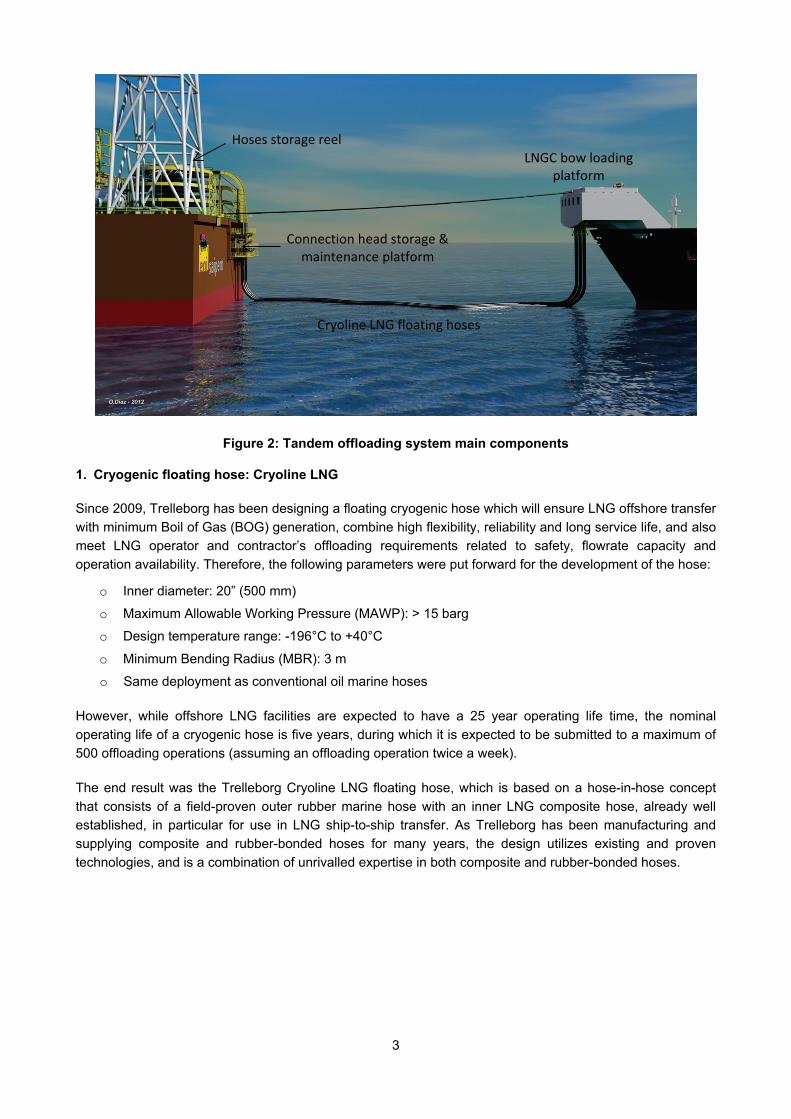
The LNG tandem offloading system developed by Saipem is composed of three Cryoline LNG floating hoses supplied by Trelleborg, a hose storage system, a connection head with a dedicated storage platform on the LNG terminal and a bow loading platform on the LNG carrier (see Figure 2).
3
Figure 2: Tandem offloading system main components
1. Cryogenic floating hose: Cryoline LNG Since 2009, Trelleborg has been designing a floating cryogenic hose which will ensure LNG offshore transfer with minimum Boil of Gas (BOG) generation, combine high flexibility, reliability and long service life, and also meet LNG operator and contractor’s offloading requirements related to safety, flowrate capacity and operation availability. Therefore, the following parameters were put forward for the development of the hose:
o Inner diameter: 20” (500 mm)
o Maximum Allowable Working Pressure (MAWP): > 15 barg
o Design temperature range: -196°C to +40°C
o Minimum Bending Radius (MBR): 3 m
o Same deployment as conventional oil marine hoses
However, while offshore LNG facilities are expected to have a 25 year operating life time, the nominal operating life of a cryogenic hose is five years, during which it is expected to be submitted to a maximum of 500 offloading operations (assuming an offloading operation twice a week).
The end result was the Trelleborg Cryoline LNG floating hose, which is based on a hose-in-hose concept that consists of a field-proven outer rubber marine hose with an inner LNG composite hose, already well established, in particular for use in LNG ship-to-ship transfer. As Trelleborg has been manufacturing and supplying composite and rubber-bonded hoses for many years, the design utilizes existing and proven technologies, and is a combination of unrivalled expertise in both composite and rubber-bonded hoses.
Hoses storage reel LNGC bow loading
platform
Connection head storage & maintenance platform
Cryoline LNG floating hoses

4
Figure 3: Cryoline LNG hose components
More specifically, the design of the floating cryogenic hose comprises the following key components (see Figure 3):
i. An inner cryogenic hose derived from the company’s composite hose technology best known for its high flexibility and proven suitability for LNG ship-to-ship transfer in side-by-side configuration. Composite LNG hoses usually consist of un-bonded, multiple polymeric film and woven fabric layers trapped between two stainless steel wire helices which give the hose its convoluted shape, one being internal and one external. Broadly, the film layers provide a fluid-tight barrier to the conveyed product, while the woven fabric layers provide the mechanical strength of the hose. The number and arrangement of multiple polymeric film and woven fabric layers is specific to the hose size and application. The polymeric film and fabric materials are selected to be compatible with the conveyed product and the extremes of operating temperature. Composite LNG hoses have already proven their suitability for such an application as this technology has been validated through many full scale static and dynamic tests, and many offshore ship-to-ship LNG transfers.
ii. An outer protective hose based on Trelleborg’s flexible rubber bonded hose technology, best known for its high resistance to fatigue and high ability to comply with harsh environment conditions. Rubber bonded hoses are usually made of rubber, steel rings, steel cable reinforcement layers and end-fittings. Trelleborg has been using a unique design since the mid 1970’s, derived from tire technology with integrated gasket flange system [2]. Rubber bonded hoses come typically in sections of 12 meters, which are bolted together in situ, either in horizontal or vertical assembly configuration. They might be used for floating or submarine configurations and are in conformity with OCIMF or API 17K specifications [3] [4]. Such a technology offers major technical and project execution advantages, making it a very attractive solution, especially from the perspective of overall offloading terminal optimization:
o A field-proven technology for marine oil & gas transfer applications as Trelleborg has been supplying rubber bonded hoses for nearly 40 years into the sector.
o A reliable technology based on OCIMF and/or API 17 K certifications. To demonstrate the fatigue life of rubber bonded hoses, Finite Element Analysis (FEA) tools have been specifically developed by Trelleborg during the qualification program in order to compute the stress within any steel wires or the strains within rubber layers.
o High resistance to fatigue as the rubber bonded hoses might include tapered Integrated Bending Stiffener (IBS) at each end, progressively decreasing the stress concentration in the flanges connection
o High thermal insulation properties and a corrosion free solution as the steel parts of the flanges are fully integrated within the rubber, leading to a corrosion free solution. Due to the high insulation performance of rubber (thermal conductivity about 0.3 W/m/K), rubber bonded hoses inherently show high thermal insulation properties.

5
o Suitable design for reeling configuration. Based on this technology, Trelleborg has supplied for more than 10 years, specific floating or submarine hoses for reeling applications in order to cure the main problems encountered with the permanently floating hose lines.
o Easy installation and maintenance operations as Trelleborg hoses might be assembled onshore or directly offshore. Also, the hose sections are easily surveyed and replaceable and as this technology is based on hose sections, offshore maintenance is both practicable and cost efficient.
iii. The annular space between the inner and outer hoses is filled with innovative and efficient insulation materials which have excellent properties over the full range of temperatures (from ambient to cryogenic temperatures). The insulation layer is designed so that no ice will form on the outer cover of the cryogenic hose. These materials have been designed to reduce heat loss within the structure, to protect the outer rubber bonded hose from cryogenic temperatures and to ensure Cryoline LNG hose buoyancy. Derived from advanced technologies, these materials – characterized by orthotropic properties – consist of an open structure, allowing to inert the annular space with nitrogen between each offloading operation. Moreover, they also have excellent resistance properties to dynamic loads (fatigue) generated by the application.
iv. An integrated leak monitoring system based on optical fibers technology (fiber Bragg grating sensors) for gas leak detection in the annular space between the inner and outer hoses. The two optical fibers – for redundancy purpose – equipped with distributed fiber Bragg grating sensors are wound around the composite LNG hose in order to check the evolution of temperature within the structure and prevent any abnormal situation during the offloading operations. The operator will therefore benefit from a fast, effective and reliable control system to monitor the offloading conditions. A fiber Bragg grating (FBG) is a type of distributed Bragg reflector constructed in a short segment of optical fiber that reflects particular wavelengths of light and transmits all others. This is achieved by creating a periodic variation in the refractive index of the fiber core, using an intense ultraviolet (UV) source such as a UV laser. Fiber Bragg gratings are typically used as direct sensing elements for strain and temperature. Specifically, such a reliable technology is used in instrumentation applications including seismology, pressure sensors for extremely harsh environments, and as downhole sensors in oil and gas wells for measurement of the effects of external pressure, temperature, seismic vibrations and inline flow measurement.
v. A compact and specific connection system, specifically designed for the application. Typically, the Cryoline LNG floating hoses will consist of 12-meter long sections, which will be connected together – either onshore or offshore – with threaded rods and nuts, in the same way as conventional flexible bonded hoses for oil application [2]. Trelleborg has therefore developed a new concept of end-fittings in order to ensure load transfer and leak tightness, and to minimize heat loss within the offloading lines. The design of the connection system includes dedicated seals for cryogenic application – single acting, spring-energized seals made with high-grade virgin polytetra-fluoroethylene (PTFE) based material – which are used for static and dynamic applications, exhibit excellent sealing integrity in gas and fluid applications and withstand rapid changes in temperature. The concept of the end-fittings has been developed through Finite Element Analysis (FEA) to take into account coupled thermal and mechanical loads at the very first steps of the design process. In a second step, the calculations have been validated through full scale tests performed on a dedicated test bench so as to validate the design of the connection system, to demonstrate the tightness of the connection design at room and cryogenic temperatures, and to endorse the choice of the cryogenic sealing technology. For example, cyclic compression loads up to 200 tons have been applied on a full scale connection, highlighting a safety factor of 10 in service conditions on the key components.
6
Derived from Trelleborg’s existing and proven technologies, the Cryoline LNG floating hose will be a key component of offloading systems for future offshore FLNG projects. By enabling offshore transfer of LNG in tandem configuration, the cryogenic floating hose will pioneer a step change in the safety of this critical operation. This innovative system will also allow FLNG projects to be considered in harsher conditions without excessive downtime due to offloading system availability, and with significantly reduced risk.
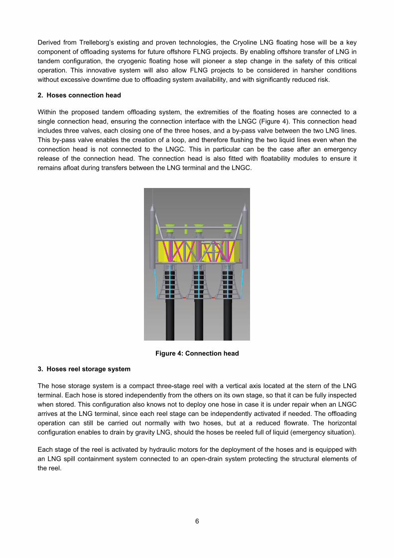
2. Hoses connection head Within the proposed tandem offloading system, the extremities of the floating hoses are connected to a single connection head, ensuring the connection interface with the LNGC (Figure 4). This connection head includes three valves, each closing one of the three hoses, and a by-pass valve between the two LNG lines. This by-pass valve enables the creation of a loop, and therefore flushing the two liquid lines even when the connection head is not connected to the LNGC. This in particular can be the case after an emergency release of the connection head. The connection head is also fitted with floatability modules to ensure it remains afloat during transfers between the LNG terminal and the LNGC.
Figure 4: Connection head
3. Hoses reel storage system The hose storage system is a compact three-stage reel with a vertical axis located at the stern of the LNG terminal. Each hose is stored independently from the others on its own stage, so that it can be fully inspected when stored. This configuration also knows not to deploy one hose in case it is under repair when an LNGC arrives at the LNG terminal, since each reel stage can be independently activated if needed. The offloading operation can still be carried out normally with two hoses, but at a reduced flowrate. The horizontal configuration enables to drain by gravity LNG, should the hoses be reeled full of liquid (emergency situation).
Each stage of the reel is activated by hydraulic motors for the deployment of the hoses and is equipped with an LNG spill containment system connected to an open-drain system protecting the structural elements of the reel.

7
Figure 5: Hoses reel storage system and the connection head maintenance & storage platform
A maintenance and storage platform is also installed on the aft transom of the LNG terminal to clamp the connection head between two transfer operations. After each LNG transfer operation, the platform enables the inspection of the connection head and the draining of the hoses from the possible remains of LNG after the flushing operation. Heavier maintenance operations are also possible thanks to the platform and the aft LNG terminal crane, such as the replacement of a hose section (anywhere along the hose string) or replacement of a connection head component on the LNG terminal main deck.
4. LNGC bow loading platform The connection of the hoses on the LNGC is made possible by the addition of a cantilever platform on its bow. This cantilever platform is designed to be sufficiently prominent to avoid any shock between the connection head and the LNGC’s bulb during an emergency release. The platform has an upper level equipped with the mooring equipment to connect the hawser from the LNG terminal. The upper level also houses the two winches used to transfer and lift the connection head and the hoses from the terminal in sea states with significant wave height up to 3.5m.
The lower level is fitted with the connection head clamping equipment and piping connection, including Quick Connect/Disconnect system (QC/DC) and emergency release coupling (ERC). During transit periods, this area is protected from green-water to preserve equipment.
Figure 6: View of the bow loading platform from the aft of the LNG terminal

8
OFFLOADING PROCEDURES
The procedures developed for the LNG tandem offloading system have been based on the common industry practices for oil tandem offloading and ship-to-shore LNG traditional loading operations. The purpose has been to adapt these well-known practices to the specificities of offshore LNG offloading as much as possible. The challenge was to keep operations simple and fast, despite the additional constraints created by the LNG transfer (three hoses, cool-down and inerting phases, etc.).
Mooring procedures, which are not specific to LNG, are directly derived from oil tandem offloading operations. Depending on site specific environmental conditions and the experience and preferences of operators, station keeping of the LNGC during the transfer operation can be handled in two different ways: either by using a single hawser kept taut by the main propulsion of the LNGC pulling backwards or by an aft tug, which will stabilize the position of the vessel longitudinally and transversally, or by using a DP (Dynamic Positioning) carrier and, usually, keeping the hawser loose as a back-up to prevent drift-off.
Once the LNGC is stable in its nominal tandem position, the hoses can be transferred from the LNG terminal to the bow loading platform of the LNGC. A messenger line transferred with the hawser connects the connection head to the winches of the LNGC. The hoses are unreeled while the winches are pulling the handling wires connected to the connection head at the same speed with some slack length to accommodate the relative motions of the LNGC relative to the connection head. The winches finally lift the connection head to the bow loading platform where it is rigidly clamped. This connection phase can be performed within sea states of significant wave height up to 3.5m. The hoses are fully unreeled at the end of their transfer. This means that the swivels in the reel are static when LNG is being transferred and that there are no moving mechanical parts, making the system operation simple and robust.
Once the connection head is clamped, the hoses connection to the LNGC piping can be performed. This connection is made in a sheltered zone with man-access, so that the flanges can be inspected and cleaned, if needed, before completing piping coupling. The spaces between the two end valves on connection head side and on LNGC side are inerted. Then, if all other parameters are satisfactory, the LNG transfer can start with a cool-down of the LNG lines first to limit the boil-off gas production and then with a ramp-up to the nominal LNG transfer flowrate. The 20” ID hoses enable a similar flowrate to the standard values onshore, i.e. 10,000 to 12,000m3/h.
Once connected, the system is designed to keep transferring LNG in sea states with significant wave height up to 4m. The use of floating hoses makes the requirement of station keeping capability of the LNGC, less stringent than for any other system.
When the transfer is completed, the LNG remaining in the lines is flushed by means of dry gas coming from the LNG terminal (typically boil-off gas or pre-treated gas depending on the LNG Terminal) while hoses are still connected to the LNGC, so that the hoses can be returned to the LNG terminal with a minimum inventory of hydrocarbon. A specificity of the system is that it is able to flush the lines even after an emergency disconnection where the connection head is disconnected from the LNGC and falls back at sea; LNG can be flushed due to the by-pass valve located in the connection head between the two LNG lines. Therefore, the lines can be reeled with the minimum hydrocarbon inventory, even in a case of emergency where all elements of risk should be avoided. Finally, even if the hoses were to be retrieved full of LNG for some operational reason, most of the liquid would be immediately gravity-drained into the LNG terminal header, leaving a minimum LNG inventory on the reel and the connection head platform.
Once the connection head is retrieved on the LNG terminal, the LNGC can release the hawser and depart. On the LNG terminal, the hoses are purged from the potential remaining LNG and inerted. Thus, they are stored at ambient temperature between two offloading operations. A visual inspection of all the parts of the hoses and connection head is performed to make sure the system will be operational for the next offloading operation.
9
TECHNOLOGY QUALIFICATION
In 2008, a specific European Standard EN 1474 [1] has been developed by the industry to give a common frame for the qualification of new LNG transfer systems and flexible hoses. The main challenge for this LNG tandem offloading system qualification is to qualify the LNG transfer floating hose according to the EN1474-2 standard, which gives general guidelines for the design, material selection, qualification, certification and testing details for LNG transfer hoses for offshore transfer in floating configurations. Such hoses need indeed to be durable when operating in the marine environment and to be flexible with a minimum bending radius compatible with the handling and operating requirements of the transfer system.
A qualification test program (QTP) has been therefore proposed by Trelleborg according to the European Standard EN 1474-2 requirements which comprise a complete set of full-scale tests. Additionally, laboratory testing on materials have to be performed in order to ascertain that mechanical properties are suitable for the intended application, and that components’ performance are not adversely affected by exposure to environment – both internal and external, e.g. LNG, NG or marine environment – over the hose design life. Typically, the following tests are required within the qualification process:
o Mechanical properties of all materials at ambient and cryogenic temperatures
o Effect of LNG exposure on all materials which are exposed to cryogenic temperature
o Effect of ambient climatic exposure on all materials which are exposed to atmosphere
o Effect of marine environment, e.g. corrosion of metallic components In addition, the qualification test program includes 23 destructive or non-destructive tests – either static or dynamic – in ambient or cryogenic conditions so that to demonstrate the ability of the cryogenic hose to operate in the foreseen configuration, e.g. capability of withstanding temperature/pressure cycles, capacity of operating at the maximum flow rate, and fatigue resistance to bending cycles.
Before the qualification phase, Trelleborg has been testing several reduced scale prototypes at ambient and cryogenic conditions in order to validate theories and demonstrate feasibilities. The design has already been validated by numerous characterization tests and qualification tests on 4” and 12” inner diameter hoses, including:
o Material testing at ambient and cryogenic temperatures, leading to a definitive selection of stainless steel grade, high performance polymers and insulation material
o Fatigue tests on reduced scale composite hose prototypes at cryogenic temperature in order to check the ability of materials to withstand a large number of bending cycles, simulating the fatigue loads the cryogenic hose will face in service condition.
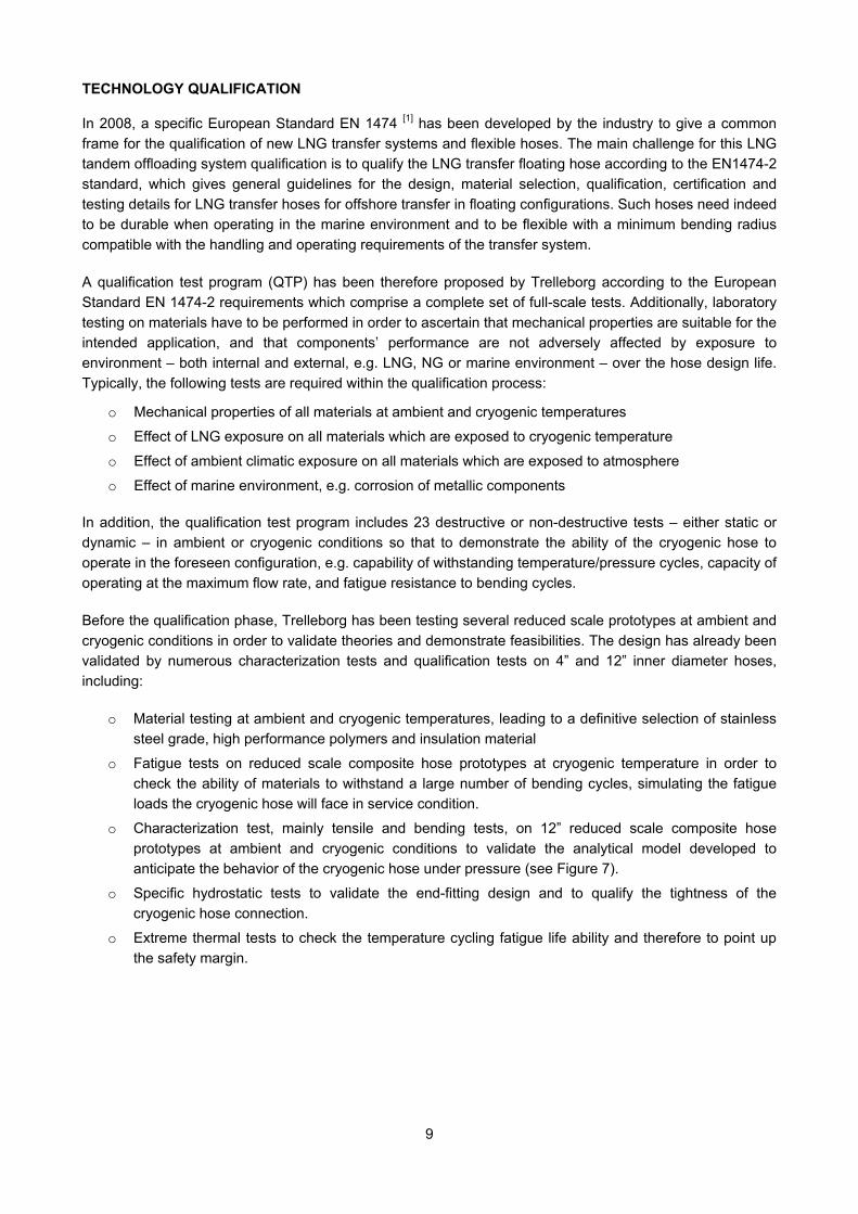
o Characterization test, mainly tensile and bending tests, on 12” reduced scale composite hose prototypes at ambient and cryogenic conditions to validate the analytical model developed to anticipate the behavior of the cryogenic hose under pressure (see Figure 7).
o Specific hydrostatic tests to validate the end-fitting design and to qualify the tightness of the cryogenic hose connection.
o Extreme thermal tests to check the temperature cycling fatigue life ability and therefore to point up the safety margin.
10
Figure 7: Cryogenic pressure tests on 12” prototypes (straight and bended configuration)
Validation tests on the monitoring system have been already completed on 12” and 20” Cryoline LNG prototypes, enabling to validate the thermal gradient identified through initial thermo-mechanical FEA and to check that there is no ice formation on the outer cover of the Cryoline LNG hose (see Figure 7).
Additional 12” Cryoline LNG prototype hoses have been manufactured and tested in order to validate the cryogenic hose design and prepare the qualification program on the 20” cryogenic hose. In 2013, several 20” Cryoline LNG prototypes will be tested in both static and dynamic conditions to demonstrate the suitability of a flexible hose for LNG transfer applications. In particular, a fatigue test will be completed on full scale prototypes – including a complete connection system – to prove that the Cryoline LNG withstands recurrent dynamic loads for long service life. Typically, the qualification test program includes a cryogenic bending cyclic fatigue test that will reproduces the dynamic load conditions to which the cryogenic hose will be submitted in service conditions.
The qualification of the 20” Cryoline LNG is expected to be completed in 2013.
Qualification of the other components of the system mostly relies on a risk analysis of the parts presenting some technological novelty. Specific requirements and studies have been established to provide guarantees that the system does not present major uncertainties. A concept approval by a classification society is expected to be granted during the first quarter in 2013.
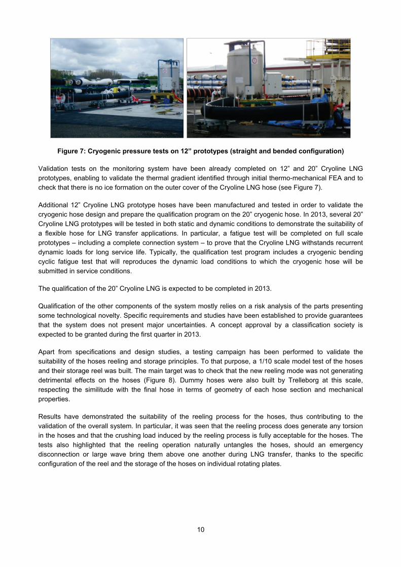
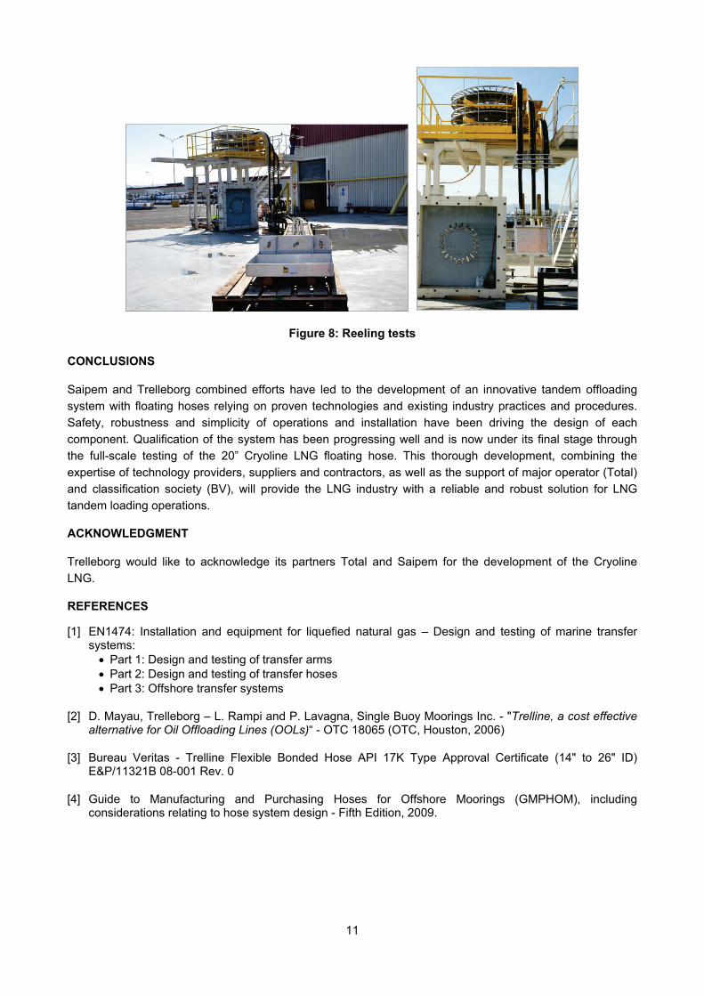
Apart from specifications and design studies, a testing campaign has been performed to validate the suitability of the hoses reeling and storage principles. To that purpose, a 1/10 scale model test of the hoses and their storage reel was built. The main target was to check that the new reeling mode was not generating detrimental effects on the hoses (Figure 8). Dummy hoses were also built by Trelleborg at this scale, respecting the similitude with the final hose in terms of geometry of each hose section and mechanical properties.
Results have demonstrated the suitability of the reeling process for the hoses, thus contributing to the validation of the overall system. In particular, it was seen that the reeling process does generate any torsion in the hoses and that the crushing load induced by the reeling process is fully acceptable for the hoses. The tests also highlighted that the reeling operation naturally untangles the hoses, should an emergency disconnection or large wave bring them above one another during LNG transfer, thanks to the specific configuration of the reel and the storage of the hoses on individual rotating plates.
11
Figure 8: Reeling tests
CONCLUSIONS
Saipem and Trelleborg combined efforts have led to the development of an innovative tandem offloading system with floating hoses relying on proven technologies and existing industry practices and procedures. Safety, robustness and simplicity of operations and installation have been driving the design of each component. Qualification of the system has been progressing well and is now under its final stage through the full-scale testing of the 20” Cryoline LNG floating hose. This thorough development, combining the expertise of technology providers, suppliers and contractors, as well as the support of major operator (Total) and classification society (BV), will provide the LNG industry with a reliable and robust solution for LNG tandem loading operations.
ACKNOWLEDGMENT
Trelleborg would like to acknowledge its partners Total and Saipem for the development of the Cryoline LNG.
REFERENCES
[1] EN1474: Installation and equipment for liquefied natural gas – Design and testing of marine transfer systems: • Part 1: Design and testing of transfer arms • Part 2: Design and testing of transfer hoses • Part 3: Offshore transfer systems
[2] D. Mayau, Trelleborg – L. Rampi and P. Lavagna, Single Buoy Moorings Inc. - "Trelline, a cost effective alternative for Oil Offloading Lines (OOLs)“ - OTC 18065 (OTC, Houston, 2006)
[3] Bureau Veritas - Trelline Flexible Bonded Hose API 17K Type Approval Certificate (14" to 26" ID) E&P/11321B 08-001 Rev. 0
[4] Guide to Manufacturing and Purchasing Hoses for Offshore Moorings (GMPHOM), including considerations relating to hose system design - Fifth Edition, 2009.