QTX SERIES Page 1 HEATER / FAN / LIGHT / NIGHT LIGHT READ ... · Page 2 MODEL QTX110HL TYPICAL...
8
Page 1 MODEL QTX110HL WARNING TO REDUCE THE RISK OF FIRE, ELECTRIC SHOCK, OR IN- JURY TO PERSONS, OBSERVE THE FOLLOWING: 1. Use this unit only in the manner intended by the manufac- turer. If you have questions, contact the manufacturer at the address or telephone number listed in the warranty. 2. Before servicing or cleaning unit, switch power off at service panel and lock the service disconnecting means to prevent power from being switched on accidentally. When the ser- vice disconnecting means cannot be locked, securely fasten a prominent warning device, such as a tag, to the service panel. 3. Installation work and electrical wiring must be done by a qualified person(s) in accordance with all applicable codes and standards, including fire-rated construction codes and standards. 4. Sufficient air is needed for proper combustion and exhaust- ing of gases through the flue (chimney) of fuel burning equip- ment to prevent backdrafting. Follow the heating equipment manufacturer’s guideline and safety standards such as those published by the National Fire Protection Association (NFPA), and the American Society for Heating, Refrigeration and Air Conditioning Engineers (ASHRAE), and the local code au- thorities. 5. When cutting or drilling into wall or ceiling, do not damage electrical wiring and other hidden utilities. 6. Ducted fans must always be vented to the outdoors. 7. Provide a separate 20 AMP circuit. Use 12 GA. power cable of type which meets code. 8. This unit must be grounded. CAUTION ! 1. For general ventilating use only. Do not use to exhaust haz- ardous or explosive materials and vapors. 2. This product is designed for installation in ceilings up to a 12/12 pitch. Duct connector must point up. DO NOT MOUNT THIS PRODUCT IN A WALL. 3. To avoid motor bearing damage and noisy and/or unbal- anced impellers, keep drywall spray, construction dust, etc. off power unit. 4. Please read specification label on product for further infor- mation and requirements. QTX SERIES HEATER / FAN / LIGHT / NIGHT LIGHT READ AND SAVE THESE INSTRUCTIONS CLEANING & MAINTENANCE WARRANTY BROAN-NUTONE THREE YEAR LIMITED WARRANTY Broan-NuTone warrants to the original consumer purchaser of its products that such products will be free from defects in materials or workmanship for a period of three years from the date of original purchase. THERE ARE NO OTHER WARRANTIES, EXPRESS OR IMPLIED, INCLUDING, BUT NOT LIMITED TO, IMPLIED WARRANTIES OF MERCHANT- ABILITY OR FITNESS FOR A PARTICULAR PURPOSE. During this three-year period, Broan-NuTone will, at its option, repair or replace, without charge, any product or part which is found to be defective under normal use and service. THIS WARRANTY DOES NOT EXTEND TO FLUORESCENT LAMP STARTERS AND TUBES. This warranty does not cover (a) normal maintenance and service or (b) any products or parts which have been subject to misuse, negligence, accident, improper mainte- nance or repair (other than by Broan-NuTone), faulty installation or installation contrary to recommended installation instructions. The duration of an implied warranty is limited to the three-year period as specified for the express warranty. Some states do not allow limitation on how long an implied war- ranty lasts, so the above limitation may not apply to you. BROAN-NUTONE’S OBLIGATION TO REPAIR OR REPLACE, AT BROAN-NUTONE’S OP- TION, SHALL BE THE PURCHASER’S SOLE AND EXCLUSIVE REMEDY UNDER THIS WARRANTY. BROAN-NUTONE SHALL NOT BE LIABLE FOR INCIDENTAL, CONSEQUEN- TIAL OR SPECIAL DAMAGES ARISING OUT OF OR IN CONNECTION WITH PRODUCT USE OR PERFORMANCE. Some states do not allow the exclusion or limitation of inciden- tal or consequential damages, so the above limitation may not apply to you. This warranty gives you specific legal rights, and you may also have other rights, which vary from state to state. This warranty supersedes all prior warranties. To qualify for warranty service, you must (a) notify Broan-NuTone at the address or telephone number stated below, (b) give the model number and part identification and (c) describe the nature of any defect in the product or part. At the time of requesting warranty service, you must present evidence of the original purchase date. Broan-NuTone LLC, 926 West State Street, Hartford, WI 53027 (1-800-637-1453) Installer: Leave this manual with the homeowner. For quiet and efficient operation, long life, and attractive ap- pearance - lower or remove grille and vacuum interior of unit with the dusting brush attachment. The motor is permanently lubricated and never needs oiling. If the motor bearings are making excessive or unusual noises, replace the motor with the exact service motor. The impeller should also be replaced. Replace light bulbs with (2) 60-Watt (maximum) incandescent light bulbs and (1) 7-Watt night light bulb. OPERATION Use a 4-Function Control to operate the heater, fan, light, and night light separately. See “Connect Wiring” for details. NOTE: This unit is designed with a thermostat which senses excess heat and may start the blower automatically. This is normal and is no cause for concern. NOTE: Fan may cycle when light is on. Blinking light may indi- cate improper lamp wattage or type.
Transcript of QTX SERIES Page 1 HEATER / FAN / LIGHT / NIGHT LIGHT READ ... · Page 2 MODEL QTX110HL TYPICAL...
Page 1
MODEL QTX110HL
WARNING TO REDUCE THE RISK OF FIRE, ELECTRIC SHOCK, OR IN-JURY TO PERSONS, OBSERVE THE FOLLOWING:1. Use this unit only in the manner intended by the manufac-
turer. If you have questions, contact the manufacturer at theaddress or telephone number listed in the warranty.
2. Before servicing or cleaning unit, switch power off at servicepanel and lock the service disconnecting means to preventpower from being switched on accidentally. When the ser-vice disconnecting means cannot be locked, securely fastena prominent warning device, such as a tag, to the servicepanel.
3. Installation work and electrical wiring must be done by aqualified person(s) in accordance with all applicable codesand standards, including fire-rated construction codes andstandards.
4. Sufficient air is needed for proper combustion and exhaust-ing of gases through the flue (chimney) of fuel burning equip-ment to prevent backdrafting. Follow the heating equipmentmanufacturer’s guideline and safety standards such as thosepublished by the National Fire Protection Association (NFPA),and the American Society for Heating, Refrigeration and AirConditioning Engineers (ASHRAE), and the local code au-thorities.
5. When cutting or drilling into wall or ceiling, do not damageelectrical wiring and other hidden utilities.
6. Ducted fans must always be vented to the outdoors.7. Provide a separate 20 AMP circuit. Use 12 GA. power cable
of type which meets code.8. This unit must be grounded.
CAUTION !1. For general ventilating use only. Do not use to exhaust haz-
ardous or explosive materials and vapors.2. This product is designed for installation in ceilings up to a
12/12 pitch. Duct connector must point up. DO NOT MOUNTTHIS PRODUCT IN A WALL.
3. To avoid motor bearing damage and noisy and/or unbal-anced impellers, keep drywall spray, construction dust, etc.off power unit.
4. Please read specification label on product for further infor-mation and requirements.
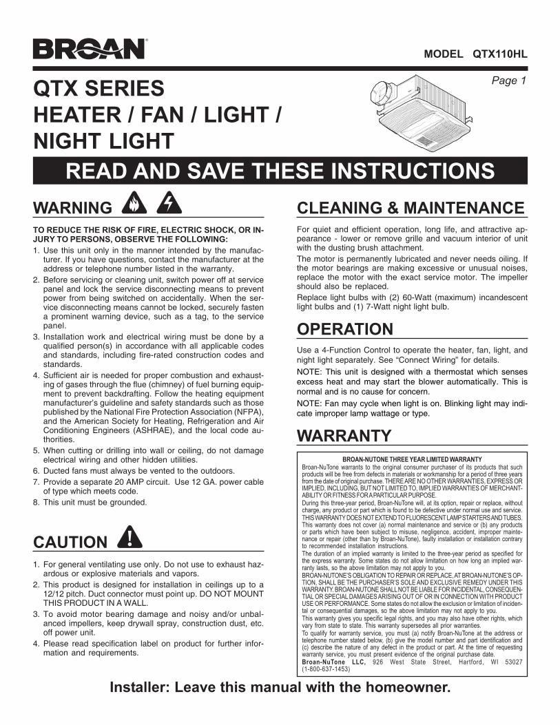
QTX SERIESHEATER / FAN / LIGHT /NIGHT LIGHT
READ AND SAVE THESE INSTRUCTIONSCLEANING & MAINTENANCE
WARRANTYBROAN-NUTONE THREE YEAR LIMITED WARRANTY
Broan-NuTone warrants to the original consumer purchaser of its products that suchproducts will be free from defects in materials or workmanship for a period of three yearsfrom the date of original purchase. THERE ARE NO OTHER WARRANTIES, EXPRESS ORIMPLIED, INCLUDING, BUT NOT LIMITED TO, IMPLIED WARRANTIES OF MERCHANT-ABILITY OR FITNESS FOR A PARTICULAR PURPOSE.During this three-year period, Broan-NuTone will, at its option, repair or replace, withoutcharge, any product or part which is found to be defective under normal use and service.THIS WARRANTY DOES NOT EXTEND TO FLUORESCENT LAMP STARTERS AND TUBES.This warranty does not cover (a) normal maintenance and service or (b) any productsor parts which have been subject to misuse, negligence, accident, improper mainte-nance or repair (other than by Broan-NuTone), faulty installation or installation contraryto recommended installation instructions.The duration of an implied warranty is limited to the three-year period as specified forthe express warranty. Some states do not allow limitation on how long an implied war-ranty lasts, so the above limitation may not apply to you.BROAN-NUTONE’S OBLIGATION TO REPAIR OR REPLACE, AT BROAN-NUTONE’S OP-TION, SHALL BE THE PURCHASER’S SOLE AND EXCLUSIVE REMEDY UNDER THISWARRANTY. BROAN-NUTONE SHALL NOT BE LIABLE FOR INCIDENTAL, CONSEQUEN-TIAL OR SPECIAL DAMAGES ARISING OUT OF OR IN CONNECTION WITH PRODUCTUSE OR PERFORMANCE. Some states do not allow the exclusion or limitation of inciden-tal or consequential damages, so the above limitation may not apply to you.This warranty gives you specific legal rights, and you may also have other rights, whichvary from state to state. This warranty supersedes all prior warranties.To qualify for warranty service, you must (a) notify Broan-NuTone at the address ortelephone number stated below, (b) give the model number and part identification and(c) describe the nature of any defect in the product or part. At the time of requestingwarranty service, you must present evidence of the original purchase date.Broan-NuTone LLC, 926 West State Street, Hartford, WI 53027(1-800-637-1453)
Installer: Leave this manual with the homeowner.
For quiet and efficient operation, long life, and attractive ap-pearance - lower or remove grille and vacuum interior of unitwith the dusting brush attachment.The motor is permanently lubricated and never needs oiling. Ifthe motor bearings are making excessive or unusual noises,replace the motor with the exact service motor. The impellershould also be replaced.Replace light bulbs with (2) 60-Watt (maximum) incandescentlight bulbs and (1) 7-Watt night light bulb.
OPERATIONUse a 4-Function Control to operate the heater, fan, light, andnight light separately. See “Connect Wiring” for details.NOTE: This unit is designed with a thermostat which sensesexcess heat and may start the blower automatically. This isnormal and is no cause for concern.NOTE: Fan may cycle when light is on. Blinking light may indi-cate improper lamp wattage or type.

Page 2
MODEL QTX110HL
TYPICAL INSTALLATION
HOUSING
CEILINGJOIST, TRUSS,
OR I-JOISTS
MOUNTINGCHANNELS
GRILLECEILING
MATERIAL
POWERCABLES
Housing mounted directly to joists, trusses, or I-joists.Up to 24-inches on-center.
Unit shown connected to 6-inch round ductwork.
ROOF CAP *
6-IN. ROUNDELBOW *
6-IN. ROUNDDUCT *
WALLCAP *
* Purchase separately
PLAN THE INSTALLATION
The unit will operate most quietly and efficiently when locatedwhere the shortest possible duct run and minimum number ofelbows will be needed.
Plan to supply the unit with proper line voltage and appropriatepower cable.
INSTALLATION
2. Mounthousing.Secure housingto ceilingstructure with (4)mounting screws.Make surebottom ofhousing will beflush withfinished ceilingmaterial.
1. Insertmountingbrackets.Slide the (4)mountingbrackets into thechannels oneach end of thehousing.
3. Attachdamper /ductconnectorto housing.Snap damper /duct connectoronto housing.Make sureconnector isflush with top ofhousing and damper flap falls closed.
4. Install 6-inch roundductwork.Connect 6-inchround ductworkto damper / ductconnector. Runductwork to aroof cap or wallcap. Tape allductworkconnections tomake them secure and air tight.

Page 3
MODEL QTX110HL
8. Plug-in light.Hold grilleassembly upnear housing.Connect lightplug from grilleassembly toreceptacle insideof housing.
INSTALL GRILLE & BULBS
9. Attachgrille.Remove the (2)grille mountingscrews from thesides of thehousing. (SeeStep 8 illustra-tion.) Use thesescrews to attachthe grille to thehousing asshown.
To avoid damage to the grille: DO NOT OVERTIGHTENSCREWS. Tighten screws only until grille is snug againstceiling material.
10. Installbulbs.The unitaccepts (2) 60-Watt (maxi-mum) incan-descent bulbsand (1) 7-Wattnight light bulb.
11. Attachlight lens.Hook the tabson one end ofthe lens into theslot in the grille.Lift other end oflens up andsnap into place.
GRILLE MOUNTINGSCREWS
5. Connect electrical wiring.Run 120 VAC house wiring to installation location. Useproper UL approved connectors to secure house wiring towiring plate. Connect wires as shown in wiringdiagram(s).
CONNECT WIRING
INSTALL GRILLE & BULBS
7. Removelight lensfrom grille.Insert a small flat-bladed screw-driver into the slotat one end of thelight lens.Carefully pry thelens out.
6. Finish ceiling.Install ceiling material. Cut out ceiling material closelyaround housing.
WHITEto
WHITE
HEAT (2-position rocker)
LIGHT (red)NIGHT LIGHT (blue)(3-position rocker)
4-FUNCTION CONTROL
GROUND
120 VAC LINE IN
BLACK to BLUE
BLACK to RED
BLACK to BLACKS
FAN (2-position rocker)
RED
RED
WIRING PLATEFROM VENTILATOR
VENTILATORHOUSING
LIGHT&
FAN
HEAT&
NIGHT LIGHT
BLACK to BLUE(Light)
WHITE to WHITE
RED to RED(Fan)
RED to BLACK(Heat)
BLACK to YELLOW(Night Light)
WHITE to WHITE
CAUTIONRATING SPECIFICATIONS• The three-position
rocker switch is rated 5 A@ 125VAC. Use this switchfor Lights ONLY.
• Each two-position rockerswitch is rated 15 A @ 120VAC. Use these switches for Heat and Vent.
• The total load on this control must not exceed 20 A @ 120VAC.
Broan 4-FunctionControl shown
(purchase separately)

Page 4
MODEL QTX110HL
SERVICE PARTSKey No. Part No. Description
1 97016470 Housing2 98007763 Slide Channel (2 req.)3 98003036 Support Angle (4 req.)4 97016450 Duct Connector5 99170245 Screw #8-18 X .375 (8 req.)6 93260454 Nut, Sheet Metal #8-18 (Partition)
(2 req.)7 99260512 Nut, Sheet Metal #8-18 (Grille)
(3 req.)8 98010091 Cover/KO Panel9 99150471 Screw, Ground (2 req.)
10 97016563 Wire Panel/Harness Assembly11 98010090 Wire Compartment12 98010089 Mounting Bracket-Heater13 99150415 Screw #8-18 X .250 (4 req.)14 99260488 Nut, Hex #10-24 (5 req.)15 97016564 Heater Scroll16 99020283 Wheel-Heater17 99260423 Nut, Hex #8-32 (4 req.)18 98010088 Motor Mount19 99080558 Motor-Heater20 97016565 Heating Element
(includes Key No. 7)97016566 Heater Scroll Assembly
(includes Key Nos. 12 thru 20)21 99020284 Wheel-Fan22 99080556 Motor-Fan23 99100491 Isolator (4 req.)24 97016471 Partition25 99250959 Washer (4 req.)26 99260558 Nut, Hex Lock #8-32 (4 req.)
97016567 Blower Assembly(includes Key Nos. 21 thru 26)
27 93150459 Screw #8-18 X .500 (2 req.)28 97016474 Grille Assembly
(includes Key No. 29)29 99111291 Lens30 99150622 Screw, Grille #8-18 X 2.000 (2 req.)
5 8
2
3
19
57
7
2
4
10
55
11
1419
18
2013
1716
15
1213
14
21
22
23
24
25
26
30
6
7
29
28
27
3
99043413G

Página 5
MODELO QTX110HL
ADVERTENCIA PARA REDUCIR EL RIESGO DE INCENDIOS, DESCARGASELÉCTRICAS O LESIONES PERSONALES, OBSERVE LASSIGUIENTES PRECAUCIONES:1. Use la unidad sólo de la manera indicada por el fabricante.
Si tiene preguntas, comuníquese con el fabricante a la direccióno al número telefónico que se incluye en la garantía.
2. Antes de dar servicio a la unidad o de limpiarla, interrumpa elsuministro eléctrico en el panel de servicio y bloquee los mediosde desconexión del servicio para evitar que la electricidad sereanude accidentalmente. Cuando no sea posible bloquear losmedios de desconexión del servicio, fije firmemente en un lugarprominente del panel de servicio un dispositivo de advertencia,como por ejemplo una etiqueta.
3. Una o más personas calificadas deben realizar el trabajo deinstalación y el cableado eléctrico, de acuerdo con todos loscódigos y normas correspondientes, incluidos los códigos ynormas de construcción específicos de protección contraincendios.
4. Se necesita suficiente aire para que se lleve a cabo la combustióny descarga adecuadas de los gases a través del tubo de humos(chimenea) del equipo quemador de combustible, con el fin deevitar los contratiros. Siga las directrices y normas de seguridaddel fabricante del equipo de calefacción, tales como las publicadaspor la Asociación Nacional de Protección contra Incendios (Na-tional Fire Protection Association, NFPA), la Sociedad Americanade Ingenieros de Calefacción, Refrigeración y Aire Acondicionado(American Society for Heating, Refrigeration and Air ConditioningEngineers, ASHRAE) y las autoridades de los códigos locales.
5. Al cortar o perforar a través de la pared o del cielo raso, no dañeel cableado eléctrico ni otros servicios ocultos.
6. Los ventiladores con conductos siempre se deben conectar haciael exterior.
7. Provea un circuito por separado de 20 AMP. Use un cable depotencia 12 GA. del tipo conforme al código.
8. Esta unidad se debe conectar a tierra.
PRECAUCIÓN !1. Sólo para usarse en ventilación general. No se use para descargar
materiales ni vapores peligrosos o explosivos.2. Este producto se diseña para la instalación en techos hasta una
echada de 12/12. Conector de conductor debe señalar hacia arriba.NO MONTE ESTE PRODUCTO EN UNA TECHO.
3. Para evitar daños a los cojinetes del motor y rotores ruidosos y/o noequilibrados, mantenga la unidad de accionamiento al resguardo derociados de yeso, polvos de construcción, etc.
4. Lea la etiqueta de especificaciones del producto para ver informacióny requisitos adicionales.
SERIE QTXCALEFACTOR / VENTILADOR /LUZ / LUZ DE NOCHE
LEA Y CONSERVE ESTAS INSTRUCCIONESLIMPIEZA Y MANTENIMIENTO
GARANTIA
A la persona que realiza la instalación: Deje este manual con el dueño de la casa.
Para obtener una operación silenciosa y eficiente, una larga vida y unaapariencia atractiva, baje o retire la rejilla y aspire el interior de la unidadcon el accesorio del cepillo para sacudir polvo.El motor está permanentemente lubricado y nunca necesitará aceite. Silos cojinetes del motor están haciendo ruido excesivo o inusual,reemplace el motor con el motor de servicio exacto. El impulsor tambiéndebe ser reemplazado.Reemplace los focos con dos (2) focos incandescentes de 60 watts(máximo) y un (1) foco de luz nocturna de 7 watts.
OPERACIÓN
GARANTIA BROAN-NUTONE LIMITADA POR TRES AÑOSBroan-NuTone garantiza al consumidor comprador original de sus productos que dichos productoscarecerán de defectos en materiales o en mano de obra por un período de tres años a partir de la fechaoriginal de compra. NO EXISTEN OTRAS GARANTIAS, EXPLICITAS O IMPLICITAS, INCLUYENDO,PERO NO LIMITADAS A, GARANTIAS IMPLICITAS DE COMERCIALIZACION O APTITUD PARA UNPROPOSITO PARTICULAR.Durante el período de tres años, y a su propio criterio, Broan-NuTone reparará o reemplazará, sin costoalguno cualquier producto o pieza que se encuentre defectuosa bajo condiciones normales de servicioy uso.ESTA GARANTIA NO SE APLICA A TUBOS Y ARRANCADORES DE LAMPARAS FLUORESCENTES.Esta garantía no cubre (a) mantenimiento y servicio normales o (b) cualquier producto o piezas quehayan sido utilizadas de forma errónea, negligente, que hayan causado un accidente, o que hayan sidoreparadas o mantenidas inapropiadamente (por otras compañías que no sean Broan-NuTone), instalacióndefectuosa, o instalación contraria a las instrucciones de instalación recomendadas.La duración de cualquier garantía implícita se limita a un período de tres años como se especifica enla garantía expresa. Algunos estados no permiten limitaciones en cuanto al tiempo de expiración deuna garantía implícita, por lo que la limitación antes mencionada puede no aplicarse a usted.LA OBLIGACION DE BROAN-NUTONE DE REPARAR O REEMPLAZAR, SIGUIENDO EL CRITERIODE BROAN-NUTONE, DEBERA SER EL UNICO Y EXCLUSIVO RECURSO LEGAL DEL COMPRADORBAJO ESTA GARANTIA. BROAN-NUTONE NO SERA RESPONSABLE POR DAÑOS INCIDENTALES,CONSIGUIENTES, O POR DAÑOS ESPECIALES QUE SURJAN A RAIZ DEL USO O DESEMPEÑODEL PRODUCTO. Algunos estados no permiten la exclusión o limitación de daños incidentales oconsiguientes, por lo que la limitación antes mencionada puede no aplicarse a usted.Esta garantía le proporciona derechos legales específicos, y usted puede también tener otros derechos,los cuales varían de estado a estado. Esta garantía reemplaza todas las garantías anteriores.Para calificar en la garantía de servicio, usted debe (a) notificar a Broan-NuTone al domicilio o al númerode teléfono abajo, (b) dar el número del modelo y la identificación de la pieza, y (c) describir la naturalezade cualquier defecto en el producto o pieza. En el momento de solicitar servicio cubierto por la garantía,usted debe de presentar evidencia de la fecha original de compra.Broan-NuTone LLC, 926 West State Street, Hartford, WI 53027 (1-800-637-1453)
Utilice un control de 4 funciones para operar el calefactor, el ventilador,la luz y la luz nocturna por separado. Vea los detalles en "Conexióneléctrica".NOTA: Esta unidad ha sido diseñada con un termostato que detecta losexcesos de calor y puede encender el soplador automáticamente. Estoes normal y no debe ser motivo de preocupación.NOTA: El ventilador puede completar un ciclo por intervalos cuando laluz está encendido. La luz del intermitente puede indicar vatiaje o el tipoincorrecto de la lámpara.

Página 6
MODELO QTX110HL
INSTALACIÓN TÍPICA
CUBIERTA
RANURAS DE MONTAJE
REJILLA
VIGA DE TECHO, TIRANTE O VIGA EN I
MATERIAL DEL CIELO RASO
CABLES DE ELECTRICIDAD
La cubierta se monta directamente sobre lasvigas, tirantes o vigas en I.
Hasta 24 pulgadas en centro.
La unidad ilustrada está conectada a un conductoredondo de 6 pulg.
TAPA DE TECHO *
CODOREDONDO DE
6 PULG. *
CONDUCTOREDONDO DE
6 PULG. *
TAPA DE
PARED ** Se compran por separado
PLANIFICACIÓN DE LAINSTALACIÓN
El ventilador funcionará con más eficiencia y menos ruido si seubica en un sitio donde requiera el tramo de conducto más cortoposible y un mínimo número de codos.
Alimente la unidad con el voltaje de línea y el cable eléctricoapropiados.
INSTALACIÓN
2. Monte lacubierta.Fije la cubierta a laestructura del cieloraso con cuatro (4)tornillos demontaje.Asegúrese de quela parte inferior dela cubierta esté anivel con elmaterial terminadodel cielo raso.
1. Inserte lossoportes demontaje.Deslice los (4)soportes demontaje en lasranuras en cadaextremo de lacubierta.
3. Acople elconector delreguladorde tiro/conducto ala cubierta.Conecte a presiónel conector delregulador de tiro/conducto en lacubierta.Asegúrese de que el conector esté al ras con la parte superiorde la cubierta y que la aleta del regulador caiga cerrada.
4. Instale elconductoredondo de6 pulg.Conecte elconducto redondode 6 pulg. alconector delregulador /conducto.Extienda elconducto haciauna tapa de techo o tapa de pared. Encinte todas lasconexiones de los conductos para fijarlas y hacerlasherméticas al aire.

Página 7
MODELO QTX110HL
8. Conecte elfoco.Sostenga elconjunto de larejilla cerca de lacubierta. Conecteel foco delconjunto de larejilla alreceptáculo dentrode la cubierta.
INSTALE LA REJILLA Y LOSFOCOS
9. Fije larejilla.Quite los dos (2)tornillos demontaje de larejilla de los ladosde la cubierta.(Vea la ilustraciónde paso 8.) Utiliceestos tornillospara fijar la rejillaa la cubierta, talcomo se muestra.Para evitar daños en la rejilla: NO APRIETE DE MÁS LOSTORNILLOS. Apriete los tornillos hasta que la rejilla estéfirmemente ceñida contra el material del cielo raso.
10. Instale losfocos.La unidad aceptados (2) focosincandescentesde 60 watts(máximo) y un (1)foco de luznocturna de7 watts.
11. Fije la lentede la luz.Enganche laslengüetas por unextremo de lalente en la ranurade la rejilla.Levante el otroextremo de lalente y fíjela en sulugar.
TORNILLOS DE MONTAJEDE LA REJILLA
5. Conecte los cables eléctricos.Extienda el cableado de la casa de 120 VCA al lugar de lainstalación. Utilice conexiones aprobadas por UL para asegurarel cableado de la casa a la placa de cableado. Conecte loscables tal como se ilustra en los diagramas de cableado.
CONEXIÓN ELÉCTRICA
INSTALE LA REJILLA Y LOS FOCOS
7. Quite la lentedel foco de larejilla.Inserte un pequeñodestornillador planoen la rejilla en unextremo de la lentedel foco. Hagapalanca concuidado para retirarla lente.
6. Termine el cielo raso.Instale el material del cielo raso. Recorte el material del cieloraso de cerca alrededor de la cubierta.
BLANCOa
BLANCO
CALENTADOR(interruptor 2-posición)
LUZ (rojo)LUZ DE NOCHE (azul)(3-position rocker)
CONTROL DE4 FUNCIONNES
TIERRA
LINEA DE ENTRADA120 VCA
NEGRO a AZUL
NEGRO a ROJO
NEGRO a NEGROS
VENTILADOR(interruptor 2-posición)
ROJO
ROJO
PLACA DE CABLEDE VENTILADOR
CAJA DEL VENTILADOR
LUZY
VENTILADOR
CALENTADORY
LUZ DE NOCHE
NEGRO a AZUL(Luz)
ROJO a ROJO(Ventilador)
ROJO a NEGRO(Calentador)
NEGRO a AMARILLO(Luz de noche)
BLANCO a BLANCO BLANCO a BLANCO
CUIDADOESPECIFICACIONESDEL GRADO• El interruptor de eje de
balancín de tres posicioneses clasificado 5 A @125VCA. Utilice esteinterruptor para las luces SOLAMENTE.
• El interruptor de eje de balancín de dos posiciones es clasificado 15 A@ 120VCA. Utilice estos interruptores para el calor y el ventilador.
• La carga total en este control no debe excederse 20 A @ 120VCA.
Broan control para4-funciones ilustrado(comprar separado)

Página 8
MODELO QTX110HL
PIEZAS DE REPUESTOClave No. Pieza No. Descripción
1 97016470 Cubierta2 98007763 Ranura de deslizamiento
(se req. 2)3 98003036 Ángulo de soporte (se req. 4)4 97016450 Conector del conducto5 99170245 Tornillo, #8-18 x 0.375 (se req. 8)6 93260454 Tuerca de chapa #8-18 (División)
(se req. 2)7 99260512 Tuerca de chapa #8-18 (Rejilla)
(se req. 3)8 98010091 Cubierta/ Panel KO9 99150471 Tornillo de conexión a tierra
(se req. 2)10 97016563 Conjunto del panel de
cableado/arnés11 98010090 Compartimiento de cables12 98010089 Soporte de montaje-Calefactor13 99150415 Tornillo, #8-18 x 0.250 (se req. 4)14 99260488 Tuerca hexagonal #10-24
(se req. 5)15 97016564 Desplazador del calefactor16 99020283 Disco-Calefactor17 99260423 Tuerca hexagonal #8-32
(se req. 4)18 98010088 Montaje del motor19 99080558 Motor-Calefactor20 97016565 Elemento de calefacción
(incluye clave no. 7)97016566 Conjunto del desplazador del
calefactor (incluye clave nos.12 á 20)
21 99020284 Disco-Ventilador22 99080556 Motor-Ventilador23 99100491 Aislante (se req. 4)24 97016471 División25 99250959 Arandela (se req. 4)26 99260558 Tuerca hexagonal de
seguridad #8-32 (se req. 4)97016567 Conjunto del ventilador
(incluye clave nos. 21 á 26)27 93150459 Tornillo, #8-18 x 0.500 (se req. 2)28 97016474 Conjunto de la rejilla
(incluye clave no. 29)29 99111291 Lentes30 99150622 Tornillo de la rejilla, #8-18 x 2.000
(se req. 2)
99043413G
5 8
2
3
19
57
7
2
4
10
55
11
1419
18
2013
1716
15
1213
14
21
22
23
24
25
26
30
6
7
29
28
27
3