QSI Quantum HO Equipped Locomotives - Q.S.Industriesqsindustries.com/manuals/DC analog reference...
86
DC Analog Reference Manual for QSI Quantum ® HO Equipped Locomotives Version 4.0 For Firmware Version 7 25 August 2006
Transcript of QSI Quantum HO Equipped Locomotives - Q.S.Industriesqsindustries.com/manuals/DC analog reference...

DC Analog Reference Manualfor
QSI Quantum® HO EquippedLocomotives
Version 4.0For Firmware Version 7
25 August 2006

Analog DC Reference Manual Version 4.0 2/86 25 August 2006
Table of ContentsIntroduction to Quantum Q1a Analog Operation.......................................................................................................... 6
New Features .......................................................................................................................................................................................................6Q1 and Q1a Analog Operation.............................................................................................................................................................................6
Basic Analog Operation (Quick Start) ........................................................................................................................... 8Running the Locomotive.......................................................................................................................................................................................8Reversing the Locomotive....................................................................................................................................................................................8Whistle/Horn.........................................................................................................................................................................................................8Bell (available on all U.S. or other selected models) ............................................................................................................................................8
Advanced Analog Features ............................................................................................................................................ 9Starting the Locomotive........................................................................................................................................................................................9Advanced Whistle/Horn Operation .......................................................................................................................................................................9Automatic Features ............................................................................................................................................................................................10Neutral................................................................................................................................................................................................................10Changing the Locomotive’s Direction without Turning off the Sound.................................................................................................................10Train Load ..........................................................................................................................................................................................................11Sound-of-Power™..............................................................................................................................................................................................11Helpers ...............................................................................................................................................................................................................11Normal and Reversed Direction .........................................................................................................................................................................12Standard Throttle Control™ (STC™) and Regulated Throttle Control™ (RTC™) .............................................................................................12Train Load ..........................................................................................................................................................................................................12Additional Analog Operation Features Available with the Quantum Engineer™ Controller ...............................................................................14Quantum Engineer Features ..............................................................................................................................................................................15
Analog Programming.................................................................................................................................................... 16Diesel, Electric and Gas Turbine Locomotive Programming..............................................................................................................................16Steam Programming ..........................................................................................................................................................................................17Entering Programming .......................................................................................................................................................................................18Scrolling through the Program Options ..............................................................................................................................................................18Entering a Program Option and Making Changes..............................................................................................................................................18Moving on to Other Program Options or Leaving Programming ........................................................................................................................18
Feature Programming Options (POP’s)....................................................................................................................... 19System Volume (POP 1) ....................................................................................................................................................................................19Load (POP 2) ....................................................................................................................................................................................................19Helper (POP 3)..................................................................................................................................................................................................20Direction (POP 4) ..............................................................................................................................................................................................20Setting V-Start (POP 8) ......................................................................................................................................................................................21V-Max (POP 9) ...................................................................................................................................................................................................21Setting Throttle Mode (POP 10) .........................................................................................................................................................................22
Special Programming Options..................................................................................................................................... 23System Reset (POP 11) .....................................................................................................................................................................................23About “Quantum” (POP 12)................................................................................................................................................................................23Feature Sound Volume ......................................................................................................................................................................................24Whistle/Horn Volume (POP 13)..........................................................................................................................................................................24Bell Volume (POP 14) ........................................................................................................................................................................................24Steam Chuff/Diesel Motor/Electric Traction Motor Volume (POP 15) ................................................................................................................25Steam Blower Hiss/ Diesel and Electric Cooling Fans Volume (POP 16)..........................................................................................................25Turbo Volume (POP 17) (Diesel and Gas Turbine Only) ..................................................................................................................................25Cocks Volume (POP 17) (Steam Only) .............................................................................................................................................................26Whoosh Volume (POP 18) (Gas Turbine Only) ................................................................................................................................................26Whine Volume (POP 19) (Gas Turbine Only) ...................................................................................................................................................26Air Brakes Volume (POP 20)..............................................................................................................................................................................27Air Pump Volume (POP 26) ...............................................................................................................................................................................27

Analog DC Reference Manual Version 4.0 3/86 25 August 2006
Long Air Let-off Volume (POP 27)......................................................................................................................................................................28Short Air Let-off Volume (POP 28) .....................................................................................................................................................................28Squealing Brake/Flange Volume (POP 30)........................................................................................................................................................28Dynamic Brakes Volume (POP 31) (Diesel, Electric and Gas Turbine only)......................................................................................................29Coupler Volume (POP 32)..................................................................................................................................................................................29Dynamo Volume (POP 46) (Steam only) ..........................................................................................................................................................30Pop-Off Volume (POP 47) (Steam only) ............................................................................................................................................................30Injector Volume (POP 49) (Steam only) .............................................................................................................................................................31
Appendix I: Quantum System Sounds ....................................................................................................................... 321.0 Steam Sounds..............................................................................................................................................................................................32
1.1 Automatic Sounds....................................................................................................................................................................................321.2 Controllable Sounds.................................................................................................................................................................................32
2.0 Diesel Sounds ..............................................................................................................................................................................................342.1 Automatic Sounds....................................................................................................................................................................................342.2 Controllable Sounds.................................................................................................................................................................................34
3.0 Electric Locomotive Sounds ........................................................................................................................................................................363.1 Automatic Sounds....................................................................................................................................................................................363.2 Controllable Sounds.................................................................................................................................................................................36
4.0 Gas Turbine Sounds ....................................................................................................................................................................................384.1 Automatic Sounds....................................................................................................................................................................................384.2 Controllable Sounds.................................................................................................................................................................................38
Appendix II: Special Hardware Operations ................................................................................................................. 40Using the Quantum Hardware Reset and Volume Controls: ..............................................................................................................................40Reset Jumper Models ........................................................................................................................................................................................40To Reset the Locomotive ...................................................................................................................................................................................40To Adjust the Volume Using the Potentiometer .................................................................................................................................................41Magnetic Wand Models......................................................................................................................................................................................41To Reset the Locomotive ...................................................................................................................................................................................42To Adjust the Volume Using the Magnetic Wand...............................................................................................................................................42Turn Your Locomotive On, using the Magnetic Wand........................................................................................................................................42High Voltage Circuit Breaker (Analog and DCC)................................................................................................................................................42
Appendix IIIa: Prototype Gas Turbine ......................................................................................................................... 43Introduction.........................................................................................................................................................................................................43Design and Description ......................................................................................................................................................................................43
Diesel Motor ...................................................................................................................................................................................................43Gas Turbine ...................................................................................................................................................................................................43
Operation............................................................................................................................................................................................................44Starting the Diesel Motor (TC1) .....................................................................................................................................................................44Turbine Cranking (TC2) .................................................................................................................................................................................45Fuel Transfer (TC3) .......................................................................................................................................................................................45Turbine “ON THE LINE”.................................................................................................................................................................................45Moving the Locomotive Under Gas Turbine Power .......................................................................................................................................46Stopping the Locomotive................................................................................................................................................................................46Dynamic Brakes.............................................................................................................................................................................................46Reversing the Locomotive..............................................................................................................................................................................46Shutting Down the Locomotive ......................................................................................................................................................................46Leaving the Locomotive .................................................................................................................................................................................46Approximate Prototype Event and Timing Graphs.........................................................................................................................................47
Appendix IIIb: Lionel Gas Turbine ............................................................................................................................... 50Introduction.........................................................................................................................................................................................................50Basic Analog Operation for Gas Turbine............................................................................................................................................................51
Running the Locomotive ................................................................................................................................................................................51Reversing the Locomotive..............................................................................................................................................................................51Horn ...............................................................................................................................................................................................................51Bell .................................................................................................................................................................................................................51

Analog DC Reference Manual Version 4.0 4/86 25 August 2006
Switching between Turbine Mode and Diesel Mode......................................................................................................................................51Advanced Analog Features for the Gas Turbine ................................................................................................................................................52
Starting the Locomotive .................................................................................................................................................................................52Neutral ...........................................................................................................................................................................................................52Changing the Locomotive’s Direction without Turning off the Sound.............................................................................................................52Changing between Diesel and Gas Turbine Mode ........................................................................................................................................53Doppler Effect ................................................................................................................................................................................................55Automatic Features........................................................................................................................................................................................56Train Load......................................................................................................................................................................................................56Sound-of-Power™ .........................................................................................................................................................................................56Helpers...........................................................................................................................................................................................................56Normal and Reversed Direction.....................................................................................................................................................................56
Special Analog Operation and Troubleshooting for Gas Turbine.......................................................................................................................57Manual Volume Adjustment (Analog and DCC).............................................................................................................................................57Using the Quantum Reset Jumper to Return Your Locomotive to Factory Default Values (Analog and DCC) .............................................57
Appendix IVa: Power Packs ......................................................................................................................................... 58Power Pack Recommendations .........................................................................................................................................................................58Circuit Breaker Operation...................................................................................................................................................................................59
Appendix IVb: Older or Unusual Power Packs ........................................................................................................... 60Programming your Quantum Locomotive with Older Power Packs Equipped with a Pulse Drive Switch ..........................................................60
Programming .................................................................................................................................................................................................60Entering Neutral .............................................................................................................................................................................................60High-Voltage Circuit Breaker: ........................................................................................................................................................................60
Appendix V: Quantum Throttle Control....................................................................................................................... 61Achieving Optimal Performance from your Quantum Locomotives when Operating Under RTC..................................................................61V-Max Settings...............................................................................................................................................................................................62Double Heading .............................................................................................................................................................................................62Adjusting mismatched locomotives using V-Start and V-Max........................................................................................................................63Load Effects ...................................................................................................................................................................................................64Heavy Load Command using QARC Technology..........................................................................................................................................65Braking with Throttle and using QARC Technology.......................................................................................................................................65Horn and Whistle Operation under STC and RTC.........................................................................................................................................65
Appendix VI: Troubleshooting ..................................................................................................................................... 66Common Problems and Suggested Solutions. ..............................................................................................................................................66
Appendix VII: HO DC SideKick..................................................................................................................................... 68The Quantum Two-Button Activator for DC: Installation and Operation Instruction ..........................................................................................68Installation ..........................................................................................................................................................................................................68
Wiring the HO DC SideKick Unit to the Power Pack......................................................................................................................................68Appendix VIII: Quantum Engineer ............................................................................................................................... 71
Quantum Engineer™ Operating Instructions .....................................................................................................................................................71Introduction.........................................................................................................................................................................................................71Installation ..........................................................................................................................................................................................................72Operation in Run Mode ......................................................................................................................................................................................73
Primary Operation Keys.................................................................................................................................................................................73Locomotive Feature Keys ..............................................................................................................................................................................74
Automatic Features with “Take Control” Operation ............................................................................................................................................76Locomotive State Keys.......................................................................................................................................................................................77Star Pad Keys During Normal Operation ...........................................................................................................................................................79Programming with Star Pad Keys ......................................................................................................................................................................80
Entering Program Mode.................................................................................................................................................................................80Scrolling through the Program Options..........................................................................................................................................................80Entering a Program Option and Making Changes .........................................................................................................................................80Leaving Programming....................................................................................................................................................................................81
Trouble Shooting Quantum Engineer.................................................................................................................................................................82Appendix IX: Software Changes .................................................................................................................................. 84

Analog DC Reference Manual Version 4.0 5/86 25 August 2006
Quantum Q1 Analog Changes and Improvements ............................................................................................................................................84Analog Changes and Improvements in Q1 ........................................................................................................................................................84Minor Fixes and Improvements ..........................................................................................................................................................................85

Analog DC Reference Manual Version 4.0 6/86 25 August 2006
Introduction to Quantum Q1a Analog OperationThe Quantum 1a (Q1a) system is similar to the Q1 System. Both use the same hardware and the same basic Analog Operation. Q1a differsfrom Q1 with the inclusion of new features:
New Features
The following are changes in Quantum software that have not been available to any OEM equipped locomotive but will be available to OEM’sconcurrent with the release of the upgrade program.
• Special software added to allow improvements and changes to Quantum 1 to be downloaded to customer’s locomotive through QSIWebsite using the Quantum Programmer.
• Improvements and additional QARC technology suitable for operation with the Quantum Engineer add-on Analog controller.• Regulated Throttle Control in DCC.• PID (Proportional, Integral, and Differential) Motor Control Parameters extended and added to DCC CV settings, which also apply to
Analog. This will be useful to some users to customize and improve RTC operation with their individual models.• Heavy Load in DCC. This is a type of RTC Cruise Control allowing the operator to operate the throttle to increase or decrease diesel
notches and/or Sound-of-Power on a moving locomotive without appreciably changing speed.• Extended configuration and control over lighting via CV 55 (QSI Feature Configuration). This allows the user to set many parameters
for feature control that have only been available for USA G’Gauge locomotives. For Q1a, this will apply primarily to lighting control.
In addition, many software changes were added to the Q1 software that have been included in the Q1a software (See Appendix IX)
Q1 and Q1a Analog OperationQuantum Sound Decoders are dual mode products; locomotives equipped with Q1a will operate under NMRA1 Digital Command Control (DCC)or under Analog (DC) operation. Although DCC provides considerable operational possibilities, many model railroaders with home layoutsprefer standard DC Analog operation to the complexities and cost of a digital system. We have designed the Quantum Sound System to beoperated under Analog DC in a simple straightforward manner with most power packs with a reversing switch. DC operation includes manyfeatures that are available to DCC such as Horn, Bell, Doppler, Direction Changes, Neutral sound effects, etc. plus a simple method to programyour locomotive’s behavior such as System Volume control, Load or inertia effects, two types of throttle control, Helper types, individual featuresound volumes, etc. You can immediately operate the Quantum Analog features without having to buy additional equipment or spendconsiderable time to learn a complex new operating system. The first time your locomotive moves out, switch the reverse switch to turn on thehorn and back again to turn the horn off. Other features are as simple to operate. You can be completely familiar with the operation of all basicfeatures in five minutes.
Although the reverse switch can perform all major feature operations and programming, it is not as convenient as using push buttons. We haveadded a product called Sidekick DC that can be attached to your power pack that adds two simple buttons to perform all of these operationseasily and reliably. Sidekick also reduces wear on your reverse switch, which can now be reserved exclusively for its intended purpose –reversing your locomotive’s direction.
Quantum under DCC still had much more capability than what Quantum offered under Analog operation. We recognized that Analog wouldalways have limitations unless a simple low cost method was designed to increase and simplify basic train operation. In 2005, we introducedanother innovative product called Quantum Engineer™ that can also be added to your standard power pack. Quantum Engineer provides manymore operations such as progressive Air Brakes, releasing brakes, turning on and off different lights, turning on and off features like CoolingFans, smoke units, etc., shutting down or starting up your locomotive, very simple programming, plus some features not available in DCC. Readabout both Quantum Engineer and Sidekick in the Appendices. DC Analog operation now rivals DCC in many ways, and is especially suited forsmaller home layouts.
1 National Model Railroad Association.

Analog DC Reference Manual Version 4.0 7/86 25 August 2006
Important Information about this Reference ManualThis is a complete reference manual for Analog operation of features included in the Quantum system equipped with Q1aVersion 7 firmware. If your locomotive has Version 6 or earlier firmware, use the Quantum Analog DC Reference ManualVersion 3. To determine your software version, enter programming and read out the Version number in Programming Option12 (see Analog Programming (page 15) and About “Quantum” (POP 12)” (page 22).Although your Quantum System has the ability to operate under Analog or NMRA Digital Command Control, you do notneed to understand or have experience with DCC to operate your Quantum locomotive under Analog control. DCC Operationis covered separately in the NMRA DCC Reference Manual for QSI Quantum® HO Equipped Locomotives, Version 4.As new Quantum Q1a locomotives are introduced, they may have features not found in earlier locomotives. Check theOperation Manual that came with your locomotive to determine which features apply to your locomotive. This document willevolve over time as new information is added to keep it as complete and current as possible.
This manual is divided into four sections:
• Basic Analog Operation: This provides the necessary information to have you up and running all basic features of your locomotive infive minutes using your standard power pack.
• Advanced Analog Features: This section describes additional features and operational information including Regulated ThrottleControl (RTC), which allows the operator to control his locomotive’s throttle like the prototype. This section also includes a descriptionof the new Quantum Engineer controller.
• Analog Programming: This section describes in detail how to program the different Quantum behavioral features, which includeSystem Volume, Load (Inertia effects), Helper Types, customizing your locomotive for optimal performance with your individual powerpack, individual feature volume control, etc.
• Appendices: The Appendices comprise the largest part of this DC Reference Manual and include the following:
I. Quantum System Sounds
II. Special Hardware Operations
III. A) Gas Turbine Operation
B) Lionel Gas Turbine
IV. A) Power Packs
B) Older or Unusual Power Packs
V. Quantum Throttle Control
VI. Troubleshooting
VII. HO DC SideKick
VIII. Quantum Engineer
IX. Software Changes
Note: We capitalize proper nouns including QSI on-board features such as Whistle, Bell, etc. When referring to prototype locomotives thesenouns will not be capitalized.

Analog DC Reference Manual Version 4.0 8/86 25 August 2006
Basic Analog Operation (Quick Start)QSI recommends that you get used to operating and having fun with your new sound equipped locomotive before exploring itsmore advanced features or programming options. Read through this section and be up and running with your new Quantumequipped locomotive in less than five minutes.
Running the LocomotiveUse an HO power pack with a standard direction switch. Set the switch to run your locomotive Forward.
• Turn the throttle up slowly until you hear the Quantum System™ come on. You will hear Start Up sounds and lights willturn on.
• Continue to turn up the throttle voltage until the locomotive starts to move in Forward. The Directional Lighting will comeon. Headlight and optional Ditch Lights will come on or optional Mars Light will start pulsing. The locomotive will start outslowly due to special Quantum Inertial Control™ that resists rapid increases or decreases in speed.
• To stop the locomotive, bring the throttle down (but not so low that the sounds quit) and wait until locomotive slows to astandstill on its own.
Reversing the LocomotiveThis simple operation is exactly the same as with standard locomotives.
• Bring the locomotive to a stop and turn the power all the way off.• Flip the direction switch and reapply power to go in the opposite direction. Directional Lighting will change.
Whistle/HornBlow the authentic locomotive Whistle or Horn (Whistle/Horn2) for short or long blasts – you control the duration.
• While the locomotive is moving, flip the direction switch to turn on the Whistle/Horn.• Flip the direction switch back to shut off the Whistle/Horn.
The locomotive will not change direction when you blow the Whistle/Horn.Note: If you use a reversing-throttle that changes continuously from forward-to-off-to-reverse or if you flip the direction switch
too slowly from one position to the other, you can momentarily lose track power as the switch is being moved through itscenter position.
Bell (available on all U.S. or other selected models)3
You can turn the Bell on (if so equipped) and leave it on while you operate other functions on the locomotive.• Turn the Bell on with a Quick flip-and-back operation of the direction switch.• Turn the Bell off with a second Quick flip-and-back operation of the direction switch.Note: The Bell will stay on until you do another Quick flip-and-back operation of the direction switch to turn it off or if you
interrupt the track power.Note: If you do a Slow flip-and-back operation, you will get a short Whistle hoot instead of the Bell. If you try to do a very short
Whistle blast using a Quick operation, you will activate the Bell instead.Note: If you have trouble doing the Quick flip-and-back operation, try holding the power pack in place with your other hand to
keep the unit from slipping.Note: If your locomotive does not have a prototypical bell enabled, the feature will still be present. You will hear a single
feedback ding when you turn the bell feature on and a double-ding when you turn the bell feature off.
2 The locomotive will either have a Whistle or it will have a Horn; we refer to this feature as Whistle/Horn; this term does not imply that the locomotive has both a whistle and a horn.3 If the prototype locomotive does not have a bell, your model will not have the Bell feature. However, all Quantum locomotives have a “Bell State” used for a number of Quantum
operations. The Bell State is turned on and off with a Quick Flip and Back operation of the reverse switch as described. You will hear a single bell ding when you enter the BellState and a double ding when you leave the Bell State.

Analog DC Reference Manual Version 4.0 9/86 25 August 2006
Advanced Analog FeaturesStarting the LocomotiveUnlike standard HO locomotives that start at very low track voltages, Quantum equipped locomotives require a minimum of about five volts tooperate the electronics. Also, the response to the throttle is realistically much slower, just like a prototype locomotive.
• Turn the throttle up slowly until you hear the Quantum System™ come on with a Long Air Let-off sound.• Continue to turn up the throttle voltage until the locomotive just starts to move in Forward (this voltage is called V-Start4). Steam
exhaust (Chuffing) and optional Cylinder Cocks will sound in sync with the motion of the drive wheels. Labored steam exhaust soundsare produced in proportion to the locomotive’s acceleration and Load setting.
Locomotive Inertia EffectsYour new locomotive is pre-programmed at the factory to use Regulated Throttle Control™ (RTC) in Analog operation. Amodel locomotive under RTC operates as though it has the mass and inertia of a prototype locomotive. As a result, yourlocomotive will resist starting up too quickly if at rest and will resist changes in speed once moving. It takes a little practice tolearn to move the throttle and wait until the locomotive responds. If you prefer that your locomotive respond almostimmediately to the throttle, reprogram it to use Standard Throttle Control (STC), which has no Inertial Control™ (see SettingThrottle Mode (POP 10) under Analog Programming, page 21).
• As you slow the locomotive down by reducing the throttle to a little below V-start, the Steam Chuff labored sound volume decreases,while Squealing Brake sounds occur as the Steam locomotive comes to a slow stop5.
• If you leave your Steam locomotive in Neutral for at least 25 seconds and then slowly turn up the throttle, the locomotive playsCylinder Cocks sounds as it starts moving. The Cylinder Cocks sounds automatically terminate after 11 repetitions or when thelocomotive reaches a speed greater than 8 smph.Note: If you need to turn your throttle up quite high to start your locomotive, V-Start can be adjusted for operation with your particular DC power
pack (see Analog Programming starting on page 15). For recommended power packs, see Appendix IVa.
If your steam locomotive has two sets of drivers, you will hear two sets of steam chuff sounds that will go gradually in and out of synchrony.Advanced Whistle/Horn Operation
Doppler EffectThis sound effect changes the pitch and volume of the Whistle, Bell and other steam sounds as the locomotive passes by.
• While the locomotive is moving toward the observer, flip the direction switch to turn on the Whistle/Horn.• Wait at least one second while the Whistle/Horn is blowing.• Just before the locomotive passes in front of the observer, flip the direction switch back and forth quickly so the Whistle/Horn does not
shut off. You will hear the Doppler Effect as the locomotive passes by.• Either flip the direction switch back to shut off the Whistle/Horn, or continue with long or short Whistle/Horn operations. When you are
finished blowing the Whistle/Horn, the locomotive sounds will automatically return to normal after a few seconds. If the Bell was on, itwill shut off just before the sounds return to normal.
Note: The faster the locomotive is moving, the greater the Doppler shift. Below 15 smph (24 skph), there is no Doppler shift.
Playing the WhistlePrototype engineers would often “play” their whistle/horns by controlling the flow of steam or compressed air. In particular, engineers oftenhad a signature sound associated with how they ended their whistle/horn sequences. Some Quantum System sound sets have specialWhistle Endings that can be activated using the direction switch to produce a unique sound effect similar to that of a prototype engineer’s“playing” the whistle/horn.
4 It is useful to mark where V-Start is on your throttle. V-Start can also be reprogrammed to different values for different power packs.5 Squealing Brakes occur if the locomotive exceeds 40 scale-miles per hour (64 scale kilometers/hour) and then slows down to below 20 smph (32 skph).

Analog DC Reference Manual Version 4.0 10/86 25 August 2006
• Flip the direction switch to blow the Whistle/Horn for at least one second.• The normal way to end the Whistle/Horn is to flip the direction switch back. To do the special Whistle Ending, add an immediate
Quick flip-and- back operation.Note: If you wait too long to do the Quick Flip-and-Back operation, the Bell might turn on instead.
Automatic FeaturesQuantum features6 are automatically controlled as a function of the directional state of the locomotive as described in the table below.
Feature Forward Neutral from Forward Reverse Neutral from ReverseHeadlight Bright Dim Dim Dim
Rear Tender Light Dim7 Dim Bright DimMars Light Strobing Steady On Steady On Steady On
Ditch Lights On Off Off OffNumber Board Lights On On On On
Marker Lights On On On OnCab Lights Off after 10 seconds On after 10 seconds. Off after 10 seconds On after 10 seconds.
Steam Blower/DieselVents and Fans
Off On at random times Off. On at random times
Steam CylinderCocks8
If armed, plays for 11times, or until speedgreater than 8 smph.
Arms after 25 seconds. If armed, plays for 11times, or until speedgreater than 8 smph.
Arms after 25 seconds.
Diesel Low Idle Off Off Off On after 30 seconds.
Note: If your locomotive has a Mars Light, the Headlight will be off instead of “Dim” in all states except Forward where it will be Bright.In addition, the Quantum Headlight will dim or shut off and the Mars Light will stop strobing when the locomotive enters Neutral or Reverse,which was common practice for prototype locomotives under Rule 179.Note: Steam Cylinder Cocks are automatically armed whenever locomotive is powered up.
NeutralIn Neutral, the locomotive will continue to make prototypical sounds appropriate to its resting state.
• Enter Neutral by turning the throttle down below V-Start but not off and wait for the locomotive to stop 10. The Headlight willdim and optional Mars Light switches to steady-on. The Reverse Light will Dim or turn off when entering Neutral.
• You will hear a Short Air Let-off when the locomotive stops moving and enters Neutral, a Long Air Let-off about three seconds later,followed by Air Pumps and other background sounds. After the Air Pumps start, you can use the direction switch to blow theWhistle/Horn or turn on or off the Bell (if enabled).Note: If the diesel locomotive is left in Neutral From Reverse for 30 seconds, a special Low Idle state marked by subdued throbbing motor sounds
will automatically come on. The diesel locomotive will return to normal Diesel Motor sounds when throttle is turned up.Note: If you cannot enter Neutral, or have difficulties with any of the operations, you may need to program your locomotive for optimal use with your particular
power pack (see Analog Programming in next section).
Changing the Locomotive’s Direction without Turning off the SoundYou can use the power pack’s direction switch while the locomotive is in Neutral to change the locomotive’s direction.
• Put the locomotive in Neutral by bringing the throttle down below V-start and waiting for the locomotive to stop.• Flip the direction switch after you hear the Short Air Let-off but before you hear the Long Air Let-off followed by Air Pump sounds
turning on. During this short time (3 seconds) the Whistle/Horn will not blow when you flip the direction switch.• Turn up the throttle anytime thereafter to operate the locomotive in the opposite direction.
If you have waited until the Air Pumps start in Neutral and now wish to change direction, you can either: 6 Not all features, or dim light capability, may be available in your particular locomotive model.7 Most Quantum 1 and Q1a Reverse Lights cannot be dimmed; they only have bright and off settings. In these cases, “Dim” is equivalent to “Off”.8 Cylinder Cocks arming after Start Up and/or after 25 seconds in Neutral can be set using CV 51.2. The settings in this CV apply to both Analog and DCC operation.9 Rule 17, followed by prototype railroads, states: The headlight will be displayed to the front of every train by night, but must be dimmed or concealed when a train turns out to
meet another and the entire train has stopped clear of main track, or is standing to meet trains at the end of double track or at junctions.10 If Regulated Throttle Control is enabled it is important to wait until the locomotive stops on its own. The loco’s electronic Inertial Control will keep it moving even though you have
reduced the throttle far enough below V-Start to stop the locomotive. In your attempt to stop the locomotive, do not try to reduce the throttle so far that all sounds turn off.

Analog DC Reference Manual Version 4.0 11/86 25 August 2006
• Reduce the throttle to off, change the direction switch and turn the throttle back up to repower the locomotive or,• Leave the locomotive in Neutral, flip the direction switch (the Whistle/Horn will come on) and then turn up the throttle.
Note: When the locomotive starts to move in the opposite direction, the Whistle/Horn will stop automatically and then hoot one more time if thedirection is Forward for a total of two hoots. Or if the direction is Reverse, the Whistle/Horn will hoot two more times for a total of three hoots11. Toprevent the first Whistle/Horn hoot from being too long, do not delay in turning up the throttle after you have flipped the direction switch.
Track Polarity Determines Locomotives DirectionAlthough Quantum uses the direction switch as a remote control signal, we still adhere to the standard in that the locomotive’sdirection is determined by the applied track polarity when the locomotive starts out. A stopped locomotive will always start out in thesame direction as other locomotives on your layout based on the polarity on the track.
If the locomotive was blowing its Whistle/Horn when power was shut down, it will restart from its stopped position in the oppositedirection with the Whistle/Horn not blowing. However, if a moving locomotive with Whistle/Horn blowing stutters briefly from a powerinterrupt, it will not change direction and the Whistle/Horn will continue to blow. This will prevent a moving locomotive withWhistle/Horn blowing from abruptly changing direction because of momentary power loss from a faulty turnout or dirty track.
Train LoadYou can set your locomotive to have any of 16 different Load levels, which represent added inertia from rolling stock (see Analog Programming,Option 2 on page 15 and page 18). The higher the Load setting, the greater the inertia effect during acceleration and deceleration. Level 0 is thedefault, which is no Load.Sound-of-Power™During acceleration, the locomotive will produce labored sound effects until the locomotive has achieved its final speed where it will thenproduce standard sounds appropriate to its throttle setting.
Note: If starting up a steam locomotive after an extended period (greater than 25 seconds) in Neutral, you will hear the sounds of SteamCylinder Cocks venting steam and water from the steam chest along with the locomotive chuff sounds until the locomotive reaches8 smph or a total of 11 steam vent sounds have occurred.
Under deceleration, the sounds are less labored until the locomotive achieves its final speed where it will again produce standard soundsappropriate to its throttle setting.
HelpersPrototype Helpers are locomotives that are used to provide extra power and/or braking for a heavily loaded train. These helper locomotives canbe part of the head-end consist or as mid-train helpers or as pushers at the end of the train. The Quantum System allows you to easily programhow each locomotive will behave by selecting between a Lead locomotive, Mid Helper, End Helper, or Pusher. Each type of Helper locomotivehas different lights and sounds enabled or disabled, as described below and in the table under Option 3, in Analog Programming, page 15 andpage 19.
11 Standard US prototype railroad signaling is two hoots before starting in forward and three hoots before starting in reverse. Other countries have different signaling. Check your
Steam Model Specification sheet for Whistle sequences used on your model.
Helper Type Horn Bell Headlight Reverse LightNormal Enabled Enabled Enabled EnabledLead Enabled Enabled Enabled DisabledMid Disabled Disabled Disabled DisabledEnd Disabled Disabled Disabled EnabledPusher Disabled Disabled Disabled Enabled

Analog DC Reference Manual Version 4.0 12/86 25 August 2006
In addition, even if you are only using a single locomotive, you may want to select it as a Lead Locomotive when coupled to your train. Anautomatic Reverse Light is a desirable feature while moving around in the yard, but you may not want this light operational when it is pulling atrain. This light will be on bright whenever you reverse your train and on Dim when pulling your train Forward (if you have a dimable ReverseLight).Normal and Reversed DirectionQuantum also allows you to reverse the directional sense of your locomotive. This is normally not an issue with DC two-rail trains since alllocomotives will go in the same direction whether they are facing forwards or backwards. However, certain features like Directional Lighting dodepend on the directional sense. For instance, if you program your locomotive to be an End-Helper for your consist, its Reverse Light (rearHeadlight) operates when the locomotive is moving in Reverse and the Headlight is disabled. This is ideal for providing a Reverse Light for theconsist. However, if this locomotive is facing backwards at the end of a consist, the Reverse Light faces forward and will be lit when the consistis moving Forward and there will be no Reverse Light for the consist. The “Direction” program feature will ensure that this End Helper’sbackward facing Headlight will come on only when the consist is backing up and the forward facing Reverse Light will not light at all. Whenmaking up a train with different Helper types, it is recommended that you also change its directional sense if the Helper is intended to beoperated backwards within the consist. See “Option 4 Direction”, Analog Programming, page 15 and page 19.
Standard Throttle Control™ (STC™) and Regulated Throttle Control™ (RTC™)Quantum locomotives have two types of Analog throttle control available, Standard and Regulated. Both Standard Throttle Control (STC) andRegulated Throttle Control (RTC) will apply more power to the motor as a function of increasing track voltage beginning at the V-Start setting.RTC includes an Inertial Control feature that prevents the locomotive from reacting quickly to changes in voltage or minor impediments tomotion such as misaligned track joints, tight curves, rough turn-outs, etc. A locomotive under STC may come to an unrealistic halt from a raisedtrack joint or a drop in voltage while the same locomotive under RTC, with its Inertial Control, will continue at the same speed. RTC operatesyour locomotive as though it has the mass and inertia of a prototype locomotive; your locomotive will resist changes in speed once it is movingand will resist starting up quickly if at rest. You will be able to operate your locomotive at very slow prototypical speeds without having to adjustyour throttle continually to maintain speed.While small obstacles will not affect the locomotives speed under RTC, a continual force will slow your train down, just like the prototype. Forinstance, if your locomotive encounters an upward grade under RTC, it will eventually slow down. Providing more throttle will slowly accelerate itback to speed. The same locomotive under STC would quickly slow down or stop if it encountered an upward grade.The type of throttle control also affects how your locomotive decelerates. Under STC, your locomotive will respond quickly to a reduction in trackvoltage. Under RTC, your locomotive will decelerate slowly as you bring the throttle down. If you bring the throttle down below V-Start, thelocomotive will slowly come to a stop. You can, however, force a locomotive to slow down rapidly under RTC by bringing the throttle downquickly; this reduces the available power to the motor control circuit and forces the speed to decrease faster than RTC would normally allow.Once the locomotive slows down and regains normal RTC operation, it will continue to decelerate slowly according to its built-in Inertia andLoad setting. For instance, if your locomotive was running at top speed and you quickly reduced the track voltage to just below V-Start, wherethe locomotive would normally be stopped, the locomotive’s speed would at first slow down rapidly as you reduced the available power to themotor. After this initial rapid slow down, the locomotive would decelerate at a rate determined by the RTC Inertial Control and Load setting andfinally coast to a stop.STC and RTC are selected under Analog Programming (see next section). The default is RTC.Note: RTC will have different performance with different power packs. In particular, if your power pack operates at voltages in excess of 12volts12, you will want to reprogram V-Max (see next section) to a higher value. Also see Appendix V, Quantum Throttle Control, AchievingOptimal Performance from your Power Pack when Operating Under RTC.Train LoadYou can set your locomotive to have any of 16 different Load levels, which represent added inertia from rolling stock (see Analog Programmingin next section). The higher the Load setting, the greater the inertia effect during acceleration and deceleration. As you increase track voltage,the motor is provided an increasing portion of that voltage which, depending on the Load setting, will gradually accelerate the locomotiverealistically until it reaches full speed. Level 0 is the default, which is no Load.Under STC, the level 0 Load setting will allow your locomotive to accelerate or stop as quickly as the internal flywheels will allow. Under RTC,level 0 will add no additional Load to the Intrinsic Inertia already provided by RTC. For any Load setting from 1-15, your locomotive will takelonger to change speed under either STC or RTC. At level 1, it will take approximately 15 seconds more to achieve full speed at max throttle13;at level 15, it will take over 3 ½ minutes to achieve full speed. In addition, at higher Load settings, your locomotive will decelerate more slowlyas you decrease your throttle. 12 Most MRC Power Packs have a maximum voltage anywhere from 16 to 20 volts, which is way above the recommended NMRA standard of 12 volts.13 Some unloaded power packs produce excessive voltage at max throttle and will activate the Quantum high voltage circuit breaker. When this happens, your locomotive will stop
and emit a series of hoots until the power is reduced to a lower voltage (see Troubleshooting, Appendix VI).

Analog DC Reference Manual Version 4.0 13/86 25 August 2006
Note: The amount of time to achieve full speed under Load will also depend on the V-Max setting. See Appendix V, Quantum Throttle Control,Achieving Optimal Performance from your Quantum Locomotives when Operating Under RTC for additional information.

Analog DC Reference Manual Version 4.0 14/86 25 August 2006
Additional Analog Operation Features Available with the Quantum Engineer™ ControllerYour Quantum Q1a locomotive is equipped with QSI QARC™ (Quantum Analog Remote Control)14 Technology, which uses special remotecontrol signals to operate different Quantum features without the need for complicated and expensive digital systems like DCC. Add the simpleQARC controller, called Quantum Engineer, to your existing Analog power pack as shown below or place it beside your controller. WithQuantum Engineer, you can operate features that are otherwise available only in DCC plus features that are not yet available in DCC.The QARC System makes Analog operation more fun and easier to use than DCC by eliminating the need to configure function keys or to learncomplicated DCC protocols and command structures or to spend valuable time reading technical documents on DCC operation. Every buttonon QARC controllers does exactly what it says.Wiring is simple: two wires go the variable DC output from the power pack and two wires go to the track. All features on the power packremain the same including throttle and reverse switch control. It takes less than five minutes to add Quantum Engineer to your existing powerpack.
Wiring Quantum Engineer is Simple. Quantum Engineer Shown Attached to Standard DC Power PackFigure 1 Figure 2
14 U.S. Patent Pending.
DC Power Pack

Analog DC Reference Manual Version 4.0 15/86 25 August 2006
Quantum Engineer FeaturesWith a simple press of different control buttons, QARC technology will allow you to:
1. Turn on or off lights including Headlight, Reverse light, optional Cab Lights and Number Board Lights. In addition, you can turn onor off optional Hazard Lights (Mars or Ditch-lights) plus toggling them to be on steady or pulsing.
2. Shut down and start up locomotives. Complete shut down takes the locomotive off line where it will not respond to either throttleor commands. Two types of Shut Down and Start Up scenarios are available; a short version where the start up and shut downeffects take very little time or extended scenarios which include locomotive preparation effects.
3. Operate prototype-like Air Brakes. The Apply Brakes button results in the locomotive sounds reducing to idle while you hear thehiss of the air pressure progressively decreasing causing the locomotive to slow. You control the amount of air pressure andamount of braking effect. The Release Brakes button causes the locomotive sounds to return to normal as the locomotive speedgradually increases back to its original setting.
4. Arm steam Cylinder Cocks using the “Flange” button whenever the locomotive is in Neutral. Cylinder Cock sounds will play whenthe locomotive starts out and stop automatically after playing eleven times or when the locomotive exceeds 8 smph.
5. Turn on Dynamic Brakes. Press the Dynamic Brake button and hear the diesel motor reduce to notch 1 while the sounds of thepowerful dynamic brakes and cooling fans turn on. Double press the Dynamic Brake button to turn Dynamic Brakes off while thelocomotive sounds return to their original power level.
6. Change System Volume while train is operating. The locomotive volume can, of course, be set with manual volume control orthrough programming. The Quantum Engineer allows you to change volume up or down at the touch of button whenever thelocomotive is operating.
7. Mute locomotive sounds while train is operating. Press the Mute button to gradually reduce the volume to a lower level orincrease it gradually back to normal. This feature is valuable to lower the sound to allow answering the phone or to have aconversation but also as a way to easily lower the sound of locomotives in the background area of the layout or increase thesound volume as the locomotive moves to the front of the layout.
8. Disconnect the Motors: The Disconnect button turns the motor drive off allowing you to operate the throttle without the locomotivemoving. You can rev the diesel motor or vent steam through the throttle on steam locomotives. You can even apply DynamicBrakes to allow the locomotive to operate under labored conditions – a common practice on prototype diesels to test themotor/generator output.
9. Put the locomotive in Standby: The Standby State allows the locomotive to remain at rest in a low idle condition ideal forunmanned powered locomotives waiting on sidings. In Standby, locomotives will not respond to throttle or most other commandbuttons. This allows you to operate other locomotives on the same power grid without the standby locomotives responding.Standby locomotives come back to life by pressing the Start Up button.
10. Quickly change between STC and RTC throttle control: There are separate buttons for STC (Standard Throttle Control) and RTC(Regulated Throttle Control). When you want to operate your locomotive in a prototypical manner, use the RTC button and whenyou want a responsive locomotive, press the STC control. In addition, when in Neutral, use the Load button to turn on or off theload value you have selected in Load programming. This button also acts as a “very heavy Load” when the locomotive is moving.This causes the locomotive’s speed to change very slowly when moving around the layout, up and down grades, etc. and allowsyou to use the throttle to produce exaggerated Sound of Power™ effects when working hard or low labored sounds whencoasting to a stop or going down grade.
11. Hear Status Reports: In Neutral, pressing the Status button verbally reports the throttle type (RTC, STC), the amount of Load,whether the Load is on or off, and the Disconnect, Standby or Shut Down condition. While moving, the Status button reports thespeed of the locomotive in smph (scale miles per hour).
12. Do programming quickly and easily: Enter programming by holding Mute/Prog button down while you turn power on. Movethrough the different Program Options (POP’s) by using the Next button to advance or the Prev to go back to previous POP’s.Use the up or down buttons to make changes at any POP.
13. Operate many other features: Buttons are available to operate Doppler, to blow a Whistle/Horn sequence of two longs, one shortand another long for Grade Crossing warnings, to sound Brake or Flange squealing, to sound coupler opening or coupler crashsounds.
See the complete instructions for operating the Quantum Engineer in Appendix VIII.
Note: QARC Technology and Quantum Engineer are ideal for most layouts where you run one locomotive or one consist at a time inthe same powered block area. It is also ideal for many club layouts where isolated blocks are used to control power to individual trains.However, if you intend to operate more than one train on the same powered block area and wish to control them at different speeds,then DCC is a better choice.

Analog DC Reference Manual Version 4.0 16/86 25 August 2006
Analog ProgrammingAll advanced operations are easily programmed via your standard HO power pack. After entering programming (described below), features areselected and operated by using the direction switch.Diesel, Electric and Gas Turbine Locomotive Programming
ProgramOption #’s(POP’s15)
Option Name Message16 whenEntering Option
Option Description
1 System Volume17
(16, Max)“Volume equals X” Sets System volume (17 levels) where level 16 is maximum volume and level 0 is off.
2 Load(0, No Load)
“Load equals X” Selects the starting and stopping inertia (momentum) for both Regulated ThrottleControl (RTC) and Standard Throttle Control (STC). Level 0 (no load), Level 1-15,increasing Load with acceleration to full speed from 15 seconds to 210 seconds in RTCand from 3 seconds to 45 seconds in STC.
3 Helper(Normal)
“Helper equals”“Normal”,“Lead”,“Mid”“End”
“Pusher”
Selects Normal, Lead, Mid, End, or Pusher Helper in consists.Normal Locomotive has all sounds and lights enabled.Lead Locomotive has all sounds enabled and Reverse Light disabled.Mid Helper has Horn, Bell and all lights disabled18.End Helper has Horn, Bell and all lights disabled except Reverse Light.Pusher has Reverse Light on all the time as train warning light. Horn, Bell and all lightsare disabled.
4 “Direction”(Normal)
“Direction equals X” Selects if the features associated with the locomotive’s direction are “Normal” or“Reversed”.
5-7 Reserved “Reserved”8 V-Start (8.5v) “V-Start equals X” Sets track voltage where locomotive will leave Neutral. (See Example below)9 V-Max (12v) “V-Max equals X” Sets track voltage where full power is applied to motor.10 Throttle Mode
(RTC)“Throttle Mode
equals X””Selects between Standard Throttle Control (STC) and Regulated Throttle Control(RTC).
11 Programming Reset “Warning – about toreset”
After next Quick or Slow Operation, Bell rings followed by a hoot to indicatelocomotive returned to factory default.
12 About Model number Each Quick or Slow Operation provides progressive information about QuantumModel Number, Software Version, and software Release Date.
13 Horn Volume “Volume equals X” Customizes Horn Volume (16 levels). Max is 15.14 Bell Volume “Volume equals X” Customizes Bell Volume (16 levels). Max is 15.15 Motor Volume “Volume equals X” Customizes Diesel or Electric Motor Volume. (16 levels). Max is 15.16 Fan Volume “Volume equals X” Customizes Diesel and Electric Vents and Cooling Fans Volume (16 levels). Max is 15.17 Turbo Volume “Volume equals X” Customizes Diesel Turbo Volume (16 levels). Max is 15.18 Whoosh Volume “Volume equals X” Customizes Gas Turbine Whoosh Volume (16 levels). Max is 15.19 Whine Volume “Volume equals X” Customizes Gas Turbine Whine Volume (16 levels). Max is 15.20 Air Brakes Volume “Volume equals X” Customizes Air Brake Air Release Volume (16 levels). Max is 15.
21-25 Reserved “Reserved”26 Pump Volume “Volume equals X” Customizes Air Pump Volume (16 levels). Max is 15.27 Air Let-off Volume “Volume equals X” Customizes Long Air Let-off Volume (16 levels). Max is 15.28 Short Air Let-off Volume “Volume equals X” Customizes Short Air Let-off Volume (16 levels). Max is 15.29 Reserved “Reserved”30 Squealing Brake/Flange
Volume“Volume equals X” Customizes Squealing Brake/Flange Volume (16 levels). Max is 15.
31 Dynamic Brakes Volume “Volume equals X” Customizes Diesel Dynamic Brake Cooling Fan Volume (16 levels). Max is 15.32 Coupler Volume “Volume equals X” Customizes All Coupler Sound Volumes (16 levels). Max is 15.
33-51 Reserved “Reserved”Where “X” is the current value of the Program Option. Defaults are shown in parenthesis next to the option name.
15 POP is short for “Program Option”.16 The verbal programming responses (such as “Enter Programming” etc.) have a minimum volume setting to provide programming information even when the system volume is
turned all the way off.17 You can set volume with the Manual Volume Control or with Programming or both. If you have a turn pot., the Manual Volume Control will determine the range of volume control
under Programming; that is, if you turn the Manual Volume Control down to say, 50%, you will not be able to increase the volume above the 50% value using Programming.18 Some lights that are not controlled by the Quantum System may remain on.

Analog DC Reference Manual Version 4.0 17/86 25 August 2006
Steam ProgrammingProgram
Option #’s(POP’s19)
Option Name Message20 whenEntering Option
Option Description
1 System Volume21
(16, Max)“Volume equals X” Sets System volume (17 levels) where level 16 is maximum volume and level 0 is off.
2 Load(0, No Load)
“Load equals X” Selects the starting and stopping inertia (momentum) for both Regulated ThrottleControl (RTC) and Standard Throttle Control (STC). Level 0 (no load), Level 1-15,increasing Load with acceleration to full speed from 15 seconds to 210 seconds in RTCand from 3 seconds to 45 seconds in STC.
3 Helper(Normal)
“Helper equals”“Normal”,“Lead”,“Mid”“End”
“Pusher”
Selects Normal, Lead, Mid, End, or Pusher Helper in consists.Normal Locomotive has all sounds and lights enabled.Lead Locomotive has all sounds enabled and Reverse Light disabled.Mid Helper has Whistle, Bell and all lights disabled22.End Helper has Whistle, Bell and all lights disabled except Reverse Light.Pusher has Reverse Light on all the time as train warning light. Whistle, Bell and allother lights are disabled.
4 “Direction”(Normal)
“Direction equals X” Selects if the features associated with the locomotive’s direction are “Normal” or“Reversed”.
5-7 Reserved “Reserved”8 V-Start (8.5v) “V-Start equals X” Sets track voltage where locomotive will leave Neutral. (See Example below)9 V-Max (12v) “V-Max equals X” Sets track voltage where full power is applied to motor.10 Throttle Mode
(RTC)“Throttle Mode
equals X””Selects between Standard Throttle Control (STC) and Regulated Throttle Control(RTC).
11 Programming Reset “Warning – about toreset”
After next Quick or Slow Operation, Bell rings followed by a hoot to indicatelocomotive returned to factory default.
12 About Model number Each Quick or Slow Operation provides progressive information about QuantumModel Number, Software Version, and Software Release Date.
13 Whistle Volume “Volume equals X” Customizes Whistle Volume (16 levels). Max is 15.14 Bell Volume “Volume equals X” Customizes Bell Volume (16 levels). Max is 15.15 Chuff Volume “Volume equals X” Customizes Steam Exhaust Volume. (16 levels). Max is 15.16 Blower Volume “Volume equals X” Customizes Blower Hiss Volume (16 levels). Max is 15.17 Cocks Volume “Volume equals X” Customizes Steam Cylinder Cocks Volume (16 levels). Max is 15.
18-19 Reserved “Reserved”20 Air Brakes Volume “Volume equals X” Customizes Air Brake Air Release Volume (16 levels). Max is 15.
21-25 Reserved “Reserved”26 Pump Volume “Volume equals X” Customizes Air Pump Volume (16 levels). Max is 15.27 Air Let-off Volume “Volume equals X” Customizes Long Air Let-off Volume (16 levels). Max is 15.28 Short Air Let-off Volume “Volume equals X” Customizes Short Air Let-off Volume (16 levels). Max is 15.29 Reserved “Reserved”30 Squealing
Brakes/Flanges Volume“Volume equals X” Customizes Squealing Brake/Flanges Volume (16 levels). Max is 15.
31 Reserved “Reserved”32 Coupler Volume “Volume equals X” Customizes All Coupler Sound Volumes (16 levels). Max is 15.
33-45 Reserved “Reserved”46 Dynamo Volume “Volume equals X” Customizes Steam Electric Generator (Dynamo) Volumes (16 levels). Max is 15.47 Pop-Off Volume “Volume equals X” Customizes Steam Pop-off Volumes (16 levels). Max is 15.48 Blow Down Volume “Volume equals X” Customizes Steam Boil Blow Down Volumes (16 levels). Max is 15.49 Injector Volume “Volume equals X” Customizes Water Injector Volumes (16 levels). Max is 15.
Where “X” is the current value of the Program Option. Defaults are shown in parenthesis next to the option name.
19 POP is short for “Program Option”.20 The verbal programming responses (such as “Enter Programming” etc.) have a minimum volume setting to provide programming information even when the system volume is
turned all the way off.21 You can set System Volume with the Manual Volume Control or with Programming or both. The Manual Volume Control will determine the range of volume control under
Programming; that is, if you turn the Manual Volume Control down to say, 50%, you will not be able to increase the volume above the 50% value using Programming.22 Some lights that are not controlled by the Quantum System may remain on.

Analog DC Reference Manual Version 4.0 18/86 25 August 2006
Entering ProgrammingUse this simple sequence to enter Programming using the direction switch.
• Apply power and turn up the throttle to hear the sound system come on.• Within five seconds of powering up, turn on the Bell with a Quick flip-and-back operation.• Within three seconds of the Bell turning on, turn the Bell off with a second Quick flip-and back operation.• Within three seconds, turn the Bell back on again with a third Quick flip-and-back operation.
If you delay too long after power has been first applied, the opportunity to enter Programming will time out and you will need to start again byshutting off and reapplying track power.Once you perform the three bell operations after applying power, the Bell will shut off automatically and you will hear “Enter Programming” andthe Headlight and Reverse Lights will flash alternately off and on.Scrolling through the Program Options
• After entering Programming, you will hear an announcement of the first Program Option, “Option 1 - System Volume”.• To access other Program Options, simply flip the direction switch to the opposite position and leave it there. Listen as each option
number is announced in order.• When you hear the Option Number you want, flip the direction switch back and leave it there. After you stop at an option you will hear
the option number and name announced. When you are scrolling through and stopping at Program Options, you are not making anychanges. To make changes you must actually enter the Program Option.
Note: If you accidentally go to a higher option number other than the one you wanted, simply turn the power off, re-enter Programming and startagain23. Once you reach the last Program Option, it will continue to announce the last option number.Entering a Program Option and Making ChangesAfter the verbal announcement of a Program Option, you can enter that option by performing a Slow or Quick flip-and-back operation of thedirection switch. Upon entering a Program Option, you will hear the current setting for that option. For unused Program Options, you will hear“Reserved”. For any volume option, you will hear “Volume equals X” (where “X” is its current volume level setting). After a moment, you will hearthe sound playing at its current volume24.Note: Entering a Program Option does not change the settings for that option; it only provides information about its current value. After enteringthe Program Option, additional Slow or Quick flip-and-back operations will program new settings as described in the above table. For all leveladjustments, a Quick operation will decrease one level while a Slow operation will increase one level.Note: Since “System Volume” is the first Program Option, you can use Quick or Slow operations immediately after entering Programming tochange the System Volume.Moving on to Other Program Options or Leaving Programming
• Flip the direction switch at anytime to the opposite position, and leave it there. Quantum will first return to and announce the currentProgram Option and then automatically advance to on to higher options.
• Exit Programming anytime you want by turning the power off and back on again.Note: The highest program option is POP 51. The system will automatically stop at and repeat “five one”.
23 If you have a Quantum Engineer, you can move both back and forth through Program Options.24 Setting any volume in Analog will also apply to DCC and vice-versa.

Analog DC Reference Manual Version 4.0 19/86 25 August 2006
Feature Programming Options (POP’s)Each of the following subsections provides compete instructions for individual feature programming including instructions on enteringProgramming. If you are already in programming, you can skip the first bullet in each of the following POP descriptions and proceed to thehigher program options as described in the second bullet. You must be familiar with how to enter programming or know how to do a Slow orQuick operation with the power pack reverse switch.Do not be concerned about making mistakes. Programming is designed to allow you to recover from incorrect settings. Even if you cannotremember what you have done, you can always reset all features to factory values through one of the programming options or by using thehardware jumper or the Magnetic Wand supplied with some locomotives (described in Appendix II).
System Volume (POP 1)This option allows the user to increase or decrease the overall sound system volume. This setting affects all sounds at once. Individual soundscan be adjusted separately in other programming options. (See options 13-16 below).
• Enter Programming after powering up your locomotive by turning the Bell on, then off and then on as described above. You will hear“Enter Programming” followed by “Option one – System volume”.
• Since Quantum automatically starts at the System Volume POP after entering programming, you do not need to advance to higherProgram Options.
• Use either a Quick or a Slow flip-and-back operation of the direction switch to enter this option. You will hear the current sound levelannounced followed by an ensemble of locomotive sounds at the current volume level.
• Use a Quick operation with the direction switch; you will hear the next lower sound level announced followed by an ensemble playedat the new volume setting. Continue to use Quick operation to decrease the volume level. At the lowest level, some or the entireensemble of sounds may fade out.
• Use a Slow flip-and-back operation of the direction switch to increase the volume to the next level. Once you reach the highestsetting, you will hear “one six”. If you continue to perform a Slow flip-and-back operation at the highest level, the volume level willrepeat and you will not change from this setting.
• To leave programming, interrupt the power by turning the throttle off, and then power up for usual locomotive operation.• Or continue to higher programming options by flipping the direction switch to the opposite position and leave it there. Wait as the
option numbers count up in order.In total, there are 16 volume levels at 2 db decrements with level 17 (0 db) as the loudest and level 1 (-32db) as the lowest (which is essentiallyoff). The factory setting for System Volume is at level 17 (0 db).Note: the verbal programming responses (such as “Enter Programming” etc.) have a minimum volume setting to allow programming even whenthe system volume is turned all the way off.Note: If you intend to program the volume electronically, you may first want to turn the manual volume up all the way. This will give you thegreatest range of volume programming. Or you may wish to limit the maximum volume you can program, to provide the best sound quality. Todo this, first program the volume to the highest level and then use the manual adjustment to set it at its highest desirable setting.Note: If you are setting the system volumes for a consist and want all locomotives to have the same level setting, first use a series of Slowoperations until all locomotives respond with “One Six”. Then use Quick operations to lower the volume of all locomotives to the desired level.
Load (POP 2)Load settings affect how quickly your locomotive accelerates or decelerates. It applies to both “Regulated Throttle Control” (RTC) and “StandardThrottle Control” (STC). However, the results are more realistic with RTC. See Appendix V, Achieving Optimal Performance from your QuantumLocomotive when Operating Under RTC, for further information.
• Enter Programming after powering up your locomotive by turning the Bell on, then off and then on as described above. You will hear“Enter Programming” followed by “Option one – System volume”.
• Flip the direction switch to the opposite position and leave it there. Flip the direction switch back when you hear “Option two”. You willthen hear “Load”.
• Use either a Quick or a Slow flip-and-back operation of the direction switch to enter this option. You will hear “Load equals X” whereX is the current value of the Load.

Analog DC Reference Manual Version 4.0 20/86 25 August 2006
• Use the direction switch in Slow operations to increase the Load setting up to a maximum of 15. Use a Quick operation of thedirection switch to lower the Load setting. Each new setting will be spoken out.
• To leave programming, interrupt the power by turning the throttle off, and then power up for usual locomotive operation.• Or continue to higher programming options by flipping the direction switch to the opposite position and leaving it there. Wait as the
option numbers count up in order.Load 0 is the lowest setting. Under STC, Load 0 will result in the locomotive accelerating or decelerating as fast as the internal flywheels willallow. However, Load 0 under RTC will still result in the locomotive accelerating or decelerating with the Intrinsic Inertia associated with the RTCalgorithm. Load 15 is the highest setting and will result in the locomotive taking minutes to reach full speed.Note: The amount of acceleration or deceleration will also depend on the Throttle Mode setting with RTC generally resulting in sloweraccelerating and decelerating. Under RTC, the value of V-Max also affects the amount of acceleration or deceleration with higher values of V-Max resulting in slower acceleration. For further information, see Appendix V, Quantum Throttle Control; Achieving Optimal Performance fromyour Quantum Locomotive when Operating Under RTC.
Helper (POP 3)This option is useful for making up consists. There are four choices for locomotive types: Normal, Lead, Mid, End, and Pusher. Make the frontlocomotive a Lead locomotive, the next locomotive a Mid helper (or End helper if double heading) and the last locomotive an End helper. Makeany mid train helpers Mid Helpers and a pusher at the end of the train, a Pusher Helper. This will allow only the lead locomotive to haveWhistle/Horn and Headlights, while other helpers have lights appropriate for their location in the consist or train. The table on page 15 and onpage 11 summarizes the features that are enabled or disabled for each of the Helper types.
• Enter Programming after powering up your locomotive by turning the Bell on, then off and then on as described above. You will hear“Enter Programming” followed by “Option one – System volume”.
• Flip the direction switch to the opposite position and leave it there. Flip the reverse switch back when you hear “three”. You will thenhear “Helper”.
• Use either a Quick or a Slow flip-and-back operation of the direction switch to enter this option. You will hear “Helper equals X” whereX is the current setting for Helper Type.
• Use the direction switch in Slow operations to change the helper type through the settings of Normal-Lead-Mid-End-Pusher-Normal-etc. in a repeating loop. Use a Quick operation of the direction switch to change the Helper Type in the opposite order through thesettings of Pusher-End-Mid-Lead-Normal-Pusher-etc. in a repeating loop.
• To leave programming, interrupt the power by turning the throttle off, and then power up for usual locomotive operation.• Or continue to higher programming options by flipping the direction switch to the opposite position and leaving it there. Wait as the
option numbers count up in order.
Direction (POP 4)When making up a train with different Helper types, it is recommended that you also change its directional sense if the Helper is intended to beoperated backwards within the consist. This maintains consistency of the Directional Lighting operation of individual locomotives that are facingbackwards within the consist. The Direction setting does not affect the direction of motion of an individual locomotive. All locomotives in aconsist will always start in the same direction, as determined by the track’s electrical polarity.
• Enter Programming after powering up your locomotive by turning the Bell on, then off and then on as described above. You will hear“Enter Programming” followed by “Option one – System volume”.
• Flip the direction switch to the opposite position and leave it there. Flip the reverse switch back when you hear “four”. You will thenhear “Direction”.
• Use either a Quick or a Slow flip-and-back operation of the direction switch to enter this option. You will hear “Direction equals X”where X is the current setting for locomotive’s direction.
• Use the direction switch in Slow operations to change the helper type through the settings of Normal-Reversed-Normal-etc. in arepeating loop. A Quick operation of the direction switch has the same effect.
• To leave programming, interrupt the power by turning the throttle off, and then power up for usual locomotive operation.• Or continue to higher programming options by flipping the direction switch to the opposite position and leaving it there. Wait as the
option numbers count up in order.

Analog DC Reference Manual Version 4.0 21/86 25 August 2006
Optimizing the Quantum System for your Power PackThe next three programming options allow you to set the operation of your Quantum system to perform optimally with your power pack andthrottle. The first two, called “V-Start” and “V-Max” allow you to customize your locomotive for optimal behavior with your individual power packs.V-Start determines where on the throttle your locomotive will leave Neutral and start moving. V-Max determines the throttle setting where yourlocomotive’s motor will have full-applied power. The next program option, Throttle Mode, sets your locomotive to respond either to the throttledirectly without any motor control effects (STC) or to enable a motor control algorithm (RTC) that provides internal inertia effects that simulatethe slow response of prototype locomotives.
Setting V-Start (POP 8)This will determine the voltage (and throttle position) where your locomotive will leave Neutral and move out.
• Enter Programming after powering up your locomotive by turning the Bell on, then off and then on as described above.• After the “Enter Programming” followed by “Option One - System Volume” announcement of the first Program Option, flip the direction
switch and leave it there. You hear the announcement “Option 1, 2, 3 … etc.” Stop when you hear “eight” by moving the directionswitch back. You will hear “V-Start”.
• Use a Slow or Quick operation of the direction switch to enter this option. You will hear “V-Start equals X” where “X” is the trackvoltage value currently set to leave Neutral.
• Use a Slow or Quick operation of the direction switch to activate this option. Hear the message “Set throttle to V-Start”; the trackvoltage will be announced25 every three seconds. When you move the throttle, the new track voltage value will be announced a fewseconds later.
• Once throttle is set, use a Slow or Quick operation of the direction switch to start the procedure. The locomotive will move26 at a slowspeed and the Bell will ring continually for about 25 seconds, indicating the correct value is being calculated. If you choose a very lowvoltage setting, be patient. If the locomotive does not move during the procedure, return to the beginning of this option or start overand chose a slightly higher throttle setting.
• At the end of the process, the locomotive will stop moving and the Whistle/Horn will hoot, signifying the end of the operation and youwill hear the message “V-Start = X” where “X” is the new setting.
• To leave Programming, turn the throttle off, and then power up for normal locomotive operation.• Or continue to V-Max or higher POP’s by moving the direction switch and waiting for the following Programming Options to be
announced.Note: The final value of V-Start may decrease from the original voltage reading because resistance in the power pack or pickups will drop thevoltage slightly during the calibration procedure.
V-Max (POP 9)For throttle settings below V-Max, only a portion of the track voltage is applied to the motor. Above V-Max, the full track voltage is applied to themotor. If RTC is selected, a proper setting of V-Max will ensure that RTC is effective during the entire throttle range and that full power isapplied to the motor at maximum throttle. For a complete description of how V-Max affects RTC and motor power, see Appendix V, AchievingOptimal Performance from your Quantum Locomotive when Operating Under RTC.
Setting V-Max is similar to setting V-Start.
• Enter Programming after powering up your locomotive by turning the Bell on, then off and then on as described above.• After the “Enter Programming” followed by “Option One - System Volume” announcement of the first Program Option, flip the direction
switch and leave it there. You hear the announcement “Option 1, 2, 3 … etc.” Stop when you hear “nine” by moving the directionswitch back. You will hear “V-Max”.
• Use a Slow or Quick operation of the direction switch to enter this option. You will hear “V-Max equals X” where “X” is the trackvoltage value currently set to leave Neutral.
25 Quantum systems have a built in voltmeter that measures the track voltage and announces its value verbally. Depending on the power pack, this voltage may be slightly
different than values measured by an external meter. However, since the Quantum voltmeter uses its own values for throttle levels, it is the correct value for the system.26 For earlier Quantum locomotives, the locomotive will only move at the very end of the V-Start calibration process.

Analog DC Reference Manual Version 4.0 22/86 25 August 2006
• Use a Slow or Quick operation of the direction switch to activate this option. Hear the message “Set throttle to V-Max”; the trackvoltage will be announced27 every three seconds. When you move the throttle, the new track voltage value will be announced a fewseconds later. We suggest you set V-Max to about 80% of full throttle voltage.
• Once the throttle is set, use a Slow or Quick operation of the direction switch to start the procedure. The Bell will ring continually for ashort time indicating the correct value is being calculated.
• At the end of the process, the Whistle/Horn will hoot, signifying the end of the operation and you will hear the message “V-Max = X”where “X” is the new setting.
• To leave Programming, turn the throttle off, and then power up for normal locomotive operation.• Or continue to Throttle Mode or higher POP’s by moving the direction switch and waiting for the following Programming Options to be
announced.Note: During the V-Max setting, the locomotive will not move as it does under V-Start.Note: When double heading your Quantum equipped locomotives28, make sure that both locomotives have similar speed/throttle characteristicsby adjusting V-Start and V-Max to prevent them from fighting each other.Note: Diesel Notches are distributed evenly between V-Start and V-Max. If voltage variations on your layout cause the diesel motor revs toincrease or decrease on their own, a larger V-Max will reduce this effect.
Setting Throttle Mode (POP 10)This will determine whether your locomotive uses Regulated Throttle Control (RTC) or Standard Throttle Control (STC).
• Enter Programming after powering up your locomotive by turning the Bell on, then off and then on as described above.• After the “Enter Programming” followed by “Option One - System Volume” announcement of the first Program Option, flip the direction
switch and leave it there. You will hear the announcement “Option 1, 2, 3 … etc.” Stop when you hear “one zero” by moving thedirection switch back. You will hear “Throttle Mode”.
• Use a Slow or Quick operation of the direction switch to enter this option. If the throttle mode is at its default value (RTC), you willhear “Mode equals Regulated;” otherwise, you will hear “Mode equals Standard.”
• Use a Slow or Quick operation of the direction switch to change the Throttle Mode. Repeated Slow or Quick operations will causethe throttle mode to alternate between its two possible values “Regulated” or “Standard”.
• To leave Programming, turn the throttle off, and then power up for normal locomotive operation.• Or continue to higher POP’s by moving the direction switch and waiting for the following Programming Options to be announced.
27 Quantum systems have a built in voltmeter that measures the track voltage and announces its value verbally. Depending on the power pack, this voltage may be slightly
different than values measured by an external meter. However, since the Quantum voltmeter uses its own values for throttle levels, it is the correct value for the system.28 Do not double-head Quantum locomotives with standard HO locomotives and then operate the Whistle/Horn or Bell while locomotives are moving. The standard locomotive will
reverse direction and fight with the Quantum locomotive.

Analog DC Reference Manual Version 4.0 23/86 25 August 2006
Special Programming OptionsThe following two programming options allow you to reset your locomotive to factory default values or determine information about yoursoftware version.
System Reset (POP 11)This will reset all Analog options back to the factory default settings. Any changes you have made to Program Options will be lost.
Note: “Reset to Factory Values” will not reset DCC parameters. The exceptions are the volume settings, which are shared between Analog andDCC operation.
• Enter Programming after powering up your locomotive by turning the Bell on, then off and then on as described above.• After the “Enter Programming” followed by “Option One - System Volume” announcement of the first Program Option, flip the direction
switch and leave it there. You hear the announcement “Option 1, 2, 3 … etc.”. Stop when you hear “one, one” by moving the directionswitch back. You will hear “Programming Reset”.
• Use either a Quick or a Slow flip-and-back operation of the direction switch to enter this option. You will hear “Warning – about toreset”.
• At this point you can do a Quick or Slow operation of the direction switch to reset the system or leave programming or move to higherreset options without making any changes. If you do use a Quick or Slow operation, the bell will start ringing, indicating the resetoperation is in progress.
• Within moments, the bell sound ends and you will hear a single Whistle/Horn blast indicating that all options have been reset tofactory default values.
Note: If only a few settings need to be reset, the amount of time between the bell coming on and the final Whistle/Horn blast can be very short.• To leave Programming, turn the throttle off, and then power up for normal locomotive operation.• Or continue to Throttle Mode or higher POP’s by moving the direction switch and waiting for the following Programming Options to be
announced.
About “Quantum” (POP 12)This POP verbally reports software details about your system.
• Enter Programming after powering up your locomotive by turning the Bell on, then off and then on as described above.• After the “Enter Programming” followed by “Option One - System Volume” announcement of the first Program Option, flip the direction
switch and leave it there. You hear the announcement “Option 1, 2, 3 … etc.” Stop when you hear “one, two” by moving the directionswitch back. You will hear “About”.
• The first Slow or Quick operation of the direction switch will enter this option and you will hear the Model number (e.g. “three zerozero” for “300”, or “four zero zero” for “400”). This identifies the type of locomotive and the sounds programmed into the software.
• The second Slow or Quick operation of the direction switch will provide information about the Software version (e.g. “seven point zerois version 7.0).
• The third Slow or Quick operation of the direction switch will produce the build date. This is the date the software was released. Youwill hear three sets of numbers, each separated by a pause. The first number set is the month, followed by the day of the month,followed by the year (e.g. “six” pause “one five” pause “two zero zero six” means June 15, 2006). Further Slow or Quick operationswill have no affect.
• To leave programming, interrupt the power by turning the throttle off, and then power up for usual locomotive operation.• Or continue to higher programming options by flipping the direction switch to the opposite position and leave it there. Wait as the
option numbers count up in order.

Analog DC Reference Manual Version 4.0 24/86 25 August 2006
Feature Sound VolumeThe Quantum System allows independent volume settings of many of the important sound features including Whistle/Horn, Bell, Chuff, DieselMotor, steam Blower Hiss and diesel Cooling Fans. Most of these sounds are factory set at an intermediate volume levels (often 11) and can beincreased or decreased to give you the best balance of sounds for your particular needs.
Note: Depending on the sound feature and the system volume level, you may not be able to hear sound at some of the lowest settings.However, the system is still going through these volume levels as you use Slow and Quick operations. Continual Slow operations will result inthe maximum volume setting and you will hear “One, Five” (meaning “fifteen”). If additional Slow operations are performed, the volume levelwill remain at this maximum setting. Continual operations of Quick operations will result in the minimum volume setting with an announcementof “Zero”. If additional Quick operations are performed, the volume level will remain at this minimum setting with an announcement of “Zero”each time.
Note: If you are setting individual feature volumes for an entire consist and want all locomotives to have the same level setting, first use a seriesof Slow operations until all locomotives respond with “One, Five”. This sets all locomotives to the same maximum sound volume. Then useQuick operations to lower the volume of all locomotives to the desired level.
Whistle/Horn Volume (POP 13)This sets the volume of the Whistle/Horn independent of other sounds.
• Enter Programming after powering up your locomotive by turning the Bell on, then off and then on as described above.• After the “Enter Programming” followed by “Option One - System Volume” announcement of the first Program Option, flip the direction
switch and leave it there. You hear the announcement “Option 1, 2, 3 … etc.” Stop when you hear “one, three” by moving the directionswitch back. You will hear “Whistle Volume” or “Horn Volume”.
• Use a Slow or Quick operation of the direction switch to enter this option. You will hear “Volume equals X” where X is the currentlevel setting, followed immediately by a Whistle or Horn blast at this volume.
• Use the direction switch in Slow or Quick operations to move through the Whistle/Horn volume choices in the same way you selectedSystem Volume. There are 15 levels of Whistle/Horn volume in 2 db increments29. A Slow operation will increase the volume while aQuick operation will decrease the volume.
• To leave programming, interrupt the power by turning the throttle off, and then power up for usual locomotive operation.• Or continue to higher programming options by flipping the direction switch to the opposite position and leave it there. Wait as the
option numbers count up in order.
Bell Volume (POP 14)This sets the volume of the bell independent of other sounds.
• Enter Programming after powering up your locomotive by turning the Bell on, then off and then on as described above.• After the “Enter Programming” followed by “Option One - System Volume” announcement of the first Program Option, flip the direction
switch and leave it there. You hear the announcement “Option 1, 2, 3 … etc.” Stop when you hear “one, four” by moving the directionswitch back. You will hear “Bell Volume”.
• Use a Slow or Quick operation of the direction switch to enter this option. You will hear “Volume equals X” where X is the currentlevel setting, followed by continual Bell sound at its current volume setting.
• Use the direction switch in Slow or Quick operations to move through the Bell volume choices in the same way you selected SystemVolume. There are 15 levels of Bell volume in 2 db increments30. A Slow operation will increase the volume while a Quick operationwill decrease the volume.
• To leave programming, interrupt the power by turning the throttle off, and then power up for usual locomotive operation.• Or continue to higher programming options by flipping the direction switch to the opposite position and leave it there. Wait as the
option numbers count up in order.
29 The range of volume settings will depend on the manual and system volume setting. However, incremental volume level changes will remain at 2 db.30 The range of volume settings will depend on the manual and system volume setting. However, incremental volume level changes will remain at 2 db.

Analog DC Reference Manual Version 4.0 25/86 25 August 2006
Steam Chuff/Diesel Motor/Electric Traction Motor Volume (POP 15)This sets the Steam Exhaust (Chuff) or Diesel Motor or Electric Traction Motor volume independent of other sounds.
• Enter Programming after powering up your locomotive by turning the Bell on, then off and then on as described above.• After the “Enter Programming” followed by “Option One - System Volume” announcement of the first Program Option, flip the direction
switch and leave it there. You hear the announcement “Option 1, 2, 3 … etc.” Stop when you hear “one, five” by moving the directionswitch back. You will hear “Chuff Volume” or “Motor Volume”.
• Use a Slow or Quick operation of the direction switch to enter this option. You will hear “Volume equals X” where X is the currentlevel setting, followed by continual Chuffing or Diesel Motor or Electric Traction Motor sounds at their current volume setting.
• Use the direction switch in Slow or Quick operations to move through the Chuff or Motor volume choices in the same way youselected System Volume. There are 15 levels of Chuff or Motor volume in 2 db increments31. A Slow operation will increase thevolume while a Quick operation will decrease the volume.Note: Each change in Diesel Motor volume will produce a motor start up effect followed by continuous motor sounds.
• To leave programming, interrupt the power by turning the throttle off, and then power up for usual locomotive operation.• Or continue to higher programming options by flipping the direction switch to the opposite position and leave it there. Wait as the
option numbers count up in order.
Steam Blower Hiss/ Diesel and Electric Cooling Fans Volume (POP 16)This sets the Steam Blower Hiss or Diesel or Electric locomotive Vents and Cooling Fans volume independent of other sounds. Blower Hiss andCooling Fans sounds occur automatically in Quantum equipped locomotives. However, these sounds can be turned on and off using QuantumEngineer Analog controller.
• Enter Programming after powering up your locomotive by turning the Bell on, then off and then on as described above.• After the “Enter Programming” followed by “Option One - System Volume” announcement of the first Program Option, flip the direction
switch and leave it there. You hear the announcement “Option 1, 2, 3 … etc.” Stop when you hear “one, six” by moving the directionswitch back. You will hear “Blower Volume” or “Fan Volume”.
• Use a Slow or Quick operation of the direction switch to enter this option. You will hear “Volume equals X” where X is the currentlevel setting, followed by continual Hiss or Fan and Vent sounds at their current volume setting.
• Use the direction switch in Slow or Quick operations to move through the Hiss/Fans volume choices in the same way you selectedSystem Volume. There are 15 levels of Blower/Fans volume in 2 db increments32. A Slow operation will increase the volume while aQuick operation will decrease the volume.Note: Each change in diesel or electric locomotive Fan volume will result in the sounds of the vents opening followed by continuousfan sounds.
• To leave programming, interrupt the power by turning the throttle off, and then power up for usual locomotive operation.• Or continue to higher programming options by flipping the direction switch to the opposite position and leave it there. Wait as the
option numbers count up in order.
Turbo Volume (POP 17) (Diesel and Gas Turbine Only)This sets Diesel Turbo volume independent of other sounds.
• Enter Programming after powering up your locomotive by turning the Bell on, then off and then on as described above.• After the “Enter Programming” followed by “Option One - System Volume” announcement of the first Program Option, flip the direction
switch and leave it there. You hear the announcement “Option 1, 2, 3 … etc.” Stop when you hear “one, seven” by moving thedirection switch back. You will hear “Turbo Volume”.
• Use a Slow or Quick operation of the direction switch to enter this option. You will hear “Volume equals X” where X is the currentlevel setting, followed by continual Turbo whine at its current volume setting.
31 The range of volume settings will depend on the manual and system volume setting. However, incremental volume level changes will remain at 2 db.32 The range of volume settings will depend on the manual and system volume setting. However, incremental volume level changes will remain at 2 db.

Analog DC Reference Manual Version 4.0 26/86 25 August 2006
• Use the direction switch in Slow or Quick operations to move through the Turbo volume choices in the same way you selectedSystem Volume. There are 15 levels of Turbo volume in 2 db increments33. A Slow operation will increase the volume while a Quickoperation will decrease the volume.
• To leave programming, interrupt the power by turning the throttle off, and then power up for usual locomotive operation.• Or continue to higher programming options by flipping the direction switch to the opposite position and leave it there. Wait as the
option numbers count up in order.
Cocks Volume (POP 17) (Steam Only)This sets Steam Cylinder Cocks volume independent of other sounds.
• Enter Programming after powering up your locomotive by turning the Bell on, then off and then on as described above.• After the “Enter Programming” followed by “Option One - System Volume” announcement of the first Program Option, flip the direction
switch and leave it there. You hear the announcement “Option 1, 2, 3 … etc.” Stop when you hear “one, seven” by moving thedirection switch back. You will hear “Cocks Volume”.
• Use a Slow or Quick operation of the direction switch to enter this option. You will hear “Volume equals X” where X is the currentlevel setting, followed by continual Cocks hiss sound at its current volume setting.
• Use the direction switch in Slow or Quick operations to move through the Cocks volume choices in the same way you selectedSystem Volume. There are 15 levels of Turbo volume in 2 db increments34. A Slow operation will increase the volume while a Quickoperation will decrease the volume.
• To leave programming, interrupt the power by turning the throttle off, and then power up for usual locomotive operation.• Or continue to higher programming options by flipping the direction switch to the opposite position and leave it there. Wait as the
option numbers count up in order.
Whoosh Volume (POP 18) (Gas Turbine Only)This sets Gas Turbine Whoosh volume independent of other sounds.
• Enter Programming after powering up your locomotive by turning the Bell on, then off and then on as described above.• After the “Enter Programming” followed by “Option One - System Volume” announcement of the first Program Option, flip the direction
switch and leave it there. You hear the announcement “Option 1, 2, 3 … etc.” Stop when you hear “one, eight” by moving the directionswitch back. You will hear “Whoosh Volume Volume”.
• Use a Slow or Quick operation of the direction switch to enter this option. You will hear “Volume equals X” where X is the currentlevel setting, followed by continual Turbine Whoosh at its current volume setting.
• Use the direction switch in Slow or Quick operations to move through the Whoosh volume choices in the same way you selectedSystem Volume. There are 15 levels of Whoosh volume in 2 db increments35. A Slow operation will increase the volume while aQuick operation will decrease the volume.
• To leave programming, interrupt the power by turning the throttle off, and then power up for usual locomotive operation.• Or continue to higher programming options by flipping the direction switch to the opposite position and leave it there. Wait as the
option numbers count up in order.
Whine Volume (POP 19) (Gas Turbine Only)This sets Gas Turbine Whine volume independent of other sounds.
• Enter Programming after powering up your locomotive by turning the Bell on, then off and then on as described above.• After the “Enter Programming” followed by “Option One - System Volume” announcement of the first Program Option, flip the direction
switch and leave it there. You hear the announcement “Option 1, 2, 3 … etc.” Stop when you hear “one, nine” by moving the directionswitch back. You will hear “Whine Volume”.
33 The range of volume settings will depend on the manual and system volume setting. However, incremental volume level changes will remain at 2 db.34 The range of volume settings will depend on the manual and system volume setting. However, incremental volume level changes will remain at 2 db.35 The range of volume settings will depend on the manual and system volume setting. However, incremental volume level changes will remain at 2 db.

Analog DC Reference Manual Version 4.0 27/86 25 August 2006
• Use a Slow or Quick operation of the direction switch to enter this option. You will hear “Volume equals X” where X is the currentlevel setting, followed by continual Turbine Whine at its current volume setting.
• Use the direction switch in Slow or Quick operations to move through the Whine volume choices in the same way you selectedSystem Volume. There are 15 levels of Turbine Whine volume in 2 db increments36. A Slow operation will increase the volume whilea Quick operation will decrease the volume.
• To leave programming, interrupt the power by turning the throttle off, and then power up for usual locomotive operation.• Or continue to higher programming options by flipping the direction switch to the opposite position and leave it there. Wait as the
option numbers count up in order.
Air Brakes Volume (POP 20)This sets Air Brake air release volume independent of other sounds. Air Brakes sounds are used with Quantum Engineer and provide audiofeedback to the operator that brake pressure is being reduced and the braking effect is increasing.
• Enter Programming after powering up your locomotive by turning the Bell on, then off and then on as described above.• After the “Enter Programming” followed by “Option One - System Volume” announcement of the first Program Option, flip the direction
switch and leave it there. You hear the announcement “Option 1, 2, 3 … etc.” Stop when you hear “two, zero” by moving the directionswitch back. You will hear “Air Brakes Volume”.
• Use a Slow or Quick operation of the direction switch to enter this option. You will hear “Volume equals X” where X is the currentlevel setting, followed by continual hiss of the Air Brakes pressure release at its current volume setting.
• Use the direction switch in Slow or Quick operations to move through the Air Brakes volume choices in the same way you selectedSystem Volume. There are 15 levels of Air Brakes volume in 2 db increments37. A Slow operation will increase the volume while aQuick operation will decrease the volume.
• To leave programming, interrupt the power by turning the throttle off, and then power up for usual locomotive operation.• Or continue to higher programming options by flipping the direction switch to the opposite position and leave it there. Wait as the
option numbers count up in order.
Air Pump Volume (POP 26)This sets the Steam, Diesel or Electric locomotive Air Pump volume independent of other sounds.
• Enter Programming after powering up your locomotive by turning the Bell on, then off and then on as described above.• After the “Enter Programming” followed by “Option One - System Volume” announcement of the first Program Option, flip the direction
switch and leave it there. You hear the announcement “Option 1, 2, 3 … etc.” Stop when you hear “two, six” by moving the directionswitch back. You will hear “Pump Volume”.
• Use a Slow or Quick operation of the direction switch to enter this option. You will hear “Volume equals X” where X is the currentlevel setting, followed by continual sounds of Air Pump operation at its current volume setting.
• Use the direction switch in Slow or Quick operations to move through the Air Pump volume choices in the same way you selectedSystem Volume. There are 15 levels of Air Pump volume in 2 db increments38. A Slow operation will increase the volume while aQuick operation will decrease the volume.
• To leave programming, interrupt the power by turning the throttle off, and then power up for usual locomotive operation.• Or continue to higher programming options by flipping the direction switch to the opposite position and leave it there. Wait as the
option numbers count up in order.
36 The range of volume settings will depend on the manual and system volume setting. However, incremental volume level changes will remain at 2 db.37 The range of volume settings will depend on the manual and system volume setting. However, incremental volume level changes will remain at 2 db.38 The range of volume settings will depend on the manual and system volume setting. However, incremental volume level changes will remain at 2 db.

Analog DC Reference Manual Version 4.0 28/86 25 August 2006
Long Air Let-off Volume (POP 27)This sets the long Air Let-off volume independent of other sounds. Since this sound provides audio feedback for entering Neutral, the volumeshould not be set so low it cannot be heard over other sounds on a non-moving locomotive.
• Enter Programming after powering up your locomotive by turning the Bell on, then off and then on as described above.• After the “Enter Programming” followed by “Option One - System Volume” announcement of the first Program Option, flip the direction
switch and leave it there. You hear the announcement “Option 1, 2, 3 … etc.” Stop when you hear “two, seven” by moving thedirection switch back. You will hear “Air Let-off Volume”.
• Use a Slow or Quick operation of the direction switch to enter this option. You will hear “Volume equals X” where X is the currentlevel setting, followed by a single operation of the long Air Let-off sound at its current volume setting.
• Use the direction switch in Slow or Quick operations to move through the long Air Let-off volume choices in the same way youselected System Volume. There are 15 levels of long Air Let-off volume in 2 db increments39. A Slow operation will increase thevolume while a Quick operation will decrease the volume. You will hear a single operation of the long Air Let-off sound each time thevolume level is changed.
• To leave programming, interrupt the power by turning the throttle off, and then power up for usual locomotive operation.• Or continue to higher programming options by flipping the direction switch to the opposite position and leave it there. Wait as the
option numbers count up in order.
Short Air Let-off Volume (POP 28)This sets the short Air Let-off volume independent of other sounds. Since this sound provides audio feedback for entering the initial Neutralperiod where you can change locomotive direction without blowing the Whistle/Horn, the volume should not be set so low it cannot be heardover other sounds on a non-moving locomotive. Short Air-Let-off may also be used as feedback for the operation of other features.
• Enter Programming after powering up your locomotive by turning the Bell on, then off and then on as described above.• After the “Enter Programming” followed by “Option One - System Volume” announcement of the first Program Option, flip the direction
switch and leave it there. You hear the announcement “Option 1, 2, 3 … etc.” Stop when you hear “two, eight” by moving the directionswitch back. You will hear “Short Air Let-off Volume”.
• Use a Slow or Quick operation of the direction switch to enter this option. You will hear “Volume equals X” where X is the currentlevel setting, followed by a single operation of the Short Air Let-off sound at its current volume setting.
• Use the direction switch in Slow or Quick operations to move through the Short Air Let-off volume choices in the same way youselected System Volume. There are 15 levels of Short Air Let-off volume in 2 db increments40. A Slow operation will increase thevolume while a Quick operation will decrease the volume. You will hear a single operation of the Short Air Let-off sound each time thevolume level is changed.
• To leave programming, interrupt the power by turning the throttle off, and then power up for usual locomotive operation.• Or continue to higher programming options by flipping the direction switch to the opposite position and leave it there. Wait as the
option numbers count up in order.
Squealing Brake/Flange Volume (POP 30)This sets the Squealing Brake or Flange volume independent of other sounds. Brake sounds are heard when Quantum locomotives come to astop. These sounds can also be produced by the Quantum Engineer Analog Controller to produce braking sounds or continual squealing tosimulate flange squeal sounds or extended braking effects.
• Enter Programming after powering up your locomotive by turning the Bell on, then off and then on as described above.• After the “Enter Programming” followed by “Option One - System Volume” announcement of the first Program Option, flip the direction
switch and leave it there. You hear the announcement “Option 1, 2, 3 … etc.” Stop when you hear “three, zero” by moving thedirection switch back. You will hear “Flange Volume”.
• Use a Slow or Quick operation of the direction switch to enter this option. You will hear “Volume equals X” where X is the currentlevel setting, followed by a single operation of the Squealing Flange sound at its current volume setting.
39 The range of volume settings will depend on the manual and system volume setting. However, incremental volume level changes will remain at 2 db.40 The range of volume settings will depend on the manual and system volume setting. However, incremental volume level changes will remain at 2 db.
Analog DC Reference Manual Version 4.0 29/86 25 August 2006
• Use the direction switch in Slow or Quick operations to move through the Squealing Brake/Flange volume choices in the same wayyou selected System Volume. There are 15 levels of Squealing Flange volume in 2 db increments41. A Slow operation will increasethe volume while a Quick operation will decrease the volume. You will hear a single operation of the Squealing Flange sound eachtime the volume level is changed.
• To leave programming, interrupt the power by turning the throttle off, and then power up for usual locomotive operation.• Or continue to higher programming options by flipping the direction switch to the opposite position and leave it there. Wait as the
option numbers count up in order.
Dynamic Brakes Volume (POP 31) (Diesel, Electric and Gas Turbine only)This sets the diesel or electric Dynamic Brakes volume independent of other sounds. Operation of Dynamic Brakes is only available in Analogusing the Quantum Engineer Controller. This setting is not available for steam locomotives; prototype steam locomotives do not have dynamicbrakes.
• Enter Programming after powering up your locomotive by turning the Bell on, then off and then on as described above.• After the “Enter Programming” followed by “Option One - System Volume” announcement of the first Program Option, flip the direction
switch and leave it there. You hear the announcement “Option 1, 2, 3 … etc.” Stop when you hear “three, one” by moving thedirection switch back. You will hear “Dynamic Brakes Volume”.
• Use a Slow or Quick operation of the direction switch to enter this option. You will hear “Volume equals X” where X is the currentlevel setting, followed by a continuous operation of the Dynamic Brakes sounds at their current volume setting.
• Use the direction switch in Slow or Quick operations to move through the Dynamic Brakes volume choices in the same way youselected System Volume. There are 15 levels of Dynamic Brakes volume in 2 db increments42. A Slow operation will increase thevolume while a Quick operation will decrease the volume.
• To leave programming, interrupt the power by turning the throttle off, and then power up for usual locomotive operation.• Or continue to higher programming options by flipping the direction switch to the opposite position and leave it there. Wait as the
option numbers count up in order.
Coupler Volume (POP 32)This sets the Coupler Arming, Coupler Firing and Coupler Crash sound volume independent of other sounds. Operation of Coupler sounds isonly available in Analog using the Quantum Engineer Controller.
• Enter Programming after powering up your locomotive by turning the Bell on, then off and then on as described above.• After the “Enter Programming” followed by “Option One - System Volume” announcement of the first Program Option, flip the direction
switch and leave it there. You hear the announcement “Option 1, 2, 3 … etc.” Stop when you hear “three, two” by moving thedirection switch back. You will hear “Coupler Volume”.
• Use a Slow or Quick operation of the direction switch to enter this option. You will hear “Volume equals X” where X is the currentlevel setting, followed by a single set of three Coupler sounds, Arm, Fire, and Crash at its current volume setting.
• Use the direction switch in Slow or Quick operations to move through the Coupler volume choices in the same way you selectedSystem Volume. There are 15 levels of Coupler volume in 2 db increments43. A Slow operation will increase the volume while aQuick operation will decrease the volume. You will hear a single set of three Coupler sounds, Arm, Fire, and Crash, each time thevolume level is changed.
• To leave programming, interrupt the power by turning the throttle off, and then power up for usual locomotive operation.• Or continue to higher programming options by flipping the direction switch to the opposite position and leave it there. Wait as the
option numbers count up in order.
41 The range of volume settings will depend on the manual and system volume setting. However, incremental volume level changes will remain at 2 db.42 The range of volume settings will depend on the manual and system volume setting. However, incremental volume level changes will remain at 2 db.43 The range of volume settings will depend on the manual and system volume setting. However, incremental volume level changes will remain at 2 db.

Analog DC Reference Manual Version 4.0 30/86 25 August 2006
Dynamo Volume (POP 46) (Steam only)This sets the steam Dynamo whine volume independent of other sounds. Rev up operation of Dynamo occurs automatically when power is firstapplied to the track or when turning on Headlights or Rear Lights or performing a Start Up on a locomotive in Shut Down using the QuantumEngineer Controller. After the Dynamo is started, the Dynamo whine will continue as long at the lights are on.
• Enter Programming after powering up your locomotive by turning the Bell on, then off and then on as described above.• After the “Enter Programming” followed by “Option One - System Volume” announcement of the first Program Option, flip the direction
switch and leave it there. You hear the announcement “Option 1, 2, 3 … etc.” Stop when you hear “four, six” by moving the directionswitch back. You will hear “Dynamo Volume”.
• Use a Slow or Quick operation of the direction switch to enter this option. You will hear “Volume equals X” where X is the currentlevel setting, followed by a start up and continuous Dynamo whine sounds at its current volume setting.
• Use the direction switch in Slow or Quick operations to move through the Dynamo volume choices in the same way you selectedSystem Volume. There are 15 levels of Dynamo volume in 2 db increments44. A Slow operation will increase the volume while aQuick operation will decrease the volume.
• To leave programming, interrupt the power by turning the throttle off, and then power up for usual locomotive operation.• Or continue to higher programming options by flipping the direction switch to the opposite position and leave it there. Wait as the
option numbers count up in order.
Pop-Off Volume (POP 47) (Steam only)This sets the steam Pop Off hiss volume independent of other sounds. Operation of the Safeties or Pop-Off’s occurs automatically andrandomly when a steam locomotive is in Neutral.
• Enter Programming after powering up your locomotive by turning the Bell on, then off and then on as described above.• After the “Enter Programming” followed by “Option One - System Volume” announcement of the first Program Option, flip the direction
switch and leave it there. You hear the announcement “Option 1, 2, 3 … etc.” Stop when you hear “four, seven” by moving thedirection switch back. You will hear “Pop-Off Volume”.
• Use a Slow or Quick operation of the direction switch to enter this option. You will hear “Volume equals X” where X is the currentlevel setting, followed by continuous Pop-Off hiss sounds at their current volume setting.
• Use the direction switch in Slow or Quick operations to move through the Pop-Off volume choices in the same way you selectedSystem Volume. There are 15 levels of Pop-Off volume in 2 db increments45. A Slow operation will increase the volume while aQuick operation will decrease the volume.Note: You may want to set the volume of Pop-Off quite loud. Pop-Off sounds are incredibly loud on prototype steam locomotives.
• To leave programming, interrupt the power by turning the throttle off, and then power up for usual locomotive operation.• Or continue to higher programming options by flipping the direction switch to the opposite position and leave it there. Wait as the
option numbers count up in order.
Blow Down Volume (POP 48) (Steam only)This sets the steam Blow Down volume independent of other sounds. Operation of Blow Down occurs automatically and randomly when asteam locomotive is in Neutral.
• Enter Programming after powering up your locomotive by turning the Bell on, then off and then on as described above.• After the “Enter Programming” followed by “Option One - System Volume” announcement of the first Program Option, flip the direction
switch and leave it there. You hear the announcement “Option 1, 2, 3 … etc.” Stop when you hear “four, eight” by moving thedirection switch back. You will hear “Blow Down Volume”.
• Use a Slow or Quick operation of the direction switch to enter this option. You will hear “Volume equals X” where X is the currentlevel setting, followed by Blow Down sounds at their current volume setting.
44 The range of volume settings will depend on the manual and system volume setting. However, incremental volume level changes will remain at 2 db.45 The range of volume settings will depend on the manual and system volume setting. However, incremental volume level changes will remain at 2 db.

Analog DC Reference Manual Version 4.0 31/86 25 August 2006
• Use the direction switch in Slow or Quick operations to move through the Blow Down volume choices in the same way you selectedSystem Volume. There are 15 levels of Blow Down volume in 2 db increments46. A Slow operation will increase the volume while aQuick operation will decrease the volume.
• To leave programming, interrupt the power by turning the throttle off, and then power up for usual locomotive operation.• Or continue to higher programming options by flipping the direction switch to the opposite position and leave it there. Wait as the
option numbers count up in order.
Injector Volume (POP 49) (Steam only)This sets the steam water Injector volume independent of other sounds. Operation of the water Injector occurs automatically and randomlywhen a steam locomotive is in Neutral.
• Enter Programming after powering up your locomotive by turning the Bell on, then off and then on as described above.• After the “Enter Programming” followed by “Option One - System Volume” announcement of the first Program Option, flip the direction
switch and leave it there. You hear the announcement “Option 1, 2, 3 … etc.” Stop when you hear “four, nine” by moving the directionswitch back. You will hear “Injector Volume”.
• Use a Slow or Quick operation of the direction switch to enter this option. You will hear “Volume equals X” where X is the currentlevel setting, followed by Injector sounds at their current volume setting.
• Use the direction switch in Slow or Quick operations to move through the Injector volume choices in the same way you selectedSystem Volume. There are 15 levels of Injector volume in 2 db increments47. A Slow operation will increase the volume while aQuick operation will decrease the volume.
• To leave programming, interrupt the power by turning the throttle off, and then power up for usual locomotive operation.• Or continue to higher programming options by flipping the direction switch to the opposite position and leave it there. Wait as the
option numbers count up in order.
46 The range of volume settings will depend on the manual and system volume setting. However, incremental volume level changes will remain at 2 db.47 The range of volume settings will depend on the manual and system volume setting. However, incremental volume level changes will remain at 2 db.

Analog DC Reference Manual Version 4.0 32/86 25 August 2006
Appendix I: Quantum System Sounds 48
Sounds Available Under Standard Analog, Analog QARC Technology and DCC Operation
1.0 Steam Sounds1.1 Automatic SoundsSteam Chuff: The familiar steam chuff comes from steam exhausted from the steam chest through the smoke stack, which creates a powerfuldraft to feed the fire. QSI Quantum Chuffing produces four distinct chuff sounds per drive wheel revolution, a rhythm recognized by all steamfans. Our software allows the Chuffs to partly overlap to create a more realistic effect; one Chuff sounds does not need to completely terminatebefore the next one begins.Articulated Chuff: The Quantum System has two sets of steam Chuff sounds that will gradually go in and out of synchrony as the locomotivemoves around the layout. Most prototypical articulated or duplex locomotives had less weight over the front engine, which resulted in moreslippage, causing the two engines to run at slightly different speeds.Cylinder Cocks: When a steam locomotive sits idle for an extended period of time, water condenses and collects in the steam chest. Sincewater is not compressible and can damage the cylinder valves, the engineer must open special cocks on the steam cylinders to allow the waterto be ejected as the piston moves. As the locomotive moves out, clouds of steam and water are propelled out on either side of the locomotive insuch a flurry that it sometimes obscures the wheels and valve gear of the engine. Hear the sounds of Cylinder Cocks on the model as thelocomotive starts out after it has been idle in Neutral for at least 25 seconds. The Cylinder Cock sounds are synchronized to the Chuff andshorten in duration as the loco’s speed is increased. After the locomotive has reached 12 smph or 16 Cylinder Cock sounds have occurred, theCylinder Cock sounds will slowly terminate as the last of the water is expelled and the engineer shuts off the cylinder cocks valves.Blower or Steam Locomotive Hiss: On a moving locomotive, the steam from the steam chest venting through the smokestack also draws airthrough the firebox, keeping the fire healthy. When the locomotive is sitting still, blowers are often turned on to vent steam through thesmokestack and maintain the draft as well as keep smoke out of the locomotive cab. The Blower Hiss sound on Quantum steam locomotives isa continual steam hiss heard in Neutral. Take Control 49 with Quantum Engineer.Air Pumps: When a locomotive is sitting still, the pumps come on at a steady beat to replace the air lost from the brake air release and frompneumatically operated appliances. Air pumps come on whenever air is used. After a Long Air Let-off in Neutral, usually signifying the operationof the power reverse, you will hear the pumps start up at maximum rate to replace the air lost from the reservoir. Once the pressure is up, thepumps only turn on occasionally to maintain pressure. Large steam locomotives may have more than one pump operating independently.Air Release: Compressed air is used on locomotives for the braking system and for operating various appliances like the reversingmechanisms common on large steam locomotives. When a large steam locomotive comes to a stop, you will hear a Long Air Let-off release asthe power reverse is moved to the center neutral position.Brake Squeal: Brake squeal on prototype locomotives is usually more noticeable when the wheels are just about to stop turning. Listen forbrake squeal sounds as the Quantum locomotive slows to a stop. Take Control with Quantum Engineer.Steam Pop-off: If there is too much steam pressure in the boiler, special pop-off valves or “safeties” on top of the locomotive release theexcess steam in a fury of hissing steam that often will blow for 30’ or more above the locomotive. This happens most often when the locomotiveis sitting still, since the fire continues to build up steam that is not used. The Quantum Pop-off sound comes on for random lengths, at randomtimes in Neutral.Steam Water Injector: The water used to make steam is replaced by high-pressure water injectors that are designed to overcome the elevatedpressure in the boiler. Water Injectors produce the sound of rushing water and steam hiss, and end with a distinctive valve shut off. This soundcomes on for random lengths of time and occurs randomly when the locomotive is in Neutral.Steam Boiler Blow Down: As water evaporates to produce steam, minerals and other residues settle to the bottom of the boiler. The firemanopens a valve to vent this material through a large pipe under the side of the cab onto the ground. Quantum’s Blow Down sound occurscompletely at random for undetermined lengths of time when the locomotive is in Neutral.1.2 Controllable SoundsWhistle: The Quantum System uses authentic locomotive sounds whenever possible. All Quantum Whistles are engineered by QSI soundexperts to give you the most authentic effects The Whistle has a distinctive start up followed by a steady whistle sound as long as the whistle 48 Not all features are included on every locomotive. Consult your Model Specifications sheet for a list of features and sounds for your model.49 “Take Control” allows the operator to take over the operation of automatic features such as directional lights, fans, smoke, etc. during normal operation using the add-on
Quantum Engineer controller.

Analog DC Reference Manual Version 4.0 33/86 25 August 2006
button is pressed, followed by an ending sound effect immediately after the whistle signal stops. Use the whistle signal to produce anycombination of long or short blasts. Quantum Sound also includes a distinctive short Hoot for very brief Whistle blasts. This allows the operatorto easily produce a series of short Hoots before starting out or for other signaling.Bell: The bells on steam locomotives may be either hand pulled or pneumatic depending on the size or type of locomotive. Pull bells have adistinctive ding-dong sound as the bell moves towards and then away from the observer. With pull bells, you can sometimes hear the squeak ofthe bushings as the bell swings to and fro. Mechanical bells use a pneumatic clapper and produced a very regular striking pattern. During turn-on in Neutral, you will hear the pneumatic clapper gain greater throw with each stroke until it finally strikes the Bell. Most bells on steamlocomotives are loud because they are mounted high up on the locomotive. In addition, some bells made during World War II weremanufactured from steel rather than brass. You can tell the more harsh sound of the steel bell from the more melodic sound of brass bells.Quantum uses a variety of different bell sounds from hand pulled, pneumatic, to steel and brass bell types.Doppler Run-by: Instantly recognizable, the locomotive sounds get louder as the train approaches, then immediately drop to a much lowerpitch and lower volume as the train passes by. With a little practice you can change the pitch exactly when and where you want.The QSI patented Doppler Run-by responds to the speed of the locomotive, so the sounds change more dramatically when the locomotive isrunning faster. After the Doppler shift has occurred and the whistle is no longer being blown, the locomotive’s volume and sound pitch subtlyreturn back to normal.Flanges or Extended Brake Squeal: When a train enters a curve, the flanges on the wheels tend to ride up on the inside of the rail andsqueal. Recreate this squealing effect by pressing and releasing the Brake Sound Function Key button quickly and repeatedly as necessary. Orfor slow stops, use the same function key to produce long protracted squealing brake sounds. Requires Quantum Engineer AnalogController.Air Brakes: When prototype train brakes are applied, air is released from the brake lines to reduce the pressure. The more the pressure isreduced, the greater the braking. You will hear a continual air release sound from the locomotive model as braking is continually increased. Thelonger the air is released, the quicker the locomotive model will slow down. Once all the pressure is released, the locomotive will continue atmaximum braking which can still require a long stopping distance depending on your Load settings. Requires Quantum Engineer AnalogController. Dynamic Brakes: Steam locomotives do not have Dynamic Brakes. When steam locomotives are operated today, they are often coupled to adiesel to provide dynamic brakes on down grades. If a Quantum steam locomotive is coupled to a Quantum diesel, and Dynamic Brakes areactivated, the diesel Dynamic Brake effect will start up and the steam locomotive labored Chuffing will reduce at the same time. Since prototypedynamic brakes are relatively ineffective a low speeds, the Quantum Dynamic Brakes will shut off automatically below 8 smph and steamlocomotive Chuff will return to normal. Requires Quantum Engineer Analog Controller.Coupler Sounds: There are three coupler sounds in Quantum depending on the type of operation. When coupling up to rolling stock, hear thesound of the locomotive crashing into and pushing a string of cars. When uncoupling, hear the sound of the lift bar and coupler pin after backingup over a magnet to open the couplers. Hear the knuckle opening and the air brake lines parting when moving from the uncoupled cars.Requires Quantum Engineer Analog Controller.Locomotive Shut Down (Extended): Total Shut Down allows the operator to take the locomotive “off line” (turn off sounds, lights, ignorethrottle settings and function commands) independent of the operating session. A long Air Let-off will first occur followed by the steam Dynamorevving down and the Directional lights shutting off. The Air Pumps will turn off, followed by the sounds of Pop Off 50 operating for about tenseconds and finally the Blower Hiss will shut off. Requires Quantum Engineer Analog Controller.Locomotive Start Up (Extended): Turn the throttle up slowly until you hear the Quantum System™ come on with a Long Air Let-off sound, AirPumps, Blower hiss and the Dynamo revving as the Headlight comes up to its “dim” setting. Optional Number Board Lights and Firebox Lightswill turn on and Cab Lights51 will turn on after 10 seconds. If your locomotive has a Mars light, it will be dim and the front headlight will be off. .Requires Quantum Engineer Analog Controller.
50 Some steam locomotives may not produce a Pop-Off effect during shut down.51 Your steam locomotive may not have all lights described here, depending on the model.

Analog DC Reference Manual Version 4.0 34/86 25 August 2006
2.0 Diesel Sounds2.1 Automatic SoundsDiesel Motor Rev: Quantum allows Diesel Motors to be operated with all eight notches corresponding to the throttle notches used on theprototype. As the DC throttle is turned up, the Diesel Motor RPM will increase in fixed increments until the maximum RPM occurs at notch 8. Alleight notches are evenly distributed between 0 and the maximum speed step.Diesel Turbo: QSI diesels have a turbo effect – a very distinctive high frequency whine. Turbo appliances are used to improve the locomotiveshorsepower by pumping air into the intake manifold under pressure. The power to activate the turbo motor comes from the locomotive exhaustpressure. QSI turbo sounds are separate from the Diesel Motor sound, which allows the turbo effect to lag the motor when the Diesel Motor isrevving down or revving up, just like the prototype.Cooling Fans: The enormous diesel motors and generators enclosed in the diesel cab need ventilation to stay cool. All diesel locomotives havepowerful cooling fans on the roof to draw outside air in through louvers on the sides of the locomotive, which is then blown across largeradiators. When cooling fans start, you will also hear the sounds of louvers opening. When cooling fans shut down, you will hear the louversclose. Take Control 52 with Quantum Engineer.Air Pumps: When a locomotive is sitting still, the pumps come on in a steady beat to replace the air lost from the brake air release or any otherair operated appliances. Once the pressure is up, the pumps only turn on occasionally to maintain the pressure. Diesel air pumps are operateddirectly from the motor and are quite noticeable when turned on in a non-moving locomotive. In Forward, you will hear the Air Pumps come onsoon after the Horn is operated to maintain the air pressure.Air Let-off: Compressed air is used on locomotives for the braking system and operating various appliances. You will hear either a Short AirLet-off or Long Air Let-off at various times.Brake Squeal: You can hear the brake squeal on prototype locomotives when the locomotive is moving slowly which can become particularlyloud when the wheels are just about to stop turning. Listen at slow speeds for constant Brake Squeal sound and the final distinctive squealingsounds as the diesel slows to a stop. Take Control with Quantum Engineer.Quick Locomotive Start Up and Shut Down: All diesel locomotives have a quick start up and shut down effect when a locomotive is selectedin DCC or power is applied in DC. Extended turn-on effects are also available in DC with QARC technology and in DCC (see ControllableSounds below).
2.2 Controllable Sounds
Air Horns: The Quantum system uses authentic locomotive sounds whenever possible. The Quantum Horn has been recorded from a varietyof diesel locomotives. The number of chimes and the horn manufacturer determines how air horns sound. Quantum Horns include single chimehorns found on early F units, as well as multi-chime horns more common on modern diesels. In addition, all diesels include a special short hornblast. If you blow the Horn briefly, you will produce a realistic short Horn sound or “Hoot”.Bells: Diesel and electric locomotives, as well as larger steam locomotives, usually have pneumatically operated mechanical bells. Diesel bellscan be as distinctive as steam bells. They are characterized by their tone, clapper rep rate and their location in the locomotive. In addition, itoften takes time to get the clapper up to speed on the prototype or to shut down. When the Quantum Bell is turned on in Neutral, you will hearthe wheezy sound of the pneumatic clapper starting up before the Bell starts to ring and you will hear the Bell fade out with soft rings along withthe Short Air Let-off sound associated with turning this appliance off.Doppler Run-by: Prototype locomotive sounds get louder as the train approaches, then immediately drop to a much lower pitch and lowervolume as the train passes by. With a little practice you can change the pitch exactly when and where you want. Doppler shift is based on thescale speed of the locomotive, so the sounds change more dramatically when the locomotive is running faster. After the Doppler shift hasoccurred and the Horn is no longer being blown, locomotive sounds return to normal.Flanges or Extended Brake Squeal: When a train enters a curve, the flanges on the wheels tend to ride up on the inside of the rail andsqueal. Recreate this squealing effect by pressing and releasing the Brake Sound remote control button quickly and repeatedly as necessary.Or for slow stops, use the same remote key to produce long protracted squealing brake sounds. Requires Quantum Engineer AnalogController.Air Brakes: When prototype train brakes are applied, air is released from the brake lines to reduce the pressure. The more the pressure isreduced, the greater the braking. You will hear a continual air release sound from the diesel locomotive model as braking is continually
52 “Take Control” allows the operator to take over the operation of automatic features such as directional lights, fans, smoke, etc. during normal operation using the add-on
Quantum Engineer controller.

Analog DC Reference Manual Version 4.0 35/86 25 August 2006
increased. The longer the air is released, the quicker the locomotive model will slow down. Once all the pressure is released, the locomotive willcontinue at maximum braking which can still require a long stopping distance depending on your Load settings. Requires Quantum EngineerAnalog Controller.Dynamic Brakes: Electric motors can act as motors or generators depending on whether they are using power or generating power. Whenused as generators, the traction motors on diesel locomotives are disconnected from taking power from the locomotive’s prime mover, andinstead are connected to large resistor grids in the roof. By increasing the resistive load on the traction motors, the traction motors becomeharder to turn and act as brakes for the locomotive. The electric power generated by the traction motors is dissipated as heat by the resistorgrid. These resistor arrays get quite hot and require cooling. When Dynamic Brakes are turned on in the Quantum equipped diesel locomotive,the Diesel Motor sound drops to notch 1 and the Dynamic Brake Cooling Fan sounds come on. Since prototype dynamic brakes are relativelyineffective a low speeds, the Dynamic Brakes will shut off automatically below 8 smph. Requires Quantum Engineer Analog Controller.Coupler Sounds: There are three types of coupler sounds in Quantum depending on the type of operation. When coupling up to rolling stock,hear the sound of a locomotive crashing into and pushing a string of cars. When uncoupling, hear the sound of the lift bar and coupler pin afterbacking up over a magnet to open the couplers. Hear the knuckle opening and the air brake lines parting when moving from the uncoupledcars. Requires Quantum Engineer Analog Controller.Low Idle: Low Idle is used on prototype diesel locomotives to maintain a warm and ready locomotive with a minimum of fuel consumption. Thespecial Low Idle sound has a lower base throb and is less harsh than the normal idle.Diesel Locomotive Shut Down (Extended): A Long Air Let-off will occur first followed by the Directional Lighting shutting off. The Air Pumpswill turn off, as will the Number Board Lights, followed by the sounds of the Cooling Fans shutting off, the louvers closing, the Diesel Motorsshutting down and finally, the engineer’s door opening and shutting. Requires Quantum Engineer Analog Controller.Diesel Locomotive Start Up (Extended): The engineers door will open and close, then the Number Board Lights will turn on, followed byvents opening, the two Diesel Motors starting up one at a time (if two motor diesel), the Air Pumps starting up, and the locomotive enteringnormal operation. Requires Quantum Engineer Analog Controller.

Analog DC Reference Manual Version 4.0 36/86 25 August 2006
3.0 Electric Locomotive Sounds3.1 Automatic Sounds
Traction Motor Whine: Although both diesels and electric locomotives have traction motors, electric locomotives do not have loud dieselmotors drowning out the sounds of the traction motors. You will hear the traction motors when the electric locomotive starts out, especially if theCooling Fan volume is turned down to a lower value. Like the prototype, the Quantum traction motor whine pitch increases and decreases withthe speed of the locomotive. It is not affected by track voltage, only the speed.Cooling Fans: The electric traction motors get quite hot from the enormous current supplied to their circuits. All electric locomotives havepowerful cooling fans that can create so much draft the access panel doors cannot be opened when the fans are operating at full power. It is notsurprising that these fans can easily be heard in idling and operating locomotives. You will also hear the sounds of louvers opening before thefans start. When Cooling Fans shut down, you will hear the louvers close. Take Control 53 with Quantum Engineer.Air Pumps: When a locomotive is sitting still, the air pumps come on in a steady beat to replace the air lost from the brake air release or anyother air operated appliances. Once the pressure is up, the pumps only turn on occasionally to maintain the pressure. Air pumps are electricallyoperated and are quite noticeable if the fans are turned down or off. In Forward, you will hear the Air Pumps come on soon after the Horn isoperated to maintain the air pressureAir Release: Compressed air is used on locomotives for the braking system and operating various appliances. You will hear either a Short AirLet-off or Long Air Let-off at various times.Brakes Squeal: You can hear the brake squeal on prototype locomotives when the locomotive is moving slowly and can become particularlyloud when the wheels are just about to stop turning. Listen at slow speeds for constant Brake Squeal sound and the final distinctive squealingsounds as the electric locomotive slows to a stop. Take Control with Quantum Engineer.
3.2 Controllable Sounds
Horn: The Quantum system uses authentic locomotive sounds whenever possible. The Quantum electric locomotive Horn has been recordedfrom a prototype single chime GG-1 at a passenger station. All Quantum Horns and Whistles are engineered by our sound experts to give youthe most authentic effects. If you blow the Horn briefly, you will produce a realistic short Horn sound or “Hoot”.Bell: Diesels and electric locomotives, as well as larger steam locomotives, usually have pneumatically operated mechanical bells. TheQuantum electric locomotive bell was recorded from the prototype. When the Bell is shut off, you will hear the Bell fade out along with the ShortAir Let-off sound associated with turning this appliance off.Doppler Run-by: The locomotive sounds get louder as the train approaches, then immediately drop to a much lower pitch and lower volume asthe train passes by. With a little practice you can change the pitch exactly when and where you want. Doppler shift is based on the scale speedof the locomotive, so the sounds change more dramatically when the locomotive is running faster. After the Doppler shift has occurred and theHorn is no longer being blown, locomotive sounds return to normal. Requires Quantum Engineer Analog Controller.Flanges or Extended Brake Squeal: When a train enters a curve, the flanges on the wheels tend to ride up on the inside of the rail andsqueal. Recreate this squealing effect by pressing and releasing the Brake Sound remote control button quickly and repeatedly as necessary.Or for slow stops, use the same button to produce long protracted squealing brake sounds. Requires Quantum Engineer Analog Controller.Air Brakes: When prototype train brakes are applied, air is released from the brake lines to reduce the pressure. The more the pressure isreduced, the greater the braking. You will hear a continual air release sound from the electric locomotive model as braking is continuallyincreased. The longer the air is released, the quicker the locomotive model will slow down. Once all the pressure is released, the locomotive willcontinue at maximum braking which can still require a long stopping distance depending on your Load settings. Requires Quantum EngineerAnalog Controller.Dynamic Brakes: Electric locomotives do not have dynamic brake sounds such as the roar of the cooling fans. However, the Dynamic Brakefunction has been included to make the Quantum electric locomotive consistent with other Quantum equipped locomotives in a consist. IfDynamic Brakes are activated, the Traction Motor Sound-of-Power will reduce to the lowest setting since it would be inconsistent for an electriclocomotive to be working at full Sound-of-Power while Dynamic Brakes are being applied to other locomotives within the same consist. WhenDynamic Brakes are shut off, the traction motor sounds will return to normal Sound of Power. Since prototype dynamic brakes are relatively
53 “Take Control” allows the operator to take over the operation of automatic features such as directional lights, fans, smoke, etc. during normal operation using the add-on
Quantum Engineer controller.

Analog DC Reference Manual Version 4.0 37/86 25 August 2006
ineffective a low speeds, Quantum Dynamic Brakes will shut off automatically below 8 smph. Requires Quantum Engineer AnalogController.Coupler: To give you the most authentic coupler sounds, QSI has identified three distinct types of coupler activity. The first is when the coupleris Armed where you will hear the clanking sound of the coupler lift bar and coupler pin raising. The next is Firing the coupler, where you hear theopening of the coupler with the hiss of the air-lines parting. The third sound occurs when the locomotive couples up to its load of cars, and youhear the Coupler Crash as all of the cars bunch together from the impact. Requires Quantum Engineer Analog Controller.Electric Locomotive Shut Down (Extended): A Long Air Let-off will occur first followed by the Directional Lighting shutting off. The Air Pumpswill turn off, Cab Lights will turn off, followed by the sounds of the louvers being closed and the engineer’s door being opened and shut.Requires Quantum Engineer Analog Controller.Electric Locomotive Start Up (Extended): The engineer’s door will open and close, then the Cab Lights will turn on, followed by the AirPumps, Directional Lights, vents opening and then the locomotive will enter normal operation. Requires Quantum Engineer AnalogController.

Analog DC Reference Manual Version 4.0 38/86 25 August 2006
4.0 Gas Turbine Sounds4.1 Automatic SoundsDiesel Motor Rev: The diesel used in the prototype was a Cummings 250 horsepower motor. Under Diesel control in RTC or SC throttle mode,the Gas Turbine top speed is limited to 25 smph. Quantum allows the Diesel Motor to be operated over eight notches corresponding to thethrottle notches used on most prototype diesels. As the throttle is turned up, the Diesel Motor RPM will increase in fixed increments until themaximum RPM occurs at notch 8. All eight notches are evenly distributed between 0 and the maximum speed step.Turbine Whoosh: The Gas Turbine produced an almost deafening roar that seemed to drown out all but the horn. It was sometimes referred toas “The Big Blow” since its dominant sound was that of furiously rushing exhaust gas. We have modeled this effect by synthesizing this soundin the Quantum system until it sounded exactly like the prototype turbine. We have coupled this effect to our Sound of Power™ concept toprovide labored Turbine Whoosh when the locomotive is under heavy load.Turbine Whine: Some witnesses to the prototype Gas Turbine maintain there is no Turbine Whine, such as the sound that a jet airplane wouldmake. However, other witnesses say that there was a discernable whine as the turbine was revving up that could still be barely heard at idle.We have included a separate whine sound in the Quantum System, which can easily be heard during the transition from Diesel to Turbinesounds, and which is almost buried in the Turbine Whoosh sound when the turbine is “on the line”.Cooling Fans: The diesel motor, turbine and generator enclosed in the Gas Turbine cab need ventilation to stay cool. All diesel locomotiveshave powerful cooling fans on the roof to draw outside air through louvers on the sides of the locomotive. When cooling fans start, you will alsohear the sounds of louvers opening. When cooling fans shut down, you will hear the louvers close. Take Control 54 with Quantum Engineer.Air Pumps: When a locomotive is sitting still, the pumps come on in a steady beat to replace the air lost from the brake air release or any otherair operated appliances. Once the pressure is up, the pumps only turn on occasionally to maintain the pressure. Air Pumps are operated directlyfrom the diesel Motor or from two electric motors when the turbine is “on the line”. Air Pumps are quite noticeable when turned on in a non-moving locomotive in Diesel Mode.Air Release: Compressed air is used on locomotives for the braking system and operating various appliances. You will hear either a Short AirLet-off or Long Air Let-off at various times.Brakes Squeal: You can hear the brake squeal on prototype locomotives when the locomotive is moving slowly and can become particularlyloud when the wheels are just about to stop turning. Listen at slow speeds for constant brake squeal sound and the final distinctive squealingsounds as the Gas Turbine slows to a stop. Take Control with Quantum Engineer.Quick Diesel motor Start Up: All diesel locomotives have a quick start up and shut down effect when power is first applied in DC or when thelocomotive is selected in DCC. Extended turn-on effects are also available in DC with QARC technology and in DCC (see Controllable Soundsbelow).
4.2 Controllable SoundsAir Horn: The Quantum Horn used for the Gas Turbine is a single chime horn usually found on early F units. Some commercial videotapes ofthe Gas Turbine have dubbed a multi-chime horn in for sound effects and do not represent the actual locomotive horn. In addition, the QuantumGas Turbine Horn includes a special short Horn blast. If you blow the Horn briefly, you will produce a realistic short Horn sound or “Hoot”.Bell: The Gas Turbine used a pneumatically operated mechanical bell. When the Quantum Bell is turned on in Neutral, you will hear thewheezy sound of the pneumatic clapper starting up before the Bell starts to ring and you will hear the Bell fade out with soft rings along with theShort Air Let-off sound associated with turning this appliance off.Transition from Diesel to Turbine and Ignition: Starting the Gas Turbine was a complex procedure, which required considerable time for theTurbine to be at full power. We have shortened the amount of time to start the Turbine in the model but preserved much of the importantprocedures necessary to bring the Turbine “on the line”. This includes first ramping up the diesel one notch to start the Turbine rotating to thepoint where it would fire. The firing of the Gas Turbine model sounds a bit like lighting a large industrial gas furnace. At this point the Turbinestarts revving up with its distinctive Whine coupled with a low level Whoosh. The diesel is then revved up further followed by the Turbine Whineand Whoosh increasing up to the point where the diesel disconnects and returns to idle. Shortly after this, the Turbine is ramped up to full powerwhere the Whoosh or roar now dominates the Turbine Whine.Transition from Turbine to Diesel: Turning off the prototype Gas Turbine was almost as complex as turning it on. In the model the diesel isfirst ramped up to engage the Turbine at full RPM. The Turbine throttle is reduced to zero. The Diesel Motor is maintained at full power to allow
54 “Take Control” allows the operator to take over the operation of automatic features such as directional lights, fans, smoke, etc. during normal operation using the add-on
Quantum Engineer controller.

Analog DC Reference Manual Version 4.0 39/86 25 August 2006
the Turbine to cool over about 40 seconds; during this period, the Turbine Whoosh is first reduced to off while the Turbine Whine is graduallyreduced to zero. After the Turbine is completely shut down, the Diesel Motor returns to idle.Doppler Run-by: The locomotive sounds get louder as the train approaches, then immediately drop to a much lower pitch and lower volume asthe train passes by. With a little practice you can change the pitch exactly when and where you want. Doppler shift is based on the scale speedof the model, so the sounds change more dramatically when the locomotive is running faster. After the Doppler shift has occurred and the Hornis no longer being blown, locomotive sounds return to normal.Flanges or Extended Brake Squeal: When a train enters a curve, the flanges on the wheels tend to ride up on the inside of the rail andsqueal. Recreate this squealing effect by pressing and releasing the Brake Sound DCC remote control button quickly and repeatedly asnecessary. Or for slow stops, use the same button to produce long protracted squealing brake sounds. Requires Quantum Engineer AnalogController.Dynamic Brakes: Electric motors can act as motors or generators depending on whether they are using power or generating power. Whenused as generators, the traction motors are disconnected from taking power from the locomotive’s prime mover, and instead are connected tolarge resistor grids in the roof. By increasing the resistive load on the traction motors, the traction motors become harder to turn and act asbrakes for the locomotive. The electric power generated by turning the traction motors is dissipated as heat by the resistor grid. These resistorarrays get quite hot and require cooling. When Dynamic Brakes are turned on under diesel operation, the Diesel Motor sound drops to notch 1and the Dynamic Brake Cooling Fan sounds come on. Under Turbine operation, the Turbine sound will drop to its lowest Sound of Powersetting but since the Turbine Whoosh stays relatively constant and loud, it may be difficult to hear the Dynamic Brake sounds. Since prototypedynamic brakes are relatively ineffective a low speeds, the Dynamic Brakes will shut off automatically below 8 smph. Requires QuantumEngineer Analog Controller.Coupler Sounds: To give you the most authentic coupler sounds, QSI has identified three distinct types of coupler activity. The first is when thecoupler is Armed where you will hear the clanking sound of the coupler lift bar and coupler pin raising. The next is Firing the coupler, where youhear the opening of the coupler with the hiss of the air-lines parting. The third sound occurs when the locomotive couples up to its load of cars,and you hear the Coupler Crash as all of the cars bunch together from the impact. Requires Quantum Engineer Analog Controller.Low Idle: Low Idle is used on prototype locomotives to maintain a warm and ready locomotive with a minimum of fuel consumption. The specialLow Idle sound has a lower base throb and is less harsh than the normal idle.Diesel Locomotive Shut Down (Extended): A Long Air Let-off will occur first followed by the Directional Lighting shutting off. The air pumpswill turn off, as will as Directional Lighting, followed by the sounds of the Cooling Fans shutting off, the louvers closing, the Diesel Motor shuttingdown and finally, the engineer’s door opening and shutting. Requires Quantum Engineer Analog Controller.Diesel Locomotive Start Up (Extended): The engineers door will open and close, followed by vents opening, the Diesel Motor starting up, theAir Pumps starting up, and the locomotive entering normal operation. Requires Quantum Engineer Analog Controller.

Analo
Appendix II: Special Hardware OperationsUsing the Quantum Hardware Reset and Volume Controls:Quantum software can be programmed by the operator to reset the system to factory defaults. As a safety precaution, Quantum also has abackup hardware method to do a system reset. Either method can be used to reset the locomotive to original factory settings. In case yourQuantum Sound and Train Control System misbehaves and simply turning the power off for five seconds does not return it to normal operation,you can reset your locomotive using POP 11 (See Analog Programming, Page 15) or you can use the hardware Reset Jumper found on earlierQuantum Systems or the Magnetic Wand to activate a reed switch included on more modern Quantum Systems.
Quantum system volume can also be adjusted using software programming (POP 1) or by a hardware volume adjustment or with the QuantumEngineer add-on Power Pack controller. Earlier Quantum systems used a potentiometer volume control and later models use a Magnetic Wand.
Reset Jumper ModelsBoth early Quantum steam and diesel locomotives used jumper and volume potentiometer to control reset and sound volume. The diagrambelow shows a Quantum circuit board used in some steam locomotive tenders. The jumper and volume potentiometer are located on the bottomboard as shown.
To Reset the Locomotive• Turn off the main track power.
• For steam locomotives, remove the tender body or water filler hatch to reveal the circuit board. Many plastic tenders do not usemounting screws; the plastic tender cabs press fit to the chassis. Large plastic tenders and die cast tenders will have retaining screwsunder the chassis. Most diesels will have a removable access panel over the Quantum circuit board on the roof. The location of theaccess panel will be shown in the Steam or Diesel Model Specification sheet that was included with your locomotive instructions.
• To reset the Quantum system to its default values, locate the black “clearing” jumper (see below) and remove by pulling it up.
• Reapply main track power, the horn will hoot three times and/or bell will sound after a few seconds.
• Turn main track power off and reinstall jumper, and tender cab or access panel. The locomotive has now been returned to originalfactory settings including all Analog and DCC settings.
Note: D
g DC Reference Manual Version 4.0 40/86 25 August 2006
o not try to perform the jumper reset-operation on the DCC Program Track under Service Mode power. Always perform this operationunder full power.

Analog DC Reference Manual Version 4.0 41/86 25 August 2006
To Adjust the Volume Using the Potentiometer• Locate the manual volume control under the access panel on the roof of your diesel locomotive or under the water hatch on steam
locomotive tenders as shown in the Diesel or Steam Model Specification sheet that was included with your instructions.
• Turn on main track power. You may want to turn on and leave on some of the significant sound effects such as Whistle/Horn and Bell.
• Use a small screwdriver to turn the volume clockwise to increase volume or turn it counterclockwise to decrease the volume.
• Replace the access panel or water hatch cover.
Note: Volume can also be adjusted digitally using the programming methods described in the programming sections of this manual.
Magnetic Wand ModelsModern Quantum steam and diesel models use a glass enclosed reed relay to reset the Quantum System or adjust the volume. The reed relaywill close its contacts when the Magnetic Wand supplied with your locomotive is placed in close proximity. The advantage of this method ofadjusting your locomotive’s volume or resetting it to factory defaults is that you do not need a removable panel to gain access to the controls.Also the wand does not need to touch the body; it can be held a reasonable distance from the roof area to prevent possibly marring the paintedsurface.
Quantum small diesel board with a reed relay mounted in a narrow-body diesel
Reed Relay
Speaker

Analog DC Reference Manual Version 4.0 42/86 25 August 2006
To Reset the Locomotive• Locate the reed relay area as shown in the Diesel or Steam Model Specifications sheet that was included with your model.
• Turn off the track power.
• Place the Magnetic Wand over the reed switch area on the roof of the diesel locomotive or steam tender perpendicular to the trackand re-apply track power and leave the wand there until you hear the word “reset” or three hoots. Remove the Magnetic Wand; yourlocomotive is now reset.
The locomotive has been returned to original factory defaults including all DCC and Analog values.Note: Do not try to perform this reset operation on the DCC Program Track under Service Mode power. Always perform this operation underfull power.
To Adjust the Volume Using the Magnetic Wand• Locate the reed relay area on the locomotive’s roof as shown in the Diesel or Steam Model Specifications sheet that was included
with your model.
• Power up locomotive and leave in Neutral.
Place the enclosed Magnetic Wand over this reed switch area on the roof of the diesel locomotive or tender perpendicular to the track and waitas you hear the volume increase or decrease in incremental amounts as the Horn hoots about every second. Move the wand away and againplace it over the reed area to change the direction (louder or softer) of the volume. Remove the wand when you reach the desired volume level.
Turn Your Locomotive On, using the Magnetic WandIf your locomotive has been deselected in DCC, it will remain off in Analog. A deselected locomotive will remain unmoving and silent with lightsoff and it will not respond to changes in track voltage or Analog horn or bell signals or programming commands.To turn on a deselected locomotive:
• Make sure track power is applied. Place the Magnetic Wand over the reed switch area on the locomotive. The lights will briefly flashalong with a Long Air Let-off. This is followed by other start up sounds (such as the sounds of vents opening, the motor starting up, airpump sounds and lights turning on, etc.). The locomotive is now selected and will respond to track voltage and all Bell andWhistle/Horn signals.
High Voltage Circuit Breaker (Analog and DCC)Your locomotive is designed to operate on normal HO track voltage supplied by most HO power packs. If track voltage exceeds 21.5 voltspeak55, the motor drive circuit will automatically shut down and the locomotive will coast to a stop, while the Quantum System alerts you to theproblem through a continuous series of hoots. This built in safety feature protects the Quantum System and motor from excessive voltage.56
• To restart your locomotive, reduce the track voltage until the hooting stops and the motors re-engage.
55 Later Quantum equipped models may not have this limitation on operating voltage due to design and component improvements. Consult your Operation Manual that came with
your locomotive model.56 The high voltage circuit breaker will sometimes activate if the Load (POP 2) programming feature is used. Most power packs have substantial series resistance, which lowers the
track voltage when the locomotive is drawing power. However, with a Load setting, the locomotive does not require much power when it first starts moving. If the throttle isturned up all the way before the locomotive gains speed, the track voltage will be unusually high and can trigger the high voltage circuit breaker.

Analog DC Reference Manual Version 4.0 43/86 25 August 2006
Appendix IIIa: Prototype Gas TurbineIntroductionThe Veranda Gas Turbines were powerful locomotives, developing 4,500 horsepower with 138,000 lbs of tractive effort at start up. As a point ofcomparison, the N & W J 4-8-4 steam locomotive provided 80,000 lbs and the largest steam locomotive, the UP Big Boy, provided 135,000 lbsof tractive effort. The popular GP series diesels were rated at 2000 hp with a maximum of 65,000 lbs of tractive effort. The gigantic UP DD40AXCentennials comes close with 134,000 lbs of tractive effort. Later large two-unit turbines developed over 8,500 horsepower but the Verandaretained its distinction of having the largest internal combustion engine in a single power unit.
The Verandas were designed for freight operation with a top speed of 65 mph.
The advantage of all gas turbines for Union Pacific was their ability to operate on inexpensive heavy oil called “Bunker C” that was readilyavailable on long UP desert lines. The chief disadvantages of gas turbines were their lower efficiency than diesels particularly at low speeds andtheir tendency towards corrosion. The Bunker C caused both fouling and corrosion of the turbine blades over time and the heavy oil was difficultto handle. Turbines carried their own steam boilers to preheat the Bunker C to 240 degrees to be suitable for combustion in the turbines. Theseproblems combined with the increasing price of Bunker C and competition from new more efficient and powerful diesels, caused the demise ofthe Gas Turbines. However, the UP Verandas were a success story. They performed well for the UP from 1952 to when they were retired in theearly sixties. The more advanced two unit turbines served the UP up to December of 1969 when the last gas turbine was retired.
The following provides a description of the prototype Union Pacific Veranda Gas Turbine.
Design and Description
The Veranda Gas Turbine used two different methods to power the locomotive; a 4500 horsepower gas turbine and a 250 horsepowerdiesel motor.
Diesel MotorThis was a Cummings diesel motor that powered three different machines.
1. Diesel Generator: The diesel generator, in turn, had three different functions:
a) Provide electrical power to change batteries and power for d-c auxiliaries when turbine power was shut down.
b) To motor one of the main traction generators to crank turbine for starting.
c) To power two of the eight traction motors for low power locomotive movement in the yard (hostling). During hostling, therewas no battery charging or air compressor operation.
2. Diesel Alternator: This was belt driven from the diesel motor to provide three-phase a-c auxiliary power to run the radiator-fanmotors, starting fuel-pump motor, and water booster-pump motor until turbine is up to idling speed.
3. Air Compressor: This was also belt driven from the diesel motor to pump up main reservoir air pressure until the two motor driven aircompressors take over during battery charging. This is primarily intended for use during hostling and turbine cranking.
The diesel motor was not used to provide additional power during normal operation or when staring the locomotive from a dead stop.
Gas TurbineThis was the main power plant rated at 4,500 horsepower. It is an oil burning, axial flow gas turbine. It delivers power through a single reductiongearbox to drive four traction generators, an auxiliary generator and a turbine alternator.
Analog DC Reference Manual Version 4.0 44/86 25 August 2006
The traction generators are excited by four amplidyne exciters and furnish power to eight traction motors. Power is controlled in 20 steps by themain handle of the master controller. There are four independent power circuits, each consisting of a traction generator and two traction motors.The following connections are obtained during locomotive operation:
1. Series-connected traction motors, full field.2. Series-connected traction motors, shunted fields.3. Parallel-connected traction motors, full field.4. Parallel-connected traction motors, shunt fields.
Transitions are automatically controlled as a function of locomotive speeds.
While the field current was determined as a function of speed, the series parallel connection of the motors was determined by selection handle.The choices of the selection handle were OFF at the left followed by motor position, M1, motoring position M2, and BRAKE to the right.
The turbine alternator is a three-phase, six–pole machine driven by the turbine and supplies power to the a-c auxiliary system.
The auxiliary generator driven by the turbine furnishes power for d-c auxiliaries and battery charging when turbine is running and “on the line”.
OperationThe Turbine Control Switch, TC, has four positions and along with the Turbine Control Switch Light, controls and monitors diesel-motor and turbine operations.
Starting the Diesel Motor (TC1)1. Move TC switch to position 1 and all necessary switches and breakers must be closed.2. Close battery switch BVS.3. Close breaker TB1 – Turbine generator, Diesel Start.4. Close breaker TB3 – Coolant pump.5. Close breaker TB12 – Diesel alternate field (this breaker should normally be left closed). The following sequence will happen:
• Coolant water pressure switch picks up.• Battery charge timing relay, T-BC, picks up.• Fuel pressure relay, FPR picks up.• MF TEMP lamp lights.• LUB PRS lamp lights.• Sequence relay, T-SQ, picks up.• Fuel dump solenoid valve, FDSV, is energized.
Momentarily depress the engine-start button, ES.a) The diesel crank timing relay, T-DC, picks up and remains closed for 20 seconds. Engine cranks for 20 seconds and fires within this
period.b) Ten seconds later battery charging power is supplied from diesel generator.c) After battery charging commences, the motor driven train air compressors run to supply main reservoir air. Also the diesel alternator is
excited to furnish ac auxiliary power to necessary ac auxiliaries only. At this time, lights can be turned on.
Note: The turbine’s diesel did not have an air start. It was also started from the batteries.
The diesel motor can now be used to do hostling of the locomotive. Because of the notoriously inefficient operation of the gasturbine power plant at idle and low speeds, hostling was usually done using the diesel motor. To move the locomotive using thediesel motor:
1) Close propulsion control breaker, TB4.2) Move reverse handle to FORWARD or REVERSE.3) Move Selector Handle to M1 position.

Analog DC Reference Manual Version 4.0 45/86 25 August 2006
Note: When operating the diesel, the selector handle connects motors in series, M1, or in parallel, M2. Maximum dieselRPM in M2 is 843 rpm.
4) Advance throttle to 1st and then to 2nd notches.5) To increase speed above 10 mph, move throttle handle to IDLE, then move Selector Handle to motoring position, M2, and
again advance throttle handle to notch 1 and then to 2.
Note: The UP operation manuals do not seem to indicate the top speed in M2. Using the speed ratios for an F7 between seriesand parallel connections gives a speed ratio of 2.79 independent of gear ratios. I would guess the same holds true for theTurbine diesel. This would give a top speed of about 28 mph.
Note: In the Mighty Turbine video and on independent recordings, there is a high pitch whine when the motor is idling. Since it does not seemlikely that the diesel locomotive would have a turbo and the turbine is not running, this is likely the sound of the gearbox.
Turbine Cranking (TC2)When Turbine Control Switch, TCS, indicating lamp (green) on engineer’s instrument panel lights, TC Switch can be advanced to Position 2, atwhich time the following occurs in the sequence listed below which takes about 3-5 minutes.
• TCS lamp goes out.• Battery charging and motor driven air compressors nullified.• Diesel generator is coupled to traction generator G4 to crank turbine (with diesel motor operating at idling speed).• When turbine reaches 10-15 percent of speed (about 700 rpm), a limited amount of diesel fuel is admitted to turbine.• Ignition is turned on.• Atomizing air is fed to turbine.• Turbine fires.• Generator main field is weakened.• Diesel motor governor is advanced to top speed.• Turbine accelerates toward top speed.• Generator G4 uncouples from diesel generator and turbine operates at IDLE speed.• Diesel motor returns to IDLE speed and diesel generator reconnected for battery charging and air compressor operation.• Turbine alternator furnishes power to traction motor blower motors, amplidyne drive motors, main lube pump motor.
Fuel Transfer (TC3)When TCS green indicator lamp again goes on after the above 3-5 minute sequence finishes, TC switch can be moved to position 3. Thefollowing then occurs over about one minute
• Turbine auxiliary generator (dc) takes over battery charging function and supplies control power. Air compressors come on line.• Fuel transfer mechanism operates progressively to transfer fuel from diesel oil to “Bunker C” within 40 seconds.
Turbine “ON THE LINE”When TCS green indicator lamp relights after the 1-minute sequence above, TC Switch can be moved to position 4.
• Diesel motor shuts down.• Turbine alternator takes over to supply auxiliary ac power to all ac motors.• Turbine is “on the line” and locomotive is ready for operation.
Setting Turbine SpeedsUnder normal conditions, turbine speed is adjusted for idle speed of 5,175 rpm using rheostat R# while having the turbine running in TC4., TH,IDLE, RH OFF and SR OFF. To adjust top speed, install reverse handle, throttle up to notch 13 slowly and adjust rheostat, R14A. Top speed is6900 plus or minus 70 rpm.
Analog DC Reference Manual Version 4.0 46/86 25 August 2006
Moving the Locomotive Under Gas Turbine Power• Move reverse handle to FORWARD or REVERSE, depending on direction desired.• Move selector handle to MOTORING position M1 or M2 position as required.
Note: The Selector Handle sets the turbine at idle in motor position, M1, or full turbine operation, M2.
• Make sure handbrake is released• Advance throttle handle as quickly as possible to the position that starts locomotive. Observe limitations of loadmeter and do not
permit notching guide pointer to make prolonged indications in the RED band. Reduce throttle position if necessary.• Operate locomotive according to loadmeter and notching guide limitations.
Stopping the Locomotive• Move throttle handle to IDLE and apply air brakes.• If leaving engineers position, move selector and reverse handles to OFF.
Dynamic Brakes• When Selector Handle is moved to Brake, the turbine goes to idle and dynamic brakes are applied. Resistor grid cooling fans come
on automatically.
Reversing the Locomotive• Bring locomotive to a full stop.• Move reverse handle to opposite direction.• Release brakes.• Continue operation according to Moving the Locomotive Under Gas Turbine Power described above.
Shutting Down the Locomotive• Turn turbine control switch, TC, to position 1. Diesel motor automatically starts and gas turbine shuts down in approximately 4½
minutes.
Note: When fuel was cut to the turbine, without power, it probably took only about thirty seconds to completely stop. However, thediesel was allowed to operate to run the turbine with just air moving through the blades. I understand this was done to prevent heatdamage to the blades. Assume that the diesel motor continued at full speed for about forty minutes followed by the diesel shuttingdown to idle, followed by the turbine winding down to off.
Leaving the Locomotive• Set handbrake and close windows and doors.• Move throttle handle to OFF.• Move selector handle to OFF.• Move reverse handle to OFF and remove handle.

Analog DC Reference Manual Version 4.0 47/86 25 August 2006
Approximate Prototype Event and Timing GraphsDiesel Start up and Operation
Diesel Operation
7. NormalOperation
1. Motor atIdle in M1
2. Diesel Ramps up to any of20 notches
(Max Speed 10mph)
5. Selector Handle movedto M2
6. Diesel Ramps up to anyof 20 notches
(Max Speed 27 mph)
3. NormalOperation
9. Selector Handle movedto M1
8. Motor RampedDown to Idle
4. Motor RampedDown to Idle
Diesel Start Up
1. Open door 4. MotorStarts
3. Long AirLet-off
8. Air Pumps5. Motor at
Idle9. Steam Boiler
Started
10. Steam BoilerReady
7. Turn on NumberBoard Lights andDirection Lights
6. Battery ChargerTurns On
2. Turn on CabLight

Analog DC Reference Manual Version 4.0 48/86 25 August 2006
Approximate Prototype Event and Timing GraphsTurbine Start up and Operation
Turbine Start Up
3. Turbine Rampsup 700 rpm 4. Diesel Fuel
routed toTurbine
5. TurbineFires
2. Turbine RampUp begins
12. AirCompressors Turn
On
6. Diesel Motor RampsUp from Idle
11. DieselReturned to Idle
10. Diesel RampsDown to Idle
9. Turbine at IdleSpeed (5,175 rpm)
1. Aircompressors andDir Lights shut off
7. Turbine Ramp UpFollows Diesel
8. Diesel at FullRPM 15. Directional
Lights Turn On
13. Diesel ShutsDown
14. Turbine On theLine
Turbine Operation
9. TurbineRamped Down toIdle
7. NormalOperation
1. Turbine atIdle in M1
8. Selector Handle movedto M1
5. Turbine Ramps up to anyof 20 notches
(Max Speed 65 mph)
6. NormalOperation
3. Selector Handle movedto M2
2. Put Locomotivein Forward orReverse
4. Turbine atfull power

Analog DC Reference Manual Version 4.0 49/86 25 August 2006
Approximate Prototype Event and Timing GraphsTurbine and Diesel Shut Down
Turbine Shut Down
1. Air Pumps off 13. TurbineShut Down
2. DieselMotorStarts
6. Diesel Motorat Max rpm 11. Air
Pumps On10. Diesel Motor
at Idle
12. Turbine RampsDown
9. Diesel RPM ‘sreduce
7. Turbine roarstarts reducingsubstantially5. Turbine Drops down
to Idle Speed
3. Diesel Motorat Idle
4. Diesel MotorStarts Ramp Up
8. Turbine roarsubstantiallyreduced
Diesel Shut Down
10. Close Door
9. Turn off CabLight
7. Motor ShutsDown
6. Set Brakes
3. Air Pumpsturn off
1. Motor atIdle
2. Turn offSteam Boiler
8. Motor Off
5. Turn off DirectionLights followed byNumber Boards Lights
4. Battery ChargerTurns Off

Analog DC Reference Manual Version 4.0 50/86 25 August 2006
Appendix IIIb: Lionel Gas TurbineIntroductionThe Lionel Gas Turbine model has two modes of operation, Diesel and Turbine Mode. Diesel operation of the prototype provided only limitedpower to maneuver the gigantic locomotive in the Yard for servicing and was not used in moving fright. The top speed under diesel mode wasabout 25 mph. The Quantum system was designed to also limit the speed to about 25 smph in Diesel Mode. When the full 4,500 house powerwas required for mainline operation, the powerful Gas Turbine was fired up which is also true of the model.Because the prototype Gas Turbine required considerable time to bring the turbine on-the-line or to shut it down, the operation of the transitionsbetween Diesel and Turbine Mode for the Quantum equipped model is compressed in time. In the case of shutting down the turbine, the twenty-minute sequence is reduced to a little less than a minute. In addition, there are some conflicting reports about the turbine sound itself. Somewitnesses report that the Big Blow, as it was commonly called, only had a deafening whoosh sound and no turbine whine at all. In some of thetapes we heard, there appeared to be a slight turbine whine, especially at idle. Some maintained that there was a whine sound distinctly heardas the turbine was revved up before ignition. We have left it to the operator to decide how the Gas Turbine should sound. We have includedboth a Whoosh sound and Turbine Whine on separate sound channels, which can have their volumes adjusted independently. We have set thedefaults of the Turbine Whine to be easily heard during the start up and shut down sequence. However, on the main, the Whoosh clearlydominates especially during Sound-of-Power™ periods.

Analog DC Reference Manual Version 4.0 51/86 25 August 2006
Basic Analog Operation for Gas TurbineQSI recommends that you get used to operating and having fun with your new sound-equipped locomotive before exploring its more advancedfeatures or programming options. Read through this section and be up and running with your new Quantum equipped locomotive in less thanfive minutes.
Running the LocomotiveUse an HO power pack with a standard direction switch. Set the switch to run your locomotive forward.
• Turn the throttle up slowly until you hear the Quantum System™ come on. You will hear Start Up sounds and lights will turn on.• Continue to turn up the throttle voltage until the locomotive starts to move in Forward. The Directional Lighting will turn on and the
Mars Light will start strobing. The locomotive will start out slowly due to special Quantum Inertial Control™ that resists rapid increasesor decreases in speed57.
• To stop the locomotive, bring the throttle down (but not so low that the sounds quit) and wait until locomotive slows to a standstill onits own.
Reversing the LocomotiveThis simple operation is exactly the same as with standard locomotives.
• Bring the locomotive to a stop and turn the power all the way off.• Flip the direction switch and reapply power to go in the opposite direction. Directional Lighting will change.
HornBlow the authentic gas turbine Horn for short or long blasts – you control the duration.
• While the locomotive is moving, flip the direction switch to turn on the Horn.• Flip the direction switch back to shut off the Horn.
The locomotive will not change direction when you blow the Horn.Note: If you use a reversing-throttle that changes continuously from forward-to-off-to-reverse or if you flip the direction switch too slowly from one position to theother, you can momentarily lose track power as the switch is being moved through its center position.
BellYou can turn on the Bell and leave it on while you operate other functions on the locomotive.
• Turn the Bell on with a Quick flip-and-back operation of the direction switch.• Turn the Bell off with a second Quick flip-and-back operation of the direction switch.
Note: The Bell will stay on until you do another Quick flip-and-back operation of the direction switch to turn it off or if you interrupt the track power.Note: If you do a Slow flip-and-back operation, you will get a short Horn hoot instead of the Bell. If you try to do a very short Horn blast using a Quickoperation, you will activate the Bell instead.Note: If you have trouble doing the Quick flip-and-back operation, try holding the power pack in place with your other hand to keep the unit from slipping.
Switching between Turbine Mode and Diesel ModeSee the next section, Advanced Analog Features, to learn how to operate the Gas Turbine in Turbine Mode.
57 Because of the limited power of the Cummings diesel, top speed for a prototype in Diesel mode was less than 25 mph. Quantum operation under Regulated Throttle Control
(RTC) will also limit the top speed to 25 smph (see Regulated Throttle Control on Page 12).

Analog DC Reference Manual Version 4.0 52/86 25 August 2006
Advanced Analog Features for the Gas TurbineAlthough many of the functions for the Gas Turbine are the same as diesels as already described in this reference manual, we have included alloperating instructions in this appendix to facilitate learning how to operate the Gas Turbine and its special features. Gas Turbine AnalogProgramming is already described in the manual and will not be repeated here.
Starting the LocomotiveUnlike standard HO locomotives that start at very low track voltages, Quantum equipped locomotives require a minimum of about five volts tooperate the electronics. Also, the response to the throttle is realistically much slower, just like a prototype locomotive.
• Turn the throttle up slowly until you hear the Quantum System™ come on with a Long Air Let-off sound.• Continue to turn up the throttle voltage until the locomotive just starts to move in Forward (this voltage is called V-Start58). The Diesel
Motor sounds will rev up with labored sounds proportional to the locomotive’s acceleration and Load setting.
Locomotive Inertia EffectsYour new locomotive is pre-programmed at the factory to use Regulated Throttle Control (RTC) in Analog operation. A modellocomotive under RTC operates as though it has the mass and inertia of a prototype locomotive. As a result, your locomotivewill resist starting up too quickly if at rest and will resist changes in speed once moving. It takes a little practice to learn tomove the throttle and wait until the locomotive responds. If you prefer that your locomotive respond almost immediately to thethrottle, reprogram it to use Standard Throttle Control (STC), which has no Inertial Control (see POP 2 under AnalogProgramming, page 18).
• As you continue to turn up the throttle under RTC, the locomotive will reach a maximum speed of 25 smph while in Diesel Mode whichproperly models the limited speed of the prototype gas turbine while under diesel power
• As you slow the locomotive down by reducing the throttle to a little below V-start, the Diesel Motor rev or Turbine Whine and laboredsounds volume decreases as the gas turbine locomotive comes to a slow stop59.
NeutralIn Neutral, the locomotive will continue to make prototypical sounds appropriate to its resting state.
• Enter Neutral by turning the throttle down below V-Start but not off and wait for the locomotive to stop 60. The Headlight andDitch Lights will turn off and the optional Mars Light switches to steady. The Reverse Light will turn off when entering Neutral.
• You will hear a Short Air Let-off when the locomotive stops moving and enters Neutral, a Long Air Let-off about three seconds later,followed by Air Pumps and other background sounds. After the Air Pumps start, you can use the direction switch to blow the Horn orturn on or off the Bell.
• If the gas turbine locomotive is in Diesel Mode and left in Neutral From Reverse for 30 seconds, a special Low Idle state marked bysubdued throbbing motor sounds will automatically come on. The gas turbine locomotive will return to normal Diesel Motor soundswhen throttle is turned up.Note: If it is in Turbine Mode, there is no special Low Idle sound in Neutral.
Changing the Locomotive’s Direction without Turning off the SoundYou can use the power pack’s direction switch while the locomotive is in Neutral to change the locomotive’s direction.
• Put the locomotive in Neutral by bringing the throttle down below V-start and waiting for the locomotive to stop.• Flip the direction switch after you hear the Short Air Let-off but before you hear the Long Air Let-off followed by Air Pump sounds
turning on. During this short time (3 seconds) the Horn will not blow when you flip the direction switch.• Turn up the throttle anytime thereafter to operate the locomotive in the opposite direction.
If you have waited until the Air Pumps start in Neutral and now wish to change direction, you can either: 58 It is useful to mark where V-Start is on your throttle. V-Start can also be reprogrammed to different values for different power packs.59 Squealing Brakes only occur if the locomotive exceeds 40 scale-miles per hour (64 scale kilometers/hour) and then slows down to below 20 smph (32 skph), which requires
Turbine Mode operation.60 If Regulated Throttle Control is enabled it is important to wait until the locomotive stops on its own. The locomotive’s electronic Inertial Control will keep it moving even though
you have reduced the throttle far enough below V-Start to stop the locomotive. In your attempt to stop the locomotive, do not try to reduce the throttle so far that all sounds turnoff.

Analog DC Reference Manual Version 4.0 53/86 25 August 2006
• Reduce the throttle to off, change the direction switch and turn the throttle back up to repower the locomotive or,• Leave the locomotive in Neutral, flip the direction switch (the Horn will come on) and then turn up the throttle.
Note: When the locomotive starts to move in the opposite direction, the Horn will stop automatically and then hoot one more time if the direction isForward for a total of two hoots. Or if the direction is Reverse, the Horn will hoot two more times for a total of three hoots61. To prevent the firstHorn hoot from being too long, do not delay in turning up the throttle after you have flipped the direction switch.
Changing between Diesel and Gas Turbine ModeDiesel Mode to Turbine Mode: The Gas Turbine locomotive comes from the factory in Diesel Mode. Because of the limited power from thediesel motor in the prototype, the model will be limited to 25 smph in Diesel Mode under RTC. To achieve full power from your model formainline operation, you will need to change to Turbine Mode. To change from Diesel Mode to Turbine Mode:
• Put the locomotive in Neutral.• Use a flip-and-back operation of the reverse switch four times to produce four short horn hoots in Neutral.
The locomotive will go through a complex Turbine start up scenario as depicted below. At the start of the transition to Turbine Mode, the MarsLight will change from Dim to Off. When the transition scenario is completed, the Mars light will change from Off to steady on.
61 Standard US prototype railroad signaling is two hoots before starting in forward and three hoots before starting in reverse. Other countries have different signaling. Check your
Locomotive Model Specification sheet for horn sequences used on your model.
6.TurbineRamps up to700 rpm, 9 sec.
4. Turbine Fires and Roar begins atconstant volume level following andoverlapping turbine fire, 7 sec.
5. TurbineRamp Upbegins,7 sec.
14. AirCompressors TurnOn, 37 sec.
7. Diesel MotorRamps Up fromnotch one w/ SOP,14 sec.
13. DieselReturned toIdle, 36 sec.
12. DieselRamps Down toIdle w/o SOP,33 sec.
16. Turbine Whineat highest IdleSpeed, 41 sec.
1. Aircompressorsand DimMars Lightshut off.
8. Turbine Whinefollows Dieselramp up, 15 sec.
10. Diesel at fullRPM w/ SOP,16 sec.
19. Mar LightTurn On toDim, 48 sec.
15. DieselShuts Down,42 sec.
18. Turbine On the Line(maximum Hiss volumew/o SOP), 47 sec.
3. Diesel Motor RampsUp from Idle to Notch onew/ SOP, 2 sec.
9. Turbine Whooshvolume ramps up,17 sec.
11. Turbine Hiss volume atintermediate level untilturbine at full idle RMP,25 sec. 17. Hiss
ramps up,43 sec.
2. DieselRamp Upbegins, 1 sec
Turbine Start Up
Time

Analog DC Reference Manual Version 4.0 54/86 25 August 2006
There are three operations shown:The solid black lines show the volume and RPM operation of the Diesel Motor.The dotted blue line with large dashes shows the volume and RPM of the Turbine Whine.The dotted red line with small dashes shows the volume of the Turbine Whoosh.The yellow boxes indicate major events in the transition to Turbine Mode. The timing shown in each box indicates the number of seconds sincethe transition command was sent to start Turbine Mode.
Note: Turbine fire is a distinctive sound that sounds like a giant gas furnace being ignited.
Turbine Mode to Diesel Mode: The prototype Gas Turbine locomotive was quite inefficient for yard operation at slow speeds. Once thelocomotive entered the yard, the turbine was shut down and the locomotive was moved about using the small auxiliary 250 hp Cummingsdiesel. Under RTC, the model will be limited to 25 smph in Diesel Mode. To change from Turbine Mode to Diesel Mode:
• Put the locomotive in Neutral.• Use a flip-and-back operation of the reverse switch four times to produce four short horn hoots in Neutral.
The prototype diesel was used to power the turbine blades and slow it down slowly to prevent heat damage. At the start of the transition toDiesel Mode, the Mars Light will change from Steady to Off. When the transition scenario is completed, the Mars light will change from Off tosteady on. The locomotive will go through a complex Turbine Shut Down scenario as depicted below.
Turbine Shut Down
Time 1. Air Pumpsoff, Dim MarsLight goes off.
2. DieselMotor Starts,3 sec.
5. DieselMotor atMax rpm,7 sec.
14. Air PumpsOn, Mars turnson to Dim,55 sec.
13. DieselMotor at Idle,48 sec.
12. DieselRPM’s reduce,43 sec.
8. TurbineWhine startsramp-down,14 sec
7. TurbineWhoosh dropsdown to IdleSpeed, 11 sec
3. DieselMotor atIdle 4 sec.
4. Diesel Motorstarts ramp up,5 sec.
6. Turbine Whoosh decreasesin volume, 7 sec
9. TurbineWhooshvolumedecreases,17 sec.
10. Turbine Whooshvolume at zero,21 sec.
11. TurbineWhine stops,42 sec.

Analog DC Reference Manual Version 4.0 55/86 25 August 2006
Notes: The following is a list of operational issues when changing between Diesel and Turbine Mode:
o After the Turbine Whoosh starts reducing, the Diesel Motor will continue at maximum RPM for 36 seconds to model the Turbine cooldown process.
o Cooling Fans and vent opening sounds only occur in Diesel Mode.o Mars Light, Air Pumps, Cooling Fans and other Neutral Sounds will be suspended during transition from Turbine Mode to Diesel Mode
or from Diesel Mode to Turbine Mode, like the prototype.o If the locomotive is in Turbine Mode or Diesel Mode when power is shut off, the locomotive will power up in the same Mode when
power is reapplied.o If locomotive is at any point in transition from Turbine to Diesel Mode, it will power up in full Diesel Mode when power is reapplied with
standard rapid diesel start up sounds.o If locomotive is in Turbine Mode or in transition from Diesel to Turbine Mode when power is shut off, Turbine sounds will sequence
through rapid turn-on operation instead of artificially and abruptly producing full Turbine sounds when power is reapplied.o If the locomotive is in any point in the transition from Diesel Mode to Turbine Mode, and the throttle is turned up to leave Neutral, the
locomotive will terminate Diesel/Turbine transition and rapidly enter full Turbine operation in Turbine Mode.o If the locomotive is at any point in the transition from Turbine Mode to Diesel Mode, and the throttle is turned up to leave Neutral, the
locomotive will terminate Turbine/Diesel transition and enter Diesel Mode.o A power cycle or a Software Reset (such as POP 11, see page 22) in Analog or DCC will not change from Diesel Mode to Turbine
Mode or from Turbine Mode to Diesel Mode. A Hardware Reset using the jumper will always return the locomotive to Diesel Mode.o It is disallowed to move back and forth between Turbine and Diesel Mode when the locomotive is in transition between either Mode.
The transition process must be completed before another transition can be initiated.o Transition from Diesel to Turbine Mode or transition from Turbine to Diesel Mode will only happen in Neutral. The coded horn (four
short horn hoots) will not have any affect on changing modes in Forward or Reverse.o If the locomotive was in Turbine Mode prior to Total Shut Down using a Quantum Engineer, the locomotive will start up and stay in
Diesel Mode when Start Up is activated. To return to Turbine Mode the transition from Diesel to Turbine Mode must be activated.o If you are in Turbine Mode, you will be able to hear the long Air Let-off after entering Neutral but you may not be able to hear the Air
Pumps over the sound of the Turbine.
Doppler EffectThis sound effect changes the pitch and volume of the Horn, Bell and other gas turbine sounds as the locomotive passes by.
• While the locomotive is moving toward the observer, flip the direction switch to turn on the Horn.• Wait at least one second while the Horn is blowing.• Just before the locomotive passes in front of the observer, flip the direction switch back and forth quickly so the Horn does not shut
off. You will hear the Doppler Effect as the locomotive passes by.• Either flip the direction switch back to shut off the Horn, or continue with long or short Horn operations. When you are finished blowing
the Horn, the locomotive sounds will automatically return to normal after a few seconds. If the Bell was on, it will shut off just beforethe sounds return to normal.
Note: The faster the locomotive is moving, the greater the Doppler shift. Below 15 smph (24 skph), there is no Doppler shift.

Analog DC Reference Manual Version 4.0 56/86 25 August 2006
Automatic FeaturesQuantum features are automatically controlled as a function of the directional state of the locomotive as described in the table below.
Feature Forward Neutral from Forward Reverse Neutral from ReverseHeadlight Bright Off Off Off
Reverse Light Off Off Bright OffMars Light Strobing Steady On Steady On Steady On
Number Board Lights On On On OnVents & Cooling Fans Off On at random times Off. On at random times
Diesel Low Idle Off Off On after 30 seconds Off
Note: Reverse Light operation applies simultaneously to both the Locomotive and the Tender Reverse Lights. These lamps are wired together when thetender is plugged in and are not under separate Quantum control.
Train LoadYou can set your gas turbine locomotive to have any of 16 different Load levels, which represent added inertia from rolling stock (see AnalogProgramming, Option 2 on page 18). The higher the Load setting, the greater the inertia effect during acceleration and deceleration. Level 0 isthe default, which is no Load.
Sound-of-Power™During acceleration, in either Diesel or Turbine Mode, the locomotive will produce heavy labored sounds (based on Load setting) until thelocomotive has achieved its final speed where it will then produce standard sounds appropriate to its throttle setting. Under deceleration inDiesel Mode, the Diesel Motor sounds are less labored until it achieves its final speed where it will again produce standard Diesel Motor soundsappropriate to its throttle setting.
Note: Turbine Whine and Whoosh will change with the throttle only slightly over the entire throttle range during normal operation in Forward or Reversesince the turbine was often run near full RMP at all times. Although the change in Turbine sound is not as dramatic as change in diesel RPM’s orvolume, it is nevertheless quite noticeable.
HelpersHelpers are locomotives that are used to provide extra power and/or braking for a heavily loaded train. The Quantum System allows you toeasily program how each locomotive will behave by selecting between a Lead locomotive, Mid Helper, End Helper, or Pusher. Each type ofHelper locomotive has different lights and sounds enabled or disabled, as described in the table under Option 3, in Analog Programming, page19.
Normal and Reversed DirectionQuantum also allows you to reverse the directional sense of your locomotive. This is normally not an issue with DC two-rail trains since alllocomotives will go in the same direction whether they are facing forwards or backwards. However, certain features like Directional Lighting ordiesel Low Idle do depend on the directional sense. When making up a train with different Helper types, it is recommended that you also changethe directional sense of any Helper that is intended to be operated backwards within the consist. See “Option 4 Direction”, Analog Programming,page 19.

Analog DC Reference Manual Version 4.0 57/86 25 August 2006
Special Analog Operation and Troubleshooting for Gas TurbineWith some Command Stations, using the horn button to activate the Horn, and, while this button is held down, activating the F6 Doppler key, willcause the Horn to shut off instead of causing a Doppler shift effect.We have experienced intermittent and independent horn signal interruption with some DCC command stations, causing unexpected Dopplershifts. If this happens frequently, you can disable the Horn Triggered Doppler (CV 51.2).Manual Volume Adjustment (Analog and DCC)To adjust the volume by hand:
• Locate the removable hatch on the top of your Lionel Gas Turbine locomotiveand remove it using your fingernail. It is located in the center of the roof and isheld in place magnetically. Manual Volume Control (blue potentiometer) islocated towards the front with the Reset Jumper directly behind.
• Use a small screwdriver to turn the potentiometer clockwise to increase volumeor turn it counterclockwise to decrease the volume.
Note: Volume can also be adjusted digitally using the programming methods described inthe programming sections of this manual. However, if you turn the volume down using theManual Volume Control, you will not be able to increase the volume using programmingabove the level set by the potentiometer.
Using the Quantum Reset Jumper to Return Your Locomotive to Factory Default Values (Analog and DCC)In case your locomotive’s sound and control system misbehaves and turning the power off and back on does not return it to normal operation,you can reset your locomotive to original factory values.
• Turn off the power.• Use small needle nose pliers to pull the jumper up and out.• Reapply power; after a few seconds you hear three Horn hoots in quick succession.• Turn power off, reinstall the jumper. The locomotive has now been returned to original factory defaults for all DCC and Analog values.
Volume PotJumper
Removable Hatch

Analog DC Reference Manual Version 4.0 58/86 25 August 2006
Appendix IVa: Power PacksPower Pack Recommendations
Not all power packs are created equal. HO power packs have been manufactured since the forties with vast differences in characteristics,usually dictated by the limitations of the technology of the time. As more electronics were added to power packs, diversity in design becameeven greater. Today, there are so many different designs that it is difficult to comment on them all.
A number of Power Packs have been tested for use with the Quantum sound system and we have tabulated the results. Other Power Packsthat are not listed may also be suitable. However, some power packs produce excessive open-circuit output voltage in excess of 35 volts, whichcan damage the Quantum System while others do not produce enough voltage to activate the electronics or produce a reasonable top speed.Make sure you always test the unloaded output from your power pack to be sure it does not exceed 35 volts peak and test that the loadedoutput is at least 12 volts. Generally, modern electronic type power packs will provide better operation with your Quantum equipped locomotive.Many power packs with a reverse switch are acceptable. However, some are not but can be made so with the addition of the HO DC SideKickcontroller, or the Quantum Engineer, which can be easily added to any power pack for improved performance. These controllers also preventexcessive wear of the reverse switch by providing highly reliable push buttons for Whistle/Horn, Bell operation and Programming.
Power Pack Recommended CommentsMRC ControlMaster 20
Excellent This power pack has a Nudge mode switch that affects the throttle settings. However, Quantumworks well with either the Nudge setting turned on or off without Quantum reprogramming of V-Start. V-Max should be set closer to the maximum output voltage. .
MRC Tech 4Series
Excellent Works well without Quantum reprogramming of V-Start. V-Max should be set higher to takeadvantage of the Tech 4 higher throttle range.
BridgewerksMagnum Series
Excellent(HO DC SideKickRecommended)
This powerful power pack can put out excessive voltage that can cause the Quantum highvoltage circuit breaker to trip. Use the high voltage lock provided with this power pack toprevent the throttle from applying too much voltage. With the high voltage lock on, Quantumoperation with Bridgewerks power packs is excellent. No reprogramming of V-Start is requiredbut you may want to set V-Max near your maximum throttle voltage. The direction switch has acenter off position, which requires a quicker operation to blow horn or ring bell. HO DCSideKick or the Quantum Engineer Controller is recommended.
MRC Tech II Excellent We have encountered a number of designs for this power pack, all under the Tech IIdesignation. You may find your V-Start setting varies from one model to the other and maywant to reprogram for better throttle range. V-Max should be programmed to a higher value.
MRC Tech 3Power Command
Excellent Works well without Quantum reprogramming for V-Start. V-Max should be set at a higher valueto take advantage of the increased throttle range.
MRC Train Power6200
Acceptable There are two modes for this power pack – one for HO with a lower voltage range and anotherfor O’ and G’ Scale with a higher voltage range. Your locomotive’s top speed may be a littleslow at full throttle in Mode II. However, if you use Mode I, your locomotive will run very fastand may actually trip the high voltage circuit breaker at full throttle. If this occurs, refrain frommoving the throttle to the very high voltage settings. V-Max should be set at about 85% of thethrottle setting where the Quantum high voltage circuit breaker activated.
Troller AutopulseTransamp 1
Acceptable withReservations
Maximum voltage is lower than desirable; locomotive’s top speed may be reduced. Also V-Startwill probably need to be set lower to increase useful throttle range as well as lower V-Max toimprove top speed.
Throttle MasterModel, ThrottlePack and mostearly MRC powerpacks withPulse/Full optionswitch.
Acceptable withReservations
(HO DC SideKickController
recommended)
These early Power Packs use a variable series resistor to change the track voltage and havean optional pulse drive switch labeled “Pulse/Full”. Operation with these Power Packs isgenerally acceptable but we strongly recommend that you read Older and Unusual PowerPacks in Appendix IVb before operating your Quantum equipped locomotive. All the MRCPower Packs of this type were in metal copper colored cases.
Marx HO PowerPack
Acceptable with theaddition of the HO
Train runs a little slow but it will operate and program the Quantum system. The reversing levermust go through an off position before it will change polarity and cannot be activated fast

Analog DC Reference Manual Version 4.0 59/86 25 August 2006
DC SideKickController
enough to blow the Whistle/Horn reliably. You will need to add a reversing switch or HO DCSideKick or Quantum Engineer Controller between the track and the power pack forWhistle/Horn, Bell and programming operations.
Tech 4 MRC RailPower 350 withMemory
Acceptable with theaddition of the HO
DC SideKickController
The electronic reversing mechanism on this power pack goes through an off position before itwill change polarity and cannot be activated fast enough to blow the Whistle/Horn without thetrain slowing down and you cannot operate the direction fast enough to operate the Bell. Youwill need to add an HO DC SideKick controller for Whistle/Horn, Bell and programmingoperations. You may want to add a reversing switch between the track and the power pack toperform reversing operation without losing Quantum sounds. V-Max needs to be set closer tothe maximum throttle voltage. Otherwise it is a fine power pack.
LGB DC PowerPacks
Acceptable with theaddition of the HO
DC SideKickController
G’Gauge power packs often have no reverse lever. Instead the throttle is moved from variablepositive DC voltage to a center off position to variable negative DC voltage to reverse thelocomotive. Adding a reverse switch or a HO DC SideKick controller will allow operating theWhistle/Horn and Bell separate from the reverse function.
MRC ThrottlePack, Dual ControlHO Power Packand other earlyMRC Power Packswithout pulse driveswitch.
Unacceptable These early Power Packs use a variable series resistor to change the track voltage but do nothave the optional pulse drive switch labeled “Pulse/Full”. Although these Power Packs will notdamage your locomotive, we do not recommend them for Quantum operation since the throttlevoltage cannot be lowered enough to enter Neutral. Also, peak voltage can be high enough toengage the high voltage circuit breaker. All the MRC Power Packs of this type were in metalcopper colored cases. If you do use these power packs, we strongly recommend that you readAppendix IVb before operating your Quantum equipped locomotive.
Lionel Type 0100DCMulti Volt PowerPack
Unacceptable There is barely enough voltage to operate a Quantum locomotive. Also, the reversing levermust go through an off position before it will change polarity and cannot be activated fastenough to blow the Whistle/Horn. .
Gilbert HO PikeMaster
UnacceptableDo not use
These Power Packs can produce excessively high voltage that may damage your locomotive.Do not use this or similar model Power Packs that were normally provided with inexpensive HOsets without first testing for open circuit voltage that must be below 35 volts peak.
TycoModel No 899 CHobbyTransformer
UnacceptableDo not use
These smaller Power Packs can produce excessively high voltage that may damage yourlocomotive. Do not use this or similar model Power Packs that were normally provided withinexpensive HO sets, without first testing for open circuit voltage that must be below 35 voltspeak.
Circuit Breaker OperationSome power packs deliver so much track voltage that it could damage high efficiency electronics or HO motors. In the interest of safety andpreventing damage to your motor, a circuit breaker has been installed on your locomotive that shuts off the motor drive whenever the peak trackvoltage exceeds 22 volts. If your locomotive stops at high throttle positions, turn down the throttle to reengage the motor. This automaticallyresets the circuit breaker. If you engage the high voltage circuit breaker, refrain from using the higher throttle positions in the future. Somepower packs have dual mode operation allowing higher operating voltages for G’Gauge and O’Scale locomotives. If your locomotive shuts downat the higher settings, use the mode that is more appropriate for HO and N’Gauge trains or avoid using the very high throttle settings.
Note: Recent Quantum equipped locomotives may not have the high voltage circuit breaker due to a redesign of the Quantum system withmore advanced components.

Analog DC Reference Manual Version 4.0 60/86 25 August 2006
Appendix IVb: Older or Unusual Power PacksProgramming your Quantum Locomotive with Older Power Packs Equipped with a Pulse Drive SwitchOlder non-electronic power packs often use a variable high power series resistor to change the track voltage, which usually requiresa load on the track to operate properly. Since Quantum locomotives take less power as they slow down, your older Power Packsmay not allow the locomotive to operate under pulse drive and the direction switch may not produce the correct whistle/horn or belloperations. We suggest you add a DC SideKick Controller and a fixed load to the variable DC output on your power pack. We havefound that a 500-ohm, 1 watt resistor will improve performance.
Note: This resistor can become hot so place it where it will not be touched by hand and away from flammable material.
If your power pack has a pulse drive switch, set the position to full power for all your normal locomotive operations. Pulse drive hasno advantage for operating your Quantum locomotive since it usually produces low voltage along with the pulse operation and willnot provide enough voltage to leave Neutral. While in full power, check to see that your locomotive will slow down enough to enterNeutral. If not, you will need to enter programming to reset the throttle position using V-Start to allow the locomotive to slow down toa full stop.
ProgrammingProgramming should not be a problem. If you cannot turn the throttle down low enough to stop the locomotive, you can still enterprogramming even if the locomotive is moving. The locomotive will stop moving once programming is entered.
Entering NeutralYou can also enter Neutral using the pulse mode switch. Although you may not be able to enter Neutral using the Full power mode,you can bring your locomotive to a slow speed. Moving the Pulse/Full switch to Pulse will allow the locomotive to stop in Neutral.
You can also try resetting your V-Start value in the programming mode although this does not always work with every older powerpack. To do this:
1. Enter Programming.
2. Go to Option 8 and enter the option.
3. Flip the Pulse/Full switch to Full and move the throttle to the position where you want the locomotive to leave Neutral(about 20% of full throttle). The verbal voltage reading from the locomotive should not be less than five volts.
4. Use the reverse lever to begin the V-Start procedure. The bell will start ringing continually, indicating the process iscalculating the correct value of throttle setting.
5. At the end of the process, the Whistle/Horn will hoot, signifying the end of the operation. You will hear “V-Start equalsX” where X is the new V-Start voltage setting. If this setting is not greater than 5 volts, you will need to enter theoption again and set your throttle higher.
6. To leave programming, interrupt the power by turning the throttle off, and then power up for usual locomotiveoperation with the Pulse/Full switch in the Full position.
Note: If you are still unable to enter Neutral, you may find that the factory settings are the best choice. Reprogram yourlocomotive in Pop 11 to factory default values.
High-Voltage Circuit Breaker:Some of these older Power Packs have excessively high open-circuit output voltage that can trigger the high voltage circuit breakerin your locomotive62. The high voltage will not damage your locomotive but can prevent it from moving. Normally, the motors intypical non-sound equipped HO locomotives will load this type of power pack and draw down the voltage. However, Quantumequipped locomotives provide a very low electrical load when the motors are lightly powered (i.e. starting out with high inertia orLoad settings), which may allow the Power Pack to produce a high enough voltage at full throttle to trigger the circuit breaker. Tryturning the throttle up only half way at first to allow the motors to start moving before increasing to full output. Once the motors areengaged, the voltage will usually be kept low enough value to prevent the circuit breaker from activating over the full throttle range.
62 New Quantum Systems may not have this high-voltage limitation or the circuit breaker operation.

Analog DC Reference Manual Version 4.0 61/86 25 August 2006
Appendix V: Quantum Throttle ControlAchieving Optimal Performance from your Quantum Locomotives when Operating Under RTC.Regulated Throttle Control™ (RTC)63 allows you to operate your locomotive under normal throttle control and at the same time provideoperation as though the locomotive has huge inertia. For instance, under RTC, Quantum Inertial Control™ will allow you to run your locomotivesvery slowly without concern that it will abruptly stop from minor impediments such as misaligned track joints, tight curves, rough turnouts, etc. orvariations in track voltage. RTC Inertial Control will resist changes in speed once it is moving and will resist starting up quickly if it is at rest.
However, unlike some motor control systems, RTC is not speed control; it is throttle control. RTC does not maintain speed at some constantvalue independent of changing conditions. For instance, if your Quantum equipped locomotive with enabled RTC encounters a grade, it willeventually slow down. You will need to provide more throttle, just like the prototype, to accelerate it back to speed. What is different is how itresponds to grades or other conditions that would normally stop your train. A standard model train locomotive without RTC Inertial Controlwould very quickly slow down or stop when encountering a grade unless you rapidly increase the throttle by the right amount at the right time.Under RTC, the locomotive would still stop or slow down by the same amount but would do so slowly and realistically based on the RTC built-inInertial Control.
In order to take full advantage of RTC, it will be helpful to understand how electronic motor control operates. Figure 1 shows the voltagedelivered to the motor as a function of the applied track voltage for a standard HO locomotive without electronic motor control. Since the motoris wired directly to the track pickups, the track voltage is applied directly to the motor and the direction of the motor’s rotation depends on thetrack polarity. Figure 2 shows the effect of adding a very simple electronic motor reverse unit without any motor power control circuitry Theelectronics use up some of the voltage for its own operation resulting in a decrease in motor voltage of about 2 volts; under 2 volts, no voltage isdelivered to the motor and at 14 volts, only 12 volts is delivered to the motor.
Figure 3 shows the effect of adding motor control electronics. In this figure, the dotted line is the same as the line in Figure 2; it represents theavailable voltage that could be delivered to the motor. However, the electronic control is designed so that only a portion of the available power isactually used. Having this reserve power (or reserve voltage) is very useful when making adjustments to the motor voltage to maintainmomentum when the locomotive encounters an obstacle such as a misaligned track joint. When such an obstacle starts to slow the train, morepower is delivered instantly by the electronics to ensure the momentum does not change quickly. This is particularly important at low throttlewhere the model train can be easily stopped by slight variations in track conditions. At higher throttle, where the natural inertia of thelocomotive’s flywheel will keep the locomotive moving, it is much less important.
The Quantum system has a higher starting voltage, V-Start, to provide this necessary reserve power for the motor control. V-Start is the trackvoltage where the locomotive will just start to move. Since every locomotive requires some minimum power (represented as Min PWM) toovercome the locomotive’s drive train friction, V-Start is a bit higher than the throttle value where voltage is first applied to the motor. Duringprogramming of V-Start, the internal electronics will continually apply greater amounts of motor power until the locomotive moves. This setting isthen stored in the Quantum system and will then affect the slope of the line and where this line goes to zero.
63 U.S. Patent Pending.
Track Voltage
Motor Voltage
12v
12v
Track Voltage
Motor Voltage
2v 14v
12v
Figure 1 Figure 2Track Voltage
Motor Voltage
2v 14v
12v
V-Start V-Max
Min PWM
Figure 3Maximum ThrottleVoltage
Analog DC Reference Manual Version 4.0 62/86 25 August 2006
Since reserve power is not as important at higher voltages, a second parameter called “V-Max” determines where full power is applied to themotor with no reserve voltage. Above V-Max, the motor voltage follows the same line as Figure 2.
Setting V-Start and V-Max determines how your locomotive will behave under RTC. Quantum’s default setting for V-Start is 8.5 volts, whichallows about 3 to 5 volts of reserve power for most locomotives and power packs. If V-Start is set at a lower value to allow the locomotive tostart at a lower throttle voltage, the reserve motor power is lowered as well and slow speed performance may be reduced. However, if yourlocomotive is a “smooth runner” and your layout has few obstacles that can affect momentum, you can lower the V-Start voltage withoutcompromising performance. Setting V-Start to a higher voltage than is necessary has no negative affect except it lowers your throttle range.
Both Standard Throttle Control (STC) and Regulated Throttle Control (RTC) follow the same curves determined by V-Start and V-Max. Thereare, however, differences in behavior. At a zero Load setting, the locomotive under RTC will achieve the final motor voltage over time accordingto the internal Inertial Control algorithm while a locomotive under STC will achieve the final motor voltage immediately. If these two identicallocomotives are placed on the same power track section, the locomotive programmed to operate under STC will race up to its final speed asquickly as the internal mechanical flywheels will allow, while the locomotive programmed to operate under RTC will accelerate much moreslowly. After both locomotives finally reach “steady state” operation, both locomotives will be seen to have the same average speed.
The second difference has to do with how power is delivered to the motor. At a steady throttle setting, the average voltage to the motors will bethe same for both locomotives, but the actual voltage variations to the RTC motor will be dithering around trying to maintain the locomotivesInertial Control while the voltage to the STC locomotive will remain relatively constant. The effects on operation are quite noticeable at slowspeeds. Since the RTC locomotive is constantly adjusting motor power; it will move much more steadily at slow speeds while the STClocomotive will stop and start and may need a push now and then to keep it going.
V-Max SettingsNote in Figure 3 that V-Max is shown set slightly lower than the full throttle setting, which is the recommended setting for most locomotives. If V-Max is set above the maximum throttle voltage, then the locomotive will not receive full power at full throttle. If V-Max is set precisely at themaximum throttle voltage, the locomotive may still not receive full power since the voltage output from most power packs will decrease underload. When the locomotive is running at full speed with a full trainload, the track voltage may be lower than expected by a couple of volts. Werecommend that you either measure your maximum track voltage under load or, as general rule, that you set V-Max to about 85% of your full“unloaded” throttle voltage64.
It is also a good idea not to set V-Max too low since the Quantum Inertial Control is not operational above V-Max. In addition, the voltage curvewill have a change in slope at V-Max (see Figure 3), which may be undesirable.
Double HeadingAnother advantage of RTC is evident when operating different types of locomotives in a consist. Since the RTC algorithm is a throttle controlconcept, locomotives operating together under RTC will attempt to share power equally. This is not true for some locomotives in the market thatuse true electronic Speed Control (SC) This type of control tries to maintain locomotives at a constant speed regardless of changes in loading,grades or track voltage. Under true Speed Control, when a locomotive is set to operate at say, 35 smph, it will try to maintain this exact speedup and down grades, through tight curves or even if you attempt to slow the locomotive down by restraining it with your hand. It will drawwhatever power it can, within the limits of the control system and the power pack, to maintain the locomotive’s 35 smph operation.
True electronic Speed Control has a fundamental problem. When two or more locomotives with true electronic Speed Control are coupledtogether in a consist, the consist operation becomes inherently unstable. Imagine two locomotives both responding to a speed command ortrack voltage setting to go 35 smph. If both locomotives were identical, they would travel together at the same speed with no problems. Butbecause of variations in electronic component values, gear ratios, age, etc., both the internal speed references and the on-board speedmeasurements will be slightly different. For instance, let’s say the front locomotive has a slightly lower internal speed measurement than thetrailing locomotive for a given track voltage setting. When the two locomotives are traveling at 35 smph, the front locomotive will sense that it isgoing too slow and will apply more power to the motor to speed up the consist to achieve its reference value. The trailing locomotive on theother hand is happy at 35 smph and will react to the increased pull exerted by the lead locomotive by decreasing the motor power to slow down.The lead locomotive will feel the drag from the trailing locomotive and apply more power to maintain what it believes to be the correct speedvalue. The trailing locomotive, in turn will decrease the motor power even more. The result will be that the lead locomotive will apply full powerto the motor while the trailing locomotive will be shut down completely. This instability will occur even if the speed reference or internal speedmeasurements of the two locomotives is off by an infinitesimal amount (i.e. it is unstable). It is only the finite gain in the motor control circuitsthat will prevent this from occurring to such an extreme. However, no matter what the loop gain, there is this inherent instability.
64 Also, be aware that the throttle voltage on many power packs may not be a linear function of the throttle knob’s position. We have observed power packs where the last 15 or
20% of the throttle’s setting will not produce any further increase in track voltage.

Analog DC Reference Manual Version 4.0 63/86 25 August 2006
Another way to see this problem is to take a locomotive under true speed control at a fixed throttle setting (which will give a fixed speed) and tryto pull or push it with your hand at a speed different than what it wants to go. It feels rock solid and resists any attempt to make it go faster orslower. Now imagine another locomotive on the track that wants to travel faster then the first locomotive. If these locomotives are coupledtogether it will be the “irresistible force” trying to move the “immovable object”.
If you try this same hand experiment with a Quantum locomotive under RTC, you will find that the locomotive will at first resist your attempts toslow it down or speed it up, but if you maintain your effort the locomotive will indeed start to slow down or speed up over time. You cancompletely restrain a locomotive under RTC to where the wheels are forced to not move and when you release the locomotive, it will slowlyspeed up to its original speed. Even though the locomotive resists changes in motion, it will eventually modify its motion depending of changesin loading, just like the prototype.
If an RTC locomotive is going 40 smph and couples to another RTC locomotive that is going 30 smph, the two locomotives will reach acompromise speed of about 35 smph. RTC allows mismatched locomotives to operate in a consist by internally adjusting their speed to sharepower equally. If the locomotives are too mismatched, the RTC algorithms may not be able to completely adjust their speeds, which is the sameproblem that prototype locomotives would have. However, RTC locomotives in a consist would never have the inherent instability where onelocomotive would be supplying all the power while the other was completely shut down.
Adjusting mismatched locomotives using V-Start and V-Max.Locomotives that are mismatched in gear ratio and speed can bebetter matched for operation by setting V-Max differently for thetwo locomotives. Figure 4 shows the motor voltage curve in blackfor a slow locomotive and in red for the fast locomotive. V-Max 1,for the slow locomotive is set lower to ensure that at high throttlesettings, this locomotive’s motor is receiving full power to go asfast as it can. The fast locomotive’s V-Max is set higher to providea slower increase in motor voltage as a function of throttle tomatch the slower locomotive’s performance. The vertical dottedline represents the track voltage at the maximum throttle setting. Ifboth V-Max’s are set to voltage values below this maximumthrottle voltage, then at full throttle, both locomotives will receiveequal voltage and there will be no advantage in having different V-Max settings. This is evident from Figure 4 where both the redcurve and the black curve meet at V-Max 2 after which bothcurves then follow the same line as a function of increasingthrottle voltage.
The best way to adjust two dissimilar locomotives to better match their speed performance curves is as follows:
• Set both locomotives to have the same V-Start since both locomotives should start to move at the same throttle setting.
• Set V-Max for the slower locomotive just below your maximum throttle voltage. This will ensure that the slow locomotive will havemaximum power and maximum speed at maximum throttle.
• Set V-Max for the faster locomotive above your maximum throttle voltage. To do this, you will have to set V-Max with a different powerpack or DC power supply that has a higher output voltage. You can set V-Max to a maximum of 22.2 volts.
• Test the locomotives together but not coupled on the same powered track to see that they start up at the same throttle setting andtravel at approximately at the same speed at higher throttle settings. If your fast locomotive is still too fast, set V-Max to an evenhigher value.
Keep in mind that you do not have to have both locomotives perform exactly the same since the RTC algorithm will attempt to compensate forthe difference in performance. Adjusting the performance of each locomotive with V-Max and V-Start to reduce gross differences will helpensure that they are within the limits of the RTC algorithm to equalize their speeds and power.
Track Voltage
Motor Voltage
2v
18v
V-Start V-Max 1Min PWM
Figure 4
V-Max 2
Maximum ThrottleVoltage

Analog DC Reference Manual Version 4.0 64/86 25 August 2006
Load EffectsThe acceleration and deceleration of your locomotive can be changed under Programming Option 2 (POP 2). We use the term “Load” or“Inertia” rather than momentum since strictly speaking, we are not changing momentum, which has to do with a quality of motion that changeswith speed.
Load settings apply to both STC and RTC but since RTC already has an Inherent inertia, the same Load setting will produce a sloweracceleration for RTC than STC. For instance, at a Load setting of “0”, the RTC locomotive will accelerate to full speed in about 30 seconds65,while an STC locomotive will accelerate to top speed in a couple of seconds. Each increase in Load will decrease the acceleration of yourmodel.
In addition, the behavior under rapid increases in throttle voltage will be different under RTC and STC. If the locomotive is initially at rest, rapidlyincreasing the throttle will produce smooth acceleration for either throttle mode and any non-zero Load setting. However, if the locomotive hasachieved its final speed at some intermediate throttle setting, and the throttle is suddenly turned up all the way, a locomotive under STC willrapidly increase speed and thereafter accelerate based on its Load setting. The rapid increase in speed is due to the fact that available powerwas suddenly increased and there was no Inertia Control to maintain the locomotive’s momentum. Under RTC, the same operation would notproduce a sudden increase in speed; instead the locomotive would slowly increase to its new speed based on the higher throttle setting and theLoad setting.
Figure 5 shows a series of “speed versus time” curves for differenttrack voltages. The track voltage settings are shown next to eachcurve on the right and ranges from 10 volts for the first curve to 15volts for the top curve. These measurements were made on an AtlasB23-7 GE locomotive model under RTC. For all measurements, thelocomotive was initially at rest in Neutral with the track voltage set to7.5 volts. The Load in POP 2 was set to the intermediate value ofLevel 10. Timing started as soon as the throttle was rapidly movedto the specified track voltage value.
Note that acceleration increases at higher throttle settings but that ittakes longer to reach full speeds at the higher throttle settings. Thisis what you would expect and is similar to how your car responds toits throttle. If you press your car throttle down more, you expect toaccelerate faster but you would also expect that it will take longer toreach its full speed.
These curves are shown for a V-Max of 13.7 volts.
The values of V-Start and V-Max also affect how locomotives accelerate. Figure 6 below shows the time to reach full speed as a function of V-Max for the same locomotive. As before the locomotive was at rest in Neutral when the throttle was turned up rapidly to 19 volts and timingbegun. For low values of V-Max, the acceleration is much more rapid than for high values of V-Max. The reason is that the Quantumacceleration routine will reach 100% motor power sooner with a lower V-Max. We recommend that V-Max be set near the maximum throttlevoltage to take full advantage of RTC operation over the entire throttle range and to provide the greatest possible range in acceleration from theLoad settings.
Figure 7 shows acceleration times as a function of Load for two different values of V-Max. These measurements were made on the same B23-7GE Atlas model. Again the locomotive was at rest in Neutral when the throttle was turned up rapidly to 19 volts and timing begun. For themaximum Load of 15, at a V-Max of 18 volts, the total time to accelerate to full speed was 1000 seconds (16 minutes 40 seconds) while at thefactory default V-Max of 12 volts; it took 390 seconds (6 minutes 30 seconds). Both are respectable times but the larger acceleration times arewithin the range of acceleration of large prototype trains.
Figure 7 also shows that the acceleration time is approximately linear with Load up to about Level 9 where it increases rapidly for Levels 10through 15. As a rule, the acceleration time increases about 10-12% per Load Level up to level 9. The higher load levels are increased morerapidly and are intended for those layouts that have sufficient room for true prototype operation. Load level 15 has twice the acceleration time oflevel 14. 65 This is at the factory default settings for V-Max of 12.0 volts and V-Start of 8.5 volts and with a rapidly applied increase of track voltage to 18 volts.
15 v
14 v
13 v
12 v
11 v10 v
100 Sec
100 smph
0 Sec
ScaleSpeed
Figure 5
Atlas B 23-7RTC Acceleration Curves asa Function of Track VoltageV-Start = 8.5 (default)V-Load = 10V-Max = 13.7 volts

Analog DC R
Heavy Load CQARC technolcommands avacruise control. foot off the throbacking off on Control is a forlocomotives in Engineer will saccelerate to fuloading, the locallows the consthe operator toSound-of-Poweworking hard win apparent spe
Braking with TYou can reducepower from thewithin the RTCthe locomotivedeceleration pethe entire QuanV-Start, furtherPOP 2 or you n
Horn and WhiBlowing the Hothe locomotive voltage and wilthe locomotive
1000Atlas B 23-7V-Start = 8.5 voltsRegulated Throttle Control
V-Max = 18 v200
8 Volts
Time toReach Full
Speed
0 Seconds
Atlas B 23-7V-Start = 8.5 voltsLOAD = 10 (RTC)Track Voltage = 19 v
eference Manual Version 4.0 65/86 25 August 2006
ommand using QARC Technologyogy does provide a way for us to have much more functionality under Analog control. It was tempting to use one of the manyilable with Quantum Engineer to place a locomotive under Cruise Control. Everyone who owns a modern car is familiar with
This feature allows you to set your car motor control to maintain the automobile at its present speed and allow you to take yourttle. If you set your car to 55 mph, it will continue at that speed over hill and dale, applying more power where necessary and
the gas when going down hill. This same principle seems like a natural function to add to model trains as well. However, Cruisem of Speed Control and it is subject to the problems and instabilities described at the beginning of this section when operatingconsists. We opted for a different approach using our RTC algorithm. When a consist is moving, the Load button on the Quantumet the Load level to a value we call “Heavy Load”. This Load level is so high that it would take the consist over 20 minutes toll speed. However, because different locomotives in the consist can still adjust their speed, albeit slowly, to changes in externalomotives will continue to try and share power. However, the very long acceleration and deceleration times under Heaving Loadist to maintain smooth operation over typical layouts grades with little variation in speed. The “Heavy Load” feature also allows
either increase diesel motor rev and labored Sound-of-Power by increasing the throttle or decrease rev and lower the laboredr by decreasing the throttle without the consist changing speed appreciably. This provides a way for a train to sound like it ishile climbing a grade and coast down a grade with little laboring, all under the control of the user’s throttle and with little changeed.
hrottle and using QARC Technology the speed of your locomotive faster than the RTC and Loading would allow by bringing the throttle down fast. This actually robs RTC routine and forces the locomotive to slow down. However, when the speed of the locomotive reduces far enough to be limits, the locomotive will proceed to decelerate at the Load setting in POP 2. This can be a little confusing to the operator since appeared to be responding directly to the throttle for its initial slow down and is now slowly decelerating for the rest of theriod. The tendency of the operator may be to turn the throttle down more to force the locomotive to stop. This usually results intum system shutting off because there is insufficient voltage to keep the electronics alive. If the track voltage is lowered to below
reductions will have little effect. If you want your locomotive to stop more quickly, you either need to program a lower Load ineed to use the braking key on the Quantum Engineer (see Quantum Engineer Operating Instructions, Appendix VIII).
stle Operation under STC and RTCrn or Whistle requires extra power from your DC power pack. Because some power packs have considerable internal resistance,may slow down or stop completely if running at low speeds under STC. However RTC is quite immune to rapid changes in trackl maintain its speed while the Horn or Whistle is operated. If the Horn or Whistle is operated continually for a long period of time,will gradually slow down under RTC.
15 0
Time toReach Full
Speed
LOAD
V-Max = 12 v
Figure 7
18 VoltsV-Max
Figure 6

Analog DC Reference Manual Version 4.0 66/86 25 August 2006
Appendix VI: TroubleshootingCommon Problems and Suggested Solutions.
Locomotive coasts to a stop at full throttle setting and just emits aseries of Hoots.
The Quantum High Voltage Circuit breaker has been tripped from toomuch voltage applied to the track. Turn the throttle down a little to re-engage the motors. Refrain from using these higher throttle settingswhen starting out.
Bell will not toggle on and off. Make sure you are not flipping the direction switch back and forth tooquickly or too slowly. A little practice with your timing will give you afeel for how this operation works. It also helps to use your other handto steady the power pack to keep it from slipping during the Quick flip-and-back operation.Or, your loco may not have a bell if the prototype did not. If you onlyhear a single “ding” sound, you only have the feedback bell.
Locomotive does not make any sounds but responds to throttle. Make sure the system volume is not turned off either throughprogramming, volume potentiometer or Magnetic Wand.
Check to see that the individual volumes have not been turned off.
You may have shut your locomotive down in DCC using the F9 key,which will also shut it down in Analog. If your locomotive has MagneticWand technology, use the wand to start your locomotive or go back toDCC operation and start your locomotive with the F6 key. Oncestarted, you can return to DC or DCC operation.
Your locomotive may be in an unusual mode of operation. Use thereset jumper or Magnetic Wand to reset your locomotive as describedin this manual.
If you do not hear verbal responses in programming, your speakermay be disconnected or wires may be disconnected from the speakerterminals.
My locomotive is completely dead. No sounds, not even an air releasewhen power is first applied.
Try resetting the loco with its jumper or magnetic wand (see yourQuantum Operation Manual).
Or, if your locomotive was being operated in DCC and power wassuddenly removed while moving, the loco may still be waiting for aDCC signal. Place the locomotive on DCC track, activate, stop locoand turn off power.
Or you may have pickup problems in your loco or an area of deadtrack.
My locomotive is completely dead but does produce an Air Let-offwhen powered up.
Your locomotive may have been shut down in DCC which also appliesto Analog. With power applied, restart with Magnetic Wand.
When blowing the Whistle/Horn, the locomotive stutters slightly beforethe Whistle/Horn goes on.
You are moving the direction switch too slowly through its centerposition, which can momentarily turn off track power.
When I blow the Whistle/Horn, the locomotive slows down or if it ismoving slowly, it may stop altogether and then start again when I stopblowing the Whistle/Horn.
When the Whistle/Horn is operated, additional power is required,particularly if the volume is turned up high. The extra current cancause voltage drops along the track or in the locomotive pickups orfrom the resistance in some of the less expensive power packs.Operating the locomotive under RTC will usually prevent anylocomotive slow down from operating the Whistle/Horn.

Analog DC Reference Manual Version 4.0 67/86 25 August 2006
I want to change directions in Neutral but flipping the direction switchmakes the Whistle/Horn come on.
You need to change the direction switch before the second Long AirLet-off and the Air Pumps come on in Neutral. If you wait too long andthe Whistle/Horn comes on when you flip the direction switch, simplyturn up the throttle: the locomotive will start in the opposite directionand the Whistle/Horn will stop and blow twice more if going in Reverseor once more if going in Forward. .
I cannot get the Whistle/Horn to blow or the Bell to toggle in Neutralusing the direction switch.
After entering Neutral, wait for the second air release and the start ofthe Air Pumps before trying to use the direction switch to operate theWhistle/Horn or Bell.
When I turn down the throttle below V-Start on a moving locomotive, itslows down at first but then will not enter Neutral.
If you have a high Load setting, the locomotive will at first slow downquickly when you reduce the throttle but will then decelerate slowlyaccording to the Load value which may take many minutes.Also, some power packs have a lot of series resistance. Even thoughyou turn the throttle down below V-Start, the voltage may creep backup as the locomotive slows down which will require that the throttle beturned down even more.
The locomotive will not enter Neutral. If the locomotive comes to a complete stop and the track voltage isbelow V-Start, it will enter Neutral. If you cannot get your locomotive tostop with power still applied, you may need to set a new “V-Start”. Ifyou cannot use your current power pack to do this, use another powerpack from the recommended list and set “V-Start” until it does workwith your power pack.
The locomotive will not produce the Doppler shift effect. This might be a timing problem. Always blow the Whistle/Horn for atleast 1 second before interrupting the Whistle/Horn signal with aQuick flip-and-back operation of the direction switch. If you flip it tooslowly, the Whistle/Horn will actually shut off and turn back on again.Also, Doppler is speed dependent and does not operate below 15smph.
Sounds come on but I cannot get my locomotive to move when Iincrease the throttle.
Your Power Pack may not have sufficient maximum throttle voltage. Ifit measures below about 11 volts with a voltmeter, it may not haveenough power to operate your locomotive and load. We recommendpower packs with a maximum throttle output of 14 volts to 17 volts. Onthe other hand, some power packs have too much open circuit(unloaded) voltage when turned on even at the lowest throttle position.This will activate the High Voltage Circuit Breaker on the locomotiveand prevent the motors from engaging. Try turning the throttle up veryslowly when leaving Neutral to allow the motors to engage at thelowest possible track voltage. Often times, when the motors doengage, they will load the power pack enough to prevent the circuitbreaker from engaging even at the highest setting.
When using 12 volts filtered DC on the track, my top speed is too slowat full throttle.
Quantum is designed to operate with the most popular power packsthat usually have a maximum voltage of 16 volts. Set V-max to about10 volts for your 12-volt power pack for much higher top speed.
When I set a high Load value and turn up my throttle all the way tostart out, the locomotive does not move and emits a series of shorthoots. However, without Load, it operates fine at high throttle.
When operating without a Load (Load = 0), the locomotive requires fullcurrent as the throttle is turned up which lowers the output voltagebecause of internal resistance in most power packs. However, whenLoad is set high, and the throttle turned up all the way, there is at firstvery little current demand from the locomotive and the power packproduces maximum voltage, which cause the circuit breaker toengage. When operating with high Load, turn up the throttle part wayuntil the locomotive gets moving before turning it up to full.
When running a consist with all locomotives under RTC, thelocomotives fight each other.
If this causes a problem, use Standard Throttle Control (STC).

Analog DC Reference M
Appendix VII: HO DC SideKickThe Quantum Two-Button Activator for DC: Installation and Operation Instruction
The HO DC SideKick is designed to work with any DC Analog power pack to make operating and programming your Quantum® Systems moreconvenient. HO DC SideKick simplifies horn and bell operation by using two buttons to perform functions that are usually done with the directionswitch, making programming the Quantum system easy and saving wear and tear on your power pack’s direction switch.66
Installation• Wire the HO DC Sid• Remove the backin
button area. Removcontrol area.
The unit will be in Runormally, and the red L
Wiring the HO DC SideKick
66 It is an ideal addition to some of th
commands.
anual Version 4.0 68/86 25 August 2006
eKick to your power pack's variable DC output and to the track as shown in the diagram below.g from the loop side (fuzzy side) of the Velcro tape and press it to the bottom of the HO DC SideKick, under thee backing from the hook side of the Velcro tape and attach it to your power pack or to a convenient place in your
n Mode as soon as power is applied. In Run Mode the Bell and Horn buttons will operateED will shine steadily. Your unit is ready to operate.
Unit to the Power Pack
e new HO power packs that use an electronically activated direction switch, which operates too slowly to send Quantum bell or program

Analog DC Reference Manual Version 4.0 69/86 25 August 2006
Operation
Horn Button (Red)Press the Horn button for any length of time to produce long or short horn blasts. Tapping once briefly will produce a short hoot and tappingrepeatedly will cause a series of short horn hoots. This is ideal for reproducing prototype horn signals: for example, use two hoots for starting alocomotive in Forward or three hoots for starting the locomotive in Reverse.
Bell Button (Blue)Press the Bell Button to toggle the bell on or off. It does not make any difference how long you hold the Bell button down; it will only toggle thebell once.
Note: Tapping the horn and bell will be remembered by the HO DC SideKick for up to eleven operations. You can use this memory feature tohoot the horn and toggle the bell on and off in succession according to the sequence you have entered.
Combination Horn and Bell Button OperationDoppler Effect
• Blow the Horn with the Horn button and interrupt the horn signal briefly by releasing and re-pressing the Horn button,• OR operate the Doppler effect by continuing to hold the Horn button down and tap the Bell button once while the Horn button is still
pressed 67.
The Power Pack Direction SwitchUse the direction switch to change the direction of your locomotive as described in the Quantum Operation manual supplied with yourlocomotive.
Quantum ProgrammingTo enter Programming Mode:
• Hold either the Bell or Horn button down while you turn on track power to trigger the HO DC SideKick to enter Programming Mode68.• The Red LED on the HO DC SideKick and the directional lights on the locomotive will blink to indicate that you are in Programming
Mode and you will hear "Enter Programming. Option 1 – System Volume".
Selecting the Program Option• Hold the Horn button down until the Quantum System starts counting through the Program Option numbers one by one. It will count
from Option 1 up through the last option available for your locomotive69.• When you reach the number for the Program Option you want, release the Horn Button. The Quantum System will announce the
Option Name. For example, if you stopped at option number 14, you would hear "Bell Volume".• If you missed your option number or want to move on to other options, either: 1) press and hold the Horn button or 2) turn off the
power and re-enter programming as described above.
Note: If you press the Horn button when you first apply power, and continue pressing the Horn button, the HO DC SideKick will automaticallyenter programming and count up through the Program Options. Release the Horn button when you reach the desired Program Option.
Note: Pressing the Bell button will not decrease the program option level you are at, it will enter the option. You can only scroll forward withthe Horn button to select program options.
67 There is no effect designated for holding the bell down and tapping the horn button. This procedure will simply toggle the bell feature.68 You can enter programming by tapping the bell button three times in rapid succession after you apply power, just as described in your Quantum Operating manual. However, the
HO DC SideKick horn timing is different in Programming than in Run Mode. You will need to hold the horn button down until you hear the soft hiss from the Quantum system asdescribed in order to increase the level setting.
69 On some early Quantum Systems, the locomotive will return or loop back to the beginning option and start over as you continue to hold the Horn Button down.

Analog DC Reference Manual Version 4.0 70/86 25 August 2006
Use Horn or Bell Button to Enter and Change the Programming OptionAfter you stop at the Program Option you want, tapping the Horn or Bell button will enter the option. You will hear the current value for thatprogramming option spoken out from the Quantum system in the locomotive. The next time you press either button, you will be makingchanges to the value for that option.
Pressing and releasing the Horn button will increase the level of the option's value each time it is tapped. If it is quickly tappedrepeatedly, the HO DC SideKick will remember the number of times it was pressed and you will hear the Quantum system progressto the next option level for each of the stored button pressings.
Hold down the Horn button to leave the current program option and start advancing through the next programming options.
Pressing and releasing the Bell button will decrease the level of the option's value each time it is tapped. If it is quickly tappedrepeatedly, the HO DC SideKick will remember the number of times it was pressed and you will hear the Quantum system countdown to the next option level for each of the stored button pressings.
Hold down the Horn button to leave the current program option and start advancing through the programming options.
Leaving Programming• To leave programming, simply turn the power off and back on. The DC SideKick’s LED and the Quantum locomotive’s directional
lighting will stop blinking and both will begin to shine steadily.• You are now in Run Mode and ready to Operate.

Analog DC Reference Manual Version 4.0
Appendix VIII: Quantum EngineerQuantum Engineer™ Operating InstructionsQuantum Engineer Controllers are designed to easily and quickly operate locomotive features that have QARC (Quantum Analog RemoteControl) technology. Except for simple horn and bell operations, the Quantum Engineer Control is not suitable for older Quantum locomotivesthat do not include QARC technology (see your locomotive Operation Manual).
IntroductionThe Quantum Engineer buttons are organized by function to make opfor locomotive operation and include horn, bell and brakes.
The set of fifteen gray keys to the left of the Primary Control Keys, locomotive settings such as lights and fans, as well as controlling differ
The cluster of five keys in a star pattern in the upper left corner are uskeys control sound volume, and the left/right arrow keys select the tprogram options and allow you to change the settings. This group of fiv
The keys in the lower left are used to control the locomotive states oStatus reporting. This group is called the Locomotive State Keys.
Note: Some keys have a small triangle in the upper right corner. Thpressing these keys once will turn the feature on while pressing it twiallows you to know whether you have turned a feature on or off without 70 Like double-clicking a mouse button on your computer.71The only exceptions are the Start Up and Shut Down keys where a double press produ
Q
StarPad
Locomotive Features
LocoState
Power Light
PrimaryControl
71/86 25 August 2006
eration simpler. The buttons on the right are the Primary Control Keys
are the Locomotive Feature Keys, and provide operation of differentent effects like Doppler and Flange sounds.
ed for two different types of control. During operation, the vertical arrowhrottle mode. During programming, the arrow keys select the differente keys is called the Star Pad Keys.
f Start Up, Shut Down, Disconnect and Standby as well as locomotive
ese keys turn the indicated feature on or off using a special technique:ce in quick succession (double-pressing)70 will turn the feature off. This having to see or hear the locomotive71.
ces an extended Start Up or Shut Down sound effect.
uantum Engineer

Analog DC
InstallationWire the Quantum Engineer to your power pack's variable DC output and to the track as shown in the diagram below. The red wires connect tothe power pack’s variable DC output (throttle) and the black wires connect to the track.
• Remove the backing from the loop side (fuzzy side) of the Velcro tape and press it to the bottom of the Quantum Engineer. Removebacking from the hook side of the Velcro tape and attach it to your power pack or to a convenient place in your control area.
The unit will be in Run Mode 72 as soon as power is applied. In Run Mode the Bell and Horn buttons will operate normally, and the red LED willshine steadily. Your unit is ready to operate.
72 Quantum En
Reference Manual Version 4.0 72/86 25 August 2006
gineer has two modes, Run and Programming. See Programming on Page 19.
Power Pack
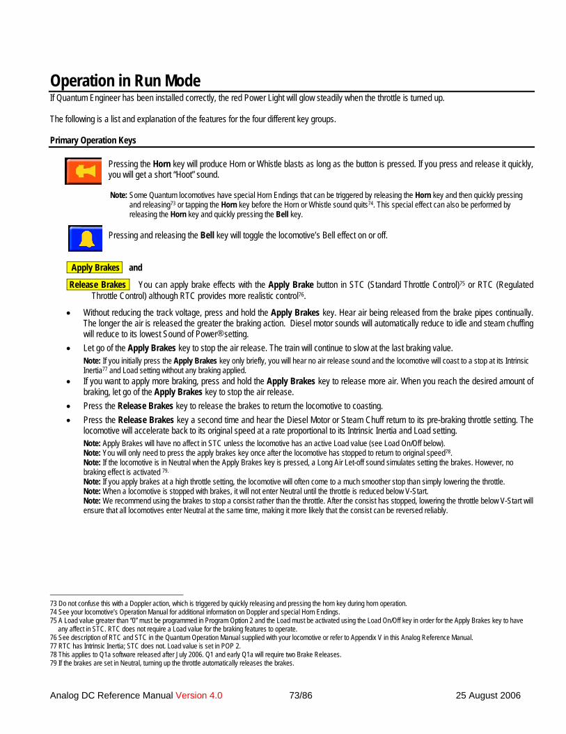
An
Operation in Run ModeIf Quantum Engineer has been installed correctly, the red Power Light will glow steadily when the throttle is turned up.
The following is a list and explanation of the features for the four different key groups.
Primary Operation Keys
Pressing the Horn key will produce Horn or Whistle blasts as long as the button is pressed. If you press and release it quickly,
73 D74 S75 A
a76 S77 R78 T79 I
a
you will get a short “Hoot” sound.
Note: Some Quantum locomotives have special Horn Endings that can be triggered by releasing the Horn key and then quickly pressingand releasing73 or tapping the Horn key before the Horn or Whistle sound quits74. This special effect can also be performed byreleasing the Horn key and quickly pressing the Bell key.
n
f
log DC Reference Manual Version 4.0 73/86 25 August 2006
Pressing and releasing the Bell key will toggle the locomotive’s Bell effect on or off.
Apply Brakes and
Release Brakes You can apply brake effects with the Apply Brake button in STC (Standard Throttle Control)75 or RTC (RegulatedThrottle Control) although RTC provides more realistic control76.
• Without reducing the track voltage, press and hold the Apply Brakes key. Hear air being released from the brake pipes continually.The longer the air is released the greater the braking action. Diesel motor sounds will automatically reduce to idle and steam chuffingwill reduce to its lowest Sound of Power® setting.
• Let go of the Apply Brakes key to stop the air release. The train will continue to slow at the last braking value.Note: If you initially press the Apply Brakes key only briefly, you will hear no air release sound and the locomotive will coast to a stop at its IntrinsicInertia77 and Load setting without any braking applied.
• If you want to apply more braking, press and hold the Apply Brakes key to release more air. When you reach the desired amount ofbraking, let go of the Apply Brakes key to stop the air release.
• Press the Release Brakes key to release the brakes to return the locomotive to coasting.• Press the Release Brakes key a second time and hear the Diesel Motor or Steam Chuff return to its pre-braking throttle setting. The
locomotive will accelerate back to its original speed at a rate proportional to its Intrinsic Inertia and Load setting.Note: Apply Brakes will have no affect in STC unless the locomotive has an active Load value (see Load On/Off below).Note: You will only need to press the apply brakes key once after the locomotive has stopped to return to original speed78.Note: If the locomotive is in Neutral when the Apply Brakes key is pressed, a Long Air Let-off sound simulates setting the brakes. However, nobraking effect is activated 79.
Note: If you apply brakes at a high throttle setting, the locomotive will often come to a much smoother stop than simply lowering the throttle.Note: When a locomotive is stopped with brakes, it will not enter Neutral until the throttle is reduced below V-Start.Note: We recommend using the brakes to stop a consist rather than the throttle. After the consist has stopped, lowering the throttle below V-Start willensure that all locomotives enter Neutral at the same time, making it more likely that the consist can be reversed reliably.
o not confuse this with a Doppler action, which is triggered by quickly releasing and pressing the horn key during horn operation.ee your locomotive’s Operation Manual for additional information on Doppler and special Horn Endings. Load value greater than “0” must be programmed in Program Option 2 and the Load must be activated using the Load On/Off key in order for the Apply Brakes key to havey affect in STC. RTC does not require a Load value for the braking features to operate.
ee description of RTC and STC in the Quantum Operation Manual supplied with your locomotive or refer to Appendix V in this Analog Reference Manual.TC has Intrinsic Inertia; STC does not. Load value is set in POP 2.his applies to Q1a software released after July 2006. Q1 and early Q1a will require two Brake Releases.the brakes are set in Neutral, turning up the throttle automatically releases the brakes.

Analog DC Reference Manual Version 4.0 74/86 25 August 2006
Locomotive Feature Keys
Load On/Off Once you enter the Load value into Programming Option #2 (POP 2) and return to Run Mode, you can toggle this Loadvalue on or off in Neutral with the Load On/Off key. When Load is off, the locomotive will accelerate or decelerate at its Intrinsic Inertiavalue.
Operation while in Neutral• Press the Load On/Off button once in Neutral to turn on the Load. You will hear a Long Air Let-off.• Double press the Load On/Off button in Neutral to turn off the Load. You will hear a coupler clink.Note: Locomotive labored sounds (Sound-of-Power™) are increased when Load is on and the locomotive is accelerating.
Operation while MovingWith RTC80 selected and the locomotive is moving in Forward or Reverse, pressing the Load On/Off button will apply or remove a “HeavyLoad” to the locomotive. This represents a train that would take over ten to fifteen minutes to accelerate to full speed or to coast to a completestop. You can apply “Heavy Load” as soon as you start moving or wait until you are up to speed.
• Press the Load On/Off button once in Forward or Reverse to turn on Heavy Load. Hear a single Horn or Whistle hoot.• Double press the Load On/Off button in Forward or Reverse to turn off Heavy Load. Hear a double Horn or Whistle hoot.Note: Heavy Load does not require you to program any Load values in POP 2.
Note: If you apply Air Brakes while in Heavy Load, the locomotive will return to operation using the programmed Load setting in POP 2.
Note: Be aware that once Heavy Load is turned on, the throttle will have little effect in changing the speed of the train. If you turn thethrottle up, you will hear very intense Sound of Power effects or if you turn the throttle down, you will hear very subdued Sound of Power81.You can use this feature to create heavy labored sounds while climbing a grade or reduced labored sounds while descending a grade withvery little change in the speed of the train.
Dynamic Brakes Many prototype diesel locomotives have dynamic brakes that cause the train to slow down by using the traction motors ingenerator mode. This helps dissipate the energy of a moving train by converting it to electrical power, which is then applied to a largeair-cooled resistor load in the locomotive.
• While the locomotive is operating at a steady speed, press the Dynamic Brakes key once to turn on the Dynamic Brakes. Hear theDiesel Motor reduce to notch 1 followed by the sound of the powerful diesel Cooling Fan starting up.
• Double press the Dynamic Brakes key to turn off the Dynamic Brakes. Hear the Dynamic Brake Cooling Fan shut off while the DieselMotor returns to its original notch and Sound-of-Power setting.
Note: If the Dynamic Brakes key is pressed for a steam locomotive, the Chuffing will reduce to a low level and return to its previoussetting when Dynamic Brakes are shut off. This makes steam locomotive behavior similar82 to diesels in a consist.
Note: In contrast to Air Brakes (F7), Dynamic Brakes do not increase the deceleration rate specified by the Load setting in POP 2. TheDynamic Brakes are only a sound effect and have no actual braking action83.
Note: The Dynamic Brake function automatically turns off when entering or leaving Neutral, or when the speed of the locomotive dropsbelow 7 smph84. The Dynamic Brakes cannot be turned on in Forward or Reverse unless the locomotive is traveling over 8 smph. DynamicBrakes will not turn on if the locomotive is accelerating.
Note: Dynamic Brakes can be turned on in Neutral if the locomotive is in Disconnect (see below under Locomotive State Keys).
Grade Crossing Prototype railroads use horn or whistle codes of long and short blasts for communication or warning signals. One of themost common is the code of two longs, a short and a long horn signal to warn of approaching a grade crossing. Although the Quantumoperator can perform these signals with the Horn button, we have made it even more convenient.
• Press the Grade Crossing key once to trigger the grade crossing warning signal. .
80 Load On/Off has no effect under STC.81 If you turn the throttle down too far, the train will slow quickly as the available power to the track falls below the level that is necessary for RTC to operate.82 It would be unrealistic for a steam locomotive to be working at full Sound-of-Power while Dynamic Brakes are being applied to other locomotives within the same consist.83 Prototype dynamic brakes are commonly used on down grades with the intention of maintaining a constant speed rather than stopping the train.84 Dynamic Brakes on prototype diesel locomotives are seldom used at low speeds where they are less effective.

Analog DC Reference Manual Version 4.0 75/86 25 August 2006
• If you press the Horn key during the Grade Crossing scenario, you will terminate this feature and take control of the Horn or Whistle.Note: Grade Crossing feature does not operate in Neutral.
Doppler You can trigger the Doppler effect by quickly interrupting the horn signal in the same way it is described in the Analog section ofyour Quantum Operation Manuals. Or you can use the Doppler Key dedicated to the Doppler effect.
• Start the Horn or Whistle by pressing the Horn key85 and hear the normal Horn or Whistle.• While still pressing the Horn key, press and release the Doppler key to hear the Doppler shift. A few seconds after the Horn key is
finally released the locomotive sounds return to normal 86.
Flanges Quantum provides automatic Squealing Brakes87 sounds as a locomotive slows to a stop. The operator can also control Squealingsounds for continuous and variable brake sounds for protracted stops or to simulate the sounds of wheel Flanges on curved track.
• Pressing the Flanges key when the locomotive is moving at any speed will manually activate Squealing sounds, and repeatedpressings while the Squealing sounds are occurring will continue the sounds uninterrupted.
Note: Flanges are a sound effect only and will not slow the locomotive.• The Flanges key can also be used to arm steam Cylinder Cocks when the locomotive is in Neutral. This eliminates the need to wait
for a full 25 seconds before the Cylinder Cocks arm.
Coupler Sounds There are two ways to use the Coupler Sounds effect key.
• As your locomotive is about to couple up to a string of cars, press the Coupler Sounds key to trigger the Coupler Crash sound. Usethe Coupler Sounds key again as the locomotive moves out to trigger the same sound as the slack is taken up in the cars88.
• Coupler Sounds have a different effect in Neutral. While stopped in Neutral in uncoupling position over an uncoupling magnet, pressthe Coupler Sounds key once to produce the sound of the lift bar and coupling pin being raised. This also Arms the uncouplingsound effect. Press the Coupler Sounds key again while pulling away from the cars (or remaining stationary in Neutral) to trigger thesound of the coupler knuckle opening and air-lines parting.
Smoke Your locomotive may be equipped with an automatic Smoke Unit, which may control the smoke differently in each of thedirectional states.
• Press the Smoke key once to turn on the automatic Smoke Unit.• Double press the Smoke key to turn off the automatic Smoke Unit. The Smoke Unit will be off in all directional states.Note: The Smoke Unit in your locomotive may be wired directly to the power pick-ups in which case it will not be controlled by QARCtechnology and pressing the Smoke button on the Quantum Engineer will have no effect.
85 If you do not turn on either Horn or Bell, the Doppler shift will still occur with the locomotive sounds, but will be less dramatic.86 If the bell was on, it will shut off prior to all sounds returning to normal.87 Squealing Brakes come on automatically when the speed is reduced from high-speed travel (over 40 smph) to less than 20 smph.88 The locomotive must actually be moving in order for this effect to occur.

Analog DC Reference Manual Version 4.0 76/86 25 August 2006
Automatic Features with “Take Control” OperationMany of the features that can be turned on or off by Quantum Engineer already have Automatic Control. The Quantum System allows theoperator to “Take Control” of certain automatic features by using their associated control keys. Once you “Take Control”, the features will nolonger have Automatic Control and you will control their operation and state with their key commands. Automatic and Take Control operationsare described in the table below.Quantum “Take Control” Operation
Automatic Operation Take ControlForward Reverse Neutral Key Operation
Steam Blower Hiss Off after 10seconds
Off after 10seconds
On after 10seconds
Blower/Fans Turns the Blower hiss sounds on or off.
Diesel Vents &Cooling Fans
Non-operating Non-operating On and off atrandom times
Blower/Fans Turns the Cooling Fans on or off.
Number BoardLights
On On On Number Boards Turns the Number Board Lights on or off.
Headlight On Dim Dim Headlightand
Dim Headlight
Headlight key turns Headlight on or off.Dim Headlight key will dim or brighten aHeadlight that is turned on.
Reverse Light Off On Off Reverse Light Turns the Reverse Light on or off.Hazard Lights Strobing Dim Dim Hazard Lights
andStrobe Hazard
Hazard Light key turns the Hazard Lightson or off. Strobe Hazard key selectsHazard light to strobe or become steady-on.
Cab Lights Off after 15seconds
Off after 15seconds
On after 10seconds
Cab Lights Turns the Cab Lights on or off.
Steam CylinderCocks
If armed, plays11 times, or untilloco exceeds 8
smph.
If armed, plays11 times, or untilloco exceeds 8
smph.
Auto Arms after 25seconds.
Flanges Arms steam Cylinder Cocks in Neutral.
Automatic operation is restored if the power is shut down and reapplied or if the Start Up key is pressed in Neutral (see the description of StartUp on page 77).Note: If your locomotive has an optional Hazard Light, the Headlight may not be dimmable.
• The following are all Take Control features that can be operated by the different Quantum Engineer keys.
Number Board Lights This key turns the Number Board lights on or off on specially equipped diesels.
• Press the Number Boards key once to turn on and take control of the Number Board Lights.• Double press the Number Boards key to turn off and take control of the Number Board Lights.
Headlight ‘
• Press the Headlight key once to turn on and take control of the Headlight. The Headlight will be on in all directional states.• Double press the Headlight key to turn off and take control of the Headlight. The Headlight will be off in all directional states.
Dim Headlight • Press the Dim Headlight key once to dim the Headlight and Take Control of the Directional Headlight brightness.• Double press the Dim Headlight key to brighten the headlight and take control of the Headlight.• Note: If the Headlight has been turned off with the Headlight key, the Dim Headlight key will not have a noticeable effect. However,
if the Headlight is turned on at a later time, it will come on with the dim setting set by the Dim Headlight key.
Reverse Light ‘

Analog DC Reference Manual Version 4.0 77/86 25 August 2006
• Press the Reverse Light key once to turn on the Reverse Light and Take Control of the Reverse Light. The Reverse Light will be onin all directional states.
• Double press the Reverse Light key to turn off and take control of the Reverse Light. The Reverse Light will be off in all directionalstates.
Hazard Lights Hazard Lights can be a Mars Light, Over-Head Blinking Lights, or Ditch Lights.
• Press the Hazard Lights key once to turn on and take control of the Hazard Lights. The Hazard Light will be on in all directionalstates.
• Double press the Hazard Lights key to turn off and take control of the Hazard Lights. The Hazard Lights will be off in all directionalstates.
• Note: Mars Light and Ditch Lights are part of the automatic lighting system. Overhead Blinking Lights are on in all directional states.
Strobe Hazard Hazard Lights can either be steadily-on or be strobed. The Mars Light strobe gives the effect of a moving beam of light,the Over-Head Light strobe is a steady repetitive blinking, and Ditch Light strobe blinks back and forth between the right and left lights.
• Press the Strobe Hazard key once to turn on the strobe effect and take control of the Hazard Lights.• Double press the Strobe Hazard key to turn off the strobe effect and take control of the Hazard Lights.• Note: If Hazard Lights have been turned off with the Hazard Lights key, the Strobe Hazard key will not have a noticeable effect.
However, if the Hazard Lights are turned on at a later time, they will come on at the strobe setting set by the Strobe Hazard key.
Cab Lights This key turns the Cab Lights on or off on specially equipped locomotives.
• Press the Cab Lights key once to turn on and take control of the Cab Lights.• Double press the Cab Lights key to turn off and take control of the Cab Lights.
Blower/Fans This key turns the steam Blower or diesel Cooling Fans on or off.
• Press the Blower/Fans key once to turn on and take control of Blower or Cooling Fans operation.• Double press the Blower/Fans key to turn off and take control of Blower or Cooling Fans operation.
Locomotive State Keys
Disconnect/Standby Disconnect will disable the locomotive’s electric motor drive circuit to allow the throttle to be changed without thelocomotive moving. In Disconnect, the operator can increase the throttle on a stationary locomotive to rev the Diesel Motor or vent steam in asteam locomotive.
Standby places the locomotive in a special idle state with subdued sounds where it will not respond to throttle or most of the feature keys89.Standby is ideal for leaving your locomotives running on a siding while you operate other locomotives.
• Press the Disconnect/Standby key once in Neutral to enter Disconnect.• To leave Disconnect:
• Press the Start Up key to regain normal operation.• Or press the Disconnect/Standby key again to enter Standby.• Or press the Shut Down key to enter Total Shut Down.
• To leave Standby:• Press the Start Up key to enter normal operation.• Or press the Shut Down key to enter Total Shut Down.
89 The four exceptions are the F6 Start Up key, the Mute Key, the Shut Down key and the Status Key.

Analog DC Reference Manual Version 4.0 78/86 25 August 2006
Note: You can turn on diesel Dynamic Brakes in Disconnect to create Sound–of-Power as the throttle is moved up and down. Engineerson prototype diesels use the dynamic brakes to load the diesel motor-generator to test its output and efficiency while the locomotiveremains stationary.Note: If power is turned off during either the Disconnect or Standby procedures, the locomotive will remember the last command and willpower up in the same stage.Note: If Start Up is initiated during any of the above procedures, the locomotive will immediately return to normal operation.Note: Neither the Horn nor the Bell key will operate in Standby or Shut Down. Analog Programming is disabled in Disconnect andStandby.
Shut Down Shut Down allows the operator to take the locomotive “off line” (turn off sounds, lights, ignore throttle settings and featurecommands90) independent of the operating session; that is, the locomotive will still be “off line” when power is reapplied for the nextoperating session.
• Press the Shut Down key once to produce a Rapid Shut Down. Rapid Shut Down will shut the locomotive off in a few seconds.• Double press the Shut Down key to produce an Extended Shut Down scenario. Extended Shut Down will shut the locomotive down
over thirty seconds with progressive sound and light effects. The Extended Shut Down for diesels and steam locomotives is asfollows:
Diesel Extended Shut Down: After double pressing the Shut Down key, hear a Long Air Let-off, followed by Directional Lighting turningoff (if on). In a few seconds, the Air Pumps shut off, followed by the Number Boards and the sounds of the Cooling Fans shutting off, thelouvers closing, the Diesel Motor shutting down and finally, the Cab Lights shutting off. After a short time, you will hear the engineer’s dooropen and then shut.
Steam Extended Shut Down: After double pressing the Shut Down key, you will hear a Long Air Let-off, followed by Directional lightingturning off (if on). In a few seconds, the Air Pumps will turn off, followed by the sounds of Pop Off operating for about ten seconds followedby a hiss sound that gradually trails off to silence.• To leave the Shut Down state, press the Start Up key.
Note: If power is turned off during a Shut Down procedure, the locomotive will be in Shut Down when power is reapplied.Note: If the Start Up key is pressed during a Shut Down procedure, Shut Down is aborted and the locomotive returns to normal operation.Note: Except for a few extra sound effects for Extended Shut Down, the shutting down of lighting and sound effects still occur during RapidShut Down but happen more quickly.Note: You cannot shut down a locomotive while it is moving. There is no response if you press the Shut Down key in Forward or Reverse.Note: Any locomotive on the powered track while you press the Shut Down key will go into Shut Down
Start Up If your locomotive is in Disconnect, Standby or Shut Down, you can return your locomotive to normal operation by pressing theStart Up key.
Start Up will be different for each stage of Shut Down, but all will start up with a Long Air Let-off and will enter normal operation.• Start Up from Disconnect: Press the Start Up key in Disconnect and the locomotive will produce a Long Air Let-off then enter
normal operation.• Start Up from Standby: If you double press the Start Up key in Standby, the locomotive will produce a Long Air Let-off, the
Directional Lighting will turn on and then the locomotive will enter normal operation.• Start Up from Shut Down:
• Press the Start Up key once to produce Rapid Start Up.• Double press the Start Up key to produce an Extended Start Up scenario. The Extended Start Up for diesels and steam
locomotives is as follows:Diesel Extended Start Up: If you double press the Start Up key, the diesel locomotive will produce a Long Air Let-off. After a few seconds, youwill hear the engineer’s door opening and closing, followed by the vents opening, the Diesel Motor starting up, the Air Pumps starting up, andthe locomotive entering normal operation.
90 In Total Shut Down, the locomotive will not respond to throttle or commands. The two exceptions are the Start Up Key and the Status Key. If your locomotive is equipped with
the Magnetic Wand option, this can be used to perform a Total Shut Down (see your Quantum Operation Manual).

Analog DC Reference Manual Version 4.0 79/86 25 August 2006
Steam Extended Start Up: If you double press the Start Up key in Shut Down, the steam locomotive will produce a Long Air Let-off, theDynamo will rev up and the Directional Lighting will turn on, followed by the Air Pumps starting up, the steam Blower turning on, the steamCylinder Cocks arming and then the locomotive will enter normal operation.Note: If your locomotive has been Deselected and Shut Down using a Magnetic Wand, it must first be selected by pressing the Start Up key for3 seconds followed by again pressing the Start Up key to start the locomotive.
Note: Whenever a Start Up command is sent to a selected locomotive, regardless of whether the locomotive is in Shut Down or operatingnormally, the Quantum System will automatically restore all Automatic Controls and re-arm Cylinder Cocks on steam locomotives.
Status Report Quantum provides verbal information about the locomotive’s current operating state when the locomotive is stopped or thelocomotive’s current speed in scale miles per hour when the locomotive is moving.
• Press the Status key when the locomotive is stopped in Neutral. If the locomotive is in Disconnect /Standby /Shut Down it will say so.Otherwise the locomotive’s Helper type (if not Normal) will be announced, followed by Load level, followed by Load on/off status (ifLoad not equal to zero), followed by type of Throttle Mode (Regulated or Standard).
• Press the Status key while the locomotive is moving. The locomotive will verbally report its speed in scale miles per hour.Note: When Status Report is activated, the locomotive’s sounds will reduce to one half their current volume settings during the verbalreport and then return to normal volume when the report has ended.
Star Pad Keys During Normal Operation Volume and
Volume Locomotive System Volume can be changed91 anytime the locomotive is operating (except in Shut Down).
• Press the Volume key to increase the System Volume level.
• Press the Volume key to decrease the System Volume level.Each time either Volume key is pressed and released, the volume changes by 2 db. Or press and hold either Volume key to automatically stepup or down through the volume levels one by one; release the key when the desired volume is reached.Note: System Volume cannot be changed while a locomotive is in Shut Down.
Mute The Quantum System allows you to reduce the System Volume to a lower level or increase it back to its original setting using theMute key. This is useful when you need to lower the sound to engage in a conversation or to answer the phone. The Mute featurechanges the sound gradually over a second or two, which allows the sound to increase or decrease realistically as the locomotiveapproaches or recedes from the observer.
• Press the Mute key once to gradually reduce the volume to the Mute level.• Double press the Mute key to gradually restore the locomotive sounds to their normal level.
Note: Mute state is not maintained if power is turned off and back on; the locomotive will return to full System Volume setting.
STC and
RTC Use these keys in Neutral to select Throttle Mode. Quantum has two types of throttle control as described in the Quantum OperationManual that came with the locomotive. Regulated Throttle Control (RTC) has motor control capability that allows the locomotive tobehave as though it has massive inertia. Locomotives under Standard Throttle Control (STC) respond quickly to changes in throttle orloading. The default is RTC.
• Press the STC key to select Standard Throttle Control. Hear the locomotive respond with “Standard”.• Press the RTC key to select Regulated Throttle Control. Hear the locomotive respond with “Regulated”.
Regulated Throttle is preferred under normal operation. However, STC is preferred when putting locomotives away or when uncoupling. 91 If your locomotive is equipped with Magnetic Wand option, the System Volume can also be increased or decreased, using the wand, in any state. See your Quantum Operation
Manual.

Analog DC Reference Manual Version 4.0 80/86 25 August 2006
Programming with Star Pad KeysThe Quantum Engineer Controller makes Analog programming of your Quantum locomotive with QARC technology very simple. Allprogramming is done using the Star Pad keys. When a key’s programming function is different from its normal function, the programmingfunction is indicated in gray italics.
Entering Program Mode
Prgm Press and hold the Prgm key prior to turning up the throttle to where the locomotive sounds come on. Continue to hold the Prgmbutton until you hear “Enter Programming”. The locomotive will then respond with “Option One – System Volume”.
Note: You cannot use the Prgm key to enter programming on earlier Quantum locomotives that do not have QARC technology.Note: Once you have entered Programming, the Prgm key has no effect.Note: When in Programming Mode, the red power light on the Quantum Engineer blinks on and off continuously92.Note: When in Programming Mode, the locomotive’s Directional Lighting alternately blinks between the Headlight and the Reverse Light.
Scrolling through the Program Options Next and
Prev Use the Next and Prev keys on the Star Pad to move easily through the Program Options (POP’s). The Program Option numbers andnames are listed in a table in your Quantum Locomotive Operation Manual under Analog Programming.
• Press the Next key once to move to the next POP. The locomotive will announce the next POP number and name. Or press and holdthe Next key to automatically step up through the POP’s one by one and then release the key when the desired POP is reached. Thelocomotive will verbally count up through each POP number while the key is pressed and then will announce the POP name when theNext key is released.
• Press the Prev key once to move to the previous POP. The locomotive will announce the previous POP number and name. Or pressand hold the Prev key to automatically step backwards through the POP’s one by one and then release the key when the desiredPOP number is reached. The locomotive will verbally count down through each POP number while the key is pressed and then willannounce the POP name when the Prev key is released.
Entering a Program Option and Making Changes
Volume and
Volume The Up Volume and Down Volume level keys can be used to enter and change POP values.• Press either the Volume or Volume key once to enter the POP. Entering a POP does not make any changes. The locomotive
will announce the current setting for that option. For any volume option, you will hear “Volume equals X” (where “X” is its currentvolume level setting). After a moment, you will hear the sound playing at its current volume93.
• After the announcement of the current value, press the Volume or the Volume key to increase or decrease the option settingby one level. Or press and hold the Volume or Volume key to automatically step up or down through the level settings one byone and then release the key when the desired level is reached.
Note: Most of the POP’s are for features that have different level settings. For instance, many POP’s are used to increase or decreasevolume levels of the different sound effects while POP 2 is used to increase or decrease the Load setting.For volume settings, the Volume will increase the volume level and the Volume will decrease the volume level. Volume will changeby 2 db for each level change. These two buttons also increase or decrease the Load level in POP 2. For POP’s with level settings, you willhear the level value spoken out.
92 If programming has been entered correctly, the locomotive directional lights should also be blinking.93 Setting any volume in Analog will also apply to DCC and vice-versa.
Analog DC Reference Manual Version 4.0 81/86 25 August 2006
For other POP’s, the Volume and Volume keys scroll through the possible settings.
Some POP’s simply go through some ordered procedure such as V-Start, V-Max, Reset, and About. These POP’s do not distinguishbetween the Volume and Volume keys. These POP’s will advance through their procedures one step at a time when either theVolume or Volume key is pressed.
Note: Press the Next or the Prev keys any time to move to the next or previous POP. Or press and hold the Next or the Prev keys toautomatically step through the POP’s.
Leaving Programming
• Exit Program Mode anytime you want by turning the power off and back on again.Note: You can leave Programming anytime you want, regardless of which part of Programming you are in. If you have made a change,that change will be retained when you exit.

Analog DC Reference Manual Version 4.0 82/86 25 August 2006
Trouble Shooting Quantum EngineerMy loco does not respond to any or someQuantum Engineer keys.
Your locomotive may not have Quantum Analog Remote Control (QARC) technology.Or you may have shut your locomotive down with the Shut Down key or Magnetic Wand. If so,
press the Start Up key for three seconds.Or you may have forgotten that a double press turns off some features and a single press turns
them on.Or some features may not be included in your model.
I can turn on a feature with a single press butcannot turn it off with a double press. Thefeature stays in the on state.
You are probably doing the double press too slowly. Double-pressing is similar to double-clinkinga computer mouse key. It is very rapid. If you are pressing the key and waiting too long beforepressing it again, you are simply sending the “on” command twice.
My locomotive is completely dead. Nosounds, not even an air release when poweris first applied.
Try resetting the loco with its jumper or magnetic wand (see your Quantum Operation Manual).Or, if your locomotive was being operated in DCC and power was suddenly removed while
moving, the loco may still be waiting for a DCC signal. Place the locomotive on DCC track,activate, stop loco and turn off power.
Or you may have pickup problems in your loco or an area of dead track.My loco makes sounds but will not respond tothe throttle.
You may have applied brakes to stop your locomotive. Either reduce the throttle below V-Start orpress the Release Brake key two times.
Or your locomotive is in Disconnect or Standby. Press the Start Up key.I cannot get my locomotives to program. Older Quantum locomotives cannot be programmed using the Quantum Engineer Program keys.
Or you may not be holding the Prgm key down before turning on the power,Or you may not be holding it down long enough after turning on the power.
Pressing the Apply Brake key does notseem to have much affect at high speeds.
Set V-Max to a higher value (about 85% of full throttle voltage).Or you are in STC and no Load is turned on.
Sometimes in Neutral, Horn or Bell keyshave no affect.
When entering Neutral, you must wait for the long air release before the Horn and Bell buttonswill operate.
My Quantum Engineer will not sendcommands when keys are pressed. I do nothear any clicking sounds like I normally do.
Turn power off and back on again to reset the Quantum Engineer to normal operation.
When I press the Apply Brake key, thelocomotive will not slow down for a long timeand then when it does, it stops suddenly.
If you press the Apply Brake once briefly, the locomotive will enter coasting and slowly decelerateto a stop. However, if you have set V-Max too low, it will take some time before the RTCalgorithm applies an internal motor voltage below V-Max. The effect is to “hang” thelocomotive at a constant high speed for some time before it starts to slow down. Someoperators will apply more and more braking to slow the locomotive when it is in this state,which causes the locomotive to slow rapidly when the internal voltage drops below V-Max. Tominimize this problem, set V-Max close to your maximum throttle position.
After I apply Air Brakes and the locomotive isstopped, changing the direction switch blowsthe Whistle/Horn instead of changingdirection.
After stopping with the Air Brakes, you must turn the throttle down until you hear a Short Air Let-off to enter Neutral and then change direction with the direction switch. If you leave thethrottle turned up above V-Start, you are not in Neutral.

Analog DC Refe
Quantum Engineer FeaturesQuantum Engineer will operate the following features in locomotives equipped withQuantum Analog Remote Control (QARC) technology:
Horn Grade Crossing Horn SignalBell Smoke On/OffApply Air Brakes Headlight On/Off & DimRelease Air Brakes Reverse Light On/OffLoco Shut Down Number Board Lights On/OffLoco Start Up Hazard Lights On/Off & StrobeStandby Idle Cab Lights On/OffFlange Squeal Blower or Fans On/OffSquealing Brakes Dynamic Brakes On/OffDoppler Shift Motor DisconnectCoupler Lift Bar and Pin MuteCoupler Opening Sounds Verbal Speedometer ReadoutCoupler Crash Locomotive Status ReportLoad On/Off Easy Quantum ProgrammingHeavy Load On/Off Prev & Next Program SteppingSystem Volume in Run Mode Steam Cylinder Cocks
Regulated (RTC) & Standard Throttle (STC) Selection
rence Manual Version 4.0 83/86 25 August 2006

Analog DC Reference Manual Version 4.0 84/86 25 August 2006
Appendix IX: Software ChangesQuantum Q1 Analog Changes and ImprovementsAnalog Changes and Improvements in Q1
Over the last four years many improvements have been made to the Q1 system, which are incorporated into the Q1a product. If you havepurchased a recent factory installed Q1 System, all these improvements will have been included. If you have an early model, less of thesefeatures will be included. In either case, the addition of the Q1a upgrade to your locomotive will allow you to maintain the last softwareimprovements through future downloads from the QSI website. Except for the initial modest investment in the QSI QICKit that allows simpleupgrading of the software from our website, all future upgrades to the Q1a system are at no cost.
The following is a list of all improvements made to the Q1 system that are currently included in Q1a:
1. Improved immunity to sounds shutting off after minutes of operation to prevent sounds intermittently going off the air after minutes ofoperation. 4 September 2002.
2. Programming Option advance method improved to using track polarity rather than variations in track voltage. 24 September 2002.3. Regulated Throttle Control/Standard Throttle Control programmed in POP 10. RTC was pervious controlled by load setting in POP 2.
With this change load settings can also apply to STC and RTC can be used with zero load setting. 24 September 2002. RTCimproved on 15 April 03, 31 January 2003, 28 April 2004, 22 December 2004, 18 February 2004, 18 March 2005, and 8 April2005.
4. Separate Short Hoot sound added. 24 September 2002.5. High Voltage Circuit Breaker added, which prevents damage to the Quantum system and motors from some power packs high throttle
settings. 24 September 2002.6. Labored Drift/Chuff sounds added to steam and labored motor sounds added to diesels under load (Sound-of-Power™). 24
September 2002.7. Improved V-Start Operation. 24 September 2002.8. Synchronized steam loco headlight operation to dynamo start up. 24 September 2002.9. Motor Volume setting added, POP 15. 15 April 2003.10. Fan Volume setting added, POP 16. 15 April 2003.11. Diesel Cooling Fan Volume setting improved. POP 16. 4 August 200312. Steam Blower Volume setting added. POP 16. 4 August 200313. Diesel Turbo Volume setting added. POP 17. 4 August 200314. Improved horn/whistle operation by allowing user activation of a short “hoot” to follow a long horn or whistle sound. 25 November
2003.15. Added QARC Technology and all associated features to support Quantum Engineer operation. 28 April 2004. Improved 19 July
2004. Air brakes improved 14 Aug 2004 and 25 Oct 2004.16. Shut Down and Start Up Effects Added for QARC; Disconnect/Low Idle/Total Shut Down and the choice of Extended or Normal
Shutdown and Start Up. 28 April 2004.17. Doppler pitch shift increments increased to provide a smoother continuous transition. 28 April 2004.18. Improved mallet (articulated chuff) to sound more realistic during start up. 28 April 2004.19. Added horn signal when leaving Neutral: If the operator waited past the transition setting before changing polarity and the horn comes
on, then when throttle is increased, an additional short hoot sounds if the locomotive is set to forward or two additional short hoots ifthe locomotive is set to go in reverse. This results in two horn sounds if the locomotive is going forward or three if the locomotive goesin reverse, which are standard prototype horn signals. 14 July 2004.
20. Playable horn/whistle endings added: Alternate horn or whistle is played if the horn button is tapped after releasing horn button. Onlyavailable on those models that have alternate endings available. 10 September 2004.
21. Ditch light function added with alternating lights when horn is blown. 10 September 2004.22. Low Idle improved for diesel locomotives by turning off turbo. 14 October 2004.23. Diesel turbo “crackle” sound eliminated. 20 October 2004. Turbo Sound improved, 25 October 2004.24. New automatic V-Start procedure implemented that compensates for voltage drop in lower quality power packs. 25 October 2004.25. V-Start routine improved by using the initial track voltage, not the end voltage at finish of routine, as the V-Start value. 4 November
2004.

Analog DC Reference Manual Version 4.0 85/86 25 August 2006
26. Added software to prevent intermittent direction change with some power packs where the locomotive would loose power and theprocessor would restart. 11 November 2004.
27. Improvements for low geared diesel switchers include arming brake sounds at >20 smph and trigger < 10 smph. 22 November 2004.28. Ditch Lights Strobe Hold Time setting added to DCC, which also applies to Analog operation. 12 January 2005.29. Improved RTC to prevent severe locomotive lurch that occurred on some models. 18 January 2005.30. Fixed problem with inconsistent memory writes/reads of Long Term Memory (LTM). This problem would sometimes erase or change
settings and applied only to some locomotives with reed switches. 18 February 2005.31. Improved consisting when operating under RTC. The problem: when consisting two or more locomotives together, the locomotives
could surge together and apart with a period of 2-3 seconds at certain speeds. 18 March 2005.32. Almost all individual sounds re-scaled to allow the individual sounds to still be heard as system volume is reduced to very low levels.
18 March 2005. Steam Blower hiss re-scaled on 11 April 2005.33. Improved RTC to ensure locomotive comes to a complete stop when air brakes are applied under QARC. 8 April 2005. Improved 9
May 2005.34. New GE pumps and dynamic brakes added. 10 May 2005.35. Improved steam chuff synchronization. 12 July 2005.
Minor Fixes and Improvements
In addition to changes listed above from 4 September 2002 though current software releases, many minor improvements and fixes havebeen made to the Quantum 1 System under DC and DCC to numerous to list here. Dates where fixes were implemented are as follows:
4 September 2002, 24 September 2002, 15 April 2003, 6 July 2003, 4 August 2003, 7 October 2003, 9 October 2003,10 October 2003, 27 October 2003, 29 October 2003, 31 October 2003, 25 November 2003, 31 January 2004,16 February 2004, 28 April 2004, 14 July 2004, 19 July 2004, 10 September 2004, 14 October 2004, 20 October 2004,11 November 2004, 18 March 2005, 8 April 2005
A user can determine the date of his software release under DC or DCC programming to determine which features or improvements areincluded from the above lists.

Analog DC Reference Manual Version 4.0 86/86 25 August 2006
QSIndustries, Inc. Software License Agreement1. Grant of License: QSIndustries, Inc. grants you, the owner, the right to use the software that is included with your Quantum system only with the locomotive that you purchased.2. Copyright: The software is owned by QSIndustries, Inc. and is protected by United States copyright laws and international treaty provisions. Therefore, neither you nor anyone else may copy the software.Proprietary Rights and ObligationsThe structure and organization of the Software/Firmware are the valuable properties of QSIndustries, Inc. You will not make or have made, or permit to be made, any copies of the Hardware, Software/Firmware, code, or any portions thereof.You are not to modify, adapt, translate, reverse engineer, de-compile, disassemble or create derivative works based on the Hardware or Software/Firmware. Trademarks shall be used in accordance with accepted trademark practice,including identification of trademark owner’s name. The Quantum Hardware, Software and Firmware are covered by U.S. Patent No. 4,914,431; 5,184,048; 5,267,318; 5,394,068; 5,448,142; 5,633,985; 5,832,431; 5,896,017; 5,940,005; andUS and Foreign patents pending.No Other RightsQSIndustries, Inc. retains ownership of the Quantum Hardware design and operating Software/Firmware code. Except as stated above, this agreement does not grant you any rights to intellectual property rights to the Quantum Software,Firmware or Hardware. The use of any trademarks as herein authorized does not give you any rights of ownership in that trademark. © 2006 All rights reserved. Printed in USA. Information in this publication supersedes that in all previous published material. The contents and the product it describes are subject to change without notice. QSI is a registered trademark ofQSIndustries, Inc. Quantum, Quantum System, Sound-of-Power, Scale Sound, Regulated Throttle Control, Quantum Inertial Control, Legacy System, ProPower, Quantum Air Brakes, QARC, are trademarks of QSIndustries, Inc. MRC is atrademark of Model Rectifier Corporation. All other trademarks are the property of their respective holders. QSI makes no representations or warranties with respect to this publication. In no event shall QSIndustries, Inc., be liable for anydamages, direct or incidental, arising out of or related to the use of this publication. Quantum Q1a Analog Ref Manual Ver 4 F(12)G(4)J(3) 8/06
QSIndustries, Inc.Beaverton, OR