
QCEC - Teledyne ISCO
112
QCEC “Dependability Defined” All-Season QLS Refrigerated Wastewater Samplers Optima, Premium and Dual Models Composite and Sequential Operations and Maintenance Manual Rev. A, February 2018 Part Number: 69-2303-212 4700 Superior Street • Lincoln, NE 68504 (402) 464-0231 • (800) 228-4373 www.teledyneisco.com • [email protected]
Transcript of QCEC - Teledyne ISCO

QCEC “Dependability Defined”
All-Season QLS Refrigerated Wastewater Samplers Optima, Premium and Dual Models
Composite and Sequential
Operations and Maintenance Manual Rev. A, February 2018
Part Number: 69-2303-212
4700 Superior Street • Lincoln, NE 68504 (402) 464-0231 • (800) 228-4373
www.teledyneisco.com • [email protected]


August 2017
TO: Purchaser of QCEC Brand Products FROM: Teledyne ISCO We hope that you find this recent product purchase meets your needs. We wanted to update you that the QCEC product you purchased is now manufactured by Teledyne ISCO and is backed by Teledyne ISCO’s commitment to quality products and exceptional customer service. Teledyne Isco, a world leader in automatic water sampling and open channel flow monitoring products, acquired in late April 2017 the QCEC line of water & wastewater automatic samplers and flowmeters. With the addition of this sampling vacuum pump technology, we are able to offer a broader sampler product offering to meet customers’ needs. Teledyne Isco has been in business for over 50 years manufacturing a wide range of products for professionals working in water pollution monitoring and abatement, engineers and managers involved with wastewater process control, and scientists involved in field and laboratory work. We take pride in the fact that the products we produce are used by our customers to improve the quality of life on Earth. We offer all our customers responsive, competent, and excellent service and support. Our customers are the most important part of our business, and we work tirelessly to ensure your complete satisfaction. Provided below are key contact information so that you can reach us at your convenience. Water & Wastewater Product Support: Telephone (402) 853-5350 Toll Free (USA) (866) 298-6174 Email [email protected] Teledyne ISCO 4700 Superior Street PO Box 82531 Lincoln, NE 68501 Telephone (402) 464-0231 Fax (402) 464-0318 Toll Free (USA) (800) 228-4373 Email information request [email protected] Website www.teledyneisco.com


Before returning any instrument for repair, please call, fax, or e-mail the Teledyne Isco ServiceDepartment for instructions. Many problems can often be diagnosed and corrected over thephone, or by e-mail, without returning the instrument to the factory.
Instruments needing factory repair should be packed carefully, and shipped to the attention ofthe service department. Small, non-fragile items can be sent by insured parcel post. PLEASEBE SURE TO ENCLOSE A NOTE EXPLAINING THE PROBLEM.
Shipping Address: Teledyne Isco - Attention Repair Service4700 Superior StreetLincoln, NE 68504 USA
Mailing Address: Teledyne IscoPO Box 82531Lincoln, NE 68501 USA
Phone: Repair service: (800) 775-2965 (lab instruments)(866) 298-6174 (samplers & flow meters)
Sales & General Information: (800) 228-4373 (USA & Canada)Fax: (402) 465-3001Email: [email protected]
January 10, 2017 P/N 60-1002-041
Teledyne Isco Two Year Limited Factory Service Warranty*This warranty exclusively covers Teledyne Iscoinstruments, providing a two-year limited warrantycovering parts and labor.Any instrument that fails during the warranty period due tofaulty parts or workmanship will be repaired at the factoryat no charge to the customer. Teledyne Isco’s exclusiveliability is limited to repair or replacement of defectiveinstruments. Teledyne Isco is not liable for consequentialdamages.Teledyne Isco will pay surface transportation charges bothways within the 48 contiguous United States if theinstrument proves to be defective within 30 days ofshipment. Throughout the remainder of the warranty period,the customer will pay to return the instrument to TeledyneIsco, and Teledyne Isco will pay surface transportation toreturn the repaired instrument to the customer. TeledyneIsco will not pay air freight or customer’s packing andcrating charges. This warranty does not cover loss, damage,or defects resulting from transportation between thecustomer’s facility and the repair facility.
The warranty for any instrument is the one in effect on dateof shipment. The warranty period begins on the shippingdate, unless Teledyne Isco agrees in writing to a differentdate.Excluded from this warranty are normal wear; expendableitems such as desiccant, pH sensors, charts, ribbon, lamps,tubing, and glassware; fittings and wetted parts of valves;check valves, pistons, piston seals, wash seals, cylinders,pulse damper, diaphragms, inlet lines and filter elements,and damage due to corrosion, misuse, accident, or lack ofproper maintenance. This warranty does not cover productsnot sold under the Teledyne Isco trademark or for which anyother warranty is specifically stated.No item may be returned for warranty service without areturn material authorization number issued by TeledyneIsco.This warranty is expressly in lieu of all other warrantiesand obligations and Teledyne Isco specifically disclaimsany warranty of merchantability or fitness for aparticular purpose.The warrantor is Teledyne Isco, 4700 Superior, Lincoln, NE68504, U.S.A.
* This warranty applies to the USA and countries where Teledyne Isco does not have an authorized dealer.Customers in countries outside the USA, where Teledyne Isco has an authorized dealer, should contact theirTeledyne Isco dealer for warranty service.

All-Season QLS Refrigerated Wastewater Samplers
April 25, 2016 v5A page 3
Table of Contents
Warranty ................................................................................................................................................................................. 2
Table of Contents ............................................................................................................................................................ 3
List of Illustrations .......................................................................................................................................................... 6
List of Tables ...................................................................................................................................................................... 6
Configuration Quick Start........................................................................................................................................... 7
Composite Sample Storage ................................................................................................................................ 9
Sequential Sample Storage ............................................................................................................................. 10
Operation Quick Start ............................................................................................................................................... 12
Chapter 1: Introduction ........................................................................................................................................... 13
1.1: Revision Notes ........................................................................................................................................... 13
1.2: Physical Description ................................................................................................................................ 15
1.2.1: Temperature Control System ................................................................................................ 15
1.2.2: Sample Collection Systems .................................................................................................... 15
1.2.3: Sample Storage Systems ......................................................................................................... 16
1.2.4: Sampling Control System......................................................................................................... 16
1.2.4.1: User Interface Panel ....................................................................................................... 17
1.2.4.2: Inputs and Outputs ......................................................................................................... 17
1.3: Sampling Programs ................................................................................................................................. 18
Chapter 2: Installation .............................................................................................................................................. 19
2.1: Positioning Considerations ................................................................................................................. 19
2.1.1: Hydrogen Sulfide Exposure ..................................................................................................... 19
2.2: Sampling Line Connection ................................................................................................................. 20
2.3: Velocity Valve Adjustment.................................................................................................................. 20
2.4: Field I/O Connections .......................................................................................................................... 21
2.4.1: Flow Inputs ......................................................................................................................................... 21
2.4.2: Relay Outputs .................................................................................................................................. 22
2.4.3: Float Input .......................................................................................................................................... 22
Chapter 3: User Interface Panel ....................................................................................................................... 23
3.1: Menu System ............................................................................................................................................... 24
3.2: Administration Menu .............................................................................................................................. 26
3.2.1: Administration Password ........................................................................................................... 26
3.2.2: Clock Settings .................................................................................................................................. 28
3.2.3: LCD Brightness ................................................................................................................................ 29
3.2.4: Archival Data Administration ................................................................................................. 30
3.2.5: Set ID Number ................................................................................................................................. 31
3.2.6: Set Volumetric Units ................................................................................................................... 31
Chapter 4: Sampling Program Configuration ............................................................................................ 32
4.1: Program Selection ................................................................................................................................... 32
4.2: Program Configuration Groups ....................................................................................................... 33
4.3: Sampling Cycle Settings ...................................................................................................................... 34
4.3.1: Pre-Sampling Purge Duration ................................................................................................ 34
4.3.2: Sample Size ....................................................................................................................................... 35
4.3.3: Post-Sampling Purge Duration .............................................................................................. 35
4.3.4: Line Conditioning Rinses .......................................................................................................... 36
4.3.5: Incomplete Sample Recycling ................................................................................................ 37
All-Season QLS Refrigerated Wastewater Samplers
April 25, 2016 v5A page 4
4.3.6: Consecutive Sampling ................................................................................................................. 37
4.4: Sampling Intervals .................................................................................................................................... 38
4.4.1: Timed Interval Sampling ........................................................................................................... 39
4.4.1.1: Fixed Length Time Intervals ...................................................................................... 39
4.4.1.2: Variable Length Time Intervals ................................................................................ 40
4.4.2: Flow Interval Sampling ............................................................................................................... 41
4.4.2.1: Analog Flow Input............................................................................................................. 42
4.4.2.1.1: Fixed Volume Flow Intervals ............................................................................. 43
4.4.2.1.2: Variable Volume Flow Intervals....................................................................... 43
4.4.2.2: Pulsing Flow Input ............................................................................................................ 44
4.4.2.2.1: Fixed Pulses Flow Intervals ................................................................................ 44
4.4.2.2.2: Variable Pulses Flow Intervals ......................................................................... 45
4.4.3: Time+Flow Interval Sampling ................................................................................................. 45
4.4.4: Per-Bottle Timed Interval Sampling................................................................................... 46
4.4.5: Per-Bottle Flow Interval Sampling ...................................................................................... 47
4.5: Bottle Options ............................................................................................................................................ 47
4.5.1: Composite Sample Containers ............................................................................................. 48
4.5.1: Discrete/Sequential Sample Containers ........................................................................ 49
4.5.1.1: Bottle Indexing Options ................................................................................................ 50
4.5.1.1.1: After Time Indexing ................................................................................................. 51
4.5.1.1.2: Real Time Indexing .................................................................................................. 51
4.6: Program Run Options ........................................................................................................................... 52
4.6.1: Automatic Rerun ............................................................................................................................. 52
4.6.2: Delayed Start.................................................................................................................................... 53
4.6.3: Fault Option ...................................................................................................................................... 53
4.6.4: Float Option ...................................................................................................................................... 54
4.6.5: Timed Stop ........................................................................................................................................ 54
4.6.6: Bottle Limit Override ................................................................................................................... 55
4.7: Program Events.......................................................................................................................................... 56
4.7.1: Reviewing Scheduled Events .................................................................................................. 56
4.7.2: Adding and Editing Events ...................................................................................................... 57
4.7.3: Deleting Events ................................................................................................................................ 59
4.7.4: Disabling Events .............................................................................................................................. 60
Chapter 5: Sampler Operation ........................................................................................................................... 61
5.1: Ready State ................................................................................................................................................. 62
5.2: Sampler Conditions ................................................................................................................................. 63
5.3: Starting the Selected Program ....................................................................................................... 63
5.3.1: Timed-Delay Starting ................................................................................................................... 63
5.3.2: Float-Delayed Starting ................................................................................................................ 64
5.3.3: Timed Starting ................................................................................................................................. 64
5.3.3.1: Timed State .......................................................................................................................... 65
5.3.4: Scheduled Starting ....................................................................................................................... 65
5.4: Running State ............................................................................................................................................. 66
5.4.1: Sampling Intervals ......................................................................................................................... 67
5.4.2: Sample Container Screens ...................................................................................................... 67
5.4.3: Sampling Cycle ................................................................................................................................ 68
5.4.3.1: Incomplete Sample Recycling ................................................................................... 70
All-Season QLS Refrigerated Wastewater Samplers
April 25, 2016 v5A page 5
5.4.3.2: Manual Sampling ............................................................................................................... 70
5.5: Paused and Halted States ................................................................................................................ 71
5.5.1: Float Suspended Sampling ..................................................................................................... 72
5.6: Stopping the Program ........................................................................................................................... 73
5.6.1: Continuous Operation ................................................................................................................ 73
5.7: Reviewing Archived Data ..................................................................................................................... 74
Chapter 6: Maintenance .......................................................................................................................................... 77
6.1: Routine Maintenance ............................................................................................................................. 77
6.1.1: Cleaning the Sampler ................................................................................................................. 77
6.1.2: Verifying the Temperature ....................................................................................................... 77
6.2: Refrigeration System Maintenance ............................................................................................... 78
6.2.1: Adjusting the Thermostat ........................................................................................................ 79
6.2.2: Refrigeration Module Removal .............................................................................................. 80
6.2.3: Refrigeration Module Installation ........................................................................................ 80
6.3: Compression/Vacuum Pump ............................................................................................................ 81
6.4: Control System Fuse ............................................................................................................................. 82
6.5: Optional 240-120 VAC Transformer ........................................................................................... 82
6.6: Troubleshooting Tips ............................................................................................................................. 83
Appendix A: Controller Capabilities .................................................................................................................. 85
A.1: Overview ......................................................................................................................................................... 85
A.1.1: Supervisory Routine (Ready State) .................................................................................... 85
A.1.2: Menu System Outline ................................................................................................................. 86
A.2: Inputs and Outputs ................................................................................................................................ 88
A.2.1: Run-Status Output ........................................................................................................................ 88
A.2.2: Alarm Output .................................................................................................................................... 88
A.2.3: Turntable I/O ................................................................................................................................... 88
A.2.4: Temperature Input ........................................................................................................................ 89
A.2.5: Flow Input ........................................................................................................................................... 89
A.2.5.1: Remote Sample Initiation ............................................................................................ 89
A.2.6: Float Input .......................................................................................................................................... 90
A.2.6.1: Factory Menu Float Setting ....................................................................................... 90
A.2.7: Load Cell Controller .................................................................................................................... 90
A.2.8: Sampling Outputs .......................................................................................................................... 90
A.3: Sampling Program.................................................................................................................................... 92
A.3.1: QLS Sampling Cycle .................................................................................................................... 92
A.3.1.1: Automatic Calibration .................................................................................................... 93
A.3.1.2: Sample Recycling .............................................................................................................. 93
A.3.2: Sampling Intervals ......................................................................................................................... 94
A.3.2.1: Variable Intervals ............................................................................................................... 94
A.3.3: Bottle Options.................................................................................................................................. 95
A.3.3.1: Composite Sampling ....................................................................................................... 95
A.3.3.2: Sequential Sampling ........................................................................................................ 95
A.3.3.2.1: After-Bottle Indexing ....................................................................................................... 96
A.3.3.2.2: After-Sample Indexing .................................................................................................... 96
A.3.3.2.3: After-Time Indexing .......................................................................................................... 96
A.3.3.2.4: Real-Time Indexing ........................................................................................................... 97
A.3.3.3: Per Bottle Sampling ........................................................................................................ 97
All-Season QLS Refrigerated Wastewater Samplers
April 25, 2016 v5A page 6
A.3.3.4: Duplicate Sampling .......................................................................................................... 98
A.3.4: Delayed Starting ............................................................................................................................. 98
A.3.5: Timed Stopping ............................................................................................................................... 99
A.3.6: Scheduled Events ....................................................................................................................... 100
A.3.7: Data Archiving............................................................................................................................... 101
Appendix B: Replacement Parts ....................................................................................................................... 102
List of Illustrations
Figure 1-1: Premium QLS- Component Locations ............................................................................. 14
Figure 1-2: Sequential-Sampling Turntable and 24-bottle Carousel ..................................... 16
Figure 1-3: Location of User Interface Panel ....................................................................................... 17
Figure 2-1: Flow Input Connections ............................................................................................................. 21
Figure 2-2: Relay Output and Float Input Connections ................................................................ 22
Figure 3-1: User Interface Panel.................................................................................................................... 23
Figure 6-1: All-Weather Sampler Refrigeration Module .................................................................. 78
Figure 6-2: Refrigeration Module Thermostat ....................................................................................... 79
Figure 6-3: Optima Sampler Pump Compartment ............................................................................. 81
Figure 6-4: Quick Lift Compressor/Vacuum Pump and Service Kit ..................................... 81
Figure 6-5: Control system fuse holder in open and tripped positions ........................... 82
Figure A-1: QLS Flow Sequencing ................................................................................................................. 91
Figure A-2: QLS Sampling Cycle .................................................................................................................... 92
Figure A-3: Basic Sample Timing Diagram ............................................................................................. 94
Figure B-1: QLS Top-Feed Sample Chamber ................................................................................... 104
Figure B-2: QLS Bottom-Feed Sample Chamber ............................................................................. 106
List of Tables
Table 5-1: User Interface Panel and Icons .......................................................................................... 61
Table A-1: Available Program Event Types ........................................................................................ 100
Table B-1: Electrical System Parts ........................................................................................................... 102
Table B-2: Temperature Control System Parts ............................................................................... 102
Table B-3: Intake Line Parts ......................................................................................................................... 102
Table B-4: Sampling Control System Parts ........................................................................................ 103
Table B-5: Vacuum/Pressurization System Parts ........................................................................... 103
Table B-6: Top-Feed Sample Chamber Parts ................................................................................... 105
Table B-7: Bottom-Feed Sample Chamber Parts ........................................................................... 105
Table B-8: Sequential Turntable and Carousel Parts ................................................................. 107
Table B-9: Sample Containers and Bottles........................................................................................ 107
All-Season QLS Refrigerated Wastewater Samplers Configuration Quick Start
April 25, 2016 v5A page 7
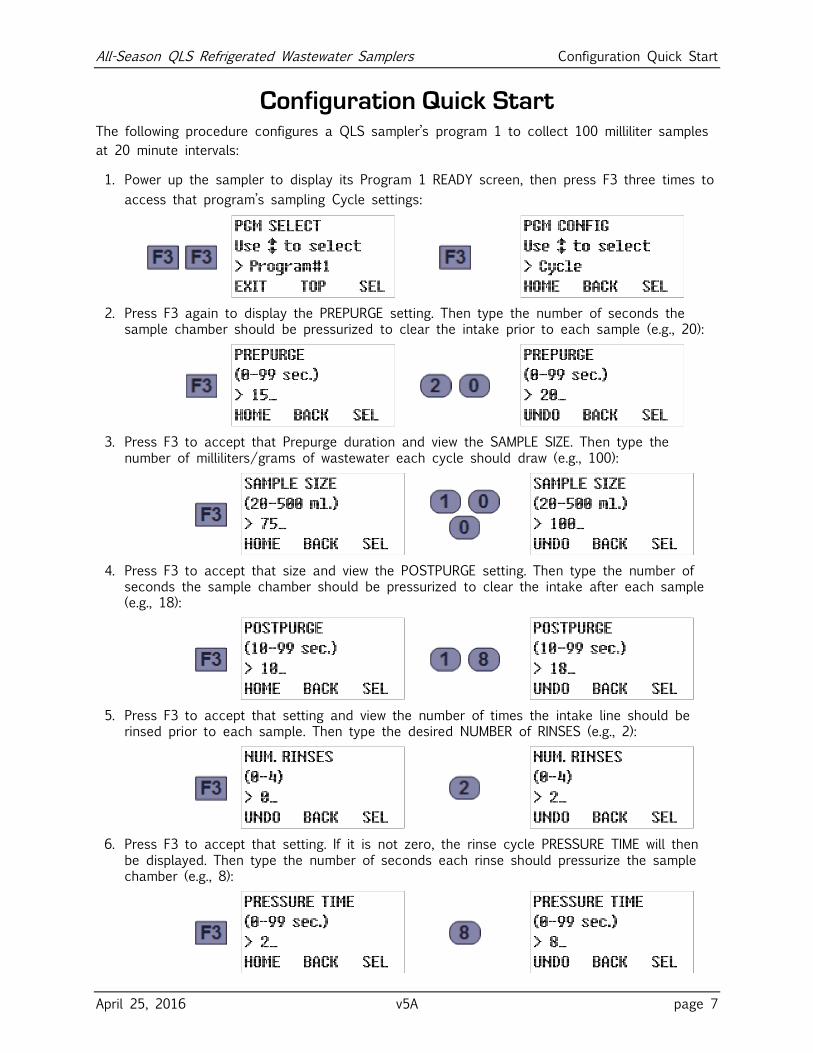
Configuration Quick Start The following procedure configures a QLS sampler’s program 1 to collect 100 milliliter samples
at 20 minute intervals:
1. Power up the sampler to display its Program 1 READY screen, then press F3 three times to
access that program’s sampling Cycle settings:
2. Press F3 again to display the PREPURGE setting. Then type the number of seconds the sample chamber should be pressurized to clear the intake prior to each sample (e.g., 20):
3. Press F3 to accept that Prepurge duration and view the SAMPLE SIZE. Then type the number of milliliters/grams of wastewater each cycle should draw (e.g., 100):
4. Press F3 to accept that size and view the POSTPURGE setting. Then type the number of seconds the sample chamber should be pressurized to clear the intake after each sample (e.g., 18):
5. Press F3 to accept that setting and view the number of times the intake line should be rinsed prior to each sample. Then type the desired NUMBER of RINSES (e.g., 2):
6. Press F3 to accept that setting. If it is not zero, the rinse cycle PRESSURE TIME will then be displayed. Then type the number of seconds each rinse should pressurize the sample chamber (e.g., 8):
All-Season QLS Refrigerated Wastewater Samplers Configuration Quick Start
April 25, 2016 v5A page 8
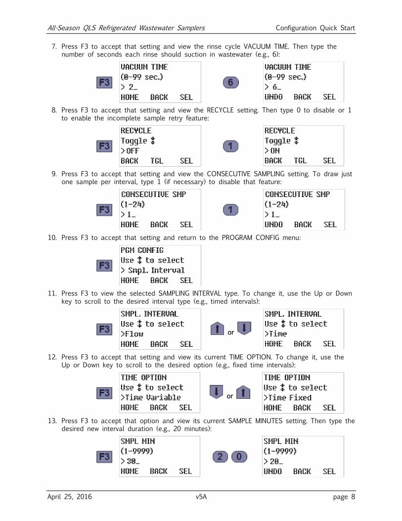
7. Press F3 to accept that setting and view the rinse cycle VACUUM TIME. Then type the number of seconds each rinse should suction in wastewater (e.g., 6):
8. Press F3 to accept that setting and view the RECYCLE setting. Then type 0 to disable or 1 to enable the incomplete sample retry feature:
9. Press F3 to accept that setting and view the CONSECUTIVE SAMPLING setting. To draw just one sample per interval, type 1 (if necessary) to disable that feature:
10. Press F3 to accept that setting and return to the PROGRAM CONFIG menu:
11. Press F3 to view the selected SAMPLING INTERVAL type. To change it, use the Up or Down key to scroll to the desired interval type (e.g., timed intervals):
or
12. Press F3 to accept that setting and view its current TIME OPTION. To change it, use the Up or Down key to scroll to the desired option (e.g., fixed time intervals):
or
13. Press F3 to accept that option and view its current SAMPLE MINUTES setting. Then type the desired new interval duration (e.g., 20 minutes):
All-Season QLS Refrigerated Wastewater Samplers Composite Sample Storage
April 25, 2016 v5A page 9
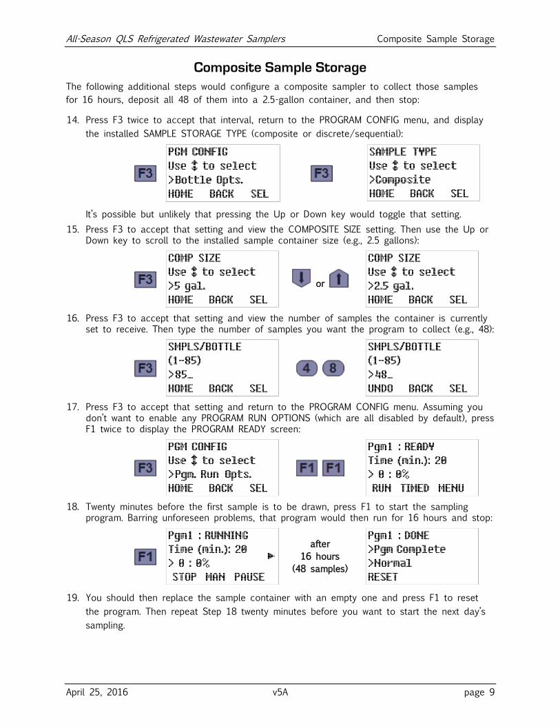
Composite Sample Storage
The following additional steps would configure a composite sampler to collect those samples
for 16 hours, deposit all 48 of them into a 2.5-gallon container, and then stop:
14. Press F3 twice to accept that interval, return to the PROGRAM CONFIG menu, and display
the installed SAMPLE STORAGE TYPE (composite or discrete/sequential):
It’s possible but unlikely that pressing the Up or Down key would toggle that setting.
15. Press F3 to accept that setting and view the COMPOSITE SIZE setting. Then use the Up or Down key to scroll to the installed sample container size (e.g., 2.5 gallons):
or
16. Press F3 to accept that setting and view the number of samples the container is currently set to receive. Then type the number of samples you want the program to collect (e.g., 48):
17. Press F3 to accept that setting and return to the PROGRAM CONFIG menu. Assuming you don’t want to enable any PROGRAM RUN OPTIONS (which are all disabled by default), press F1 twice to display the PROGRAM READY screen:
18. Twenty minutes before the first sample is to be drawn, press F1 to start the sampling program. Barring unforeseen problems, that program would then run for 16 hours and stop:
after
16 hours
(48 samples)
19. You should then replace the sample container with an empty one and press F1 to reset
the program. Then repeat Step 18 twenty minutes before you want to start the next day’s
sampling.
All-Season QLS Refrigerated Wastewater Samplers Sequential Sample Storage
April 25, 2016 v5A page 10
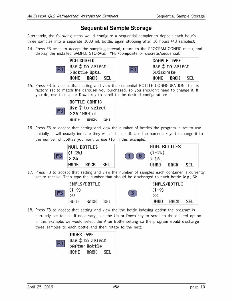
Sequential Sample Storage
Alternately, the following steps would configure a sequential sampler to deposit each hour’s
three samples into a separate 1000 mL bottle, again stopping after 16 hours (48 samples):
14. Press F3 twice to accept the sampling interval, return to the PROGRAM CONFIG menu, and display the installed SAMPLE STORAGE TYPE (composite or discrete/sequential):
15. Press F3 to accept that setting and view the sequential BOTTLE CONFIGURATION. This is factory set to match the carousel you purchased, so you shouldn’t need to change it. If you do, use the Up or Down key to scroll to the desired configuration:
16. Press F3 to accept that setting and view the number of bottles the program is set to use
(initially, it will usually indicate they will all be used). Use the numeric keys to change it to
the number of bottles you want to use (16 in this example):
17. Press F3 to accept that setting and view the number of samples each container is currently set to receive. Then type the number that should be discharged to each bottle (e.g., 3):
18. Press F3 to accept that setting and view the the bottle indexing option the program is
currently set to use. If necessary, use the Up or Down key to scroll to the desired option.
In this example, we would select the After Bottle setting so the program would discharge
three samples to each bottle and then rotate to the next:
All-Season QLS Refrigerated Wastewater Samplers Sequential Sample Storage
April 25, 2016 v5A page 11
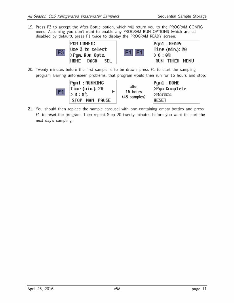
19. Press F3 to accept the After Bottle option, which will return you to the PROGRAM CONFIG menu. Assuming you don’t want to enable any PROGRAM RUN OPTIONS (which are all disabled by default), press F1 twice to display the PROGRAM READY screen:
20. Twenty minutes before the first sample is to be drawn, press F1 to start the sampling
program. Barring unforeseen problems, that program would then run for 16 hours and stop:
after
16 hours
(48 samples)
21. You should then replace the sample carousel with one containing empty bottles and press
F1 to reset the program. Then repeat Step 20 twenty minutes before you want to start the
next day’s sampling.
All-Season QLS Refrigerated Wastewater Samplers Operation Quick Start
April 25, 2016 v5A page 12
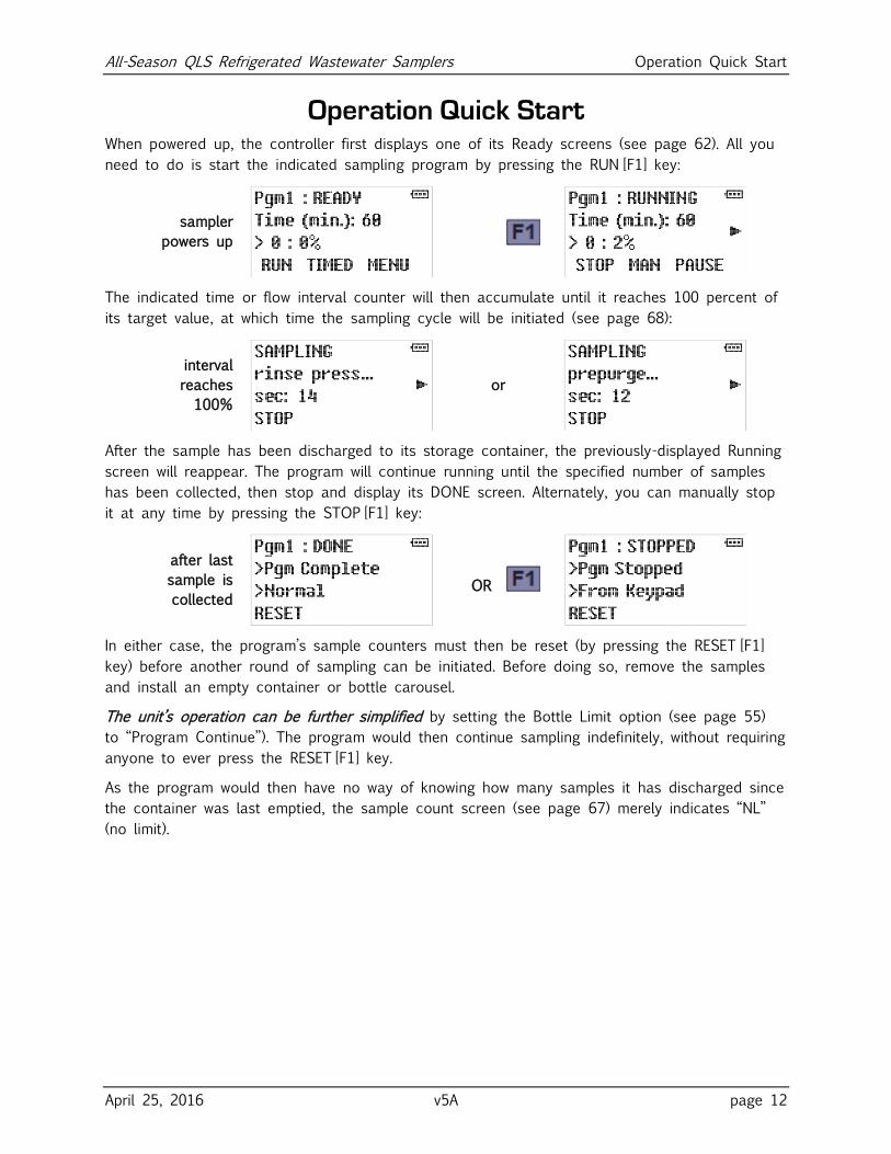
Operation Quick Start When powered up, the controller first displays one of its Ready screens (see page 62). All you
need to do is start the indicated sampling program by pressing the RUN [F1] key:
sampler
powers up
The indicated time or flow interval counter will then accumulate until it reaches 100 percent of
its target value, at which time the sampling cycle will be initiated (see page 68):
interval
reaches
100%
or
After the sample has been discharged to its storage container, the previously-displayed Running
screen will reappear. The program will continue running until the specified number of samples
has been collected, then stop and display its DONE screen. Alternately, you can manually stop
it at any time by pressing the STOP [F1] key:
after last
sample is
collected
OR
In either case, the program’s sample counters must then be reset (by pressing the RESET [F1]
key) before another round of sampling can be initiated. Before doing so, remove the samples
and install an empty container or bottle carousel.
The unit’s operation can be further simplified by setting the Bottle Limit option (see page 55)
to “Program Continue”). The program would then continue sampling indefinitely, without requiring
anyone to ever press the RESET [F1] key.
As the program would then have no way of knowing how many samples it has discharged since
the container was last emptied, the sample count screen (see page 67) merely indicates “NL”
(no limit).
All-Season QLS Refrigerated Wastewater Samplers Introduction
April 25, 2016 v5A page 13
Chapter 1: Introduction All-Season QLS Samplers collect specified volumes of wastewater at programmed time or flow
intervals and deposit them into refrigerated composite or sequential sample containers. Their
patented Quick Lift Sampler (QLS) systems precisely weigh each sample and self-calibrate to
maintain the specified sample size. Their piston vacuum pumps provide long-term consistent
sampling with vertical lifts of up to 28 feet, with no need to frequently replace the internal
tubes that render peristaltic pumps inconsistent, unreliable and costly to maintain.
All-Season Samplers are available in three different configurations, each of which uses either
the all-fiberglass Optima cabinet or the slightly larger Premium cabinet:
The slightly-larger Premium Sampler has a stainless-steel lower shell and can accommodate
any of our composite or sequential sample container systems.
Dual Samplers house two independent sampling systems in a single Premium cabinet, but
both cannot be equipped with large-container sequential carousels (two 24 x 500 milliliter
carousels will fit, or one 24 x 500 ml carousel paired with any composite container).
The slightly-smaller Optima cabinet has a fiberglass lower shell, which can accommodate all
but the largest of our sample container systems (the 4 x 2 ½ gallon carousel will not fit,
not will the 2 x 5 gallon carousel).
If you have any questions or suggestions, feel free to call QCEC at 1-515-266-2268 and ask
for wastewater sampling technical support.
1.1: Revision Notes
All-Season QLS Samplers manufactured since early February of 2015 boast several new
software features:
Each program can now be set to automatically start, pause, halt, resume, and stop, and/or
collect samples, at precise times on each day of the week.
Each can also be set to run continuously, with absolutely no operator intervention other
than changing the sample container(s) at appropriate times.
Most of these samplers are equipped with a redesigned sample chamber that fills from the top,
which should drain better than its bottom-fed predecessor because it has steeper sides and no
internal tubes.
Beginning in early 2016, all such samplers have also been factory-equipped for easy conversion
between their composite and sequential sampling configurations.
In addition, All-Season QLS Samplers manufactured since mid-March of 2016 record time-
stamped sampling data you can review from the user interface panel at virtually any time (see
Reviewing Archived Data on page 74).
All-Season QLS Refrigerated Wastewater Samplers Introduction
April 25, 2016 v5A page 14
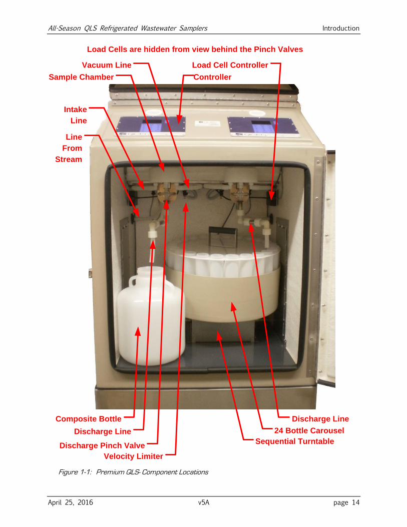
Discharge Line
Sample Chamber
Intake
Line
Velocity Limiter
Load Cell Controller
Discharge Pinch Valve
24 Bottle Carousel
Sequential Turntable
Vacuum Line
Controller
Composite Bottle
Load Cells are hidden from view behind the Pinch Valves
Line
From
Stream
Discharge Line
Figure 1-1: Premium QLS- Component Locations
All-Season QLS Refrigerated Wastewater Samplers Introduction
April 25, 2016 v5A page 15
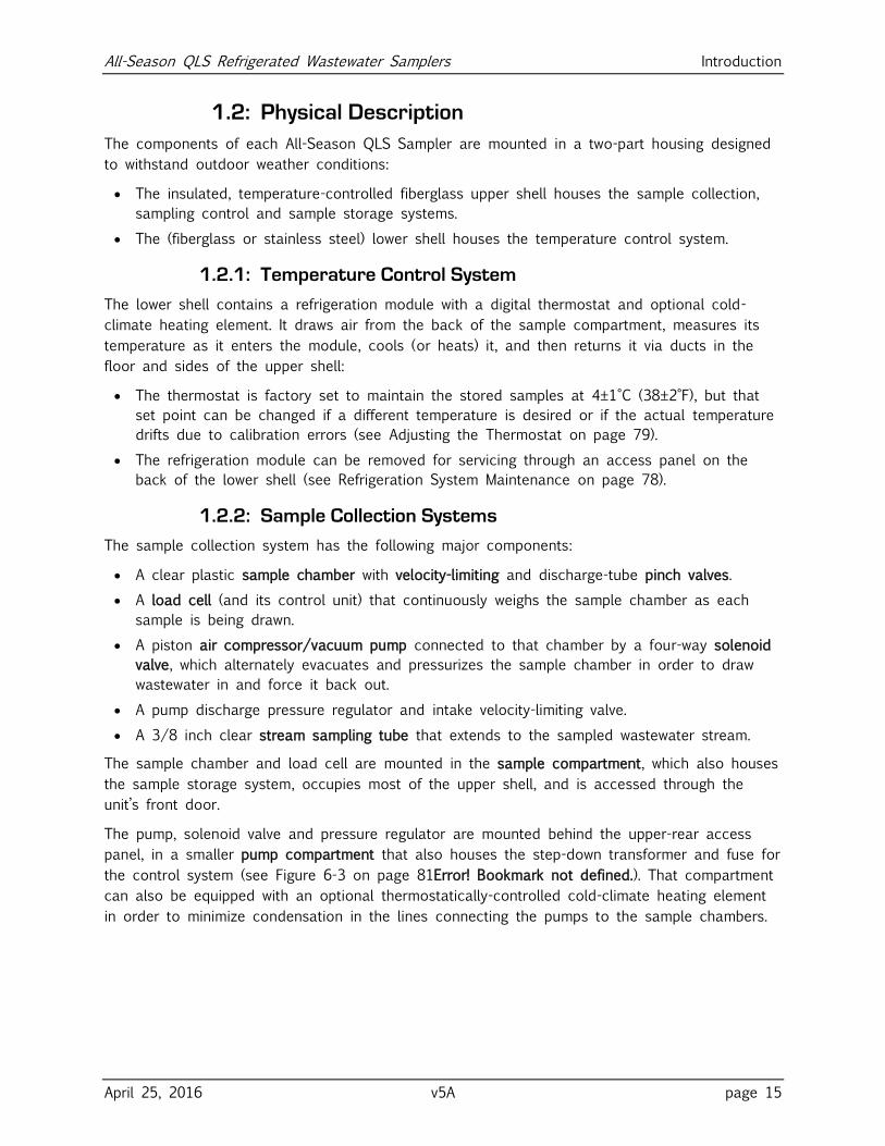
1.2: Physical Description
The components of each All-Season QLS Sampler are mounted in a two-part housing designed
to withstand outdoor weather conditions:
The insulated, temperature-controlled fiberglass upper shell houses the sample collection,
sampling control and sample storage systems.
The (fiberglass or stainless steel) lower shell houses the temperature control system.
1.2.1: Temperature Control System
The lower shell contains a refrigeration module with a digital thermostat and optional cold-
climate heating element. It draws air from the back of the sample compartment, measures its
temperature as it enters the module, cools (or heats) it, and then returns it via ducts in the
floor and sides of the upper shell:
The thermostat is factory set to maintain the stored samples at 4±1°C (38±2°F), but that
set point can be changed if a different temperature is desired or if the actual temperature
drifts due to calibration errors (see Adjusting the Thermostat on page 79).
The refrigeration module can be removed for servicing through an access panel on the
back of the lower shell (see Refrigeration System Maintenance on page 78).
1.2.2: Sample Collection Systems
The sample collection system has the following major components:
A clear plastic sample chamber with velocity-limiting and discharge-tube pinch valves.
A load cell (and its control unit) that continuously weighs the sample chamber as each
sample is being drawn.
A piston air compressor/vacuum pump connected to that chamber by a four-way solenoid
valve, which alternately evacuates and pressurizes the sample chamber in order to draw
wastewater in and force it back out.
A pump discharge pressure regulator and intake velocity-limiting valve.
A 3/8 inch clear stream sampling tube that extends to the sampled wastewater stream.
The sample chamber and load cell are mounted in the sample compartment, which also houses
the sample storage system, occupies most of the upper shell, and is accessed through the
unit’s front door.
The pump, solenoid valve and pressure regulator are mounted behind the upper-rear access
panel, in a smaller pump compartment that also houses the step-down transformer and fuse for
the control system (see Figure 6-3 on page 81Error! Bookmark not defined.). That compartment
can also be equipped with an optional thermostatically-controlled cold-climate heating element
in order to minimize condensation in the lines connecting the pumps to the sample chambers.
All-Season QLS Refrigerated Wastewater Samplers Introduction
April 25, 2016 v5A page 16
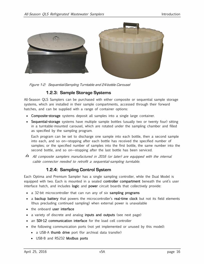
Figure 1-2: Sequential-Sampling Turntable and 24-bottle Carousel
1.2.3: Sample Storage Systems
All-Season QLS Samplers can be purchased with either composite or sequential sample storage
systems, which are installed in their sample compartments, accessed through their forward
hatches, and can be supplied with a range of container options:
Composite-storage systems deposit all samples into a single large container.
Sequential-storage systems have multiple sample bottles (usually two or twenty four) sitting
in a turntable-mounted carousel, which are rotated under the sampling chamber and filled
as specified by the sampling program.
Each program can be set to discharge one sample into each bottle, then a second sample
into each, and so on—stopping after each bottle has received the specified number of
samples; or the specified number of samples into the first bottle, the same number into the
second bottle, and so on—stopping after the last bottle has been serviced.
✍ All composite samplers manufactured in 2016 (or later) are equipped with the internal
cable connector needed to retrofit a sequential-sampling turntable.
1.2.4: Sampling Control System
Each Optima and Premium Sampler has a single sampling controller, while the Dual Model is
equipped with two. Each is mounted in a sealed controller compartment beneath the unit’s user
interface hatch, and includes logic and power circuit boards that collectively provide:
a 32-bit microcontroller that can run any of six sampling programs
a backup battery that powers the microcontroller’s real-time clock but not its field elements
(thus precluding continued sampling) when external power is unavailable
the onboard user interface
a variety of discrete and analog inputs and outputs (see next page)
an SDI-12 communication interface for the load cell controller
the following communication ports (not yet implemented or unused by this model):
a USB-A thumb drive port (for archival data transfer)
USB-B and RS232 Modbus ports
All-Season QLS Refrigerated Wastewater Samplers Introduction
April 25, 2016 v5A page 17
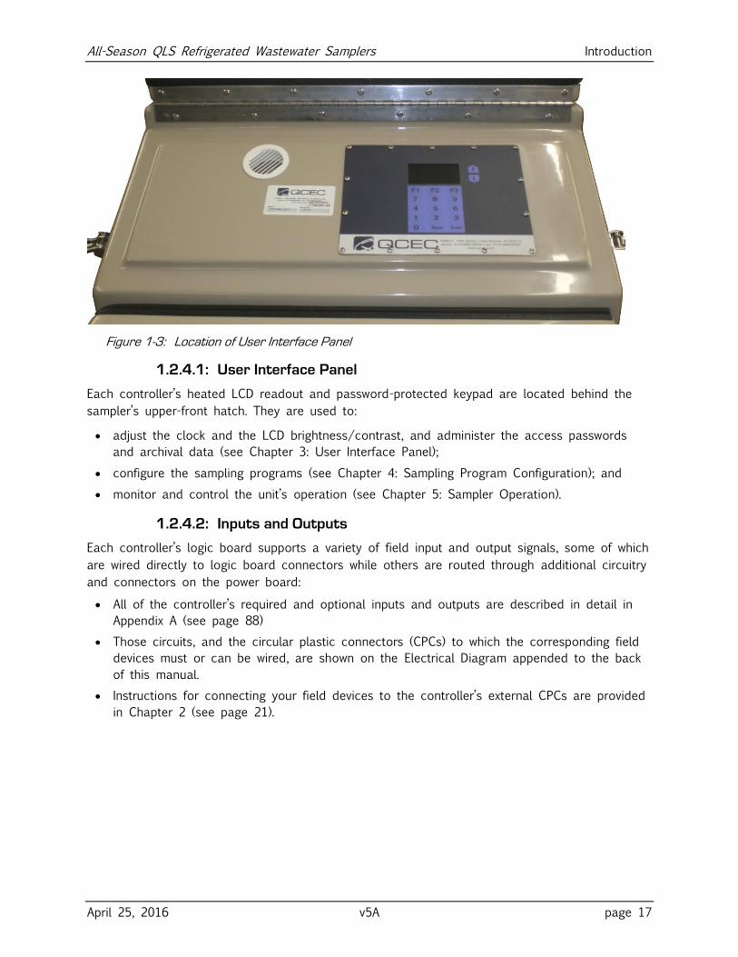
Figure 1-3: Location of User Interface Panel
1.2.4.1: User Interface Panel
Each controller’s heated LCD readout and password-protected keypad are located behind the
sampler’s upper-front hatch. They are used to:
adjust the clock and the LCD brightness/contrast, and administer the access passwords
and archival data (see Chapter 3: User Interface Panel);
configure the sampling programs (see Chapter 4: Sampling Program Configuration); and
monitor and control the unit’s operation (see Chapter 5: Sampler Operation).
1.2.4.2: Inputs and Outputs
Each controller’s logic board supports a variety of field input and output signals, some of which
are wired directly to logic board connectors while others are routed through additional circuitry
and connectors on the power board:
All of the controller’s required and optional inputs and outputs are described in detail in
Appendix A (see page 88)
Those circuits, and the circular plastic connectors (CPCs) to which the corresponding field
devices must or can be wired, are shown on the Electrical Diagram appended to the back
of this manual.
Instructions for connecting your field devices to the controller’s external CPCs are provided
in Chapter 2 (see page 21).
All-Season QLS Refrigerated Wastewater Samplers Introduction
April 25, 2016 v5A page 18
1.3: Sampling Programs
Each control system provides six user-configurable sampling programs, one of which is selected
and can be run at any given time. Each of those programs can be configured to:
draw configurable, fixed-size (20 to 500 milliliter) samples, or sets of consecutive samples,
at specified time or flow intervals.
Flow intervals can be based on either an analog or a discrete-pulse flow meter signal, or a
PLC or other remote device could use the pulsing flow input to trigger individual samples.
rinse the sampling line up to four times prior to drawing each sample.
repeat any sampling cycle up to four times (five total) if needed to collect the specified
volume of wastewater.
discharge each sample into a specified sequential-sampling bottle (if so equipped).
delay its execution a specified number of minutes after it is started, or until the optional
float input is asserted.
automatically stop after a configurable amount of time or number of samples, or if the
sample volumes discharged to any bottle exceed 90 percent of its capacity.
AND/OR
suspend and resume sampling as an optional external float switch opens and closes.
Alternately, a PLC or other remote device could use the external float-switch input to
remotely suspend and resume the collection of samples.
start sampling, pause or halt and later resume, take manual samples and finally stop at
scheduled times on specified days of the week, then automatically restart itself if desired.
energize a run-status relay to indicate a sample is being collected, or an alarm relay to
indicate the program has stopped or encountered a fault condition.
Appendix A: Controller Capabilities discusses the configurable features of the sampling program,
while Chapter 4: Sampling Program Configuration tells how to view and change the parameters
that configure those features.
All-Season QLS Refrigerated Wastewater Samplers Installation
April 25, 2016 v5A page 19
Chapter 2: Installation All-Season Samplers are meant to be used in fixed locations, with any optional external I/O
devices connected, the far ends of their sampling lines fixed in the waste streams they are to
sample, and their power cords plugged into alternating-current power receptacles.
When you are ready to install your sampler:
1. Move it to its intended final location, remove its protective packaging, lift it from its
shipping pallet and set it in its intended position.
2. Adjust the feet so the sampler is approximately level.
3. Install the wastewater intake line(s) and strainer(s).
4. Connect any external I/O devices (flow and/or float inputs, run and/or alarm outputs).
5. Plug the provided power cord into a grounded AC power receptacle.
6. Verify or correct the control system clock settings (see page 28).
7. Configure the sampling program(s) to your needs (see page 32).
8. When lifting small samples, you may need to adjust the velocity valve (see next page).
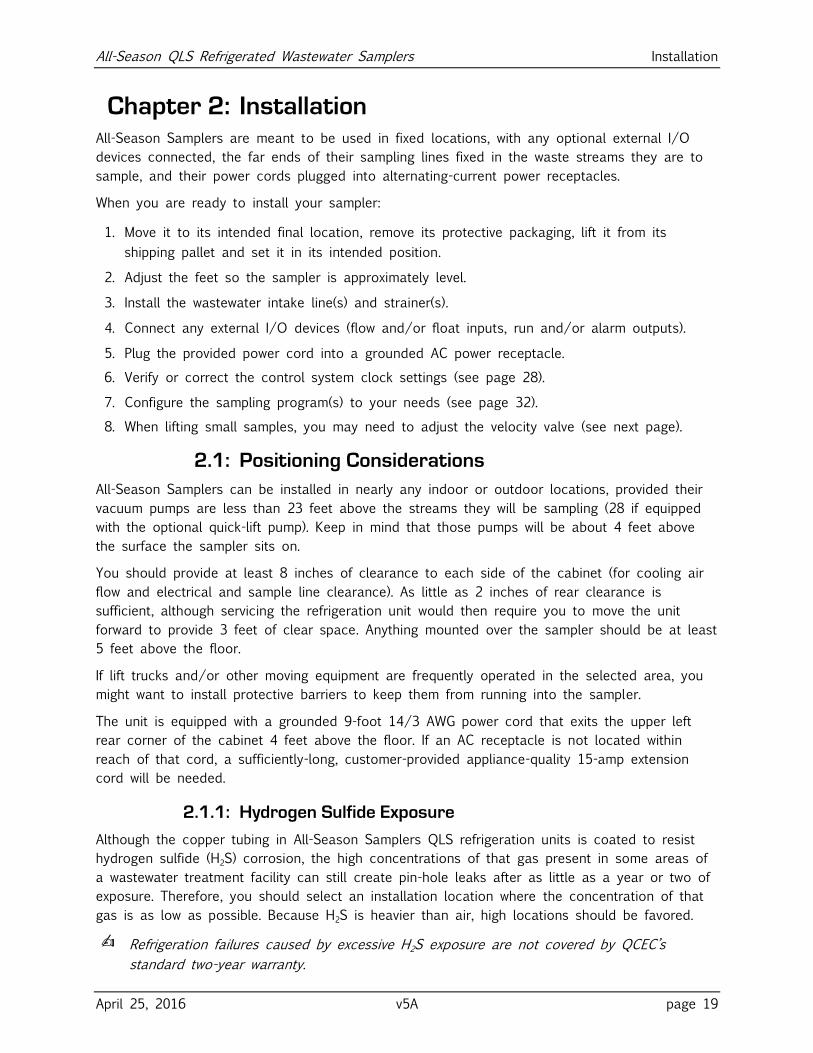
2.1: Positioning Considerations
All-Season Samplers can be installed in nearly any indoor or outdoor locations, provided their
vacuum pumps are less than 23 feet above the streams they will be sampling (28 if equipped
with the optional quick-lift pump). Keep in mind that those pumps will be about 4 feet above
the surface the sampler sits on.
You should provide at least 8 inches of clearance to each side of the cabinet (for cooling air
flow and electrical and sample line clearance). As little as 2 inches of rear clearance is
sufficient, although servicing the refrigeration unit would then require you to move the unit
forward to provide 3 feet of clear space. Anything mounted over the sampler should be at least
5 feet above the floor.
If lift trucks and/or other moving equipment are frequently operated in the selected area, you
might want to install protective barriers to keep them from running into the sampler.
The unit is equipped with a grounded 9-foot 14/3 AWG power cord that exits the upper left
rear corner of the cabinet 4 feet above the floor. If an AC receptacle is not located within
reach of that cord, a sufficiently-long, customer-provided appliance-quality 15-amp extension
cord will be needed.
2.1.1: Hydrogen Sulfide Exposure
Although the copper tubing in All-Season Samplers QLS refrigeration units is coated to resist
hydrogen sulfide (H2S) corrosion, the high concentrations of that gas present in some areas of
a wastewater treatment facility can still create pin-hole leaks after as little as a year or two of
exposure. Therefore, you should select an installation location where the concentration of that
gas is as low as possible. Because H2S is heavier than air, high locations should be favored.
✍ Refrigeration failures caused by excessive H2S exposure are not covered by QCEC’s
standard two-year warranty.
All-Season QLS Refrigerated Wastewater Samplers Installation
April 25, 2016 v5A page 20
2.2: Sampling Line Connection
The wastewater inlet connection is a 1/2 inch FNPT fitting recessed into the left side of the
upper shell (Dual Models have one on each side). You can connect any appropriate plumbing
materials, but the most common choice is 3/8 by 5/8 inch (I.D. by O.D.) clear PVC tubing
connected using a right-angle barbed or compression fitting. Either fitting and needed length of
tubing can be purchased from QCEC.
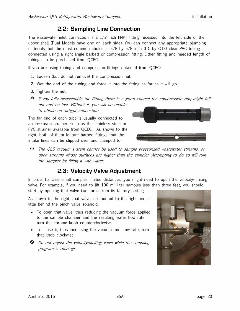
If you are using tubing and compression fittings obtained from QCEC:
1. Loosen (but do not remove) the compression nut.
2. Wet the end of the tubing and force it into the fitting as far as it will go.
3. Tighten the nut.
✍ If you fully disassemble the fitting, there is a good chance the compression ring might fall
out and be lost. Without it, you will be unable
to obtain an airtight connection.
The far end of each tube is usually connected to
an in-stream strainer, such as the stainless steel or
PVC strainer available from QCEC. As shown to the
right, both of them feature barbed fittings that the
intake lines can be slipped over and clamped to.
⦸ The QLS vacuum system cannot be used to sample pressurized wastewater streams, or
open streams whose surfaces are higher than the sampler. Attempting to do so will ruin
the sampler by filling it with water.
2.3: Velocity Valve Adjustment
In order to raise small samples limited distances, you might need to open the velocity-limiting
valve. For example, if you need to lift 100 milliliter samples less than three feet, you should
start by opening that valve two turns from its factory setting.
As shown to the right, that valve is mounted to the right and a
little behind the pinch valve solenoid:
To open that valve, thus reducing the vacuum force applied
to the sample chamber and the resulting water flow rate,
turn the chrome knob counterclockwise.
To close it, thus increasing the vacuum and flow rate, turn
that knob clockwise.
⦸ Do not adjust the velocity-limiting valve while the sampling
program is running!
All-Season QLS Refrigerated Wastewater Samplers Installation
April 25, 2016 v5A page 21
2.4: Field I/O Connections
Circular plastic connectors (CPCs) are mounted in the upper right side of Optima and Premium
(and both sides of Dual) cabinets for the field I/O devices:
a four-pin flow inputs connector (analog and/or pulsing-discrete signals)
an optional seven-pin field I/O connector (alarm and run output and float input signals)
Custom cables must be fabricated (from the provided matching screw-terminal cable connectors)
for any you chose to use.
2
1
4
3
Analog Flow Signal(4-20mA | 0-10VDC | 0-5VDC)
Pulsing Signal(Dry Contacts)
FT
External Connector
Analog Input
Pulse Input
~ +
˗
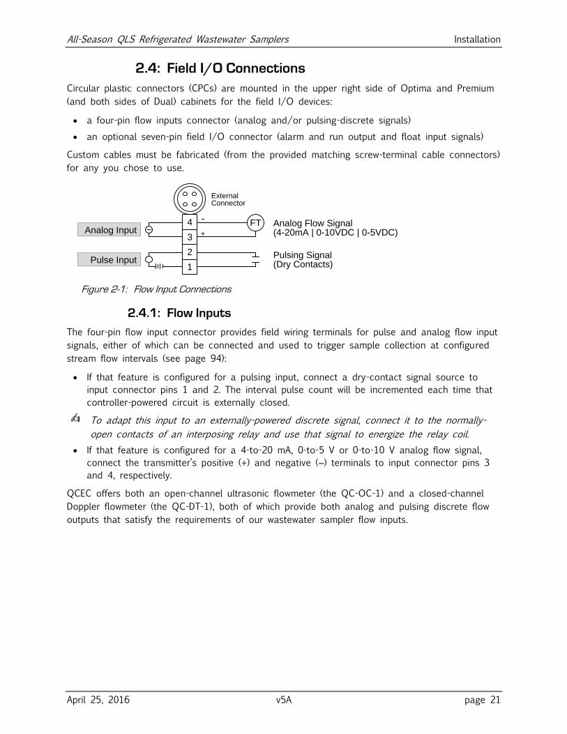
Figure 2-1: Flow Input Connections
2.4.1: Flow Inputs
The four-pin flow input connector provides field wiring terminals for pulse and analog flow input
signals, either of which can be connected and used to trigger sample collection at configured
stream flow intervals (see page 94):
If that feature is configured for a pulsing input, connect a dry-contact signal source to
input connector pins 1 and 2. The interval pulse count will be incremented each time that
controller-powered circuit is externally closed.
✍ To adapt this input to an externally-powered discrete signal, connect it to the normally-
open contacts of an interposing relay and use that signal to energize the relay coil.
If that feature is configured for a 4-to-20 mA, 0-to-5 V or 0-to-10 V analog flow signal,
connect the transmitter’s positive (+) and negative (‒) terminals to input connector pins 3
and 4, respectively.
QCEC offers both an open-channel ultrasonic flowmeter (the QC-OC-1) and a closed-channel
Doppler flowmeter (the QC-DT-1), both of which provide both analog and pulsing discrete flow
outputs that satisfy the requirements of our wastewater sampler flow inputs.
All-Season QLS Refrigerated Wastewater Samplers Installation
April 25, 2016 v5A page 22
Run Relay
Alarm Relay
Float Input
5A max.
5A max.
3 41 2 6 75External
Connector
Stream-Level Float Switch
Run Monitor
Alarm Monitor
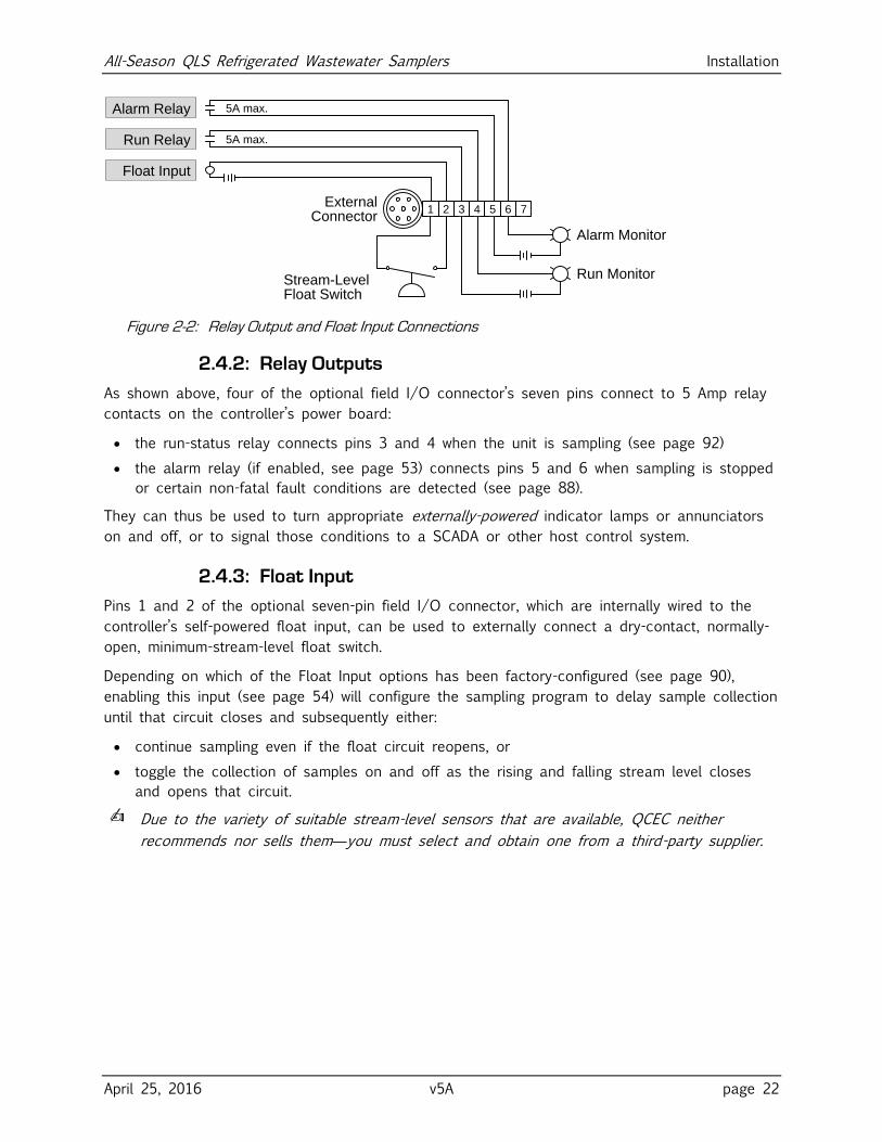
Figure 2-2: Relay Output and Float Input Connections
2.4.2: Relay Outputs
As shown above, four of the optional field I/O connector’s seven pins connect to 5 Amp relay
contacts on the controller’s power board:
the run-status relay connects pins 3 and 4 when the unit is sampling (see page 92)
the alarm relay (if enabled, see page 53) connects pins 5 and 6 when sampling is stopped
or certain non-fatal fault conditions are detected (see page 88).
They can thus be used to turn appropriate externally-powered indicator lamps or annunciators
on and off, or to signal those conditions to a SCADA or other host control system.
2.4.3: Float Input
Pins 1 and 2 of the optional seven-pin field I/O connector, which are internally wired to the
controller’s self-powered float input, can be used to externally connect a dry-contact, normally-
open, minimum-stream-level float switch.
Depending on which of the Float Input options has been factory-configured (see page 90),
enabling this input (see page 54) will configure the sampling program to delay sample collection
until that circuit closes and subsequently either:
continue sampling even if the float circuit reopens, or
toggle the collection of samples on and off as the rising and falling stream level closes
and opens that circuit.
✍ Due to the variety of suitable stream-level sensors that are available, QCEC neither
recommends nor sells them—you must select and obtain one from a third-party supplier.
All-Season QLS Refrigerated Wastewater Samplers User Interface Panel
April 25, 2016 v5A page 23
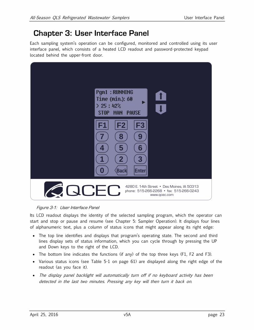
Chapter 3: User Interface Panel Each sampling system’s operation can be configured, monitored and controlled using its user
interface panel, which consists of a heated LCD readout and password-protected keypad
located behind the upper-front door.
QCEC4280 E. 14th Street • Des Moines, IA 50313
phone: 515-266-2268 • fax: 515-266-0243www.qcec.com
F1
21 3
54 6
87 9
0
F2 F3
Back Enter
Figure 3-1: User Interface Panel
Its LCD readout displays the identity of the selected sampling program, which the operator can
start and stop or pause and resume (see Chapter 5: Sampler Operation). It displays four lines
of alphanumeric text, plus a column of status icons that might appear along its right edge:
The top line identifies and displays that program’s operating state. The second and third
lines display sets of status information, which you can cycle through by pressing the UP
and Down keys to the right of the LCD.
The bottom line indicates the functions (if any) of the top three keys (F1, F2 and F3).
Various status icons (see Table 5-1 on page 61) are displayed along the right edge of the
readout (as you face it).
The display panel backlight will automatically turn off if no keyboard activity has been
detected in the last two minutes. Pressing any key will then turn it back on.
All-Season QLS Refrigerated Wastewater Samplers User Interface Panel
April 25, 2016 v5A page 24
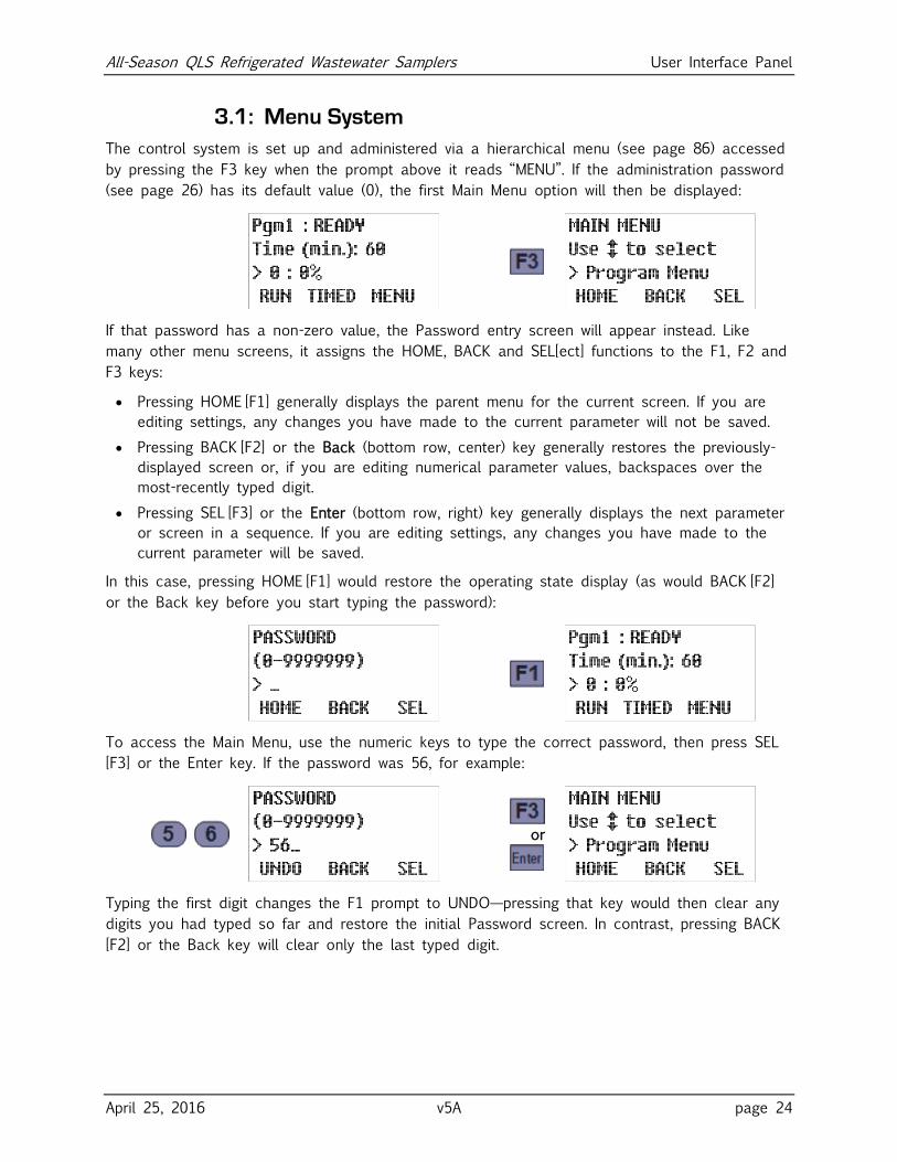
3.1: Menu System
The control system is set up and administered via a hierarchical menu (see page 86) accessed
by pressing the F3 key when the prompt above it reads “MENU”. If the administration password
(see page 26) has its default value (0), the first Main Menu option will then be displayed:
If that password has a non-zero value, the Password entry screen will appear instead. Like
many other menu screens, it assigns the HOME, BACK and SEL[ect] functions to the F1, F2 and
F3 keys:
Pressing HOME [F1] generally displays the parent menu for the current screen. If you are
editing settings, any changes you have made to the current parameter will not be saved.
Pressing BACK [F2] or the Back (bottom row, center) key generally restores the previously-
displayed screen or, if you are editing numerical parameter values, backspaces over the
most-recently typed digit.
Pressing SEL [F3] or the Enter (bottom row, right) key generally displays the next parameter
or screen in a sequence. If you are editing settings, any changes you have made to the
current parameter will be saved.
In this case, pressing HOME [F1] would restore the operating state display (as would BACK [F2]
or the Back key before you start typing the password):
To access the Main Menu, use the numeric keys to type the correct password, then press SEL
[F3] or the Enter key. If the password was 56, for example:
or
Typing the first digit changes the F1 prompt to UNDO—pressing that key would then clear any
digits you had typed so far and restore the initial Password screen. In contrast, pressing BACK
[F2] or the Back key will clear only the last typed digit.
All-Season QLS Refrigerated Wastewater Samplers User Interface Panel
April 25, 2016 v5A page 25
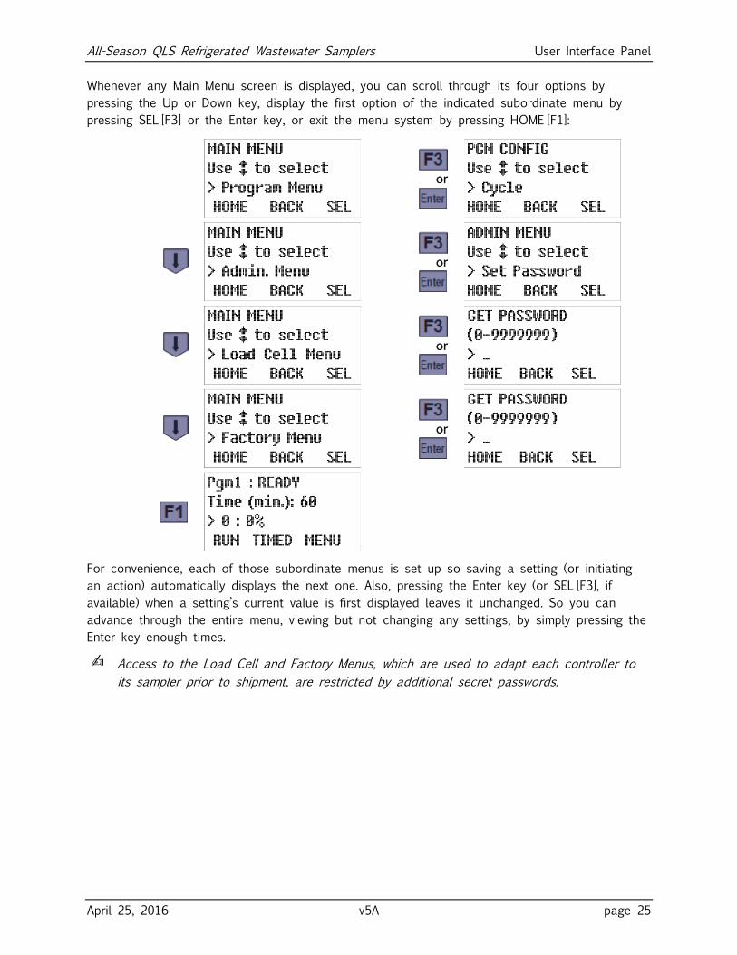
Whenever any Main Menu screen is displayed, you can scroll through its four options by
pressing the Up or Down key, display the first option of the indicated subordinate menu by
pressing SEL [F3] or the Enter key, or exit the menu system by pressing HOME [F1]:
or
or
or
or
For convenience, each of those subordinate menus is set up so saving a setting (or initiating
an action) automatically displays the next one. Also, pressing the Enter key (or SEL [F3], if
available) when a setting’s current value is first displayed leaves it unchanged. So you can
advance through the entire menu, viewing but not changing any settings, by simply pressing the
Enter key enough times.
✍ Access to the Load Cell and Factory Menus, which are used to adapt each controller to
its sampler prior to shipment, are restricted by additional secret passwords.
All-Season QLS Refrigerated Wastewater Samplers User Interface Panel
April 25, 2016 v5A page 26
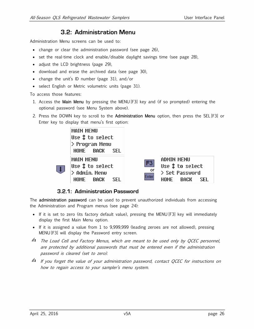
3.2: Administration Menu
Administration Menu screens can be used to:
change or clear the administration password (see page 26),
set the real-time clock and enable/disable daylight savings time (see page 28),
adjust the LCD brightness (page 29),
download and erase the archived data (see page 30),
change the unit’s ID number (page 31), and/or
select English or Metric volumetric units (page 31).
To access those features:
1. Access the Main Menu by pressing the MENU [F3] key and (if so prompted) entering the
optional password (see Menu System above).
2. Press the DOWN key to scroll to the Administration Menu option, then press the SEL [F3] or
Enter key to display that menu’s first option:
or
3.2.1: Administration Password
The administration password can be used to prevent unauthorized individuals from accessing
the Administration and Program menus (see page 24):
If it is set to zero (its factory default value), pressing the MENU [F3] key will immediately
display the first Main Menu option.
If it is assigned a value from 1 to 9,999,999 (leading zeroes are not allowed), pressing
MENU [F3] will display the Password entry screen.
✍ The Load Cell and Factory Menus, which are meant to be used only by QCEC personnel,
are protected by additional passwords that must be entered even if the administration
password is cleared (set to zero).
✍ If you forget the value of your administration password, contact QCEC for instructions on
how to regain access to your sampler’s menu system.
All-Season QLS Refrigerated Wastewater Samplers User Interface Panel
April 25, 2016 v5A page 27
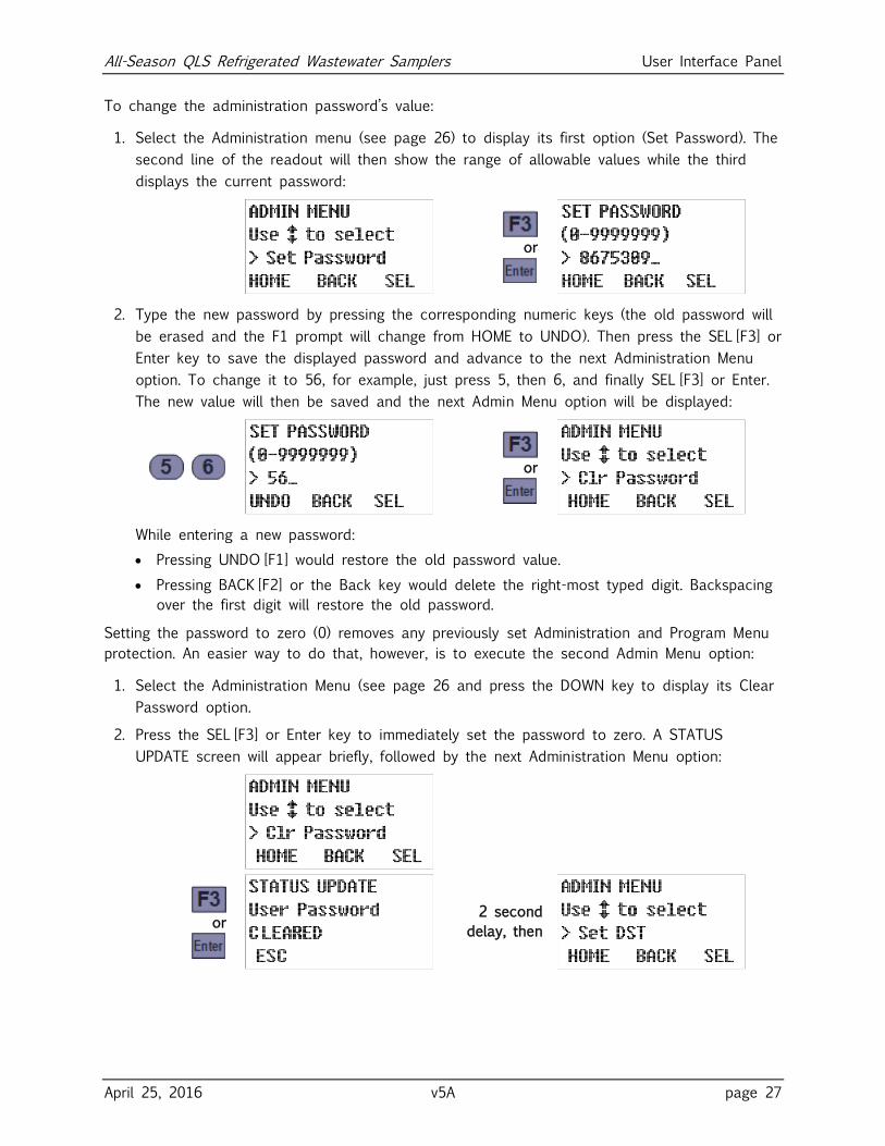
To change the administration password’s value:
1. Select the Administration menu (see page 26) to display its first option (Set Password). The
second line of the readout will then show the range of allowable values while the third
displays the current password:
or
2. Type the new password by pressing the corresponding numeric keys (the old password will
be erased and the F1 prompt will change from HOME to UNDO). Then press the SEL [F3] or
Enter key to save the displayed password and advance to the next Administration Menu
option. To change it to 56, for example, just press 5, then 6, and finally SEL [F3] or Enter.
The new value will then be saved and the next Admin Menu option will be displayed:
or
While entering a new password:
Pressing UNDO [F1] would restore the old password value.
Pressing BACK [F2] or the Back key would delete the right-most typed digit. Backspacing
over the first digit will restore the old password.
Setting the password to zero (0) removes any previously set Administration and Program Menu
protection. An easier way to do that, however, is to execute the second Admin Menu option:
1. Select the Administration Menu (see page 26 and press the DOWN key to display its Clear
Password option.
2. Press the SEL [F3] or Enter key to immediately set the password to zero. A STATUS
UPDATE screen will appear briefly, followed by the next Administration Menu option:
or
2 second
delay, then
All-Season QLS Refrigerated Wastewater Samplers User Interface Panel
April 25, 2016 v5A page 28
3.2.2: Clock Settings
The control board includes a real-time clock chip with a backup battery, so it runs even when
the control board is powered down. This enables it to timestamp all archived data and to
collect samples at scheduled times. In addition, the current time and date are displayed on the
third line of the second operating status screen (see page 66).
The third Administration Menu option allows you to quickly adjust the clock by one hour when
daylight savings time (DST) begins or ends, while the fourth allows you to directly reset the
clock to the current date and time. Because you should make sure the DST option is correct
before setting the time, those options should be executed in the order presented:
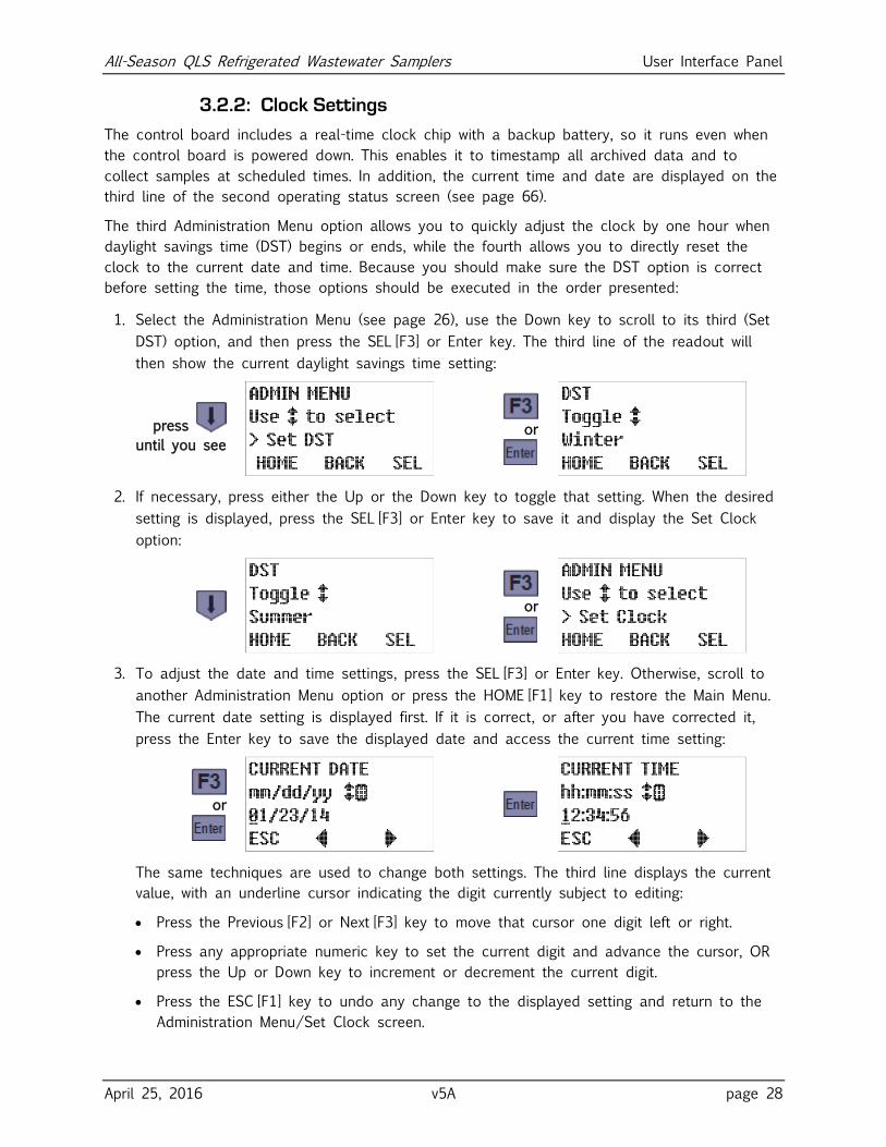
1. Select the Administration Menu (see page 26), use the Down key to scroll to its third (Set
DST) option, and then press the SEL [F3] or Enter key. The third line of the readout will
then show the current daylight savings time setting:
press
until you see
or
2. If necessary, press either the Up or the Down key to toggle that setting. When the desired
setting is displayed, press the SEL [F3] or Enter key to save it and display the Set Clock
option:
or
3. To adjust the date and time settings, press the SEL [F3] or Enter key. Otherwise, scroll to
another Administration Menu option or press the HOME [F1] key to restore the Main Menu.
The current date setting is displayed first. If it is correct, or after you have corrected it,
press the Enter key to save the displayed date and access the current time setting:
or
The same techniques are used to change both settings. The third line displays the current
value, with an underline cursor indicating the digit currently subject to editing:
Press the Previous [F2] or Next [F3] key to move that cursor one digit left or right.
Press any appropriate numeric key to set the current digit and advance the cursor, OR
press the Up or Down key to increment or decrement the current digit.
Press the ESC [F1] key to undo any change to the displayed setting and return to the
Administration Menu/Set Clock screen.
All-Season QLS Refrigerated Wastewater Samplers User Interface Panel
April 25, 2016 v5A page 29
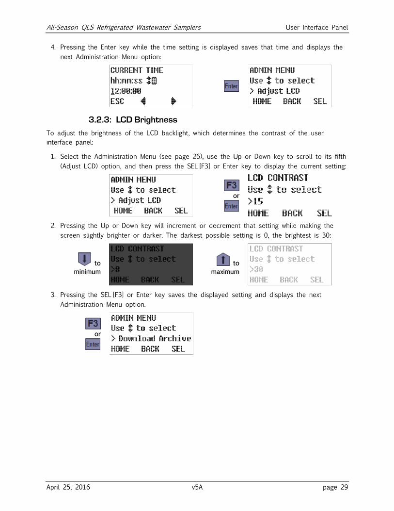
4. Pressing the Enter key while the time setting is displayed saves that time and displays the
next Administration Menu option:
3.2.3: LCD Brightness
To adjust the brightness of the LCD backlight, which determines the contrast of the user
interface panel:
1. Select the Administration Menu (see page 26), use the Up or Down key to scroll to its fifth
(Adjust LCD) option, and then press the SEL [F3] or Enter key to display the current setting:
or
2. Pressing the Up or Down key will increment or decrement that setting while making the
screen slightly brighter or darker. The darkest possible setting is 0, the brightest is 30:
to
minimum
to
maximum
3. Pressing the SEL [F3] or Enter key saves the displayed setting and displays the next
Administration Menu option.
or
All-Season QLS Refrigerated Wastewater Samplers User Interface Panel
April 25, 2016 v5A page 30
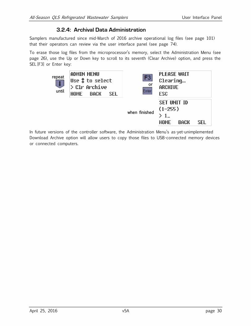
3.2.4: Archival Data Administration
Samplers manufactured since mid-March of 2016 archive operational log files (see page 101)
that their operators can review via the user interface panel (see page 74).
To erase those log files from the microprocessor’s memory, select the Administration Menu (see
page 26), use the Up or Down key to scroll to its seventh (Clear Archive) option, and press the
SEL [F3] or Enter key:
repeat
until
or
when finished
In future versions of the controller software, the Administration Menu’s as-yet-unimplemented
Download Archive option will allow users to copy those files to USB-connected memory devices
or connected computers.
All-Season QLS Refrigerated Wastewater Samplers User Interface Panel
April 25, 2016 v5A page 31
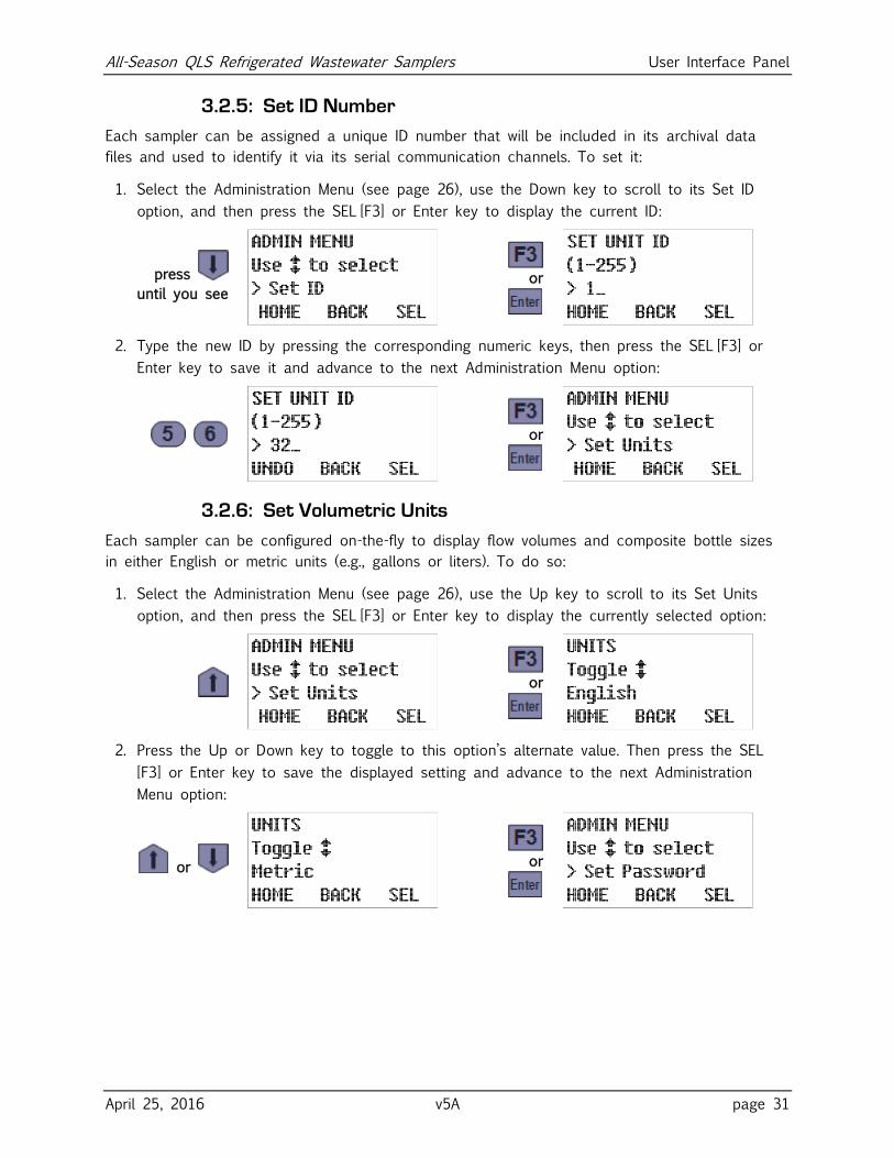
3.2.5: Set ID Number
Each sampler can be assigned a unique ID number that will be included in its archival data
files and used to identify it via its serial communication channels. To set it:
1. Select the Administration Menu (see page 26), use the Down key to scroll to its Set ID
option, and then press the SEL [F3] or Enter key to display the current ID:
press
until you see
or
2. Type the new ID by pressing the corresponding numeric keys, then press the SEL [F3] or
Enter key to save it and advance to the next Administration Menu option:
or
3.2.6: Set Volumetric Units
Each sampler can be configured on-the-fly to display flow volumes and composite bottle sizes
in either English or metric units (e.g., gallons or liters). To do so:
1. Select the Administration Menu (see page 26), use the Up key to scroll to its Set Units
option, and then press the SEL [F3] or Enter key to display the currently selected option:
or
2. Press the Up or Down key to toggle to this option’s alternate value. Then press the SEL
[F3] or Enter key to save the displayed setting and advance to the next Administration
Menu option:
or
or
All-Season QLS Refrigerated Wastewater Samplers Sampling Program Configuration
April 25, 2016 v5A page 32
Chapter 4: Sampling Program Configuration Each user interface panel’s Program Menu is used to configure that controller’s Sampling
Programs (see Appendix A:) and specify which is selected to be configured and/or started.
Although you can directly view and change individual parameters for each program, the menu
is designed so that all parameters for each program can be set in one continuous process:
Each program’s parameters are divided into several configuration groups.
Selecting a specific program displays the first parameter in its first group.
Pressing the SEL [F3] or Enter key (whether or not you have changed the displayed value)
displays the next parameter in the same group.
Options that are rendered inapplicable by those you have already set are not displayed.
Setting the last parameter in any group returns you to the Program Configuration menu
with the next parameter group selected.
In other words, simply access the Program Menu, select the program you want to configure,
and then keep pressing the SEL [F3] or Enter key as you verify or change each setting.
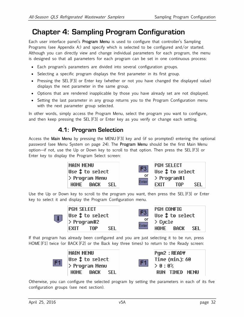
4.1: Program Selection
Access the Main Menu by pressing the MENU [F3] key and (if so prompted) entering the optional
password (see Menu System on page 24). The Program Menu should be the first Main Menu
option—if not, use the Up or Down key to scroll to that option. Then press the SEL [F3] or
Enter key to display the Program Select screen:
or
Use the Up or Down key to scroll to the program you want, then press the SEL [F3] or Enter
key to select it and display the Program Configuration menu.
or
If that program has already been configured and you are just selecting it to be run, press
HOME [F1] twice (or BACK [F2] or the Back key three times) to return to the Ready screen:
Otherwise, you can configure the selected program by setting the parameters in each of its five
configuration groups (see next section).
All-Season QLS Refrigerated Wastewater Samplers Sampling Program Configuration
April 25, 2016 v5A page 33
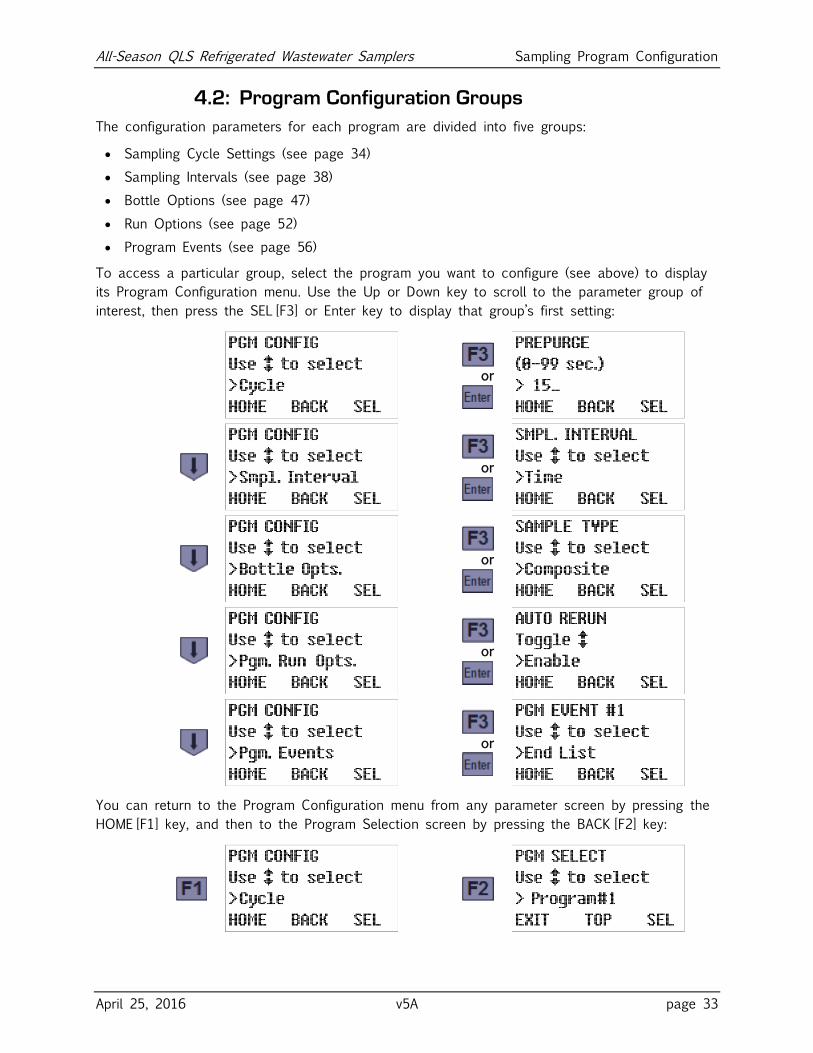
4.2: Program Configuration Groups
The configuration parameters for each program are divided into five groups:
Sampling Cycle Settings (see page 34)
Sampling Intervals (see page 38)
Bottle Options (see page 47)
Run Options (see page 52)
Program Events (see page 56)
To access a particular group, select the program you want to configure (see above) to display
its Program Configuration menu. Use the Up or Down key to scroll to the parameter group of
interest, then press the SEL [F3] or Enter key to display that group’s first setting:
or
or
or
or
or
You can return to the Program Configuration menu from any parameter screen by pressing the
HOME [F1] key, and then to the Program Selection screen by pressing the BACK [F2] key:
All-Season QLS Refrigerated Wastewater Samplers Sampling Program Configuration
April 25, 2016 v5A page 34
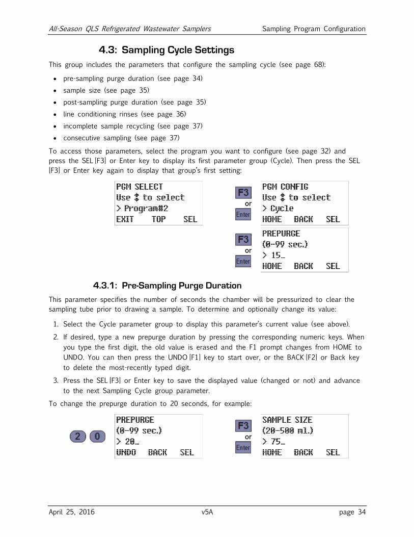
4.3: Sampling Cycle Settings
This group includes the parameters that configure the sampling cycle (see page 68):
pre-sampling purge duration (see page 34)
sample size (see page 35)
post-sampling purge duration (see page 35)
line conditioning rinses (see page 36)
incomplete sample recycling (see page 37)
consecutive sampling (see page 37)
To access those parameters, select the program you want to configure (see page 32) and
press the SEL [F3] or Enter key to display its first parameter group (Cycle). Then press the SEL
[F3] or Enter key again to display that group’s first setting:
or
or
4.3.1: Pre-Sampling Purge Duration
This parameter specifies the number of seconds the chamber will be pressurized to clear the
sampling tube prior to drawing a sample. To determine and optionally change its value:
1. Select the Cycle parameter group to display this parameter’s current value (see above).
2. If desired, type a new prepurge duration by pressing the corresponding numeric keys. When
you type the first digit, the old value is erased and the F1 prompt changes from HOME to
UNDO. You can then press the UNDO [F1] key to start over, or the BACK [F2] or Back key
to delete the most-recently typed digit.
3. Press the SEL [F3] or Enter key to save the displayed value (changed or not) and advance
to the next Sampling Cycle group parameter.
To change the prepurge duration to 20 seconds, for example:
or
All-Season QLS Refrigerated Wastewater Samplers Sampling Program Configuration
April 25, 2016 v5A page 35
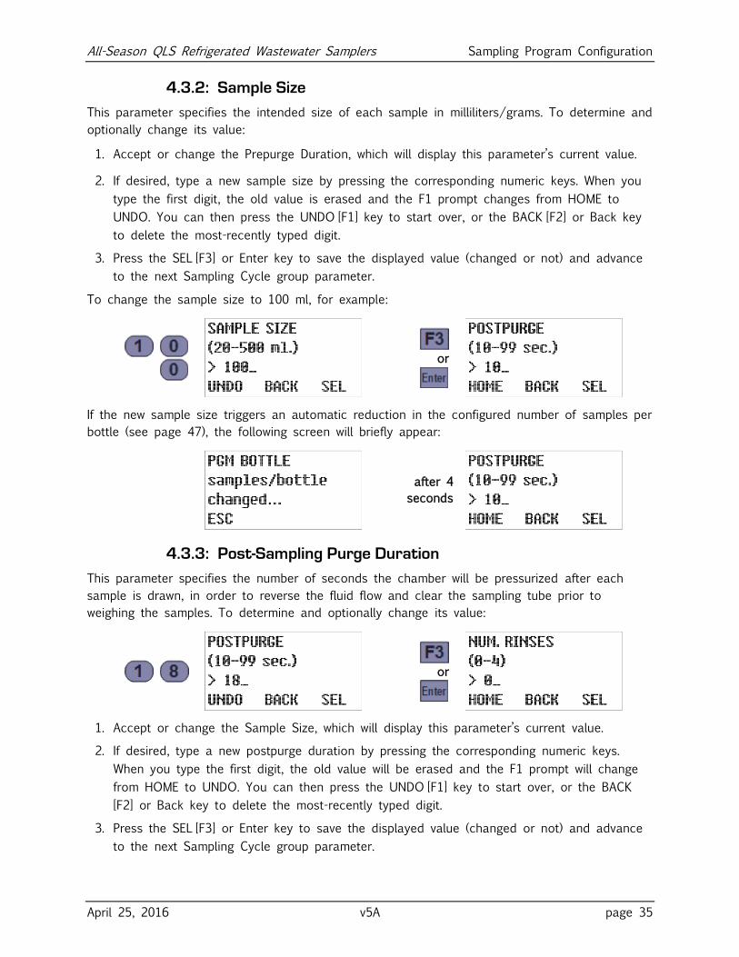
4.3.2: Sample Size
This parameter specifies the intended size of each sample in milliliters/grams. To determine and
optionally change its value:
1. Accept or change the Prepurge Duration, which will display this parameter’s current value.
2. If desired, type a new sample size by pressing the corresponding numeric keys. When you
type the first digit, the old value is erased and the F1 prompt changes from HOME to
UNDO. You can then press the UNDO [F1] key to start over, or the BACK [F2] or Back key
to delete the most-recently typed digit.
3. Press the SEL [F3] or Enter key to save the displayed value (changed or not) and advance
to the next Sampling Cycle group parameter.
To change the sample size to 100 ml, for example:
or
If the new sample size triggers an automatic reduction in the configured number of samples per
bottle (see page 47), the following screen will briefly appear:
after 4
seconds
4.3.3: Post-Sampling Purge Duration
This parameter specifies the number of seconds the chamber will be pressurized after each
sample is drawn, in order to reverse the fluid flow and clear the sampling tube prior to
weighing the samples. To determine and optionally change its value:
or
1. Accept or change the Sample Size, which will display this parameter’s current value.
2. If desired, type a new postpurge duration by pressing the corresponding numeric keys.
When you type the first digit, the old value will be erased and the F1 prompt will change
from HOME to UNDO. You can then press the UNDO [F1] key to start over, or the BACK
[F2] or Back key to delete the most-recently typed digit.
3. Press the SEL [F3] or Enter key to save the displayed value (changed or not) and advance
to the next Sampling Cycle group parameter.
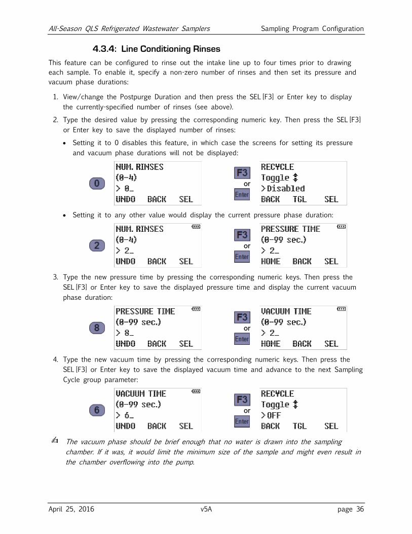
All-Season QLS Refrigerated Wastewater Samplers Sampling Program Configuration
April 25, 2016 v5A page 36
4.3.4: Line Conditioning Rinses
This feature can be configured to rinse out the intake line up to four times prior to drawing
each sample. To enable it, specify a non-zero number of rinses and then set its pressure and
vacuum phase durations:
1. View/change the Postpurge Duration and then press the SEL [F3] or Enter key to display
the currently-specified number of rinses (see above).
2. Type the desired value by pressing the corresponding numeric key. Then press the SEL [F3]
or Enter key to save the displayed number of rinses:
Setting it to 0 disables this feature, in which case the screens for setting its pressure
and vacuum phase durations will not be displayed:
or
Setting it to any other value would display the current pressure phase duration:
or
3. Type the new pressure time by pressing the corresponding numeric keys. Then press the
SEL [F3] or Enter key to save the displayed pressure time and display the current vacuum
phase duration:
or
4. Type the new vacuum time by pressing the corresponding numeric keys. Then press the
SEL [F3] or Enter key to save the displayed vacuum time and advance to the next Sampling
Cycle group parameter:
or
✍ The vacuum phase should be brief enough that no water is drawn into the sampling
chamber. If it was, it would limit the minimum size of the sample and might even result in
the chamber overflowing into the pump.
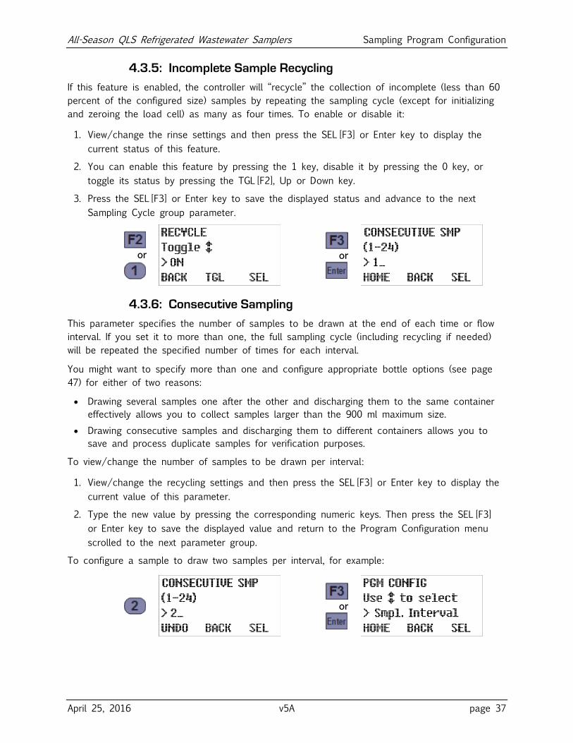
All-Season QLS Refrigerated Wastewater Samplers Sampling Program Configuration
April 25, 2016 v5A page 37
4.3.5: Incomplete Sample Recycling
If this feature is enabled, the controller will “recycle” the collection of incomplete (less than 60
percent of the configured size) samples by repeating the sampling cycle (except for initializing
and zeroing the load cell) as many as four times. To enable or disable it:
1. View/change the rinse settings and then press the SEL [F3] or Enter key to display the
current status of this feature.
2. You can enable this feature by pressing the 1 key, disable it by pressing the 0 key, or
toggle its status by pressing the TGL [F2], Up or Down key.
3. Press the SEL [F3] or Enter key to save the displayed status and advance to the next
Sampling Cycle group parameter.
or
or
4.3.6: Consecutive Sampling
This parameter specifies the number of samples to be drawn at the end of each time or flow
interval. If you set it to more than one, the full sampling cycle (including recycling if needed)
will be repeated the specified number of times for each interval.
You might want to specify more than one and configure appropriate bottle options (see page
47) for either of two reasons:
Drawing several samples one after the other and discharging them to the same container
effectively allows you to collect samples larger than the 900 ml maximum size.
Drawing consecutive samples and discharging them to different containers allows you to
save and process duplicate samples for verification purposes.
To view/change the number of samples to be drawn per interval:
1. View/change the recycling settings and then press the SEL [F3] or Enter key to display the
current value of this parameter.
2. Type the new value by pressing the corresponding numeric keys. Then press the SEL [F3]
or Enter key to save the displayed value and return to the Program Configuration menu
scrolled to the next parameter group.
To configure a sample to draw two samples per interval, for example:
or
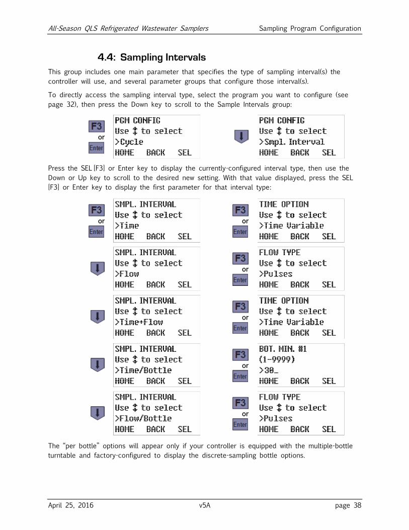
All-Season QLS Refrigerated Wastewater Samplers Sampling Program Configuration
April 25, 2016 v5A page 38
4.4: Sampling Intervals
This group includes one main parameter that specifies the type of sampling interval(s) the
controller will use, and several parameter groups that configure those interval(s).
To directly access the sampling interval type, select the program you want to configure (see
page 32), then press the Down key to scroll to the Sample Intervals group:
or
Press the SEL [F3] or Enter key to display the currently-configured interval type, then use the
Down or Up key to scroll to the desired new setting. With that value displayed, press the SEL
[F3] or Enter key to display the first parameter for that interval type:
or
or
or
or
or
or
The “per bottle” options will appear only if your controller is equipped with the multiple-bottle
turntable and factory-configured to display the discrete-sampling bottle options.
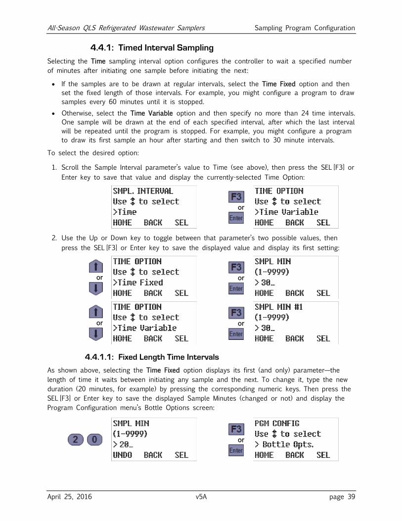
All-Season QLS Refrigerated Wastewater Samplers Sampling Program Configuration
April 25, 2016 v5A page 39
4.4.1: Timed Interval Sampling
Selecting the Time sampling interval option configures the controller to wait a specified number
of minutes after initiating one sample before initiating the next:
If the samples are to be drawn at regular intervals, select the Time Fixed option and then
set the fixed length of those intervals. For example, you might configure a program to draw
samples every 60 minutes until it is stopped.
Otherwise, select the Time Variable option and then specify no more than 24 time intervals.
One sample will be drawn at the end of each specified interval, after which the last interval
will be repeated until the program is stopped. For example, you might configure a program
to draw its first sample an hour after starting and then switch to 30 minute intervals.
To select the desired option:
1. Scroll the Sample Interval parameter’s value to Time (see above), then press the SEL [F3] or
Enter key to save that value and display the currently-selected Time Option:
or
2. Use the Up or Down key to toggle between that parameter’s two possible values, then
press the SEL [F3] or Enter key to save the displayed value and display its first setting:
or
or
or
or
4.4.1.1: Fixed Length Time Intervals
As shown above, selecting the Time Fixed option displays its first (and only) parameter—the
length of time it waits between initiating any sample and the next. To change it, type the new
duration (20 minutes, for example) by pressing the corresponding numeric keys. Then press the
SEL [F3] or Enter key to save the displayed Sample Minutes (changed or not) and display the
Program Configuration menu’s Bottle Options screen:
or
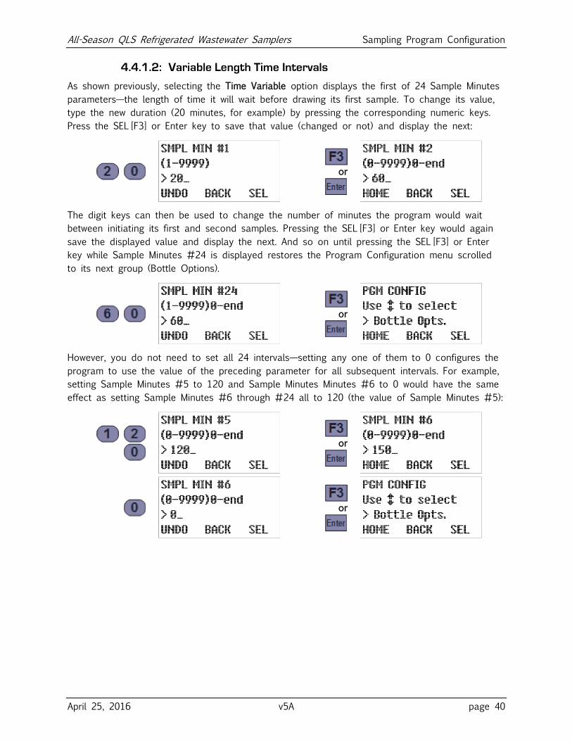
All-Season QLS Refrigerated Wastewater Samplers Sampling Program Configuration
April 25, 2016 v5A page 40
4.4.1.2: Variable Length Time Intervals
As shown previously, selecting the Time Variable option displays the first of 24 Sample Minutes
parameters—the length of time it will wait before drawing its first sample. To change its value,
type the new duration (20 minutes, for example) by pressing the corresponding numeric keys.
Press the SEL [F3] or Enter key to save that value (changed or not) and display the next:
or
The digit keys can then be used to change the number of minutes the program would wait
between initiating its first and second samples. Pressing the SEL [F3] or Enter key would again
save the displayed value and display the next. And so on until pressing the SEL [F3] or Enter
key while Sample Minutes #24 is displayed restores the Program Configuration menu scrolled
to its next group (Bottle Options).
or
However, you do not need to set all 24 intervals—setting any one of them to 0 configures the
program to use the value of the preceding parameter for all subsequent intervals. For example,
setting Sample Minutes #5 to 120 and Sample Minutes Minutes #6 to 0 would have the same
effect as setting Sample Minutes #6 through #24 all to 120 (the value of Sample Minutes #5):
or
or
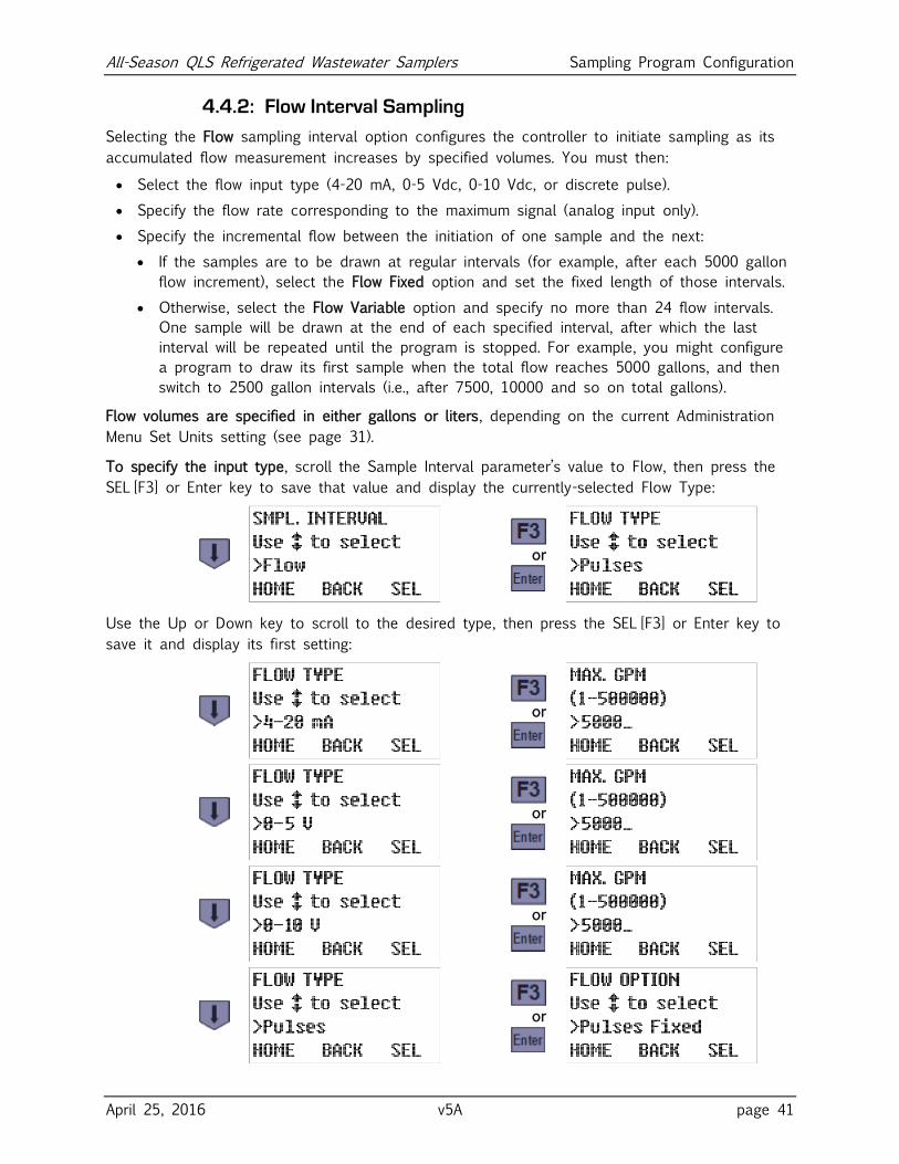
All-Season QLS Refrigerated Wastewater Samplers Sampling Program Configuration
April 25, 2016 v5A page 41
4.4.2: Flow Interval Sampling
Selecting the Flow sampling interval option configures the controller to initiate sampling as its
accumulated flow measurement increases by specified volumes. You must then:
Select the flow input type (4-20 mA, 0-5 Vdc, 0-10 Vdc, or discrete pulse).
Specify the flow rate corresponding to the maximum signal (analog input only).
Specify the incremental flow between the initiation of one sample and the next:
If the samples are to be drawn at regular intervals (for example, after each 5000 gallon
flow increment), select the Flow Fixed option and set the fixed length of those intervals.
Otherwise, select the Flow Variable option and specify no more than 24 flow intervals.
One sample will be drawn at the end of each specified interval, after which the last
interval will be repeated until the program is stopped. For example, you might configure
a program to draw its first sample when the total flow reaches 5000 gallons, and then
switch to 2500 gallon intervals (i.e., after 7500, 10000 and so on total gallons).
Flow volumes are specified in either gallons or liters, depending on the current Administration
Menu Set Units setting (see page 31).
To specify the input type, scroll the Sample Interval parameter’s value to Flow, then press the
SEL [F3] or Enter key to save that value and display the currently-selected Flow Type:
or
Use the Up or Down key to scroll to the desired type, then press the SEL [F3] or Enter key to
save it and display its first setting:
or
or
or
or
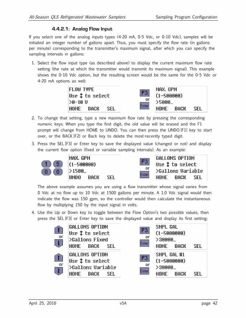
All-Season QLS Refrigerated Wastewater Samplers Sampling Program Configuration
April 25, 2016 v5A page 42
4.4.2.1: Analog Flow Input
If you select one of the analog inputs types (4-20 mA, 0-5 Vdc, or 0-10 Vdc), samples will be
initiated an integer number of gallons apart. Thus, you must specify the flow rate (in gallons
per minute) corresponding to the transmitter’s maximum signal, after which you can specify the
sampling intervals in gallons:
1. Select the flow input type (as described above) to display the current maximum flow rate
setting (the rate at which the transmitter would transmit its maximum signal). This example
shows the 0-10 Vdc option, but the resulting screen would be the same for the 0-5 Vdc or
4-20 mA options as well:
or
2. To change that setting, type a new maximum flow rate by pressing the corresponding
numeric keys. When you type the first digit, the old value will be erased and the F1
prompt will change from HOME to UNDO. You can then press the UNDO [F1] key to start
over, or the BACK [F2] or Back key to delete the most-recently typed digit.
3. Press the SEL [F3] or Enter key to save the displayed value (changed or not) and display
the current flow option (fixed or variable sampling intervals). As an example:
or
The above example assumes you are using a flow transmitter whose signal varies from
0 Vdc at no flow up to 10 Vdc at 1500 gallons per minute. A 1.0 Vdc signal would then
indicate the flow was 150 gpm, so the controller would then calculate the instantaneous
flow by multiplying 150 by the input signal in volts.
4. Use the Up or Down key to toggle between the Flow Option’s two possible values, then
press the SEL [F3] or Enter key to save the displayed value and display its first setting:
or
or
or
or
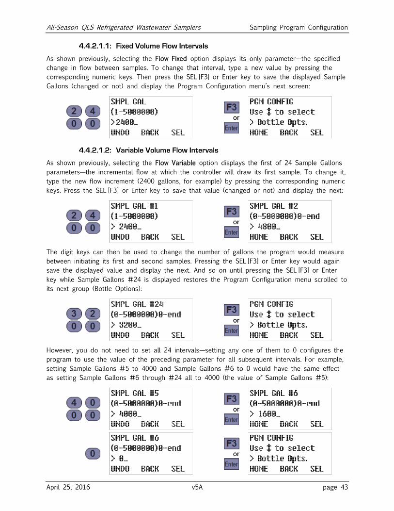
All-Season QLS Refrigerated Wastewater Samplers Sampling Program Configuration
April 25, 2016 v5A page 43
4.4.2.1.1: Fixed Volume Flow Intervals
As shown previously, selecting the Flow Fixed option displays its only parameter—the specified
change in flow between samples. To change that interval, type a new value by pressing the
corresponding numeric keys. Then press the SEL [F3] or Enter key to save the displayed Sample
Gallons (changed or not) and display the Program Configuration menu’s next screen:
or
4.4.2.1.2: Variable Volume Flow Intervals
As shown previously, selecting the Flow Variable option displays the first of 24 Sample Gallons
parameters—the incremental flow at which the controller will draw its first sample. To change it,
type the new flow increment (2400 gallons, for example) by pressing the corresponding numeric
keys. Press the SEL [F3] or Enter key to save that value (changed or not) and display the next:
or
The digit keys can then be used to change the number of gallons the program would measure
between initiating its first and second samples. Pressing the SEL [F3] or Enter key would again
save the displayed value and display the next. And so on until pressing the SEL [F3] or Enter
key while Sample Gallons #24 is displayed restores the Program Configuration menu scrolled to
its next group (Bottle Options):
or
However, you do not need to set all 24 intervals—setting any one of them to 0 configures the
program to use the value of the preceding parameter for all subsequent intervals. For example,
setting Sample Gallons #5 to 4000 and Sample Gallons #6 to 0 would have the same effect
as setting Sample Gallons #6 through #24 all to 4000 (the value of Sample Gallons #5):
or
or
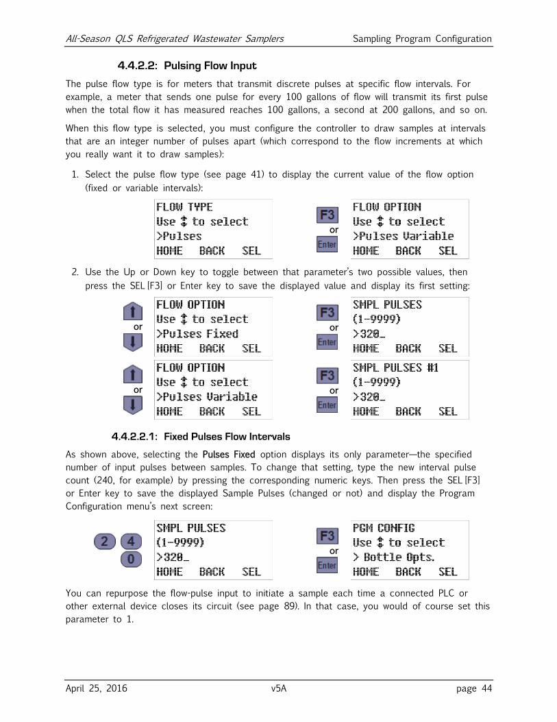
All-Season QLS Refrigerated Wastewater Samplers Sampling Program Configuration
April 25, 2016 v5A page 44
4.4.2.2: Pulsing Flow Input
The pulse flow type is for meters that transmit discrete pulses at specific flow intervals. For
example, a meter that sends one pulse for every 100 gallons of flow will transmit its first pulse
when the total flow it has measured reaches 100 gallons, a second at 200 gallons, and so on.
When this flow type is selected, you must configure the controller to draw samples at intervals
that are an integer number of pulses apart (which correspond to the flow increments at which
you really want it to draw samples):
1. Select the pulse flow type (see page 41) to display the current value of the flow option
(fixed or variable intervals):
or
2. Use the Up or Down key to toggle between that parameter’s two possible values, then
press the SEL [F3] or Enter key to save the displayed value and display its first setting:
or
or
or
or
4.4.2.2.1: Fixed Pulses Flow Intervals
As shown above, selecting the Pulses Fixed option displays its only parameter—the specified
number of input pulses between samples. To change that setting, type the new interval pulse
count (240, for example) by pressing the corresponding numeric keys. Then press the SEL [F3]
or Enter key to save the displayed Sample Pulses (changed or not) and display the Program
Configuration menu’s next screen:
or
You can repurpose the flow-pulse input to initiate a sample each time a connected PLC or
other external device closes its circuit (see page 89). In that case, you would of course set this
parameter to 1.
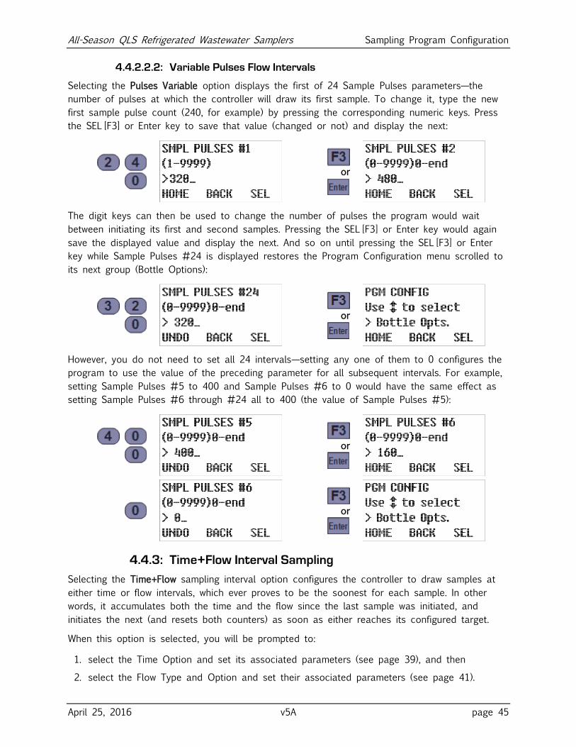
All-Season QLS Refrigerated Wastewater Samplers Sampling Program Configuration
April 25, 2016 v5A page 45
4.4.2.2.2: Variable Pulses Flow Intervals
Selecting the Pulses Variable option displays the first of 24 Sample Pulses parameters—the
number of pulses at which the controller will draw its first sample. To change it, type the new
first sample pulse count (240, for example) by pressing the corresponding numeric keys. Press
the SEL [F3] or Enter key to save that value (changed or not) and display the next:
or
The digit keys can then be used to change the number of pulses the program would wait
between initiating its first and second samples. Pressing the SEL [F3] or Enter key would again
save the displayed value and display the next. And so on until pressing the SEL [F3] or Enter
key while Sample Pulses #24 is displayed restores the Program Configuration menu scrolled to
its next group (Bottle Options):
or
However, you do not need to set all 24 intervals—setting any one of them to 0 configures the
program to use the value of the preceding parameter for all subsequent intervals. For example,
setting Sample Pulses #5 to 400 and Sample Pulses #6 to 0 would have the same effect as
setting Sample Pulses #6 through #24 all to 400 (the value of Sample Pulses #5):
or
or
4.4.3: Time+Flow Interval Sampling
Selecting the Time+Flow sampling interval option configures the controller to draw samples at
either time or flow intervals, which ever proves to be the soonest for each sample. In other
words, it accumulates both the time and the flow since the last sample was initiated, and
initiates the next (and resets both counters) as soon as either reaches its configured target.
When this option is selected, you will be prompted to:
1. select the Time Option and set its associated parameters (see page 39), and then
2. select the Flow Type and Option and set their associated parameters (see page 41).
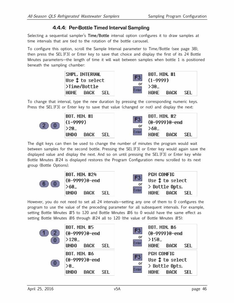
All-Season QLS Refrigerated Wastewater Samplers Sampling Program Configuration
April 25, 2016 v5A page 46
4.4.4: Per-Bottle Timed Interval Sampling
Selecting a sequential sampler’s Time/Bottle interval option configures it to draw samples at
time intervals that are tied to the rotation of the bottle carousel.
To configure this option, scroll the Sample Interval parameter to Time/Bottle (see page 38),
then press the SEL [F3] or Enter key to save that choice and display the first of its 24 Bottle
Minutes parameters—the length of time it will wait between samples when bottle 1 is positioned
beneath the sampling chamber:
or
To change that interval, type the new duration by pressing the corresponding numeric keys.
Press the SEL [F3] or Enter key to save that value (changed or not) and display the next:
or
The digit keys can then be used to change the number of minutes the program would wait
between samples for the second bottle. Pressing the SEL [F3] or Enter key would again save the
displayed value and display the next. And so on until pressing the SEL [F3] or Enter key while
Bottle Minutes #24 is displayed restores the Program Configuration menu scrolled to its next
group (Bottle Options).
or
However, you do not need to set all 24 intervals—setting any one of them to 0 configures the
program to use the value of the preceding parameter for all subsequent intervals. For example,
setting Bottle Minutes #5 to 120 and Bottle Minutes #6 to 0 would have the same effect as
setting Bottle Minutes #6 through #24 all to 120 (the value of Bottle Minutes #5):
or
or
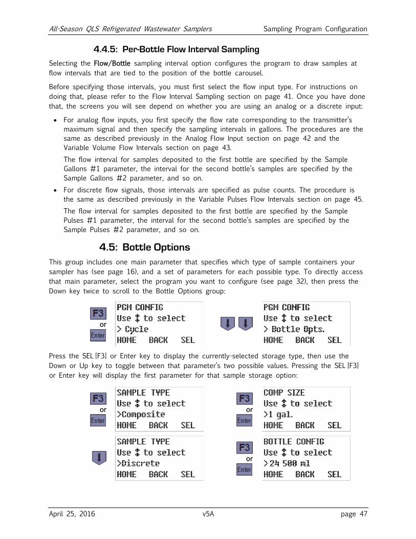
All-Season QLS Refrigerated Wastewater Samplers Sampling Program Configuration
April 25, 2016 v5A page 47
4.4.5: Per-Bottle Flow Interval Sampling
Selecting the Flow/Bottle sampling interval option configures the program to draw samples at
flow intervals that are tied to the position of the bottle carousel.
Before specifying those intervals, you must first select the flow input type. For instructions on
doing that, please refer to the Flow Interval Sampling section on page 41. Once you have done
that, the screens you will see depend on whether you are using an analog or a discrete input:
For analog flow inputs, you first specify the flow rate corresponding to the transmitter’s
maximum signal and then specify the sampling intervals in gallons. The procedures are the
same as described previously in the Analog Flow Input section on page 42 and the
Variable Volume Flow Intervals section on page 43.
The flow interval for samples deposited to the first bottle are specified by the Sample
Gallons #1 parameter, the interval for the second bottle’s samples are specified by the
Sample Gallons #2 parameter, and so on.
For discrete flow signals, those intervals are specified as pulse counts. The procedure is
the same as described previously in the Variable Pulses Flow Intervals section on page 45.
The flow interval for samples deposited to the first bottle are specified by the Sample
Pulses #1 parameter, the interval for the second bottle’s samples are specified by the
Sample Pulses #2 parameter, and so on.
4.5: Bottle Options
This group includes one main parameter that specifies which type of sample containers your
sampler has (see page 16), and a set of parameters for each possible type. To directly access
that main parameter, select the program you want to configure (see page 32), then press the
Down key twice to scroll to the Bottle Options group:
or
Press the SEL [F3] or Enter key to display the currently-selected storage type, then use the
Down or Up key to toggle between that parameter’s two possible values. Pressing the SEL [F3]
or Enter key will display the first parameter for that sample storage option:
or
or
or

All-Season QLS Refrigerated Wastewater Samplers Sampling Program Configuration
April 25, 2016 v5A page 48
4.5.1: Composite Sample Containers
Selecting the Composite bottle option configures the controller to discharge all samples into a
single container, and (as shown above) displays the currently-configured container size. That
size will be shown in either liters or gallons, depending on the current Administration Menu Set
Units setting (see page 31).
Use the Up or Down key to scroll to the container size you are using, then press the SEL [F3]
or Enter key to save that setting and display the number of samples that container is currently
set to receive (note that the maximum is calculated by dividing 90 percent of the container
volume by the previously-set sample size):
or
or
or
or
or
✍ Each unit is generally factory set to display only the bottle sizes its owner purchased, so
the options you see will probably differ from those shown above.
The digit keys can then be used to change the number of samples the program will discharge
to the container before automatically stopping itself. Pressing the SEL [F3] or Enter key will save
the displayed value and display the Program Configuration menu with its next group selected:
or
✍ This setting might be automatically reduced if you subsequently select a smaller container
or increase the configured sample size.
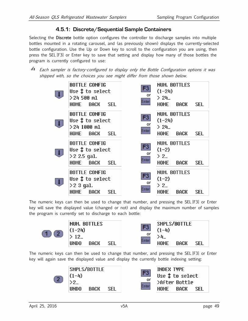
All-Season QLS Refrigerated Wastewater Samplers Sampling Program Configuration
April 25, 2016 v5A page 49
4.5.1: Discrete/Sequential Sample Containers
Selecting the Discrete bottle option configures the controller to discharge samples into multiple
bottles mounted in a rotating carousel, and (as previously shown) displays the currently-selected
bottle configuration. Use the Up or Down key to scroll to the configuration you are using, then
press the SEL [F3] or Enter key to save that setting and display how many of those bottles the
program is currently configured to use:
✍ Each sampler is factory-configured to display only the Bottle Configuration options it was
shipped with, so the choices you see might differ from those shown below.
or
or
or
or
The numeric keys can then be used to change that number, and pressing the SEL [F3] or Enter
key will save the displayed value (changed or not) and display the maximum number of samples
the program is currently set to discharge to each bottle:
or
The numeric keys can then be used to change that number, and pressing the SEL [F3] or Enter
key will again save the displayed value and display the currently bottle indexing setting:
or
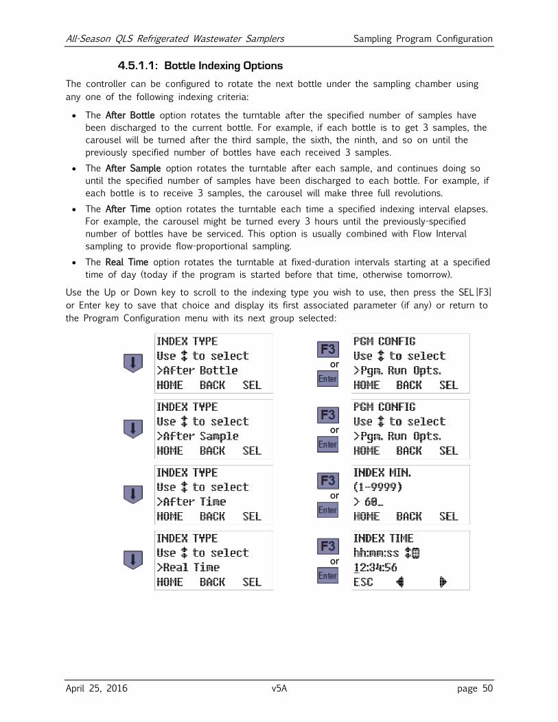
All-Season QLS Refrigerated Wastewater Samplers Sampling Program Configuration
April 25, 2016 v5A page 50
4.5.1.1: Bottle Indexing Options
The controller can be configured to rotate the next bottle under the sampling chamber using
any one of the following indexing criteria:
The After Bottle option rotates the turntable after the specified number of samples have
been discharged to the current bottle. For example, if each bottle is to get 3 samples, the
carousel will be turned after the third sample, the sixth, the ninth, and so on until the
previously specified number of bottles have each received 3 samples.
The After Sample option rotates the turntable after each sample, and continues doing so
until the specified number of samples have been discharged to each bottle. For example, if
each bottle is to receive 3 samples, the carousel will make three full revolutions.
The After Time option rotates the turntable each time a specified indexing interval elapses.
For example, the carousel might be turned every 3 hours until the previously-specified
number of bottles have be serviced. This option is usually combined with Flow Interval
sampling to provide flow-proportional sampling.
The Real Time option rotates the turntable at fixed-duration intervals starting at a specified
time of day (today if the program is started before that time, otherwise tomorrow).
Use the Up or Down key to scroll to the indexing type you wish to use, then press the SEL [F3]
or Enter key to save that choice and display its first associated parameter (if any) or return to
the Program Configuration menu with its next group selected:
or
or
or
or
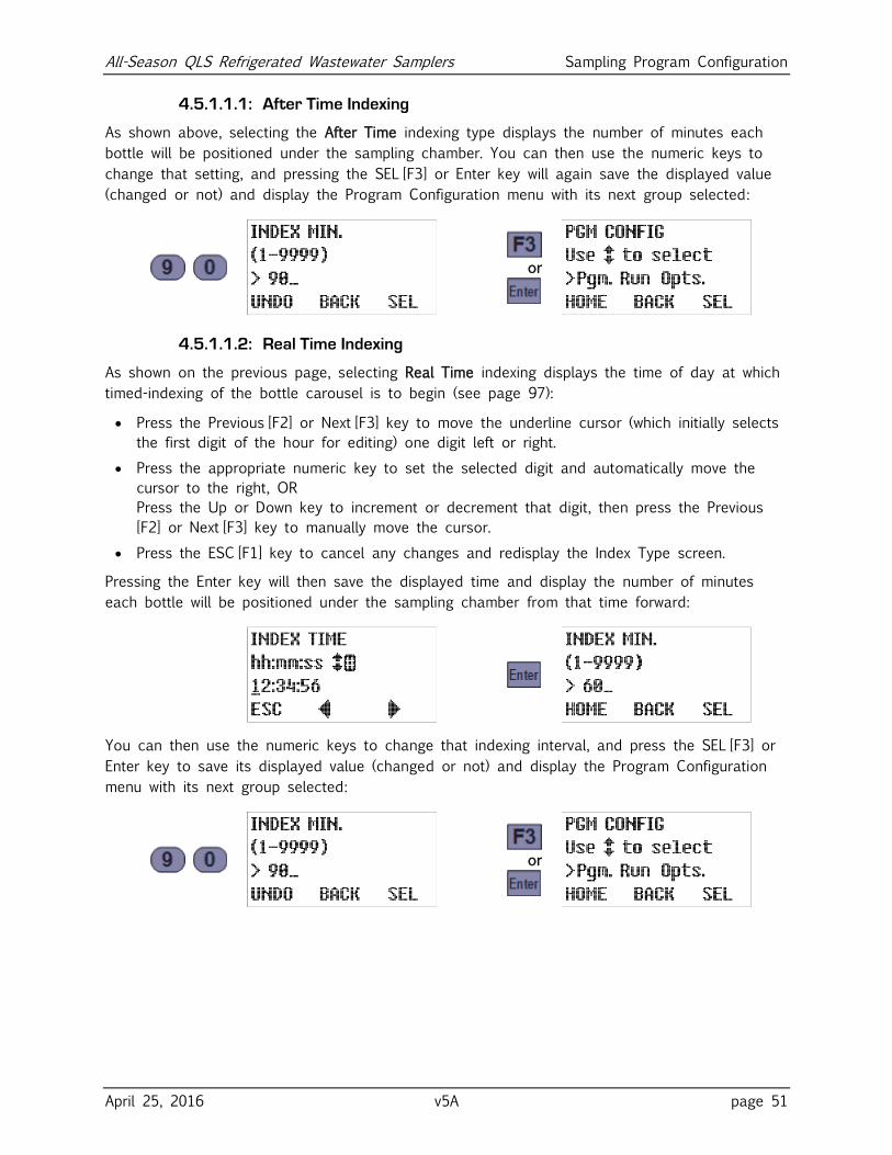
All-Season QLS Refrigerated Wastewater Samplers Sampling Program Configuration
April 25, 2016 v5A page 51
4.5.1.1.1: After Time Indexing
As shown above, selecting the After Time indexing type displays the number of minutes each
bottle will be positioned under the sampling chamber. You can then use the numeric keys to
change that setting, and pressing the SEL [F3] or Enter key will again save the displayed value
(changed or not) and display the Program Configuration menu with its next group selected:
or
4.5.1.1.2: Real Time Indexing
As shown on the previous page, selecting Real Time indexing displays the time of day at which
timed-indexing of the bottle carousel is to begin (see page 97):
Press the Previous [F2] or Next [F3] key to move the underline cursor (which initially selects
the first digit of the hour for editing) one digit left or right.
Press the appropriate numeric key to set the selected digit and automatically move the
cursor to the right, OR
Press the Up or Down key to increment or decrement that digit, then press the Previous
[F2] or Next [F3] key to manually move the cursor.
Press the ESC [F1] key to cancel any changes and redisplay the Index Type screen.
Pressing the Enter key will then save the displayed time and display the number of minutes
each bottle will be positioned under the sampling chamber from that time forward:
You can then use the numeric keys to change that indexing interval, and press the SEL [F3] or
Enter key to save its displayed value (changed or not) and display the Program Configuration
menu with its next group selected:
or
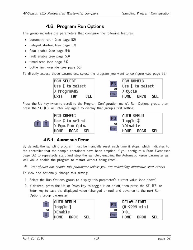
All-Season QLS Refrigerated Wastewater Samplers Sampling Program Configuration
April 25, 2016 v5A page 52
4.6: Program Run Options
This group includes the parameters that configure the following features:
automatic rerun (see page 52)
delayed starting (see page 53)
float enable (see page 54)
fault enable (see page 53)
timed stop (see page 54)
bottle limit override (see page 55)
To directly access those parameters, select the program you want to configure (see page 32):
or
Press the Up key twice to scroll to the Program Configuration menu’s Run Options group, then
press the SEL [F3] or Enter key again to display that group’s first setting:
or
4.6.1: Automatic Rerun
By default, the sampling program must be manually reset each time it stops, which indicates to
the controller that the sample containers have been emptied. If you configure a Start Event (see
page 56) to repeatedly start and stop the sampler, enabling the Automatic Rerun parameter as
well would enable the program to restart without being reset.
✍ You should not enable this parameter unless you are scheduling automatic start events.
To view and optionally change this setting:
1. Select the Run Options group to display this parameter’s current value (see above).
2. If desired, press the Up or Down key to toggle it on or off, then press the SEL [F3] or
Enter key to save the displayed value (changed or not) and advance to the next Run
Options group parameter.
or
or
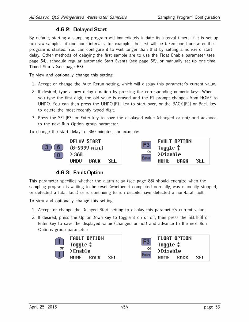
All-Season QLS Refrigerated Wastewater Samplers Sampling Program Configuration
April 25, 2016 v5A page 53
4.6.2: Delayed Start
By default, starting a sampling program will immediately initiate its interval timers. If it is set up
to draw samples at one hour intervals, for example, the first will be taken one hour after the
program is started. You can configure it to wait longer than that by setting a non-zero start
delay. Other methods of delaying the first sample are to use the Float Enable parameter (see
page 54), schedule regular automatic Start Events (see page 56), or manually set up one-time
Timed Starts (see page 63).
To view and optionally change this setting:
1. Accept or change the Auto Rerun setting, which will display this parameter’s current value.
2. If desired, type a new delay duration by pressing the corresponding numeric keys. When
you type the first digit, the old value is erased and the F1 prompt changes from HOME to
UNDO. You can then press the UNDO [F1] key to start over, or the BACK [F2] or Back key
to delete the most-recently typed digit.
3. Press the SEL [F3] or Enter key to save the displayed value (changed or not) and advance
to the next Run Option group parameter.
To change the start delay to 360 minutes, for example:
or
4.6.3: Fault Option
This parameter specifies whether the alarm relay (see page 88) should energize when the
sampling program is waiting to be reset (whether it completed normally, was manually stopped,
or detected a fatal fault) or is continuing to run despite have detected a non-fatal fault.
To view and optionally change this setting:
1. Accept or change the Delayed Start setting to display this parameter’s current value.
2. If desired, press the Up or Down key to toggle it on or off, then press the SEL [F3] or
Enter key to save the displayed value (changed or not) and advance to the next Run
Options group parameter:
or
or
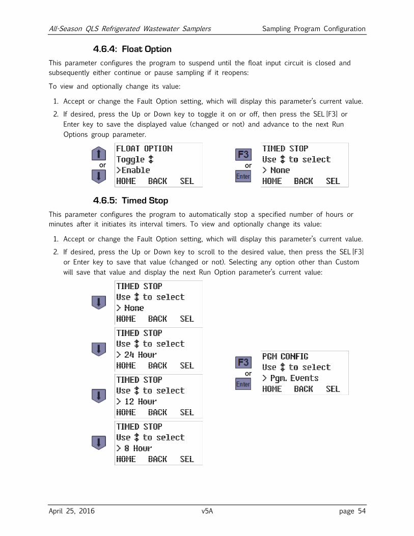
All-Season QLS Refrigerated Wastewater Samplers Sampling Program Configuration
April 25, 2016 v5A page 54
4.6.4: Float Option
This parameter configures the program to suspend until the float input circuit is closed and
subsequently either continue or pause sampling if it reopens:
To view and optionally change its value:
1. Accept or change the Fault Option setting, which will display this parameter’s current value.
2. If desired, press the Up or Down key to toggle it on or off, then press the SEL [F3] or
Enter key to save the displayed value (changed or not) and advance to the next Run
Options group parameter.
or
or
4.6.5: Timed Stop
This parameter configures the program to automatically stop a specified number of hours or
minutes after it initiates its interval timers. To view and optionally change its value:
1. Accept or change the Fault Option setting, which will display this parameter’s current value.
2. If desired, press the Up or Down key to scroll to the desired value, then press the SEL [F3]
or Enter key to save that value (changed or not). Selecting any option other than Custom
will save that value and display the next Run Option parameter’s current value:
or
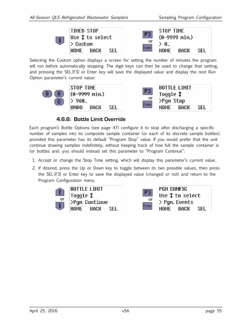
All-Season QLS Refrigerated Wastewater Samplers Sampling Program Configuration
April 25, 2016 v5A page 55
or
Selecting the Custom option displays a screen for setting the number of minutes the program
will run before automatically stopping. The digit keys can then be used to change that setting,
and pressing the SEL [F3] or Enter key will save the displayed value and display the next Run
Option parameter’s current value:
or
4.6.6: Bottle Limit Override
Each program’s Bottle Options (see page 47) configure it to stop after discharging a specific
number of samples into its composite sample container (or each of its discrete sample bottles),
provided this parameter has its default “Program Stop” value. If you would prefer that the unit
continue drawing samples indefinitely, without keeping track of how full the sample container is
(or bottles are), you should instead set this parameter to “Program Continue”:
1. Accept or change the Stop Time setting, which will display this parameter’s current value.
2. If desired, press the Up or Down key to toggle between its two possible values, then press
the SEL [F3] or Enter key to save the displayed value (changed or not) and return to the
Program Configuration menu.
or
or
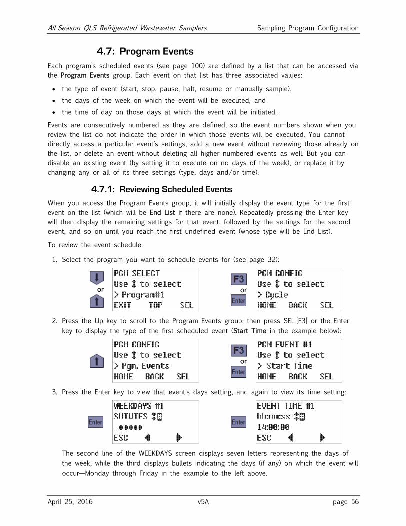
All-Season QLS Refrigerated Wastewater Samplers Sampling Program Configuration
April 25, 2016 v5A page 56
4.7: Program Events
Each program’s scheduled events (see page 100) are defined by a list that can be accessed via
the Program Events group. Each event on that list has three associated values:
the type of event (start, stop, pause, halt, resume or manually sample),
the days of the week on which the event will be executed, and
the time of day on those days at which the event will be initiated.
Events are consecutively numbered as they are defined, so the event numbers shown when you
review the list do not indicate the order in which those events will be executed. You cannot
directly access a particular event’s settings, add a new event without reviewing those already on
the list, or delete an event without deleting all higher numbered events as well. But you can
disable an existing event (by setting it to execute on no days of the week), or replace it by
changing any or all of its three settings (type, days and/or time).
4.7.1: Reviewing Scheduled Events
When you access the Program Events group, it will initially display the event type for the first
event on the list (which will be End List if there are none). Repeatedly pressing the Enter key
will then display the remaining settings for that event, followed by the settings for the second
event, and so on until you reach the first undefined event (whose type will be End List).
To review the event schedule:
1. Select the program you want to schedule events for (see page 32):
or
or
2. Press the Up key to scroll to the Program Events group, then press SEL [F3] or the Enter
key to display the type of the first scheduled event (Start Time in the example below):
or
3. Press the Enter key to view that event’s days setting, and again to view its time setting:
The second line of the WEEKDAYS screen displays seven letters representing the days of
the week, while the third displays bullets indicating the days (if any) on which the event will
occur—Monday through Friday in the example to the left above.
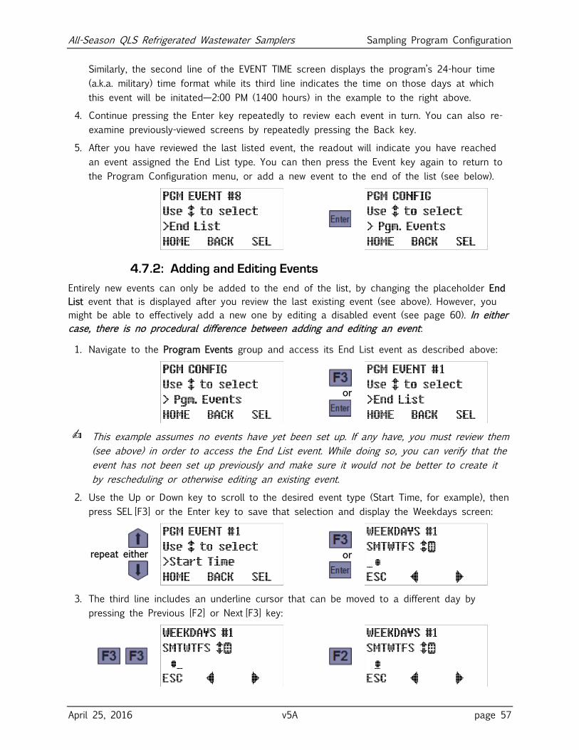
All-Season QLS Refrigerated Wastewater Samplers Sampling Program Configuration
April 25, 2016 v5A page 57
Similarly, the second line of the EVENT TIME screen displays the program’s 24-hour time
(a.k.a. military) time format while its third line indicates the time on those days at which
this event will be initated—2:00 PM (1400 hours) in the example to the right above.
4. Continue pressing the Enter key repeatedly to review each event in turn. You can also re-
examine previously-viewed screens by repeatedly pressing the Back key.
5. After you have reviewed the last listed event, the readout will indicate you have reached
an event assigned the End List type. You can then press the Event key again to return to
the Program Configuration menu, or add a new event to the end of the list (see below).
4.7.2: Adding and Editing Events
Entirely new events can only be added to the end of the list, by changing the placeholder End
List event that is displayed after you review the last existing event (see above). However, you
might be able to effectively add a new one by editing a disabled event (see page 60). In either
case, there is no procedural difference between adding and editing an event:
1. Navigate to the Program Events group and access its End List event as described above:
or
✍ This example assumes no events have yet been set up. If any have, you must review them
(see above) in order to access the End List event. While doing so, you can verify that the
event has not been set up previously and make sure it would not be better to create it
by rescheduling or otherwise editing an existing event.
2. Use the Up or Down key to scroll to the desired event type (Start Time, for example), then
press SEL [F3] or the Enter key to save that selection and display the Weekdays screen:
repeat either
or
3. The third line includes an underline cursor that can be moved to a different day by
pressing the Previous [F2] or Next [F3] key:
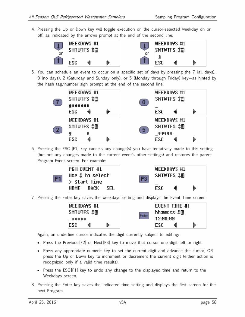
All-Season QLS Refrigerated Wastewater Samplers Sampling Program Configuration
April 25, 2016 v5A page 58
4. Pressing the Up or Down key will toggle execution on the cursor-selected weekday on or
off, as indicated by the arrows prompt at the end of the second line:
or
or
5. You can schedule an event to occur on a specific set of days by pressing the 7 (all days),
0 (no days), 2 (Saturday and Sunday only), or 5 (Monday through Friday) key—as hinted by
the hash tag/number sign prompt at the end of the second line:
6. Pressing the ESC [F1] key cancels any change(s) you have tentatively made to this setting
(but not any changes made to the current event’s other settings) and restores the parent
Program Event screen. For example:
7. Pressing the Enter key saves the weekdays setting and displays the Event Time screen:
Again, an underline cursor indicates the digit currently subject to editing:
Press the Previous [F2] or Next [F3] key to move that cursor one digit left or right.
Press any appropriate numeric key to set the current digit and advance the cursor, OR
press the Up or Down key to increment or decrement the current digit (either action is
recognized only if a valid time results).
Press the ESC [F1] key to undo any change to the displayed time and return to the
Weekdays screen.
8. Pressing the Enter key saves the indicated time setting and displays the first screen for the
next Program.

All-Season QLS Refrigerated Wastewater Samplers Sampling Program Configuration
April 25, 2016 v5A page 59
4.7.3: Deleting Events
Events can be deleted only from the end of the list—by reviewing the settings for each event
you want to keep and then changing the type of the first one you want to delete to End List.
✍ An event could effectively be removed from the middle of the list by disabling it, as
described in the next topic.
For example, if there were eight listed events and you wanted to delete all but the first two:
1. Access the Program Events group as described above:
or
2. Press the Enter key repeatedly until the first Event #3 screen appears, then use the Up or
Down key to scroll to the End List event type:
repeat until
repeat either
3. Finally, press SEL [F3] or the Enter key to delete this and any higher-numbered events:
or
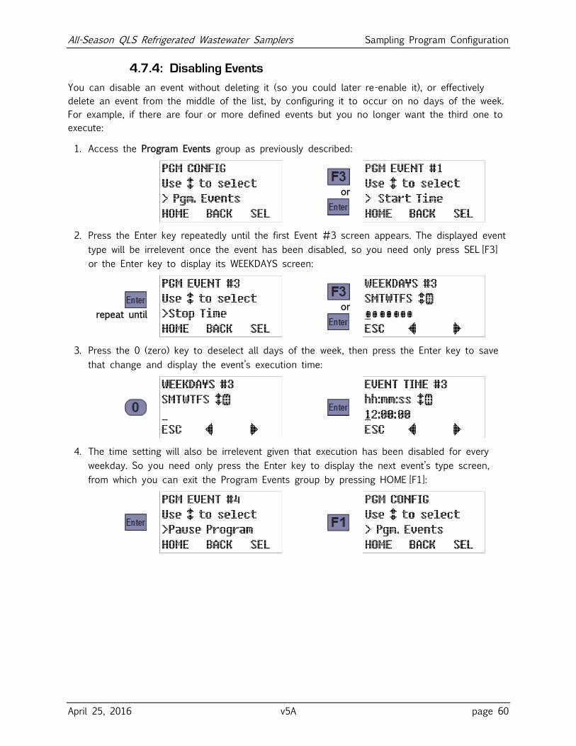
All-Season QLS Refrigerated Wastewater Samplers Sampling Program Configuration
April 25, 2016 v5A page 60
4.7.4: Disabling Events
You can disable an event without deleting it (so you could later re-enable it), or effectively
delete an event from the middle of the list, by configuring it to occur on no days of the week.
For example, if there are four or more defined events but you no longer want the third one to
execute:
1. Access the Program Events group as previously described:
or
2. Press the Enter key repeatedly until the first Event #3 screen appears. The displayed event
type will be irrelevent once the event has been disabled, so you need only press SEL [F3]
or the Enter key to display its WEEKDAYS screen:
repeat until
or
3. Press the 0 (zero) key to deselect all days of the week, then press the Enter key to save
that change and display the event’s execution time:
4. The time setting will also be irrelevent given that execution has been disabled for every
weekday. So you need only press the Enter key to display the next event’s type screen,
from which you can exit the Program Events group by pressing HOME [F1]:
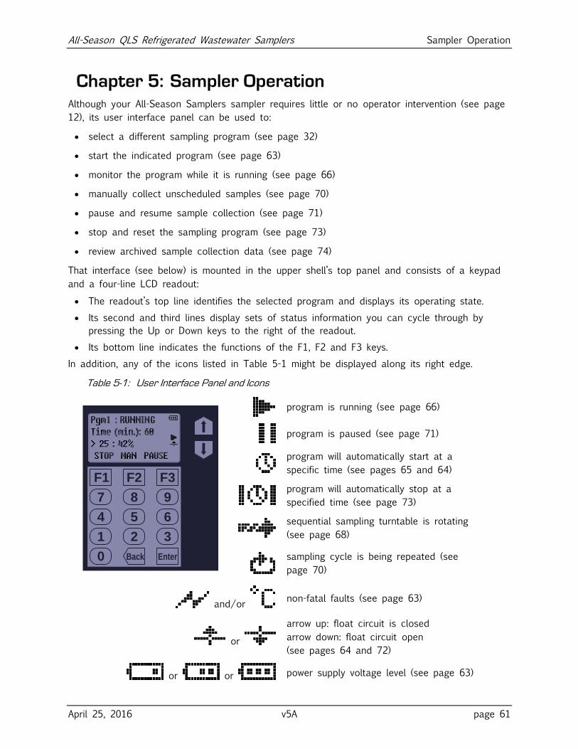
All-Season QLS Refrigerated Wastewater Samplers Sampler Operation
April 25, 2016 v5A page 61
Chapter 5: Sampler Operation Although your All-Season Samplers sampler requires little or no operator intervention (see page
12), its user interface panel can be used to:
select a different sampling program (see page 32)
start the indicated program (see page 63)
monitor the program while it is running (see page 66)
manually collect unscheduled samples (see page 70)
pause and resume sample collection (see page 71)
stop and reset the sampling program (see page 73)
review archived sample collection data (see page 74)
That interface (see below) is mounted in the upper shell’s top panel and consists of a keypad
and a four-line LCD readout:
The readout’s top line identifies the selected program and displays its operating state.
Its second and third lines display sets of status information you can cycle through by
pressing the Up or Down keys to the right of the readout.
Its bottom line indicates the functions of the F1, F2 and F3 keys.
In addition, any of the icons listed in Table 5-1 might be displayed along its right edge.
Table 5-1: User Interface Panel and Icons
F1
21 3
54 6
87 9
0
F2 F3
Back Enter
program is running (see page 66)
program is paused (see page 71)
program will automatically start at a
specific time (see pages 65 and 64)
program will automatically stop at a
specified time (see page 73)
sequential sampling turntable is rotating
(see page 68)
sampling cycle is being repeated (see
page 70)
and/or non-fatal faults (see page 63)
or
arrow up: float circuit is closed
arrow down: float circuit open
(see pages 64 and 72)
or or power supply voltage level (see page 63)
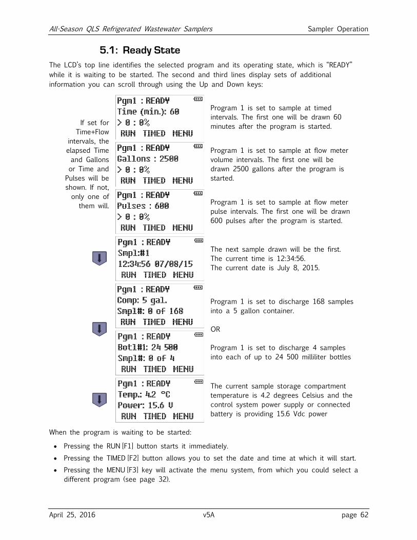
All-Season QLS Refrigerated Wastewater Samplers Sampler Operation
April 25, 2016 v5A page 62
5.1: Ready State
The LCD’s top line identifies the selected program and its operating state, which is “READY”
while it is waiting to be started. The second and third lines display sets of additional
information you can scroll through using the Up and Down keys:
If set for
Time+Flow
intervals, the
elapsed Time
and Gallons
or Time and
Pulses will be
shown. If not,
only one of
them will.
Program 1 is set to sample at timed
intervals. The first one will be drawn 60
minutes after the program is started.
Program 1 is set to sample at flow meter
volume intervals. The first one will be
drawn 2500 gallons after the program is
started.
Program 1 is set to sample at flow meter
pulse intervals. The first one will be drawn
600 pulses after the program is started.
The next sample drawn will be the first.
The current time is 12:34:56.
The current date is July 8, 2015.
Program 1 is set to discharge 168 samples
into a 5 gallon container.
OR
Program 1 is set to discharge 4 samples
into each of up to 24 500 milliliter bottles
The current sample storage compartment
temperature is 4.2 degrees Celsius and the
control system power supply or connected
battery is providing 15.6 Vdc power
When the program is waiting to be started:
Pressing the RUN [F1] button starts it immediately.
Pressing the TIMED [F2] button allows you to set the date and time at which it will start.
Pressing the MENU [F3] key will activate the menu system, from which you could select a
different program (see page 32).
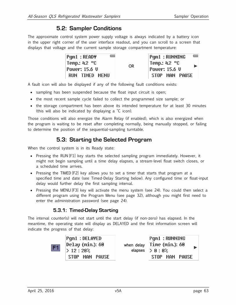
All-Season QLS Refrigerated Wastewater Samplers Sampler Operation
April 25, 2016 v5A page 63
5.2: Sampler Conditions
The approximate control system power supply voltage is always indicated by a battery icon
in the upper right corner of the user interface readout, and you can scroll to a screen that
displays that voltage and the current sample storage compartment temperature:
OR
A fault icon will also be displayed if any of the following fault conditions exists:
sampling has been suspended because the float input circuit is open;
the most recent sample cycle failed to collect the programmed size sample; or
the storage compartment has been above its intended temperature for at least 30 minutes
(this will also be indicated by displaying a °C icon).
Those conditions will also energize the Alarm Relay (if enabled), which is also energized when
the program is waiting to be reset after completing normally, being manually stopped, or failing
to determine the position of the sequential-sampling turntable.
5.3: Starting the Selected Program
When the control system is in its Ready state:
Pressing the RUN [F1] key starts the selected sampling program immediately. However, it
might not begin sampling until a time delay elapses, a stream-level float switch closes, or
a scheduled time arrives.
Pressing the TIMED [F2] key allows you to set a timer that starts that program at a
specified time and date (see Timed-Delay Starting below). Any configured time or float-input
delay would further delay the first sampling interval.
Pressing the MENU [F3] key will activate the menu system (see 24). You could then select a
different program using the Program Menu (see page 32), although you might first need to
enter the administration password (see page 24).
5.3.1: Timed-Delay Starting
The interval counter(s) will not start until the start delay (if non-zero) has elapsed. In the
meantime, the operating state will display as DELAYED and the first information screen will
indicate the progress of that delay:
when delay
elapses
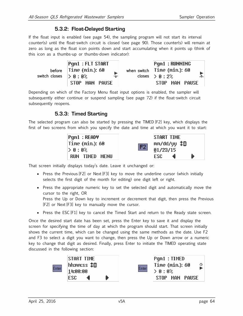
All-Season QLS Refrigerated Wastewater Samplers Sampler Operation
April 25, 2016 v5A page 64
5.3.2: Float-Delayed Starting
If the float input is enabled (see page 54), the sampling program will not start its interval
counter(s) until the float-switch circuit is closed (see page 90). Those counter(s) will remain at
zero as long as the float icon points down and start accumulating when it points up (think of
this icon as a thumbs-up or thumbs-down indicator):
before
switch closes
when switch
closes
Depending on which of the Factory Menu float input options is enabled, the sampler will
subsequently either continue or suspend sampling (see page 72) if the float-switch circuit
subsequently reopens.
5.3.3: Timed Starting
The selected program can also be started by pressing the TIMED [F2] key, which displays the
first of two screens from which you specify the date and time at which you want it to start:
That screen initially displays today’s date. Leave it unchanged or:
Press the Previous [F2] or Next [F3] key to move the underline cursor (which initially
selects the first digit of the month for editing) one digit left or right.
Press the appropriate numeric key to set the selected digit and automatically move the
cursor to the right, OR
Press the Up or Down key to increment or decrement that digit, then press the Previous
[F2] or Next [F3] key to manually move the cursor.
Press the ESC [F1] key to cancel the Timed Start and return to the Ready state screen.
Once the desired start date has been set, press the Enter key to save it and display the
screen for specifying the time of day at which the program should start. That screen initially
shows the current time, which can be changed using the same methods as the date. Use F2
and F3 to select a digit you want to change, then press the Up or Down arrow or a numeric
key to change that digit as desired. Finally, press Enter to initiate the TIMED operating state
discussed in the following section:
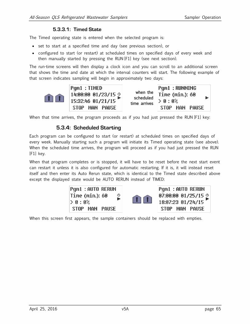
All-Season QLS Refrigerated Wastewater Samplers Sampler Operation
April 25, 2016 v5A page 65
5.3.3.1: Timed State
The Timed operating state is entered when the selected program is:
set to start at a specified time and day (see previous section), or
configured to start (or restart) at scheduled times on specified days of every week and
then manually started by pressing the RUN [F1] key (see next section).
The run-time screens will then display a clock icon and you can scroll to an additional screen
that shows the time and date at which the interval counters will start. The following example of
that screen indicates sampling will begin in approximately two days:
when the
scheduled
time arrives
When that time arrives, the program proceeds as if you had just pressed the RUN [F1] key:
5.3.4: Scheduled Starting
Each program can be configured to start (or restart) at scheduled times on specified days of
every week. Manually starting such a program will initiate its Timed operating state (see above).
When the scheduled time arrives, the program will proceed as if you had just pressed the RUN
[F1] key.
When that program completes or is stopped, it will have to be reset before the next start event
can restart it unless it is also configured for automatic restarting. If it is, it will instead reset
itself and then enter its Auto Rerun state, which is identical to the Timed state described above
except the displayed state would be AUTO RERUN instead of TIMED:
When this screen first appears, the sample containers should be replaced with empties.
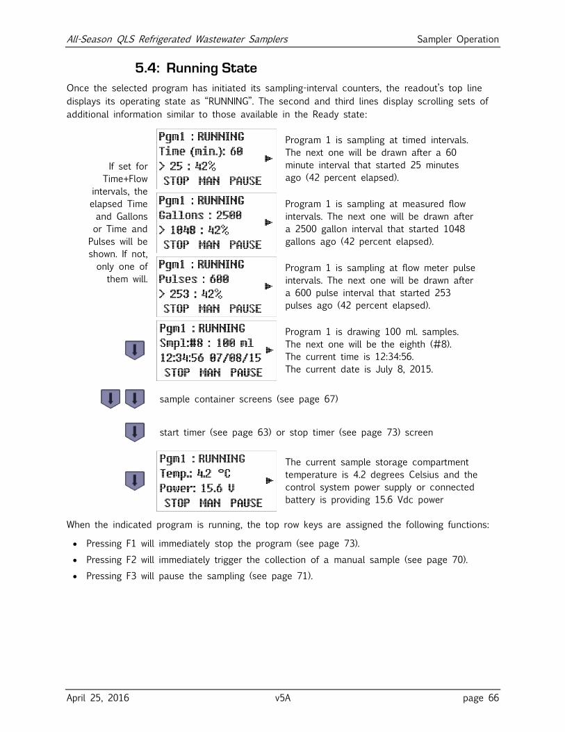
All-Season QLS Refrigerated Wastewater Samplers Sampler Operation
April 25, 2016 v5A page 66
5.4: Running State
Once the selected program has initiated its sampling-interval counters, the readout’s top line
displays its operating state as “RUNNING”. The second and third lines display scrolling sets of
additional information similar to those available in the Ready state:
If set for
Time+Flow
intervals, the
elapsed Time
and Gallons
or Time and
Pulses will be
shown. If not,
only one of
them will.
Program 1 is sampling at timed intervals.
The next one will be drawn after a 60
minute interval that started 25 minutes
ago (42 percent elapsed).
Program 1 is sampling at measured flow
intervals. The next one will be drawn after
a 2500 gallon interval that started 1048
gallons ago (42 percent elapsed).
Program 1 is sampling at flow meter pulse
intervals. The next one will be drawn after
a 600 pulse interval that started 253
pulses ago (42 percent elapsed).
Program 1 is drawing 100 ml. samples.
The next one will be the eighth (#8).
The current time is 12:34:56.
The current date is July 8, 2015.
sample container screens (see page 67)
start timer (see page 63) or stop timer (see page 73) screen
The current sample storage compartment
temperature is 4.2 degrees Celsius and the
control system power supply or connected
battery is providing 15.6 Vdc power
When the indicated program is running, the top row keys are assigned the following functions:
Pressing F1 will immediately stop the program (see page 73).
Pressing F2 will immediately trigger the collection of a manual sample (see page 70).
Pressing F3 will pause the sampling (see page 71).
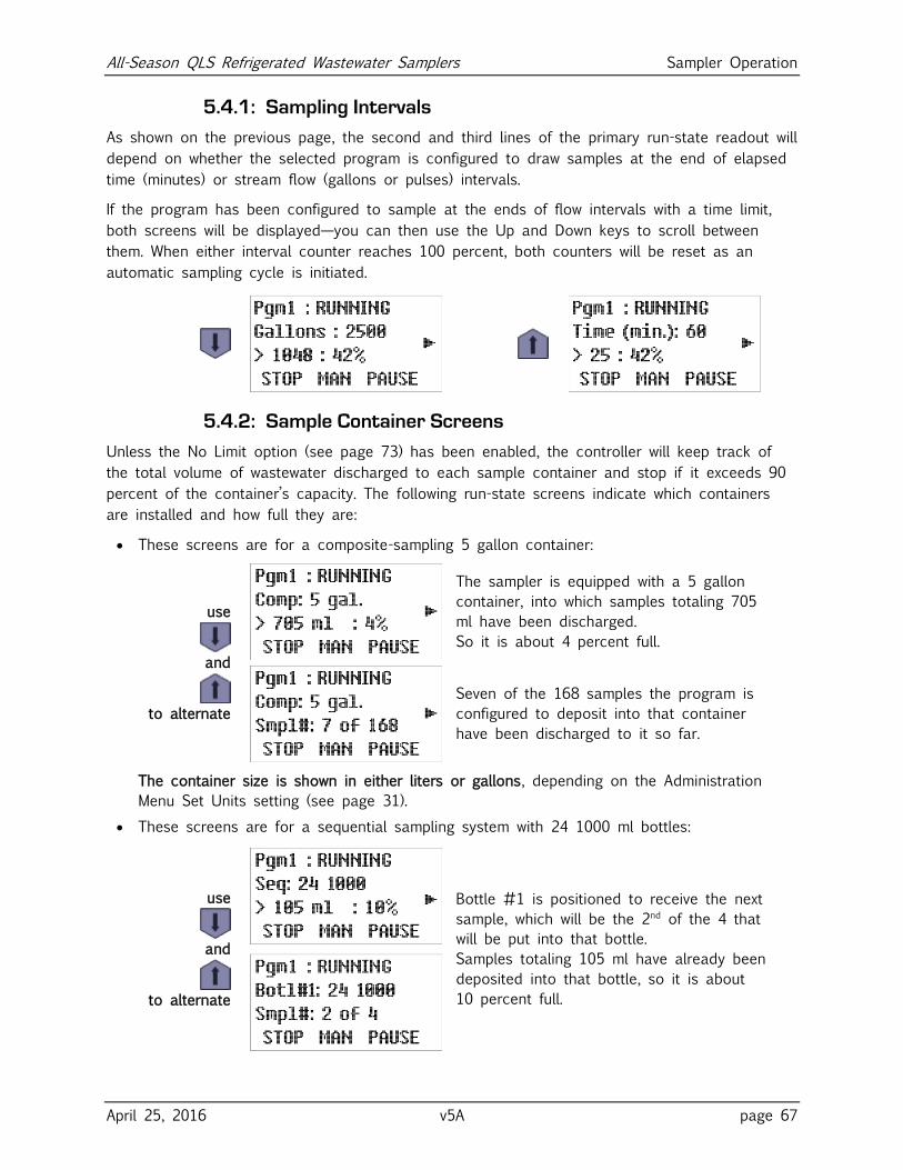
All-Season QLS Refrigerated Wastewater Samplers Sampler Operation
April 25, 2016 v5A page 67
5.4.1: Sampling Intervals
As shown on the previous page, the second and third lines of the primary run-state readout will
depend on whether the selected program is configured to draw samples at the end of elapsed
time (minutes) or stream flow (gallons or pulses) intervals.
If the program has been configured to sample at the ends of flow intervals with a time limit,
both screens will be displayed—you can then use the Up and Down keys to scroll between
them. When either interval counter reaches 100 percent, both counters will be reset as an
automatic sampling cycle is initiated.
5.4.2: Sample Container Screens
Unless the No Limit option (see page 73) has been enabled, the controller will keep track of
the total volume of wastewater discharged to each sample container and stop if it exceeds 90
percent of the container’s capacity. The following run-state screens indicate which containers
are installed and how full they are:
These screens are for a composite-sampling 5 gallon container:
use
and
to alternate
The sampler is equipped with a 5 gallon
container, into which samples totaling 705
ml have been discharged.
So it is about 4 percent full.
Seven of the 168 samples the program is
configured to deposit into that container
have been discharged to it so far.
The container size is shown in either liters or gallons, depending on the Administration
Menu Set Units setting (see page 31).
These screens are for a sequential sampling system with 24 1000 ml bottles:
use
and
to alternate
Bottle #1 is positioned to receive the next
sample, which will be the 2nd of the 4 that
will be put into that bottle.
Samples totaling 105 ml have already been
deposited into that bottle, so it is about
10 percent full.
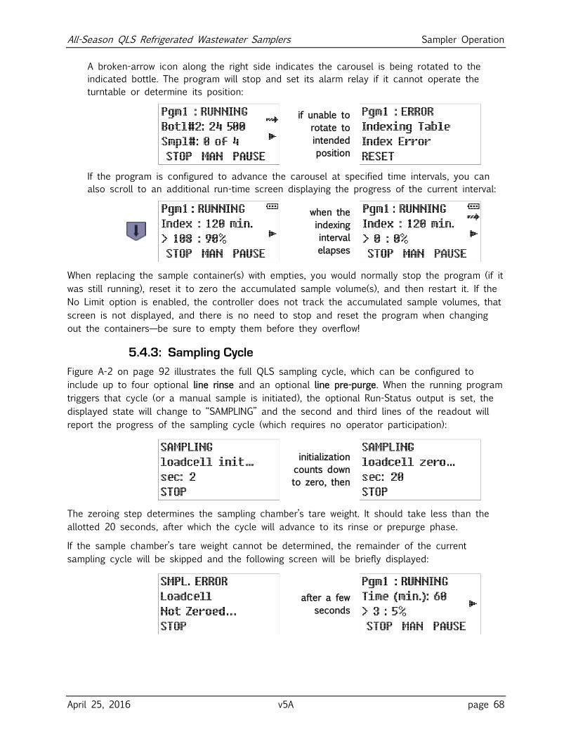
All-Season QLS Refrigerated Wastewater Samplers Sampler Operation
April 25, 2016 v5A page 68
A broken-arrow icon along the right side indicates the carousel is being rotated to the
indicated bottle. The program will stop and set its alarm relay if it cannot operate the
turntable or determine its position:
if unable to
rotate to
intended
position
If the program is configured to advance the carousel at specified time intervals, you can
also scroll to an additional run-time screen displaying the progress of the current interval:
when the
indexing
interval
elapses
When replacing the sample container(s) with empties, you would normally stop the program (if it
was still running), reset it to zero the accumulated sample volume(s), and then restart it. If the
No Limit option is enabled, the controller does not track the accumulated sample volumes, that
screen is not displayed, and there is no need to stop and reset the program when changing
out the containers—be sure to empty them before they overflow!
5.4.3: Sampling Cycle
Figure A-2 on page 92 illustrates the full QLS sampling cycle, which can be configured to
include up to four optional line rinse and an optional line pre-purge. When the running program
triggers that cycle (or a manual sample is initiated), the optional Run-Status output is set, the
displayed state will change to “SAMPLING” and the second and third lines of the readout will
report the progress of the sampling cycle (which requires no operator participation):
initialization
counts down
to zero, then
The zeroing step determines the sampling chamber’s tare weight. It should take less than the
allotted 20 seconds, after which the cycle will advance to its rinse or prepurge phase.
If the sample chamber’s tare weight cannot be determined, the remainder of the current
sampling cycle will be skipped and the following screen will be briefly displayed:
after a few
seconds
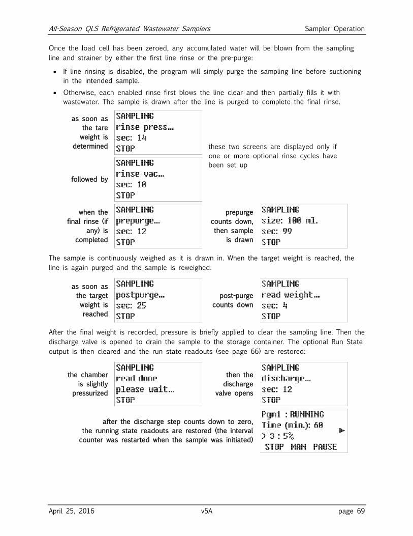
All-Season QLS Refrigerated Wastewater Samplers Sampler Operation
April 25, 2016 v5A page 69
Once the load cell has been zeroed, any accumulated water will be blown from the sampling
line and strainer by either the first line rinse or the pre-purge:
If line rinsing is disabled, the program will simply purge the sampling line before suctioning
in the intended sample.
Otherwise, each enabled rinse first blows the line clear and then partially fills it with
wastewater. The sample is drawn after the line is purged to complete the final rinse.
as soon as
the tare
weight is
determined these two screens are displayed only if
one or more optional rinse cycles have
been set up
followed by
when the
final rinse (if
any) is
completed
prepurge
counts down,
then sample
is drawn
The sample is continuously weighed as it is drawn in. When the target weight is reached, the
line is again purged and the sample is reweighed:
as soon as
the target
weight is
reached
post-purge
counts down
After the final weight is recorded, pressure is briefly applied to clear the sampling line. Then the
discharge valve is opened to drain the sample to the storage container. The optional Run State
output is then cleared and the run state readouts (see page 66) are restored:
the chamber
is slightly
pressurized
then the
discharge
valve opens
after the discharge step counts down to zero,
the running state readouts are restored (the interval
counter was restarted when the sample was initiated)
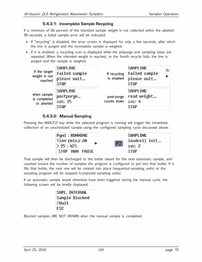
All-Season QLS Refrigerated Wastewater Samplers Sampler Operation
April 25, 2016 v5A page 70
5.4.3.1: Incomplete Sample Recycling
If a minimum of 60 percent of the intended sample weight is not collected within the allotted
99 seconds, a failed sample error will be indicated:
If “recycling” is disabled, the error screen is displayed for only a few seconds, after which
the line is purged and the incomplete sample is weighed.
If it is enabled, a recycling icon is displayed while the prepurge and sampling steps are
repeated. When the intended weight is reached, or the fourth recycle fails, the line is
purged and the sample is weighed.
if the target
weight is not
reached
If recycling
is enabled
when sample
is completed
or aborted
post-purge
counts down
5.4.3.2: Manual Sampling
Pressing the MAN [F2] key while the selected program is running will trigger the immediate
collection of an unscheduled sample using the configured sampling cycle discussed above:
That sample will then be discharged to the bottle meant for the next automatic sample, and
counted toward the number of samples the program is configured to put into that bottle. If it
fills that bottle, the next one will be rotated into place (sequential-sampling units) or the
sampling program will be stopped (composite-sampling units).
If an automatic sample would otherwise have been triggered during the manual cycle, the
following screen will be briefly displayed:
Blocked samples ARE NOT DRAWN when the manual sample is completed.
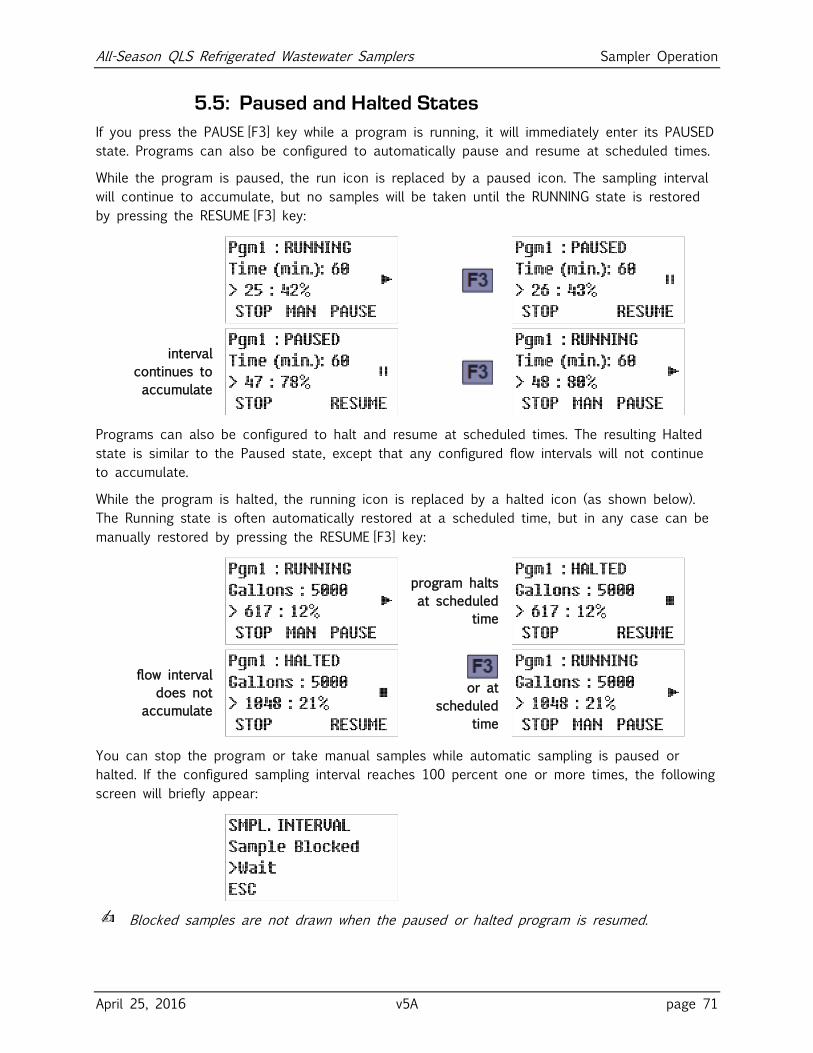
All-Season QLS Refrigerated Wastewater Samplers Sampler Operation
April 25, 2016 v5A page 71
5.5: Paused and Halted States
If you press the PAUSE [F3] key while a program is running, it will immediately enter its PAUSED
state. Programs can also be configured to automatically pause and resume at scheduled times.
While the program is paused, the run icon is replaced by a paused icon. The sampling interval
will continue to accumulate, but no samples will be taken until the RUNNING state is restored
by pressing the RESUME [F3] key:
interval
continues to
accumulate
Programs can also be configured to halt and resume at scheduled times. The resulting Halted
state is similar to the Paused state, except that any configured flow intervals will not continue
to accumulate.
While the program is halted, the running icon is replaced by a halted icon (as shown below).
The Running state is often automatically restored at a scheduled time, but in any case can be
manually restored by pressing the RESUME [F3] key:
program halts
at scheduled
time
flow interval
does not
accumulate
or at
scheduled
time
You can stop the program or take manual samples while automatic sampling is paused or
halted. If the configured sampling interval reaches 100 percent one or more times, the following
screen will briefly appear:
✍ Blocked samples are not drawn when the paused or halted program is resumed.
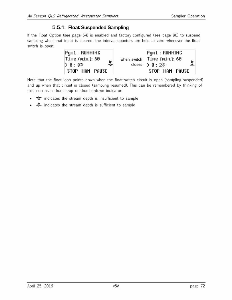
All-Season QLS Refrigerated Wastewater Samplers Sampler Operation
April 25, 2016 v5A page 72
5.5.1: Float Suspended Sampling
If the Float Option (see page 54) is enabled and factory-configured (see page 90) to suspend
sampling when that input is cleared, the interval counters are held at zero whenever the float
switch is open:
when switch
closes
Note that the float icon points down when the float-switch circuit is open (sampling suspended)
and up when that circuit is closed (sampling resumed). This can be remembered by thinking of
this icon as a thumbs-up or thumbs-down indicator:
indicates the stream depth is insufficient to sample
indicates the stream depth is sufficient to sample
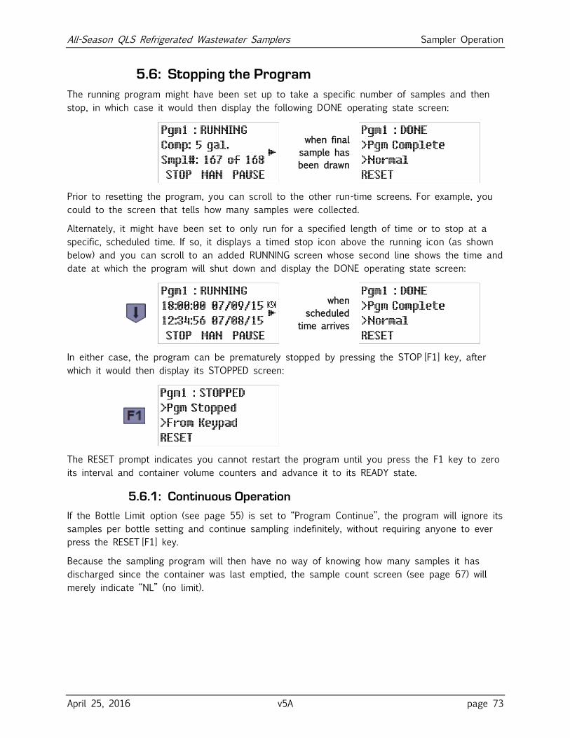
All-Season QLS Refrigerated Wastewater Samplers Sampler Operation
April 25, 2016 v5A page 73
5.6: Stopping the Program
The running program might have been set up to take a specific number of samples and then
stop, in which case it would then display the following DONE operating state screen:
when final
sample has
been drawn
Prior to resetting the program, you can scroll to the other run-time screens. For example, you
could to the screen that tells how many samples were collected.
Alternately, it might have been set to only run for a specified length of time or to stop at a
specific, scheduled time. If so, it displays a timed stop icon above the running icon (as shown
below) and you can scroll to an added RUNNING screen whose second line shows the time and
date at which the program will shut down and display the DONE operating state screen:
when
scheduled
time arrives
In either case, the program can be prematurely stopped by pressing the STOP [F1] key, after
which it would then display its STOPPED screen:
The RESET prompt indicates you cannot restart the program until you press the F1 key to zero
its interval and container volume counters and advance it to its READY state.
5.6.1: Continuous Operation
If the Bottle Limit option (see page 55) is set to “Program Continue”, the program will ignore its
samples per bottle setting and continue sampling indefinitely, without requiring anyone to ever
press the RESET [F1] key.
Because the sampling program will then have no way of knowing how many samples it has
discharged since the container was last emptied, the sample count screen (see page 67) will
merely indicate “NL” (no limit).
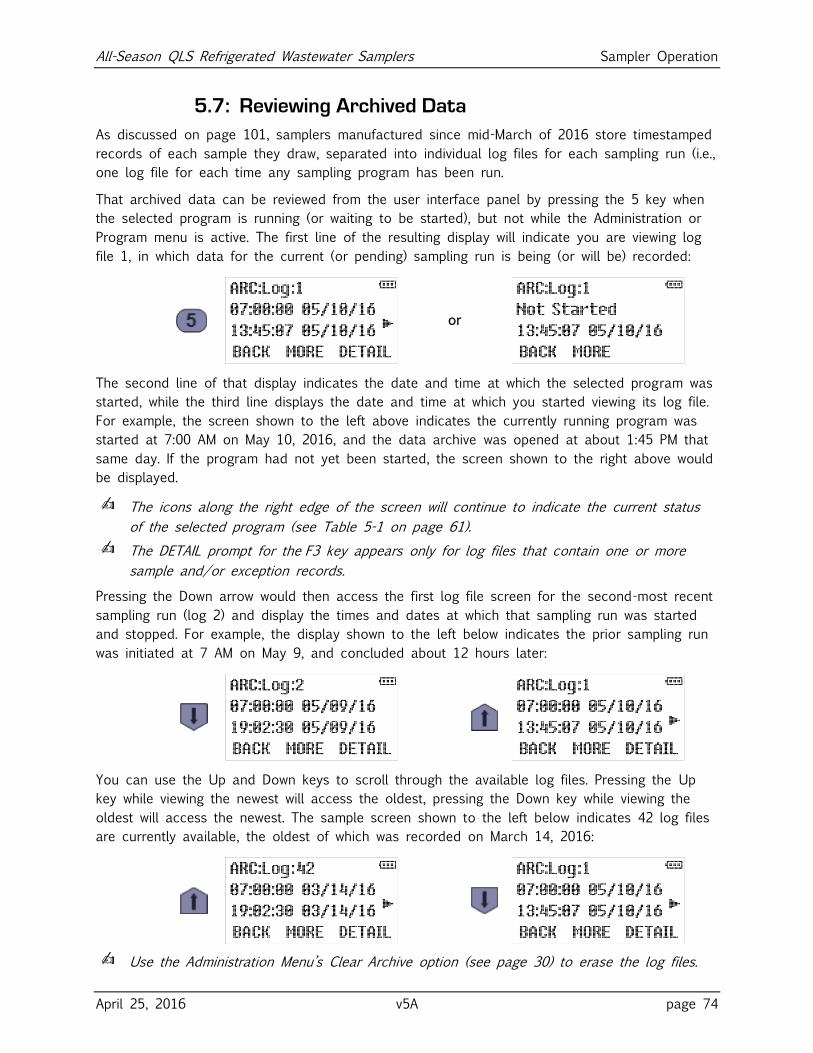
All-Season QLS Refrigerated Wastewater Samplers Sampler Operation
April 25, 2016 v5A page 74
5.7: Reviewing Archived Data
As discussed on page 101, samplers manufactured since mid-March of 2016 store timestamped
records of each sample they draw, separated into individual log files for each sampling run (i.e.,
one log file for each time any sampling program has been run.
That archived data can be reviewed from the user interface panel by pressing the 5 key when
the selected program is running (or waiting to be started), but not while the Administration or
Program menu is active. The first line of the resulting display will indicate you are viewing log
file 1, in which data for the current (or pending) sampling run is being (or will be) recorded:
or
The second line of that display indicates the date and time at which the selected program was
started, while the third line displays the date and time at which you started viewing its log file.
For example, the screen shown to the left above indicates the currently running program was
started at 7:00 AM on May 10, 2016, and the data archive was opened at about 1:45 PM that
same day. If the program had not yet been started, the screen shown to the right above would
be displayed.
✍ The icons along the right edge of the screen will continue to indicate the current status
of the selected program (see Table 5-1 on page 61).
✍ The DETAIL prompt for the F3 key appears only for log files that contain one or more
sample and/or exception records.
Pressing the Down arrow would then access the first log file screen for the second-most recent
sampling run (log 2) and display the times and dates at which that sampling run was started
and stopped. For example, the display shown to the left below indicates the prior sampling run
was initiated at 7 AM on May 9, and concluded about 12 hours later:
You can use the Up and Down keys to scroll through the available log files. Pressing the Up
key while viewing the newest will access the oldest, pressing the Down key while viewing the
oldest will access the newest. The sample screen shown to the left below indicates 42 log files
are currently available, the oldest of which was recorded on March 14, 2016:
✍ Use the Administration Menu’s Clear Archive option (see page 30) to erase the log files.
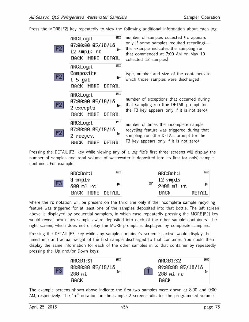
All-Season QLS Refrigerated Wastewater Samplers Sampler Operation
April 25, 2016 v5A page 75
Press the MORE [F2] key repeatedly to view the following additional information about each log:
number of samples collected (rc appears
only if some samples required recycling)—
this example indicates the sampling run
that commenced at 7:00 AM on May 10
collected 12 samples]
type, number and size of the containers to
which those samples were discharged
number of exceptions that occurred during
that sampling run (the DETAIL prompt for
the F3 key appears only if it is not zero)
number of times the incomplete sample
recycling feature was triggered during that
sampling run (the DETAIL prompt for the
F3 key appears only if it is not zero)
Pressing the DETAIL [F3] key while viewing any of a log file’s first three screens will display the
number of samples and total volume of wastewater it deposited into its first (or only) sample
container. For example:
or
where the rc notation will be present on the third line only if the incomplete sample recycling
feature was triggered for at least one of the samples deposited into that bottle. The left screen
above is displayed by sequential samplers, in which case repeatedly pressing the MORE [F2] key
would reveal how many samples were deposited into each of the other sample containers. The
right screen, which does not display the MORE prompt, is displayed by composite samplers.
Pressing the DETAIL [F3] key while any sample container’s screen is active would display the
timestamp and actual weight of the first sample discharged to that container. You could then
display the same information for each of the other samples in to that container by repeatedly
pressing the Up and/or Down keys:
The example screens shown above indicate the first two samples were drawn at 8:00 and 9:00
AM, respectively. The “rc” notation on the sample 2 screen indicates the programmed volume
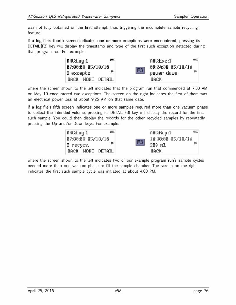
All-Season QLS Refrigerated Wastewater Samplers Sampler Operation
April 25, 2016 v5A page 76
was not fully obtained on the first attempt, thus triggering the incomplete sample recycling
feature.
If a log file’s fourth screen indicates one or more exceptions were encountered, pressing its
DETAIL [F3] key will display the timestamp and type of the first such exception detected during
that program run. For example:
where the screen shown to the left indicates that the program run that commenced at 7:00 AM
on May 10 encountered two exceptions. The screen on the right indicates the first of them was
an electrical power loss at about 9:25 AM on that same date.
If a log file’s fifth screen indicates one or more samples required more than one vacuum phase
to collect the intended volume, pressing its DETAIL [F3] key will display the record for the first
such sample. You could then display the records for the other recycled samples by repeatedly
pressing the Up and/or Down keys. For example:
where the screen shown to the left indicates two of our example program run’s sample cycles
needed more than one vacuum phase to fill the sample chamber. The screen on the right
indicates the first such sample cycle was initiated at about 4:00 PM.
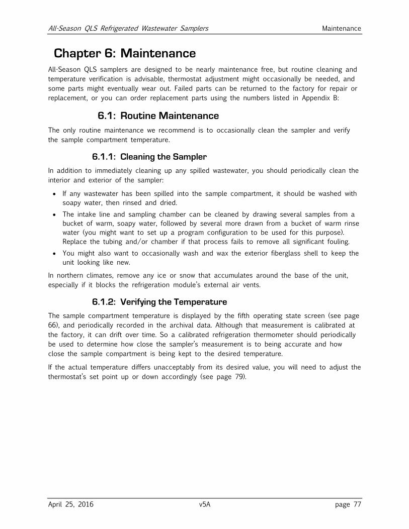
All-Season QLS Refrigerated Wastewater Samplers Maintenance
April 25, 2016 v5A page 77
Chapter 6: Maintenance All-Season QLS samplers are designed to be nearly maintenance free, but routine cleaning and
temperature verification is advisable, thermostat adjustment might occasionally be needed, and
some parts might eventually wear out. Failed parts can be returned to the factory for repair or
replacement, or you can order replacement parts using the numbers listed in Appendix B:
6.1: Routine Maintenance
The only routine maintenance we recommend is to occasionally clean the sampler and verify
the sample compartment temperature.
6.1.1: Cleaning the Sampler
In addition to immediately cleaning up any spilled wastewater, you should periodically clean the
interior and exterior of the sampler:
If any wastewater has been spilled into the sample compartment, it should be washed with
soapy water, then rinsed and dried.
The intake line and sampling chamber can be cleaned by drawing several samples from a
bucket of warm, soapy water, followed by several more drawn from a bucket of warm rinse
water (you might want to set up a program configuration to be used for this purpose).
Replace the tubing and/or chamber if that process fails to remove all significant fouling.
You might also want to occasionally wash and wax the exterior fiberglass shell to keep the
unit looking like new.
In northern climates, remove any ice or snow that accumulates around the base of the unit,
especially if it blocks the refrigeration module’s external air vents.
6.1.2: Verifying the Temperature
The sample compartment temperature is displayed by the fifth operating state screen (see page
66), and periodically recorded in the archival data. Although that measurement is calibrated at
the factory, it can drift over time. So a calibrated refrigeration thermometer should periodically
be used to determine how close the sampler’s measurement is to being accurate and how
close the sample compartment is being kept to the desired temperature.
If the actual temperature differs unacceptably from its desired value, you will need to adjust the
thermostat’s set point up or down accordingly (see page 79).
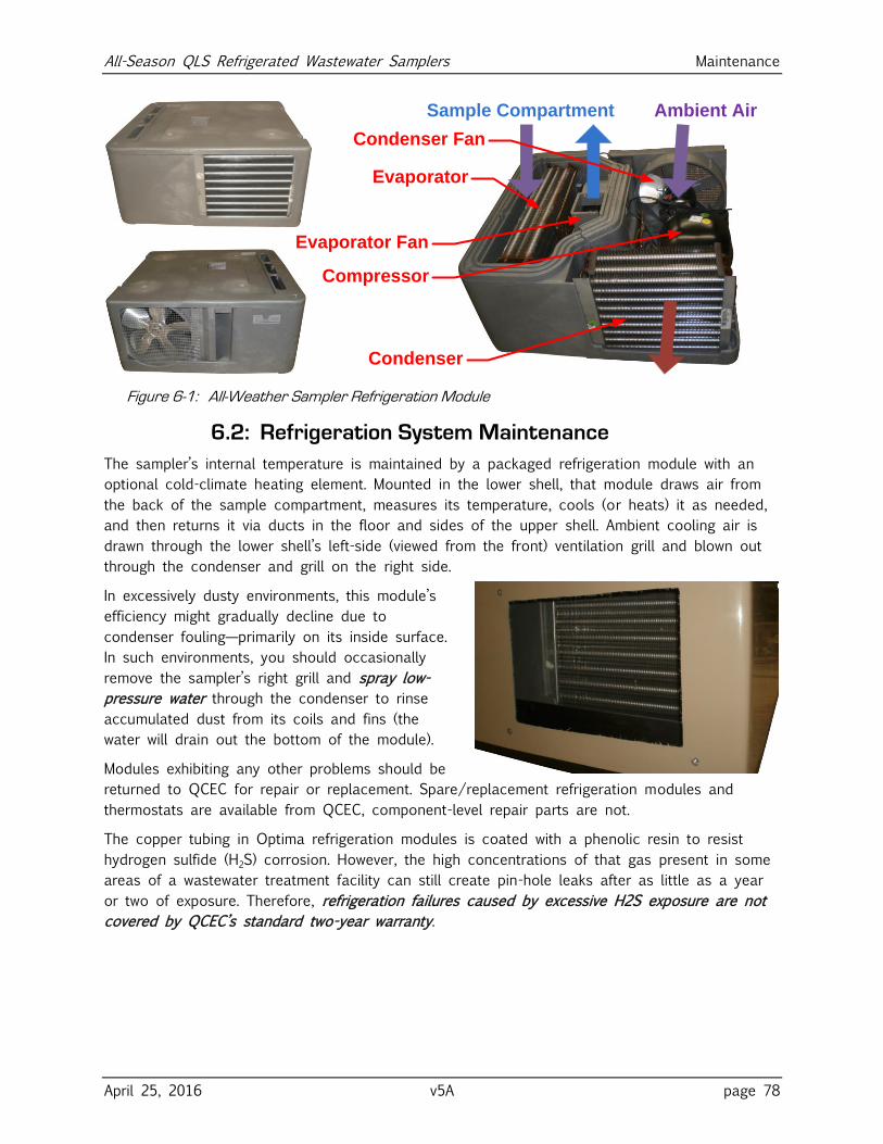
All-Season QLS Refrigerated Wastewater Samplers Maintenance
April 25, 2016 v5A page 78
Sample Compartment Ambient Air
Evaporator
Compressor
Condenser
Evaporator Fan
Condenser Fan
Figure 6-1: All-Weather Sampler Refrigeration Module
6.2: Refrigeration System Maintenance
The sampler’s internal temperature is maintained by a packaged refrigeration module with an
optional cold-climate heating element. Mounted in the lower shell, that module draws air from
the back of the sample compartment, measures its temperature, cools (or heats) it as needed,
and then returns it via ducts in the floor and sides of the upper shell. Ambient cooling air is
drawn through the lower shell’s left-side (viewed from the front) ventilation grill and blown out
through the condenser and grill on the right side.
In excessively dusty environments, this module’s
efficiency might gradually decline due to
condenser fouling—primarily on its inside surface.
In such environments, you should occasionally
remove the sampler’s right grill and spray low-
pressure water through the condenser to rinse
accumulated dust from its coils and fins (the
water will drain out the bottom of the module).
Modules exhibiting any other problems should be
returned to QCEC for repair or replacement. Spare/replacement refrigeration modules and
thermostats are available from QCEC, component-level repair parts are not.
The copper tubing in Optima refrigeration modules is coated with a phenolic resin to resist
hydrogen sulfide (H2S) corrosion. However, the high concentrations of that gas present in some
areas of a wastewater treatment facility can still create pin-hole leaks after as little as a year
or two of exposure. Therefore, refrigeration failures caused by excessive H2S exposure are not
covered by QCEC’s standard two-year warranty.
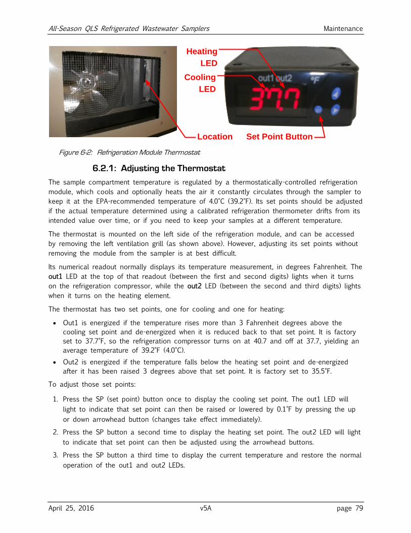
All-Season QLS Refrigerated Wastewater Samplers Maintenance
April 25, 2016 v5A page 79
Cooling
LED
Location Set Point Button
Heating
LED
Figure 6-2: Refrigeration Module Thermostat
6.2.1: Adjusting the Thermostat
The sample compartment temperature is regulated by a thermostatically-controlled refrigeration
module, which cools and optionally heats the air it constantly circulates through the sampler to
keep it at the EPA-recommended temperature of 4.0°C (39.2°F). Its set points should be adjusted
if the actual temperature determined using a calibrated refrigeration thermometer drifts from its
intended value over time, or if you need to keep your samples at a different temperature.
The thermostat is mounted on the left side of the refrigeration module, and can be accessed
by removing the left ventilation grill (as shown above). However, adjusting its set points without
removing the module from the sampler is at best difficult.
Its numerical readout normally displays its temperature measurement, in degrees Fahrenheit. The
out1 LED at the top of that readout (between the first and second digits) lights when it turns
on the refrigeration compressor, while the out2 LED (between the second and third digits) lights
when it turns on the heating element.
The thermostat has two set points, one for cooling and one for heating:
Out1 is energized if the temperature rises more than 3 Fahrenheit degrees above the
cooling set point and de-energized when it is reduced back to that set point. It is factory
set to 37.7°F, so the refrigeration compressor turns on at 40.7 and off at 37.7, yielding an
average temperature of 39.2°F (4.0°C).
Out2 is energized if the temperature falls below the heating set point and de-energized
after it has been raised 3 degrees above that set point. It is factory set to 35.5°F.
To adjust those set points:
1. Press the SP (set point) button once to display the cooling set point. The out1 LED will
light to indicate that set point can then be raised or lowered by 0.1°F by pressing the up
or down arrowhead button (changes take effect immediately).
2. Press the SP button a second time to display the heating set point. The out2 LED will light
to indicate that set point can then be adjusted using the arrowhead buttons.
3. Press the SP button a third time to display the current temperature and restore the normal
operation of the out1 and out2 LEDs.
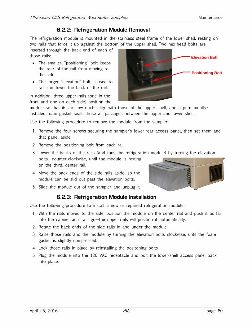
All-Season QLS Refrigerated Wastewater Samplers Maintenance
April 25, 2016 v5A page 80
6.2.2: Refrigeration Module Removal
The refrigeration module is mounted in the stainless steel frame of the lower shell, resting on
two rails that force it up against the bottom of the upper shell. Two hex-head bolts are
inserted through the back end of each of
those rails:
The smaller, “positioning” bolt keeps
the rear of the rail from moving to
the side.
The larger “elevation” bolt is used to
raise or lower the back of the rail.
In addition, three upper rails (one in the
front and one on each side) position the
module so that its air flow ducts align with those of the upper shell, and a permanently-
installed foam gasket seals those air passages between the upper and lower shell.
Use the following procedure to remove the module from the sampler:
1. Remove the four screws securing the sampler’s lower-rear access panel, then set them and
that panel aside.
2. Remove the positioning bolt from each rail.
3. Lower the backs of the rails (and thus the refrigeration module) by turning the elevation
bolts counter-clockwise, until the module is resting
on the third, center rail.
4. Move the back ends of the side rails aside, so the
module can be slid out past the elevation bolts.
5. Slide the module out of the sampler and unplug it.
6.2.3: Refrigeration Module Installation
Use the following procedure to install a new or repaired refrigeration module:
1. With the rails moved to the side, position the module on the center rail and push it as far
into the cabinet as it will go—the upper rails will position it automatically.
2. Rotate the back ends of the side rails in and under the module.
3. Raise those rails and the module by turning the elevation bolts clockwise, until the foam
gasket is slightly compressed.
4. Lock those rails in place by reinstalling the positoning bolts.
5. Plug the module into the 120 VAC receptacle and bolt the lower-shell access panel back
into place.
Positioning Bolt
Elevation Bolt
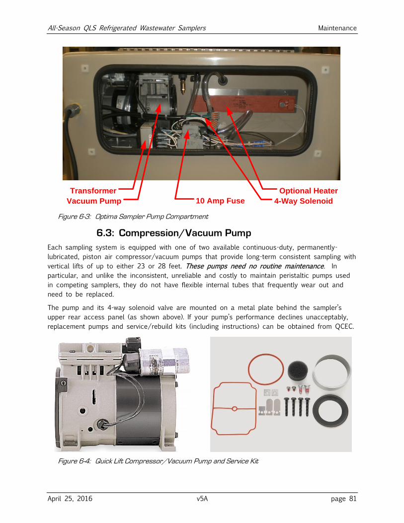
All-Season QLS Refrigerated Wastewater Samplers Maintenance
April 25, 2016 v5A page 81
Optional Heater
4-Way Solenoid
Transformer
Vacuum Pump 10 Amp Fuse
Figure 6-3: Optima Sampler Pump Compartment
6.3: Compression/Vacuum Pump
Each sampling system is equipped with one of two available continuous-duty, permanently-
lubricated, piston air compressor/vacuum pumps that provide long-term consistent sampling with
vertical lifts of up to either 23 or 28 feet. These pumps need no routine maintenance. In
particular, and unlike the inconsistent, unreliable and costly to maintain peristaltic pumps used
in competing samplers, they do not have flexible internal tubes that frequently wear out and
need to be replaced.
The pump and its 4-way solenoid valve are mounted on a metal plate behind the sampler’s
upper rear access panel (as shown above). If your pump’s performance declines unacceptably,
replacement pumps and service/rebuild kits (including instructions) can be obtained from QCEC.
Figure 6-4: Quick Lift Compressor/Vacuum Pump and Service Kit
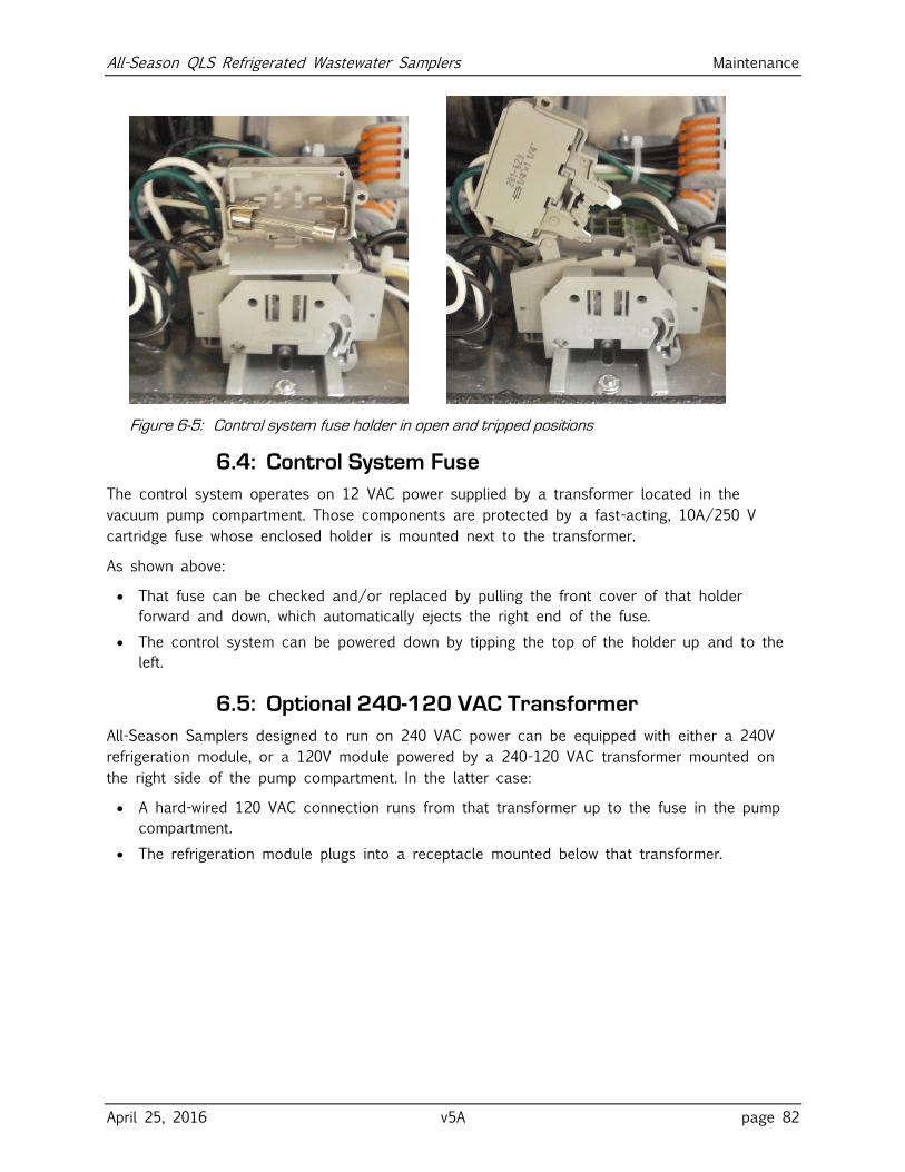
All-Season QLS Refrigerated Wastewater Samplers Maintenance
April 25, 2016 v5A page 82
Figure 6-5: Control system fuse holder in open and tripped positions
6.4: Control System Fuse
The control system operates on 12 VAC power supplied by a transformer located in the
vacuum pump compartment. Those components are protected by a fast-acting, 10A/250 V
cartridge fuse whose enclosed holder is mounted next to the transformer.
As shown above:
That fuse can be checked and/or replaced by pulling the front cover of that holder
forward and down, which automatically ejects the right end of the fuse.
The control system can be powered down by tipping the top of the holder up and to the
left.
6.5: Optional 240-120 VAC Transformer
All-Season Samplers designed to run on 240 VAC power can be equipped with either a 240V
refrigeration module, or a 120V module powered by a 240-120 VAC transformer mounted on
the right side of the pump compartment. In the latter case:
A hard-wired 120 VAC connection runs from that transformer up to the fuse in the pump
compartment.
The refrigeration module plugs into a receptacle mounted below that transformer.
All-Season QLS Refrigerated Wastewater Samplers Maintenance
April 25, 2016 v5A page 83
6.6: Troubleshooting Tips
Use the following suggestions to troubleshoot the listed problems.
1: User interface panel is dark:
a) Press any key to turn backlight on (it turns off after two minutes of inactivity).
b) If the screen is still dark but you can make out that it is displaying information, use
the Administration Menu to adjust the backlight (see page 29).
c) If the screen is uniformly black, make sure the sampler is powered up (you should be
able to hear the fan circulating air through the sample compartment).
d) Check the control system fuse (see page 82)
e) Reboot the controller by briefly tripping that fuse or unplugging the sampler.
f) If the controller is powered but its interface panel is black, the logic board is probably
defective—call QCEC for technical assistance.
2: One or more buttons never work:
a) The logic board is malfunctioning—call QCEC for technical assistance.
3: Readout never changes and cannot be scrolled:
a) Reboot the controller by briefly unplugging the sampler.
b) Controller hardware or software is faulty—call QCEC for technical assistance.
4: Readout indicates program will automatically start at midnight, 12/31/99
a) Stop the selected program and disable its Automatic Rerun parameter.
5: Readout indicates the load cell cannot be initialized:
a) Check the load cell controller’s plug-in connection
b) Call QCEC for technical assistance.
6: Readout indicates an indexing error
a) Make sure the bottle carousel is properly installed and is free to rotate.
b) Check the wiring for the sequential sampling turntable.
7: Readout indicates sampling failures—too little (if any) wastewater is collected:
a) Check the intake strainer and tube for obstructions and make sure the intake strainer
is fully submerged.
b) Make sure the intake line is properly connected to the sampler’s intake port. If a
compression fitting is used, the ferrule must be properly positioned and the nut
properly tightened.
c) Make sure the pinch valve is energizing and seals the discharge tube when it does.
d) Make sure the vacuum pump and solenoid are depressurizing the sample chamber.
e) Check for vacuum line leaks.
f) Adjust the velocity control valve for more vacuum.
All-Season QLS Refrigerated Wastewater Samplers Maintenance
April 25, 2016 v5A page 84
8: Samples are too large and/or wastewater is drawn into the pump:
a) Make sure line conditioning rinses are not drawing water into the sample chamber.
b) Make sure the sample chamber empties completely after each sample.
c) Adjust the velocity-limiting valve (see page 20).
d) Make sure the sample chamber and its discharge tube can rise and fall freely. The
discharge tube must not contact anything it passes through or past, such as the hole
(if any) in the lid of the sample container.
9: Purging does not clear the intake line:
a) Make sure the pinch valve is energizing and seals the discharge tube when it does.
b) Check the intake strainer and tube for obstructions.
c) Make sure the vacuum pump and solenoid are pressurizing the sample chamber.
10: Sampling continues despite full or over-flowing container(s):
a) Verify that the Bottle Limit option (see page 55) is set to “Program Stop”. If you
deliberately set it to “Program Continue”, the program will overfill the sample
containers if you fail to replace them in a timely fashion.
b) Make sure your Bottle Options (see page 47) settings match the installed sample
containers. If you specified a larger container size than you are actually using, and the
number of samples per bottle you specified will not fit in the installed container, the
program will overfill it.
c) Verify that samples of the intended size are being drawn (see item 8:).
11: Sample compartment temperature is too high or low:
a) Verify that the refrigeration module and its optional heating element are cycling.
b) Verify that the displayed temperatures are correct.
c) Check the temperature of the air being returned to the compartment to make sure the
refrigeration module is cooling.
d) Adjust the thermostat set points.
All-Season QLS Controller Capabilities
April 25, 2016 v5A page 85
Appendix A: Controller Capabilities This appendix describes the capabilities of the version 2.0 sample control system firmware, in
order to help you decide how best to adapt it to the needs of your sampling application.
A.1: Overview
The control system consists primarily of six sampling programs and a supervisory routine that
executes when the sampler is first powered up and whenever the selected program is stopped.
A.1.1: Supervisory Routine (Ready State)
When the sampler is powered up, the supervisory routine briefly displays the installed firmware
version number and revision letter (e.g., Version 2.0 Revision C). It then indicates the controller
is Ready to run. While it is operating in that state, the user interface panel can be used to:
start the selected program immediately,
start that program, but delay its execution to a specified future date and time-of-day, or
display its administration and configuration menus, in order to:
set the sampler’s configuration password and ID number, adjust its real-time clock and
display panel, and manage its archival data;
select and configure the control program; and
set up certain hardware and menu system features (QCEC personnel only).
Once the selected program has been started, the menu system functions are unavailable until it
stops (or is stopped)—at which time the controller returns to its supervisory/Ready state.
✍ The controller administration and program configuration functions are not available while
the sampling program is running.
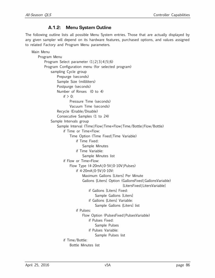
All-Season QLS Controller Capabilities
April 25, 2016 v5A page 86
A.1.2: Menu System Outline
The following outline lists all possible Menu System entries. Those that are actually displayed by
any given sampler will depend on its hardware features, purchased options, and values assigned
to related Factory and Program Menu parameters.
Main Menu
Program Menu
Program Select parameter (1|2|3|4|5|6)
Program Configuration menu (for selected program)
sampling Cycle group
Prepurge (seconds)
Sample Size (milliliters)
Postpurge (seconds)
Number of Rinses (0 to 4)
if > 0:
Pressure Time (seconds)
Vacuum Time (seconds)
Recycle (Enable/Disable)
Consecutive Samples (1 to 24)
Sample Intervals group
Sample Interval (Time|Flow|Time+Flow|Time/Bottle|Flow/Bottle)
if Time or Time+Flow:
Time Option (Time Fixed|Time Variable)
if Time Fixed:
Sample Minutes
if Time Variable:
Sample Minutes list
if Flow or Time+Flow:
Flow Type (4-20mA|0-5V|0-10V|Pulses)
if 4-20mA|0-5V|0-10V:
Maximum Gallons [Liters] Per Minute
Gallons {Liters] Option (GallonsFixed|GallonsVariable)
[LitersFixed|LitersVariable]
if Gallons [Liters] Fixed:
Sample Gallons [Liters]
if Gallons {Liters] Variable:
Sample Gallons {Liters] list
if Pulses:
Flow Option (PulsesFixed|PulsesVariable)
if Pulses Fixed:
Sample Pulses
if Pulses Variable:
Sample Pulses list
if Time/Bottle:
Bottle Minutes list
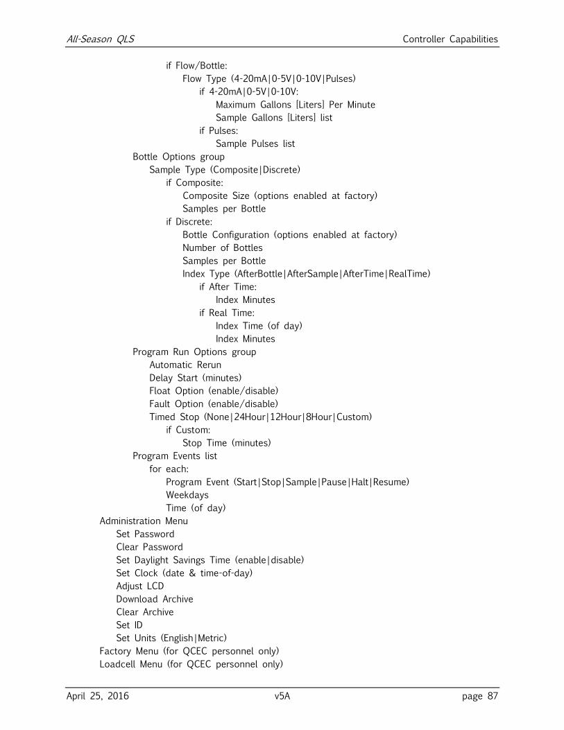
All-Season QLS Controller Capabilities
April 25, 2016 v5A page 87
if Flow/Bottle:
Flow Type (4-20mA|0-5V|0-10V|Pulses)
if 4-20mA|0-5V|0-10V:
Maximum Gallons [Liters] Per Minute
Sample Gallons [Liters] list
if Pulses:
Sample Pulses list
Bottle Options group
Sample Type (Composite|Discrete)
if Composite:
Composite Size (options enabled at factory)
Samples per Bottle
if Discrete:
Bottle Configuration (options enabled at factory)
Number of Bottles
Samples per Bottle
Index Type (AfterBottle|AfterSample|AfterTime|RealTime)
if After Time:
Index Minutes
if Real Time:
Index Time (of day)
Index Minutes
Program Run Options group
Automatic Rerun
Delay Start (minutes)
Float Option (enable/disable)
Fault Option (enable/disable)
Timed Stop (None|24Hour|12Hour|8Hour|Custom)
if Custom:
Stop Time (minutes)
Program Events list
for each:
Program Event (Start|Stop|Sample|Pause|Halt|Resume)
Weekdays
Time (of day)
Administration Menu
Set Password
Clear Password
Set Daylight Savings Time (enable|disable)
Set Clock (date & time-of-day)
Adjust LCD
Download Archive
Clear Archive
Set ID
Set Units (English|Metric)
Factory Menu (for QCEC personnel only)
Loadcell Menu (for QCEC personnel only)
All-Season QLS Controller Capabilities
April 25, 2016 v5A page 88
A.2: Inputs and Outputs
As shown on the Electrical Diagram appended to this manual, the sampling controller has the
following required and optional inputs and outputs:
run-status and alarm output relays (see below)
a turntable motor control output and two position sensor inputs (see below)
a sample-compartment temperature input (see page 89)
one analog and one discrete-pulse flow input (see page 89)
a float-switch input (see page 90)
the sample chamber’s load-cell controller (see page 90)
pump-motor, solenoid-valve and pinch-valve sampling outputs (see page 90)
A.2.1: Run-Status Output
The controller energizes the power board’s run-status relay (thus connecting pins 3 and 4 of
the optional field I/O connector) as each sampling cycle is initiated, and de-energizes it as that
cycle discharges the sample it collected.
A.2.2: Alarm Output
If the power board’s alarm relay is enabled (see page 53), the controller energizes it (thus
connecting pins 5 and 6 of the optional field I/O connector) when:
the sampling program is waiting to be reset after completing normally, being manually
stopped, or failing to determine the position of the sequential-sampling turntable;
sampling has been suspended because the float input circuit is open, as discussed below
(this will also be indicated by displaying a fault icon along the right edge of the screen);
the most recent sample cycle failed to determine the sampling chamber’s tare weight, or
failed to collect at least 60 percent of the specified sample volume; or
the storage compartment has been above its intended temperature for at least 30 minutes
(this will also be indicated by displaying a °C icon along the right edge of the screen).
A.2.3: Turntable I/O
The controller uses one discrete output and two discrete inputs to operate the optional
sequential-sampling turntable.
That output starts and stops the turntable’s motor by energizing and de-energizing the
power board’s table control relay.
Those inputs are wired to sensors that detect the passage of magnets (usually 24) that are
radially embedded in the turntable’s upper plate. The H sensor is positioned to detect the
turntable’s single home-position magnet, while the S sensor detects the others.
All three circuits are wired to a seven-pin CPC mounted in the roof of the sample compartment.
✍ Because the turntable uses a direct-current motor, its rotation can be reversed by
swapping the wires connected to pins 1 and 2 of the turntable CPC.
All-Season QLS Controller Capabilities
April 25, 2016 v5A page 89
A.2.4: Temperature Input
All-Season Samplers are equipped with resistive temperature devices (RTDs) that their controllers
use to measure their sample compartment temperatures. Each RTD is mounted to the return air
duct in the back of that compartment, and connected directly to the logic board’s temperature
input port.
A.2.5: Flow Input
The controller provides one analog and one discrete input that are meant for connecting flow
meter signals. All All-Season Samplers are equipped with four-pin circular plastic connectors
(CPC) that provide terminals for both of those inputs.
Connecting either type of signal allows you to configure flow interval counters (see page 94)
that will initiate samples as the total flow in the sampled stream passes specified volumes. Or,
the pulse input can be used to remotely trigger the collection of individual samples (see below):
To do that, you must set parameter(s) that specify the connected signal type (4-20 mA, 0-5
VDC, 0-10 VDC, or discrete pulse):
If an analog flow-rate signal is connected, you must also specify the flow rate (in gallons)
corresponding to its maximum value (20 mA, 5 VDC or 10 VDC) and the desired flow
intervals in gallons. The controller then integrates that signal to determine the accumulated
flow, and draws samples at the specified intervals.
✍ Multiple devices can be connected in series to a 4-to-20 mA transmitter, provided they do
not share a common ground and their summed resistances don’t exceed the transmitter’s
capacity. The internal resistance of our sampler’s current-loop input is 250 ohms.
The discrete signal type is intended to be used with a flow meter that integrates its own
flow rate measurement and pulses an output relay on and off at specific accumulated flow
intervals. If you connect such an input signal, you need only specify the number of pulses
corresponding to the flow intervals at which samples are to be drawn.
Assuming you really want your samples to be drawn at flow volume intervals, you can
calculate those counts by dividing the desired flow intervals (in volumetric units) by the
incremental flow (in the same units) that triggers each meter relay pulse.
For example, assume the meter pulses its output relay once for every 1000 gallons of
stream flow, and you want to sample that stream at 25,000 gallon intervals. You should
then set the interval duration to 25 pulses per sample (25000 gallons per sample divided
by 1000 gallons per pulse).
A.2.5.1: Remote Sample Initiation
Alternately, you can repurpose the pulse input to initiate a sample each time its circuit is
closed by a connected PLC or other external device, effectively allowing such a device to
remotely trigger the collection of individual samples.:
1. Select either the Flow or Time+Flow sampling interval option.
2. Set the Flow Type parameter to Pulses.
3. Set the Flow Option parameter to Pulses Fixed.
4. Set the Sample Pulses parameter to 1.
All-Season QLS Controller Capabilities
April 25, 2016 v5A page 90
A.2.6: Float Input
The controller provides one internally-powered discrete input that can be connected to an
external stream-level float switch. The controller can then be configured (see below) to draw
samples only while or after that input circuit has closed. Thus:
If a stream-level float switch is connected, it should close as the stream level rises above
an appropriate minimum level. The sampler could then be configured to draw samples only
when the stream depth was sufficient to cover the intake strainer (or above some other
appropriate threshold).
More generally, this is essentially a remote run-permissive input that could be connected to
any appropriate field device or PLC relay output.
A.2.6.1: Factory Menu Float Setting
If the Float Option (see page 54) is enabled and its input circuit is open when the control
program is started, the unit will not start drawing samples until the float switch circuit is closed.
If that circuit opens after sampling has begun, the program’s response will depend on its
Factory Menu FLT setting (which is set to your specifications before the unit is shipped):
If the FLT START/STOP setting is selected, the program will reset its sampling interval
counters and not restart them until the float circuit closes again (i.e., those counters will
restart from zero when the water level rises high enough to reclose the float switch).
If the FLT START setting is selected, the program will continue sampling without interruption
even if that circuit reopens.
If the FLT OFF setting is selected, the float input is disabled and the Program Menu’s FLOAT
INPUT parameter is hidden.
A.2.7: Load Cell Controller
Each sample cycle vacuums wastewater into the sample chamber until its load cell signals that
the programmed amount of liquid has been collected, as detailed in the QLS Sampling Cycle
section on page 92. That device has its own control box, mounted in the sample compartment,
which attaches to the controller’s SDI-12 communication port.
A.2.8: Sampling Outputs
Three electrically-actuated devices control the flow of air and wastewater into and out of the
sample chamber (as illustrated above). As shown on the appended Electrical Diagram, each of
those devices is controlled by a relay on the controller’s power board:
The Pump relay turns the compressor/vacuum pump motor on at the beginning of each
sampling cycle, and off after the collected sample has been discharged.
The Solenoid relay energizes and de-energizes the four-way solenoid valve that alternately
connects the sample chamber to that pump’s the vacuum or pressure port.
The Pinch relay energizes the pinch valve solenoid to seal off the chamber’s discharge tube
during all but the final (discharge) phase of the sampling cycle. That valve connects to it
via a 2-pin CPC in the roof of the sample compartment.
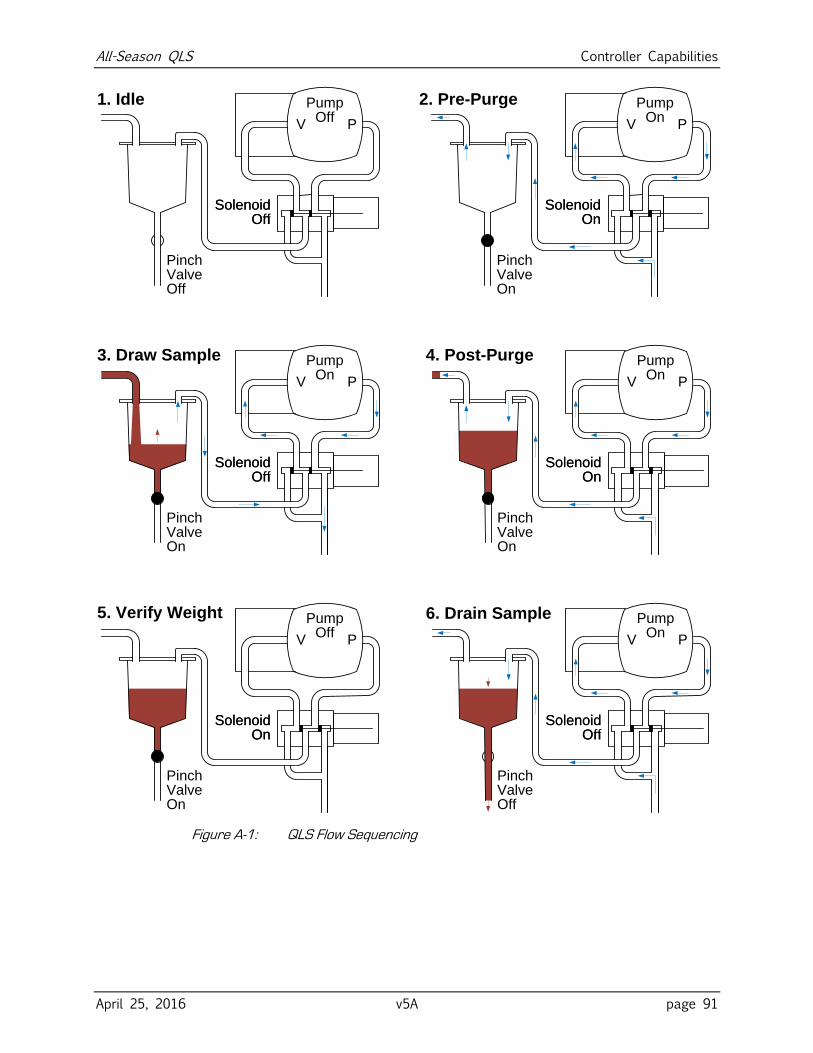
All-Season QLS Controller Capabilities
April 25, 2016 v5A page 91
SolenoidOn
V P
Pump Off
SolenoidOff
V P
Pump On
1. Idle
6. Drain Sample
4. Post-Purge
5. Verify Weight
3. Draw Sample
2. Pre-Purge
SolenoidOff
V P
Pump Off
SolenoidOn
V P
Pump On
SolenoidOff
V P
Pump On
SolenoidOn
V P
Pump On
SolenoidOn
PinchValveOff
SolenoidOn
PinchValveOn
SolenoidOn
PinchValveOn
SolenoidOn
PinchValveOn
SolenoidOn
PinchValveOn
SolenoidOn
PinchValveOff
Figure A-1: QLS Flow Sequencing
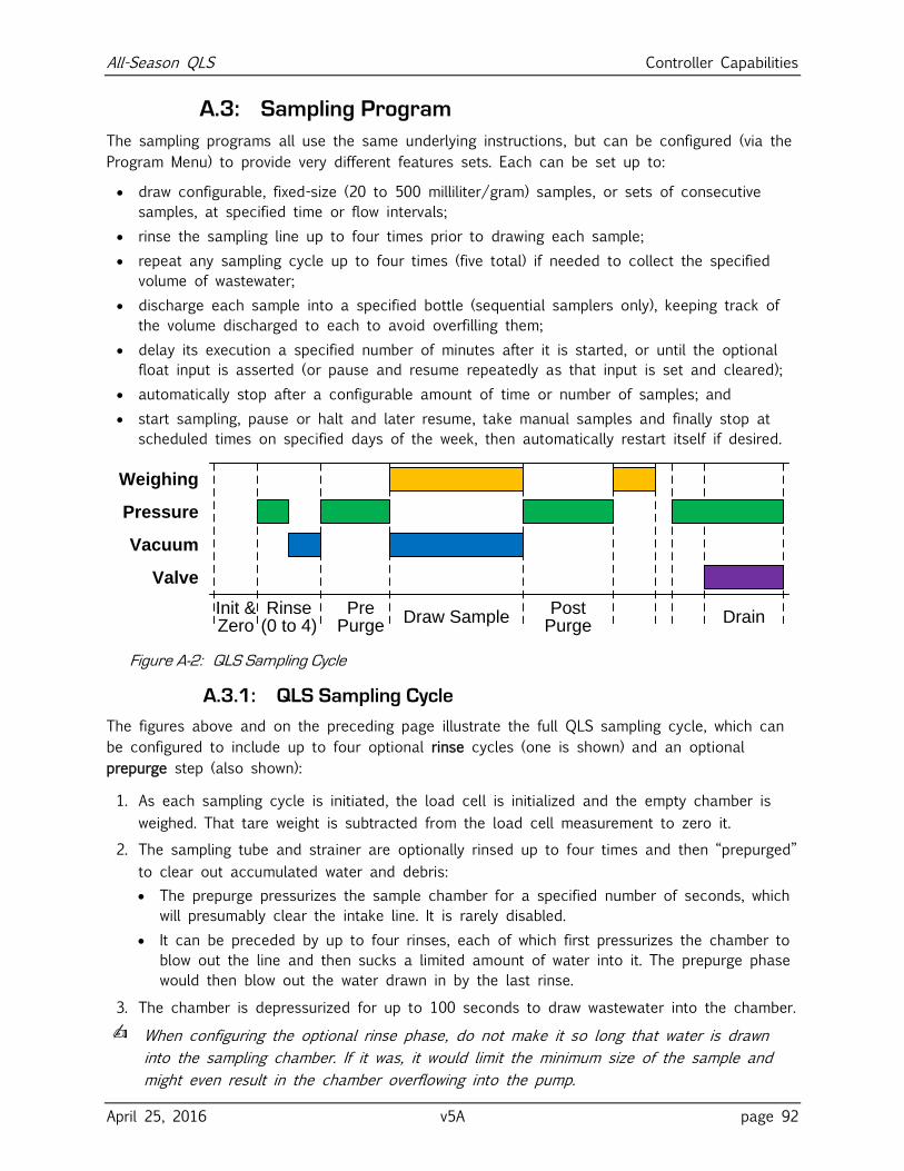
All-Season QLS Controller Capabilities
April 25, 2016 v5A page 92
A.3: Sampling Program
The sampling programs all use the same underlying instructions, but can be configured (via the
Program Menu) to provide very different features sets. Each can be set up to:
draw configurable, fixed-size (20 to 500 milliliter/gram) samples, or sets of consecutive
samples, at specified time or flow intervals;
rinse the sampling line up to four times prior to drawing each sample;
repeat any sampling cycle up to four times (five total) if needed to collect the specified
volume of wastewater;
discharge each sample into a specified bottle (sequential samplers only), keeping track of
the volume discharged to each to avoid overfilling them;
delay its execution a specified number of minutes after it is started, or until the optional
float input is asserted (or pause and resume repeatedly as that input is set and cleared);
automatically stop after a configurable amount of time or number of samples; and
start sampling, pause or halt and later resume, take manual samples and finally stop at
scheduled times on specified days of the week, then automatically restart itself if desired.
Draw SamplePost
PurgeDrain
PrePurge
Rinse(0 to 4)
Init &Zero
Pressure
Valve
Vacuum
Weighing
Figure A-2: QLS Sampling Cycle
A.3.1: QLS Sampling Cycle
The figures above and on the preceding page illustrate the full QLS sampling cycle, which can
be configured to include up to four optional rinse cycles (one is shown) and an optional
prepurge step (also shown):
1. As each sampling cycle is initiated, the load cell is initialized and the empty chamber is
weighed. That tare weight is subtracted from the load cell measurement to zero it.
2. The sampling tube and strainer are optionally rinsed up to four times and then “prepurged”
to clear out accumulated water and debris:
The prepurge pressurizes the sample chamber for a specified number of seconds, which
will presumably clear the intake line. It is rarely disabled.
It can be preceded by up to four rinses, each of which first pressurizes the chamber to
blow out the line and then sucks a limited amount of water into it. The prepurge phase
would then blow out the water drawn in by the last rinse.
3. The chamber is depressurized for up to 100 seconds to draw wastewater into the chamber.
✍ When configuring the optional rinse phase, do not make it so long that water is drawn
into the sampling chamber. If it was, it would limit the minimum size of the sample and
might even result in the chamber overflowing into the pump.
All-Season QLS Controller Capabilities
April 25, 2016 v5A page 93
4. The chamber is “postpurged” for a specified number of seconds to stop the flow and clear
at least the portion of the sampling tube that weighs on the load cell, so the sample can
be accurately weighed.
5. The weight of the sample is then determined.
6. If sample recycling (see page 93) is enabled and the sample is more than 40 percent
below its intended weight, the above steps will be repeated up to four times.
7. The final weight of the sample is recorded and the cycle is recalibrated (see page 93).
8. If the unit is equipped with a sequential-sampling carousel, it is rotated to position the
intended bottle beneath the discharge tube.
9. The sample is then discharged by blowing air into the chamber (which will create only a
slight positive pressure because the tube has been purged) and then opening the discharge
pinch valve.
10. If duplicate sampling has been set up (see page 98), this procedure immediately repeats
the specified number of times, discharging each consecutive sample into the next available
sequential-sampling bottle.
A.3.1.1: Automatic Calibration
In order to consistently draw samples of the specified size, the sampling cycle automatically
recalibrates itself using the following procedure:
1. The sample chamber’s tare weight is determined at the start of each sampling cycle.
2. Each sample is continuously weighed as it is drawn into the chamber.
3. When its net weight equals the configured sample size less a calibration factor calculated
from previous samples, the chamber is “postpurged” (i.e., briefly pressurized) to stop the
flow as quickly as possible. The weight of the additional wastewater that enters the
chamber while the flow is being reversed will ideally equal the calibration factor.
4. The sample is then reweighed and recorded. If it differs from the specified sample size, the
calibration factor is recalculated.
The previous sample data this process uses is cleared any time the sample size changes.
A.3.1.2: Sample Recycling
Enabling Recycling configures each sampling cycle to repeat its rinse, prepurge, sample,
postpurge and weigh phases up to four times before discharging the accumulated sample if:
the collected sample does not reach its target weight within the allotted 100 seconds, and
the final weight is less than 60 percent of the specified sample size.
If the sample was underweight because debris was sucked into and restricted the intake tube,
the repeated pre- and post-purging might clear the obstruction and allow the sample to reach
its intended weight/volume. If it was underweight because the sampler was sucking air due to
an insufficient sampled stream flow, that flow might increase during the recycling process.
In any event, if the final, discharged sample is underweight, a non-fatal fault is indicated and
the program keeps running. The fault is cleared the next time a full sample is collected.
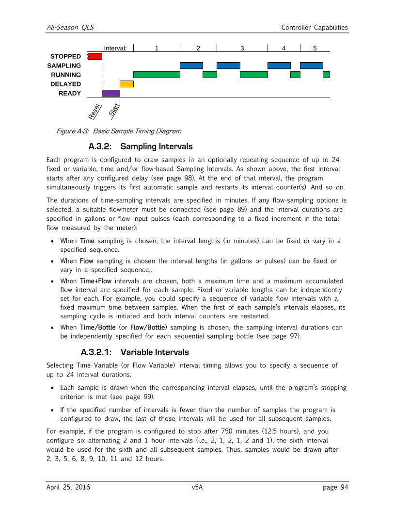
All-Season QLS Controller Capabilities
April 25, 2016 v5A page 94
RUNNING
DELAYED
STOPPED
READY
SAMPLING
1 2
Sta
rt
3
Rese
t
4Interval: 5
Figure A-3: Basic Sample Timing Diagram
A.3.2: Sampling Intervals
Each program is configured to draw samples in an optionally repeating sequence of up to 24
fixed or variable, time and/or flow-based Sampling Intervals. As shown above, the first interval
starts after any configured delay (see page 98). At the end of that interval, the program
simultaneously triggers its first automatic sample and restarts its interval counter(s). And so on.
The durations of time-sampling intervals are specified in minutes. If any flow-sampling options is
selected, a suitable flowmeter must be connected (see page 89) and the interval durations are
specified in gallons or flow input pulses (each corresponding to a fixed increment in the total
flow measured by the meter):
When Time sampling is chosen, the interval lengths (in minutes) can be fixed or vary in a
specified sequence.
When Flow sampling is chosen the interval lengths (in gallons or pulses) can be fixed or
vary in a specified sequence,.
When Time+Flow intervals are chosen, both a maximum time and a maximum accumulated
flow interval are specified for each sample. Fixed or variable lengths can be independently
set for each. For example, you could specify a sequence of variable flow intervals with a
fixed maximum time between samples. When the first of each sample’s intervals elapses, its
sampling cycle is initiated and both interval counters are restarted.
When Time/Bottle (or Flow/Bottle) sampling is chosen, the sampling interval durations can
be independently specified for each sequential-sampling bottle (see page 97).
A.3.2.1: Variable Intervals
Selecting Time Variable (or Flow Variable) interval timing allows you to specify a sequence of
up to 24 interval durations.
Each sample is drawn when the corresponding interval elapses, until the program’s stopping
criterion is met (see page 99).
If the specified number of intervals is fewer than the number of samples the program is
configured to draw, the last of those intervals will be used for all subsequent samples.
For example, if the program is configured to stop after 750 minutes (12.5 hours), and you
configure six alternating 2 and 1 hour intervals (i.e., 2, 1, 2, 1, 2 and 1), the sixth interval
would be used for the sixth and all subsequent samples. Thus, samples would be drawn after
2, 3, 5, 6, 8, 9, 10, 11 and 12 hours.
All-Season QLS Controller Capabilities
April 25, 2016 v5A page 95
A.3.3: Bottle Options
Each program must be “told” how many sample containers it is to use, how big they are, and
how many samples it is to put into each container. This is done by configuring the installed
Sampling Type and then setting the associated Bottle Options parameters:
If a single-container, composite-sampling system is installed, the Composite sampling type
must be selected—if you are even given a choice.
If a multiple-bottle, sequential-sampling system is installed, the Discrete sampling type must
be selected.
✍ Each sampler is usually sold with only a Composite or Sequential sample storage system
(see page 16). If so, each program is factory configured to use that Sample Type and the
Program Menu is set to keep you from changing it. That menu is also factory set to let
you select from only the container sizes or bottle carousels you have purchased.
✍ The maximum number of samples you can specify for each bottle is limited to 90 percent
of the selected bottle size divided by the Cycle group Sample Size parameter. Increasing
the sample size after the Samples per Bottle parameter has been set might automatically
reduce the value of the Sample Size parameter.
✍ At least one extra container or carousel and set of bottles is usually kept on hand to
allow sampling to continue while the filled bottles are readied for reuse.
A.3.3.1: Composite Sampling
If a single-container, composite-sampling system is installed, the Composite sampling type must
be selected. You then specify the size of that bottle and the Number of Samples to be
automatically collected and discharged to it:
The Composite Size setting specifies the size of the sample container.
The Samples per Bottle setting specifies how many samples will be discharged to that
container before the program automatically stops.
A.3.3.2: Sequential Sampling
If your sampler is equipped for sequential sampling, you must select the Discrete sampling type,
specify which bottle carousel is installed, and define the criteria for indexing (i.e. distributing)
samples among that carousel’s bottles:
The Bottle Configuration setting specifies the number and size of the bottles in the
carousel (for example, 24 1000 specifies a carousel housing 24 1000 milliliter bottles).
The Number of Bottles setting specifies how many of the available bottles will be used.
The Samples per Bottle setting specifies how many samples will be discharged to each
bottle before the program automatically stops.
The Index Type setting specifies when the next bottle will rotate into position.
Each program will always discharge its first sample into the bottle in the first carousel position.
If Number of Bottles is less than the number actually in the carousel, the difference dictates
how many will not receive any samples.
All-Season QLS Controller Capabilities
April 25, 2016 v5A page 96
A.3.3.2.1: After-Bottle Indexing
After-Bottle indexing rotates the carousel after each bottle has received the specified number of
Samples per Bottle. Thus, the carousel will rotate at most one full turn.
For example, assume a 24-bottle carousel is set for After Bottle indexing, Number of Bottles is
set to 20, and Samples per Bottle is set to 5. The program would then collect a total of 100
samples, discharging the first 5 to the position 1 bottle, the next five to the position 2 bottle,
and so on until samples 96 through 100 were discharged to the position 20 bottle, after which
the program would stop. Four bottles would remain empty.
A.3.3.2.2: After-Sample Indexing
After-Sample indexing rotates the carousel each time a sample is discharged, until each of the
specified Number of Bottles has received the specified Samples per Bottle. The carousel will
thus rotate Samples per Bottle full revolutions. Any manually-drawn samples would count toward
the Samples per Bottle limits of the bottles they were discharged to.
For example, assume a 24-bottle carousel is set for After Sample indexing, Number of Bottles is
set to 20, and Samples per Bottle is set to 5. The program would then collect a total of 100
samples, rotating the carousel 5 full turns. The first sample would be discharged to the bottle
in position 1, the second to the bottle in position 2, and so on until sample 20 was discharged
to the bottle in position 20. Bottle 1 would then be rotated into position to receive sample 21,
skipping the last four bottles. Sample 22 would be discharged to bottle 2, and so on until the
40th sample was discharged to bottle 20. This would repeat until sample 100 was discharged to
bottle 20, after which the program would stop.
A.3.3.2.3: After-Time Indexing
After-Time indexing type rotates the carousel in regular, timed steps whose duration is specified
by the Index Minutes parameter. The first indexing interval begins when the sampling interval
counters are initiated.
At the end of the first indexing interval, the second bottle is rotated into position and the
sampling interval counters are reset. The second bottle is then serviced for Index Minutes, after
which the third is rotated into position and the sampling intervals are again restarted. This
continues until the specified Number of Bottles have been serviced.
An additional run-time screen is provided which displays the duration of the indexing interval
and counts up to the next turntable rotation.
If any bottle receives the specified maximum Samples per Bottle before its indexing interval
elapses, no further samples will be drawn until the next bottle is rotated into position.
All-Season QLS Controller Capabilities
April 25, 2016 v5A page 97
A.3.3.2.4: Real-Time Indexing
Real-Time indexing is the same as After-Time indexing, except that it rotates the second bottle
into position at a specified Index Time (of day).
Ideally, the program would be started (or set to automatically start) Index Minutes prior to the
specified Index Time, so the first and each subsequent bottle would be used for Index Minutes.
For example, if Index Minutes is set to 1440 (24 hours) and Index Time is set to midnight on
January 2, sampling would ideally be started at midnight on January 1. The indexing counter
would then immediately start at 0 and count up to Index Minutes:
If the program is started more than Index Minutes before the specified Index Time, the
displayed indexing counter will not start until the time remaining until Index Time is equal
to Index Minutes.
If the program is started less than Index Minutes before Index Time, that counter starts
with an initial value greater than zero (essentially Index Time minus Index Minutes).
Real-Time indexing is the same as After-Time indexing, except that it rotates the second bottle
into position at a specified Index Time (of day). The displayed indexing interval counter does
not start until Index Minutes prior to the specified Index Time.
A.3.3.3: Per Bottle Sampling
If your sampler is equipped for sequential sampling, its programs can progress through a
sequence of sampling intervals as each bottle is rotated into position:
To set a different time sampling interval for each bottle, set the Sample Interval parameter
to Time/Bottle. Then define the interval for each bottle by setting the corresponding
element in the Bottle Minutes list.
To set a different flow sampling interval for each bottle, set the Sample Interval parameter
to Flow/Bottle. Then define the interval for each bottle by setting the corresponding
element in the Bottle Gallons or Bottle Pulses list.
You can set up to 24 such intervals (one for each bottle in a 24x500 or 24x1000 carousel),
but might not need to:
The Number of Bottles value you entered (see page 95) is the maximum number of
intervals you might need to set.
If you define a lesser number of intervals, the last one you do set will be used for all
subsequent bottles.
For example, if the program is configured to use six bottles, and you set a total of four
alternating 2 and 1 hour intervals (i.e., 2, 1, 2, 1), that fourth interval would be used for the
last three bottles:
Samples discharged to the first bottle would be drawn at 2-hour intervals.
Samples discharged to the second bottle would be drawn at 1-hour intervals.
Those discharged to the third bottle would again be drawn at 2-hour intervals.
All remaining samples would be drawn at 1-hour intervals (bottles 4, 5 and 6).
All-Season QLS Controller Capabilities
April 25, 2016 v5A page 98
A.3.3.4: Duplicate Sampling
If your sampler is equipped for sequential sampling, its programs can be configured to save
samples to multiple bottles at essentially the same time by:
assigning the Cycle group’s Consecutive Samples parameter a value greater than one, and
setting the Bottle Options group’s Index Type parameter to After Sample.
For example, assume a 24-bottle carousel is set for After Sample indexing, Number of Bottles
set to 24, Samples per Bottle set to 1 and Consecutive Samples is set to 3. Each time the
interval counter elapsed, three samples would be drawn as quickly as possible and discharged
to the next three empty bottles.
Assuming no manual samples were drawn, the first three samples would be drawn in quick
succession and discharged to bottles 1, 2 and 3. The second three would be discharged to
bottles 4, 5 and 6, and so on until the sixth set of three samples were drawn and discharged
to bottles 22, 23 and 24. The program would then stop.
If a manual sample was drawn after the second set of three automatic samples, it would be
discharged to bottle 7 and the third set of samples would be discharged to bottles 8, 9 and
10. Assuming no more manual samples, the fifth set of automatic samples would go into
bottles 20, 21 and 22. The sixth set could only discharge 2 samples—to bottles 23 and 24. The
program would then stop.
A.3.4: Delayed Starting
The selected sampling program can be started by pressing either the START [F1] or TIMED [F2]
key while the controller is in its Ready state (i.e., when the supervisory routine is running):
Pressing START [F1] starts the program immediately.
Pressing TIMED [F2] prompts you to specify the date and time at which the program will
appear to start. Until then, it will operate in a Timed state in which the sampling interval
counters do not run but you can initiate manual samples. An additional run-time screen will
display the date and time at which the program will “start”, along with the current time
and date. When that time comes, the program will proceed as if you had just pressed the
RUN [F1] key.
If one or more Program Start events (see page 100) have been configured, the program
will also enter its Timed state when the START [F1] key is pressed. It would then proceed
as if you had just pressed the RUN [F1] key when the first scheduled start time arrived.
In either case, the sampling interval counters might be further delayed:
If the program has been set to wait for a Float input (see page 90), it will not start its
interval counter(s) until that input is asserted. Until then, the program will display its
operating state as FLT START.
If a non-zero value (up to 9999 minutes) has been assigned to the Delay Start run Option
(see page 53), the first sampling interval will be further delayed by that many minutes (see
Figure A-3 on page 94). Until then, the program will display its operating state as DELAYED.
All-Season QLS Controller Capabilities
April 25, 2016 v5A page 99
A.3.5: Timed Stopping
Once a sampling program has started, it will continue running until it has drawn the number of
samples specified by its Bottle Options unless:
it is stopped by pressing the STOP [F3] key,
its Timed Stop Run Option (see page 54) has been set to stop it a specified number of
hours or minutes after the program was started, or
Stop Program events have been configured it to stop at configured times on specified days
of the week (see next section).
If either a Timed Stop or a Stop Program event has been configured, an additional run-time
screen will show the scheduled stop time and all such screens will display a timer icon.
All-Season QLS Controller Capabilities
April 25, 2016 v5A page 100
A.3.6: Scheduled Events
Each program can be set to automatically start its interval counters, pause or halt and then
resume, initiate manual samples, or stop itself at scheduled times on specified days of the
week. As discussed on page 56, those Program Events are defined by a variable-length list of
parameters, each of which has three associated values:
the type of event (see table on next page),
the days of the week on which the event will be executed, and
the time of day on those days at which the event will be initiated.
Events do not have to be defined in the order they will execute, and can only be added or
deleted from the end of the list.
Table A-1: Available Program Event Types
Start Program The parent program will start automatically if it is ready when the
scheduled time is reached on the next scheduled day.
Stop Program The parent program will stop automatically if it is running when the
scheduled time is reached on the next scheduled day. Unless the
Auto Rerun option is enabled (see page 52), the program will have
to be manually reset before it can be restarted.
Manual Sample A manual sample will be drawn if the program is running when the
scheduled time is reached on the next scheduled day. If a time or
flow interval elapses while the manual sample is being drawn, an
automatic sample will be drawn as soon as the manual sample
cycle has been completed.
Pause Program Sampling will be suspended if the program is running when the
scheduled time is reached on the next scheduled day, but the time
and flow interval counters will continue to run.
Sampling can be resumed by a Resume Program event, or from the
user interface panel. If one or more intervals elapse while the
program is paused, only the first such sample will be drawn when
the program is resumed.
Halt Program The interval time and flow counters will be paused if the program is
running when the scheduled time is reached on the next scheduled
day. Those counters can be resumed (with the accumulated values
they had at the time they were halted) by a Resume Program event,
or from the user interface panel.
Resume Program Interval sampling will resume if the program is paused or halted
when the scheduled time is reached on the next scheduled day.
End List Previous event is the last one on the list. Changing an event’s type
to End List deletes it and all high-numbered events.
All-Season QLS Controller Capabilities
April 25, 2016 v5A page 101
A.3.7: Data Archiving
Every sampler manufactured since mid-March of 2016 archives a timestamped record of:
each time one of its six sampling programs was started and stopped;
each sample it has collected, including its weight, which bottle it was deposited into, and
whether or not recycling was required to obtain the desired volume; and
all operational exceptions, including:
power loss and restoration,
bottle-full sampling suspensions,
sequential turntable indexing errors, and
sample compartment temperature deviations.
These sample and exception records are separated into multiple log files. Each time a sampling
program completes or is stopped, its log file is closed and a new one is opened. Exceptions
that occur between sampling runs are thus logged into the following run’s file. The controller
will keep up to 50 such files, after which the oldest file will be deleted each time a new one is
created. The newest file is accessed as log 1, the one recorded prior to log 1 is accessed as
log 2, and so on.
Currently, those log files can only be:
reviewed onscreen when the menu system is not in use (see page 74); and
deleted using the Administration Menu’s Clear Archive option (see page 30).
Future versions of the controller software will also provide ways to copy the log files to USB
memory devices, or download them to connected computers or SCADA systems.
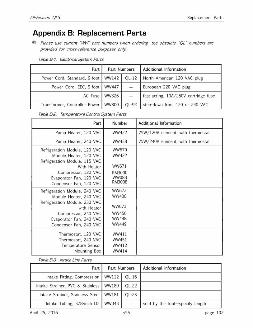
All-Season QLS Replacement Parts
April 25, 2016 v5A page 102
Appendix B: Replacement Parts ✍ Please use current “WW” part numbers when ordering—the obsolete “QL” numbers are
provided for cross-reference purposes only.
Table B-1: Electrical System Parts
Part Part Numbers Additional Information
Power Cord, Standard, 9-foot WW142 QL-12 North American 120 VAC plug
Power Cord, EEC, 9-foot WW447 ― European 220 VAC plug
AC Fuse WW326 ― fast-acting, 10A/250V cartridge fuse
Transformer, Controller Power WW300 QL-9R step-down from 120 or 240 VAC
Table B-2: Temperature Control System Parts
Part Number Additional Information
Pump Heater, 120 VAC WW422 75W/120V element, with thermostat
Pump Heater, 240 VAC WW438 75W/240V element, with thermostat
Refrigeration Module, 120 VAC
Module Heater, 120 VAC
Refrigeration Module, 115 VAC With Heater
Compressor, 120 VAC
Evaporator Fan, 120 VAC
Condenser Fan, 120 VAC
WW670 WW422
RM3000 WW083 RM3008
Refrigeration Module, 240 VAC
Module Heater, 240 VAC
Refrigeration Module, 230 VAC with Heater
Compressor, 240 VAC
Evaporator Fan, 240 VAC
Condenser Fan, 240 VAC
WW672 WW438
WW450
WW448
WW449
Thermostat, 120 VAC
Thermostat, 240 VAC
Temperature Sensor
Mounting Box
WW411
WW451
WW412
WW414
Table B-3: Intake Line Parts
Part Part Numbers Additional Information
Intake Fitting, Compression WW112 QL-16
Intake Strainer, PVC & Stainless WW189 QL-22
Intake Strainer, Stainless Steel WW181 QL-23
Intake Tubing, 3/8-inch I.D. WW043 ― sold by the foot—specify length
WW671
WW673
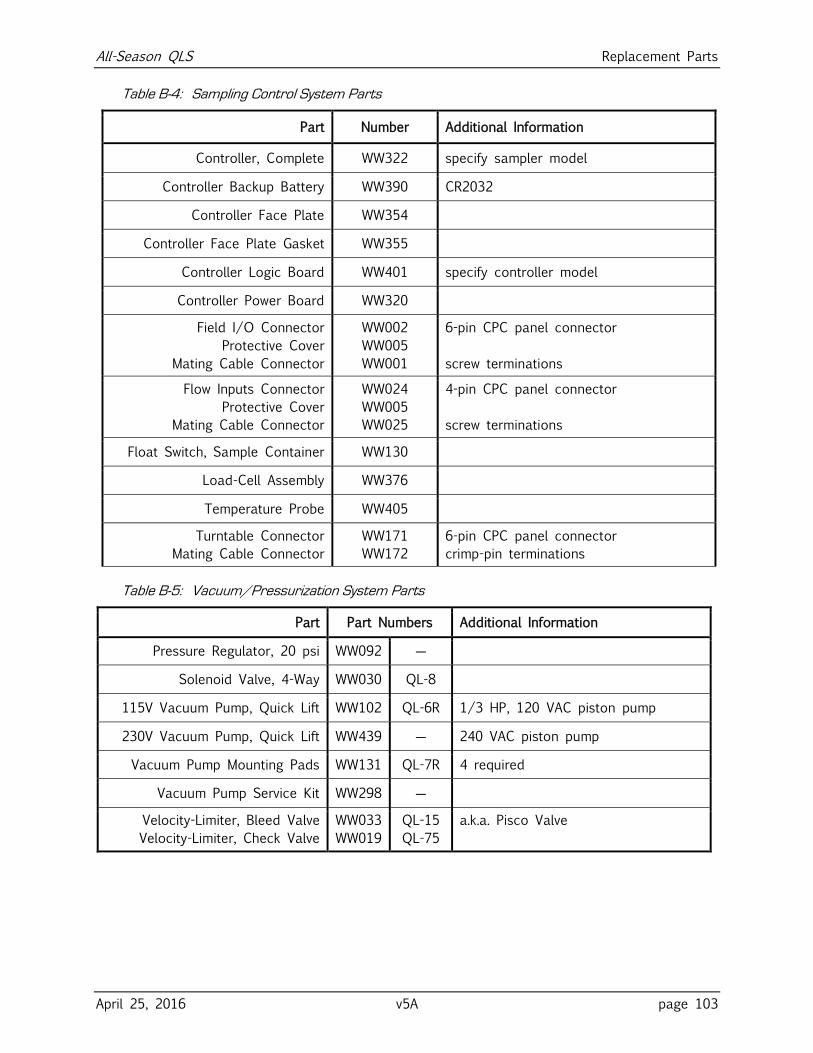
All-Season QLS Replacement Parts
April 25, 2016 v5A page 103
Table B-4: Sampling Control System Parts
Part Number Additional Information
Controller, Complete WW322 specify sampler model
Controller Backup Battery WW390 CR2032
Controller Face Plate WW354
Controller Face Plate Gasket WW355
Controller Logic Board WW401 specify controller model
Controller Power Board WW320
Field I/O Connector
Protective Cover
Mating Cable Connector
WW002
WW005
WW001
6-pin CPC panel connector
screw terminations
Flow Inputs Connector
Protective Cover
Mating Cable Connector
WW024
WW005
WW025
4-pin CPC panel connector
screw terminations
Float Switch, Sample Container WW130
Load-Cell Assembly WW376
Temperature Probe WW405
Turntable Connector
Mating Cable Connector
WW171
WW172
6-pin CPC panel connector
crimp-pin terminations
Table B-5: Vacuum/Pressurization System Parts
Part Part Numbers Additional Information
Pressure Regulator, 20 psi WW092 ―
Solenoid Valve, 4-Way WW030 QL-8
115V Vacuum Pump, Quick Lift WW102 QL-6R 1/3 HP, 120 VAC piston pump
230V Vacuum Pump, Quick Lift WW439 ― 240 VAC piston pump
Vacuum Pump Mounting Pads WW131 QL-7R 4 required
Vacuum Pump Service Kit WW298 ―
Velocity-Limiter, Bleed Valve
Velocity-Limiter, Check Valve
WW033
WW019
QL-15
QL-75
a.k.a. Pisco Valve
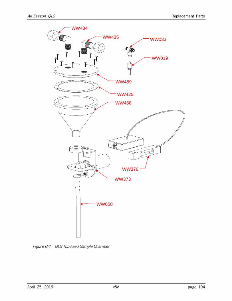
All-Season QLS Replacement Parts
April 25, 2016 v5A page 104
WW434
WW459
WW458
WW019
WW373
WW050
WW376
WW435
WW425
WW033
Figure B-1: QLS Top-Feed Sample Chamber
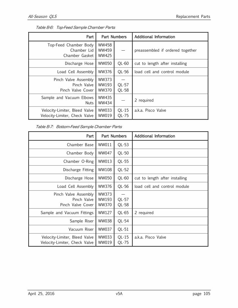
All-Season QLS Replacement Parts
April 25, 2016 v5A page 105
Table B-6: Top-Feed Sample Chamber Parts
Part Part Numbers Additional Information
Top-Feed Chamber Body
Chamber Lid
Chamber Gasket
WW458
WW459
WW425
— preassembled if ordered together
Discharge Hose WW050 QL-60 cut to length after installing
Load Cell Assembly WW376 QL-56 load cell and control module
Pinch Valve Assembly
Pinch Valve
Pinch Valve Cover
WW373
WW193
WW370
—
QL-57
QL-58
Sample and Vacuum Elbows
Nuts
WW435
WW434 — 2 required
Velocity-Limiter, Bleed Valve
Velocity-Limiter, Check Valve
WW033
WW019
QL-15
QL-75
a.k.a. Pisco Valve
Table B-7: Bottom-Feed Sample Chamber Parts
Part Part Numbers Additional Information
Chamber Base WW011 QL-53
Chamber Body WW047 QL-50
Chamber O-Ring WW013 QL-55
Discharge Fitting WW108 QL-52
Discharge Hose WW050 QL-60 cut to length after installing
Load Cell Assembly WW376 QL-56 load cell and control module
Pinch Valve Assembly
Pinch Valve
Pinch Valve Cover
WW373
WW193
WW370
—
QL-57
QL-58
Sample and Vacuum Fittings WW127 QL-65 2 required
Sample Riser WW038 QL-54
Vacuum Riser WW037 QL-51
Velocity-Limiter, Bleed Valve
Velocity-Limiter, Check Valve
WW033
WW019
QL-15
QL-75
a.k.a. Pisco Valve
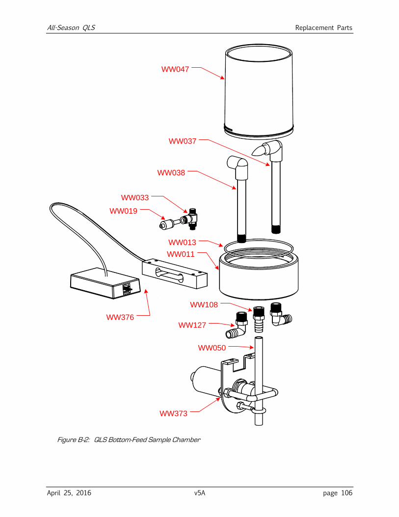
All-Season QLS Replacement Parts
April 25, 2016 v5A page 106
WW047
WW037
WW038
WW011
WW376
WW019
WW373
WW050
WW033
WW108
WW013
WW127
Figure B-2: QLS Bottom-Feed Sample Chamber
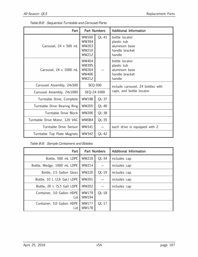
All-Season QLS Replacement Parts
April 25, 2016 v5A page 107
Table B-8: Sequential Turntable and Carousel Parts
Part Part Numbers Additional Information
Carousel, 24 x 500 mL
WW160
WW394
WW203
WW210
WW212
QL-41
bottle locator
plastic tub
aluminum base
handle bracket
handle
Carousel, 24 x 1000 mL
WW404
WW395
WW204
WW406
WW212
―
bottle locator
plastic tub
aluminum base
handle bracket
handle
Carousel Assembly, 24x500 SEQ-500 include carousel, 24 bottles with
caps, and bottle locator Carousel Assembly, 24x1000 SEQ-24-1000
Turntable Drive, Complete WW198 QL-37
Turntable Drive Bearing Ring WW205 QL-40
Turntable Drive Block WW206 QL-38
Turntable Drive Motor, 120 VAC WW084 QL-35
Turntable Drive Sensor WW341 ― each drive is equipped with 2
Turntable Top Plate Magnets WW342 QL-42
Table B-9: Sample Containers and Bottles
Part Part Numbers Additional Information
Bottle, 500 mL LDPE WW218 QL-34 includes cap
Bottle, Wedge, 1000 mL LDPE WW214 ― includes cap
Bottle, 2.5 Gallon Glass WW220 QL-19 includes cap
Bottle, 10 L (2.6 Gal.) LDPE WW201 ― includes cap
Bottle, 20 L (5.3 Gal) LDPE WW202 ― includes cap
Container, 3.0 Gallon HDPE
Lid
WW179
WW194
QL-18
Container, 5.0 Gallon HDPE
Lid
WW177
WW178
QL-17
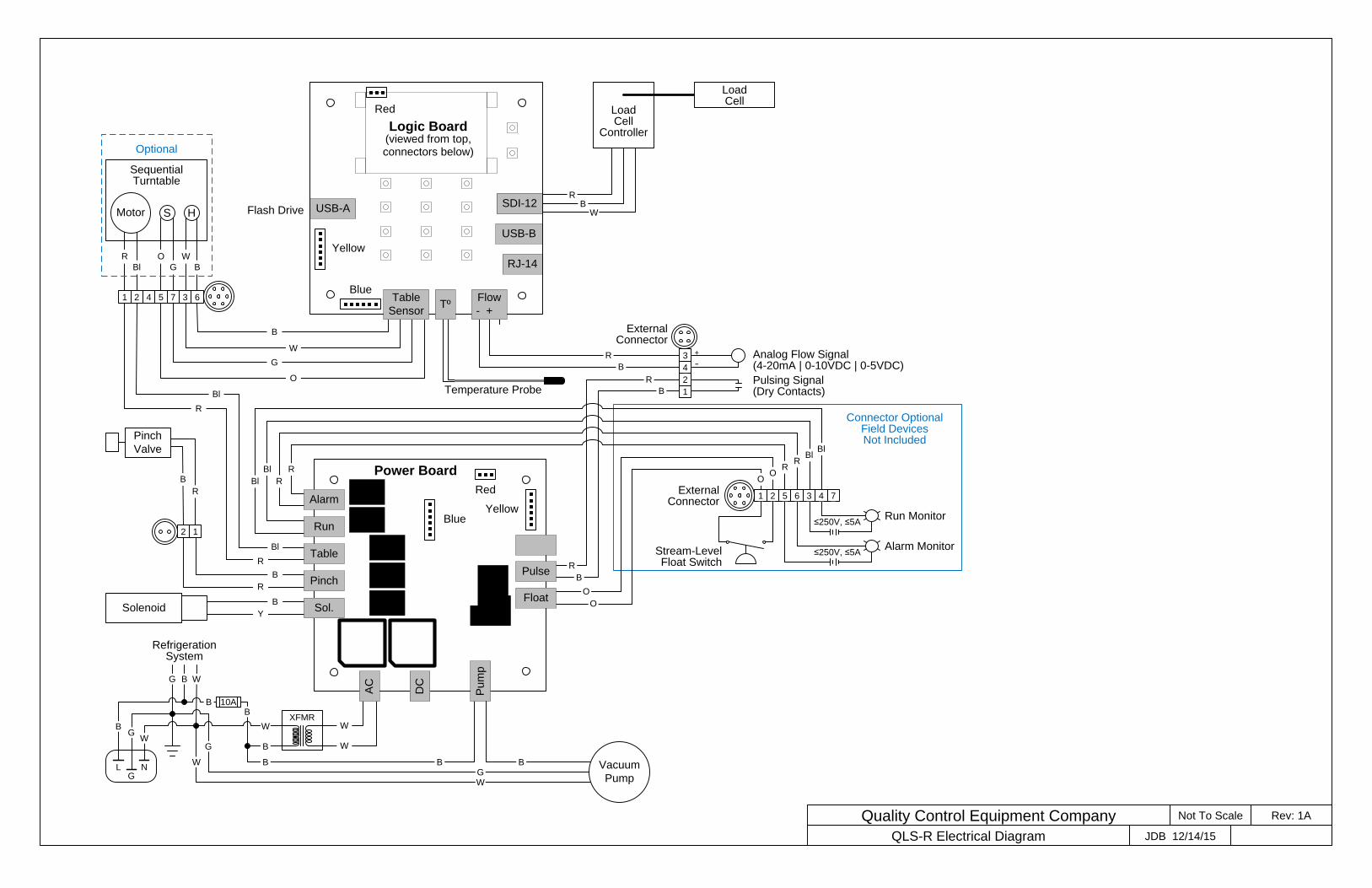
JDB 12/14/15
Rev: 1AQuality Control Equipment Company Not To Scale
QLS-R Electrical Diagram
Logic Board(viewed from top,connectors below)
USB-A SDI-12Flash Drive
USB-B
Red
Yellow
Blue
RJ-14
SDI-12
Pu
mp
DC
AC
Power Board
Red
YellowBlue
Temperature Probe
Tº
SolenoidB
Y
Pinch
Valve
B
R
Bl
R
Sol.
Pinch
Alarm
Run
Table
Sensor
G
O
B
W
2 1
6375421
Sequential Turntable
Motor S H
Bl
R
G
O
B
W
B
R
B
R
Bl
R
W
W
XFMR
Vacuum
PumpWG
Optional
BB
GL N
RefrigerationSystem
G WB
B
WG
B
W
B
B
10AB
W
G
B
R
B
R
Flow
- +
BR
W
LoadCell
Controller
R
Bl R
Bl
O
O
5 61 2 4 73External
Connector
Stream-Level Float Switch
Alarm Monitor
O
≤250V, ≤5ARun Monitor
≤250V, ≤5A
Connector OptionalField DevicesNot Included
R
BlR
Bl
O
External Connector
Analog Flow Signal(4-20mA | 0-10VDC | 0-5VDC)
Pulsing Signal(Dry Contacts)
2
1
3
4
Table
LoadCell
˗+
Float
Pulse


