QART##lR cn
64
7- QART##lR c n 1 -. - GROUP FOR AERONAUTICAL RESEARCH AND TECHNOLOGY IN EUROPE ORIGINAL: ENGLISH June 15,1995 GARTEUR Open Robust Flight Control Design Challenge Problem Formulation and Manual: the Research Civil Aircraft Model (RCAM) GARTEUR aims at stimulating and co-ordinating co-operation between Research Establishments and Industry in the areas of Aerodynamics, Flight Mechanics, Helicopters, Structures & Materials and Propulsion Technology
Transcript of QART##lR cn

7 - QART##lR c n 1 -. - GROUP FOR AERONAUTICAL RESEARCH AND TECHNOLOGY IN EUROPE
ORIGINAL: ENGLISH
June 15,1995
GARTEUR Open
Robust Flight Control Design Challenge Problem Formulation and Manual:
the Research Civil Aircraft Model (RCAM)
GARTEUR aims at stimulating and co-ordinating co-operation between Research Establishments and Industry in the areas of Aerodynamics, Flight Mechanics, Helicopters,
Structures & Materials and Propulsion Technology

GMRTEU!JR G R O U P FOR AERONAUTICAL RESEARCH A N D TECHNOLOGY IN EUROPE
ORIGINAL: ENGLISH
June 15,1995
GARTEUR Open
Robust Flight Control Design Challenge Problem Formulation and Manual:
the Research Civil Aircraft Model (RCAM)
This report has been prepared under auspices of the Responsables for Flight Mechanics, Systems and Integration of the Group for Aeronautical
Research and Technology in EURope (GARTEUR)
Group of Resp. : FM-GoR Action Group : FM(AG08) Report Resp. : P.F. Lambrechtsl rr-6+r Version : 1 Project Man. : J .C. Ter louw/s / r -a6-95 Completed : June 15,1995
Monitoring Resp. : J.T.M. van Doorn/ @ GARTEUR 1995

Version: 1 -iii- Date: June 15, 1995
GARTEURITP-088-3 QIRTEUI
Distribution list
FM-AGO8 principal persons
Ahmed S (GB) Ambrosino G (IT) Delgado I (ES)
Dormido S (ES)
Duranti P (IT) Helmersson A (SE)
Irving J (GB) Joos H D (DE)
Luckner R (DE)
Magni J F (FR) Muir E (GB) Post H (NL) Sheen P (GB)
S tiihl-Gunnarsson (SE) Terlouw J C (NL)
Vaart J C van der (NL)
Verde L (IT)
CCL UN INTA
UNED
ALN LiTH BAe (Warton)
DLR
DAA CERT-ONERA
DRA (Bedford)
FAC AVRO Intl
SMA NLR
DUT CIRA
1 COPY
1 COPY 1 COPY
1 COPY
1 COPY 1 COPY
1 COPY
1 COPY
1 COPY 1 COPY
1 COPY 1 COPY
1 COPY 1 COPY 3 copies
1 COPY
1 COPY
Members of the Flight Mechanics, Systems and Integration Group of Respon- sables
Brannstromm B (SE) FMV-F-EL 1 COPY
Doorn J T M van (NL) NLR 1 COPY
England P (GB) DRA (Bedford) 1 COPY
Rodloff R (DE) DLR 1 COPY Verbrugge R A (FR) ONERA-IMFL 1 COPY
Heads of National Delegates
Bocchet J (FR) DGA/DPSA 4 copies Earwicker M J (GB) DRA (Farnborough ) 4 copies
Dollinger W (DE) Bundesministerium fiir 4 copies
Forschung und Technologic
Houwelingen J van (NL) NLR 4 copies
Persson L B (SE) FFA 4 copies

Version: 1 Date: June 15, 1995 -zv- GARTEURITP-088-3 GRlFlTEUR
Members of the Executive Committee
Abbink F (NL) NLR 1 COPY Duc J M (FR) ONERA 1 COPY Gustafsson A (SE) FFA 1 COPY Haupt R (DE) DLRIPD-L 1 COPY Coleman G (GB) DRA (Farnborough) 1 COPY
Secretary GARTEUR
Sombroek L (NL) NLR
Others
Ackermann J (DE) Aranda J (ES) Bennani S (NL) Bernussou J (FR) Boer W P de (NL) Boumans L (NL) Ciniglio U (IT) Couwenberg M (NL) Cruz M de la (ES) Dam A A ten (NL) Dang Vu B (FR) Erkelens L (NL) Game G (GB) Geest P van der (NL) Gennuso D (IT) Griibel G (DE) Green M (GB) Goverde R (NL) Hulme K (GB) Huynh H T (FR) Hyde R (GB) Labarrkre M (FR) Lambrechts P (NL) Maciejowski J M (GB) Martinez A (ES) Menard P (FR) Moormann D (DE)
DLR UNED DUT LAAS-CNRS NLR NIVR CIRA NLR UNED NLR ONERA (Salon) NLR BAe (Filton) FAC ALN DLR AVRO htl NLR BAe (Warton) ONERA (Salon) CCL CERT-ONERA NLR UC INTA AS DLR
2 copies
1 COPY 1 COPY 2 copies
1 COPY 1 COPY 1 COPY 1 COPY 1 COPY 1 COPY 1 COPY 1 COPY 1 COPY 1 COPY 1 COPY 1 COPY 1 COPY 1 COPY 1 COPY 1 COPY 1 COPY 1 COPY 1 COPY 2 copies
1 COPY 1 COPY 1 COPY

Version: 1 -0- Date: June 15, 1995
GARTEURITP-088-3 Q@RPEUI
Morales M (ES)
Mulder A (NL) Rouwhorst W (NL)
Parra de la (ES)
Postlethwaite I (GB)
Scala S (IT) Schuring J (NL) Schuring-Coops M (NL)
Smith P (GB)
Spee J (NL) Tonon A (IT)
Valk P (NL) Weiden A van der (NL)
Weise K (DE)
INTA
FAC NLR
INTA
UL
CIRA NLR NLR
DRA (Bedford)
NLR ALN DUT
DUT DAA
1 COPY 1 COPY
1 COPY
1 COPY 2 copies
1 COPY
1 COPY
1 COPY
1 COPY
1 COPY
1 COPY 1 COPY
1 COPY
1 COPY

Version: 1 Date: June 15. 1995 -v2-
GARTEURITP-088-3 Q@NRIWk!JRd
Contents
List of figures . ix
List of tables x
List of symbols a n d abbreviations xi
1 Introduction 1
1.1 Objectives of GARTEUR Action Group FM-AGO8 . . . . . . . . . . 1
1.2 Objectives of subproject FM-AG08-3 . . . . . . . . . . . . . . . . . . 2
1.3 Contents of this document . . . . . . . . . . . . . . . . . . . . . . . . 3
2 Description of t h e RCAM Model 5
2.1 Block Diagram of the System . . . . . . . . . . . . . . . . . . . . . . 5
2.2 Nomenclature: Inputs. States. Outputs. Parameters . . . . . . . . . 6
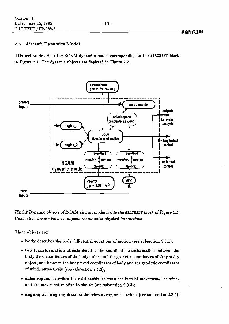
2.3 Aircraft Dynamics Model . . . . . . . . . . . . . . . . . . . . . . . . 10
2.3.1 Body equations of motion . . . . . . . . . . . . . . . . . . . . . . . . 11
2.3.1.1 Translational motion . . . . . . . . . . . . . . . . . . . . . . . . . . . 11
2.3.1.2 Rotational motion . . . . . . . . . . . . . . . . . . . . . . . . . . . . 12
2.3.2 Coordinate transformation (Body-Fixed Vehicle-Carried) . . . . . 12
2.3.3 Calculate Airspeed . . . . . . . . . . . . . . . . . . . . . . . . . . . . 13 2.3.4 Aerodynamics . . . . . . . . . . . . . . . . . . . . . . . . . . . . . . . 14
2.3.5 RCAM Engine Model . . . . . . . . . . . . . . . . . . . . . . . . . . 17
2.3.6 Atmosphere . . . . . . . . . . . . . . . . . . . . . . . . . . . . . . . . 18
2.3.7 Gravity Model . . . . . . . . . . . . . . . . . . . . . . . . . . . . . . 18
2.4 Sensor model . . . . . . . . . . . . . . . . . . . . . . . . . . . . . . . 18
2.5 Actuator models and engine dynamics . . . . . . . . . . . . . . . . . 19
2.6 W i d turbulence model . . . . . . . . . . . . . . . . . . . . . . . . . 19
3 Design problem formulation a n d evaluation criteria 2 1
3.1 Motivation design and evaluation criteria . . . . . . . . . . . . . . . 21
3.2 Design criteria . . . . . . . . . . . . . . . . . . . . . . . . . . . . . . 22
3.2.1 Introduction . . . . . . . . . . . . . . . . . . . . . . . . . . . . . . . . 22
3.2.2 Performance criteria . . . . . . . . . . . . . . . . . . . . . . . . . . . 22
3.2.3 Robustness criteria . . . . . . . . . . . . . . . . . . . . . . . . . . . . 25
3.2.4 Ride Quality Criteria . . . . . . . . . . . . . . . . . . . . . . . . . . . 25
3.2.5 Power consumption criteria . . . . . . . . . . . . . . . . . . . . . . . 25
3.2.6 Safety criteria . . . . . . . . . . . . . . . . . . . . . . . . . . . . . . . 25
3.3 Evaluation procedure: RCAM mission and scenario . . . . . . . . . . 26
3.4 Translation of design criteria into evaluation criteria . . . . . . . . . 28

Version: 1 -vii- Date: June 15. 1995
GARTEURITP-088-3 QB1TErYrR
3.4.1 Segment I . . . . . . . . . . . . . . . . . . . . . . . . . . . . . . . . . 28
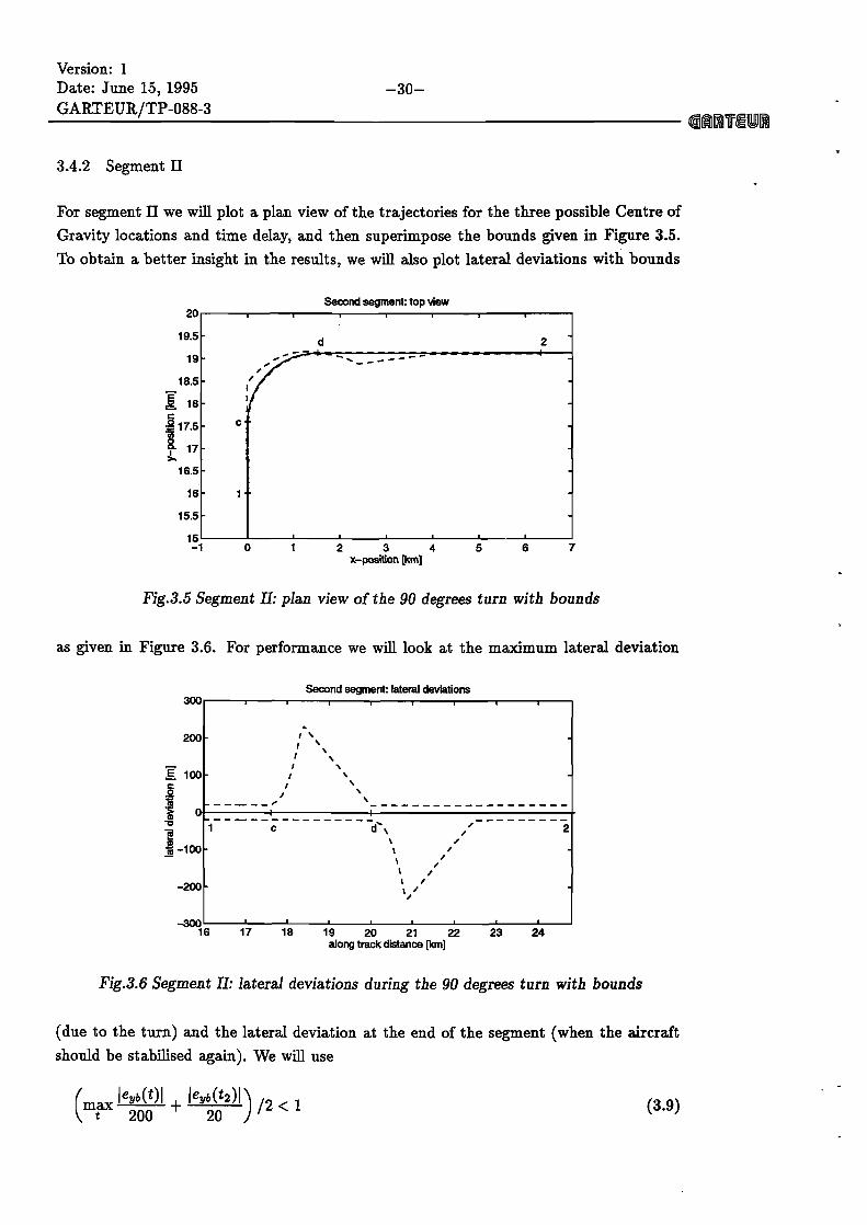
3.4.2 Segment 11 . . . . . . . . . . . . . . . . . . . . . . . . . . . . . . . . 30
3.4.3 Segment I11 . . . . . . . . . . . . . . . . . . . . . . . . . . . . . . . . . 31
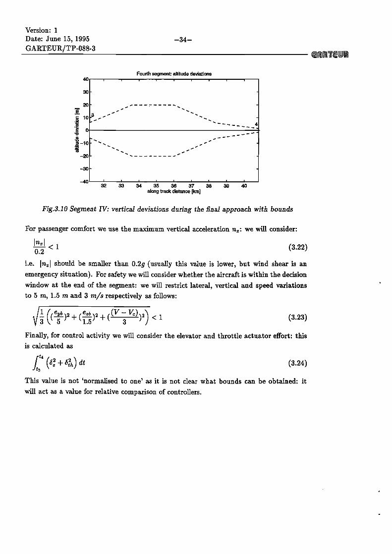
3.4.4 SegrnentIV . . . . . . . . . . . . . . . . . . . . . . . . . . . . . . . . 33
4 Design entry document layout
4.1 Introduction . . . . . . . . . . . . . . . . . . . . . . . . . . . . . . . . 4.2 Standard presentation format layout . . . . . . . . . . . . . . . . . . 4.3 Title page and preamble . . . . . . . . . . . . . . . . . . . . . . . . . 4.4 Summary and introduction contents . . . . . . . . . . . . . . . . . . 4.5 A tutorial review of the applied control design methodology . . . . . 4.6 The selection of the controller architecture for the RCAM problem . 4.7 The translation of the RCAM design criteria into method dependent
objectives . . . . . . . . . . . . . . . . . . . . . . . . . . . . . . . . . 4.8 The description of the design cycle . . . . . . . . . . . . . . . . . . . 4.9 Analysis of the resulting controller in terms of the applied methodology
4.10 Results of the automated evaluation procedure . . . . . . . . . . . . 4.1 1 Conclusions . . . . . . . . . . . . . . . . . . . . . . . . . . . . . . . . 4.12 References, Appendices, etc . . . . . . . . . . . . . . . . . . . . . . . . 4.13 Final remarks . . . . . . . . . . . . . . . . . . . . . . . . . . . . . . .
References 42
A The RCAM model and design environment software description 44
A.l RCAM model in MatlabISimulink . . . . . . . . . . . . . . . . . . . 44
A . 1.1 Installation . . . . . . . . . . . . . . . . . . . . . . . . . . . . . . . . 44
A . 1.1.1 From floppy disk . . . . . . . . . . . . . . . . . . . . . . . . . . . . . 44
A.1.1.2 From anonymous ftp . . . . . . . . . . . . . . . . . . . . . . . . . . . 45
A.1.1.3 Installed files . . . . . . . . . . . . . . . . . . . . . . . . . . . . . . . 46
A.1.2 Use . . . . . . . . . . . . . . . . . . . . . . . . . . . . . . . . . . . . . 46
A.2 Other RCAM model software . . . . . . . . . . . . . . . . . . . . . . 48
B The standard design challenge entry document layout 50
B.l Installation . . . . . . . . . . . . . . . . . . . . . . . . . . . . . . . . 50
B.l.l From floppy disk . . . . . . . . . . . . . . . . . . . . . . . . . . . . . 50
B.1.2 From anonymous ftp . . . . . . . . . . . . . . . . . . . . . . . . . . . 50
B.2 The first test . . . . . . . . . . . . . . . . . . . . . . . . . . . . . . . 51
B.3 The use of .STY files . . . . . . . . . . . . . . . . . . . . . . . . . . . 51
B.4 The example files . . . . . . . . . . . . . . . . . . . . . . . . . . . . . 51

Version: 1 Date: June 15, 1995 -viii- GARTEURf TP-088-3
QI ITEUI
The automated evaluation software 5 2 C.l Installation . . . . . . . . . . . . . . . . . . . . . . . . . . . . . . . . 52 C. l . l Fkom floppy disk . . . . . . . . . . . . . . . . . . . . . . . . . . . . . 52 C. 1.2 Fkom anonymous ftp . . . . . . . . . . . . . . . . . . . . . . . . . . . 52 C.1.3 Installedfiles . . . . . . . . . . . . . . . . . . . . . . . . . . . . . . . 53 C.2 The first test . . . . . . . . . . . . . . . . . . . . . . . . . . . . . . . 53 C.3 Use with your own controller . . . . . . . . . . . . . . . . . . . . . . 54

Version: 1 Date: June 15. 1995
List of figures
2.1 Simulink diagram of the system . . . . . . . . . . . . . . . . . . . . . . 2.2 Dynamic objects of RCAM aircraft model inside the AIRCRAFT block of
Figure 2.1. Connection arrows between objects characterise physical inter- . . . . . . . . . . . . . . . . . . . . . . . . . . . . . . . . . . . . . actions
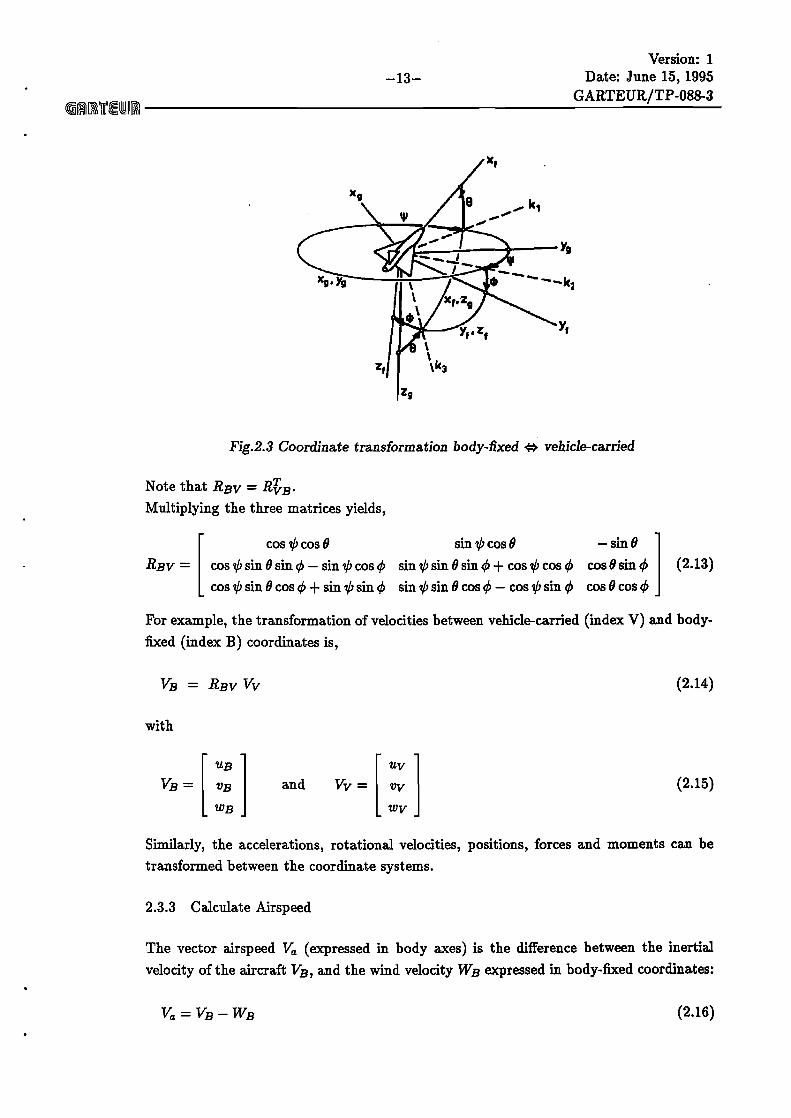
2.3 Coordinate transformation body-fixed e vehicle-carried . . . . . . . . . 2.4 Illustration of aerodynamic forces . . . . . . . . . . . . . . . . . . . . . . 2.5 Application points of thrusts . . . . . . . . . . . . . . . . . . . . . . . . . 2.6 Actuator models . . . . . . . . . . . . . . . . . . . . . . . . . . . . . . . 3.1 Maximum lateral deviation . . . . . . . . . . . . . . . . . . . . . . . . . 3.2 Maximum vertical deviation . . . . . . . . . . . . . . . . . . . . . . . . . 3.3 the landing approach for RCAM . . . . . . . . . . . . . . . . . . . . . . 3.4 Segment I: the effect of engine failure with bounds . . . . . . . . . . . . 3.5 Segment 11: plan view of the 90 degrees turn with bounds . . . . . . . . 3.6 Segment 11: lateral deviations during the 90 degrees turn with bounds . 3.7 Segment 111: side view of the -6 and -3 degrees glideslope captures with
bounds . . . . . . . . . . . . . . . . . . . . . . . . . . . . . . . . . . . . . 3.8 Segment 111: vertical deviations during the -6 and -3 degrees glideslope
captures with bounds . . . . . . . . . . . . . . . . . . . . . . . . . . . . 3.9 Segment IV: side view of the final approach with wind shear and bounds
3.10 Segment IV: vertical deviations during the final approach with bounds . -4.1 Simulink design model rcam-des . m . . . . . . . . . . . . . . . . . . . . . A.2 Sirnulink example controller model control . m . . . . . . . . . . . . . . .

Version: 1 Date: June 15. 1995 -2-
GARTEUR/TP-088-3 @@lITEUR
List of tables
2.1 Input definitions . . . . . . . . . . . . . . . . . . . . . . . . . . . . . . . . 6 2.2 States definitions . . . . . . . . . . . . . . . . . . . . . . . . . . . . . . . 7 2.3 Outputs definitions . . . . . . . . . . . . . . . . . . . . . . . . . . . . . . 8 2.4 Parameter definitions . . . . . . . . . . . . . . . . . . . . . . . . . . . . . 9 2.5 Parameter uncertainty deiinitions . . . . . . . . . . . . . . . . . . . . . . 9