QAM 12 QAM 12 EM QAM 8 EM - POLYTRON Broadband … · 3 1. Hazards and safety instructions Before...
28
QAM 12 QAM 12 EM QAM 8 EM Operating instructions MADE IN GERMANY 0901558 V4
Transcript of QAM 12 QAM 12 EM QAM 8 EM - POLYTRON Broadband … · 3 1. Hazards and safety instructions Before...

QAM 12
QAM 12 EM
QAM 8 EM
Operating instructions
MADE IN GERMANY 0901558 V4
2
Table of Contents Seite
1. Hazards and safety instructions 3
2. General Information 5
3. Device models 5
4. Description 5
5. Scope of delivery 5
6. Input circuit 5
7. Assembling 6
7.1 Grounding 6
8. Installation 6
8.1 QAM 8/12 EM 7
8.1.1 QAM 8/12 EM Default setting of the input 7
8.2 QAM 12 7
8.3 Input Level 8
8.4 Output Level 8
9. General programming 9
9.1 Software Installation 9
9.1.1 Installation of the driver 9
9.1.2 Installation of the programming software 10
9.2 Programming of the device parameters 10
9.2.1 Input parameters 11
9.2.2 Output parameters 13
9.3 Storage of the programs 15
9.3.1 Storage of the settings 15
9.3.2 Load settings 15
9.4 Diagnosis 16
9.5 LED-Analysis/Interpretation 16
9.6 Firmware update 17
9.6.1 CPU- (µ-Controller) 17
9.6.2 FPGA (QAM- Modulator) 17
10. Application examples 18
10.1 QAM 8/12 EM 18
10.2 QAM 12 19
11. Technical data 20
12. Statement of conformity 22
13. Default setting 23

3
1. Hazards and safety instructions
Before working with the basic unit QAM 8 EM/ QAM 12 EM / QAM12 please make sure you read the following safety rules carefully!
Power supply and power cord
The device must be operated only at a power supply with a voltage
of 230 V / 50 Hz.
Connection cable
Place the connection cable always trip proof !
Replace the power cord only with an original power cord.
Potential equalization / grounding
Proper grounding and installation of the device must be carried out according to EN 60728-11 / VDE 0855-1 regulations.
Operation without grounding or potential equalization of equipment is not allowed.
Humidity and placement location
The device must not be exposed to dripping or splashing water. If water condensation occurs, one must wait until the device is completely dry. The device must be installed on a vibration-free location.
Ambient temperature and heat effect
The maximum allowable ambient temperature is 45 ° C.
The ventilation holes of the device must NOT be covered under any circumstances. Too much heat or heat accumulation affect the life of the device and can be a source of danger.
To prevent heat buildup and to ensure good ventilation, the device must be mounted horizontally (eg. on a wall). The device must not be mounted above, on top, or near heat sources (e.g radiators, heating plants), where the device is exposed to heat radiation or oil vapors. The installation must be done only in rooms that ensure compliance with the permissible ambient temperature range, even under changing climatic conditions.
If the device exceeds the maximum operating temperature, it automatically switches to a reduced power consumption. The device is out of function during that time.
Once the temperature has reached again the allowable range, it automatically switches back on.
Warning:
When installed in rooms such as storage or attic one should pay particular attention on compliance with the ambient temperature. Because of the danger of fire due to overheating or lightning strike, it is recommendable to install the device on a noncombustible surface. Combustible surfaces are wood beams or bars, wood boards, plastic materials, etc.
Conditions to ensure electromagnetic compatibility (EMV - EMC ?)
All covers, screws and connectors must be securely mounted and tightened, contact springs must not be bent or oxidized.
4
Opening the case
ATTENTION
Device’s case opening and repairs must be performed only by authorized personnel. First to be done is to pull the network plug.
Replacing of fuses must be done only with fuses of same type, value and melting characteristics.
No maintenance work during storms
ATTENTION
This module contains ESD components! (ESD = Electrostatic Sensitive Device). An electrostatic discharge is an electrical current pulse, which can flow also through an electrically insulated material, when triggered by large voltage difference.
To ensure the reliability of ESD components, it is necessary to consider their most important handling rules:
Electrostatic sensitive components can be processed only on electrostatic protected area (EPA)!
Pay attention permanently to potential equalization (equipotential bonding)!
Use wrist straps, approved footwear for personnel grounding!
Avoid electrostatically chargeable materials such as normal PE, PVC, polystyrene!
Avoid electrostatic fields >100 V/cm !
Use only labeled and defined packing and transportation materials!
Damage caused by faulty connections and / or improper handling are excluded from any liability.
Waste disposal
Electronic equipment is not household waste but should be properly disposed on electrical and electronic equipment waste - in accordance with Directive 2002/96/EC OF THE EUROPEAN PARLIAMENT AND COUNCIL.
Please take this device at the end of its use for proper disposal at the designated public collection points.
WEEE-Reg.-Nr. DE 51035844
5
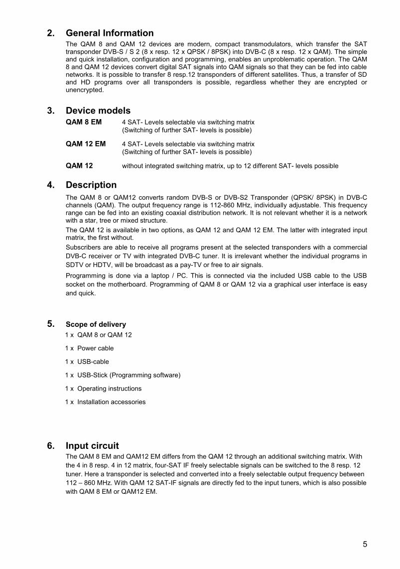
2. General Information The QAM 8 and QAM 12 devices are modern, compact transmodulators, which transfer the SAT transponder DVB-S / S 2 (8 x resp. 12 x QPSK / 8PSK) into DVB-C (8 x resp. 12 x QAM). The simple and quick installation, configuration and programming, enables an unproblematic operation. The QAM 8 and QAM 12 devices convert digital SAT signals into QAM signals so that they can be fed into cable networks. It is possible to transfer 8 resp.12 transponders of different satellites. Thus, a transfer of SD and HD programs over all transponders is possible, regardless whether they are encrypted or unencrypted.
3. Device models QAM 8 EM 4 SAT- Levels selectable via switching matrix
(Switching of further SAT- levels is possible)
QAM 12 EM 4 SAT- Levels selectable via switching matrix
(Switching of further SAT- levels is possible)
QAM 12 without integrated switching matrix, up to 12 different SAT- levels possible
4. Description
The QAM 8 or QAM12 converts random DVB-S or DVB-S2 Transponder (QPSK/ 8PSK) in DVB-C channels (QAM). The output frequency range is 112-860 MHz, individually adjustable. This frequency range can be fed into an existing coaxial distribution network. It is not relevant whether it is a network with a star, tree or mixed structure.
The QAM 12 is available in two options, as QAM 12 and QAM 12 EM. The latter with integrated input matrix, the first without.
Subscribers are able to receive all programs present at the selected transponders with a commercial
DVB-C receiver or TV with integrated DVB-C tuner. It is irrelevant whether the individual programs in
SDTV or HDTV, will be broadcast as a pay-TV or free to air signals.
Programming is done via a laptop / PC. This is connected via the included USB cable to the USB
socket on the motherboard. Programming of QAM 8 or QAM 12 via a graphical user interface is easy
and quick.
5. Scope of delivery 1 x QAM 8 or QAM 12
1 x Power cable
1 x USB-cable
1 x USB-Stick (Programming software)
1 x Operating instructions
1 x Installation accessories
6. Input circuit The QAM 8 EM and QAM12 EM differs from the QAM 12 through an additional switching matrix. With
the 4 in 8 resp. 4 in 12 matrix, four-SAT IF freely selectable signals can be switched to the 8 resp. 12
tuner. Here a transponder is selected and converted into a freely selectable output frequency between
112 – 860 MHz. With QAM 12 SAT-IF signals are directly fed to the input tuners, which is also possible
with QAM 8 EM or QAM12 EM.
6
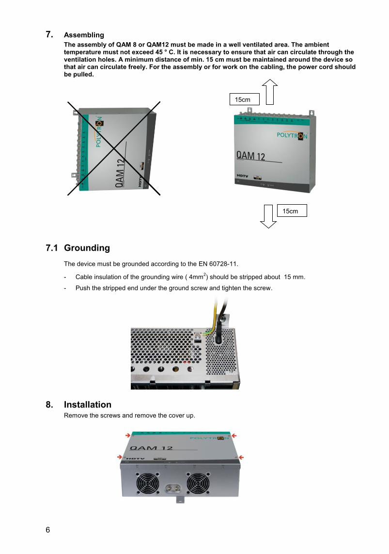
7. Assembling The assembly of QAM 8 or QAM12 must be made in a well ventilated area. The ambient temperature must not exceed 45 ° C. It is necessary to ensure that air can circulate through the ventilation holes. A minimum distance of min. 15 cm must be maintained around the device so that air can circulate freely. For the assembly or for work on the cabling, the power cord should be pulled.
7.1 Grounding
The device must be grounded according to the EN 60728-11.
- Cable insulation of the grounding wire ( 4mm2) should be stripped about 15 mm.
- Push the stripped end under the ground screw and tighten the screw.
8. Installation Remove the screws and remove the cover up.
15cm
15cm
7
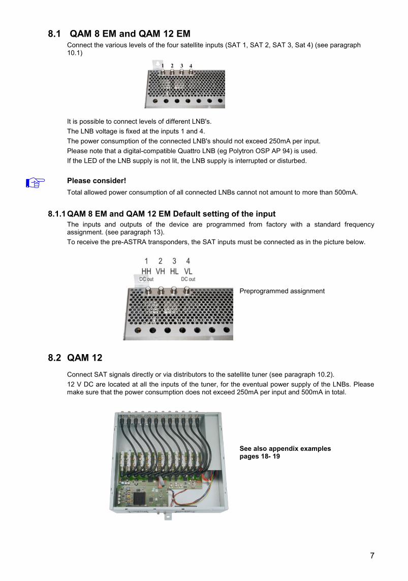
8.1 QAM 8 EM and QAM 12 EM Connect the various levels of the four satellite inputs (SAT 1, SAT 2, SAT 3, Sat 4) (see paragraph 10.1)
It is possible to connect levels of different LNB's.
The LNB voltage is fixed at the inputs 1 and 4.
The power consumption of the connected LNB's should not exceed 250mA per input.
Please note that a digital-compatible Quattro LNB (eg Polytron OSP AP 94) is used.
If the LED of the LNB supply is not lit, the LNB supply is interrupted or disturbed.
Please consider!
Total allowed power consumption of all connected LNBs cannot not amount to more than 500mA.
8.1.1 QAM 8 EM and QAM 12 EM Default setting of the input
The inputs and outputs of the device are programmed from factory with a standard frequency assignment. (see paragraph 13).
To receive the pre-ASTRA transponders, the SAT inputs must be connected as in the picture below.
Preprogrammed assignment
8.2 QAM 12
Connect SAT signals directly or via distributors to the satellite tuner (see paragraph 10.2).
12 V DC are located at all the inputs of the tuner, for the eventual power supply of the LNBs. Please make sure that the power consumption does not exceed 250mA per input and 500mA in total.
See also appendix examples pages 18- 19
8
8.3 Input level To ensure a good reception, make sure that the level at the inputs is between 50 and 80 dBµV.
When receiving digital signals, it is more beneficial to have a lower level rather than a too high level.
At too high input levels an attenuator should be used.
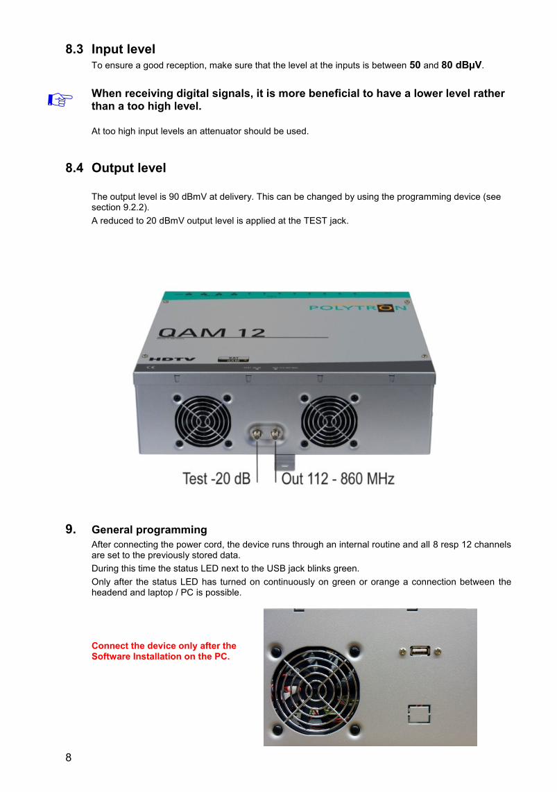
8.4 Output level
The output level is 90 dBmV at delivery. This can be changed by using the programming device (see section 9.2.2).
A reduced to 20 dBmV output level is applied at the TEST jack.
9. General programming
After connecting the power cord, the device runs through an internal routine and all 8 resp 12 channels are set to the previously stored data.
During this time the status LED next to the USB jack blinks green.
Only after the status LED has turned on continuously on green or orange a connection between the headend and laptop / PC is possible.
Connect the device only after the Software Installation on the PC.
9
If the USB socket should not be available from outside, so you can disconnect the connection cable.
The cable must be pushed into the white clamp (picture).
The USB plug may not touch the PCB or power supply.
Now the programming is only possible inside the housing..
9.1 Software Installation
Download the software package from the homepage www.polytron.de (satc12_Vxxx.zip) and
unzip it in a desired path (z. B. C:\ QAM12).
The software can be loaded also from the supplied USB- Stick.
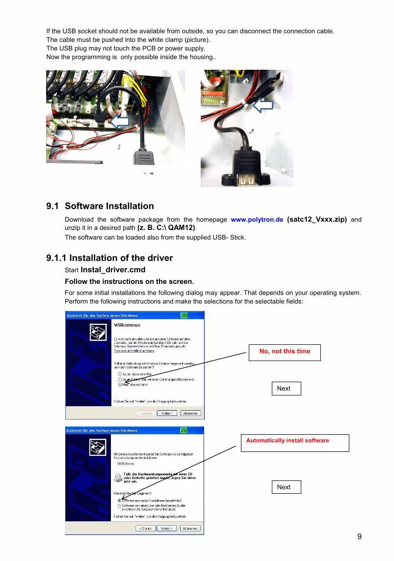
9.1.1 Installation of the driver
Start Instal_driver.cmd
Follow the instructions on the screen.
For some initial installations the following dialog may appear. That depends on your operating system.
Perform the following instructions and make the selections for the selectable fields:
No, not this time
Next
Automatically install software
Next
10
The installation of the driver software is now finished.
9.1.2 Installation of the programming software Install the software in the desired folder by launching the program „Setup.exe“.
Follow the instructions on the screen.
Close the screen at the end of the installation.
After the installation of the programming software on the PC, the QAM device can be connected to the PC using the USB cable.
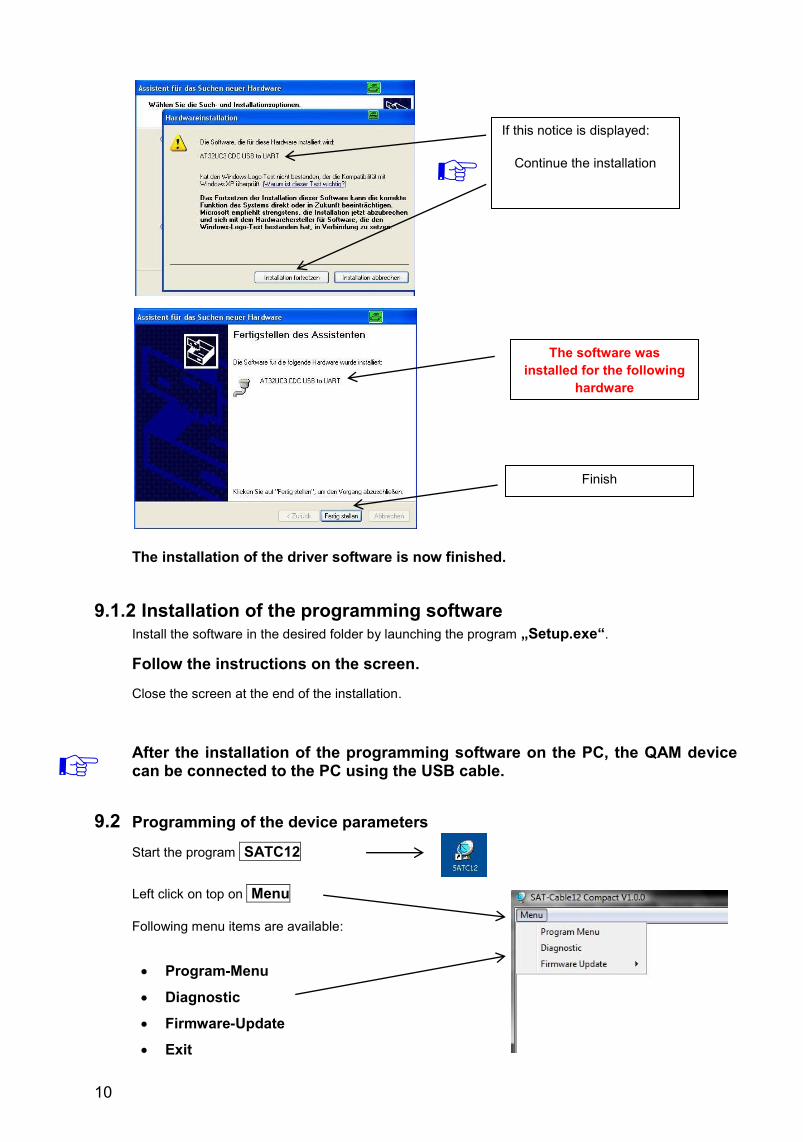
9.2 Programming of the device parameters
Start the program SATC12
Left click on top on Menu
Following menu items are available:
Program-Menu
Diagnostic
Firmware-Update
Exit
If this notice is displayed:
Continue the installation
The software was
installed for the following
hardware
Finish
11
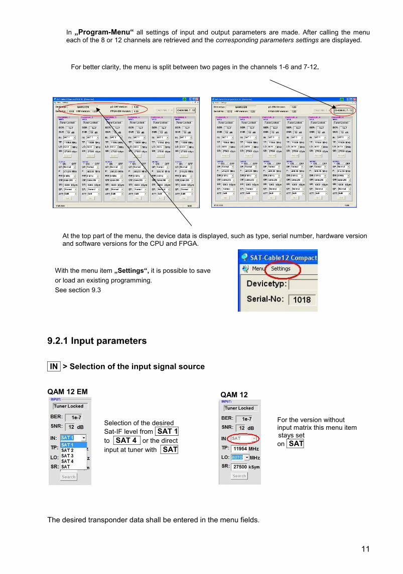
In „Program-Menu“ all settings of input and output parameters are made. After calling the menu each of the 8 or 12 channels are retrieved and the corresponding parameters settings are displayed.
For better clarity, the menu is split between two pages in the channels 1-6 and 7-12.
At the top part of the menu, the device data is displayed, such as type, serial number, hardware version and software versions for the CPU and FPGA.
With the menu item „Settings“, it is possible to save
or load an existing programming.
See section 9.3
9.2.1 Input parameters
IN > Selection of the input signal source
QAM 12 EM
Selection of the desired
Sat-IF level from SAT 1
to SAT 4 or the direct
input at tuner with SAT
QAM 12
For the version without input matrix this menu item Menüp stays set
on SAT
The desired transponder data shall be entered in the menu fields.
12
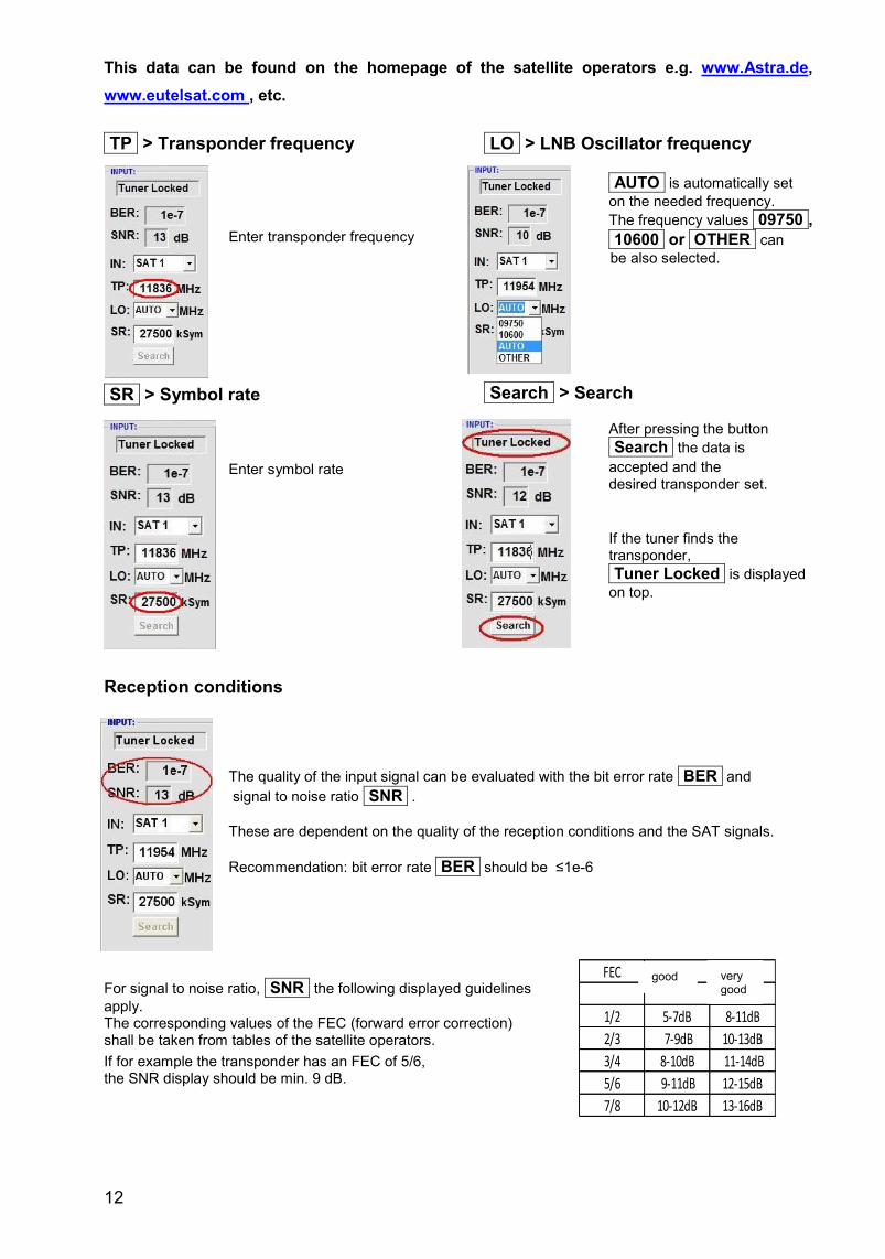
This data can be found on the homepage of the satellite operators e.g. www.Astra.de,
www.eutelsat.com , etc.
TP > Transponder frequency
Enter transponder frequency
LO > LNB Oscillator frequency
AUTO is automatically set
on the needed frequency.
The frequency values 09750 ,
10600 or OTHER can
c be also selected.
SR > Symbol rate Enter symbol rate
Search > Search After pressing the button
Search the data is
accepted accepted and the
desired transponder set.
If the tuner finds the transponder,
Tuner Locked is displayed
on top.
Reception conditions
The quality of the input signal can be evaluated with the bit error rate BER and
signal to noise ratio SNR .
These are dependent on the quality of the reception conditions and the SAT signals.
Recommendation: bit error rate BER should be ≤1e-6
For signal to noise ratio, SNR the following displayed guidelines
apply. The corresponding values of the FEC (forward error correction) shall be taken from tables of the satellite operators.
If for example the transponder has an FEC of 5/6, the SNR display should be min. 9 dB.
FEC gut sehr gut
1/2 5-7dB 8-11dB
2/3 7-9dB 10-13dB
3/4 8-10dB 11-14dB
5/6 9-11dB 12-15dB
7/8 10-12dB 13-16dB
good very good
13
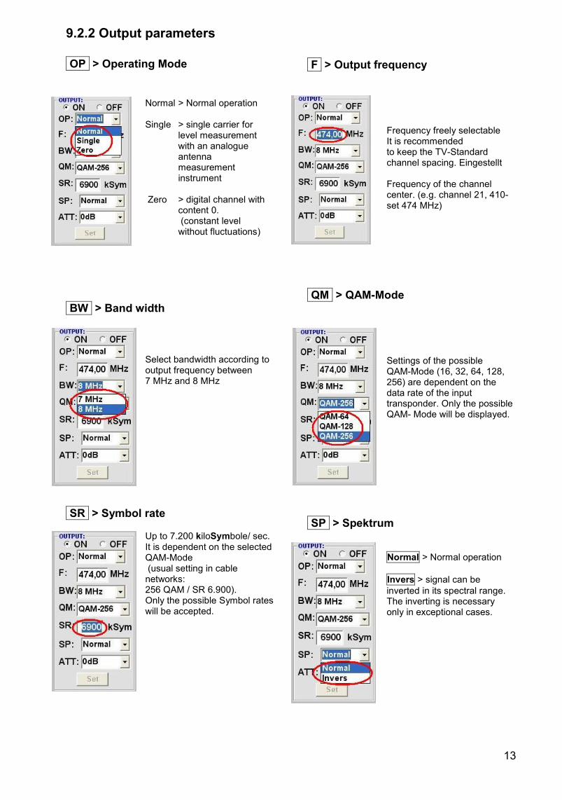
9.2.2 Output parameters
OP > Operating Mode
Normal > Normal operation Single > single carrier for level measurement with an analogue antenna measurement instrument Zero > digital channel with content 0. (constant level without fluctuations)
BW > Band width
Select bandwidth according to output frequency between 7 MHz and 8 MHz
SR > Symbol rate
Up to 7.200 kiloSymbole/ sec. It is dependent on the selected QAM-Mode (usual setting in cable networks: 256 QAM / SR 6.900). Only the possible Symbol rates will be accepted.
F > Output frequency Frequency freely selectable It is recommended
to keep the TV-Standard channe channel spacing. Eingestellt wird die
Frequency of the channel center. (e.g. channel 21, 410- 478 MHz, set 474 MHz)
QM > QAM-Mode Settings of the possible QAM-Mode (16, 32, 64, 128, 256) are dependent on the data rate of the input transponder. Only the possible QAM- Mode will be displayed.
SP > Spektrum
Normal > Normal operation
Invers > signal can be
inverted in its spectral range. The inverting is necessary only in exceptional cases.
14
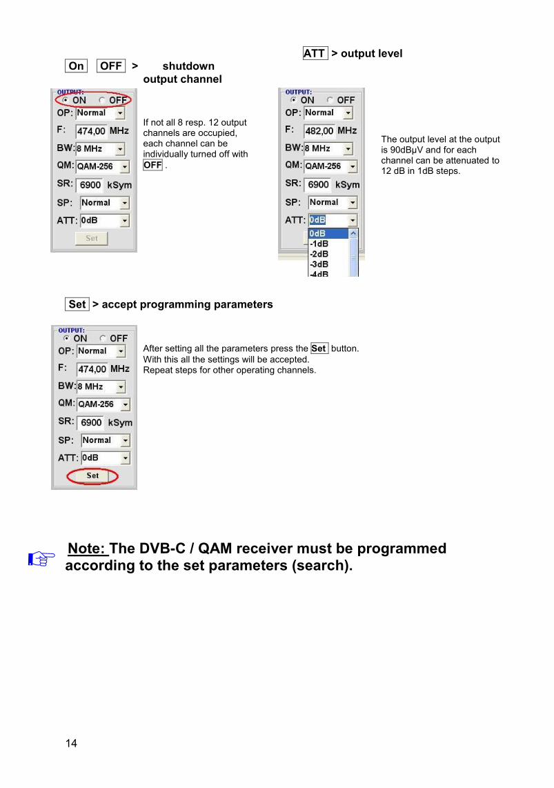
On OFF > shutdown
output channel
If not all 8 resp. 12 output channels are occupied, each channel can be individually turned off with
OFF .
ATT > output level
The output level at the output is 90dBµV and for each channel can be attenuated to 12 dB in 1dB steps.
Set > accept programming parameters
After setting all the parameters press the Set button.
With this all the settings will be accepted. Repeat steps for other operating channels.
Note: The DVB-C / QAM receiver must be programmed according to the set parameters (search).
15
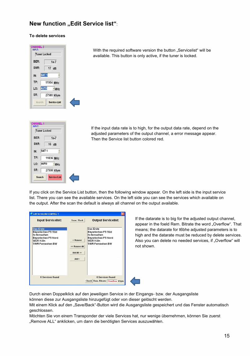
New function „Edit Service list“:
To delete services
If you click on the Service List button, then the following window appear. On the left side is the input service
list. There you can see the available services. On the left side you can see the services which available on
the output. After the scan the default is always all channel on the output available.
Durch einen Doppelklick auf den jeweiligen Service in der Eingangs- bzw. der Ausgangsliste
können diese zur Ausgangsliste hinzugefügt oder von dieser gelöscht werden.
Mit einem Klick auf den „Save/Back“-Button wird die Ausgangsliste gespeichert und das Fenster automatisch
geschlossen.
Möchten Sie von einem Transponder der viele Services hat, nur wenige übernehmen, können Sie zuerst
„Remove ALL“ anklicken, um dann die benötigten Services auszuwählen.
With the required software version the button „Servicelist“ will be
available. This button is only active, if the tuner is locked.
If the input data rate is to high, for the output data rate, depend on the
adjusted parameters of the output channel, a error message appear.
Then the Service list button colored red.
If the datarate is to big for the adjusted output channel,
appear in the foeld Rem. Bitrate the word „Overflow“. That
means; the datarate for t6bhe adjusted parameters is to
high and the datarate must be reduced by delete services.
Also you can delete no needed services, if „Overflow“ will
not shown.
16
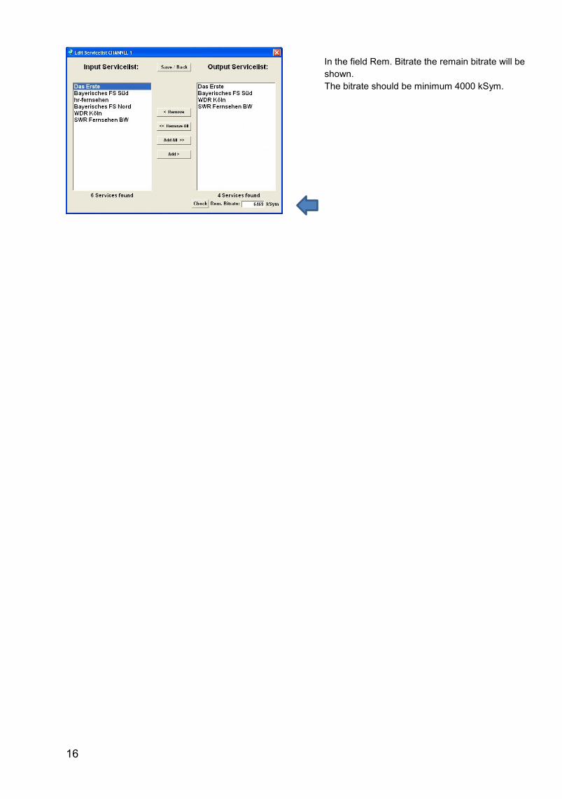
In the field Rem. Bitrate the remain bitrate will be
shown.
The bitrate should be minimum 4000 kSym.
17
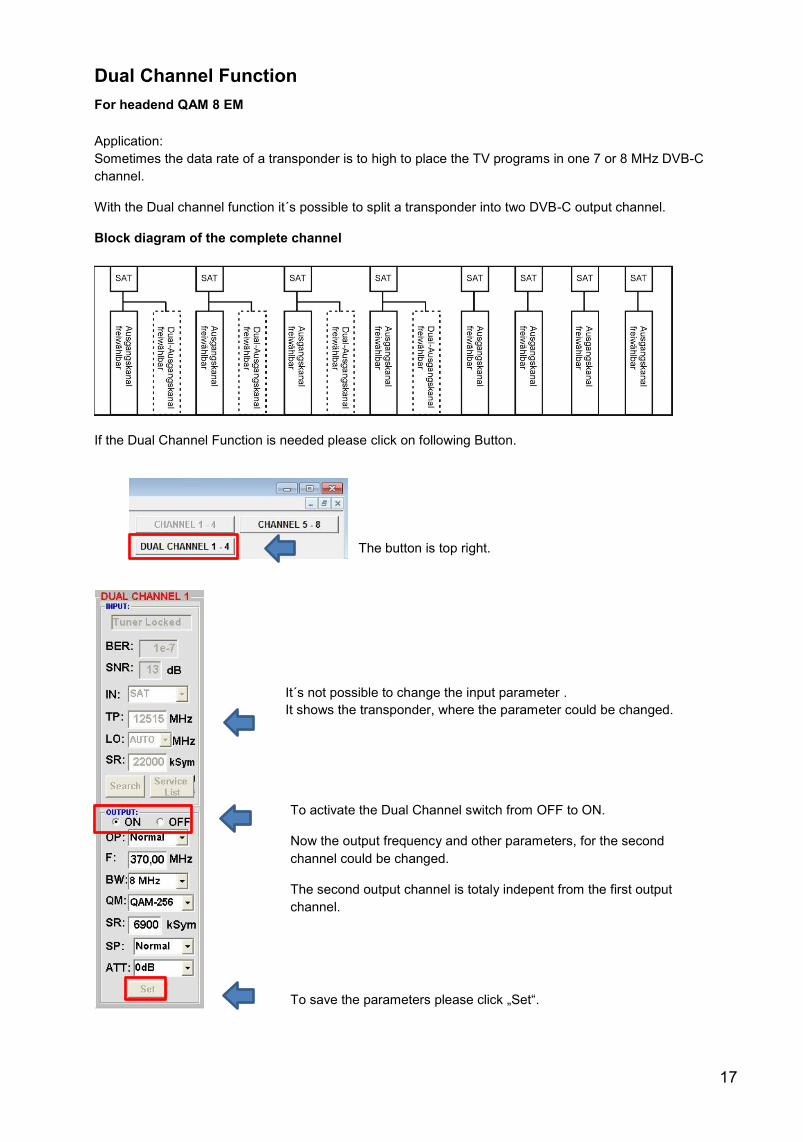
Dual Channel Function
For headend QAM 8 EM
Application:
Sometimes the data rate of a transponder is to high to place the TV programs in one 7 or 8 MHz DVB-C
channel.
With the Dual channel function it´s possible to split a transponder into two DVB-C output channel.
Block diagram of the complete channel
If the Dual Channel Function is needed please click on following Button.
To activate the Dual Channel switch from OFF to ON.
Now the output frequency and other parameters, for the second
channel could be changed.
The second output channel is totaly indepent from the first output
channel.
To save the parameters please click „Set“.
The button is top right.
It´s not possible to change the input parameter .
It shows the transponder, where the parameter could be changed.
18
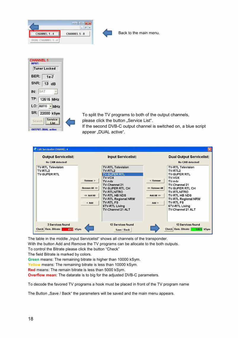
The table in the middle „Input Servicelist“ shows all channels of the transponder.
With the button Add and Remove the TV programs can be allocate to the both outputs.
To control the Bitrate please click the button “Check”
The field Bitrate is marked by colors.
Green means: The remaining bitrate is higher than 10000 kSym.
Yellow means: The remaining bitrate is less than 10000 kSym.
Red means: The remain bitrate is less than 5000 kSym.
Overflow mean: The datarate is to big for the adjusted DVB-C parameters.
To decode the favored TV programs a hook must be placed in front of the TV program name
The Button „Save / Back“ the parameters will be saved and the main menu appears.
Back to the main menu.
To split the TV programs to both of the output channels,
please click the button „Service List“.
If the second DVB-C output channel is switched on, a blue script
appear „DUAL active“.
19
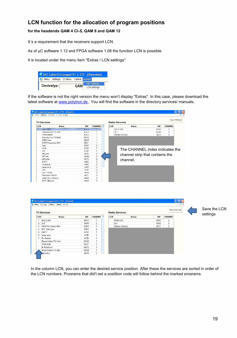
LCN function for the allocation of program positions
for the headends QAM 4 CI-S, QAM 8 and QAM 12
It´s a requirement that the receivers support LCN.
As of µC software 1.12 and FPGA software 1.08 the function LCN is possible.
It is located under the menu item "Extras / LCN settings"
If the software is not the right version the menu won’t display "Extras". In this case, please download the
latest software at www.polytron.de . You will find the software in the directory services/ manuals.
The CHANNEL index indicates the
channel strip that contains the
channel.
In the column LCN, you can enter the desired service position. After these the services are sorted in order of
the LCN numbers. Programs that did’t get a posittion code will follow behind the marked programs.
Save the LCN
settings
20
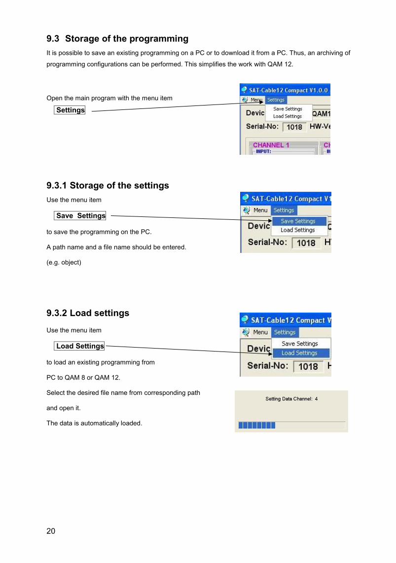
9.3 Storage of the programming
It is possible to save an existing programming on a PC or to download it from a PC. Thus, an archiving of
programming configurations can be performed. This simplifies the work with QAM 12.
Open the main program with the menu item
Settings
9.3.1 Storage of the settings
Use the menu item
Save Settings
to save the programming on the PC.
A path name and a file name should be entered.
(e.g. object)
9.3.2 Load settings
Use the menu item
Load Settings
to load an existing programming from
PC to QAM 8 or QAM 12.
Select the desired file name from corresponding path
and open it.
The data is automatically loaded.
21
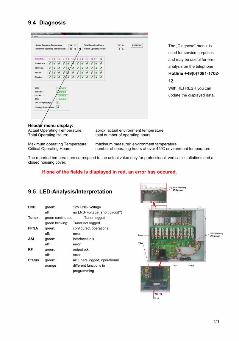
9.4 Diagnosis
The „Diagnose“ menu is
used for service purposes
and may be useful for error
analysis on the telephone
Hotline +49(0)7081-1702-
12.
With REFRESH you can
update the displayed data.
Header menu display: Actual Operating Temperature: aprox. actual environment temperature Total Operating Hours: total number of operating hours Maximum operating Temperature: maximum measured environment temperature Critical Operating Hours: number of operating hours at over 45°C environment temperature The reported temperatures correspond to the actual value only for professional, vertical installations and a closed housing cover.
If one of the fields is displayed in red, an error has occured.
9.5 LED-Analysis/Interpretation
LNB green: 12V LNB- voltage
off: no LNB- voltage (short circuit?)
Tuner green continuous: Tuner logged
green blinking: Tuner not logged
FPGA green: configured, operational
off: error
ASI green: interfaces o.k.
off: error
RF green: output o.k.
off: error
Status green: all tuners logged, operational
orange different functions in
programming
22
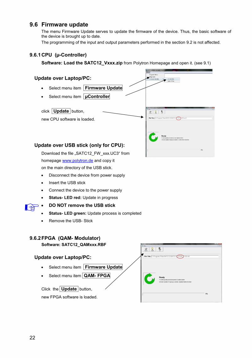
9.6 Firmware update The menu Firmware Update serves to update the firmware of the device. Thus, the basic software of the device is brought up to date.
The programming of the input and output parameters performed in the section 9.2 is not affected.
9.6.1 CPU (µ-Controller)
Software: Load the SATC12_Vxxx.zip from Polytron Homepage and open it. (see 9.1)
Update over Laptop/PC:
Select menu item Firmware Update
Select menu item µController
click Update button,
new CPU software is loaded.
Update over USB stick (only for CPU):
Download the file „SATC12_FW_xxx.UC3“ from
homepage www.polytron.de and copy it
on the main directory of the USB stick.
Disconnect the device from power supply
Insert the USB stick
Connect the device to the power supply
Status- LED red: Update in progress
DO NOT remove the USB stick
Status- LED green: Update process is completed
Remove the USB- Stick
9.6.2 FPGA (QAM- Modulator)
Software: SATC12_QAMxxx.RBF
Update over Laptop/PC:
Select menu item Firmware Update
Select menu item QAM- FPGA
Click the Update button,
new FPGA software is loaded.
23
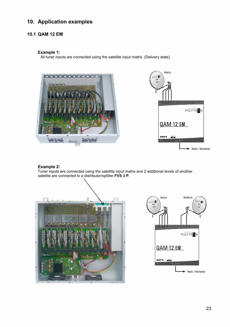
10. Application examples
10.1 QAM 12 EM
Example 1: All tuner inputs are connected using the satellite input matrix. (Delivery state)
Example 2: Tuner inputs are connected using the satellite input matrix and 2 additional levels of another satellite are connected to a distributor/splitter FVS 3 P.
24
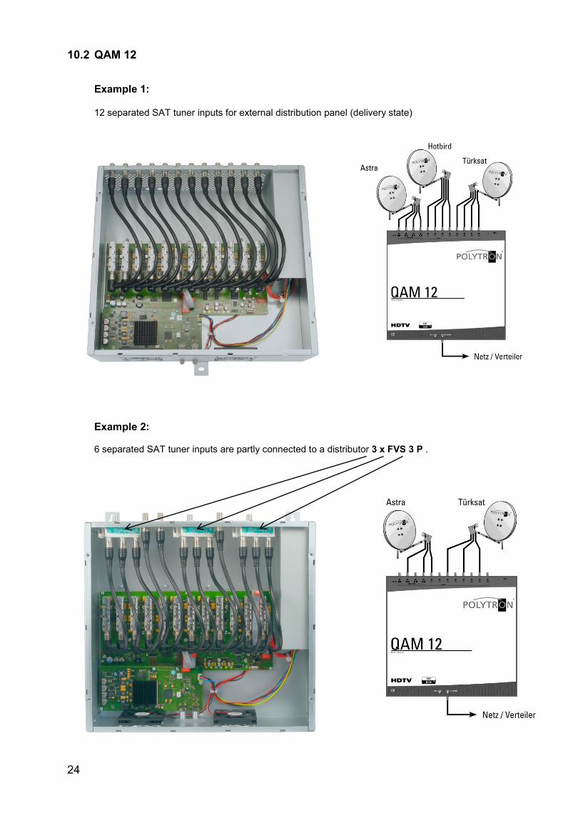
10.2 QAM 12
Example 1: 12 separated SAT tuner inputs for external distribution panel (delivery state)
Example 2: 6 separated SAT tuner inputs are partly connected to a distributor 3 x FVS 3 P .
25
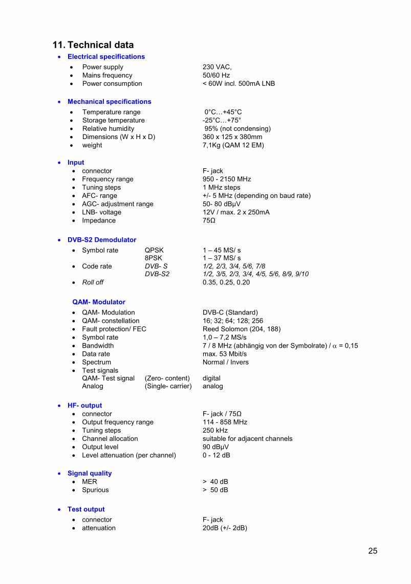
11. Technical data Electrical specifications
Power supply 230 VAC,
Mains frequency 50/60 Hz
Power consumption < 60W incl. 500mA LNB
Mechanical specifications
Temperature range 0°C…+45°C
Storage temperature -25°C…+75°
Relative humidity 95% (not condensing)
Dimensions (W x H x D) 360 x 125 x 380mm
weight 7,1Kg (QAM 12 EM)
Input
connector F- jack
Frequency range 950 - 2150 MHz
Tuning steps 1 MHz steps
AFC- range +/- 5 MHz (depending on baud rate)
AGC- adjustment range 50- 80 dBµV
LNB- voltage 12V / max. 2 x 250mA
Impedance 75Ω
DVB-S2 Demodulator
Symbol rate QPSK 1 – 45 MS/ s 8PSK 1 – 37 MS/ s
Code rate DVB- S 1/2, 2/3, 3/4, 5/6, 7/8 DVB-S2 1/2, 3/5, 2/3, 3/4, 4/5, 5/6, 8/9, 9/10
Roll off 0.35, 0.25, 0.20
QAM- Modulator
QAM- Modulation DVB-C (Standard)
QAM- constellation 16; 32; 64; 128; 256
Fault protection/ FEC Reed Solomon (204, 188)
Symbol rate 1,0 – 7,2 MS/s
Bandwidth 7 / 8 MHz (abhängig von der Symbolrate) / = 0,15
Data rate max. 53 Mbit/s
Spectrum Normal / Invers
Test signals QAM- Test signal (Zero- content) digital Analog (Single- carrier) analog
HF- output
connector F- jack / 75Ω
Output frequency range 114 - 858 MHz
Tuning steps 250 kHz
Channel allocation suitable for adjacent channels
Output level 90 dBµV
Level attenuation (per channel) 0 - 12 dB
Signal quality
MER > 40 dB
Spurious > 50 dB
Test output
connector F- jack
attenuation 20dB (+/- 2dB)
26
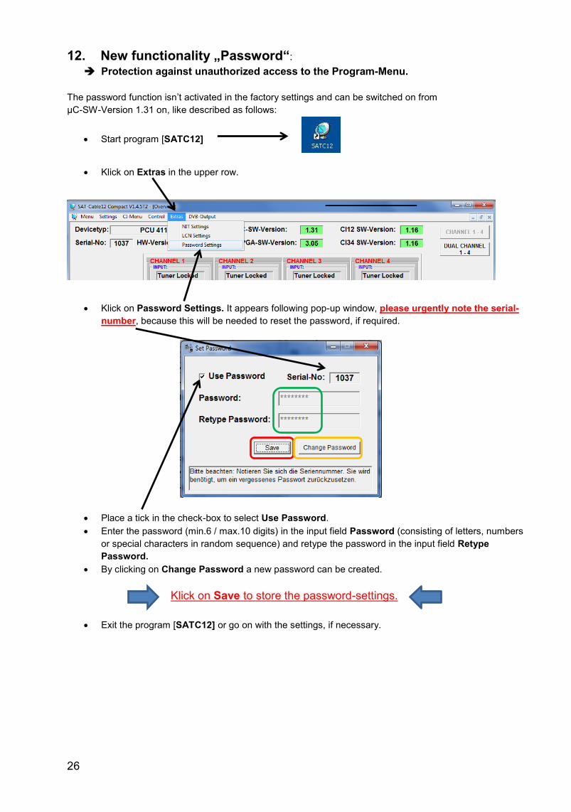
12. New functionality „Password“:
Protection against unauthorized access to the Program-Menu.
The password function isn’t activated in the factory settings and can be switched on from
µC-SW-Version 1.31 on, like described as follows:
Klick on Extras in the upper row.
Klick on Password Settings. It appears following pop-up window, please urgently note the serial-
number, because this will be needed to reset the password, if required.
Place a tick in the check-box to select Use Password.
Enter the password (min.6 / max.10 digits) in the input field Password (consisting of letters, numbers
or special characters in random sequence) and retype the password in the input field Retype
Password.
By clicking on Change Password a new password can be created.
Klick on Save to store the password-settings.
Exit the program [SATC12] or go on with the settings, if necessary.
Start program [SATC12]
27
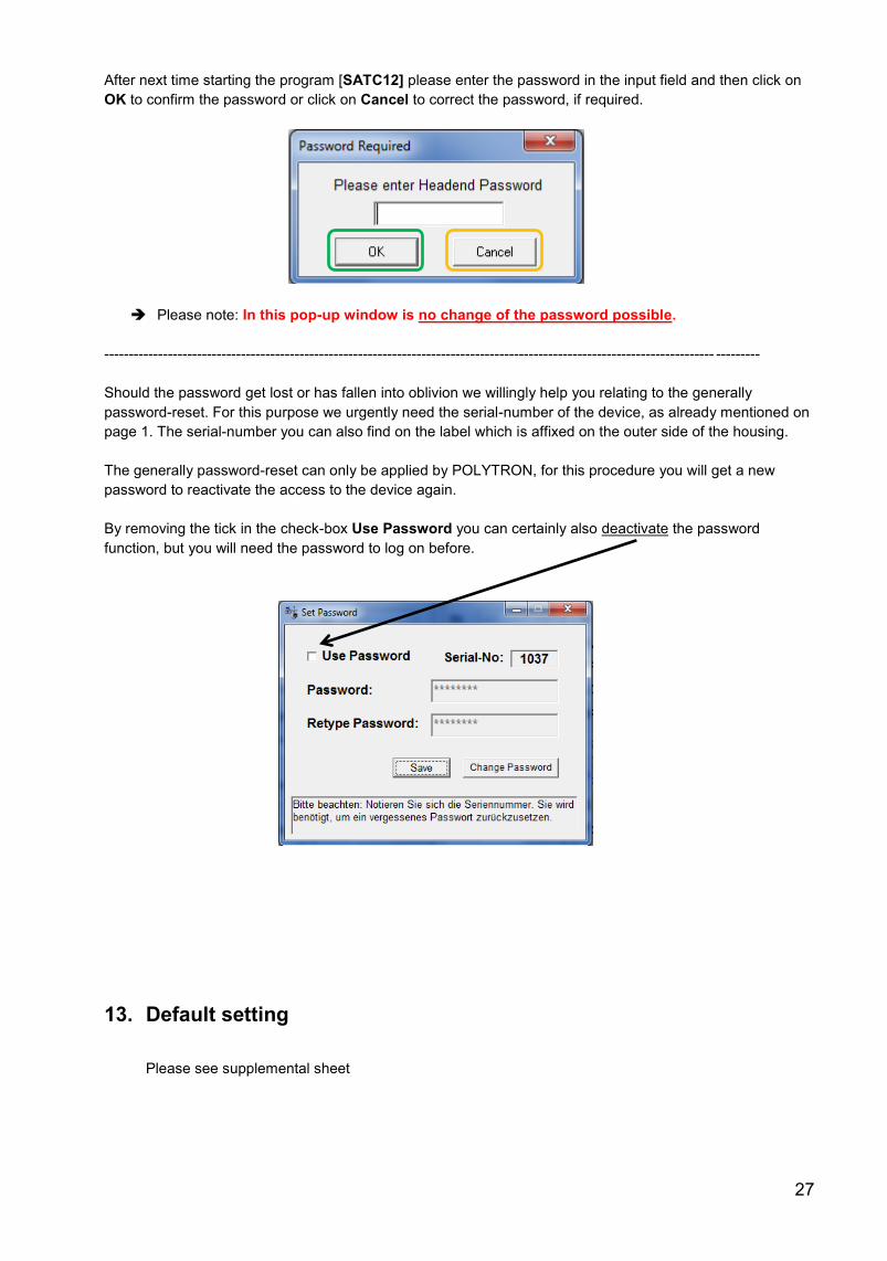
After next time starting the program [SATC12] please enter the password in the input field and then click on
OK to confirm the password or click on Cancel to correct the password, if required.
Please note: In this pop-up window is no change of the password possible.
----------------------------------------------------------------------------------------------------------------------------- ---------
Should the password get lost or has fallen into oblivion we willingly help you relating to the generally
password-reset. For this purpose we urgently need the serial-number of the device, as already mentioned on
page 1. The serial-number you can also find on the label which is affixed on the outer side of the housing.
The generally password-reset can only be applied by POLYTRON, for this procedure you will get a new
password to reactivate the access to the device again.
By removing the tick in the check-box Use Password you can certainly also deactivate the password
function, but you will need the password to log on before.
13. Default setting Please see supplemental sheet
28
Polytron-Vertrieb GmbH Postfach 10 02 33 75313 Bad Wildbad Zentrale/Bestellannahme H.Q. Order department + 49 (0) 70 81/1702 - 0 Technische Hotline Technical hotline + 49 (0) 70 81/1702 - 12 Telefax + 49 (0) 70 81) 1702 - 50 Internet http://www.polytron.de Email [email protected] Technische Änderungen vorbehalten Subject to change without prior notice Copyright © Polytron-Vertrieb GmbH