PYROMETALLURGICAL PROCESSES FOR RECOVERY OF …
30
PYROMETALLURGICAL PROCESSES FOR RECOVERY OF ACTINIDE ELEMENTS* J. E. Battles. J. J. Laidler, C. C. McPheeters, and W. E. Miller Chemical Technology Division Argonne National Laboratory Abstract A metallic fuel alloy, nominally U-20-Pu-1 OZr, is the key element of the Integral Fast Reactor (IFR) fuel cycle. Metallic fuel permits the use of an innovative, simple pyrometallurgical process, known as pyroprocassing, which features fused salt electrorefining of the spent fuel. Electrorefining separates the actinide elements from fission products, without producing a separate stream of plutonium. The plutonium-bearing product is contaminated with higher actinides and with a minor amount of rare earth fission products, making it diversion resistant while still suitable as a fuel material in the fast spectrum of the IFR core. The engineering- scale demonstration of this process will be conducted in the refurbished EBR-II Fuel Cycle Facility, which has entered the start-up phase. An additional pyrometallurgical process is under development for extracting transuranic (TRU) elements from light water reactor (LWR) spent fuel in a form suitable for use as a feed to the IFR fuel cycle. Four candidate extraction processes have been investigated and shown to be chemically feasible. The main steps in each process are oxide reduction with calcium or lithium, regeneration of the reductant and recycle of the salt, and separation of the TRU product from the bulk uranium. Two processes, referred to as the lithium and salt transport (calcium reductant) processes, have been selected for engineering-scale demonstra- tion, which is expected to start in late 1993. An integral part of pyroprocessing development is the treatment and packaging of high-level waste materials arising from the operations, along with the qualification of these waste forms for disposal in a geologic repository. Three waste streams arise from the processing of IFR and LWR fuels: fission product gases, metallic fission products, and salt containing chloride-forming fission products. The development of suitable waste forms for each waste stream is underway. 'Work supported by the U.S. Department of Energy, Nuclear Energy Research & Development Program, under Contract W-31-109-Eng-38. The by undt Ace norn Or com u.s submit! ) contr r cor rdingly xcluiiv cprodu ibution Goverr i;d manuscript h j i tx'en d .actor of the U S Gou( uaci No. W 31 10&E the U. S Gotft'tomotil r , royalty-frue licvmtjjo ,e the publishud Untr- ot allow oiticrs lo do muni purposes. litlioicd rntnont NG3B. <.i this SO, lor afc. -''• •>'- J V •.
Transcript of PYROMETALLURGICAL PROCESSES FOR RECOVERY OF …

PYROMETALLURGICAL PROCESSES FOR
RECOVERY OF ACTINIDE ELEMENTS*
J. E. Battles. J. J. Laidler, C. C. McPheeters, and W. E. Miller
Chemical Technology DivisionArgonne National Laboratory
Abstract
A metallic fuel alloy, nominally U-20-Pu-1 OZr, is the key element of the Integral Fast Reactor(IFR) fuel cycle. Metallic fuel permits the use of an innovative, simple pyrometallurgicalprocess, known as pyroprocassing, which features fused salt electrorefining of the spent fuel.Electrorefining separates the actinide elements from fission products, without producing aseparate stream of plutonium. The plutonium-bearing product is contaminated with higheractinides and with a minor amount of rare earth fission products, making it diversion resistantwhile still suitable as a fuel material in the fast spectrum of the IFR core. The engineering-scale demonstration of this process will be conducted in the refurbished EBR-II Fuel CycleFacility, which has entered the start-up phase.
An additional pyrometallurgical process is under development for extractingtransuranic (TRU) elements from light water reactor (LWR) spent fuel in a form suitable for useas a feed to the IFR fuel cycle. Four candidate extraction processes have been investigatedand shown to be chemically feasible. The main steps in each process are oxide reduction withcalcium or lithium, regeneration of the reductant and recycle of the salt, and separation of theTRU product from the bulk uranium. Two processes, referred to as the lithium and salttransport (calcium reductant) processes, have been selected for engineering-scale demonstra-tion, which is expected to start in late 1993.
An integral part of pyroprocessing development is the treatment and packagingof high-level waste materials arising from the operations, along with the qualification of thesewaste forms for disposal in a geologic repository. Three waste streams arise from theprocessing of IFR and LWR fuels: fission product gases, metallic fission products, and saltcontaining chloride-forming fission products. The development of suitable waste forms for eachwaste stream is underway.
'Work supported by the U.S. Department of Energy, Nuclear Energy Research & DevelopmentProgram, under Contract W-31-109-Eng-38.
T h e
byundtAcenornOr
comu.s
submit!) contr
r corrdinglyxcluiiv
cproduibutionGoverr
i;d manuscript h j i tx'en d.actor of the U S Gou(
uaci No. W 31 10&Ethe U. S Gotft'tomotil r
, royalty-frue licvmtjjo,e the publishud Untr-
ot allow oiticrs lo do
muni purposes.
litlioicdrntnont
NG3B.
<.i th isSO, l o r
afc. -''• •> ' - J V • .

I. Introduction
During the Manhattan Project in the 1940s, processes were developed for recovery of
actinide elements. The principal objective was the recovery and purification of plutonium from
reactor-irradiated uranium for military applications. Many physical and chemical methods were
investigated for the separation of uranium, plutonium, and fission products from one another.
These methods included ion exchange, solvent extraction, distillation, precipitation,
electrodeposition, and various metallurgical techniques. Because of the intended application and
the need for hands-on work with the uranium and plutonium products, the process had to provide
a high degree of separation of uranium and plutonium from high-radiation-level fission products.
Precipitation, ion exchange, or organic solvent extraction from aqueous solutions provided the
necessary separation and appeared to be the simplest to accomplish. By the early 1950s,
aqueous processes (bismuth phosphate, Redox, PUREX, etc.) capable of achieving nearly
complete recovery and decontamination had been developed. These processes were developed
for recovery of military-quality fissionable material; they are complex, requiring many steps and
massive installations. The development of commercial nuclear reactors in the 1950s and 1960s
for electrical generation promoted further interest in the processing of nuclear fuels (mostly
oxides). Today, the PUREX-type process is the principal method for processing commercial
nuclear fuels as well as irradiated fuels for military applications. The process yields a high-purity
plutonium product free of fission products and minor actinides (np, Am, Cm); the minor actinides
are part of the aqueous waste stream along with other fission products. TransLH-anic extraction
(TRUEX) is another aqueous process that is being developed specifically for the purpose of
recovering the minor actinides from the waste stream.

3
As noted above, the aqueous processes for fuel recycle are complex and require massive
installations. As early as the 1950s, much simpler fuel cycles were thought to be feasible for the
recycle of fast reactor fuel, since higher decontamination from thermal-neutron-absorbing fission
product nuclides would not be necessary. However, this would require that the fuel be processed
and refabricated by remote operations. Development of such a process was undertaken by
Argonne National Laboratory in the 1950s as part of the EBR-II program (Experimental Breeder
Reactor number two) (1), for which the reactor was co-located with a fuel cycle facility (Fig. 1).
The method for processing the metallic spent fuel was termed the melt refining process
(2,3). This involved a melt down of irradiated fuel pins, after they were declad and chopped into
short lengths in a calcia-stabilized zirconia crucible. Ten to twelve kilogram batches were melted
and liquated in the crucible for three hours at 1400°C. The metal was then chill cast into an ingot
by top pouring into a cold graphite mold. The average pouring yield for 500 runs was 92.3%.
In melt refining, the inert gaseous fission products Xe and Kr are given off to the melting furnace
atmosphere when the alloy melts. Volatile sodium, the metal fission products Cs and Rb, and
volatile iodides reacted with and were trapped as solids on a fume trap, which closed off the top
of the melting crucible. Rare earth and alkaline earth fission product metals reacted with the
crucible wall to form a skull, which stayed in the crucible when the melt was poured. The skull
trapped some metal, which became part of the skull and accounted for the 92.3% pouring yield.
During 1964-1969, 5.9 metric tons of irradiated fuel pins were processed into about 35,000 new
fuel elements, which were recycled to the reactor. The shortest cycle time was about 28 days,
i.e., the time from discharge from the reactor until recharge in the reactor.
The skull reclamation process (4) was developed to recover the enriched uranium in the

rPIN\ PROC.
r VISUALINSPECT.
TRANSFER7 DISMANTLEi TRANSFERPORTS / / LOCKS
r-rL
/ 7ASSEMBLE L BOND a L LEAK
TEST DETECT DECAN
RETORT
Figure 1 - Fuel Cycle FacilitySchematic for Melt Refiningand Skull Reclamation
4
crucible skulls. The melt refining skulls were oxidized within the zirconia crucible to create a free-
flowing powder which was then poured from the crucible. The oxide was then mixed with a
molten salt flux and liquid zinc at 75C°C in a tungsten crucible. The liquid zinc phase layer
containing the noble metal fission products was then removed from the crucible, and a reductant
(Mg-17 at. % Zn) for uranium oxide was introduced into the tungsten crucible. Insoluble uranium
metal precipitate formed, and the liquid flux and zinc phases containing fission products were
removed. The uranium precipitate was dissolved in a Mg-30 at. % Zn alloy. This liquid solution
was removed from the tungsten crucible and retorted, and then the residual uranium was melted
in the BeO crucible from which the uranium ingot was recovered. This process required three
major equipment items: a skull oxidation furnace, an oxide processing furnace with a tungsten
crucible and a Mo-W liquid zinc transfer line, and a uranium retort-melter. All of these items were
developed, but only the skull oxidation furnace was installed in the hot cell and used to separate
the enriched uranium skull from the zirconia crucible scrap.
In 1969 fuel processing and fuel fabrication activities in the Fuel Cycle Facility ceased.
At that time, the mission of EBR-II was changed from a demonstration of the integrated reactor-
reprocessing complex to that of an irradiation facility, with emphasis on oxide rather than metal
fuel. Interest in metal fuel was rekindled in the 1980s when metal fuel designers overcame the
primary objection to metal fuel, namely, that it was limited {due to swelling) to 1 % burnup or less.
(Burnups of 20% have now been achieved in U-Pu-Zr fuel.) This early work in developing
pyroprocesses for metal fuel emphasized uranium recovery because of the value of the enriched
uranium involved. Present-day processes emphasize the recovery of plutonium since the trend
is away from utilizing enriched uranium in fast reactor fuel.

5
The introduction of the Integral Fast Reactor (IFR) concept by Till and Chang (5) in the
1980s has generated new interest in the development of a simple, low decontamination,
economical fuel cycle based on pyrornetallurgical processing methods. The IFR is an advanced-
reactor concept proposed by and under development at Argonne National Laboratory. Further,
the fuel cycle is an integral part of the IFR, hence the basis for the name. In addition to the
integral fuel cycle, the IFR concept features a sodium-cooled pool-type reactor employing a
metallic alloy fuel of U, Pu, and Zr. Expected advantages of this concept are an exceptionally
high degree of passive safety and competitive economics resulting from low cost for reactor
construction and fuel recycle. The fuel cycle, which is a key element in the IFR concept, is based
on a pyrometallurgical process which employs electrorefining with a molten salt electrolyte (LiCI-
KCI-U/PuCy at 500°C in an inert atmosphere enclosure (6, 7). Process development using
simulated fuels has been conducted at Argonne-East and will be discussed in Section II.
Demonstration of the fuel cycle will take place at Argonne-West in the refurbished FCF (i.e., after
facility upgrade and changes in process equipment) and will utilize spent metallic fuel from EBR-II,
which is located adjacent to the FCF.
Development of a unique pyrometallurgical process for the recovery of the transuranic
(TRU) elements from irradiated oxide fuels was initiated in 1990 (8) as a means of providing a
source of plutonium for the startup of additional IFRs. This low-decontamination process, which
is discussed in Section III, will provide a plutonium alloy containing some uranium, the minor
actinides, and rare earth fission products as a fuel for the IFR fuel cycle. This aspect has
important beneficial implications on the disposal of commercial spent fuel. As discussed in
Section IV, the treatment, immobilization, and safe disposal of waste have been important
components of the IFR program from the beginning. This approach is believed to be a first in the

development of nuclear reactors.
II. Pyrometallurgical Processing of IFR Metallic Fuel
The basis of the IFR concept is the metal fuel cycle, which involves irradiation of metal
fuel (U-Pu-Zr alloy) in a fast reactor, reprocessing of the spent fuel, treatment and immobilization
of the waste, and refabrication of fuel elements. A key element in the processing of spent fuel
is a pyrometallurgical process which employs electrorefining with a molten salt electrolyte (LiCI-
KCI-U/PuCI3) at 500°C in a steel vessel (6, 7, 9). The abundant information developed at
Argonne in the 1960s on the thermodynamics of uranium-plutonium-fission product-cadmium
systems, in combination with subsequent work on molten salt batteries, provided the basis for the
development of an innovative electrorefining process for the reprocessing of IFR fuels.
Although electrorefining has not been used to date in the commercial reprocessing of
reactor fuels, this technology has a long history in commercial operations, the refining of
aluminum being a prime example. On a lesser scale, electrorefining from molten salts has been
used to prepare high-purity metallic uranium (10-12). Larger scale operations (5 to 10 kg U per
batch) were conducted by Chauvin and co-workers (13, 14) in France during the early 1960s.
High-purity plutonium for research purposes has also been prepared by molten salt electrorefining
(15, 16). Subsequently, Mullins and co-workers at Los Alamos (17-J9) developed an
electrorefining process for recovery and purification of plutonium. This process has also been
used at Lawrence Livermore National Laboratory (20) and at the Rocky Flats Plant (21) for the
purification of plutonium. As evidenced by the above, significant research and development has
been devoted to electrorefining of uranium and plutonium separately. Very little work has been
7
done on developing electrorefining for recovery and purification of spent nuclear fuels in the U.S.
In the mid-1950s electrorefining was investigated at Knolls Atomic Power Laboratory for
decontamination of irradiated uranium (22, 23). Leary, et al (24) investigated electrorefining for
reprocessing fuel from the Los Alamos Molten Plutonium Reactor Experiment (LAMPRE). This
fuel was successfully electrorefined at 550°C using a LiCI-KCI-PuCI3 electrolyte.
The potential application of electrorefining for processing IFR metal fuel is obvious from
the above discussion. However, it is important to note that IFR fuel has a complex composition,
involving U-Pu-Zr alloy with associated fission products. The electrorefining process (also called
pyroprocess) for IFR fuel is based on the favorable thermodynamics of the chlorides and the
concomitant use of liquid cadmium as a solvent for the metal fuel and as one electrode of the
electrorefining cell. A simplified schematic of the electrorefining apparatus is shown in Fig. 2.
The cell vessel, fabricated from carbon steel, contains a layer of liquid cadmium with an over-
layer of eutectic LiCI-KCI electrolyte (melting point ~350°C). The operating temperature is
normally 500°C but can be lower (<450°C). For startup, the clad fuel elements*[Footnote:
Unirradiated simulated fuel has been used in all of tne process development work. Processing
of irradiated fuel is scheduled for 1994 in the shielded EBR-II Fuel Cycle Facility.] are chopped
and placed in perforated steel anode baskets and lowered into the electrolyte for electrochemical
dissolution. Initially, the plan was to dissolve the fuel in the cadmium pool; however, this was
abandoned in favor of the more rapid electrochemical dissolution (future electrorefiners may not
contain a cadmium pool). With the chopped fuel in the salt, cadmium dichloride (CdCI2) is added
to oxidize the alkali, alkaline earth, and most of the rare earth elements to their chlorides.
Additional CdCI2 is added to oxidize the actinide elements to obtain a concentration of about 6
wt % actinides in the electrolyte to sustain electrotransport.

Schematic Representation of Electro refinerOperation - Anodic Dissolution/Solid Cathode
Low-Carbon •Steel Vessel
Anodic Dissolution -Basket
Core and/or Blanket-Fuel, Clad, andNa Bond
Metal Waste(Clad, Cd, N.M. FPs)
Xe, Kr
CellElectrolyte
Cadmium Anode (500° C)
*• Cathode Product toProduct Consolidation(U, Cd, Salt)
Solid Cathode
•> Salt WasteElectropositiveFPs, I as T andNa as NaCI
Figure 2

8
The partitioning of the actinides, alloy zirconium, and fission products is controlled by the
thermodynamics of the respective chlorides. As indicated by the data in Table I, the free energies
of formation allow separating the elements of interest into three groups: high stability, e.g., alkali,
alkaline earth, and lanthanidss; low stability, i.e., elements that do not form chlorides in this
system; and intermediate stability, i.e., U, Np, Pu, Am, and Cm (zirconium is a borderline case).
The actinide elements partition between the salt and metal phases and thus can be
electrotransported. The oxidation state of the electrorefiner can be adjusted by adding an oxidant
(CdCI2) or a reductant (Li-Cd alloy).
Table 1.
Compound
BaCI2
CsCI
RbCI
KCI
SrCI2
LiCI
NaCI
CaCl2
Free Energies of Formation of Chlorides
at 500°C, 1
-AGt°
87.9
87.8
87.0
86.7
84.7
82.5
81.2
80.7
<cal/g-equiv. chlorine
Compound
CmClg
PuOtg
NpCI3
va3
ZrCf2
CdCl2
FeCI2
NbCI5
-AGf°
$4,0
62.4
58.1
55.2
46.6
32.3
29.2
26.7

LaCI3
PrCI3
CeCI3
NdCI3
YCI3
70.2
69.0
68.6
67.9
65.1
9
MoCI4
TcCI4
RhCI3
PdCI2
RuCI4
16.8
11.0
10.0
9.0
6.0
In operation, uranium is electrotransported to a steel mandrel cathode, where it deposits
as metallic dendrite. A typical product is shown in Fig. 3. This product normally contains a low
concentration of zirconium (1 to 2 wt %). The TRU elements do not deposit because their
chlorides and uranium are in equilibrium according to the reaction,
UCI3 + Pu —> U + PuCI3. (1)
A liquid cadmium cathode is used for the recovery of plutonium and the other TRU elements.
This cathode consists of a ceramic crucible containing liquid cadmium, which is suspended in the
salt. Electrical contact with the cadmium in the ceramic crucible is provided by a steel electrode.
The plutonium and other TRU elements are electrotransported to the cadmium in the ceramic
crucible, where they form intermetallic compounds such as PuCd6. The activity of the TRU
elements is sufficiently decreased by the formation of intermetallics that they are stable in the
presence of UCI3 in the salt. The product obtained from this operation contains about 3 kg of
plutonium; 1 kg of uranium; the associated Np, Am, and Cm (all of which behave like Pu); and
a small amount of lanthanide fission products. The low decontamination of this process is
beneficial since it adds a significant measure of diversion resistance. The cadmium is distilled

Ten Kilogram Uranium Deposit

10
from the liquid cathode product, and the resulting plutonfum-bearing alloy along with the uranium
product from the solid cathode (after distilling off the adhering salt) is added to a furnace for the
casting of new fuel elements.
A process model based on thermodynamic data has been developed for predicting the
electrotransport of uranium, pfutonium, and rare earth fission products (25). The model also
predicts the composition of the solid cathode and liquid cadmium cathode. A series of
experiments was conducted for model verification. The results of these experiments indicated
that little or no rare earths are deposited with uranium; the uranium deposit is essentially free of
Plutonium and other actinides until the uranium inventory reaches a low level; the minor actinides
(Np, Am, Cm) follow plutonium; and minor quantities of zirconium are electrotransported. The
agreement between this observed behavior and that predicted by the model was very good.
in addition to the laboratory-scale electrorefiner used to develop process feasibility and
determine process parameters, an engineering-scale electrorefiner facility (capacity of 10 kg of
uranium per single solid cathode) was constructed and operated (9) to demonstrate large-scale
operation, determine process parameters, and provide design information for the electrorefiner
to be placed in the FCF (26). The engineering-scale electrorefiner has operated continuously at
500°C for more than 5 yr with only minor maintenance. All of the process operations (anodic
dissolution, uraniurr deposition on solid and liquid cadmium cathodes) have been successfully
demonstrated, and the operating parameters quantified. Anodic dissolution and transport to the
solid cathode require about 24 h for a 10 kg batch of uranium. The FCF electrorefiner will
possess two anodes and two cathodes, with an expected process rate of 20 kg of uranium in a
24 h period. Systems analyses indicate that optimization of the electrorefiner design will increase
11
this process rate by a factor of four or more.
Electrotransport to the liquid cadmium cathode has been successfully demonstrated for
uranium-plutonium (plus minor actinides) in the laboratory-scale electrorefiner and for uranium
alone in the engineering-scale electrorefiner. The electrotransport rate to the liquid cadmium
cathode was less than that to the solid cathode, primarily because of a smaller area for
deposition. Both types of cathode products have been processed to distill off adhering salt and
cadmium (liquid cadmium cathode). Analyses demonstrated that the product is essentially free
of salt and cadmium impurities.
The pyroprocessing of spent IFR fuel produces three waste streams (see Fig. 2): fission
product gases, a metal waste stream that contains clad hulls and ncble mete! fission products,
and a salt waste stream that contains the rare earth, alkali, and alkaline earth fission products.
The treatment, immobilization, and disposal of these wastes are discussed in Section IV.
III. Pyrometallurgical Processing of Oxide Fuel
Pyrochemical processes have been developed for extracting TRU elements from Light
Water Reactor (LWR) spent fuel in a form suitable for use as feed to the IFR fuel cycle (27). This
spent fuel, with a typical burnup of 33 GWd/MTIHM (gigawatt-days per metric ton initial heavy
metal), contains about 97 % uranium and about 1 % TRU elements, with fission products
comprising the balance. Tha goals of the process development include >99.9 % recovery of the
TRU elements, minimum quantity of waste to be placed in a geological repository, a simple
process with promising economics, and minimum risk of diversion of TRU elements to military
uses. The candidate pyrochemical processes are based on work that was done at ANL in the
1960s and 1970s (28-30). Four essential features are critical to meeting the processing goals:

12
(1) the oxide fuel is reduced to metal components, using a reductant metal such as calcium or
lithium, (2) the reductant metal oxide is dissolved in a molten salt phase, so that the reduction
reaction can go to completion, (3) the reductant metal is regenerated by electrolysis to allow the
molten salt to be recycled, thus minimizing wastes, and (4) the TRU metals are separated from
uranium and consolidated into a product suitable for use in the IFR fuel cycle.
The generalized flowsheet for the pyrochemical process is shown in Fig. 4. The LWR
spent fuel subassemblies are disassembled, and the oxide fuel is separated from most of the
Zircaloy cladding before feeding to the process. The main steps in the generalized flowsheet
include reduction of the oxides, regeneration of the reductant metal and recycle of the salt,
separation of the TRU product from the bulk uranium, and evaporation of a solvent metal from
the TRU product for consolidation into a metal ingot.
Four extraction concepts were studied: the salt transport process, the magnesium
extraction process, the zinc-magnesium process, and the lithium process. Although all of these
processes follow the generalized flowsheet of Fig. 4, there are important differences among them,
particularly in the TRU-uranium separation method. In addition, the lithium process differs from
the other three by the use of lithium as the oxide reductant. The other processes use calcium
reductant.
Laboratory-Scale Experimental Studies
Many small-scale experiments were done to determine the feasibility of each step of
the processes as unit operations. No attempt was made to integrate the process steps,
except that reactants from some experiments were used as starting materials for subsequent
steps in the process. The types of experiments and their results are summarized in the
following sections.
Reductions. Reduction experiments were conducted using the molten salt and liquid
metal phases for each of the process concepts. The experiments were done in MgO crucibles
about 57-mm dia by 125-mm tall. In studies of the lithium process, stainless steel crucibles
were used. The crucibles were well baffled to enhance mixing. The reactants (salt, metal

ACTINIDE RECYCLE PYROPROCESS CONCEPT
Disassembly andDecladding
Oxide Reduction
TRU-UraniumSeparation
LWR Spent Fuel
co/co2
ISalt Electrolysis
Salt Waste
Solvent MetalEvaporation
•> Metal Waste
Halide Slaggingor Electrorefining
TRU ProductUranium
Figure 4 - Generalized Flowsheet for Pyrocnemical Processingof LWR Spent Fuel

13
alloy, calcium or lithium, and the oxide simulated spent fuel) were loaded into the crucibles at
room temperature. The simulated fuel was added as chips of high-fired UO2 that contained
prototypical quantities of Pu, Am, and nonradioactive isotopes of the fission products. The
calcium reductions were conducted at 800° to 850°C in MgO crucibles, and the lithium
reductions were done at 500° to 750°C in stainless steel crucibles. At the end of each
experiment, filtered samples of the liquid phases were taken using tantalum sample tubes with
tantalum frits welded in the ends. Table II summarizes the results achieved in many reduction
experiments for each process concept. The numbers are averages of several separate
experiments. The reduction step was found to be satisfactory for all of the candidate
processes. A reduciion "scrub" step may be needed to assure >99.9% recovery of the TRU
elements.
Table II. Percent of Reductions Achieved for Each Process Concept Studied
Oxide Reduced
UO2
PuO2
NpO2
AmO2
CmO2
Salt TransDOrt
(Cu-Mg-Ca)
(CaCI2 Salt)
100.0
99.8
99.8
99.9
99.99
Zn-Ma Process
(Zn-Mg-Ca)
<CaCI2 Salt)
99.9
99.7
99.6
99.9
Ma Extraction
(U-Fe + Ca)
(CaCI2 Salt)
100.0
99.6
99.8
97.0"
Lithium
(Li)
(LiCI-KCI Salt)
100.0
99.996
97.5*
99.982
99.986
Limited data available for NpO2, but trends suggest >99.9% reduction under conditions
similar to existing tests.
99.1 % in one experiment.
Uranium-Transuranium Separations. Differences among the methods used to separate
TRU elements from uranium comprise the major differences among the flowsheets. As its
name implies, the salt transport process uses a molten salt extraction and transport step to
14
effect this separation. The molten salt, MgCI2, is first equilibrated with the Cu-Mg reduction
alloy. Since the activity coefficients of the TRU elements are relatively high in the Cu-Mg alloy
and since the TRU chlorides are more stable than MgCI2, the distribution of the TRU elements
between the Cu-Mg alloy and the molten salt tends to favor higher concentrations of the TRU
elements in the molten salt. The molten salt is then transported through a heated transfer line
to a separate vessel containing Zn-Mg alloy. In the Zn-Mg alloy the activity coefficients of the
TRU elements are relatively low; therefore, the distribution of the TRU elements between the
Zn-Mg alloy and the molten salt tends to favor higher concentrations of the TRU elements in
the Zn-Mg alloy. Thus, a net transport of TRU elements is achieved from the Cu-Mg alloy to
the Zn-Mg alloy, and an equivalent amount of magnesium is transported in the opposite
direction. During operation of the salt transport process, the donor vessel, the acceptor
vessel, and the transfer fine are all maintained at about 800°C.
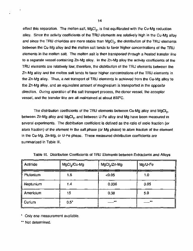
The distribution coefficients of the TRU elements between Cu-Mg alloy and MgCI2,
between Zn-Mg alloy and MgCI2, and between U-Fe alloy and Mg have been measured in
several experiments. The distribution coefficient is defined as the ratio of mole fraction (or
atom fraction) of the element in the salt phase (or Mg phase) to atom fraction of the element
in the Cu-Mg, Zn-Mg, or U-Fe phase. These measured distribution coefficients are
summarized in Table III.
Table III. Distribution Coefficients of TRU Elements between Extractants and Alloys
Actinide
Plutonium
Neptunium
Americium
Curium
MgCI^Cu-Mg
1.6
1.4
15
0.5*
MgCyZn-Mg
<0.05
0.036
0.38
**
Mg/U-Fe
1.0
0.05
5.0
**
* Only one measurement available.
** Not determined.

15
The combination of relatively high values for the MgCI2/Cu-Mg system and relatively
low values for the MgCI^Zn-Mg system indicates that the salt transport process should
provide efficient separation of the TRU elements from the bulk uranium. A small quantity of
uranium is transported with the TRU elements. Extraction of neptunium was found to be very
poor in the Mg/U-Fe system, as indicated by the low distribution coefficient. These data,
combined with the observation that the U-Fe alloy is very corrosive and difficult to contain in
normal materials of construction, led to the decision to eliminate the magnesium extraction
process from further consideration as a practical concept. Subsequent work concentrated on
the remaining three concepts.
In the lithium process the precipitated metal is separated from the reduction salt by
filtration or decanting of the molten salt from the crucible. At the end of the reduction step,
the uranium and TRU elements are present as metal precipitates at the bottom of the
reduction crucible, along with the transition metal and noble metal fission products. The metal
precipitate is transferred to an electrorefiner, and the uranium-TRU separation is done by the
electrorefining process, as discussed in Section II.
Salt Recycle. Two types of electrochemical cells have been tested for regeneration of
the calcium and lithium reductant metals: (1) a liquid Cu-Mg or Zn-Mg cathode and a carbon
anode and (2) a liquid lithium cathode and a carbon anode. Since lithium has a lower density
than the molten salt, it floats on the surface, whereas the calcium cathodes have a higher
density than the molten salt and remain on the crucible bottom.
Electrochemical reactions at carbon anodes have been shown to produce carbon
dusting. Because carbon reacts with uranium and TRU metals to form very stable carbides,
methods for controlling this carbon dust had to be developed. A porous ceramic (MgO)
shroud to surround the carbon anode was found to adequately contain the carbon dust and
prevent it from recycling with the salt. At the end of the salt regeneration step, the porous
shroud was raised out of the molten salt and allowed to drain. The shroud was placed in a
dry air environment and heated to ignite the carbon. The carbon dust burned off and the
shroud was clean enough for reuse in the process.

16
The results of many experimental tests of these types of electrochemical cells are
summarized in Table IV. The currant densities were higher for the zinc-magnesium cathode
than for the Cu-Mg cathode because the activity coefficient of calcium in the Zn-Mg alloy is
lower than in the Cu-Mg alloy. This lower activity coefficient decreases the theoretical
decomposition potential, thus increasing the available potential for the reaction. The current
density for the lithium process is higher than the other two processes because the difference
between the LiCI and Li2O decomposition potentials is greater than the difference between
CaCI2 and CaO; thus, the working potential is higher and the current density is greater. A
current density of 500 mA/cm2 would be required for a practical full-scale system, and any of
the systems shown in Table IV could achieve that level with proper cell design. The
differences in current efficiencies are not well understood. Current losses may be due to
chemical short-circuiting reactions that are diffusion limited. Current efficiency is not an
important parameter because the electricity costs are low relative to other operating costs.
Table IV. Results of Electrolysis of CaO and Li2O in Molten Salt Systems
Parameter
Cathode Material
Temperature,(°C)
Current Density(mA/cm2)
Current Efficiency(Percent)
Salt Transport
Cu-Mg
800
170
70
Zinc-Magnesium
Zn
800
250
85
Lithium
Li
650
540
91
Process Selection. Based on the performance of the process steps compared to the
goals of the process, the lithium process was selected as the reference flowsheet. The
advantages of the lithium process include lower operating temperature, less corrosive
environment allowing use of common materials of construction, and a salt waste that is
compatible with the IFR salt waste, eliminating the need for development of a separate waste
form. The salt transport process will be retained as a backup because it is well understood
and the most reliable in terms of chemical performance. As stated above, the magnesium
extraction process was rejected because of poor extraction of neptunium by magnesium from

17
the U-Fe alloy, and because of the corrosive nature of the U-Fe liquid alloy. The zinc-
magnesium process was rejected because it produces more salt waste than the others and
because achieving clean separation of the Zn-Mg alloy from the uranium precipitate may be
difficult.
Engineering-Scale Process Development
The processes that were developed in laboratory-scale experiments are being scaled
up for demonstration at a scale that is a significant fraction of a full-scale plant. The scale
that was chosen for this demonstration is 20 kg batch size. This scale is about 10 % of a full-
scale plant module, and such a design would address most of the engineering issues
associated with heating, containing, and transferring high-temperature process fluids and
reagents.
The engineering-scale experiments will be done in an inert gas (argon) environment to
prevent reaction of the molten salt, liquid metals, actinide metals, etc. with oxygen or moisture.
The argon enclosure, or glovebox, is shown in Fig. V., along with a small nitrogen glovebox
that is connected by means of a vacuum transfer lock. The gloveboxes are shown in plan
view, and the location of the process equipment is indicated in the legend. The system
design is flexible so that a variety of flowsheet concepts and equipment can be tested.
IV. Waste Management
An integral part of pyroprocessing development is the treatment and packaging of the
high-level wastes arising from the pyroprocessing operations, along with qualification of these
wastes for disposal in a geologic repository. Because the actinides are virtually absent from
the pyroprocess waste streams, the radiological toxicity of the pyroprocess waste is greatly
reduced beyond the 300-400 year period during which the shorter-lived fission products
disappear by radioactive decay. This could represent a significant advantage in the disposal
of nuclear wastes, making it easier to provide assurance of complete containment of the
radionuclides present in the waste (31). As pointed out by Ramspott et al. (32), the removal
of actinides provides an ability to predict future effects regarding the release of materials from

ENGINEERING-SCALE PROCESS GLOVEBOX
S
S
25'(7.6 m)-
S-P00
•TRANSFER LOCK ARGON ATMOSPHERE
LEGEND
NITROGENATMOSPHERE
V-I REDUCTION VESSELV-II ACCEPTOR VESSELV-III, V-IV CASTING STATIONSV-V RETORTV-VI OXIDATION FURNACE
STORAGE WELLSBAG-OUT PORTLARGE BAG-OUT PORT
AND STORAGE WELL
SPS-P
Figure 5 - Equipment Designations and Locations in theEngineering-Scale Process Gloveboxcs

18
a mined geologic repository that is unchallengeable; if the actinides are not present in the
waste, they cannot cause an effect.
The fission products extracted from spent fuel by pyroprocessing will be placed in
stable, leach-resistant waste forms with acceptable mechanical integrity for repository
disposal. These fission products appear in various waste streams: in the electrorefiner wastes
and in the waste salt from the reduction process used for recovery of actinides from the spent
oxide fuel. The pyroprocess waste treatment operations will concentrate these fission product
wastes and then immobilize them into the final waste forms. These operations are
summarized below.
As spent fuel batches are processed in the electrorefiner, fission products accumulate
in the electrorefiner vessel. Fission products of the alkaline earth, alkali metal, and rare earth
groups build up in the electrolyte salt. The transition metals (i.e., the more electrochemically
noble metals) tend to concentrate in the cadmium pool, remain as a sludge in the anode
basket, or remain with the cladding hulls. As these fission products accumulate, the heat load
due to their radioactive decay increases until it exceeds facility or equipment design limits. At
that point, it is necessary to remove the heat-generating elements. First, the heavy metals
present in the salt are recovered in a form suitable for subsequent reintroduction to the
electrorefiner, by a process known as "drawdown." After the drawdown operation, which
reduces the heavy metal content in the salt to less than 0.01 wt %, the salt and metal phases
are removed for treatment to recover the remaining TRU elements and remove a sufficient
quantity of fission products that the salt and cadmium can be recycled.
The spent salt (i.e., the salt phase after drawdown, or the salt from the oxide reduction
process) will contain fission products (such as Cs, Sr, I) and the rare earth elements, all in the
form of chlorides. This salt is first sent to an extraction step, where the molten salt is reacted
with a liquid U-Cd alloy. The extraction of the TRU elements is carried out in a multi-stage
centrifugal contactor at a temperature of 500°C. The (depleted) uranium reduces the
chlorides of the TRU elements, which are present at low concentrations in the salt, with the
TRU elements partitioning into the metal phase in metallic form. The TRU-bearing cadmium is
returned to the electrorefiner, where the TRU elements are subsequently recovered by

19
electrotransport from the cadmium pool. Initial experiments are in progress (33) to
characterize the separation efficiency of a single-stage contactor.
After extraction of the transuranics, the spent salt is sent to a stripping operation in
which the salt is reacted with a liquid Cd-Li alloy, again at a temperature of 500°C. The
lithium is a strong reductant and reduces all of the rare earth chlorides present in the salt; the
rare earths concentrate in the cadmium phase, which becomes a waste material, and most of
the salt can be recycled to the electrorefiner until the decay heat load builds up to such a level
that the alkaline earth and alkali metal fission products must also be removed. The removal
of the rare earth elements from the salt is necessary to reduce the heat load in the
electrorefiner; because they can be electrotransported with the actinide elements, the rare
earths in the salt must be maintained at comparatively low concentrations to avoid excessive
contamination of the heavy metal product. Experiments with the salt stripper have been
completed and reported recently (34). The results showed that the stripping process is
effective in reducing the concentration of rare earth fission product elements to very low
levels.
The stripped salt is next sent to an immobilization step, where the molten salt is
infiltrated through a zeolite column. The zeolite sorbs the fission products by two processes:
ion exchange and occlusion of salt molecules in the molecular cage of the zeolite structure.
The effluent salt is virtually free of fission products and can be recycled to the electrorefiner.
Initial measurements have shown that high fission product loadings in the zeolite can be
obtained: up to 25 wt % fission products is possible. After sorption of the fission products,
the waste-loaded zeolite pellets are subjected to a stream of hot argon gas to remove
adherent surface salt. Then, a small quantity of anhydrous zeolite powder is added to
immobilize any residual surface salt, and the waste-loaded zeolite is hot pressed. The
hot-pressing operation can be done with a small amount of added low-melting glass frit to
serve as an encapsulating and binding medium for the zeolite powder particles, or the zeolite
can be pyrolyzed to form a solid monolithic mineral waste, sodalite. The release of fission
products from the zeolite-based mineral waste under conditions of groundwater impingement
appears to be acceptably small. Representative leach rates for various elements from the
glass-bonded composite zeolite are shown in Table V, where it is seen that the normalized

20
elease rates are all lower than the screening criterion of 1 g/m2d.
Table V. Normalized release rates, L, for various constituents present in glass-bonded
zeolite waste form (35). Standard test in deionized water at 90°C, for 28 days.
Element
Cs
Sr
Al
Si
L, g/m2d
0.52
0.15
0.26
0.22
Element
B
Ba
Li
K
L, g/m2d
0.53
0.11
0.60
0.45
A similar comparison is not yet available for the leach resistance of the sodalite version
of the waste form, but tests with unconsolidated sodalite powders have shown leach rates
even lower than those obtained with the glass-bonded composite (35).
The spent cadmium from the electrorefiner and from the salt stripping step is also
treated in the IFR pyroprocess. These two streams are combined in a partitioning process
where the fission product-bearing cadmium is contacted with a molten Al-Cu alloy having little
solubility for cadmium. The fission products tend to precipitate in the Al-Cu phase as
intermetallic compounds, leaving the cadmium phase virtually free of fission products. The
cadmium is recovered by retorting and then recycled to the electrorefiner. The Al-Cu alloy,
now containing the transition metal, rare earth, and noble metal fission products, can be cast
directly into a waste container for repository disposal.
An alternative version of the metal waste form, also under development at this time,
incorporates the cladding hulls as the matrix material. Depending on starting fuel type, this
material can be either stainless steel or zirconium alloy. With this approach, a substantial
fraction of the original fuel assembly hardware can also be included in the waste form while
achieving minimum packaged waste volume for disposal.
21
Although the IFR waste treatment and packaging processes are at a relatively early
stage of development, they appear to be technically feasible and fully amenable to DOE
initiatives on waste volume minimization. These processes will ultimately be developed and
demonstrated at a large scale with simulated fission products, with confirmation of the
processes carried out on a somewhat smaller scale as part of the IFR Fuel Cycle
Demonstration.
V. Summary
Development of the technology for pyrometallurgica! processing of spent fuel from the
Integral Fast Reactor (or Advanced Liquid Metal Reactor) is progressing well. The technology
demonstration phase, in which recycle will be demonstrated with irradiated fuel from the EBR-
II reactor, has been initiated in the refurbished EBR-II Fuel Cycle Facility. Methods for
recovering actinides from spent LWR fuel are at an earlier stage of development but appear to
be technically feasible. The processes developed for recycling valuable spent fuel materials
promise to provide substantial economic incentives for future applications of the technology,
perhaps including the treatment of the DOE spent fuel that is now awaiting permanent
disposal.
Although the waste treatment and packaging processes are at a relatively early stage
of development, they appear to be technically feasible and fully amenable to DOE initiatives
on waste volume minimization. These processes will be developed and demonstrated at a
large scale with simulated fission products, with confirmation of the processes carried out on a
somewhat smaller scale as part of the IFR Fuel Cycle Demonstration.
References
1. C. E. Stevenson, "The EBR-II Fuel Cycle Story" (LaGrange, IL: The American Nuclear
Society, 1987).
2. M. J. Feldman et al., "Remote Fabrication of EBR-II Fuel" in 1969 Nuclear Metallurgy
Symposium. Reprocessing of Nuclear Fuels. Ames. Iowa. Vol. 15, August 1969.

22
3. D. C. Hampson et al., "Melt Reining of EBR-II Fuel" Nucl. Metallurgy. 15 (1969) 57.
4. R. D. Pierce et al.. "EBR-II Skull Reclamation Process," Proc. Symp. Reprocessing of
Nuclear Fuels. Ames, Iowa, August 1969, CONF-690801, p. 297, USALC (1970).
5. C. Till and Y. Chang, "Evolution of the Liquid Metal Reactor: The Integral Fast Reactor
(IFR) Concept" Proceedinqs of the American Power Conference (Illinois Institute of
Technology, Chicago, IL, April 24-26, 1989).
6. L. Burris, R. Steunenberg, and W. E. Miller, "The Application of Electrorefining for
Recovery and Puification of Fuel Discharged from the Integral Fast Reactor" AlChE
Symposium Series. No. 254. 83 (1987) 135-142.
7. L. Burris, "Rekindled Interest in Pyrometallurgical Processing" Chemical Engineering
Progress, (February 1986) pp. 35-39.
8. R. D. Pierce et al., "Recycle of LWR Actinides to an IFR" Proceedinqs of the Third
International Conference on Nuclear Fuel Reprocessinq and Waste Management. 1, p. 336
(1991).
9. J. E. Battles, W. Miller, and E. C. Gay, "Pyrometallurgical Process i f Integral Fast Reactor
Fuels" Proceedings of the Third International Conference on Nuclear Fuel Reprocessinq and
Waste Management, J., p. 342 (1991).
10. F. H. Driggs and W. C. Lilliendahl, "Preparation of Metal Powders by Electrolysis of
Fused Salts. I. Ductile Uranium" Ind. Enq. Chem. 22 (1930) 516.
11. C. Marzano and R. A. Noland, "The Electrolytic Refining of Uranium" U.S. AEC Report
ANL-5102, Argonne National Laboratory (August 1953).
12. B. Blumenthal, 'Melting of High Purity Uranium" J. Metals 7 (1955) 499.

23
13. G. Chauvin, H. Coriou, and J. Hure, "Electrolytic Refining of Certain Nuclear Metals in
Fused Salt Baths" Metaux 37 (1962) 112.
14. G. Chauvin, H. Coriou, P. Jabot, and A. Laroche, "High-Purity Uranium Production by
Electrorefining in Molten Salt Baths" J. Noel. Matls. 11 (1964) 183.
15. B. Blumenthal and M. B. Brodsky, "The Preparation of High Purity Plutonium" in
Plutonium 1960. E. Grison, W. B. H. Lord, and R. D. Fowler, Eds., Cleaver-Hume Press, Ltd.
(London), p. 171 (1960).
16. M. B. Brodsky and B. G. F. Carlson, "Electrodeposition of Plutonium and Uranium from
Molten Salt Solutions of the Pi-Chlorides" J. Inoro. Nucl. Chem. 24 (1962) 1675.
17. L. J. Mullins, J. A. Leary, and A. N. Maraman, "Plutonium F'sctrorefining" Ind. Enq.
Chem.. Process Design Develop. 2 (1963) 20.
18. L. J. Mullins, J. A. Leary, A. N. Morgan, and W. J. Maraman, "Plutonium Electrorefining"
(U.S. AEC Report LA-2666, Los Alamos Scientific Laboratory (February 1962).
19. L. J. Mullins, A. N. Morgan, S. A. Apgar, III, and D. C. Christensen, "Six-Kilogram-Scale
Electrorefining of Plutonium Metal" (U.S. DOE Report LA-9469-MS, Los Alamos National
Laboratory, September 1982).
20. M. S. Coops, J. B. Kmghton, and L. J. Mullins, "Pyrochemical Processing of Plutonium
Technology Review Report" (U.S. DOE Report UCRL-88116, Lawrence Livermore National
Laboratory, September 1982).
21. C. E. Baldwin and J. D. navratil, "Review of Plutonium Process Chemistry at Rocky Flats"
(U.S. DOE Report RFP-3379, Rockwell International Corp., August 1982).
22. L. W. Niedrach and A. W. Glamrn, "Electrorefining for Removin Fission Products from
Uranium Fuels" Ind. Enq. Chem. 48 (1956) 977.

24
23. L. W. Niedrach and A. W. Glamm. "Electrorefining of Uranium - A New Approach" J^
Electrochem. Soc. 6 (1956) 521.
24. J. A. Leary, "Pyrometallurgical Purification of Plutonium Reactor Fuels" Proc. Second
Internat. Conf. on the Peaceful Uses of Atomic Energy. Geneva, 1958, Vol. 17, United
Nations, Geneva, p. 376 (1958).
25. J. Liaw and J. Ackerman, "PYRO-New Capability for Isotopic Mass Tracking in
Pyroprocess Simulation" in Proceedings of the Phvsor '90 Int. Conf. on the Physics of
Reactors: Operation. Design, and Computation (Marseille, France, April 23-27,1990).
26. J. E. Battles, W. E. Miller, M. J. Lineberry, and R. D. Phipps, "IFR Fuel Cycle"
Proceedings. American Power Conference. Vol. 54-I (Illinois Institute of Technology, Chicago,
IL, 1992), pp. 516-524.
27. R. D. Pierce, T. R. Johnson, and C. C. McPheeters, "Progress in the Pyrochemical
Processing of Spent Nuclear Fuels," J. of Metals. (February 1993) 40-44.
28. R. K. Steunenberg, R. D. Pierce, and L. Burris, "Pyrometallurgical and Pyrochemical
Fuel Processing Methods," Progress in Nuclear Energy Series III. Process Chemistry.
Vol. 4 (New York: Pergamon Press, 1969), pp. 461-504.
29. R. D. Pierce and L. Burris, Jr., "Pyroprocessing of Reactor Fuels." Selected Reviews in
Reactor Technology, ed. L. E. Link (Report TID-8540, Argonne National Laboratory,
1964), pp. 411-476.
30. P. A. Nelson, J. Fischer, J. F. Lenc, J. R. Haley, and J. D. Schilb, "Pyrochemical
Processing of Fuel Materials and Scrap Containing P!utonium-238" ( USAEC, Nat.
Tech. Info. Service, ANL-7709, 1970).
31. J. J. Laidler, "The Integral Fast Reactor: A Practical Approach to Waste Management," in
Proceedings. ORNL Workshop on Nuclear as a Large-scale Global Energy Option.

I •' *
25
September, 1993, to be published.
32. L. D. Ramspott, J.-S. Choi, W. Halsey, A. Pasternak, T. Cotton, J. Burns, A. McCabe. W.
Colglazier, and W. Lee, "Impacts of New Developments in Partitioning and Transmutation on
the Disposal of High-Level Nuclear Waste in a Mined Geologic Repository" UCRL ID-109203,
March 1992.
33. L. S. Chow, J. K. Basco, J. P.Ackerman, and T. R. Johnson, "Continuous Extraction of
Molten Chloride Salts with Liquid Cadmium Alloys," Proceedings, GLOBAL 93 Conference.
American Nuclear Society, 1080-1085 (1993).
34. E. L. Carls, R. J. Blaskovitz, T. R. Johnson, and T. Ogata, "Tests of Prototype Salt
Stripper System for the IFR Fuel Cycle" Proceedings. GLOBAL 93 Conference. American
Nuclear Society, 974-981 (1993).
35. J. P. Ackerman, private communication.