
PXI MultiComputing Hardware Specification - pxisa. · PDF filePXI MultiComputing Hardware...
23
PXI MultiComputing Hardware Specification PXI MultiComputing Hardware Specification Rev. 1.0 09/16/2009 Revision 1.0 September 16, 2009 -7
Transcript of PXI MultiComputing Hardware Specification - pxisa. · PDF filePXI MultiComputing Hardware...

PXI MultiComputingHardware Specification
PXI MultiComputing Hardware Specification Rev. 1.0 09/16/2009
Revision 1.0September 16, 2009
-7
IMPORTANT INFORMATION
Copyright© Copyright 2009 PXI Systems Alliance. All rights reserved.
This document is copyrighted by the PXI Systems Alliance. Permission is granted to reproduce and distribute this document in its entirety and without modification.
NOTICEThe PXI MultiComputing (PXImc) Hardware Specification is authored and copyrighted by the PXI Systems Alliance. The intent of the PXI Systems Alliance is for the PXImc Hardware Specification to be an open industry standard supported by a wide variety of vendors and products. Vendors and users who are interested in developing PXI-compatible products or services, as well as parties who are interested in working with the PXI Systems Alliance to further promote PXI as an open industry standard, are invited to contact the PXI Systems Alliance for further information.
The PXI Systems Alliance wants to receive your comments on this specification. Visit the PXI Systems Alliance web site at http://www.pxisa.org/ for contact information and to learn more about the PXI Systems Alliance.
The attention of adopters is directed to the possibility that compliance with or adoption of the PXI Systems Alliance specifications may require use of an invention covered by patent rights. The PXI Systems Alliance shall not be responsible for identifying patents for which a license may be required by any PXI Systems Alliance specification, or for conducting legal inquiries into the legal validity or scope of those patents that are brought to its attention. PXI Systems Alliance specifications are prospective and advisory only. Prospective users are responsible for protecting themselves against liability for infringement of patents.
The information contained in this document is subject to change without notice. The material in this document details a PXI Systems Alliance specification in accordance with the license and notices set forth on this page. This document does not represent a commitment to implement any portion of this specification in any company’s products.
The PXI Systems Alliance makes no warranty of any kind with regard to this material, including, but not limited to, the implied warranties of merchantability and fitness for a particular purpose. The PXI Systems Alliance shall not be liable for errors contained herein or for incidental or consequential damages in connection with the furnishing, performance, or use of this material.
Compliance with this specification does not absolve manufacturers of PXI equipment from the requirements of safety and regulatory agencies (UL, CSA, FCC, IEC, etc.).
TrademarksPXI™, PXI-Express, PXImc, the PXImc Logo, and the PXImc Glyph are trademarks of the PXI Systems Alliance.
PICMG™ and CompactPCI® are trademarks of the PCI Industrial Computation Manufacturers Group.
Product and company names are trademarks or trade names of their respective companies.
PXI MultiComputing Hardware Specification Rev. 1.0 09/16/2009 ii www.pxisa.org
PXI MultiComputing Hardware Specification Revision HistoryThis section is an overview of the revision history of the PXI MultiComputing (PXImc) Hardware Specification.
Revision 1.0, September 16, 2009This is the first public revision of the PXI MultiComputing Hardware Specification.
www.pxisa.org iii PXI MultiComputing Hardware Specification Rev. 1.0 09/16/2009

PXI MultiComputing Hardware Specification Rev. 1.0 09/16/2009 iv www.pxisa.org
This page intentionally left blank.

Contents
1. Introduction1.1 Objectives........................................................................................................................................ 61.2 Intended Audience and Scope......................................................................................................... 61.3 Background and Terminology......................................................................................................... 71.4 Applicable Documents .................................................................................................................... 9
2. PXImc Architecture Overview2.1 System Topologies .......................................................................................................................... 102.2 Primary System Host....................................................................................................................... 102.3 PXImc Devices................................................................................................................................ 112.4 Topologies....................................................................................................................................... 12
2.4.1 Expanding PXImc Systems Using an External PCI-Express Switch.............................. 14
3. Electrical and Interface Requirements3.1 Electrical and Interface Requirements ............................................................................................ 153.2 Clocking .......................................................................................................................................... 15
3.2.1 Spread Spectrum Clocking.............................................................................................. 163.3 External Cabling Connectors .......................................................................................................... 173.4 Cables.............................................................................................................................................. 183.5 Hot-Plug .......................................................................................................................................... 183.6 System Reset ................................................................................................................................... 183.7 Power Sequencing........................................................................................................................... 183.8 Environmental Requirements.......................................................................................................... 19
4. System Indicators
5. Logo and Product Labeling
FiguresFigure 2-1. PXImc System.................................................................................................................... 10Figure 2-2. PXImc Connection via PCI Express .................................................................................. 11Figure 2-3. PXImc Connection via PCI................................................................................................ 11Figure 2-4. PXImc System with PXImc Device Module ..................................................................... 12Figure 2-5. PXImc System with Two PXImc Devices ......................................................................... 12Figure 2-6. Connection Topology for PCI-Express-based Connections .............................................. 13Figure 2-7. Connection Topology for PCI-based Connections ............................................................ 13Figure 2-8. PXImc System Utilizing External PCI-Express Switch..................................................... 14Figure 2-9. PXImc System using External Switch Box with Mixed Port Types.................................. 14
Figure 3-1. Connection of PXImc Device to Primary System Host ..................................................... 16Figure 3-2. PXImc Subsystem Created Using an Adapter ................................................................... 16
Figure 4-1. PXImc Glyph ..................................................................................................................... 20Figure 4-2. PXImc Adapter with Both Non-Transparent and Transparent Ports ................................. 21Figure 4-3. External Switch Box with a Mix of Port Types ................................................................. 21
Figure 5-1. PXImc Logo ....................................................................................................................... 23
PXI MultiComputing Hardware Specification Rev. 1.0 09/16/2009 v www.pxisa.org
1 Introduction
1. Introduction
As instrumentation systems continue to increase data collection capabilities, the need for increased processing power has grown. The PXISA has addressed moving this data from the instrument to the local processing element, but there are applications in which require more processing power. There are also applications in which stand alone instrumentation needs to have data offloaded for combining data with other systems or greater processing capability, but current I/O interfaces are not sufficient for either bandwidth or latency limitations. Example systems are:
• Remote processing of data acquired by instruments.
• Virtual Instrumentation where all control of the instrument is handled by a remote host PC.
• Distributed processing systems
PXImc has been created to provide a high bandwidth, low latency interconnect between computing devices, either modular or stand alone. The PXI MultiComputing (PXImc) Hardware Specification builds on the PXISA Hardware Specifications and the PCI Express External Cabling Specification, and their underlying specifications. These existing industry standards are leveraged by PXImc providing off the shelf components, cabling, and connector solutions.
1.1 ObjectivesThe objectives of this specification are as follows:
• Define PXI MultiComputing (PXImc) Hardware Requirements
• Maximize interoperability for users
• Maximize data rates and latency performance
• Include forward looking options for future scalability
• Define a messaging protocol for host to instrument communication via the accompanying software specification
• This specification leverages the PCI Specification, the PCI Express Base Specification, as well as PXISA specifications. PCI Express Gen 2 will be addressed by future versions of the PXImc Hardware Specification. Specific versions of these specifications will be named in theApplicable Documents section.
• Maintain compatibility with existing PXI, PXI Express, and cabled PCI Express products. By leveraging these existing platform architectures, interoperability is ensured with designs that adhere to these pre-existing specifications.
1.2 Intended Audience and ScopeThis specification is primarily intended for product developers interested in implementing and leveraging features of the PXImc technology. Hardware developers will be interested in using these requirements to create hardware products. Likewise, software developers and systems integrators should understand these requirements in creating software and systems. Note that the definitions and requirements described in this document apply to PXImc hardware components only, and not the underlying specifications. Developers should refer to the PXImc Software Specification to understand some of the features or trade-offs allowed in designing hardware products.
PXI MultiComputing Hardware Specification Rev. 1.0 09/16/2009 6 www.pxisa.org

1 Introduction
1.3 Background and TerminologyThis section defines the acronyms and key words referred to throughout this specification.
Address Translation The translation function of a non-transparent bridge to change the address of one memory system to another.
PXImc Adapter A card or module that contains the PXImc Logic block to allow an existing sub-system to be used as a PXImc Device.
Bridge A component that virtually or actually connects a PCI/PCI-X segment or PCI Express Port with an internal component interconnect or with another PCI/PCI-X segment or PCI Express Port. A virtual Bridge in a Root Complex or Switch must use the software configuration interface described in the PCI Express Base Specification or the PCI Specification. A Bridge may contain non-transparent feature.
Primary System Host The compute entity which contains the PCI Host Bus Bridge or PCI Express Root Complex and is the source of the reference clock signal. This entity does not contain a non-transparent bridge, but may contain PCI-PCI bridges, PCI Express Switches, and/or PCI Express-to-PCI bridges.
Non-Transparent Bridge (NTB) PCI or PCI Express Bridge component that bridges one CPU domain and PCI hierarchy to another CPU domain and PCI hierarchy, and provides address translation between the two PCI domains.
Host Bus Bridge An entity that interfaces the PCI bus to a system interface. This function is commonly incorporated into a PC-compatible chipset. For this specification, Host Bus Bridge will be used to describe both a PCI Host Bus Bridge and a PCI-Express Root Complex.
PCI-Express Root Complex An entity that includes a Host Bus Bridge and one or more Root Ports.
PCI-Express Switch A system element that connects two or more ports to allow packets to be routed from one port to another. To configuration software, a switch appears as a collection of virtual PCI-to-PCI bridges. A switch may contain a non-transparent bridge feature.
REFCLK A differential clock in a PCI Express based system, generated by a system with a root complex and received by an endpoint, which maintains a synchronization reference for data streams between components.
CLK A clock used as the timing reference for PCI based systems. This signal typically operates at a frequency of 33MHz or 66MHz.
SSC (Spread Spectrum Clocking) A modulation of the REFCLK for CLK to reduce radiated electromagnetic emissions. The PCI Express Base Specification defines the limits of this modulation for PCI Express based systems. Refer to the PCI specification for CLK requirements.
PXImc Device A subsystem that contains a PXImc Logic Block. This is not the same as a Device as specified in PCI or PCI Express.
Endpoint A device or component with a Type 00h Configuration Space header.
PXISA Peripheral Module A peripheral module as defined by either the PXI-1 or PXI-5 Specifications.
PXImc Logic Block Set of logic and circuits that contain the NTB function and handles all auxiliary signals, including the clocking reference signals.
www.pxisa.org 7 PXI MultiComputing Hardware Specification Rev. 1.0 09/16/2009
1 Introduction
This specification uses several key words, which are defined as follows:
RULE: Rules SHALL be followed to ensure compatibility. A rule is characterized by the use of the words SHALL and SHALL NOT.
RECOMMENDATION: Recommendations consist of advice to implementers that will affect the usability of the final module. A recommendation is characterized by the use of the words SHOULD and SHOULD NOT.
PERMISSION: Permissions clarify the areas of the specification that are not specifically prohibited. Permissions reassure the reader that a certain approach is acceptable and will cause no problems. A permission is characterized by the use of the word MAY.
OBSERVATION: Observations spell out implications of rules and bring attention to things that might otherwise be overlooked. They also give the rationale behind certain rules, so that the reader understands why the rule must be followed.
MAY: A key word indicating flexibility of choice with no implied preference. This word is usually associated with a permission.
SHALL: A key word indicating a mandatory requirement. Designers SHALL implement such mandatory requirements to ensure interchangeability and to claim conformance with the specification. This word is usually associated with a rule.
SHOULD: A key word indicating flexibility of choice with a strongly preferred implementation. This word is usually associated with a recommendation.
Port 1. Logically, an interface between a component and a PCI Express Link. 2. Physically, a group of Transmitters and Receivers located on the same chip that define a Link.
COTS Commercial-of-the-shelf. Components that are readily available on the commercial market.
System All hardware and software components that are physically and logically connected.
Sub-system A portion of the PXImc Device that may logically operate independently of the System Host and operate alone logically. A processing module with its own Host Bus Bridge or Root Complex, a PC, or an external instrument would be examples of sub-systems.
Module Specifically refers to modules as defined in PXI-1 or PXI-5 Specifications.
PCI-based Architectures that are software compatible with the PCI specification. Conventional PCI and PCI- Express are both PCI-based architectures.
Downstream The relative position of an interconnect/system element (Port/component/link) that is farther from the Root Complex.
Upstream The relative position of an interconnect/system element (Port/component/link) that is closer from the Root Complex.
Component A component is a physical device. The term is specifically referenced to differentiate between a physical entity, such as an ASIC, and a PXImc Device.
PXI MultiComputing Hardware Specification Rev. 1.0 09/16/2009 8 www.pxisa.org
1 Introduction
1.4 Applicable DocumentsThe list of documents in this section are specifications that PXImc either builds upon or references. Unless a specific revision of the specification is stated, the latest revision of the standard should be used as a reference.
• PXI-1 PXI Hardware Specification
• PXI-5 PXI Express Hardware Specification
• PCI Specification, Revision 2.3
• PCI Express External Cabling Specification, Revision 1.0
• PCI Express Base Specification, Revision 1.1
• PCI-to-PCI Bridge Architecture Specification, Revision 1.2
www.pxisa.org 9 PXI MultiComputing Hardware Specification Rev. 1.0 09/16/2009
2 PXImc Architecture Overview
2. PXImc Architecture Overview
This chapter specifies the PXImc architecture.
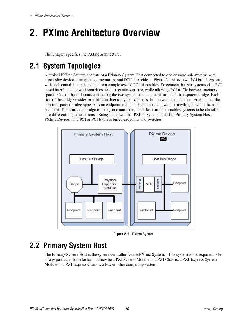
2.1 System TopologiesA typical PXImc System consists of a Primary System Host connected to one or more sub-systems with processing devices, independent memories, and PCI hierarchies. Figure 2-1 shows two PCI based systems with each containing independent root complexes and PCI hierarchies. To connect the two systems via a PCI based interface, the two hierarchies need to remain separate, while allowing PCI traffic between memory spaces. One of the endpoints connecting the two systems together contains a non-transparent bridge. Each side of this bridge resides in a different hierarchy, but can pass data between the domains. Each side of the non-transparent bridge appears as an endpoint and the other side is not aware of anything beyond the near endpoint. Therefore, the bridge is acting in a non-transparent fashion. This enables systems to be classified into different implementations. Subsystems within a PXImc System include a Primary System Host, PXImc Devices, and PCI or PCI Express based endpoints and switches.
Figure 2-1. PXImc System
2.2 Primary System HostThe Primary System Host is the system controller for the PXImc System. This system is not required to be of any particular form factor, but may be a PXI System Module in a PXI Chassis, a PXI-Express System Module in a PXI-Express Chassis, a PC, or other computing system.
PXI MultiComputing Hardware Specification Rev. 1.0 09/16/2009 10 www.pxisa.org
2 PXImc Architecture Overview
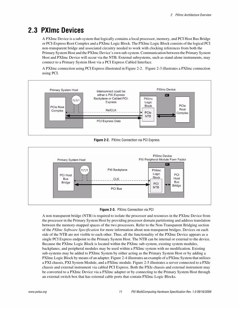
2.3 PXImc DevicesA PXImc Device is a sub-system that logically contains a local processor, memory, and PCI Host Bus Bridge or PCI-Express Root Complex and a PXImc Logic Block. The PXImc Logic Block consists of the logical PCI non-transparent bridge and associated circuitry needed to work with clocking references from both the Primary System Host and the PXImc Device’s own sub-system. Communication between the Primary System Host and PXImc Device will occur via the NTB. External subsystems, such as stand-alone instruments, may connect to a Primary System Host via a PCI Express Cabled Interface.
A PXImc connection using PCI Express illustrated in Figure 2-2. Figure 2-3 illustrates a PXImc connection using PCI.
Figure 2-2. PXImc Connection via PCI Express
Figure 2-3. PXImc Connection via PCI
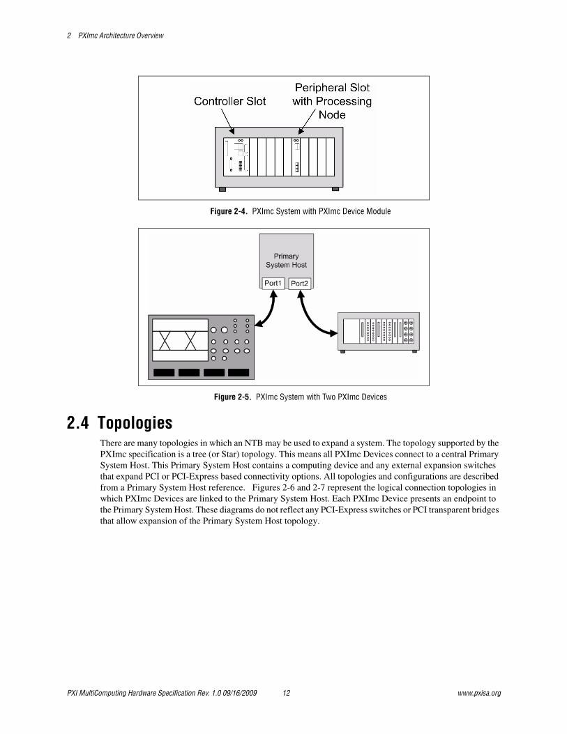
A non-transparent bridge (NTB) is required to isolate the processor and resources in the PXImc Device from the processor in the Primary System Host by providing processor domain partitioning and address translation between the memory-mapped spaces of the two processors. Refer to the Non-Transparent Bridging section of the PXImc Software Specification for more information about non-transparent bridges. Devices on each side of the NTB are not visible to each other. Thus, all the functionality of the PXImc Device appears as a single PCI Express endpoint to the Primary System Host. The NTB can be internal or external to the device. Because the PXImc Logic Block is located within the PXImc sub-system, existing system modules, backplanes, and peripheral modules may be used within a PXImc system with no modification. Existing sub-systems may be added to PXImc System by either acting as the Primary System Host or by adding a PXImc Logic Block by means of an adapter. Figure 2-4 illustrates an example of a PXImc System that utilizes a PXI chassis, PXI System Module, and a PXImc module. Figure 2-5 illustrates a server connected to a PXIe chassis and external instrument via cabled PCI Express. Both the PXIe chassis and external instrument may be converted to a PXImc Device via a PXImc adapter or by connecting to the Primary System Host through an external switch box that has external cable ports that contain PXImc Logic Blocks.
www.pxisa.org 11 PXI MultiComputing Hardware Specification Rev. 1.0 09/16/2009
2 PXImc Architecture Overview
Figure 2-4. PXImc System with PXImc Device Module
Figure 2-5. PXImc System with Two PXImc Devices
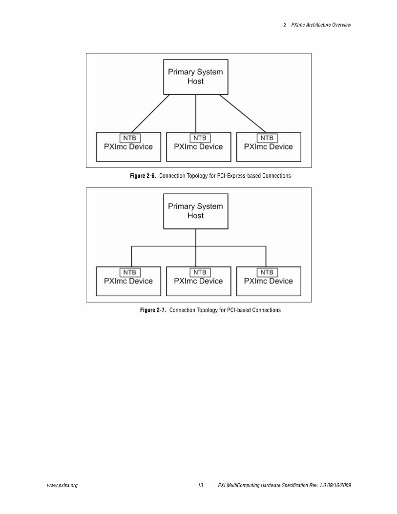
2.4 TopologiesThere are many topologies in which an NTB may be used to expand a system. The topology supported by the PXImc specification is a tree (or Star) topology. This means all PXImc Devices connect to a central Primary System Host. This Primary System Host contains a computing device and any external expansion switches that expand PCI or PCI-Express based connectivity options. All topologies and configurations are described from a Primary System Host reference. Figures 2-6 and 2-7 represent the logical connection topologies in which PXImc Devices are linked to the Primary System Host. Each PXImc Device presents an endpoint to the Primary System Host. These diagrams do not reflect any PCI-Express switches or PCI transparent bridges that allow expansion of the Primary System Host topology.
PXI MultiComputing Hardware Specification Rev. 1.0 09/16/2009 12 www.pxisa.org
2 PXImc Architecture Overview
Figure 2-6. Connection Topology for PCI-Express-based Connections
Figure 2-7. Connection Topology for PCI-based Connections
www.pxisa.org 13 PXI MultiComputing Hardware Specification Rev. 1.0 09/16/2009
2 PXImc Architecture Overview
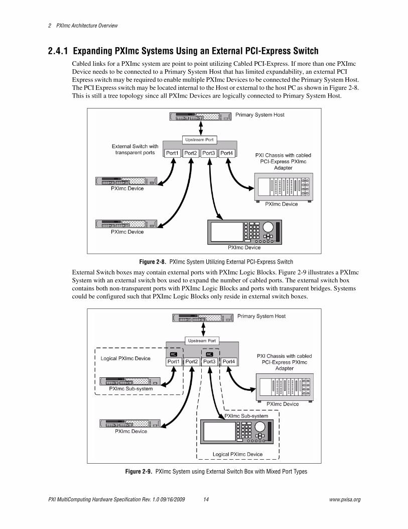
2.4.1 Expanding PXImc Systems Using an External PCI-Express SwitchCabled links for a PXImc system are point to point utilizing Cabled PCI-Express. If more than one PXImc Device needs to be connected to a Primary System Host that has limited expandability, an external PCI Express switch may be required to enable multiple PXImc Devices to be connected the Primary System Host. The PCI Express switch may be located internal to the Host or external to the host PC as shown in Figure 2-8. This is still a tree topology since all PXImc Devices are logically connected to Primary System Host.
Figure 2-8. PXImc System Utilizing External PCI-Express Switch
External Switch boxes may contain external ports with PXImc Logic Blocks. Figure 2-9 illustrates a PXImc System with an external switch box used to expand the number of cabled ports. The external switch box contains both non-transparent ports with PXImc Logic Blocks and ports with transparent bridges. Systems could be configured such that PXImc Logic Blocks only reside in external switch boxes.
Figure 2-9. PXImc System using External Switch Box with Mixed Port Types
PXI MultiComputing Hardware Specification Rev. 1.0 09/16/2009 14 www.pxisa.org
3 Electrical and Interface Requirements
3. Electrical and Interface Requirements
This chapter defines the electrical and interface requirements for PXImc Devices and Systems.
3.1 Electrical and Interface RequirementsThere are two fundamental types of modules for PXImc, the self-contained PXImc Device with the PXImc Logic Block and the local processing elements and the PXImc Adapter which enables an existing sub-system with available expansion option to be modified into a PXImc Device with the addition of the adapter.
RULE: A PXImc Device that is intended to be a PXI module SHALL comply with Peripheral Module requirements as defined by the PXI-1 specification.
RULE: A PXImc Device that is intended to be a PXI-Express module SHALL comply with Peripheral Module requirements as defined by the PXI-5 specification.
RULE: PXImc Adapters SHALL be compliant with the PCI Express External Cabling Specification.
PERMISSION: PXImc Adapters MAY be of any form factor, such as PXI Peripheral Module as defined by PXI-1 or PXI-Express Peripheral Module as defined by PXI-5.
PERMISSION: PXImc Adapters MAY be external to a sub-system. An example of this may be an external cable adapter that contains the PXImc Logic Block.
3.2 ClockingPCI and PCI-Express based components typically require common timing references for reliable operation. This section describes the specific rules for PXImc clocking.
RULE: The PXImc Logic Block SHALL use the clocking reference provided to both logical sides of the NTB.
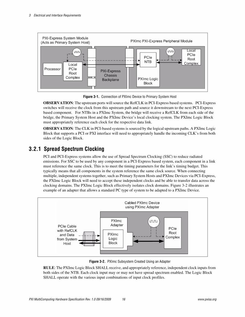
OBSERVATION: The Logic block may receive two separate PCI CLKs, two separate PCI-Express based RefCLKs, or a PCI CLK and a PCI-Express RefCLK. Figure 3-1 shows a clock diagram reference and how the PXImc Logic Block must interact with two incoming clocking references.
www.pxisa.org 15 PXI MultiComputing Hardware Specification Rev. 1.0 09/16/2009
3 Electrical and Interface Requirements
Figure 3-1. Connection of PXImc Device to Primary System Host
OBSERVATION: The upstream ports will source the RefCLK in PCI-Express based systems. PCI-Express switches will receive the clock from this upstream path and source it downstream to the next PCI-Express based component. For NTBs in a PXImc System, the bridge will receive a RefCLK from each side of the bridge, the Primary System Host and the PXImc Device’s local clocking system. The PXImc Logic Block must appropriately reference each clock for the respective data link.
OBSERVATION: The CLK in PCI-based systems is sourced by the logical upstream paths. A PXImc Logic Block that supports a PCI or PXI interface will need to appropriately handle the incoming CLK’s from both sides of the Logic Block.
3.2.1 Spread Spectrum ClockingPCI and PCI-Express systems allow the use of Spread Spectrum Clocking (SSC) to reduce radiated emissions. For SSC to be used by any component in a PCI-Express based system, each component in a link must reference the same clock. This is to meet the timing parameters for the link’s timing budget. This typically means that all components in the system reference the same clock source. When connecting multiple, independent systems together, such as Primary System Hosts and PXImc Devices via PCI-Express, the PXImc Logic Block will need to accept these independent clocks and be able to transfer data across the clocking domains. The PXImc Logic Block effectively isolates clock domains. Figure 3-2 illustrates an example of an adapter that allows a standard PC type of system to be adapted to a PXImc Device.
Figure 3-2. PXImc Subsystem Created Using an Adapter
RULE: The PXImc Logic Block SHALL receive, and appropriately reference, independent clock inputs from both sides of the NTB. Each clock input may or may not have spread spectrum enabled. The Logic Block SHALL operate with the various input combinations of input clock profiles.
PXI MultiComputing Hardware Specification Rev. 1.0 09/16/2009 16 www.pxisa.org
3 Electrical and Interface Requirements
OBSERVATION: The PCI Express Base Specification describes the specific behaviors of the spread spectrum clock modulation. Care should be taken to support clocks that adhere to these specifications. Some sub-systems may not have spread spectrum clocks, while others will. Combinations include two spread spectrum clock inputs, two non-spread spectrum clocks, and one spread and one non-spread spectrum clock.
OBSERVATION: Due to specific component behavior, some PXImc Logic Blocks may need to be manually configured, via hardware or software, to change between accepting incoming spread spectrum enabled clocks and non-spread spectrum clocks.
RECOMMENDATION: PXImc Peripheral Modules SHOULD use SSC enabled clocks for their local clocking reference to reduce peak radiated emissions.
OBSERVATION: This specification envisions the use of COTS hardware for PXImc Subsystems. These COTS systems will use typical motherboards with local clock generation with SSC enabled. The PXImc Device will need to appropriately use the independent reference clocks from the Primary System Host and the PXImc Device sub-system to allow for system operation.
OBSERVATION: Each clock domain transition incurs a latency penalty to cross clocking boundaries. This is inherent in systems with different operating frequencies.
OBSERVATION: Each component inserted between PCI-Express components increases complexity. Latency is increased and should be accounted for in the overall latency budgets, such as L0s or L1 exit latency and Retry Timer timeouts. PXImc subsystems should be designed to accommodate these latency increases that are greater than typical PCI-Express system configuration.
3.3 External Cabling ConnectorsRULE: External connectors SHALL comply with the PCI-Express External Cabling Specification connector definitions.
RECOMMENDATION: The standard cabled connection for PXImc Systems SHOULD be of the x4 link width.
RULE: PXImc Devices with external link widths larger than x4 SHALL be able to operate in a logical x4 link width configuration.
RULE: If the internal PCI-Express bus is x1, the x1 signals SHALL be routed to lane 0 of the external x4 cable connector if using a x4 connector.
PERMISSION: The x2 link MAY be used in a PXImc System.
RULE: If a x2 link is implemented, it SHALL use a x4 connector, aligning Lane 0 of the link with Lane 0 of the connector and Lane 1 of the link with Lane 1 of the connector.
OBSERVATION: Many components to not support the x2 link width, so a by x2 port may operate as a x1 when linked with another component.
RULE: Lane reversal, as defined by the PCI-Express Base Specification, SHALL NOT be used.
OBSERVATION: Lane reversal allows the reversing on individual lanes in a link. An example would be lanes 0 to N-1 of the upstream port being connected to lanes N-1 to 0 on the downstream port. PXImc may exhibit compatibility issues when a x2 link exists, or when a x8 or x16 link width port connector is mated to a x4 port connector via a cable. In either case, Lanes 0 will not be match to Lane N-1 of the mated link.
www.pxisa.org 17 PXI MultiComputing Hardware Specification Rev. 1.0 09/16/2009
3 Electrical and Interface Requirements
3.4 CablesRULE: Cables used for PXImc connections of link width x4 SHALL use the cable of link width x4 as defined by the PCI-Express External Cabling Specification.
RULE: Cables used for PXImc connections of link width x8 SHALL use the cable of link width x8 as defined by the PCI-Express External Cabling Specification.
RULE: Cables used for PXImc connections of link width x16 SHALL use the cable of link width x16 as defined by the PCI-Express External Cabling Specification.
RECOMMENDATION: PXImc Devices with link widths other than x4 SHOULD provide a mechanism to interface to a standard x4 board-side connector as defined by the PCI-Express External Cable Specification connector definition. This may require the use of a transition cable or adapter to reduce the cable from an x8 or x16 cable connector to a x4 cable connector or increase the width of a x1 cable connector to a x4 cable connector. Care should taken that all signaling requirements are met with the adapter is being used.
PERMISSION: If both cable ports of a link use the x1 connector, then a x1 cable MAY be used.
RULE: If both cable ports use the x1 connector, the connector SHALL comply with the External Cabled PCI Express Specification.
3.5 Hot-PlugRULE: PXImc Devices SHALL follow the rules for hot-plug support as specified by the form-factor specification for the module or adapter.
OBSERVATION: While the hardware may allow for hot-plugging, other components of the system may not. To ensure complete support for hot-plugging, all components must support this functionality, such as operating systems and applications.
3.6 System ResetRULE: All PXImc subsystems SHALL conform to the respective form factor specifications regarding the behavior and usage of the reset signals.
RULE: The reset signal SHALL not propagate through the NTB. Reset signals will only propagate through respective PCI hierarchies.
OBSERVATION: Since reset signals may not propagate through NTBs to the opposite endpoint, individual subsystems may be reset while other portions of the PXImc system will remain uninterrupted.
OBSERVATION: The Primary System Host may need to be reset if any of the PXImc Devices have been reset or removed.
3.7 Power SequencingOBSERVATION: There are no explicit power sequencing requirements for PXImc systems. PXImc Devices and all external switches in a cabled configuration must typically be powered before the Primary System Host for proper operation of the Primary System Host software. This ensures that the NTB endpoints for the Primary System Host will be powered and ready before the Primary System Host begins software configuration.
PXI MultiComputing Hardware Specification Rev. 1.0 09/16/2009 18 www.pxisa.org

3 Electrical and Interface Requirements
3.8 Environmental RequirementsDevices should conform to the respective form factor environmental requirements. Refer the either PXI-1 or PXI-5 Specifications for module requirements.
RULE: PXImc modules SHALL be tested for storage and operation temperature ranges.
RECOMMENDATION: Environmental ratings for PXImc products SHOULD be described in product datasheets.
www.pxisa.org 19 PXI MultiComputing Hardware Specification Rev. 1.0 09/16/2009
4 System Indicators
4. System Indicators
This section describes the rules and recommendations for indicators and markings used on PXImc products.
RULE: Vendors who are members of the PXI Systems Alliance SHALL use the PXImc Glyph on products claiming compliance with the PXImc specifications.
RULE: External cable ports of products that are compliant with the PXImc specifications SHALL have the PXImc Glyph to indicate each port that is intended for use as part of a PXImc Device.
OBSERVATION: Each labeled port will contain a PXImc Logic Block.
RULE: The location of the PXImc Glyph SHALL be in a position to leave no ambiguity as to which port or ports contain a PXImc Logic Block intended for PXImc Devices.
RULE: PXImc modules, or other form factors with no external ports, SHALL contain the PXImc Glyph in a location on the module that is visible to a user when the module is located in its operational location. An example might be a PXI PXImc processing module that will have the PXImc Glyph visible on the front panel when the module is seated into the PXI chassis.
RULE: The PXImc Glyph SHALL NOT be used to identify upstream cable ports that are intended to connect to the Primary System Host as a System Host expansion solution. Examples of an expansion solution would include an external switch box or an external chassis that allows additional modules of various form factors.
PERMISSION: Expansion solutions MAY be used to increase connectivity to the Primary System Host.
OBSERVATION: Expansion solutions allow additional endpoints or connectivity to the Primary System Host. These expansion solutions might contain PXImc Devices.
OBSERVATION: Some adapters may include both PXImc cable ports and transparent PCI-Express External Cable ports.
RULE: Vendors SHALL obtain a license to use the trademarked logo, referred to as the PXImc Glyph or glyph, and the glyph SHALL NOT altered in any way other than scale. The glyph SHALL NOT incorporate any additions.
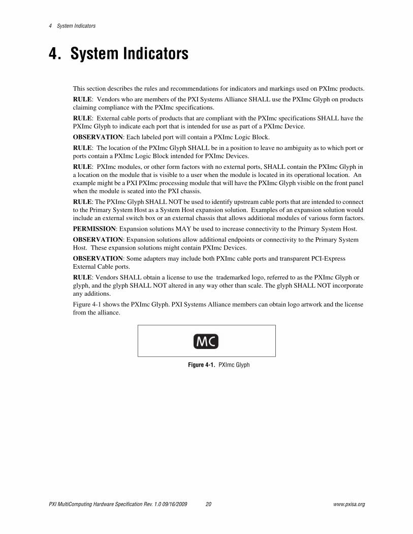
Figure 4-1 shows the PXImc Glyph. PXI Systems Alliance members can obtain logo artwork and the license from the alliance.
Figure 4-1. PXImc Glyph
PXI MultiComputing Hardware Specification Rev. 1.0 09/16/2009 20 www.pxisa.org
4 System Indicators
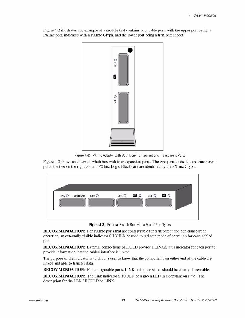
Figure 4-2 illustrates and example of a module that contains two cable ports with the upper port being a PXImc port, indicated with a PXImc Glyph, and the lower port being a transparent port.
Figure 4-2. PXImc Adapter with Both Non-Transparent and Transparent Ports
Figure 4-3 shows an external switch box with four expansion ports. The two ports to the left are transparent ports, the two on the right contain PXImc Logic Blocks are are identified by the PXImc Glyph.
Figure 4-3. External Switch Box with a Mix of Port Types
RECOMMENDATION: For PXImc ports that are configurable for transparent and non-transparent operation, an externally visible indicator SHOULD be used to indicate mode of operation for each cabled port.
RECOMMENDATION: External connections SHOULD provide a LINK/Status indicator for each port to provide information that the cabled interface is linked.
The purpose of the indicator is to allow a user to know that the components on either end of the cable are linked and able to transfer data.
RECOMMENDATION: For configurable ports, LINK and mode status should be clearly discernable.
RECOMMENDATION: The Link indicator SHOULD be a green LED in a constant on state. The description for the LED SHOULD be LINK.
www.pxisa.org 21 PXI MultiComputing Hardware Specification Rev. 1.0 09/16/2009

4 System Indicators
Figures 4-2 and 4-3 illustrate examples of what an external ports may look like that includes the LINK indicators.
RECOMMENDATION: An external switch box SHOULD clearly label the upstream port. An external switch box nominally contains two or more ports. One of these is an upstream port the connects the switch box to the Primary System Host. This upstream port label indicates to the user which port should be used to the switch to the logical path containing the root complex.
OBSERVATION: An indicator MAY additionally be a software indicator that the link is active. However, this may be less useful in a hardware debugging environment.
PXI MultiComputing Hardware Specification Rev. 1.0 09/16/2009 22 www.pxisa.org
5 Logo and Product Labeling
5. Logo and Product Labeling
PXImc Modules and Adapters may have the PXImc name and logo in their marketing material, datasheets, and manuals to help customers identify that the PXI products have the PXImc functionality.
RULE: References to the PXImc port in marketing literature or data sheets SHALL reference the port as the PXI MultiComputing port or the MutliComputing port defined by the PXI Systems Alliance.
PERMISSION: Vendors who are members of the PXI Systems Alliance MAY use the PXImc logo in the marketing material, datasheets, and manuals of PXImc PXI Modules, PXImc PXI-Express Modules, PXImc Adapters, or products with PXImc ports claiming full compliance with the PXI MultiComputing Specification.
Figure 5-1 illustrates the PXImc Logo. PXI Systems Alliance members can obtain logo artwork and the license from the alliance.
Figure 5-1. PXImc Logo
RULE: If the PXImc logo is used, the vendor SHALL obtain a license to use the trademarked logo from the PXI System Alliance.
RULE: If the PXImc logo is used, it SHALL NOT be altered in any way other than scale. The logo SHALL NOT incorporate any additions.
RULE: Vendors who are members of the PXI Systems Alliance SHALL NOT use the PXImc logo on any part of PXI or PXI Express hardware products.
www.pxisa.org 23 PXI MultiComputing Hardware Specification Rev. 1.0 09/16/2009