PX-xxxG5Le-72 Eng Spec V1.0(Advantech) 081913wfcache.advantech.com/www/certified-peripherals/... ·...
28
LITE-ON IT CORPORATION PX-xxxG5Le-72 Series 2.5" SATA Solid State Drive Engineering Specification (for Advantech) Version: 1.0 Status: Proposal Revision Date: 2013/08/19 Document No.: HSR027_13SSDX-005
Transcript of PX-xxxG5Le-72 Eng Spec V1.0(Advantech) 081913wfcache.advantech.com/www/certified-peripherals/... ·...

LITE-ON IT CORPORATION
PX-xxxG5Le-72 Series
2.5" SATA Solid State Drive
Engineering Specification
(for Advantech)
Version: 1.0
Status: Proposal
Revision Date: 2013/08/19
Document No.: HSR027_13SSDX-005
Page 2 of 28 Prodcut Specification
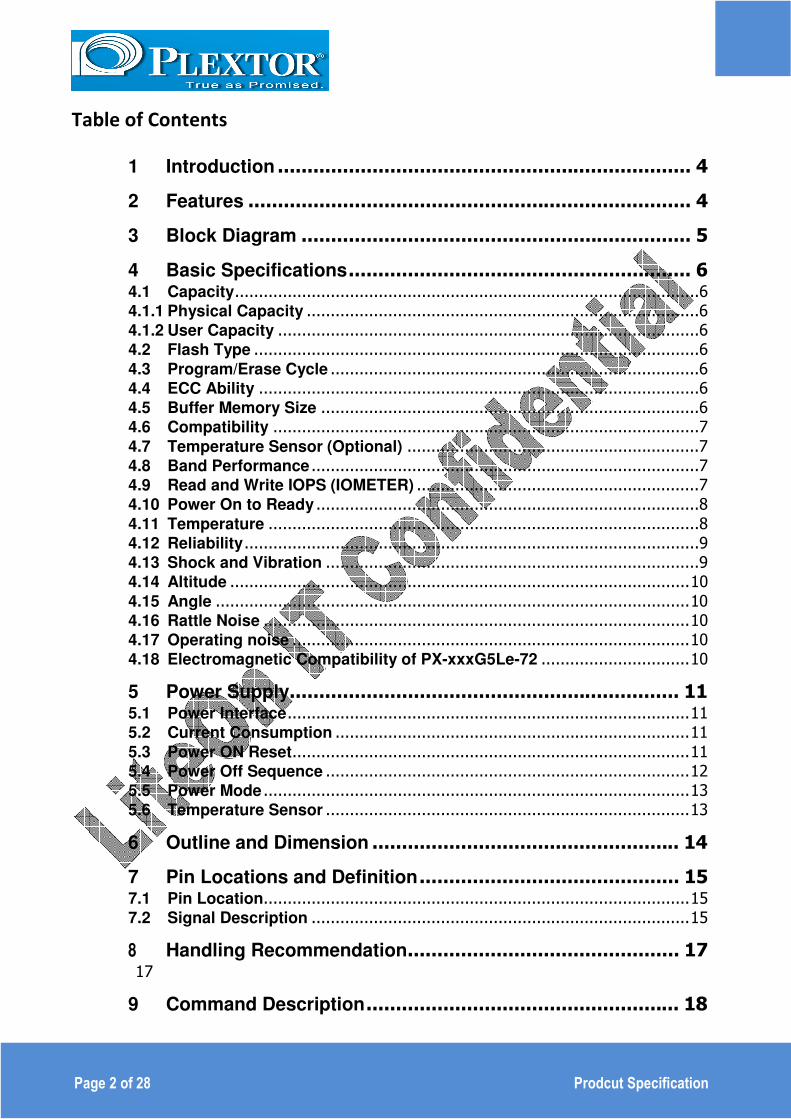
Table of Contents
1 Introduction ...................................................................... 4
2 Features ........................................................................... 4
3 Block Diagram .................................................................. 5
4 Basic Specifications .......................................................... 6
4.1 Capacity .................................................................................................6
4.1.1 Physical Capacity ..................................................................................6
4.1.2 User Capacity ........................................................................................6
4.2 Flash Type .............................................................................................6
4.3 Program/Erase Cycle .............................................................................6
4.4 ECC Ability ............................................................................................6
4.5 Buffer Memory Size ...............................................................................6
4.6 Compatibility .........................................................................................7
4.7 Temperature Sensor (Optional) .............................................................7
4.8 Band Performance .................................................................................7
4.9 Read and Write IOPS (IOMETER) ...........................................................7
4.10 Power On to Ready ................................................................................8
4.11 Temperature ..........................................................................................8
4.12 Reliability ...............................................................................................9
4.13 Shock and Vibration ..............................................................................9
4.14 Altitude ................................................................................................ 10
4.15 Angle ................................................................................................... 10
4.16 Rattle Noise ......................................................................................... 10
4.17 Operating noise ................................................................................... 10
4.18 Electromagnetic Compatibility of PX-xxxG5Le-72 ............................... 10
5 Power Supply .................................................................. 11
5.1 Power Interface .................................................................................... 11
5.2 Current Consumption .......................................................................... 11
5.3 Power ON Reset ................................................................................... 11
5.4 Power Off Sequence ............................................................................ 12
5.5 Power Mode ......................................................................................... 13
5.6 Temperature Sensor ............................................................................ 13
6 Outline and Dimension .................................................... 14
7 Pin Locations and Definition ............................................ 15
7.1 Pin Location ......................................................................................... 15
7.2 Signal Description ............................................................................... 15
8 Handling Recommendation .............................................. 17
17
9 Command Description ..................................................... 18

Page 3 of 28 Prodcut Specification
9.1 ATA Command .................................................................................... 18
9.2 Vendor Specify Command: Get Temperature Command (Optional) .... 21
9.3 Identify Device Data ............................................................................. 22
References.............................................................................. 27
Terms and Acronyms ................................................................ 28
Table 1 User Addressable Sectors ............................................................................... 6
Table 2 Maximum Sustained Read and Write Bandwidth ...................................... 7
Table 3 Random Read/Write Input/output Operations per Second ..................... 7
Table 4 Latency Specifications ...................................................................................... 8
Table 5 Temperature Relative Specifications ............................................................ 8
Table 6 Reliability specifications .................................................................................. 9
Table 7 Shock and Vibration .......................................................................................... 9
Table 8 Radio Frequency Specifications .................................................................. 10
Table 10 Operating Voltage .......................................................................................... 11
Table 11 Current Consumption .................................................................................... 11
Table 12 Power On Reset Characteristics ................................................................ 11
Table 13 DC Characteristics ......................................................................................... 13
Table 14 Pin Name........................................................................................................... 15
Figure 1 Block Diagram .......................................................................................................... 5
Figure 2 Buffer Memory ......................................................................................................... 6
Figure 3 Power On Reset ...................................................................................................... 12
Figure 4 Power off sequence ............................................................................................... 12
Figure 5 Power Mode ........................................................................................................... 13
Page 4 of 28 Prodcut Specification
1 Introduction
The PX-xxxG5Le-72 2.5" SATA Solid State Drive (SSD) deliver leading performance in an industry
standard 2.5" form factor while simultaneously improving system responsiveness over standard rotating
drive media or hard disk drives. By combining leading NAND flash memory technology with our innovative
high performance firmware; LITE-ON IT delivers 2.5” SATA SSD drives drop-in replacement with
enhanced performance, reliability, ruggedness and power savings. Since there are no rotating platters,
moving heads, fragile actuators, or unnecessary delays due to spin-up time or positional seek time that
can slow down the storage subsystem, significant I/O and throughput performance improvement is
achieved as compared to rotating media or hard disk drives. This document describes the specifications
of the PX-xxxG5Le-72 2.5" SATA Solid State Drive (SSD) form factors.
The PX-xxxG5Le-72 2.5" SATA SSD key attributes include high performance, low power, increased
system responsiveness, high reliability, and enhanced ruggedness as compared to standard SATA hard
drives. The PX-xxxG5Le-72 2.5" SATA SSD is available in a 2.5" form factor that is electrically,
mechanically, and software compatible with existing 2.5” SATA slots and cables. Our flexible design
allows interchangeability with existing mobile hard drives based on the SATA interface standard.
2 Features
� High speed mass storage device
� S-ATA III 6.0G interface
� No movement parts and noise free
� Excellent ability against Shock/Vibration
� Fast access performance
� Temperature detection
� Form Factor:
2.5” SSD form factor
Page 5 of 28 Prodcut Specification
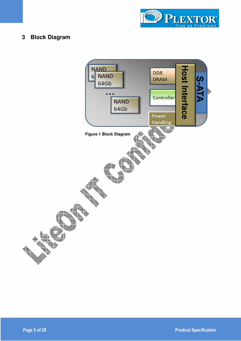
3 Block Diagram
Figure 1 Block Diagram
Ho
st In
terfa
ce

Page 6 of 28 Prodcut Specification
4 Basic Specifications
4.0 Key Component and FW Version
4.0.1 Flash Type: Toshiba 19nm
4.0.2 Controller: Marvell Monet Lite 9188
4.0.3 FW Version: FW Version:1.02
4.1 Capacity
4.1.1 Physical Capacity
32GB, PX-32G5Le-72
64GB, PX-64G5Le-72
4.1.2 User Capacity
Unformatted capacity Total user addressable
sectors in LBA mode
32GB 62,533,296
64GB 125,045,424
Table 1 User Addressable Sectors
Notes: 1. 1GB=1,000,000,000 bytes and not all of the memory can be used for storage.
2. 1 Sector = 512 bytes
4.2 Flash Type
Multi-Level Cell (MLC), Program/Erase Cycle
3000(global)
4.3 ECC Ability
81bits/2KB
4.4 Buffer Memory Size
128MB DDR3, consist of FTL Table and write cache data.
Figure 2 Buffer Memory
FTL Table
Write Cache Data

Page 7 of 28 Prodcut Specification
4.5 Compatibility
-- SATA Revision 3.0 compliant
Compatible with SATA 1.5Gb/s, 3.0Gb/s & 6.0Gb/s Interface rates
-- ATA/ATAPI- 8 compliant
-- SSD enhanced SMART ATA feature set
-- Native Command Queuing (NCQ) command set
-- TRIM supported
4.6 Temperature Sensor (Optional)
The temperature information is available from a built-in temperature sensor between -40 °C to
+125 °C with ± 3 °C accuracy.
4.7 Band Performance
Capacity Access Type MB/s
32GB Sequential Read Up to 360 MB/s
Sequential Write Up to 80 MB/s
64GB Sequential Read Up to 360 MB/s
Sequential Wrire Up to 160 MB/s
Table 2 Maximum Sustained Read and Write Bandwidth
Notes: 1). Performance measured using CrystalDiskMark.
2). 1 MB/sec = 1,048,576 bytes/sec is used in measuring sequential performance.
If 1 MB/sec = 1,000,000 bytes/sec is used, performance values become 4.85% higher.
4.8 Read and Write IOPS (IOMETER)
Capacity Access Type IOPS
32 GB
4K Read (IOPS) 40,000
4K Write (IOPS) 20,000
64 GB
4K Read (IOPS) 40,000
4K Write (IOPS) 40,000
Table 3 Random Read/Write Input/output Operations per Second
Notes: 1. Performance measured using IOMETER with queue depth set to 1.
2. Write cache enabled

Page 8 of 28 Prodcut Specification
4.9 Power On to Ready
Operating Mode Typical (25°C) Max.(0°C to +70°C)
Power on to Ready 1s 4s
Table 4 Latency Specifications
Notes: 1. Write cache enabled
2. Device measured using Drive Master
3. Power on to ready time assumes proper shutdown
(Power removal preceded by Flush Cache or STANDBY command)
4.10 Temperature
Environment Mode Min Max Unit
Ambient
Temperature
Operating 0 70 °C
Non-operating,
Storage
-40 90 °C
Humidity
Operation 5 95 %
Non-operation,
Storage 5 95 %
Thermal
Gradient
Operation,
Non-operation,
Storage
5 -
°C/ min
Table 5 Temperature Relative Specifications

Page 9 of 28 Prodcut Specification
4.11 Reliability
Parameter Value
Mean Time between Failure
(MTBF) 1,500,000 Hours
Power on/off cycles 25,000 cycles
Data Reliability 1 per 1013
bits read (max)
Interface 50 cycles of Insert and Removal
operation(min)
Table 6 Reliability specifications
Notes:
1. MTBF is calculated based on a Part Stress Analysis. It assumes nominal voltage.
With all other parameters within specified range.
2. Power on/off cycles is defined as power being removed from the drive, and the
restored. Application systems remove power with the Flush Cache command or
Standby Immediate command in advance before the system shutdown.
4.12 Shock and Vibration
Item Mode Timing/Frequency Max
Shock1
Operation
Non-operating At 1 msec half-sine
1500G
Operation
Non-operating At 2 msec half-sine
1000G
Random
Vibration2
Operation 7~800 Hz 2.17Grms
Non-operation 7~800 Hz 3.08Grms
Table 7 Shock and Vibration
Notes:
1. Shock specifications assume that the SSD is mounted securely with the input
vibration applied to the drive mounting screws. Stimulus may be applied in the X, Y
or Z axis
2. Vibration specifications assume that the SSD is mounted securely with the input
vibration applied to the drive mounting screws. Stimulus may be applied in the X, Y
or Z axis. The measured specification is in root mean squared form.

Page 10 of 28 Prodcut Specification
4.13 Altitude
Operational Altitude: 5,500 meters
Altitude Gradient: 300m / min
4.14 Angle
The drives will operate at any Angle or/and Orientation.
4.15 Rattle Noise
The drives will have no rattle noise during any operation.
Note: There are no movement parts in the SSD drives; the rattle noise will not be tested.
4.16 Operating noise
The operating noise of the module will not exceed 35dBA (20Hz to 20kHz)
Note: There are no movement parts in the SSD drive; the operation noise will not be tested.
4.17 Electromagnetic Compatibility of PX-xxxG5Le-72
Electromagnetic compatibility tests assume the SSD is properly installed in the representative host
system. The drive operates properly without errors degradation in performance when subjected to
radio frequency (RF) environments defined in the following table.
Test Description Performance
criteria Reference standard
Electrostatic discharge Packaging and Handling
Contact ±4KV ±8KV
A IEC 61000-4-2:2008
Electrostatic discharge Production and Service
Contact ±2KV A IEC 61000-4-2:2008
Radiated Emission - - CISPER-22 Class B
Table 8 Radio Frequency Specifications
Notes: 1. Performance criterion A = The device shall continue to operate as intended, i.e.,
normal unit operation with no degradation of performance.
2. Performance criterion B = The device shall continue to operate as intended after completion of test, however, during the test, some degradation of performance is allowed as long as there is no data loss operator intervention to restore device function.
3. Performance criterion C = Temporary loss of function is allowed. Operator intervention is acceptable to restore device function.
4. Contact electrostatic discharge is applied to drive enclosure during operation.
5. Contact electrostatic discharge is applied to drive enclosure and I/O pins when Non-Operation.
Page 11 of 28 Prodcut Specification
5 Power Supply
5.1 Power Interface
Description Specifications
Nominal Supply (V1) +5Vdc +/- 5%
Absolute Voltage Min. -0.5V
Max. +10V
Ripple voltage
(0-20MHz) 150mV p-p max
Supply Rise Time 1 – 100ms
Table 9 Operating Voltage
5.2 Current Consumption
PX-64G5Le-72@ 5V
Operation Mode Typical Max. Unit
Read Mode 0.37 0.5 A
Write Mode 0.42 0.55 A
Standby 0.025 0.04 A
Sleep 0.025 0.04 A
Power On Inrush Current - 1.0 (T<10ms) A
Table 10 Current Consumption
Note: Active power is measured using IOMETER Power Consumption with RMS current 5s.
Active Mode: Measured after power on initiation and without activity.
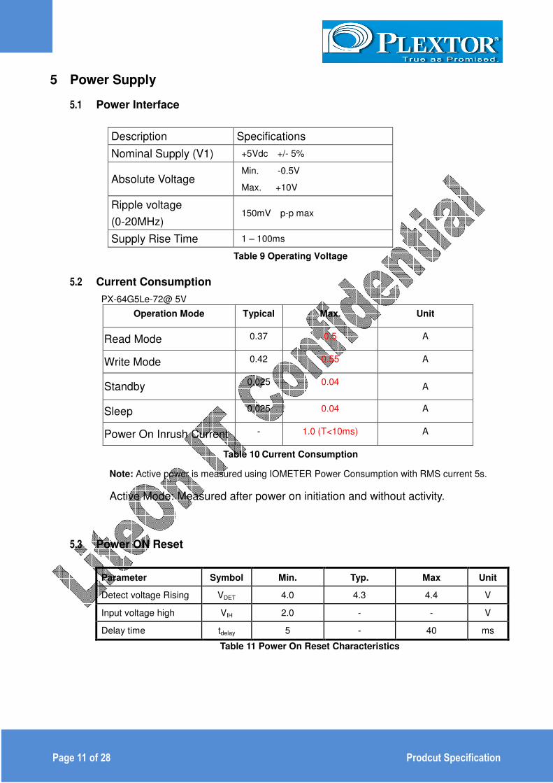
5.3 Power ON Reset
Parameter Symbol Min. Typ. Max Unit
Detect voltage Rising VDET 4.0 4.3 4.4 V
Input voltage high VIH 2.0 - - V
Delay time tdelay 5 - 40 ms
Table 11 Power On Reset Characteristics
Page 12 of 28 Prodcut Specification
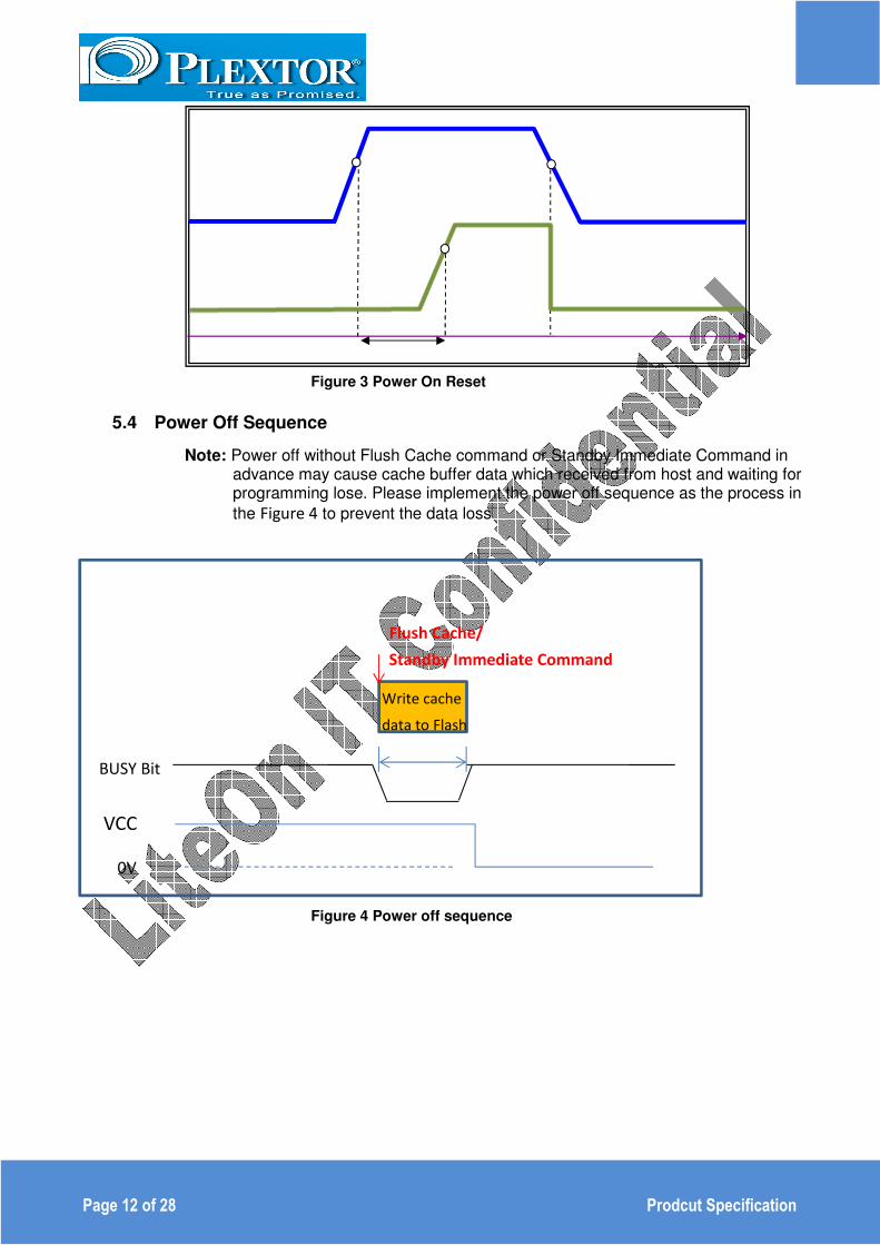
Figure 3 Power On Reset
5.4 Power Off Sequence
Note: Power off without Flush Cache command or Standby Immediate Command in advance may cause cache buffer data which received from host and waiting for programming lose. Please implement the power off sequence as the process in
the Figure 4 to prevent the data loss
Figure 4 Power off sequence
VCC
0V
Write cache
data to Flash
Flush Cache/
Standby Immediate Command
BUSY Bit

Page 13 of 28 Prodcut Specification
5.5 Power Mode
Figure 5 Power Mode
The module has a reset controlled protection implemented.
5.6 Temperature Sensor
Parameter Symbol Min. Typ. Max Unit
Temperature range - -40 - +125 ℃
Resolution VIL - - 0.25 ℃
Temperature error
-40~+125℃ TERROR1 - - ±3 ℃
Temperature error
-25~+85℃ TERROR2 - - ±2 ℃
Table 12 DC Characteristics
0V
-1V
10V
Behavior
States V.S. voltage
4.3V Full specification
Internal Reset

Page 14 of 28 Prodcut Specification
6 Outline and Dimension
6.1 The module is compliance to SFF-8201 6.2 Dimension: 100.0mm x 69.85mm x 6.8 mm (L x W x H) 6.3 Weight: 60 g Max (with case ) 6.4 The module is capable of taking maximum tightening screw torque of 0.4 Nm
6.5 The module is fully functional when subject to Flatness or Co-planarity of 0.5 mm
Page 15 of 28 Prodcut Specification
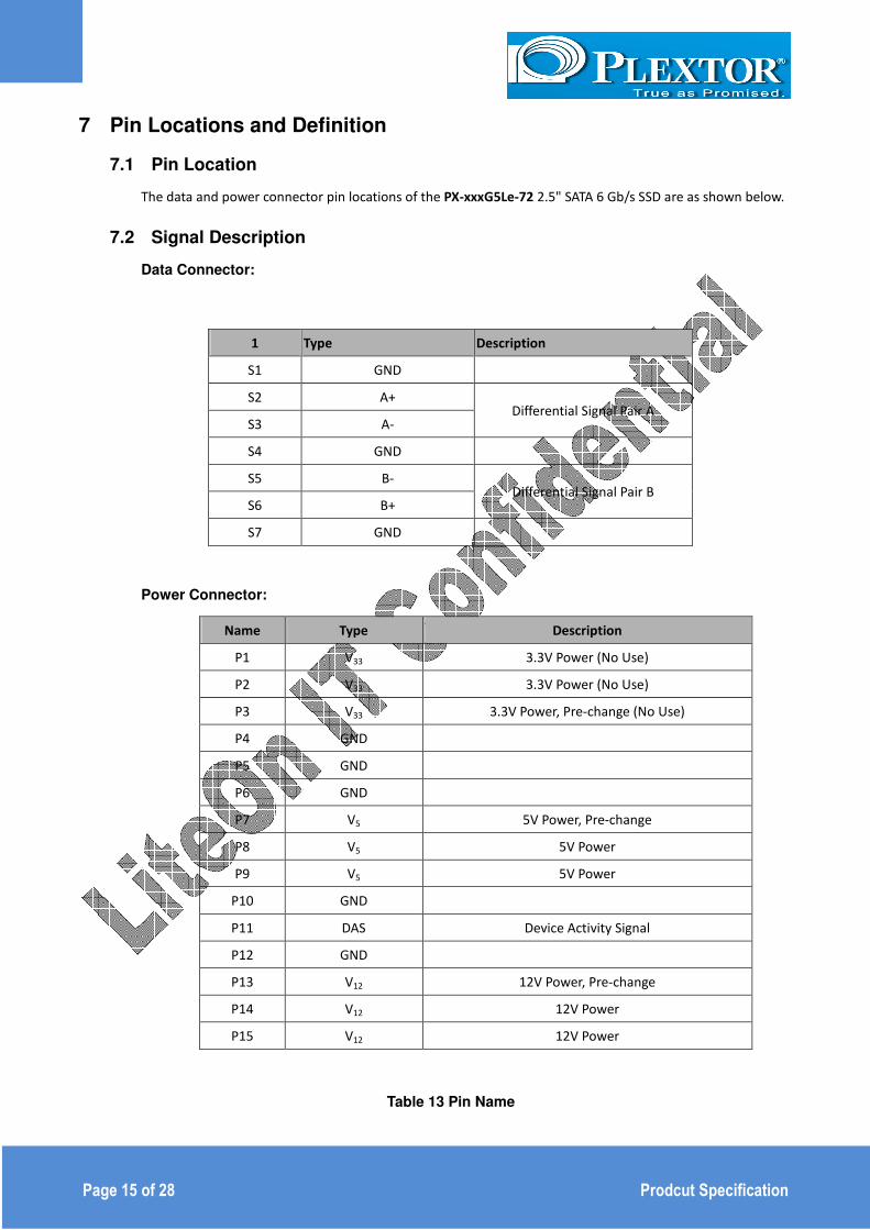
7 Pin Locations and Definition
7.1 Pin Location
The data and power connector pin locations of the PX-xxxG5Le-72 2.5" SATA 6 Gb/s SSD are as shown below.
7.2 Signal Description
Data Connector:
1 Type Description
S1 GND
S2 A+ Differential Signal Pair A
S3 A-
S4 GND
S5 B- Differential Signal Pair B
S6 B+
S7 GND
Power Connector:
Name Type Description
P1 V33 3.3V Power (No Use)
P2 V33 3.3V Power (No Use)
P3 V33 3.3V Power, Pre-change (No Use)
P4 GND
P5 GND
P6 GND
P7 V5 5V Power, Pre-change
P8 V5 5V Power
P9 V5 5V Power
P10 GND
P11 DAS Device Activity Signal
P12 GND
P13 V12 12V Power, Pre-change
P14 V12 12V Power
P15 V12 12V Power
Table 13 Pin Name

Page 16 of 28 Prodcut Specification
Note:
1. All pins are in a single row, with a 1.27mm (0.05”) pitch
2. Pins P1, P2 and P3 are connected together, although they are not connected internally to the
device. The host may put 3.3v on these pins.
3. The mating sequence is
- The ground pins P4-P6, P10, P12 and the 5V power pin P7
- The signal pins and the rest of the 5V power pins P8-P9
4. Ground connectors P4 and P12 may contact before the other 1st mate pins in both the power
and signal connectors to discharge ESD in a suitably configured backplane connector.
5. Power pins P7, P8 and P9 are internally connected to one another within the device.
6. The host may ground P11 if it is not used for Device Activity Signal (DAS)
7. Pins P13, P14, P15 are connected together, although they are not connected internally to the
device.
Page 17 of 28 Prodcut Specification
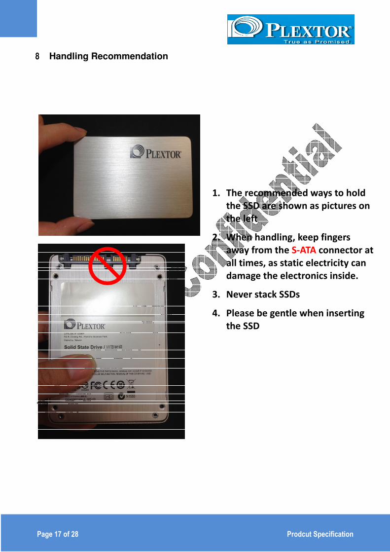
8 Handling Recommendation
1. The recommended ways to hold
the SSD are shown as pictures on
the left
2. When handling, keep fingers
away from the S-ATA connector at
all times, as static electricity can
damage the electronics inside.
3. Never stack SSDs
4. Please be gentle when inserting
the SSD

Page 18 of 28 Prodcut Specification
9 Command Description
9.1 ATA Command
The PX-xxxG5Le-72 2.5" SATA SSD support all the mandatory ATA commands defined in the
ATA/ATAPI-8 specification.
ATA General Feature Command Set
General feature Command set (non-packet)
.EXECUTE DEVICE DIAGNOSTIC .FLUSH CACHE .IDENTIFY DEVICE .READ DMA .READ SECTOR(S) .READ VERIFY SECTORS(S) .SEEK .SET FEATURES .TRIM (*ATA/ATAPI-8 specification) .WRITE DMA .WRITE SECTOR(S) .READ MULTIPLE .SET MULTIPLE MODE .WRITE MULTIPLE
Optional commands .READ BUFFER .WRITE BUFFER .NOP .DOWNLOAD MICROCODE
Power Management Command Set .CHECK POWER MODE .IDLE .IDLE IMMEDIATE .SLEEP .STANDBY .STANDBY IMMEDIATE

Page 19 of 28 Prodcut Specification
Security Mode Feature Set .SECURITY SET PASSWORD .SECURITY UNLOCK .SECURITY ERASE PREPARE .SECURITY ERASE UNIT .SECURITY FREEZE LOCK .SECURITY DISABLE PASSWORD
Host Protected Area Command Set .READ NATIVE MAX ADDRESS .SET MAX ADDRESS .READ NATIVE MAX ADDRESS EXT .SET MAX ADDRESS EXT
Optional commands. .SET MAX SET PASSWORD .SET MAX LOCK .SET MAX FREEZE LOCK .SET MAX UNLOCK
48-Bit Address Command Set .READ NATIVE MAX ADDRESS .FLUSH CACHE EXT .READ DMA EXT .READ NATIVE MAX ADDRESS EXT .READ SECTOR(S) EXT .READ VERIFY SECTOR(S) EXT .SET MAX ADDRESS EXT .WRITE DMA EXT .WRITE MULTIPLE EXT .WRITE SECTOR(S) EXT
SMART Command Set .SMART ENABLE OPERATIONS .SMART DISABLE OPERATIONS .SMART ENABLE/DISABLE AUTOSAVE .SMART RETURN STATUS

Page 20 of 28 Prodcut Specification
Optional commands. .SMART EXECUTE OFF-LINE IMMEDIATE .SMART READ DATA .SMART READ LOG .SMART WRITE LOG
The table below lists the SMART commands.
Subcommand Code LBA Low
value
SMART ATTRIBUTE VALUES (READ DATA) D0h
READ ATTRIBUTE THRESHOLDS D1h
ENABLE/DISABLE ATTRIBUTE AUTOSAVE D2h
SAVE ATTRIBUTE VALUES D3h
EXECUTE OFF-LINE IMMEDIATE D4h
EXECUTE SMART OFF-LINE ROUTINE 00h
EXECUTE SMART SHORT SELF-TEST ROUTINE
(OFFLINE)
01h
EXECUTE SMART EXTENDED SELF-TEST ROUTINE
(OFFLINE)
02h
ABORT OFF-LINE ROUTINE 7Fh
EXECUTE SMART SHORT SELF-TEST ROUTINE
(CAPTIVE)
81h
EXECUTE SMART EXTENDED SELF-TEST ROUTINE
( CAPTIVE )
82h
READ LOG SECTOR D5h
WRITE LOG SECTOR D6h
ENABLE SMART OPERATIONS D8h
DISABLE SMART OPERATIONS D9h
RETURN SMART STATUS DAh
Enable/Disable Automatic OFFLINE DBh
Page 21 of 28 Prodcut Specification
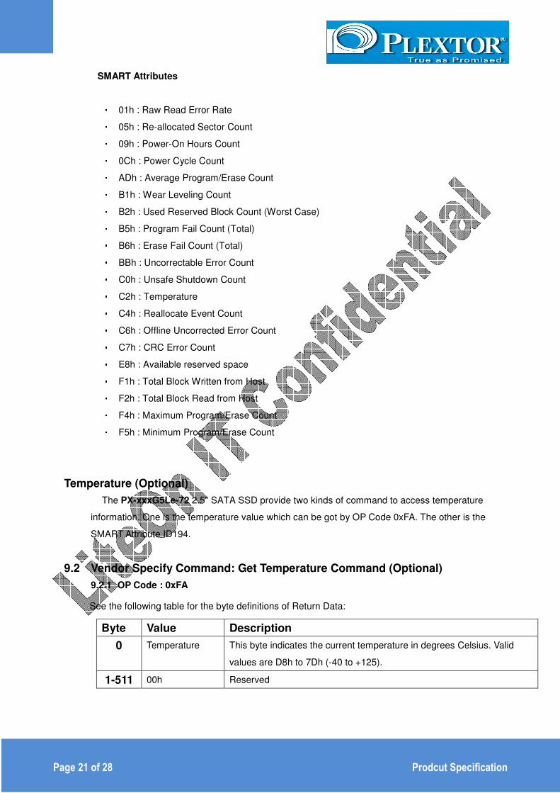
SMART Attributes
• 01h : Raw Read Error Rate • 05h : Re-allocated Sector Count • 09h : Power-On Hours Count • 0Ch : Power Cycle Count • ADh : Average Program/Erase Count • B1h : Wear Leveling Count • B2h : Used Reserved Block Count (Worst Case) • B5h : Program Fail Count (Total) • B6h : Erase Fail Count (Total) • BBh : Uncorrectable Error Count • C0h : Unsafe Shutdown Count • C2h : Temperature • C4h : Reallocate Event Count • C6h : Offline Uncorrected Error Count • C7h : CRC Error Count • E8h : Available reserved space • F1h : Total Block Written from Host • F2h : Total Block Read from Host • F4h : Maximum Program/Erase Count • F5h : Minimum Program/Erase Count
Temperature (Optional)
The PX-xxxG5Le-72 2.5" SATA SSD provide two kinds of command to access temperature
information. One is the temperature value which can be got by OP Code 0xFA. The other is the
SMART Attribute ID194.
9.2 Vendor Specify Command: Get Temperature Command (Optional)
9.2.1 OP Code : 0xFA
See the following table for the byte definitions of Return Data:
Byte Value Description
0 Temperature This byte indicates the current temperature in degrees Celsius. Valid
values are D8h to 7Dh (-40 to +125).
1-511 00h Reserved

Page 22 of 28 Prodcut Specification
9.2.2 SMART Attribute C2h
Attribute ID: C2h (194 decimal)
Threshold: None
Description: The Temperature attribute indicates the current drive temperature in degrees
Celsius.
See the following table for the byte definitions.
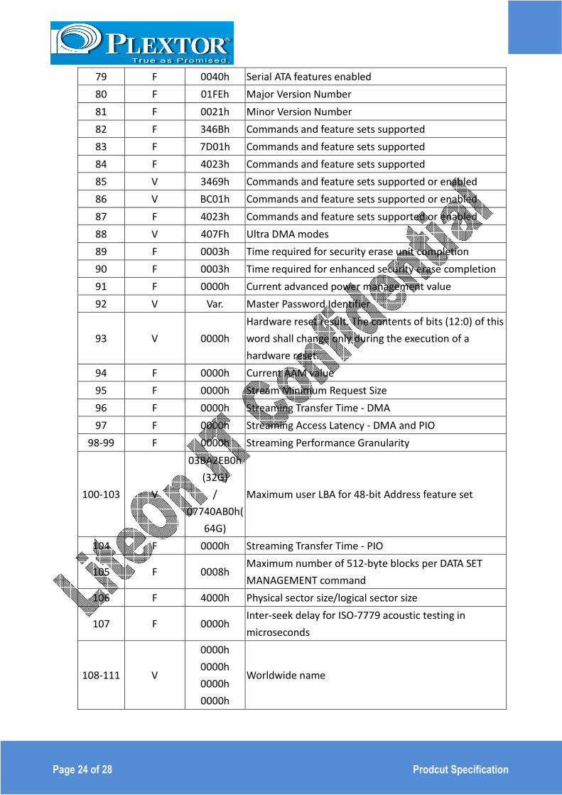
9.3 Identify Device Data
The following table details the sector data returned after issuing an IDENTIFY DEVICE command.
Word
F=Fixed
V=Variable
X=Both
Default
Value Description
0 F 0040h General configuration bit-significant information
1 F 3FFFh Obsolete-Number of logical cylinders (16,383)
2 F C837h Specific configuration
3 F 0010h Obsolete-Number of logical heads (16)
4-5 F 0000h Retired
6 F 003Fh Obsolete-Number of logical sectors per logical track (63)
7-8 F 0000h Reserved for assignment by the Compact Flash
Association
9 F 0000h Retired
10-19 V Var. Serial number (20 ASCII characters)
20-22 F 0000h Retired / Obsolete
Byte Value Description
0 C2h This is the attribute ID (194 decimal).
1-2 00h Set to 0200h to indicate the attribute does not trigger an
imminent failure (that is, the pre-fail advisory bit is not set).
3 64h Each of these bytes is set to a constant value, which is
always
64h (100 decimal).
4 64h
5 As description This byte indicates the current temperature in degrees
Celsius.
Valid values are D8h to 7Dh (-40 to +125).
6-11 00h Reserved
Page 23 of 28 Prodcut Specification
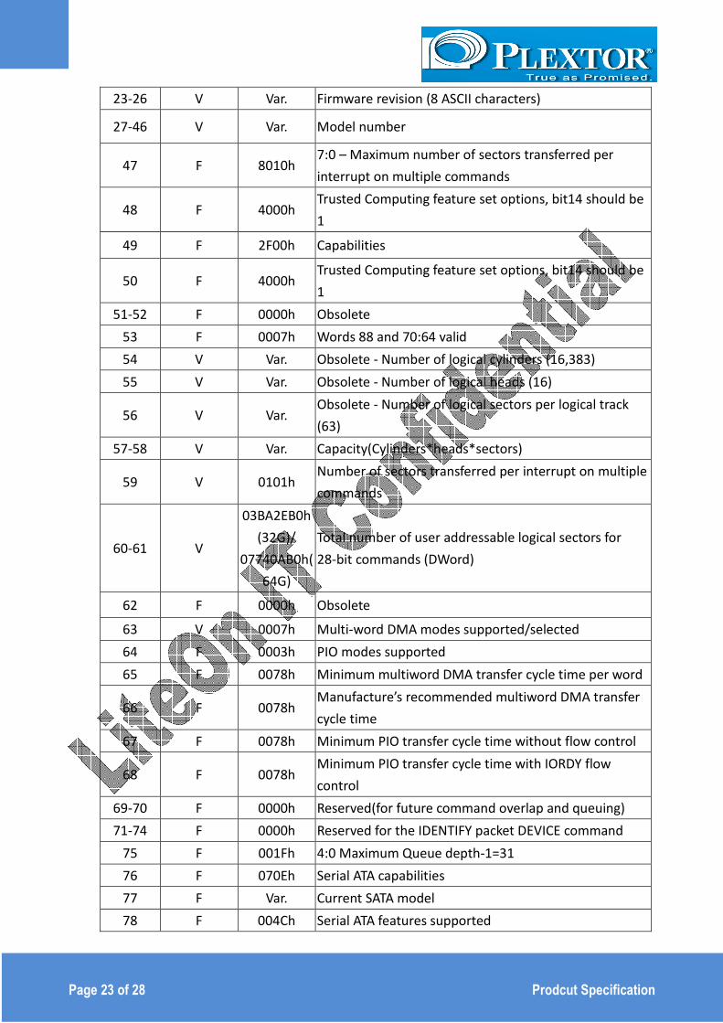
23-26 V Var. Firmware revision (8 ASCII characters)
27-46 V Var. Model number
47 F 8010h 7:0 – Maximum number of sectors transferred per
interrupt on multiple commands
48 F 4000h Trusted Computing feature set options, bit14 should be
1
49 F 2F00h Capabilities
50 F 4000h Trusted Computing feature set options, bit14 should be
1
51-52 F 0000h Obsolete
53 F 0007h Words 88 and 70:64 valid
54 V Var. Obsolete - Number of logical cylinders (16,383)
55 V Var. Obsolete - Number of logical heads (16)
56 V Var. Obsolete - Number of logical sectors per logical track
(63)
57-58 V Var. Capacity(Cylinders*heads*sectors)
59 V 0101h Number of sectors transferred per interrupt on multiple
commands
60-61 V
03BA2EB0h
(32G)/
07740AB0h(
64G)
Total number of user addressable logical sectors for
28-bit commands (DWord)
62 F 0000h Obsolete
63 V 0007h Multi-word DMA modes supported/selected
64 F 0003h PIO modes supported
65 F 0078h Minimum multiword DMA transfer cycle time per word
66 F 0078h Manufacture’s recommended multiword DMA transfer
cycle time
67 F 0078h Minimum PIO transfer cycle time without flow control
68 F 0078h Minimum PIO transfer cycle time with IORDY flow
control
69-70 F 0000h Reserved(for future command overlap and queuing)
71-74 F 0000h Reserved for the IDENTIFY packet DEVICE command
75 F 001Fh 4:0 Maximum Queue depth-1=31
76 F 070Eh Serial ATA capabilities
77 F Var. Current SATA model
78 F 004Ch Serial ATA features supported
Page 24 of 28 Prodcut Specification
79 F 0040h Serial ATA features enabled
80 F 01FEh Major Version Number
81 F 0021h Minor Version Number
82 F 346Bh Commands and feature sets supported
83 F 7D01h Commands and feature sets supported
84 F 4023h Commands and feature sets supported
85 V 3469h Commands and feature sets supported or enabled
86 V BC01h Commands and feature sets supported or enabled
87 F 4023h Commands and feature sets supported or enabled
88 V 407Fh Ultra DMA modes
89 F 0003h Time required for security erase unit completion
90 F 0003h Time required for enhanced security erase completion
91 F 0000h Current advanced power management value
92 V Var. Master Password Identifier
93 V 0000h
Hardware reset result. The contents of bits (12:0) of this
word shall change only during the execution of a
hardware reset.
94 F 0000h Current AAM value
95 F 0000h Stream Minimum Request Size
96 F 0000h Streaming Transfer Time - DMA
97 F 0000h Streaming Access Latency - DMA and PIO
98-99 F 0000h Streaming Performance Granularity
100-103 V
03BA2EB0h
(32G)
/
07740AB0h(
64G)
Maximum user LBA for 48-bit Address feature set
104 F 0000h Streaming Transfer Time - PIO
105 F 0008h Maximum number of 512-byte blocks per DATA SET
MANAGEMENT command
106 F 4000h Physical sector size/logical sector size
107 F 0000h Inter-seek delay for ISO-7779 acoustic testing in
microseconds
108-111 V
0000h
0000h
0000h
0000h
Worldwide name

Page 25 of 28 Prodcut Specification
112-115 F 0000h Reserved for word wide name extension to 128 bits
116 F 0000h Reserved for TLC
117-118 F 0000h Words per logical sector
119 F 4010h Commands and feature sets supported
120 F 4010h Commands and feature sets supported or enabled
121-126 F 0000h Reserved for expanded supported and enabled settings
127 F 0000h Removable Media Status Notification feature set
support
128 V 0021h Security status
129-159 F 0000h Vendor specific
160 F 0000h Compact Flash Association (CFA) power mode 1
161-167 F 0000h Reserved for the CompactFlash Association
168 F 0000h
169 F 0001h DATA SET MANAGEMENT command is supported
170-173 F 0000h Additional Product Identifier (ATA String)
174-175 F 0000h Reserved
176-205 F 0000h Current media serial number (ATA string)
206 F 003Dh SCT Command Transport
207-208 F 0000h Reserved
209 F 4000h Alignment of logical blocks within a physical block
210-211 F 0000h Write-Read-Verify Sector Count Mode 3 (DWord)
212-213 F 0000h Write-Read-Verify Sector Count Mode 2 (DWord)
214 F 0000h NV Cache Capabilities
215-216 F 0000h NV Cache Size in Logical Blocks (DWord)
217 F 0001h Nominal media rotation rate
218 F 0000h Reserved
219 F 0000h NV Cache Options
220 F 0000h 7:0 Write-Read-Verify feature set current mode
221 F 0000h Reserved
222 F 1075h Transport major version number
223 F 0000h Transport minor version number
224-229 F 0000h Reserved
230-233 F 0000h Extended Number of User Addressable Sectors (QWord)
234 F 0000h Minimum number of 512-byte data blocks per
DOWNLOAD MICROCODE command for mode 03h
235 F 0000h Minimum number of 512-byte data blocks per
DOWNLOAD MICROCODE command for mode 03h

Page 26 of 28 Prodcut Specification
236-254 F 0000h Reserved
255 V Var. Integrity word

Page 27 of 28 Prodcut Specification
References
This document references standards defined by a variety of organizations as listed below.
T
Date Title Location
Dec 2008 VCCI http://www.vcci.or.jp/vcci_e/general/jo
in/index.html
July 2007 ROHS Search for material description
datasheet at http://intel.pcnalert.com
April 2004 ATA-7 Spec. Volume 1 http://www.t13.org/
Aug. 2009 ATA-8 Spec. Rev 2 http://www.t13.org/
2008
2008
2004
2005
2008
2008
International Electro Technical Commission
EB61000
4-2 Personnel Electrostatic Discharge
Immunity
4-3 Electromagnetic compatibility (EMC)
4-4 Electromagnetic compatibility (EMC)
4-5 Electromagnetic compatibility (EMC)
4-6Electromagnetic compatibility (EMC)
4-11 (Voltage variations)
http://www.iec.ch
2004 ENV 50204 (Radiated electromagnetic field
from digital radio telephones) http://www.iec.ch
2012 HSR027-12SSDX-0108__LITE-ON IT SSD
technology 2012_09_07_V03.pdf Lite-On IT
Page 28 of 28 Prodcut Specification
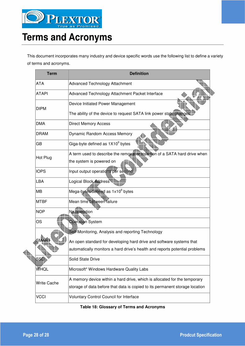
Terms and Acronyms
This document incorporates many industry and device specific words use the following list to define a variety
of terms and acronyms.
Term Definition
ATA Advanced Technology Attachment
ATAPI Advanced Technology Attachment Packet Interface
DIPM
Device Initiated Power Management
The ability of the device to request SATA link power state changes
DMA Direct Memory Access
DRAM Dynamic Random Access Memory
GB Giga-byte defined as 1X109 bytes
Hot Plug A term used to describe the removal or insertion of a SATA hard drive when
the system is powered on
IOPS Input output operations per second
LBA Logical Block Address
MB Mega-bytes defined as 1x106 bytes
MTBF Mean time between failure
NOP No operation
OS Operation System
SMART
Self-Monitoring, Analysis and reporting Technology
An open standard for developing hard drive and software systems that
automatically monitors a hard drive’s health and reports potential problems
SSD Solid State Drive
WHQL Microsoft* Windows Hardware Quality Labs
Write Cache A memory device within a hard drive, which is allocated for the temporary
storage of data before that data is copied to its permanent storage location
VCCI Voluntary Control Council for Interface
Table 18: Glossary of Terms and Acronyms