
PWA1529400000 rev8 Notice d'utilisation Instruction Notice ...
44
Notice dutilisation DCMT4™ PWF1529400000 / RØv.8 1 / 14 NOTICE D’UTILISATION Mise en service & Maintenance Dispositif numØrique de Contrle et de Mise la Terre DCMT4™ 8 05/03/21 J. FORTIN P. SURMAN M. LEGRAND Couleur des connecteurs non ATEX et consignes ESD 7 06/07/17 C. GODON S. SURGET P. SURMAN Mise jour nouvelle directive 2014/34/UE et plaque 6 03/02/17 C. GODON J. DELLARAGIONE P. SURMAN Ajout IPX6 et IPX7, mise jour pour SIL2 RØv. Date tabli VØrifiØ ApprouvØ Objet PEROLO SAS 69 rue des Maons TØl : 33(0) 5 57 42 67 00 33390 BLAYE Fax : 33(0) 5 57 42 67 01 France e-mail : [email protected] web : www.perolo.com
Transcript of PWA1529400000 rev8 Notice d'utilisation Instruction Notice ...

Notice dutilisation DCMT4 PWF1529400000 / Rév.8
1 / 14
NOTICE D'UTILISATION
Mise en service & Maintenance
Dispositif numérique de Contrôle et de Mise à la Terre
DCMT4
8 05/03/21 J. FORTIN P. SURMAN M. LEGRAND Couleur des connecteurs non ATEX et
consignes ESD
7 06/07/17C. GODON S. SURGET P. SURMAN
Mise à jour nouvelle directive 2014/34/UE et plaque
6 03/02/17 C. GODON J. DELLARAGIONE P. SURMAN Ajout IPX6 et IPX7, mise à jour pour
SIL2
Rév. Date Établi Vérifié Approuvé Objet
PEROLO SAS 69 rue des Maçons Tél : 33(0) 5 57 42 67 00 33390 BLAYE Fax : 33(0) 5 57 42 67 01 France e-mail : [email protected] web : www.perolo.com
Notice dutilisation DCMT4 PWF1529400000 / Rév.8
2 / 14
!
" #
" " $
% $
$
& $
$
'
!
!
! !
# !(
# )
# !
# !
# *+
# !
# ) *,$+
$ !
Notice dutilisation DCMT4 PWF1529400000 / Rév.8
3 / 14
1. FONCTIONS ET DESCRIPTIF DU DCMT4
1.1 Conditions d'utilisation au titre du mode de protection
Température ambiante dutilisation de -40°C à +70°C. Température recommandée dutilisation de -40°C à +50°C.
L'appareil est classifié en x II 2 (1) / 1GD au titre de la directive ATEX 2014/34/UE.
A titre d'information, cela signifie : - En mode poussière : boîtier utilisable en zones 21 et 22 ; pince utilisable en zones 20, 21 et 22. - En mode gaz : boîtier utilisable en zones 1 et 2 ; pince en zones 0, 1 et 2.
1.2 Fonctions du DCMT4
Le DCMT4 est un système de sécurité dont la fonction principale est dassurer la mise à la terre puis de contrôler son efficacité pendant une opération de transfert (chargement ou déchargement) dun réservoir qui contient des fluides dangereux.
Lors dune telle opération, il faut éviter la création dune étincelle entre le réservoir et linterface de connexion, puis évacuer lélectricité statique générée par les frottements entre les parois du réservoir et du produit en cours de transfert.
Pour cela, le réservoir doit être relié à la terre avant la connexion des interfaces puis le contrôle de cette liaison doit être effectué en continu pendant les opérations de chargement ou déchargement.
Des fonctions supplémentaires sont intégrées à lappareil : Différenciation entre un réservoir et un autre objet, Vérification continue du bon fonctionnement des 2 relais de mise à la terre en cas de défaut interne, Adaptation de lappareil aux conditions du site par programmation des paramètres de reconnaissance, Enregistrement et lecture des manipulations effectuées par lopérateur. La description plus détaillée de ces fonctions fait lobjet des paragraphes suivants.
1.3 Description de lappareil
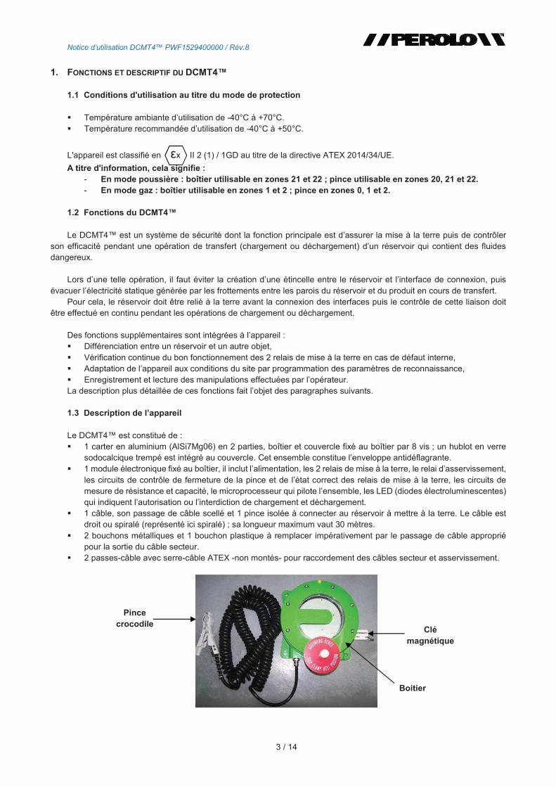
Le DCMT4 est constitué de : 1 carter en aluminium (AlSi7Mg06) en 2 parties, boîtier et couvercle fixé au boîtier par 8 vis ; un hublot en verre
sodocalcique trempé est intégré au couvercle. Cet ensemble constitue lenveloppe antidéflagrante. 1 module électronique fixé au boîtier, il inclut lalimentation, les 2 relais de mise à la terre, le relai dasservissement,
les circuits de contrôle de fermeture de la pince et de létat correct des relais de mise à la terre, les circuits de mesure de résistance et capacité, le microprocesseur qui pilote lensemble, les LED (diodes électroluminescentes) qui indiquent lautorisation ou linterdiction de chargement et déchargement.
1 câble, son passage de câble scellé et 1 pince isolée à connecter au réservoir à mettre à la terre. Le câble est droit ou spiralé (représenté ici spiralé) ; sa longueur maximum vaut 30 mètres.
2 bouchons métalliques et 1 bouchon plastique à remplacer impérativement par le passage de câble approprié pour la sortie du câble secteur.
2 passes-câble avec serre-câble ATEX -non montés- pour raccordement des câbles secteur et asservissement.
Clé magnétique
Boitier
Pince crocodile
Notice dutilisation DCMT4 PWF1529400000 / Rév.8
4 / 14
Principales caractéristiques techniques : Boîtier antidéflagrant, sortie du câble de pince en sécurité intrinsèque, marquages ci-après : Ex d [ia Ga]/ia IIC T6 Gb/Ga
Ex tb [ia Da]/ia IIIC T85°C Db/Da
x II 2(1)/1 GD
Étanchéité IP66 et IP67 suivant normes CEI 60529 édition 2013 et NF EN 60529 Alimentation électrique maximale 230VAC ou 115VAC Consommation maximum : 21W à 230VAC et 14W à 115VAC. Sécurité intrinsèque paramètre de sortie de linterface RS485 : U0:9.9V ; I0:44mA ; P0:109mW ; L0:3.5mH ;
C0:3.2F ; L0/R0:165H/ Système programmable : les valeurs de seuil sont paramétrables en fonction du site et des réservoirs. Electronique numérique : évolution possible du logiciel en fonction des besoins des utilisateurs. Système sécurisé par un haut pouvoir d'isolement des 2 relais de mise à la terre (10kV). Pavé de LED pour affichage (21 LED vertes, 21 LED rouges), 1 borne Bluetooth pour communication. Température de service : -40°C / +70°C. Pression de service : 80kPa à 110kPa, air à teneur normale en oxygène (21% v/v). Matériau : aluminium moulé AlSi7Mg06. Attestation d'examen CE de type LCIE 15 ATEX 3075X. Conforme SIL2 suivant IEC61058 édition avril 2012.
NOTA IMPORTANT : - L'utilisateur nest pas autorisé à modifier les composants mécaniques ou électroniques, une telle
intervention annulerait la certification atmosphères explosibles de lappareil. - Lutilisateur doit porter des gants de protection pour manipuler le DCMT4 et la pince. - De la même manière, seuls les composants dorigine doivent être utilisés pour garantir le mode de
protection (câble, pince, visserie, etc.). - Lutilisateur doit veiller à lutilisation correcte des passe-câbles. - Les bouchons et les passe-câbles doivent être serrés pour assurer létanchéité du boîtier. - Conditions spécifiques dutilisation :
1) La longueur maximale du câble de raccordement de la pince crocodile est de 30m. 2) Lappareil doit être connecté à un équipement certifié en sécurité intrinsèque ou un appareil
simple. Cette combinaison doit être compatible comme ce qui concerne les règles de sécurité intrinsèques (voir paramètres électrique).
3) Toutes les inscriptions doivent être équipées de passe câble Ex, déléments dobturation Ex ou adaptateurs Ex certifiés pour lutilisation prévue.
4) Les jeux antidéflagrants sont spécifiés avec des écarts maximaux plus petits que ceux indiqués dans la norme EN 60079-1 ; ils ne doivent pas être agrandis. Le fabricant doit être consulté pour les valeurs si nécessaire pour la maintenance.
5) Utiliser uniquement des vis de type BHC M8-30, classe A2-70 pour le couvercle.
VERIFICATION ET CONTROLE DE LAPPAREIL
Pour utiliser lappareil en toute sécurité, il faut régulièrement vérifier et contrôler létat de lappareil.
- Contrôle de la carte électronique à LED Avant chaque connexion de la pince
• Vérifier létat du panneau lumineux du DCMT4. Lorsque la pince nest pas connectée, les 3 LEDs vertes doivent clignoter. Dans le cas contraire, ne pas utiliser et connecter la pince, il y a un défaut sur lappareil, contacter le SAV.
• Lorsque que la pince est connectée, vérifier que les LEDs ne clignotent pas. Si les LEDs clignotent, cela signifie quil y a un défaut de relais.
• Vérifier que les LEDs soient fonctionnelles, elles doivent toutes pouvoir sallumer et séteindre correctement. (3 LEDs primaires vertes et rouges, 21 LEDs secondaires vertes et rouges)
Si les LEDs de la carte sont allumées pendant plus de 4h, lappareil se met en alarme.
Notice dutilisation DCMT4 PWF1529400000 / Rév.8
5 / 14
- Contrôle et état de la pince Il faut régulièrement vérifier létat de la pince. Avant chaque utilisation :
• Vérifier que la pince soit fonctionnelle et pas de jeu dans laxe de la pince
• Vérifier que les bras de la pince ne soient pas collés
• Vérifier que la peinture de la pince ne soit pas écaillée Si la pince est écaillée, il faut la remplacer pour une pince ATEX
- Contrôle et état du câble Vérifier la longueur du câble, 30m maximum. Dans le cas contraire, modifier la longueur du câble sinon ne pas utiliser lappareil.
Chaque mois :
• Vérifier que la gaine du câble ne soit pas fendue ou craquée.
• Vérifier que le câble ne soit pas écrasé.
Si le câble est détérioré, il faut remplacer le câble, suivant les caractéristiques du câble ci-dessous : 2 fils de cuivre de section 2.5mm² isolés par du PVC Diamètre extérieur de gaine 10±1 mm Température dutilisation -30°C/+60°C Résistance 15/km à 20°C
Capacité 150 pF/m
Inductance 12 H/m
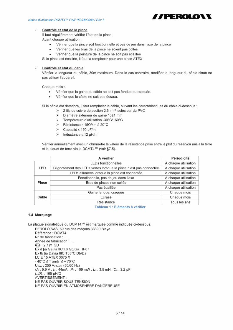
Vérifier annuellement avec un ohmmètre la valeur de la résistance prise entre le plot du réservoir mis à la terre et le piquet de terre via le DCMT4 (voir §7.5).
A verifier Périodicité
LED LEDs fonctionnelles A chaque utilisation
Clignotement des LEDs vertes lorsque la pince nest pas connectée A chaque utilisation
LEDs allumées lorsque la pince est connectée A chaque utilisation
Pince Fonctionnelle, pas de jeu dans laxe A chaque utilisation
Bras de pinces non collés A chaque utilisation
Pas écaillée A chaque utilisation
Câble Gaine fendue, craquée Chaque mois
Ecrasé Chaque mois
Résistance Tous les ans Tableau 1 : Eléments à vérifier
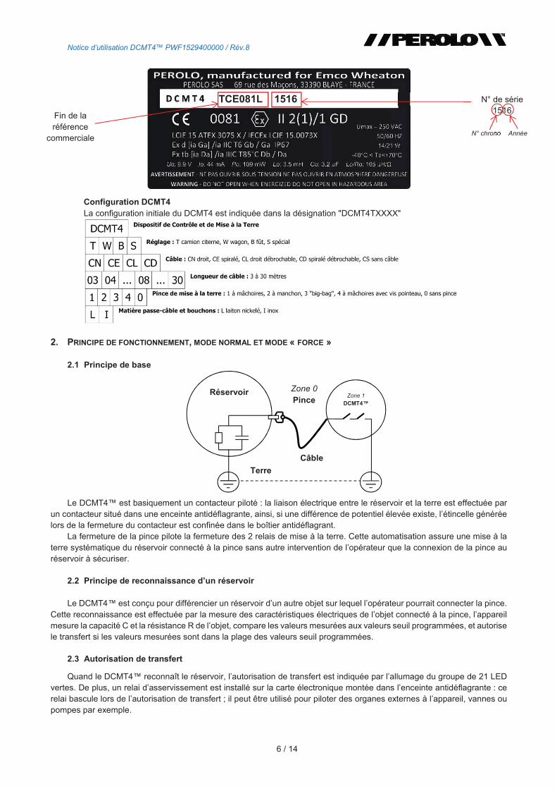
1.4 Marquage
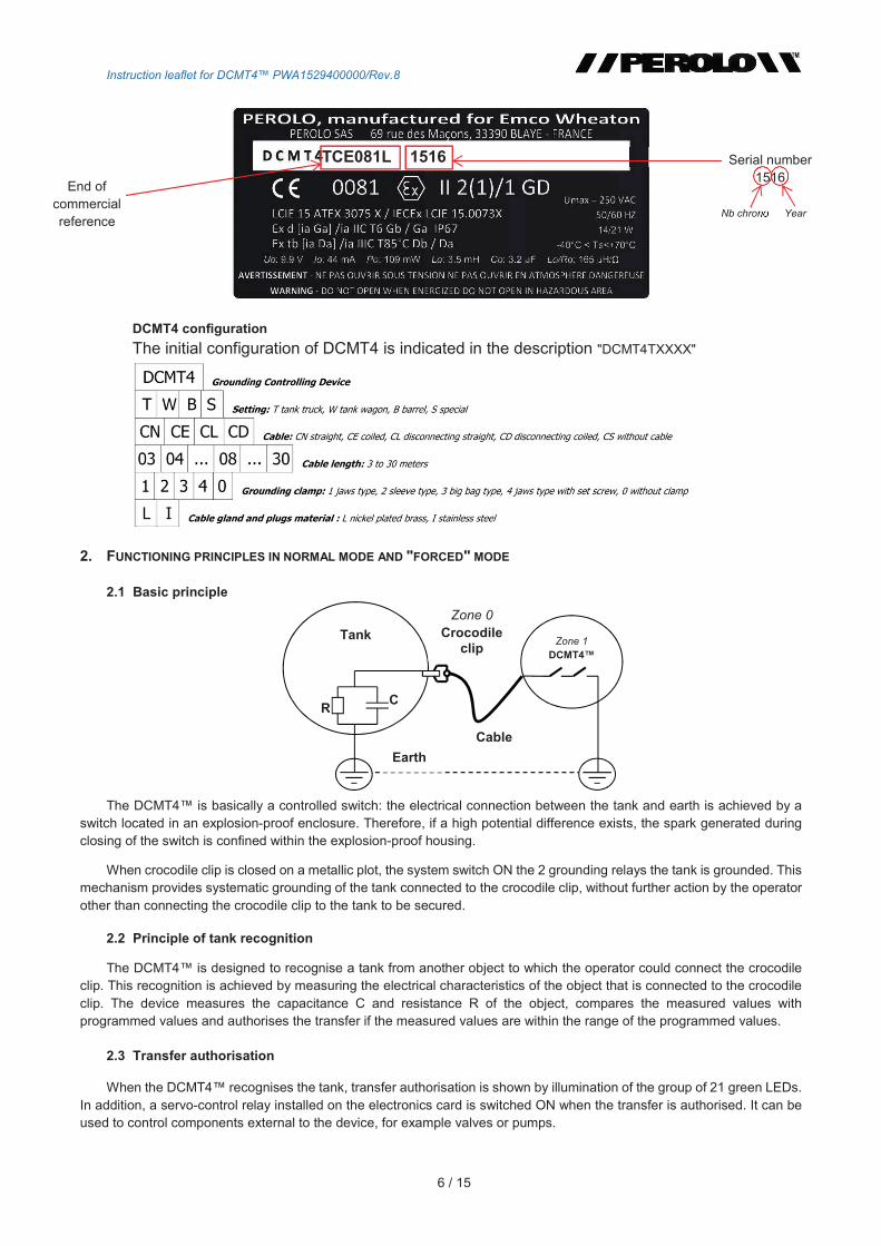
La plaque signalétique du DCMT4 est marquée comme indiquée ci-dessous. PEROLO SAS 69 rue des maçons 33390 Blaye Référence : DCMT4 N° de fabrication : Année de fabrication : x II 2(1)/1 GD
Ex d [ia Ga]/ia IIC T6 Gb/Ga IP67 Ex tb [ia Da]/ia IIIC T85°C Db/Da LCIE 15 ATEX 3075 X - 40°C T amb + 70°C Umax : 250 Vefficace (50/60 Hz) Uo : 9.9 V ; Io : 44mA ; Po : 109 mW ; Lo : 3.5 mH ; Co : 3.2 FLo/Ro : 165 H/AVERTISSEMENT : NE PAS OUVRIR SOUS TENSION NE PAS OUVRIR EN ATMOSPHERE DANGEREUSE
Notice dutilisation DCMT4 PWF1529400000 / Rév.8
6 / 14
Configuration DCMT4 La configuration initiale du DCMT4 est indiquée dans la désignation "DCMT4TXXXX"
2. PRINCIPE DE FONCTIONNEMENT, MODE NORMAL ET MODE « FORCE »
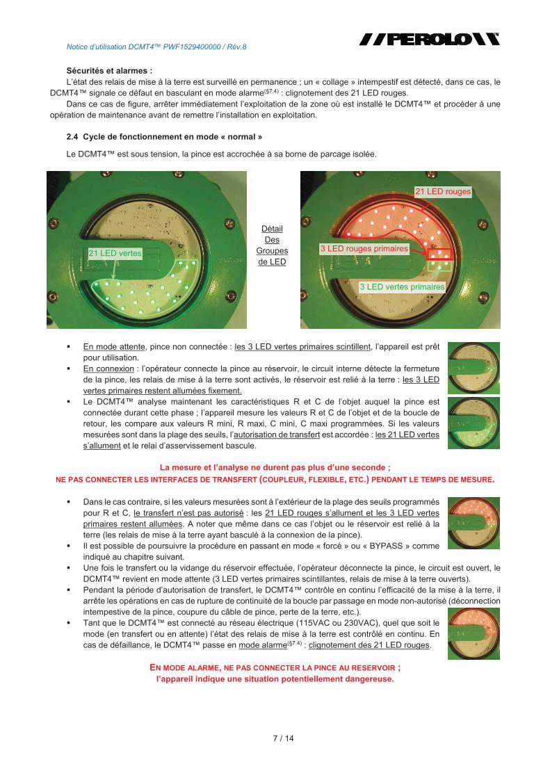
2.1 Principe de base
Le DCMT4 est basiquement un contacteur piloté : la liaison électrique entre le réservoir et la terre est effectuée par un contacteur situé dans une enceinte antidéflagrante, ainsi, si une différence de potentiel élevée existe, létincelle générée lors de la fermeture du contacteur est confinée dans le boîtier antidéflagrant.
La fermeture de la pince pilote la fermeture des 2 relais de mise à la terre. Cette automatisation assure une mise à la terre systématique du réservoir connecté à la pince sans autre intervention de lopérateur que la connexion de la pince au réservoir à sécuriser.
2.2 Principe de reconnaissance dun réservoir
Le DCMT4 est conçu pour différencier un réservoir dun autre objet sur lequel lopérateur pourrait connecter la pince. Cette reconnaissance est effectuée par la mesure des caractéristiques électriques de lobjet connecté à la pince, lappareil mesure la capacité C et la résistance R de lobjet, compare les valeurs mesurées aux valeurs seuil programmées, et autorise le transfert si les valeurs mesurées sont dans la plage des valeurs seuil programmées.
2.3 Autorisation de transfert
Quand le DCMT4 reconnaît le réservoir, lautorisation de transfert est indiquée par lallumage du groupe de 21 LED vertes. De plus, un relai dasservissement est installé sur la carte électronique montée dans lenceinte antidéflagrante : ce relai bascule lors de lautorisation de transfert ; il peut être utilisé pour piloter des organes externes à lappareil, vannes ou pompes par exemple.
Zone 1
DCMT4
Réservoir Zone 0
Pince
Câble
Terre
Fin de la référence
commerciale
TCE081L 1516 N° de série 1516
N° chrono Année
Notice dutilisation DCMT4 PWF1529400000 / Rév.8
7 / 14
Sécurités et alarmes : Létat des relais de mise à la terre est surveillé en permanence ; un « collage » intempestif est détecté, dans ce cas, le
DCMT4 signale ce défaut en basculant en mode alarme(§7.4) : clignotement des 21 LED rouges. Dans ce cas de figure, arrêter immédiatement lexploitation de la zone où est installé le DCMT4 et procéder à une
opération de maintenance avant de remettre linstallation en exploitation.
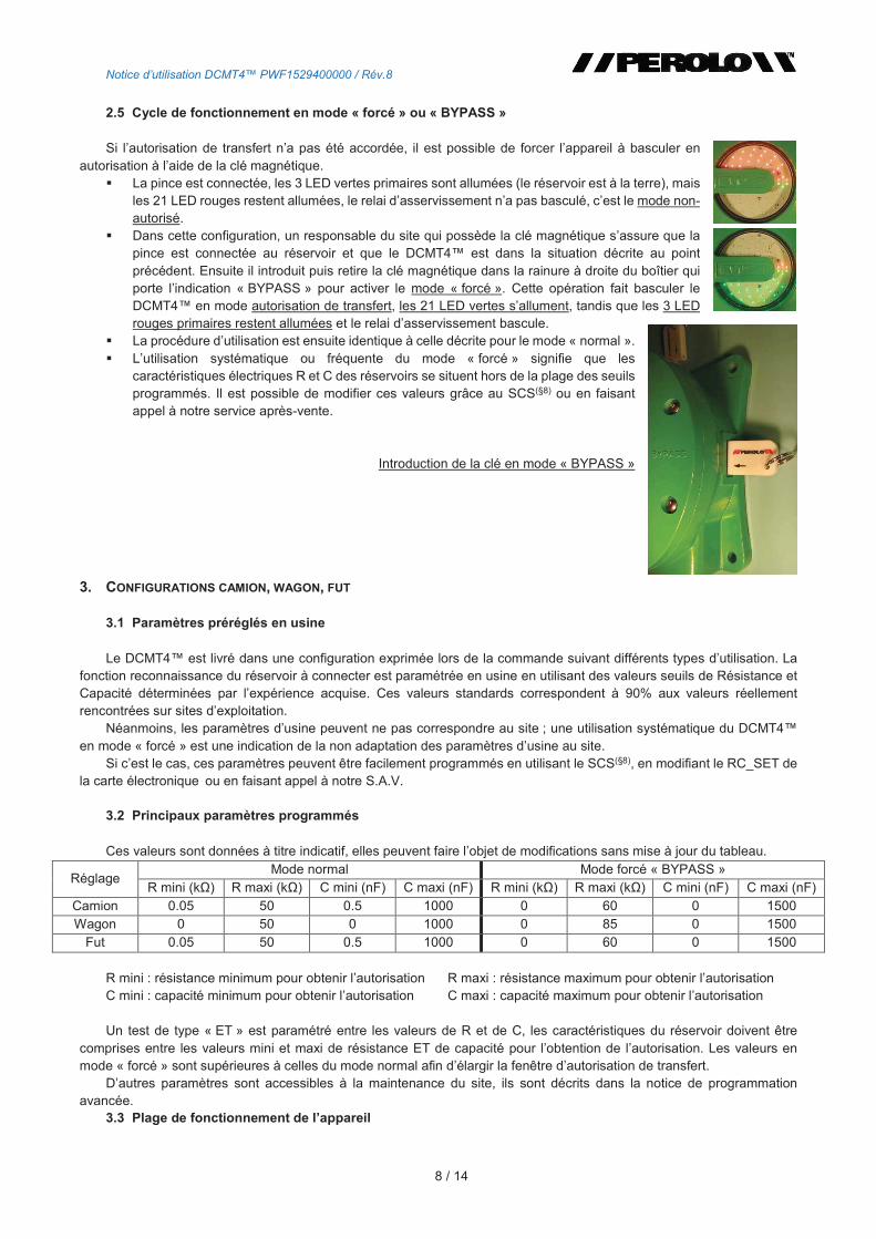
2.4 Cycle de fonctionnement en mode « normal »
Le DCMT4 est sous tension, la pince est accrochée à sa borne de parcage isolée.
En mode attente, pince non connectée : les 3 LED vertes primaires scintillent, lappareil est prêt pour utilisation.
En connexion : lopérateur connecte la pince au réservoir, le circuit interne détecte la fermeture de la pince, les relais de mise à la terre sont activés, le réservoir est relié à la terre : les 3 LED vertes primaires restent allumées fixement.
Le DCMT4 analyse maintenant les caractéristiques R et C de lobjet auquel la pince est connectée durant cette phase ; lappareil mesure les valeurs R et C de lobjet et de la boucle de retour, les compare aux valeurs R mini, R maxi, C mini, C maxi programmées. Si les valeurs mesurées sont dans la plage des seuils, lautorisation de transfert est accordée : les 21 LED vertes sallument et le relai dasservissement bascule.
La mesure et lanalyse ne durent pas plus dune seconde ;
NE PAS CONNECTER LES INTERFACES DE TRANSFERT (COUPLEUR, FLEXIBLE, ETC.) PENDANT LE TEMPS DE MESURE.
Dans le cas contraire, si les valeurs mesurées sont à lextérieur de la plage des seuils programmés pour R et C, le transfert nest pas autorisé : les 21 LED rouges sallument et les 3 LED vertes primaires restent allumées. A noter que même dans ce cas lobjet ou le réservoir est relié à la terre (les relais de mise à la terre ayant basculé à la connexion de la pince).
Il est possible de poursuivre la procédure en passant en mode « forcé » ou « BYPASS » comme indiqué au chapitre suivant.
Une fois le transfert ou la vidange du réservoir effectuée, lopérateur déconnecte la pince, le circuit est ouvert, le DCMT4 revient en mode attente (3 LED vertes primaires scintillantes, relais de mise à la terre ouverts).
Pendant la période dautorisation de transfert, le DCMT4 contrôle en continu lefficacité de la mise à la terre, il arrête les opérations en cas de rupture de continuité de la boucle par passage en mode non-autorisé (déconnection intempestive de la pince, coupure du câble de pince, perte de la terre, etc.).
Tant que le DCMT4 est connecté au réseau électrique (115VAC ou 230VAC), quel que soit le mode (en transfert ou en attente) létat des relais de mise à la terre est contrôlé en continu. En cas de défaillance, le DCMT4 passe en mode alarme(§7.4) : clignotement des 21 LED rouges.
EN MODE ALARME, NE PAS CONNECTER LA PINCE AU RESERVOIR ; lappareil indique une situation potentiellement dangereuse.
21 LED vertes
3 LED vertes primaires
3 LED rouges primaires
21 LED rouges
Détail Des
Groupes de LED
Notice dutilisation DCMT4 PWF1529400000 / Rév.8
8 / 14
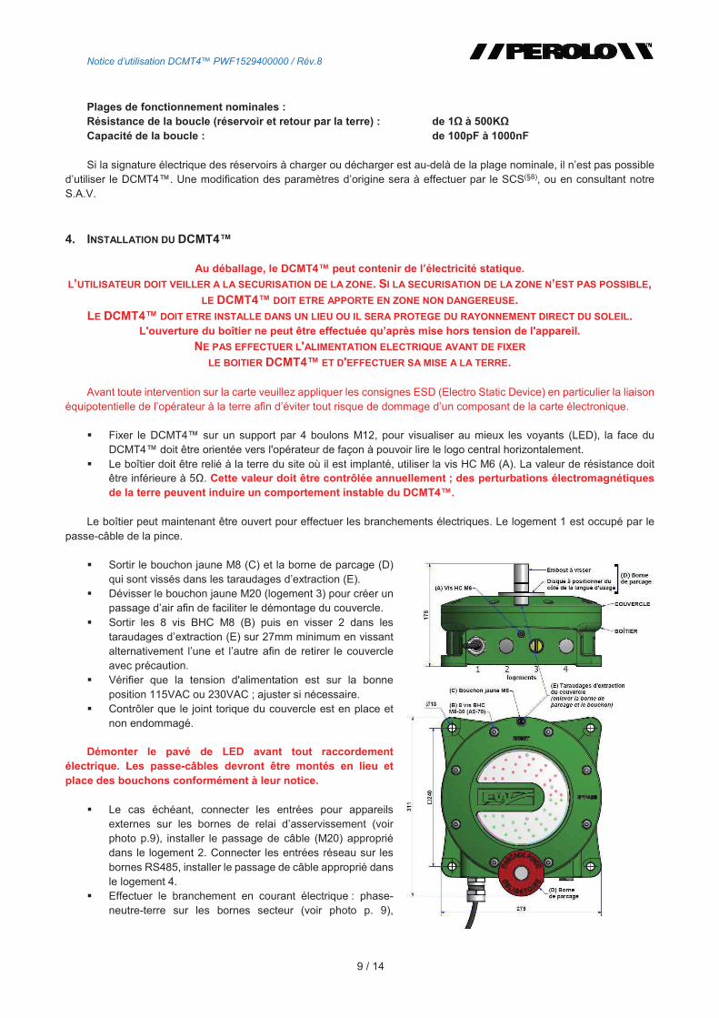
2.5 Cycle de fonctionnement en mode « forcé » ou « BYPASS »
Si lautorisation de transfert na pas été accordée, il est possible de forcer lappareil à basculer en autorisation à laide de la clé magnétique.
La pince est connectée, les 3 LED vertes primaires sont allumées (le réservoir est à la terre), mais les 21 LED rouges restent allumées, le relai dasservissement na pas basculé, cest le mode non-autorisé.
Dans cette configuration, un responsable du site qui possède la clé magnétique sassure que la pince est connectée au réservoir et que le DCMT4 est dans la situation décrite au point précédent. Ensuite il introduit puis retire la clé magnétique dans la rainure à droite du boîtier qui porte lindication « BYPASS » pour activer le mode « forcé ». Cette opération fait basculer le DCMT4 en mode autorisation de transfert, les 21 LED vertes sallument, tandis que les 3 LED rouges primaires restent allumées et le relai dasservissement bascule.
La procédure dutilisation est ensuite identique à celle décrite pour le mode « normal ». Lutilisation systématique ou fréquente du mode « forcé » signifie que les
caractéristiques électriques R et C des réservoirs se situent hors de la plage des seuils programmés. Il est possible de modifier ces valeurs grâce au SCS(§8) ou en faisant appel à notre service après-vente.
Introduction de la clé en mode « BYPASS »
3. CONFIGURATIONS CAMION, WAGON, FUT
3.1 Paramètres préréglés en usine
Le DCMT4 est livré dans une configuration exprimée lors de la commande suivant différents types dutilisation. La fonction reconnaissance du réservoir à connecter est paramétrée en usine en utilisant des valeurs seuils de Résistance et Capacité déterminées par lexpérience acquise. Ces valeurs standards correspondent à 90% aux valeurs réellement rencontrées sur sites dexploitation.
Néanmoins, les paramètres dusine peuvent ne pas correspondre au site ; une utilisation systématique du DCMT4 en mode « forcé » est une indication de la non adaptation des paramètres dusine au site.
Si cest le cas, ces paramètres peuvent être facilement programmés en utilisant le SCS(§8), en modifiant le RC_SET de la carte électronique ou en faisant appel à notre S.A.V.
3.2 Principaux paramètres programmés
Ces valeurs sont données à titre indicatif, elles peuvent faire lobjet de modifications sans mise à jour du tableau.
Réglage Mode normal Mode forcé « BYPASS »
R mini (k) R maxi (k) C mini (nF) C maxi (nF) R mini (k) R maxi (k) C mini (nF) C maxi (nF)
Camion 0.05 50 0.5 1000 0 60 0 1500 Wagon 0 50 0 1000 0 85 0 1500
Fut 0.05 50 0.5 1000 0 60 0 1500
R mini : résistance minimum pour obtenir lautorisation R maxi : résistance maximum pour obtenir lautorisation C mini : capacité minimum pour obtenir lautorisation C maxi : capacité maximum pour obtenir lautorisation
Un test de type « ET » est paramétré entre les valeurs de R et de C, les caractéristiques du réservoir doivent être comprises entre les valeurs mini et maxi de résistance ET de capacité pour lobtention de lautorisation. Les valeurs en mode « forcé » sont supérieures à celles du mode normal afin délargir la fenêtre dautorisation de transfert.
Dautres paramètres sont accessibles à la maintenance du site, ils sont décrits dans la notice de programmation avancée.
3.3 Plage de fonctionnement de lappareil
Notice dutilisation DCMT4 PWF1529400000 / Rév.8
9 / 14
Plages de fonctionnement nominales : Résistance de la boucle (réservoir et retour par la terre) : de 1 à 500KCapacité de la boucle : de 100pF à 1000nF
Si la signature électrique des réservoirs à charger ou décharger est au-delà de la plage nominale, il nest pas possible dutiliser le DCMT4. Une modification des paramètres dorigine sera à effectuer par le SCS(§8), ou en consultant notre S.A.V.
4. INSTALLATION DU DCMT4
Au déballage, le DCMT4 peut contenir de lélectricité statique.
LUTILISATEUR DOIT VEILLER A LA SECURISATION DE LA ZONE. SI LA SECURISATION DE LA ZONE NEST PAS POSSIBLE,LE DCMT4 DOIT ETRE APPORTE EN ZONE NON DANGEREUSE.
LE DCMT4 DOIT ETRE INSTALLE DANS UN LIEU OU IL SERA PROTEGE DU RAYONNEMENT DIRECT DU SOLEIL. L'ouverture du boîtier ne peut être effectuée quaprès mise hors tension de l'appareil.
NE PAS EFFECTUER L'ALIMENTATION ELECTRIQUE AVANT DE FIXER
LE BOITIER DCMT4 ET D'EFFECTUER SA MISE A LA TERRE.
Avant toute intervention sur la carte veuillez appliquer les consignes ESD (Electro Static Device) en particulier la liaison équipotentielle de lopérateur à la terre afin déviter tout risque de dommage dun composant de la carte électronique.
Fixer le DCMT4 sur un support par 4 boulons M12, pour visualiser au mieux les voyants (LED), la face du DCMT4 doit être orientée vers l'opérateur de façon à pouvoir lire le logo central horizontalement.
Le boîtier doit être relié à la terre du site où il est implanté, utiliser la vis HC M6 (A). La valeur de résistance doit être inférieure à 5. Cette valeur doit être contrôlée annuellement ; des perturbations électromagnétiques de la terre peuvent induire un comportement instable du DCMT4.
Le boîtier peut maintenant être ouvert pour effectuer les branchements électriques. Le logement 1 est occupé par le passe-câble de la pince.
Sortir le bouchon jaune M8 (C) et la borne de parcage (D) qui sont vissés dans les taraudages dextraction (E).
Dévisser le bouchon jaune M20 (logement 3) pour créer un passage dair afin de faciliter le démontage du couvercle.
Sortir les 8 vis BHC M8 (B) puis en visser 2 dans les taraudages dextraction (E) sur 27mm minimum en vissant alternativement lune et lautre afin de retirer le couvercle avec précaution.
Vérifier que la tension d'alimentation est sur la bonne position 115VAC ou 230VAC ; ajuster si nécessaire.
Contrôler que le joint torique du couvercle est en place et non endommagé.
Démonter le pavé de LED avant tout raccordement électrique. Les passe-câbles devront être montés en lieu et place des bouchons conformément à leur notice.
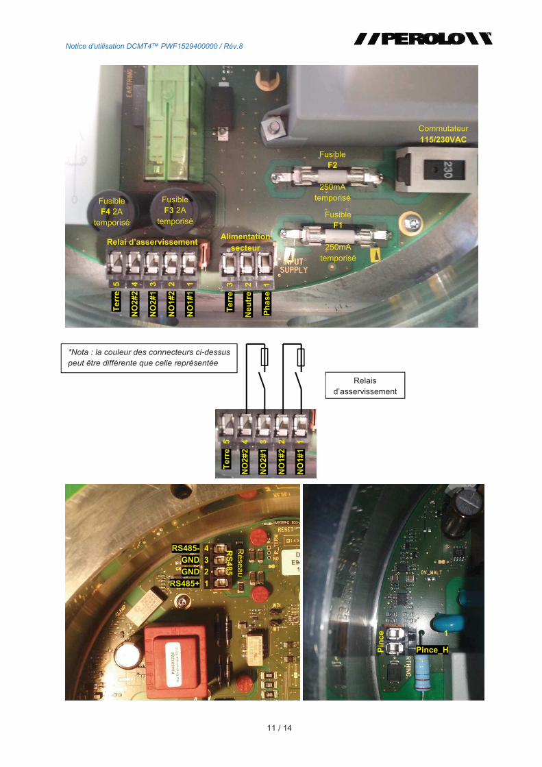
Le cas échéant, connecter les entrées pour appareils externes sur les bornes de relai dasservissement (voir photo p.9), installer le passage de câble (M20) approprié dans le logement 2. Connecter les entrées réseau sur les bornes RS485, installer le passage de câble approprié dans le logement 4.
Effectuer le branchement en courant électrique : phase-neutre-terre sur les bornes secteur (voir photo p. 9),
Notice dutilisation DCMT4 PWF1529400000 / Rév.8
10 / 14
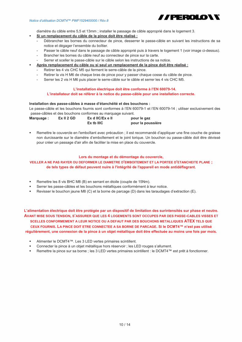
diamètre du câble entre 5,5 et 13mm ; installer le passage de câble approprié dans le logement 3. Si un remplacement du câble de la pince doit être réalisé :
- Débrancher les bornes du connecteur de pince, desserrer le passe-câble en suivant les instructions de sa notice et dégager lensemble du boîtier.
- Passer le câble neuf dans le passage de câble approprié puis à travers le logement 1 (voir image ci-dessus). - Brancher les bornes du câble neuf au connecteur de pince sur la carte. - Serrer et sceller le passe-câble sur le câble selon les instructions de sa notice.
Après remplacement du câble ou si seul un remplacement de la pince doit être réalisé : - Retirer les 4 vis CHC M5 qui ferment le serre-câble de la pince. - Retirer la vis H M6 de chaque bras de pince pour y passer chaque cosse du câble de pince. - Serrer les 2 vis H M6 puis placer le serre-câble sur le câble et serrer les 4 vis CHC M5.
Linstallation électrique doit être conforme à lEN 60079-14. Linstallateur doit se référer à la notice du passe-câble pour une installation correcte.
Installation des passe-câbles à masse détanchéité et des bouchons : Le passe-câble et les bouchons fournis sont conformes à lEN 60079-1 et lEN 60079-14 ; utiliser exclusivement des passe-câbles et des bouchons conformes au marquage suivant.
Marquage : Ex II 2 GD Ex d IIC/Ex e II pour le gazEx tb IIIC pour la poussière
Remettre le couvercle en l'emboîtant avec précaution ; il est recommandé dappliquer une fine couche de graisse non durcissante sur le diamètre demboîtement et le joint torique. Un bouchon ou passe-câble doit être dévissé pour créer un passage d'air afin de faciliter la mise en place du couvercle.
Lors du montage et du démontage du couvercle,
VEILLER A NE PAS RAYER OU DEFORMER LE DIAMETRE D'EMBOITEMENT ET LA PORTEE D'ETANCHEITE PLANE ; de tels types de défaut peuvent nuire à l'intégrité de l'appareil en mode antidéflagrant.
Remettre les 8 vis BHC M8 (B) en serrant en étoile (couple de 15Nm). Serrer les passe-câbles et les bouchons métalliques conformément à leur notice. Revisser le bouchon jaune M8 (C) et la borne de parcage (D) dans les taraudages dextraction (E).
Lalimentation électrique doit être protégée par un dispositif de limitation des surintensités sur phase et neutre.
AVANT MISE SOUS TENSION, SASSURER QUE LES 4 LOGEMENTS SONT OCCUPES PAR DES PASSE-CABLES VISSES ET
SCELLES CONFORMEMENT A LEUR NOTICE OU A DEFAUT PAR DES BOUCHONS METALLIQUES ATEX TELS QUE
CEUX FOURNIS. LA PINCE DOIT ETRE CONNECTEE A SA BORNE DE PARCAGE. Si le DCMT4 nest pas utilisé régulièrement, une connexion de la pince à un objet métallique doit être effectuée au moins une fois par mois.
Alimenter le DCMT4. Les 3 LED vertes primaires scintillent. Connecter la pince à un objet métallique hors réservoir ; les LED rouges sallument. Remettre la pince sur sa borne ; les 3 LED vertes primaires scintillent : le DCMT4 est prêt à fonctionner.
Notice dutilisation DCMT4 PWF1529400000 / Rév.8
11 / 14
Commutateur 115/230VAC
Te
rre
3
Ne
utr
e
2
Ph
as
e 1
Fusible F2
250mA temporisé
Fusible F1
250mA temporisé
Fusible F3 2A
temporisé
Alimentationsecteur
Te
rre
5
NO
2#
2
4
NO
2#
1
3
NO
1#
2
2
NO
1#
1
1
Relai dasservissement
Fusible F4 2A
temporisé
RS485- 4
GND 3
GND 2
RS485+ 1
Ré
sea
u R
S4
85
1
Pince_H Pin
ce
Te
rre
5
NO
2#
2
4
NO
2#
1
3
NO
1#
2
2
NO
1#
1
1
Relais dasservissement
*Nota : la couleur des connecteurs ci-dessus
peut être différente que celle représentée
Notice dutilisation DCMT4 PWF1529400000 / Rév.8
12 / 14
5. VERIFICATION DU FONCTIONNEMENT
PREALABLE : Si le DCMT4 nest pas utilisé régulièrement, une vérification simple par connexion de la pince à un objet
métallique doit être effectuée au moins une fois par mois.
5.1 Vérification basique sans le boîtier test
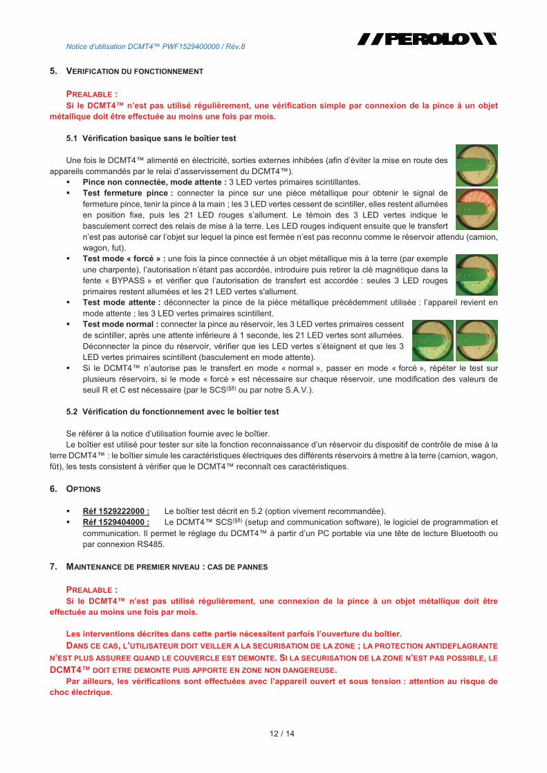
Une fois le DCMT4 alimenté en électricité, sorties externes inhibées (afin déviter la mise en route des appareils commandés par le relai dasservissement du DCMT4).
Pince non connectée, mode attente : 3 LED vertes primaires scintillantes. Test fermeture pince : connecter la pince sur une pièce métallique pour obtenir le signal de
fermeture pince, tenir la pince à la main ; les 3 LED vertes cessent de scintiller, elles restent allumées en position fixe, puis les 21 LED rouges sallument. Le témoin des 3 LED vertes indique le basculement correct des relais de mise à la terre. Les LED rouges indiquent ensuite que le transfert nest pas autorisé car lobjet sur lequel la pince est fermée nest pas reconnu comme le réservoir attendu (camion, wagon, fut).
Test mode « forcé » : une fois la pince connectée à un objet métallique mis à la terre (par exemple une charpente), lautorisation nétant pas accordée, introduire puis retirer la clé magnétique dans la fente « BYPASS » et vérifier que lautorisation de transfert est accordée : seules 3 LED rouges primaires restent allumées et les 21 LED vertes s'allument.
Test mode attente : déconnecter la pince de la pièce métallique précédemment utilisée : lappareil revient en mode attente ; les 3 LED vertes primaires scintillent.
Test mode normal : connecter la pince au réservoir, les 3 LED vertes primaires cessent de scintiller, après une attente inférieure à 1 seconde, les 21 LED vertes sont allumées. Déconnecter la pince du réservoir, vérifier que les LED vertes séteignent et que les 3 LED vertes primaires scintillent (basculement en mode attente).
Si le DCMT4 nautorise pas le transfert en mode « normal », passer en mode « forcé », répéter le test sur plusieurs réservoirs, si le mode « forcé » est nécessaire sur chaque réservoir, une modification des valeurs de seuil R et C est nécessaire (par le SCS(§8) ou par notre S.A.V.).
5.2 Vérification du fonctionnement avec le boîtier test
Se référer à la notice dutilisation fournie avec le boîtier. Le boîtier est utilisé pour tester sur site la fonction reconnaissance dun réservoir du dispositif de contrôle de mise à la
terre DCMT4 : le boîtier simule les caractéristiques électriques des différents réservoirs à mettre à la terre (camion, wagon, fût), les tests consistent à vérifier que le DCMT4 reconnaît ces caractéristiques.
6. OPTIONS
Réf 1529222000 : Le boîtier test décrit en 5.2 (option vivement recommandée). Réf 1529404000 : Le DCMT4 SCS(§8) (setup and communication software), le logiciel de programmation et
communication. Il permet le réglage du DCMT4 à partir dun PC portable via une tête de lecture Bluetooth ou par connexion RS485.
7. MAINTENANCE DE PREMIER NIVEAU : CAS DE PANNES
PREALABLE : Si le DCMT4 nest pas utilisé régulièrement, une connexion de la pince à un objet métallique doit être
effectuée au moins une fois par mois.
Les interventions décrites dans cette partie nécessitent parfois louverture du boîtier.
DANS CE CAS, LUTILISATEUR DOIT VEILLER A LA SECURISATION DE LA ZONE ; LA PROTECTION ANTIDEFLAGRANTE
NEST PLUS ASSUREE QUAND LE COUVERCLE EST DEMONTE. SI LA SECURISATION DE LA ZONE NEST PAS POSSIBLE, LE
DCMT4 DOIT ETRE DEMONTE PUIS APPORTE EN ZONE NON DANGEREUSE. Par ailleurs, les vérifications sont effectuées avec lappareil ouvert et sous tension : attention au risque de
choc électrique.

Notice dutilisation DCMT4 PWF1529400000 / Rév.8
13 / 14
7.1 Le DCMT4 est branché au secteur, aucune LED nest allumée
7.1.1 Défaut dalimentation électrique Démontage du couvercle, vérifier la présence de tension aux bornes de lalimentation électrique ; si la tension est
présente en entrée, la défaillance provient du fusible de protection dalimentation secteur F1 ou F2 (voir positions et caractéristiques sur la photo p.9) qui doit être changé.
7.1.2 Si le défaut persiste Après changement des fusibles, consulter notre SAV pour un retour de carte.
7.2 La pince est connectée au réservoir, lautorisation de transfert nest pas accordée
7.2.1 Les 3 LED vertes primaires ne scintillent plus, les 21 LED rouges sont allumées Sassurer de la bonne chronologie des opérations : connexion pince puis connexion des interfaces mécaniques.
Recommencer le cycle dans le bon ordre. Les caractéristiques électriques du réservoir sont au-delà de la fenêtre des paramètres programmés : lire avec le
SCS(§8) les valeurs R et C mesurées par le DCMT4, modifier les valeurs seuil de R et C pour adapter la fenêtre des seuils aux valeurs mesurées sur le site, ce paramétrage sera effectué soit par un utilisateur avancé avec le SCS(§8) soit en faisant appel à notre S.A.V. En attendant cette modification des paramètres, lexploitation peut continuer en utilisant le mode « BYPASS ».
Si le problème persiste en mode « BYPASS » : nous sommes de nouveau confrontés à une modification des paramètres de seuil de R et C mais pour le mode « BYPASS » ; élargir la fenêtre dautorisation en R et C grâce au SCS(§8) ou contacter le SAV.
LA PROGRAMMATION PAR LE SCS(§8) NECESSITE LUTILISATION DUN PC ATEX OU LA MISE EN SECURITE DE LA
ZONE OU EST INSTALLE LE DCMT4. SINON DEMONTER LE DCMT4 DE LA ZONE POUR PROGRAMMATION DANS UNE
ZONE OU LE PC PEUT ETRE UTILISE SANS RISQUE.
7.2.2 Les 3 LED vertes continuent de scintiller, les relais de mise à la terre ne basculent pas Défaillance du câble de liaison ou de la pince : démontage du DCMT4 de la zone dangereuse, test hors zone :
démontage du couvercle, déconnecter les 2 arrivées du câble de la pince de leurs bornes, mettre en tension, relier les 2 bornes avec un conducteur, si les 3 LED vertes cessent de scintiller, il sagit dune défaillance du câble de liaison ou de la pince ; changer le câble ou la pince(§0).
Sinon, défaillance carte : consulter notre SAV pour un retour de la carte.
7.3 Pas de signal en sortie de relai dasservissement
Vérification et remplacement éventuel du fusible de protection des relais F3 ou F4 défectueux (voir photo p.9) ; si la défaillance subsiste, consulter notre SAV pour un retour de la carte.
7.4 Clignotement des LED rouges (mode alarme)
NE PAS CONNECTER LA PINCE AU RESERVOIR SI LES LED ROUGES CLIGNOTENT OU SCINTILLENT.
Le fonctionnement correct des relais de mise à la terre est testé en continu. Une défaillance des contacts peut amener à une situation dangereuse : si les contacts dun relai de mise à la terre sont « collés », et si aucun signal nindique la défaillance, un risque détincelle existe entre la pince et le réservoir au moment de la connexion de la pince.
Le mode alarme du DCMT4 indique donc une défaillance des relais de mise à la terre ou du relai dasservissement par un clignotement des LED rouges ; arrêter les opérations de transfert.
Définition des alarmes : - Alarme bloquante (1 cas) : Les deux relais sont bloqués- Alarme non bloquante (5 cas) :
Un relais bloqué Relais de déchargement défaillant Capacité test défaillante Pince connecté plus de 4h Fausse alarme (ex : pince connecté sur passe câble)
Notice dutilisation DCMT4 PWF1529400000 / Rév.8
14 / 14
7.4.1 Déconnecter la pince du réservoir et effectuer un « RESET » Positionner la pince sur la borne de parcage. Pour cela introduire la clé magnétique dans la fente « RESET ». Connecter la pince sur le châssis. Si après le « RESET », lappareil revient en mode normal, brancher la pince sur la charpente pendant 3s pour
vérifier que le DCMT4 nest pas en alarme bloquante. Il sagit dune alarme non bloquante (carte défaillante ou DCMT4 non utilisé depuis longtemps)
Si le DCMT4 passe en mode alarme, refaire le test sur la charpente. Sil y a toujours lalarme, la carte possède un vrai problème elle doit être réparée.
7.4.2 Si le problème persiste avec scintillement des LED rouges : alarme bloquante Consulter notre SAV pour un retour de carte. Ou recharger le programme dans lappareil (voir notice logiciel §10)
7.4.3 Si le problème persiste après avoir rechargé le programme dans le DCMT4 : alarme bloquante Consulter notre SAV pour un retour de carte.
7.5 Vérification de la résistance du dispositif
Vérifier annuellement avec un ohmmètre la valeur de la résistance prise entre le plot du réservoir mis à la terre et le piquet de terre via le DCMT4.
Cette mesure permet de vérifier que : les relais de mise à la terre du DCMT4 sont opérants, le câble nest pas abimé. La valeur de résistance doit être inférieure à 5.
7.6 Perte de lheure sur le SCS(§8)
Lheure indiquée lors de lutilisation du SCS(§8) est revenue à zéro : cela indique que la pile de mémoire est vide. Le DCMT4 va continuer de fonctionner correctement. Consulter notre SAV pour un retour de la carte, seulement si
nécessaire.
8. UTILISATION AVANCEE, PARAMETRAGE
Les paramètres dorigine programmés dans le DCMT4 peuvent être modifiés par lutilisateur pour adapter lappareil aux conditions du site et des réservoirs. Les notices de programmation sont fournies avec les accessoires qui permettent la programmation :
Réf 1529404000 : Le DCMT4 SCS (setup and communication software), le logiciel de programmation et communication. Il permet le réglage du DCMT4 à partir dun PC portable via une tête de lecture Bluetooth ou par connexion RS485 via le passage de câble approprié si lutilisation est faite en zone ATEX ; cette option permet à lutilisateur de : - Lire en temps réel la capacité et la résistance mesurées, - Régler les seuils de capacité et résistance afin de les adapter au site, - Récupérer les événements qui se sont produits pendant lutilisation du DCMT4 : tels que connexions de
pince (dates et heures de connexions), utilisation du « BYPASS », diagnostic de pannes, lecture des résistances et capacités du réservoir connecté.
CE TYPE DE PROGRAMMATION NECESSITE LUTILISATION DUN PC ATEX OU LA MISE EN
SECURITE DE LA ZONE OU EST INSTALLE LE DCMT4. SINON DEMONTER LE DCMT4 DE LA ZONE POUR
PROGRAMMATION DANS UNE ZONE OU LE PC PEUT ETRE UTILISE SANS RISQUE.

Instruction leaflet for DCMT4 PWA1529400000/Rev.8
1 / 15
INSTRUCTION NOTICE
Commissioning & Maintenance
Digital Control Grounding Device DCMT4
8 05/03/21J. FORTIN P. SURMAN M. LEGRAND
Color connectors and ESD cautions
7 06/07/17 C. GODON J. DELLARAGIONE P. SURMAN Mise à jour nouvelle directive et
nouvelle plaque
6 03/02/17 C. GODON J. DELLARAGIONE P. SURMAN Ajout IPX6 et IPX7, mise à jour pour
SIL2
Rev. Date Prepared by Checked by Approved by Purpose
PEROLO SAS 69 rue des Maçons Tel: +33 (0)5 57 42 67 00 33390 BLAYE Fax: +33 (0)5 57 42 67 01 France e-mail: [email protected] website: www.perolo.com
Instruction leaflet for DCMT4 PWA1529400000/Rev.8
2 / 15
!
"# !
!
!
$
$
#
#
%&#
%
'(
')!(
! "
Instruction leaflet for DCMT4 PWA1529400000/Rev.8
3 / 15
1. DCMT4 FUNCTIONS AND DESCRIPTION
1.1 Functioning conditions in protection mode
Ambient temperature -40 °C to +70 °C. Recommended temperature -40 °C to +50 °C.
The device is classified x II 2 (1) / 1GD under ATEX directive 2014/34/UE.
This means: - In dust mode: housing can be used in zones 21 and 22; crocodile clip usable in zones 20, 21 and 22. - In gas mode: housing can be used in zones 1 and 2; crocodile clip usable in zones 0, 1 and 2.
1.2 DCMT4 functions
The DCMT4 is a safety system which main functions ensures grounding and checking the grounding during loading or unloading containing hazardous fluids operations
It is mandatory that no spark is created between the tank and the connecting interface and that any possible static electricity generated by friction during this operation is evacuated.
For this, the tank must be grounded before connecting the piping interfaces and this connection must be continuously monitored during loading or unloading operation
Additional functions of the device are: Detecting the difference between a tank and another object, Checking constantly the 2 grounding relays in case of an internal fault, Adapting the device to site conditions by programming the recognition settings, to the tanks usually loaded Recording and interpreting the handling operations. A more detailed description of these functions is provided in the following paragraphs.
1.3 Device description
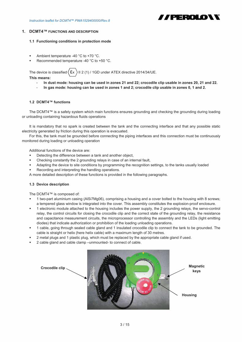
The DCMT4 is composed of: 1 two-part aluminium casing (AlSi7Mg06), comprising a housing and a cover bolted to the housing with 8 screws;
a tempered glass window is integrated into the cover. This assembly constitutes the explosion-proof enclosure. 1 electronic module attached to the housing includes the power supply, the 2 grounding relays, the servo-control
relay, the control circuits for closing the crocodile clip and the correct state of the grounding relay, the resistance and capacitance measurement circuits, the microprocessor controlling the assembly and the LEDs (light emitting diodes) that indicate authorization or prohibition of the loading unloading operations.
1 cable, going through sealed cable gland and 1 insulated crocodile clip to connect the tank to be grounded. The cable is straight or helix (here helix cable) with a maximum length of 30 metres.
2 metal plugs and 1 plastic plug, which must be replaced by the appropriate cable gland if used. 2 cable gland and cable clamp unmounted- to connect of cable.
Magnetickeys
Housing
Crocodile clip
Instruction leaflet for DCMT4 PWA1529400000/Rev.8
4 / 15
Main technical features: Explosion-proof housing, intrinsically safe cable circuit with crocodile clip : Ex d [ia Ga]/ia IIC T6 Gb/Ga
Ex tb [ia Da]/ia IIIC T85°C Db/Da
x II 2(1)/1 GD
Tightness IP66 and IP67 follow CEI 60529 2013 edition and NF EN 60529. Maximum electrical supply 230 VAC or 115 VAC Maximum power consumption: 21 W at 230 VAC and 14 W at 115 VAC. Intrinsic safety output parameter of RS485 interface : U0:9.9V ; I0:44mA ; P0:109mW ; L0:3.5mH ; C0:3.2F ;
L0/R0:165H/ Programmable system: the value range can be configured depending on the site and the tank. Digital electronics: software. System made safe by high level of isolation of the 2 grounding relays (10 kV). LED blocks for display (21 green LEDS, 21 red LEDS), 1 Bluetooth terminal for communication. Working temperature: -40 °C/+70 °C. Atmospheric pressure: 80 kPa to 110 kPa, air with normal oxygen content (21% by volume). Material: cast aluminium AlSi7Mg06. EC type-examination certificate LCIE 15 ATEX 3075X. Conform to SIL2 follow IEC61058 April 2012 edition.
IMPORTANT NOTE: - Do not modify the mechanical or electronic components; such intervention would alter the devices
explosive atmospheres certification. - The user must use protective gloves to handle the DCMT4 and the clips. - Only authentic components must be used to guarantee protection mode (cable, crocodile clips, screws
and bolts, etc.). - Ensure correct use of the cable gland. - Tighten the plugs and cable glands to ensure that the housing is sealed. - Specific condition of use :
1) The maximum length of connecting cable of the crocodile clip is 30m. 2) The equipment shall only be connected to intrinsically safe certified equipment or simple
apparatus. This combination must be compatible as regard the intrinsic safety rules (see electrical parameters in rating).
3) All entries must be equipped with Ex cable glands, Ex blanking elements or Ex thread adapters certified for the intended use.
4) The flamepaths are specified with maximum gaps smaller than those given in EN 60079-1 standard and shall not be enlarged. The manufacturer should be consulted for values if required for maintenance.
5) Use only screws type BHC M8-30, A2-70 class for cover.
CHECKING AND CONTROL OF THE EQUIPMENT
To use the equipment safely, check and control frequently the condition of the equipment.
- Control of the LED electronic card Before each connection of the clip
• Check the condition of the DCMT4 light board. When the clamp is not connected, the 3 green LEDs must blink. If not, do not use and connect the clip, there is a default in the device, contact the Customer Service.
• When the clip is connected, check that the LEDs dont blink. If the LEDs blink, it means that there is a default of relay.
• Check that the LEDs are operational, that they can switch on and switch off correctly. (3 primary green and red LEDs, 21 secondary green and red LEDs)
If the LEDs of the board are switched on for 4h, the device goes into alarm.
Instruction leaflet for DCMT4 PWA1529400000/Rev.8
5 / 15
- Control and state of the clamp Check frequently the state of the clip. Before each use :
• Check that the clip is functional and no backlash into the clamps axle
• Check that the arms clamp are not glued
• Check that the paint of the clamp is not scaled If the clamp is scaled, the clamp must be replaced by a ATEX clip
- Control and state of the cable Check the cables length, 30m maximum. If the cable is longer, reduce the cables length or do not use the device.
Each month :
• Check that the cables sheath not split or cracked is.
• Check that the cable is not crushed is
If the cable is damaged, it must be replaced, following the characteristics below : 2 copper wired of 2.5mm² section each wrapped with PVC Outside diameter sheath 10±1 mm Temperature -30°C/+60°C Resistance 15/km à 20°C
Capacitance 150 pF/m
Inductance 12 H/m
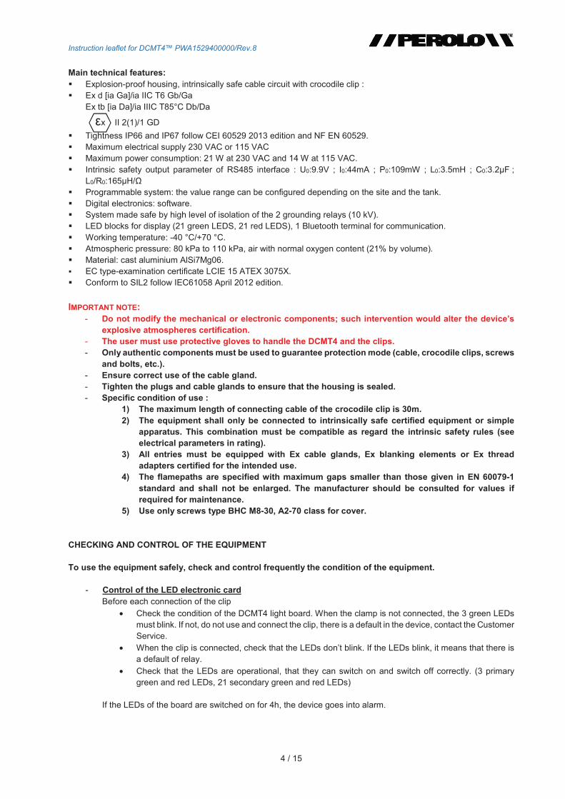
Check each year with an ohmmeter the value of the resistance between the grounded tank slot and the ground rod by the DCMT4 (see §7.5).
To chek Periodicity
LED LEDs operational Each usage
Flashing of green LEDs when the clip is not connected Each usage
LEDs switch on when the clip is connected Each usage
Clip Operational, no backlash on the clips axle Each usage
Clips bracket no glued Each usage
Clip not scaled Each usage
Cable Splited sheath, cracked Each month
Pressed Each month
Resistance Every year Table 1 : Elements to check
1.4 Marking
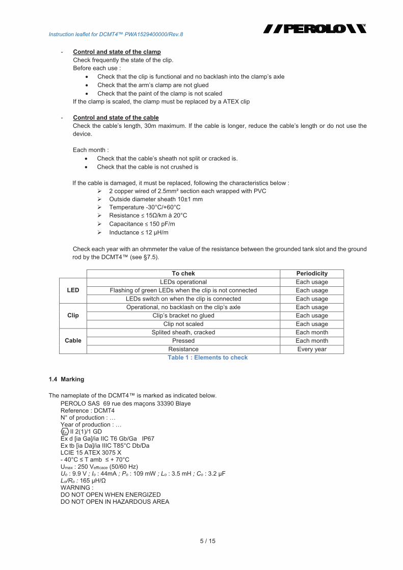
The nameplate of the DCMT4 is marked as indicated below. PEROLO SAS 69 rue des maçons 33390 Blaye Reference : DCMT4 N° of production : Year of production : x II 2(1)/1 GD
Ex d [ia Ga]/ia IIC T6 Gb/Ga IP67Ex tb [ia Da]/ia IIIC T85°C Db/Da LCIE 15 ATEX 3075 X - 40°C T amb + 70°C Umax : 250 Vefficace (50/60 Hz) Uo : 9.9 V ; Io : 44mA ; Po : 109 mW ; Lo : 3.5 mH ; Co : 3.2 FLo/Ro : 165 H/WARNING : DO NOT OPEN WHEN ENERGIZED DO NOT OPEN IN HAZARDOUS AREA
Instruction leaflet for DCMT4 PWA1529400000/Rev.8
6 / 15
DCMT4 configuration
The initial configuration of DCMT4 is indicated in the description "DCMT4TXXXX"
2. FUNCTIONING PRINCIPLES IN NORMAL MODE AND "FORCED" MODE
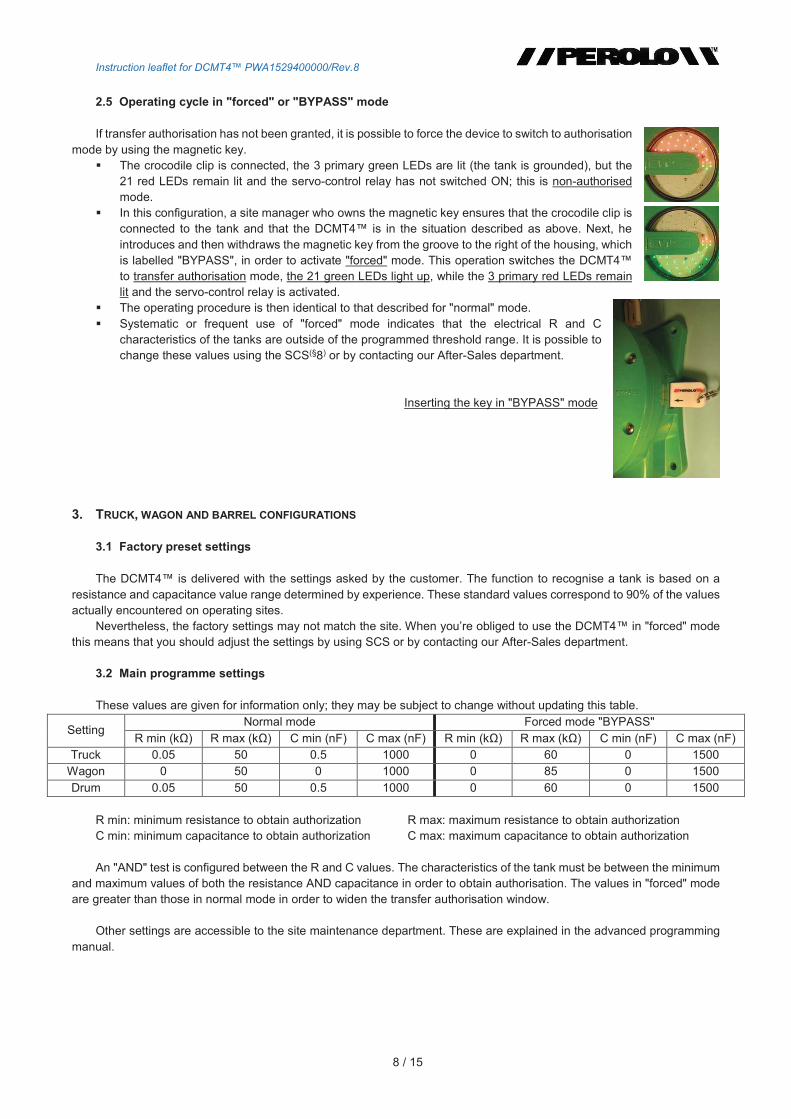
2.1 Basic principle
The DCMT4 is basically a controlled switch: the electrical connection between the tank and earth is achieved by a switch located in an explosion-proof enclosure. Therefore, if a high potential difference exists, the spark generated during closing of the switch is confined within the explosion-proof housing.
When crocodile clip is closed on a metallic plot, the system switch ON the 2 grounding relays the tank is grounded. This mechanism provides systematic grounding of the tank connected to the crocodile clip, without further action by the operator other than connecting the crocodile clip to the tank to be secured.
2.2 Principle of tank recognition
The DCMT4 is designed to recognise a tank from another object to which the operator could connect the crocodile clip. This recognition is achieved by measuring the electrical characteristics of the object that is connected to the crocodile clip. The device measures the capacitance C and resistance R of the object, compares the measured values with programmed values and authorises the transfer if the measured values are within the range of the programmed values.
2.3 Transfer authorisation
When the DCMT4 recognises the tank, transfer authorisation is shown by illumination of the group of 21 green LEDs. In addition, a servo-control relay installed on the electronics card is switched ON when the transfer is authorised. It can be used to control components external to the device, for example valves or pumps.
Zone 1
DCMT4
Tank
Zone 0
Crocodile clip
Cable
Earth
CR
TCE081L 1516
End of commercial reference
Serial number 1516
Nb chrono Year

Instruction leaflet for DCMT4 PWA1529400000/Rev.8
7 / 15
Safety devices and alarms: The status of the grounding relay is continuously monitored. If inopportune "sticking" is detected, then the DCMT4
signals this fault by switching to alarm mode(§7.4): the 21 red LEDs will flash. In this case, immediately stop working in the area where the DCMT4 is installed and perform maintenance before
going back to operations.
2.4 Operating cycle in "normal" mode
The DCMT4 is powered on, the crocodile clip is attached to its insulated parking pin.
In standby mode, the crocodile clip is not connected: The 3 primary green LEDs over flashing, the device is ready for use.
Upon connection: the operator connects the crocodile clip to the tank, the internal circuit detects the closing of the crocodile clip, the grounding relays are activated and the tank is grounded: The 3 primary green LEDs remain continuously lit.
The DCMT4 now analyses the R and C characteristics of the object to which the crocodile clip is connected during this phase; the device measures the R and C values of the object and the return circuit, and compares these with the programmed values: R min, R max, C min and C max. If the measured values are within the range of the thresholds, transfer authorisation is granted: The 21 green LEDs light up and the servo-control relay switches is activated.
Measuring and analysing last no more than one second;
DO NOT CONNECT THE PIPING CONNECTIONS (COUPLER, HOSE, ETC. ) DURING THE MEASUREMENT PERIOD.
If this is not the case and the measured values are outside the range of the programmed thresholds for R and C, the transfer is not authorised: the 21 red LEDs light up and the 3 primary green LEDs remain lit. Note that even in this case the object or tank is grounded (the grounding relay having switched during the crocodile clip connection to the tank).
It is possible to continue the procedure by changing to "forced" or "BYPASS" mode, as illustrated in the next section.
Once the transfer or draining of the tank is complete, the operator disconnects the crocodile clip, the circuit becomes open and the DCMT4 returns to standby mode (3 primary green LEDs flickering, grounding relays open).
During the transfer authorisation period, the DCMT4 continuously monitors the grounding efficient; it stops its functioning in the event of a break in continuity of the loop by changing to non-authorised mode (unexpected disconnection of the crocodile clip, cutting of the crocodile clip cable, loss of grounding, etc.).
As long as the DCMT4 is connected to the electrical power (115 VAC or 230 VAC), regardless of the mode (transfer or standby) the state of the grounding relay is continuously monitored. In the event of a fault, the DCMT4 switches to alarm mode (§7.4): 21 red LEDs flashing.
IN ALARM MODE, DO NOT CONNECT THE CROCODILE CLIP TO THE TANK; The device is indicating a potentially hazardous situation.
21 green LED
3 primary green LED
3 primary red LED
21 LED rouges
Overview of the
LED groups
Instruction leaflet for DCMT4 PWA1529400000/Rev.8
8 / 15
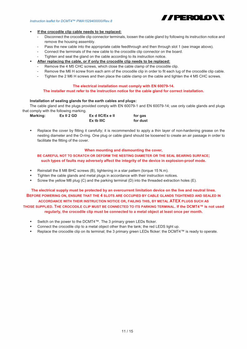
2.5 Operating cycle in "forced" or "BYPASS" mode
If transfer authorisation has not been granted, it is possible to force the device to switch to authorisation mode by using the magnetic key.
The crocodile clip is connected, the 3 primary green LEDs are lit (the tank is grounded), but the 21 red LEDs remain lit and the servo-control relay has not switched ON; this is non-authorised mode.
In this configuration, a site manager who owns the magnetic key ensures that the crocodile clip is connected to the tank and that the DCMT4 is in the situation described as above. Next, he introduces and then withdraws the magnetic key from the groove to the right of the housing, which is labelled "BYPASS", in order to activate "forced" mode. This operation switches the DCMT4 to transfer authorisation mode, the 21 green LEDs light up, while the 3 primary red LEDs remain lit and the servo-control relay is activated.
The operating procedure is then identical to that described for "normal" mode. Systematic or frequent use of "forced" mode indicates that the electrical R and C
characteristics of the tanks are outside of the programmed threshold range. It is possible to change these values using the SCS(§8) or by contacting our After-Sales department.
Inserting the key in "BYPASS" mode
3. TRUCK, WAGON AND BARREL CONFIGURATIONS
3.1 Factory preset settings
The DCMT4 is delivered with the settings asked by the customer. The function to recognise a tank is based on a resistance and capacitance value range determined by experience. These standard values correspond to 90% of the values actually encountered on operating sites.
Nevertheless, the factory settings may not match the site. When youre obliged to use the DCMT4 in "forced" mode this means that you should adjust the settings by using SCS or by contacting our After-Sales department.
3.2 Main programme settings
These values are given for information only; they may be subject to change without updating this table.
Setting Normal mode Forced mode "BYPASS"
R min (k) R max (k) C min (nF) C max (nF) R min (k) R max (k) C min (nF) C max (nF) Truck 0.05 50 0.5 1000 0 60 0 1500
Wagon 0 50 0 1000 0 85 0 1500
Drum 0.05 50 0.5 1000 0 60 0 1500
R min: minimum resistance to obtain authorization R max: maximum resistance to obtain authorizationC min: minimum capacitance to obtain authorization C max: maximum capacitance to obtain authorization
An "AND" test is configured between the R and C values. The characteristics of the tank must be between the minimum and maximum values of both the resistance AND capacitance in order to obtain authorisation. The values in "forced" mode are greater than those in normal mode in order to widen the transfer authorisation window.
Other settings are accessible to the site maintenance department. These are explained in the advanced programming manual.

Instruction leaflet for DCMT4 PWA1529400000/Rev.8
9 / 15
3.3 Operating range of the device
Nominal operating ranges: Circuit resistance (tank and return via earth): 1 to 500 kCircuit capacitance: 100 pF to 1000 nF
If the electrical signature of the tanks to be loaded or unloaded is outside the nominal range, it is difficult to use the DCMT4. You will need to modify its settings by using SCS, or by contacting our After-Sales department.
4. INSTALLATION OF THE DCMT4 During unpacking, the DCMT4 may hold static electricity.
THE USER MUST ENSURE THE SAFETY OF THE AREA. IF IT IS NOT POSSIBLE TO MAKE THE AREA SAFE, THE DCMT4MUST BE TAKEN TO A NON-HAZARDOUS AREA.
THE DCMT4 MUST BE INSTALLED IN A LOCATION WHERE IT WILL BE PROTECTED FROM DIRECT SUNLIGHT. The housing may only be opened after power off the device.
DO NOT SUPPLY ELECTRICAL POWER BEFORE FIXING
THE DCMT4 HOUSING IN PLACE AND ENSURING GROUNDING.
Before operating on the electronic board should the ESD precautions applied; specially operator-earth connection to avoid any damages on the board electronic component.
Attach the DCMT4 on a bracket using four M12 bolts, so that the window (LEDs) can be viewed as clearly as possible, the face of the DCMT4 must be oriented towards the operator in such a way that the central logo can be read horizontally.
The housing must be grounded on the site where it is located, using the HC M6 screw (A). The resistance value should be less than 5 . This value must be checked annually; the earths electromagnetic disturbances can induce unstable behaviour in the DCMT4.
The housing can now be opened in order to make the electrical connections. Slot 1 is used for the cable gland for the crocodile clips.
Remove the yellow M8 plug (C) and the parking terminal (D), which are screwed into the threaded extraction sockets (E).
Unscrew the yellow M20 plug (slot 3) to create an air passage, in order to facilitate removal of the cover.
Remove the 8 M8 BHC screws (B) and then screw two of these at least 27 mm into the threaded extraction sockets (E), alternately tightening one and then the other in order to carefully remove the cover.
Check that the supply voltage is set to the correct position, 115 VAC or 230 VAC; adjust if necessary.
Check that the O-ring for the lid is in place and undamaged.
Remove the LED block before making any electrical connections. The cable glands should be fitted in place and the plugs located according to the instructions.
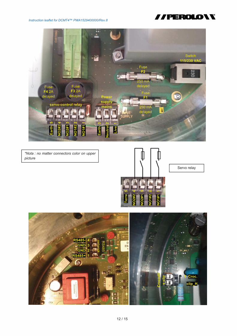
If applicable, connect the inputs for external devices to the servo-control relay terminals (see picture on page 9), install the appropriate cable feedthrough (M20) in slot 2. Connect the network input on the RS485 terminals, install the appropriate cable feedthrough in slot 4.
Connect the electrical power (live-neutral-earth) to the main terminals (see photograph on page 9), cable diameter between 5.5 and 13 mm; install the appropriate cable in slot 3.
(A) M6 HC screw
Connector to tighten
Disc to position from size of the use tongue
COVER
(C) Yellow M8 plug
(B) 8 M8-30 BHC screws (A2-70)
(E) Threaded cover extraction holes (to remove the parking terminal and plug)
(D) parking terminal
HOUSING
slots
(D) parking terminal

Instruction leaflet for DCMT4 PWA1529400000/Rev.8
10 / 15
Instruction leaflet for DCMT4 PWA1529400000/Rev.8
11 / 15
If the crocodile clip cable needs to be replaced: - Disconnect the crocodile clip connector terminals, loosen the cable gland by following its instruction notice and
remove the housing assembly. - Pass the new cable into the appropriate cable feedthrough and then through slot 1 (see image above). - Connect the terminals of the new cable to the crocodile clip connector on the board. - Tighten and seal the gland on the cable according to its instruction notice.
After replacing the cable, or if only the crocodile clip needs to be replaced: - Remove the 4 M5 CHC screws, which close the cable clamp of the crocodile clip. - Remove the M6 H screw from each arm of the crocodile clip in order to fit each lug of the crocodile clip cable. - Tighten the 2 M6 H screws and then place the cable clamp on the cable and tighten the 4 M5 CHC screws.
The electrical installation must comply with EN 60079-14. The installer must refer to the instruction notice for the cable gland for correct installation.
Installation of sealing glands for the earth cables and plugs: The cable gland and the plugs provided comply with EN 60079-1 and EN 60079-14; use only cable glands and plugs
that comply with the following marking. Marking: Ex II 2 GD Ex d IIC/Ex e II for gas
Ex tb IIIC for dust
Replace the cover by fitting it carefully; it is recommended to apply a thin layer of non-hardening grease on the nesting diameter and the O-ring. One plug or cable gland should be loosened to create an air passage in order to facilitate the fitting of the cover.
When mounting and dismounting the cover,
BE CAREFUL NOT TO SCRATCH OR DEFORM THE NESTING DIAMETER OR THE SEAL BEARING SURFACE; such types of faults may adversely affect the integrity of the device in explosion-proof mode.
Reinstall the 8 M8 BHC screws (B), tightening in a star pattern (torque 15 N.m). Tighten the cable glands and metal plugs in accordance with their instruction notices. Screw the yellow M8 plug (C) and the parking terminal (D) into the threaded extraction holes (E).
The electrical supply must be protected by an overcurrent limitation device on the live and neutral lines.
BEFORE POWERING ON, ENSURE THAT THE 4 SLOTS ARE OCCUPIED BY CABLE GLANDS TIGHTENED AND SEALED IN
ACCORDANCE WITH THEIR INSTRUCTION NOTICE OR, FAILING THIS, BY METAL ATEX PLUGS SUCH AS
THOSE SUPPLIED. THE CROCODILE CLIP MUST BE CONNECTED TO ITS PARKING TERMINAL. If the DCMT4 is not used regularly, the crocodile clip must be connected to a metal object at least once per month.
Switch on the power to the DCMT4. The 3 primary green LEDs flicker. Connect the crocodile clip to a metal object other than the tank; the red LEDS light up. Replace the crocodile clip on its terminal; the 3 primary green LEDs flicker: the DCMT4 is ready to operate.
Instruction leaflet for DCMT4 PWA1529400000/Rev.8
12 / 15
Switch 115/230 VAC
Ea
rth
3
Ne
utr
al
2
Liv
e 1
Fuse F2
250 mA delayed
Fuse F1
250 mA delayed
Fuse F3 2A
delayed Power supply mains
Ea
rth
5
NO
2#
2 4
NO
2#
1 3
NO
1#
2 2
NO
1#
1 1
servo-control relay
Fuse F4 2A
delayed
Te
rre
5
NO
2#
2
4
NO
2#
1
3
NO
1#
2
2
NO
1#
1
1
Servo relay
RS485- 4
GND 3
GND 2
RS485+ 1
RS
48
5
ne
two
rk
1 Croc.
clip_H
Cro
co
dil
e c
lip
*Nota : no matter connectors color on upper
picture
Instruction leaflet for DCMT4 PWA1529400000/Rev.8
13 / 15
5. CHECKING THE OPERATION
PREREQUISITE: If the DCMT4 is not used regularly, a simple check by connecting the clip to a metal object must be performed
at least once per month.
5.1 Basic check without testing box
Once the DCMT4 is supplied with power, the external outputs are inhibited (in order to avoid start-up of the device connected to by the DCMT4 servo-controlled relay).
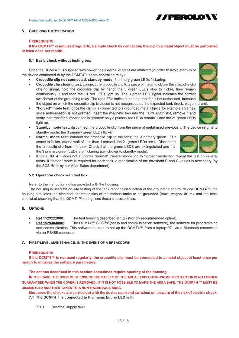
Crocodile clip not connected, standby mode: 3 primary green LEDs flickering. Crocodile clip closing test: connect the crocodile clip to a piece of metal to obtain the crocodile clip
closing signal, hold the crocodile clip by hand; the 3 green LEDs stop to flicker, they remain continuously lit and then the 21 red LEDs light up. The 3 green LED signal indicates the correct switchover of the grounding relay. The red LEDs indicate that the transfer is not authorised, because the object on which the crocodile clip is closed is not recognised as the expected tank (truck, wagon, drum).
"Forced" mode test: once the clamp is connected to a grounded metal object (for example a frame), since authorisation is not granted, insert the magnetic key into the "BYPASS" slot, remove it and verify that transfer authorisation is granted: only 3 primary red LEDs remain lit and the 21 green LEDs light up.
Standby mode test: disconnect the crocodile clip from the piece of metal used previously. The device returns to standby mode; the 3 primary green LEDs flicker.
Normal mode test: connect the crocodile clip to the tank; the 3 primary green LEDs cease to flicker, after a wait of less than 1 second, the 21 green LEDs are lit. Disconnect the crocodile clip from the tank. Check that the green LEDS are extinguished and that the 3 primary green LEDs are flickering (switchover to standby mode).
If the DCMT4 does not authorise "normal" transfer mode, go to "forced" mode and repeat the test on several tanks. If "forced" mode is required for each tank, a modification of the threshold R and C values is necessary (by the SCS(§8) or by our After-Sales department).
5.2 Operation check with test box
Refer to the instruction notice provided with the housing. The housing is used for on-site testing of the tank recognition function of the grounding control device DCMT4: the
housing simulates the electrical characteristics of the various tanks to be grounded (truck, wagon, drum), and the tests consist of checking that the DCMT4 recognises these characteristics.
6. OPTIONS
Ref 1529222000: The test housing described in 5.2 (strongly recommended option). Ref 1529404000: The DCMT4 SCS(§8) (setup and communication software), the software for programming
and communication. This software is used to set up the DCMT4 from a laptop PC, via a Bluetooth connection via an RS485 connection.
7. FIRST-LEVEL MAINTENANCE: IN THE EVENT OF A BREAKDOWN
PREREQUISITE: If the DCMT4 is not used regularly, the crocodile clip must be connected to a metal object at least once per
month to initialize the software parameters.
The actions described in this section sometimes require opening of the housing.
IN THIS CASE, THE USER MUST ENSURE THE SAFETY OF THE AREA ; EXPLOSION-PROOF PROTECTION IS NO LONGER
GUARANTEED WHEN THE COVER IS REMOVED. IF IT IS NOT POSSIBLE TO MAKE THE AREA SAFE, THE DCMT4 MUST BE
DISMANTLED AND THEN TAKEN TO A NON-HAZARDOUS AREA. Moreover, the checks are carried out with the device open and switched on: beware of the risk of electric shock. 7.1 The DCMT4 is connected to the mains but no LED is lit
7.1.1 Electrical supply fault
Instruction leaflet for DCMT4 PWA1529400000/Rev.8
14 / 15
Dismantle the cover. Check for the presence of a voltage at the electrical supply terminals. If the voltage is present at the input, the faults arises from the mains supply protection fuse F1 or F2 (see positions and characteristics on the photograph on page 9), which must be changed.
7.1.2 If the fault persists After changing the fuses, consult our Customer Service to return the board.
7.2 The crocodile clip is connected to the tank but transfer authorisation is not granted
7.2.1 The 3 primary green LEDs no longer flicker and the 21 red LEDs are lit. Ensure the correct sequence of operations: connection of the crocodile clip and then connection of the mechanical
interfaces. Repeat the cycle in the correct order. The electrical characteristics of the tank are outside the window of programmed parameters: use the SCS(§8) to
read the R and C values measured by the DCMT4. Edit the threshold R and C values to adapt the threshold window to the values measured on site. This configuration will be carried out either by an advanced user with the SCS(§8) or by contacting our After-Sales department. While waiting for the settings to be modified, operation can continue using "BYPASS" mode.
If the problem persists in "BYPASS" mode: editing of the R and C threshold settings is again required, but this time for the 'BYPASS' mode. Widen the authorisation window for R and C using the SCS(§8) or contact the After-Sales department.
PROGRAMMING BY THE SCS(§8) REQUIRES THE USE OF AN ATEX PC OR SECURING OF THE AREA WHERE THE
DCMT4 IS INSTALLED. OTHERWISE, REMOVE THE DCMT4 FROM THE AREA IN ORDER TO PERFORM PROGRAMMING
IN AN AREA WHERE THE PC CAN BE USED WITHOUT RISK.
7.2.2 The 3 green LEDs continue to flicker and the grounding relays do not switch sides Failure of the connecting cable or crocodile clip: dismantle the DCMT4 from the hazardous area and test outside
of the area. Dismantle the cover, disconnect the 2 inputs of the crocodile clip cable from their terminals, switch on, connect the 2 terminals with a conductor; if the 3 green LEDs cease to flicker, the fault is with the connecting cable or the crocodile clip. Change the cable or crocodile clip (§2).
Otherwise, the card is at fault : consult our Customer Service to return the board.
7.3 No signal on the output of the servo-control relay
Verification and possible replacement of the protection fuse of the relay, F3 or F4 defective (see picture, page 9). If the failure persists, consult our Customer Service to return the board.
7.4 Flashing of the red LEDs (alarm mode)
DO NOT CONNECT THE CROCODILE CLIP TO THE TANK IF THE RED LEDS ARE FLASHING OR FLICKERING.
The correct operation of the grounding relay is tested continuously. Failure of the contacts may lead to a hazardous situation. If the contacts of a grounding relay become "stuck", and if no signal indicates the failure, there is a risk of sparks between the crocodile clip and the tank when the crocodile clip connection is made.
The DCMT4 alarm mode thus flashes the red LEDs to indicate a failure of the groudning relay or the servo-control relay; stop the transfer operations.
Alarm definition : Blocking alarm (1 case) : The two relays are blocked No blocking alarm ( 5 cases) :
One relay is blocked Faulty output relay Faulty test capacity Clamp connected more than 4h False alarm (e.g. clamp connected on cable gland)
7.4.1 Disconnect the crocodile clip from the tank and perform a "RESET". Install the clip on insulated pin
Instruction leaflet for DCMT4 PWA1529400000/Rev.8
15 / 15
Insert the magnetic key in the "RESET" slot. (3 primary green light should flash) Connect crocodile clip on frame. If after the RESET, the unit returns to normal mode, connect the clamp on the frame during 3s to make sure the
DCMT4 is not blocking alarm. It is an no blocking alarm (faulty card or DCMT4 no used for a long time) If the DCMT4 goes again into alarm mode, to do the test on the frame again. If there is still the alarm, the board has a real and should be repaired.
7.4.2 If the problem persists with flickering red LEDs Consult our Customer Service to return the board. Or reload the program into the device (see software leaflet §10)
7.4.3 If the problem persists after reloading the program into the DCMT4 : Blocking alarm Consult our Customer Service to return the board.
7.5 Verification of the device resistance
Use an ohmmeter to annually check the resistance measured between the block of the grounded tank and the earth rod via the DCMT4.
This measurement enables you to check that: the grounding relays of the DCMT4 are operating, and the cable is not damaged. The resistance value should be less than 5.
7.6 Loss of time on the SCS(§8)
The time specified during use of the SCS has returned to zero; this indicates that the battery of the memory is empty. The DCMT4 will continue to function correctly. Consult our Customer Service to return the board to the manufacturer when necessary.
8. ADVANCED USE, PARAMETER SETTING
The original settings programmed in the DCMT4 can be edited by the user to adapt the device to the conditions of the site and of the tanks. The programming instructions are provided with the accessories used for programming:
Ref 1529404000: The DCMT4 SCS (setup and communication software), the software for programming and communication, is used to set up the DCMT4 from a laptop PC, via a Bluetooth connection or by an RS485 connection. This option allows you to:
Read the measured capacitance and resistance in real-time, Set the capacitance and resistance range in order to adapt them to the site, Recover the events that have occurred during use of the DCMT4: such as crocodile clip connections
(dates and times of connection), use the "BYPASS" mode, diagnose faults, and read the resistances and capacitances of the connected tank.
THIS TYPE OF PROGRAMMING REQUIRES EITHER THE USE OF AN ATEX PC OR
RENDERING SAFE THE AREA WHERE THE DCMT4 IS INSTALLED. OTHERWISE, MOVE THE DCMT4 TO AN
AREA WHERE THE PC CAN BE USED WITHOUT RISK.

Gebrauchsanweisung DCMT4™ PWD1529400000 / Rev.8
1 / 15
GEBRAUCHSANWEISUNG
Inbetriebnahme und Wartung
Digitales Erdungs- und Erdungskontrollgerät
DCMT4™
8 05/03/21 J. FORTIN P. SURMAN M. LEGRAND Couleur des connecteurs non
ATEX et consignes ESD
2 06/07/17
C. GODON
A. SURGET
P. SURMAN
Mise à jour nouvelle directive 201/34/UE et plaque
1 03/02/17 C. GODON J. DELLARAGIONE P. SURMAN Ajout IPX6 et IPX7, mise à
jour pour SIL2
Version Datum Erstellt Geprüft Genehmigt Gegenstand
PEROLO SAS 69 rue des Maçons Tel.: 33(0) 5 57 42 67 00 33390 BLAYE Fax: 33(0) 5 57 42 67 01 Frankreich E-Mail: [email protected] Internet: www.perolo.com
Gebrauchsanweisung DCMT4™ PWD1529400000 / Rev.8
2 / 15
INHALT
1. FUNKTIONEN UND BESCHREIBUNG DES DCMT4™ 3
1.1 VERWENDUNGSBEDINGUNGEN HINSICHTLICH DER ZÜNDSCHUTZART 3
1.2 FUNKTIONEN DES DCMT4™ 3
1.3 BESCHREIBUNG DES GERÄTS 3
1.4 KENNZEICHNUNG 5
2. FUNKTIONSPRINZIP BEI NORMALEM UND ERZWUNGENEM BETRIEB 6
2.1 GRUNDPRINZIP 6
2.2 PRINZIP DER ERKENNUNG DES TANKS 7
2.3 FREIGABE DES TRANSFERS 7
2.4 FUNKTIONSZYKLUS BEI „NORMALEM“ BETRIEB 7
2.5 FUNKTIONSZYKLUS BEI „ERZWUNGENEM“ ODER „BYPASS“-BETRIEB 8
3. KONFIGURATIONEN LKW, WAGGON, FASS 9
3.1 IM WERK VOREINGESTELLTE PARAMETER 9
3.2 WESENTLICHE PROGRAMMIERTE PARAMETER 9
3.3 FUNKTIONSBEREICH DES GERÄTS 9
4. INSTALLATION DES DCMT4™ 9
5. ÜBERPRÜFUNG DER FUNKTIONSWEISE 13
5.1 GRUNDLEGENDE ÜBERPRÜFUNG OHNE TESTBOX 13
5.2 ÜBERPRÜFUNG DER FUNKTIONSWEISE MIT DER TESTBOX 13
6. OPTIONEN 13
7. WARTUNG ERSTER STUFE, MÖGLICHE PANNEN 13
7.1 DAS DCMT4™ IST AN DER NETZSPANNUNG ANGESCHLOSSEN UND KEINE LED LEUCHTET. 14
7.2 DIE ERDUNGSKLEMME IST AM TANK ANGESCHLOSSEN, JEDOCH WIRD DIE FREIGABE DES TRANSFERS NICHT GEWÄHRT. 14
7.3 KEIN SIGNAL AM AUSGANG DES PILOTRELAIS 14
7.4 BLINKEN DER ROTEN LEDS (ALARMMODUS) 14
7.5 ÜBERPRÜFUNG DES WIDERSTANDS DER VORRICHTUNG 15
7.6 VERLUST DER UHRZEIT DER SOFTWARE SCS(ABSCHNITT 8) 15
8. FORTGESCHRITTENE VERWENDUNG, EINSTELLBARE PARAMETER 15
Gebrauchsanweisung DCMT4™ PWD1529400000 / Rev.8
3 / 15
1. FUNKTIONEN UND BESCHREIBUNG DES DCMT4™ 1.1 Verwendungsbedingungen hinsichtlich der Zündschu tzart Umgebungstemperatur beim Einsatz -40°C bis +70°C. Empfohlene Umgebungstemperatur beim Einsatz -40°C bis +50°C.
Das Gerät ist nach der ATEX-Richtlinie 2014/34/UE als der Kennzeichnung εx II 2 (1) / 1GD entsprechend zertifiziert.
Diese Kennzeichnung bedeutet: - Bei Gefährdung durch Stäube ist die Box in den Zonen 21 und 22 und die Erdungsklemme in den Zonen
20, 21 und 22 einsetzbar. - Bei Gefährdung durch Gase ist die Box in den Zonen 1 und 2 und die Erdungsklemme in den Zonen 0,
1 und 2 einsetzbar. 1.2 Funktionen des DCMT4™ Hauptsächliche Aufgabe des Sicherheitssystems DCMT4™ ist die Sicherstellung der korrekten Erdung und die
Kontrolle der Wirksamkeit der Erdung beim Transfer gefährlicher Medien aus einem Tank oder in einen solchen (Füllen und Leeren).
Bei solchen Arbeiten müssen jegliche Funken zwischen Tank und Verbindungsschnittstelle vermieden und die durch
Reibung des übertragenen Mediums an der Tankwand entstehende statische elektrische Aufladungen abgeleitet werden. Hierzu muss der Tank vor dem Anschluss der Schnittstellen geerdet werden und diese Erdungsverbindung ist dann
während des Füllens oder Leerens laufend zu überwachen. Im Gerät sind zusätzlichen Funktionen integriert: Unterscheidung zwischen einem Tank und einem anderen Gegenstand, ununterbrochene Überprüfung der richtigen Funktion der beiden Erdungsrelais für den Fall eines internen Fehlers, Anpassung des Geräts an die Bedingungen des Standorts durch Einstellung von Erkennungsparametern, Aufzeichnen und Auslesen der Maßnahmen des Bedieners. Diese Funktionen werden in den folgenden Abschnitten im Einzelnen beschrieben. 1.3 Beschreibung des Geräts Das DCMT4™ umfasst: 1 zweiteiliges Aluminiumgehäuse (AlSi7Mg06), bestehend aus dem eigentlichen Gehäuse und dem an diesem mit
8 Schrauben befestigten Deckel, in dem ein Sichtfenster aus gehärtetem Kalk-Natronsilikatglas eingearbeitet ist. Diese Baugruppe bildet die explosionsgeschützte Kapselung.
1 am Gehäuse befestigtes Elektronikmodul enthält die Versorgung, die 2 Erdungsrelais, das Pilotrelais, die Kontrollschaltungen des Schließens der Erdungsklemme und des richtigen Zustands der Erdungsrelais, die Messkreise für Widerstand und Kapazität, den die Einheit steuernden Mikroprozessor, die LEDs, die eine Freigabe oder ein Verbot des Füllens oder Leerens anzeigen .
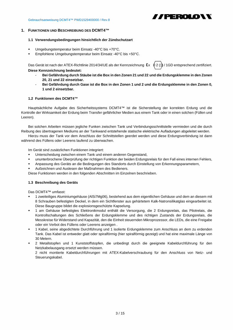
1 Kabel, seine abgedichtete Durchführung und 1 isolierte Erdungsklemme zum Anschluss an dem zu erdenden Tank. Das Kabel ist entweder glatt oder spiralförmig (hier spiralförmig gezeigt) und hat eine maximale Länge von 30 Metern.
2 Metallstopfen und 1 Kunststoffstopfen, die unbedingt durch die geeignete Kabeldurchführung für den Netzkabelausgang ersetzt werden müssen. 2 nicht montierte Kabeldurchführungen mit ATEX-Kabelverschraubung für den Anschluss von Netz- und Steuerungskabel.
Gebrauchsanweisung DCMT4™ PWD1529400000 / Rev.8
4 / 15
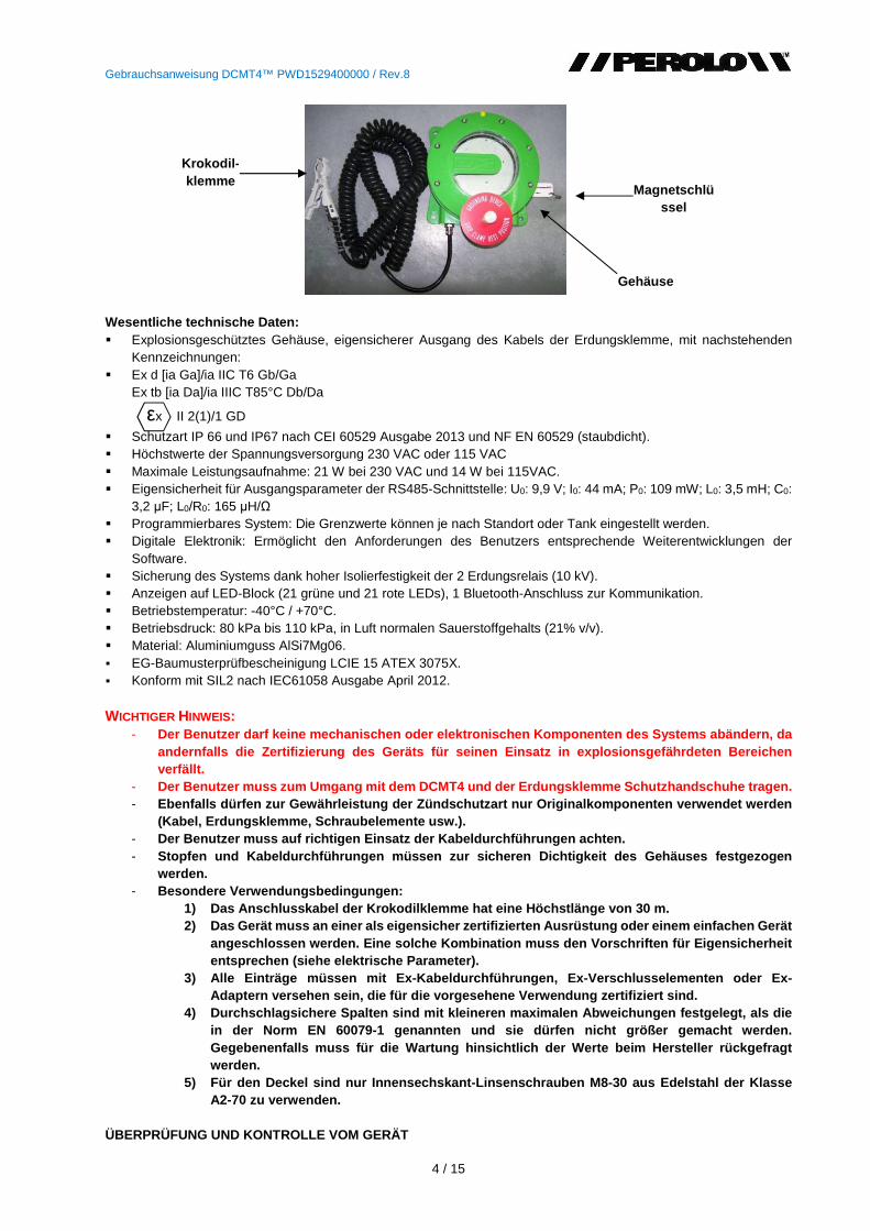
Wesentliche technische Daten: Explosionsgeschütztes Gehäuse, eigensicherer Ausgang des Kabels der Erdungsklemme, mit nachstehenden
Kennzeichnungen: Ex d [ia Ga]/ia IIC T6 Gb/Ga
Ex tb [ia Da]/ia IIIC T85°C Db/Da
εx II 2(1)/1 GD
Schutzart IP 66 und IP67 nach CEI 60529 Ausgabe 2013 und NF EN 60529 (staubdicht). Höchstwerte der Spannungsversorgung 230 VAC oder 115 VAC Maximale Leistungsaufnahme: 21 W bei 230 VAC und 14 W bei 115VAC. Eigensicherheit für Ausgangsparameter der RS485-Schnittstelle: U0: 9,9 V; I0: 44 mA; P0: 109 mW; L0: 3,5 mH; C0:
3,2 μF; L0/R0: 165 μH/Ω Programmierbares System: Die Grenzwerte können je nach Standort oder Tank eingestellt werden. Digitale Elektronik: Ermöglicht den Anforderungen des Benutzers entsprechende Weiterentwicklungen der
Software. Sicherung des Systems dank hoher Isolierfestigkeit der 2 Erdungsrelais (10 kV). Anzeigen auf LED-Block (21 grüne und 21 rote LEDs), 1 Bluetooth-Anschluss zur Kommunikation. Betriebstemperatur: -40°C / +70°C. Betriebsdruck: 80 kPa bis 110 kPa, in Luft normalen Sauerstoffgehalts (21% v/v). Material: Aluminiumguss AlSi7Mg06. EG-Baumusterprüfbescheinigung LCIE 15 ATEX 3075X. Konform mit SIL2 nach IEC61058 Ausgabe April 2012. WICHTIGER HINWEIS:
- Der Benutzer darf keine mechanischen oder elektroni schen Komponenten des Systems abändern, da andernfalls die Zertifizierung des Geräts für seine n Einsatz in explosionsgefährdeten Bereichen verfällt.
- Der Benutzer muss zum Umgang mit dem DCMT4 und der Erdungsklemme Schutzhandschuhe tragen. - Ebenfalls dürfen zur Gewährleistung der Zündschutzar t nur Originalkomponenten verwendet werden
(Kabel, Erdungsklemme, Schraubelemente usw.). - Der Benutzer muss auf richtigen Einsatz der Kabeldur chführungen achten. - Stopfen und Kabeldurchführungen müssen zur sicheren Dichtigkeit des Gehäuses festgezogen
werden. - Besondere Verwendungsbedingungen:
1) Das Anschlusskabel der Krokodilklemme hat eine H öchstlänge von 30 m. 2) Das Gerät muss an einer als eigensicher zertifiz ierten Ausrüstung oder einem einfachen Gerät
angeschlossen werden. Eine solche Kombination muss den Vorschriften für Eigensicherheit entsprechen (siehe elektrische Parameter).
3) Alle Einträge müssen mit Ex-Kabeldurchführungen, Ex -Verschlusselementen oder Ex-Adaptern versehen sein, die für die vorgesehene Ver wendung zertifiziert sind.
4) Durchschlagsichere Spalten sind mit kleineren max imalen Abweichungen festgelegt, als die in der Norm EN 60079-1 genannten und sie dürfen nich t größer gemacht werden. Gegebenenfalls muss für die Wartung hinsichtlich de r Werte beim Hersteller rückgefragt werden.
5) Für den Deckel sind nur Innensechskant-Linsensch rauben M8-30 aus Edelstahl der Klasse A2-70 zu verwenden.
ÜBERPRÜFUNG UND KONTROLLE VOM GERÄT
Magnetschlüssel
Gehäuse
Krokodil - klemme
Gebrauchsanweisung DCMT4™ PWD1529400000 / Rev.8
5 / 15
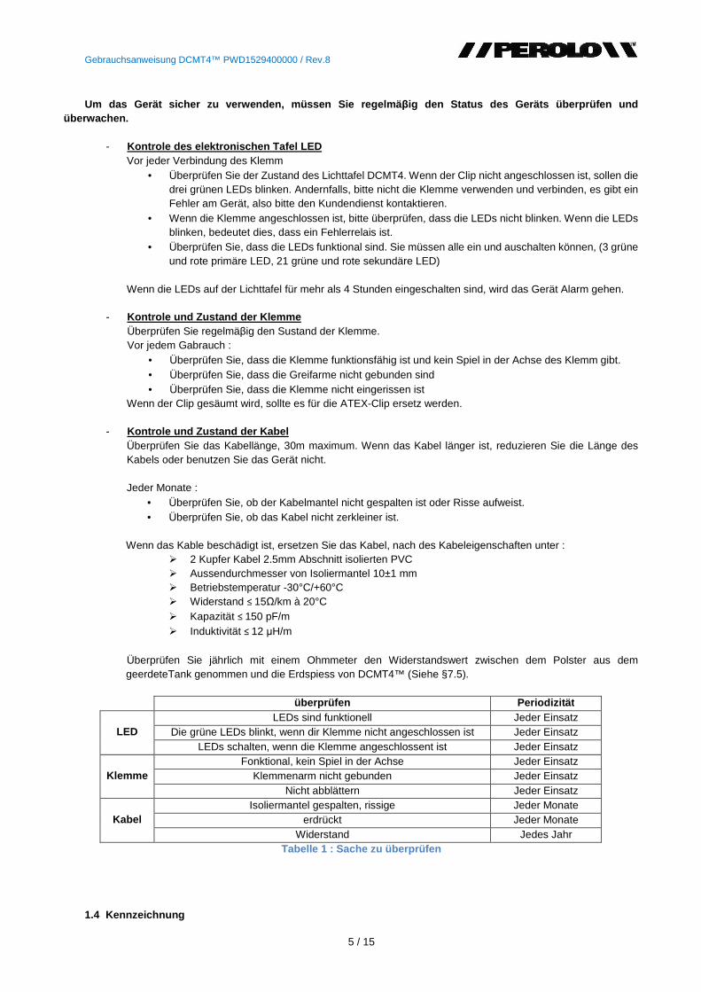
Um das Gerät sicher zu verwenden, müssen Sie regelmä βig den Status des Geräts überprüfen und
überwachen.
- Kontrole des elektronischen Tafel LED Vor jeder Verbindung des Klemm
• Überprüfen Sie der Zustand des Lichttafel DCMT4. Wenn der Clip nicht angeschlossen ist, sollen die drei grünen LEDs blinken. Andernfalls, bitte nicht die Klemme verwenden und verbinden, es gibt ein Fehler am Gerät, also bitte den Kundendienst kontaktieren.
• Wenn die Klemme angeschlossen ist, bitte überprüfen, dass die LEDs nicht blinken. Wenn die LEDs blinken, bedeutet dies, dass ein Fehlerrelais ist.
• Überprüfen Sie, dass die LEDs funktional sind. Sie müssen alle ein und auschalten können, (3 grüne und rote primäre LED, 21 grüne und rote sekundäre LED)
Wenn die LEDs auf der Lichttafel für mehr als 4 Stunden eingeschalten sind, wird das Gerät Alarm gehen.
- Kontrole und Zustand der Klemme Überprüfen Sie regelmäβig den Sustand der Klemme. Vor jedem Gabrauch :
• Überprüfen Sie, dass die Klemme funktionsfähig ist und kein Spiel in der Achse des Klemm gibt. • Überprüfen Sie, dass die Greifarme nicht gebunden sind • Überprüfen Sie, dass die Klemme nicht eingerissen ist
Wenn der Clip gesäumt wird, sollte es für die ATEX-Clip ersetz werden.
- Kontrole und Zustand der Kabel Überprüfen Sie das Kabellänge, 30m maximum. Wenn das Kabel länger ist, reduzieren Sie die Länge des Kabels oder benutzen Sie das Gerät nicht.
Jeder Monate :
• Überprüfen Sie, ob der Kabelmantel nicht gespalten ist oder Risse aufweist. • Überprüfen Sie, ob das Kabel nicht zerkleiner ist.
Wenn das Kable beschädigt ist, ersetzen Sie das Kabel, nach des Kabeleigenschaften unter : 2 Kupfer Kabel 2.5mm Abschnitt isolierten PVC Aussendurchmesser von Isoliermantel 10±1 mm Betriebstemperatur -30°C/+60°C Widerstand ≤ 15Ω/km à 20°C Kapazität ≤ 150 pF/m Induktivität ≤ 12 μH/m
Überprüfen Sie jährlich mit einem Ohmmeter den Widerstandswert zwischen dem Polster aus dem geerdeteTank genommen und die Erdspiess von DCMT4™ (Siehe §7.5). überprüfen Periodizität
LED LEDs sind funktionell Jeder Einsatz
Die grüne LEDs blinkt, wenn dir Klemme nicht angeschlossen ist Jeder Einsatz LEDs schalten, wenn die Klemme angeschlossent ist Jeder Einsatz
Klemme Fonktional, kein Spiel in der Achse Jeder Einsatz
Klemmenarm nicht gebunden Jeder Einsatz Nicht abblättern Jeder Einsatz
Kabel Isoliermantel gespalten, rissige Jeder Monate
erdrückt Jeder Monate Widerstand Jedes Jahr
Tabelle 1 : Sache zu überprüfen
1.4 Kennzeichnung
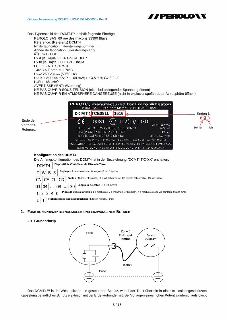
Gebrauchsanweisung DCMT4™ PWD1529400000 / Rev.8
6 / 15
Das Typenschild des DCMT4™ enthält folgende Einträge.
PEROLO SAS 69 rue des maçons 33390 Blaye Référence: (Referenz) DCMT4 N° de fabrication: (Herstellungsnummer) … Année de fabrication: (Herstellungsjahr) … εx II 2(1)/1 GD Ex d [ia Ga]/ia IIC T6 Gb/Ga IP67 Ex tb [ia Da]/ia IIIC T85°C Db/Da LCIE 15 ATEX 3075 X - 40°C ≤ T amb ≤ + 70°C Umax: 250 Vefficace (50/60 Hz) Uo: 9,9 V; Io: 44 mA; Po: 109 mW; Lo: 3,5 mH; Co: 3,2 μF Lo/Ro: 165 μH/Ω AVERTISSEMENT: (Warnung) NE PAS OUVRIR SOUS TENSION (nicht bei anliegender Spannung öffnen) NE PAS OUVRIR EN ATMOSPHERE DANGEREUSE (nicht in explosionsgefährdeter Atmosphäre öffnen)
Konfiguration des DCMT4 Die Anfangskonfiguration des DCMT4 ist in der Bezeichnung "DCMT4TXXXX“ enthalten.
2. FUNKTIONSPRINZIP BEI NORMALEM UND ERZWUNGENEM BETRIEB 2.1 Grundprinzip
Das DCMT4™ ist im Wesentlichen ein gesteuertes Schütz, wobei der Tank über ein in einer explosionsgeschützten
Kapselung befindliches Schütz elektrisch mit der Erde verbunden ist. Bei Vorliegen eines hohen Potentialunterschieds bleibt
Zone 1 DCMT4™
Tank
Zone 0 Erdungsk
lemme
Kabel
Erde
Ende der Vertriebs-Referenz
TCE081L 1516 Serien-Nr. 1516
Zeit-Nr. Jahr
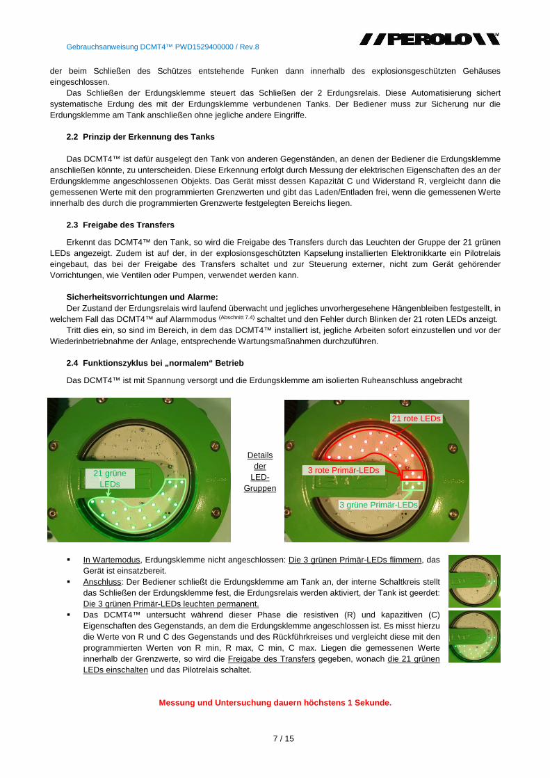
Gebrauchsanweisung DCMT4™ PWD1529400000 / Rev.8
7 / 15
der beim Schließen des Schützes entstehende Funken dann innerhalb des explosionsgeschützten Gehäuses eingeschlossen.
Das Schließen der Erdungsklemme steuert das Schließen der 2 Erdungsrelais. Diese Automatisierung sichert systematische Erdung des mit der Erdungsklemme verbundenen Tanks. Der Bediener muss zur Sicherung nur die Erdungsklemme am Tank anschließen ohne jegliche andere Eingriffe.
2.2 Prinzip der Erkennung des Tanks Das DCMT4™ ist dafür ausgelegt den Tank von anderen Gegenständen, an denen der Bediener die Erdungsklemme
anschließen könnte, zu unterscheiden. Diese Erkennung erfolgt durch Messung der elektrischen Eigenschaften des an der Erdungsklemme angeschlossenen Objekts. Das Gerät misst dessen Kapazität C und Widerstand R, vergleicht dann die gemessenen Werte mit den programmierten Grenzwerten und gibt das Laden/Entladen frei, wenn die gemessenen Werte innerhalb des durch die programmierten Grenzwerte festgelegten Bereichs liegen.
2.3 Freigabe des Transfers
Erkennt das DCMT4™ den Tank, so wird die Freigabe des Transfers durch das Leuchten der Gruppe der 21 grünen LEDs angezeigt. Zudem ist auf der, in der explosionsgeschützten Kapselung installierten Elektronikkarte ein Pilotrelais eingebaut, das bei der Freigabe des Transfers schaltet und zur Steuerung externer, nicht zum Gerät gehörender Vorrichtungen, wie Ventilen oder Pumpen, verwendet werden kann.
Sicherheitsvorrichtungen und Alarme: Der Zustand der Erdungsrelais wird laufend überwacht und jegliches unvorhergesehene Hängenbleiben festgestellt, in
welchem Fall das DCMT4™ auf Alarmmodus (Abschnitt 7.4) schaltet und den Fehler durch Blinken der 21 roten LEDs anzeigt. Tritt dies ein, so sind im Bereich, in dem das DCMT4™ installiert ist, jegliche Arbeiten sofort einzustellen und vor der
Wiederinbetriebnahme der Anlage, entsprechende Wartungsmaßnahmen durchzuführen. 2.4 Funktionszyklus bei „normalem“ Betrieb
Das DCMT4™ ist mit Spannung versorgt und die Erdungsklemme am isolierten Ruheanschluss angebracht
In Wartemodus, Erdungsklemme nicht angeschlossen: Die 3 grünen Primär-LEDs flimmern, das
Gerät ist einsatzbereit. Anschluss: Der Bediener schließt die Erdungsklemme am Tank an, der interne Schaltkreis stellt
das Schließen der Erdungsklemme fest, die Erdungsrelais werden aktiviert, der Tank ist geerdet: Die 3 grünen Primär-LEDs leuchten permanent.
Das DCMT4™ untersucht während dieser Phase die resistiven (R) und kapazitiven (C) Eigenschaften des Gegenstands, an dem die Erdungsklemme angeschlossen ist. Es misst hierzu die Werte von R und C des Gegenstands und des Rückführkreises und vergleicht diese mit den programmierten Werten von R min, R max, C min, C max. Liegen die gemessenen Werte innerhalb der Grenzwerte, so wird die Freigabe des Transfers gegeben, wonach die 21 grünen LEDs einschalten und das Pilotrelais schaltet.
Messung und Untersuchung dauern höchstens 1 Sekunde.
21 grüne LEDs
3 grüne Primär-LEDs
3 rote Primär-LEDs
21 rote LEDs
Details
der LED-
Gruppen
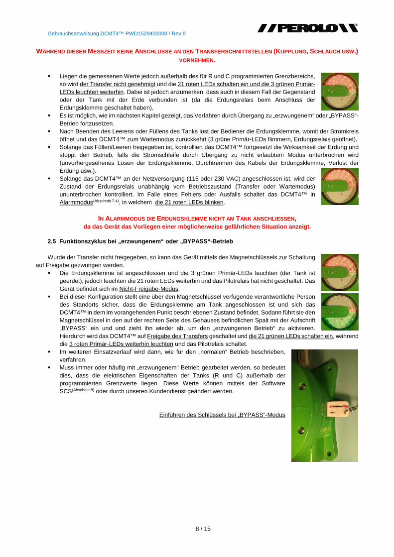
Gebrauchsanweisung DCMT4™ PWD1529400000 / Rev.8
8 / 15
WÄHREND DIESER MESSZEIT KEINE ANSCHLÜSSE AN DEN TRANSFERSCHNITTSTELLEN (KUPPLUNG, SCHLAUCH USW .) VORNEHMEN.
Liegen die gemessenen Werte jedoch außerhalb des für R und C programmierten Grenzbereichs,
so wird der Transfer nicht genehmigt und die 21 roten LEDs schalten ein und die 3 grünen Primär-LEDs leuchten weiterhin. Dabei ist jedoch anzumerken, dass auch in diesem Fall der Gegenstand oder der Tank mit der Erde verbunden ist (da die Erdungsrelais beim Anschluss der Erdungsklemme geschaltet haben).
Es ist möglich, wie im nächsten Kapitel gezeigt, das Verfahren durch Übergang zu „erzwungenem“ oder „BYPASS“-Betrieb fortzusetzen.
Nach Beenden des Leerens oder Füllens des Tanks löst der Bediener die Erdungsklemme, womit der Stromkreis öffnet und das DCMT4™ zum Wartemodus zurückkehrt (3 grüne Primär-LEDs flimmern, Erdungsrelais geöffnet).
Solange das Füllen/Leeren freigegeben ist, kontrolliert das DCMT4™ fortgesetzt die Wirksamkeit der Erdung und stoppt den Betrieb, falls die Stromschleife durch Übergang zu nicht erlaubtem Modus unterbrochen wird (unvorhergesehenes Lösen der Erdungsklemme, Durchtrennen des Kabels der Erdungsklemme, Verlust der Erdung usw.).
Solange das DCMT4™ an der Netzversorgung (115 oder 230 VAC) angeschlossen ist, wird der Zustand der Erdungsrelais unabhängig vom Betriebszustand (Transfer oder Wartemodus) ununterbrochen kontrolliert. Im Falle eines Fehlers oder Ausfalls schaltet das DCMT4™ in Alarmmodus(Abschnitt 7.4), in welchem die 21 roten LEDs blinken.
IN ALARMMODUS DIE ERDUNGSKLEMME NICHT AM TANK ANSCHLIESSEN ,
da das Gerät das Vorliegen einer möglicherweise gefä hrlichen Situation anzeigt.
2.5 Funktionszyklus bei „erzwungenem“ oder „BYPASS“-Bet rieb Wurde der Transfer nicht freigegeben, so kann das Gerät mittels des Magnetschlüssels zur Schaltung
auf Freigabe gezwungen werden. Die Erdungsklemme ist angeschlossen und die 3 grünen Primär-LEDs leuchten (der Tank ist
geerdet), jedoch leuchten die 21 roten LEDs weiterhin und das Pilotrelais hat nicht geschaltet. Das Gerät befindet sich im Nicht-Freigabe-Modus.
Bei dieser Konfiguration stellt eine über den Magnetschlüssel verfügende verantwortliche Person des Standorts sicher, dass die Erdungsklemme am Tank angeschlossen ist und sich das DCMT4™ in dem im vorangehenden Punkt beschriebenen Zustand befindet. Sodann führt sie den Magnetschlüssel in den auf der rechten Seite des Gehäuses befindlichen Spalt mit der Aufschrift „BYPASS“ ein und und zieht ihn wieder ab, um den „erzwungenen Betrieb“ zu aktivieren. Hierdurch wird das DCMT4™ auf Freigabe des Transfers geschaltet und die 21 grünen LEDs schalten ein, während die 3 roten Primär-LEDs weiterhin leuchten und das Pilotrelais schaltet.
Im weiteren Einsatzverlauf wird dann, wie für den „normalen“ Betrieb beschrieben, verfahren.
Muss immer oder häufig mit „erzwungenem“ Betrieb gearbeitet werden, so bedeutet dies, dass die elektrischen Eigenschaften der Tanks (R und C) außerhalb der programmierten Grenzwerte liegen. Diese Werte können mittels der Software SCS(Abschnitt 8) oder durch unseren Kundendienst geändert werden.
Einführen des Schlüssels bei „BYPASS“-Modus
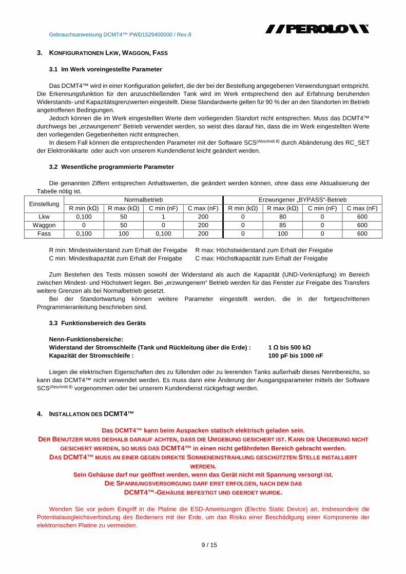
Gebrauchsanweisung DCMT4™ PWD1529400000 / Rev.8
9 / 15
3. KONFIGURATIONEN LKW, WAGGON, FASS 3.1 Im Werk voreingestellte Parameter Das DCMT4™ wird in einer Konfiguration geliefert, die der bei der Bestellung angegebenen Verwendungsart entspricht.
Die Erkennungsfunktion für den anzuschließenden Tank wird im Werk entsprechend den auf Erfahrung beruhenden Widerstands- und Kapazitätsgrenzwerten eingestellt. Diese Standardwerte gelten für 90 % der an den Standorten im Betrieb angetroffenen Bedingungen.
Jedoch können die im Werk eingestellten Werte dem vorliegenden Standort nicht entsprechen. Muss das DCMT4™ durchwegs bei „erzwungenem“ Betrieb verwendet werden, so weist dies darauf hin, dass die im Werk eingestellten Werte den vorliegenden Gegebenheiten nicht entsprechen.
In diesem Fall können die entsprechenden Parameter mit der Software SCS(Abschnitt 8) durch Abänderung des RC_SET der Elektronikkarte oder auch von unserem Kundendienst leicht geändert werden.
3.2 Wesentliche programmierte Parameter Die genannten Ziffern entsprechen Anhaltswerten, die geändert werden können, ohne dass eine Aktualisierung der
Tabelle nötig ist.
Einstellung Normalbetrieb Erzwungener „BYPASS“-Betrieb
R min (kΩ) R max (kΩ) C min (nF) C max (nF) R min (kΩ) R max (kΩ) C min (nF) C max (nF) Lkw 0,100 50 1 200 0 80 0 600
Waggon 0 50 0 200 0 85 0 600 Fass 0,100 100 0,100 200 0 100 0 600
R min: Mindestwiderstand zum Erhalt der Freigabe R max: Höchstwiderstand zum Erhalt der Freigabe C min: Mindestkapazität zum Erhalt der Freigabe C max: Höchstkapazität zum Erhalt der Freigabe Zum Bestehen des Tests müssen sowohl der Widerstand als auch die Kapazität (UND-Verknüpfung) im Bereich
zwischen Mindest- und Höchstwert liegen. Bei „erzwungenem“ Betrieb werden für das Fenster zur Freigabe des Transfers weitere Grenzen als bei Normalbetrieb gesetzt.
Bei der Standortwartung können weitere Parameter eingestellt werden, die in der fortgeschrittenen Programmieranleitung beschrieben sind.
3.3 Funktionsbereich des Geräts Nenn-Funktionsbereiche: Widerstand der Stromschleife (Tank und Rückleitung ü ber die Erde) : 1 Ω bis 500 kΩ Kapazität der Stromschleife : 100 pF bis 1000 nF Liegen die elektrischen Eigenschaften des zu füllenden oder zu leerenden Tanks außerhalb dieses Nennbereichs, so
kann das DCMT4™ nicht verwendet werden. Es muss dann eine Änderung der Ausgangsparameter mittels der Software SCS(Abschnitt 8) vorgenommen oder bei unserem Kundendienst rückgefragt werden.
4. INSTALLATION DES DCMT4™
Das DCMT4™ kann beim Auspacken statisch elektrisch geladen sein. DER BENUTZER MUSS DESHALB DARAUF ACHTEN , DASS DIE UMGEBUNG GESICHERT IST. KANN DIE UMGEBUNG NICHT
GESICHERT WERDEN, SO MUSS DAS DCMT4™ in einen nicht gefährdeten Bereich gebracht werden. DAS DCMT4™ MUSS AN EINER GEGEN DIREKTE SONNENEINSTRAHLUNG GESCHÜTZTEN STELLE INSTALLIERT
WERDEN. Sein Gehäuse darf nur geöffnet werden, wenn das Gerä t nicht mit Spannung versorgt ist.
DIE SPANNUNGSVERSORGUNG DARF ERST ERFOLGEN , NACH DEM DAS DCMT4™-GEHÄUSE BEFESTIGT UND GEERDET WURDE .
Wenden Sie vor jedem Eingriff in die Platine die ESD-Anweisungen (Electro Static Device) an, insbesondere die
Potentialausgleichsverbindung des Bedieners mit der Erde, um das Risiko einer Beschädigung einer Komponente der elektronischen Platine zu vermeiden.
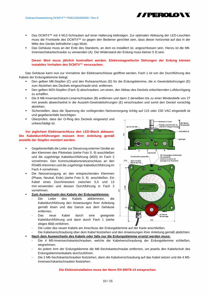
Gebrauchsanweisung DCMT4™ PWD1529400000 / Rev.8
10 / 15
Das DCMT4™ mit 4 M12-Schrauben auf einer Halterung befestigen. Zur optimalen Ablesung der LED-Leuchten
muss die Frontseite des DCMT4™ so gegen den Bediener gerichtet sein, dass dieser horizontal auf das in der Mitte des Geräts befindliche Logo blickt.
Das Gehäuse muss an der Erde des Standorts, an dem es installiert ist, angeschlossen sein. Hierzu ist die M6-Innensechskantschraube zu verwenden (A). Der Widerstand der Erdung muss kleiner 5 Ω sein. Dieser Wert muss jährlich kontrolliert werden. Elekt romagnetische Störungen der Erdung können instabiles Verhalten des DCMT4™ verursachen.
Das Gehäuse kann nun zur Vornahme der Elektroanschlüsse geöffnet werden. Fach 1 ist von der Durchführung des Kabels der Erdungsklemme belegt.
Den gelben M8-Stopfen (C) und den Ruheanschluss (D) für die Erdungsklemme, die in Gewindebohrungen (E) zum Abziehen des Deckels eingeschraubt sind, entfernen.
Den gelben M20-Stopfen (Fach 3) abschrauben, um einen, den Abbau des Deckels erleichternden Luftdurchgang zu schaffen.
Die 8 M8-Innensechskant-Linsenschrauben (B) entfernen und dann 2 derselben bis zu einer Mindesttiefe von 27 mm jeweils abwechselnd in die Auszieh-Gewindebohrungen (E) einschrauben und somit den Deckel vorsichtig abziehen.
Sicherstellen, dass die Spannung der vorliegenden Netzversorgung richtig auf 115 oder 230 VAC eingestellt ist und gegebenenfalls berichtigen.
Überprüfen, dass der O-Ring des Deckels eingesetzt und unbeschädigt ist.
Vor jeglichem Elektroanschluss den LED-Block abbauen.
Die Kabeldurchführungen müssen ihrer Anleitung gemä ß anstelle der Stopfen montiert werden.
Gegebenenfalls die Leiter zur Steuerung externer Geräte an
den Klemmen des Pilotrelais (siehe Foto S. 9) anschließen und die zugehörige Kabeldurchführung (M20) im Fach 2 vornehmen. Den Kommunikationsnetzanschluss an den RS485-Klemmen und die zugehörige Kabeldurchführung im Fach 4 vornehmen.
Die Netzversorgung an den entsprechenden Klemmen (Phase, Neutral, Erde) (siehe Foto S. 9) anschließen. Ein Kabel eines Durchmessers zwischen 5,5 und 13 mm verwenden und dessen Durchführung in Fach 3 vornehmen.
Zum Auswechseln des Kabels der Erdungsklemme: - Die Leiter des Kabels abklemmen, die
Kabeldurchführung den Anweisungen ihrer Anleitung gemäß lösen und das Ganze aus dem Gehäuse entfernen.
- Das neue Kabel durch eine geeignete Kabeldurchführung und dann durch Fach 1 (siehe obiges Bild) einführen.
- Die Leiter des neuen Kabels am Anschluss der Erdungsklemme auf der Karte anschließen. - Die Kabelverschraubung über dem Kabel festziehen und den Anweisungen ihrer Anleitung gemäß abdichten.
Nach dem Auswechseln des Kabels oder falls nur die Erdungsklemme ersetzt werden muss: - Die 4 M5-Innensechskantschrauben, welche die Kabelverschraubung der Erdungsklemme schließen,
wegnehmen. - An jedem Arm der Erdungsklemme die M6-Sechskantschraube entfernen, um jeweils den Kabelschuh des
Erdungsklemmenkabels durchzuführen. - Die 2 M6-Sechskantschrauben festziehen, dann die Kabelverschraubung auf das Kabel setzen und die 4 M5-
Innensechskantschrauben festziehen.
Die Elektroinstallation muss der Norm EN 60079-14 ent sprechen.
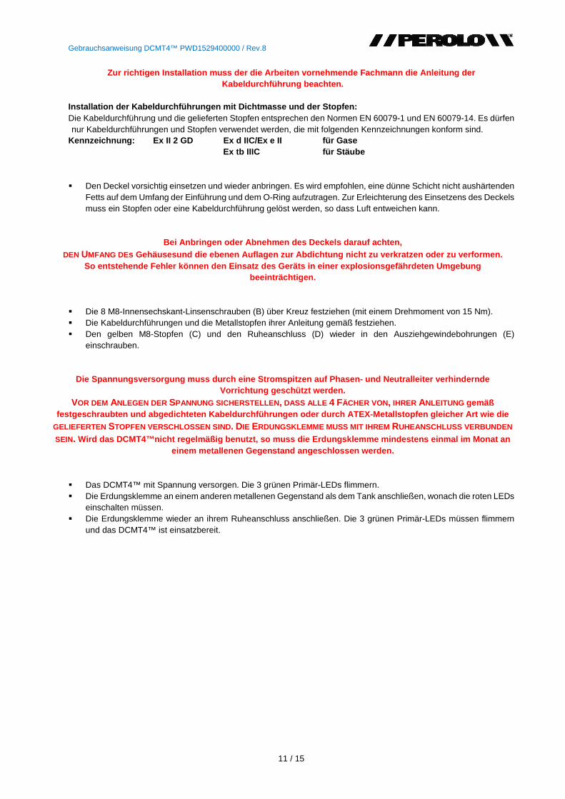
Gebrauchsanweisung DCMT4™ PWD1529400000 / Rev.8
11 / 15
Zur richtigen Installation muss der die Arbeiten vo rnehmende Fachmann die Anleitung der Kabeldurchführung beachten.
Installation der Kabeldurchführungen mit Dichtmasse und der Stopfen: Die Kabeldurchführung und die gelieferten Stopfen entsprechen den Normen EN 60079-1 und EN 60079-14. Es dürfen nur Kabeldurchführungen und Stopfen verwendet werden, die mit folgenden Kennzeichnungen konform sind.
Kennzeichnung: Ex II 2 GD Ex d IIC/Ex e II für Gase Ex tb IIIC für Stäube
Den Deckel vorsichtig einsetzen und wieder anbringen. Es wird empfohlen, eine dünne Schicht nicht aushärtenden Fetts auf dem Umfang der Einführung und dem O-Ring aufzutragen. Zur Erleichterung des Einsetzens des Deckels muss ein Stopfen oder eine Kabeldurchführung gelöst werden, so dass Luft entweichen kann.
Bei Anbringen oder Abnehmen des Deckels darauf acht en, DEN UMFANG DEs Gehäusesund die ebenen Auflagen zur Abdichtung ni cht zu verkratzen oder zu verformen.
So entstehende Fehler können den Einsatz des Geräts in einer explosionsgefährdeten Umgebung beeinträchtigen.
Die 8 M8-Innensechskant-Linsenschrauben (B) über Kreuz festziehen (mit einem Drehmoment von 15 Nm). Die Kabeldurchführungen und die Metallstopfen ihrer Anleitung gemäß festziehen. Den gelben M8-Stopfen (C) und den Ruheanschluss (D) wieder in den Ausziehgewindebohrungen (E)
einschrauben.
Die Spannungsversorgung muss durch eine Stromspitzen auf Phasen- und Neutralleiter verhindernde Vorrichtung geschützt werden.
VOR DEM ANLEGEN DER SPANNUNG SICHERSTELLEN , DASS ALLE 4 FÄCHER VON, IHRER ANLEITUNG gemäß festgeschraubten und abgedichteten Kabeldurchführun gen oder durch ATEX-Metallstopfen gleicher Art wie d ie
GELIEFERTEN STOPFEN VERSCHLOSSEN SIND. DIE ERDUNGSKLEMME MUSS MIT IHREM RUHEANSCHLUSS VERBUNDEN
SEIN. Wird das DCMT4™nicht regelmäßig benutzt, so muss d ie Erdungsklemme mindestens einmal im Monat an einem metallenen Gegenstand angeschlossen werden.
Das DCMT4™ mit Spannung versorgen. Die 3 grünen Primär-LEDs flimmern. Die Erdungsklemme an einem anderen metallenen Gegenstand als dem Tank anschließen, wonach die roten LEDs
einschalten müssen. Die Erdungsklemme wieder an ihrem Ruheanschluss anschließen. Die 3 grünen Primär-LEDs müssen flimmern
und das DCMT4™ ist einsatzbereit.
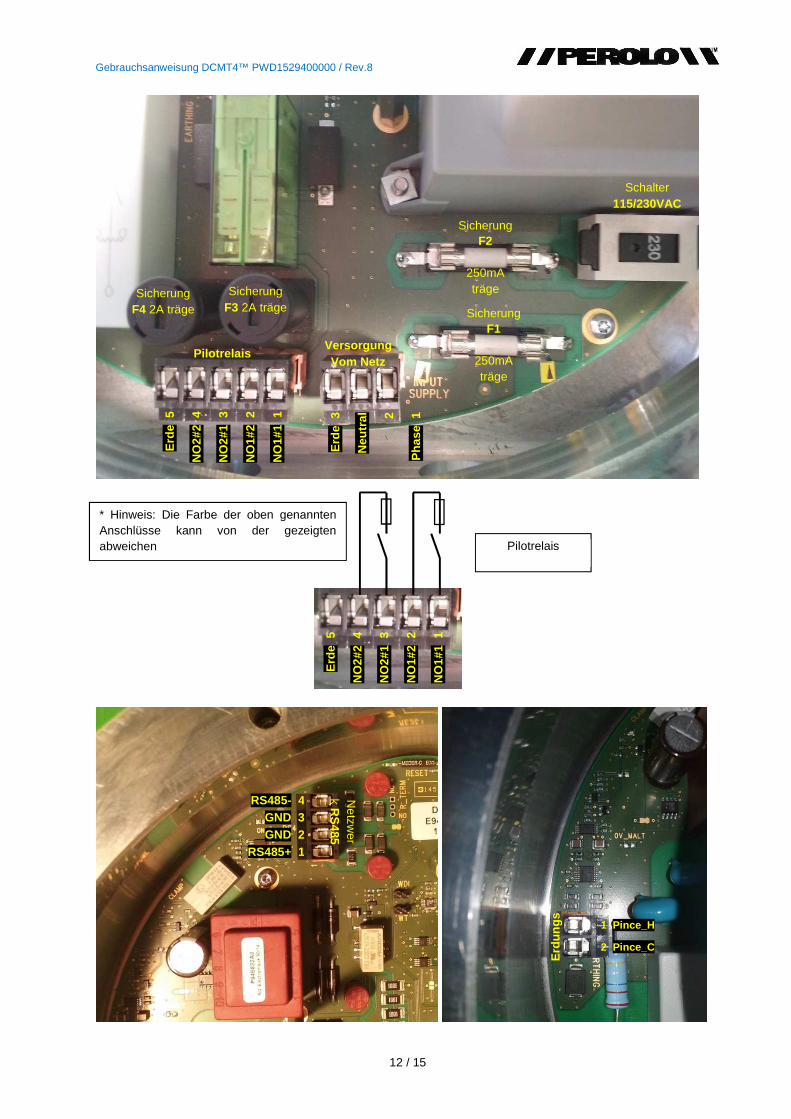
Gebrauchsanweisung DCMT4™ PWD1529400000 / Rev.8
12 / 15
Schalter 115/230VAC
Erd
e 3
Neu
tral
2
Pha
se 1
Sicherung F2
250mA träge
Sicherung F1
250mA träge
Sicherung F3 2A träge
Versorgung Vom Netz
Erd
e 5
NO
2#2
4
NO
2#1
3
NO
1#2
2
NO
1#1
1
Pilotrelais
Sicherung F4 2A träge
RS485- 4 GND 3 GND 2
RS485+ 1
Netzw
erk R
S485
1 Pince_H
2 Pince_C
Erd
ungs
Erd
e 5
NO
2#2
4
NO
2#1
3
NO
1#2
2
NO
1#1
1
Pilotrelais
* Hinweis: Die Farbe der oben genannten Anschlüsse kann von der gezeigten abweichen
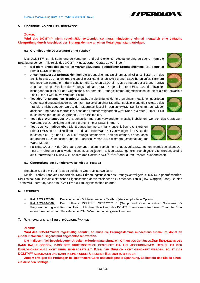
Gebrauchsanweisung DCMT4™ PWD1529400000 / Rev.8
13 / 15
5. ÜBERPRÜFUNG DER FUNKTIONSWEISE ZUVOR: Wird das DCMT4™ nicht regelmäßig verwendet, so muss mindestens einmal monatlich eine einfache
Überprüfung durch Anschluss der Erdungsklemme an ein en Metallgegenstand erfolgen. 5.1 Grundlegende Überprüfung ohne Testbox Das DCMT4™ ist mit Spannung zu versorgen und seine externen Ausgänge sind zu sperren (um die
Betätigung der vom Pilotrelais des DCMT4™ gesteuerten Geräte zu verhindern). Bei nicht angeschlossener, in Wartungszustand befin dlicher Erdungsklemme: Die 3 grünen
Primär-LEDs flimmern. Anschlusstest der Erdungsklemme: Die Erdungsklemme an einem Metallteil anschließen, um das
Schließsignal zu erhalten, und sie dabei in der Hand halten. Die 3 grünen LEDs hören auf zu flimmern und leuchten permanent, dann schalten die 21 roten LEDs ein. Das Verhalten der 3 grünen LEDs zeigt das richtige Schalten der Erdungsrelais an. Darauf zeigen die roten LEDs, dass der Transfer nicht genehmigt ist, da der Gegenstand, an dem die Erdungsklemme angeschlossen ist, nicht als der erwartete Tank erkannt wird (Lkw, Waggon, Fass).
Test des "erzwungenen" Betriebs: Nachdem die Erdungsklemme an einem metallenen geerdeten Gegenstand angeschlossen wurde (zum Beispiel an einer Metallkonstruktion) und die Freigabe des Transfers nicht gegeben wurde, den Magnetschlüssel in den „BYPASS“-Schlitz einführen, wieder abziehen und dann sicherstellen, dass der Transfer freigegeben wird: Nur die 3 roten Primär-LEDs leuchten weiter und die 21 grünen LEDs schalten ein.
Test des Wartemodus: Die Erdungsklemme vom verwendeten Metallteil abziehen, wonach das Gerät zum Wartemodus zurückkehrt und die 3 grünen Primär-LEDs flimmern.
Test des Normalbetriebs: Die Erdungsklemme am Tank anschließen, die 3 grünen Primär-LEDs hören auf zu flimmern und nach einer Wartezeit von weniger als 1 Sekunde leuchten die 21 grünen LEDs. Die Erdungsklemme vom Tank abklemmen, prüfen, dass die grünen LEDs erlöschen und die 3 grünen Primär-LEDs flimmern (Umschaltung auf Warte-Modus).
Falls das DCMT4™ den Übergang zum „normalem“ Betrieb nicht erlaubt, auf „erzwungenen“ Betrieb schalten. Den Test an mehreren Tanks wiederholen. Muss bei jedem Tank zu „erzwungenem“ Betrieb geschaltet werden, so sind die Grenzwerte für R und C zu ändern (mit Software SCS(Abschnitt 8) oder durch unseren Kundendienst).
5.2 Überprüfung der Funktionsweise mit der Testbox Beachten Sie die mit der Testbox gelieferte Gebrauchsanweisung Mit der Testbox kann am Standort die Tank-Erkennungsfunktion des Erdungskontrollgeräts DCMT4™ geprüft werden.
Die Testbox simuliert die elektrischen Eigenschaften der verschiedenen zu erdenden Tanks (Lkw, Waggon, Fass). Bei den Tests wird überprüft, dass das DCMT4™ die Tankeigenschaften erkennt.
6. OPTIONEN
Ref. 1529222000: Die in Abschnitt 5.2 beschriebene Testbox (stark empfohlene Option). Ref. 1529404000: Die Software DCMT4™ SCS(Abschnitt 8) (Setup and Communication Software) für
Programmierung und Kommunikation. Mit ihrer Hilfe kann das DCMT4™ von einem tragbaren Computer über einen Bluetooth-Controller oder eine RS485-Verbindung eingestellt werden.
7. WARTUNG ERSTER STUFE, MÖGLICHE PANNEN
ZUVOR: Wird das DCMT4™nicht regelmäßig benutzt, so muss di e Erdungsklemme mindestens einmal im Monat an
einem metallenen Gegenstand angeschlossen werden. Die in diesem Teil beschriebenen Arbeiten erfordern manchmal ein Öffnen des Gehäuses. DER BENUTZER MUSS
DANN DAFÜR SORGEN , DASS DER ARBEITSBEREICH GESICHERT IST. BEI ABGENOMMENEM DECKEL IST DER
EXPLOSIONSSCHUTZ NICHT MEHR SICHERGESTELLT . KANN DER BEREICH NICHT GESICHERT WERDEN, SO IST DAS
DCMT4™ ABZUBAUEN UND DANN IN EINEN UNGEFÄHRLICHEN BEREICH ZU BRINGEN. Zudem erfolgen die Prüfungen bei geöffnetem Gerät un d anliegender Spannung. Es besteht das Risiko eines
elektrischen Schlags.
Gebrauchsanweisung DCMT4™ PWD1529400000 / Rev.8
14 / 15
7.1 Das DCMT4™ ist an der Netzspannung angeschlosse n und keine LED leuchtet.
7.1.1 Fehler der Spannungsversorgung Den Deckel abbauen und überprüfen, dass die Spannung an den Klemmen der Spannungsversorgung anliegt. Ist die
Spannung am Eingang vorhanden, so kommt der Fehler von der Sicherung F1 oder F2 der Netzversorgung (für deren Positionen und Eigenschaften siehe Foto auf S. 9), die auszuwechseln ist.
7.1.2 Besteht der Fehler weiterhin:
Nach dem Sicherungswechsel bei unserem Kundendienst hinsichtlich der Rücksendung der Karte anfragen. 7.2 Die Erdungsklemme ist am Tank angeschlossen, jed och wird die Freigabe des Transfers nicht gewährt.
7.2.1 Die 3 grünen Primär-LEDs flimmern nicht mehr und die 21 roten LEDs leuchten Den richtigen zeitlichen Ablauf der Maßnahmen einhalten. Zuerst die Erdungsklemme anschließen, dann die
verschiedenen mechanischen Verbindungen vornehmen. Den Zyklus in der richtigen Reihenfolge wiederholen. Liegen die elektrischen Eigenschaften des Tanks außerhalb der programmierten Werte, so sind mit der Software
SCS(Abschnitt 8) die vom DCMT4™ gemessenen Widerstands- und Kapazitätswerte abzulesen und dann die Grenzwerte von R und C so zu ändern, dass der durch diese bestimmte Bereich zu den Messwerten am Standort passt. Diese Einstellung wird entweder von einem fortgeschrittenen Benutzer mit der Software SCS(Abschnitt 8) oder durch unseren Kundendienst durchgeführt. In Erwartung dieser Änderung der Parameter kann der Betrieb unter Verwendung des „BYPASS“-Modus fortgeführt werden.
Besteht das Problem auch bei „BYPASS“-Betrieb, so müssen die Grenzwerte von R und C auch für diesen Modus geändert werden, wozu der von ihnen festgelegte Bereich mittels der Software SCS(Abschnitt 8) oder durch den Kundendienst zu erweitern ist.
ZUR PROGRAMMIERUNG MITTELS DER SOFTWARE SCS(ABSCHNITT 8) IST ENTWEDER EIN EX-GESCHÜTZTER COMPUTER
ZU VERWENDEN ODER DER BEREICH, IN DEM DAS DCMT4™ INSTALLIERT IST , MUSS GESICHERT WERDEN. ANDERNFALLS KANN AUCH DAS DCMT4™ ABGEBAUT UND VOM EXPLOSIONSGEFÄHRDETEN BEREICH AN EINEN
SICHEREN ORT GEBRACHT WERDEN , AN DEM EIN NORMALER COMPUTER OHNE RISIKO VERWENDET WERDEN KANN .
7.2.2 Die 3 grünen LEDs flimmern weiterhin und die Erdungsrelais schalten nicht. Beim Ausfall des Verbindungskabels oder der Erdungsklemme das DCMT4™ abbauen, aus dem Gefahrenbereich
entfernen und außerhalb desselben testen. Den Deckel abbauen und die beiden Leiter des Kabels der Erdungsklemme von ihren Anschlüssen abklemmen. Dann die Spannung anlegen und die beiden Anschlussklemmen mit einem Leiter verbinden. Hören die 3 grünen LEDs auf zu flimmern, so handelt es sich um einen Ausfall von Verbindungskabel oder Erdungsklemme. Dann das Kabel oder die Erdungsklemme(Abschnitt 0) auswechseln.
Andernfalls ist die Karte fehlerhaft, wonach für deren Rücksendung mit unserem Kundendienst in Verbindung zu treten ist.
7.3 Kein Signal am Ausgang des Pilotrelais Die Sicherung zum Schutz von Relais F3 oder F4 prüfen und gegebenenfalls ersetzen (siehe Foto S.9). Behebt dies
den Fehler nicht, so ist zur Rücksendung der Karte mit unserem Kundendienst in Verbindung zu treten. 7.4 Blinken der roten LEDs (Alarmmodus)
BEI BLINKENDEN ODER FLIMMERNDEN ROTEN LEDS DIE ERDUNGSKLEMME NICHT AM TANK anschließen. Die korrekte Funktionsweise der Erdungsrelais wird fortlaufend getestet. Ein Ausfall ihrer Kontakte kann eine
gefährliche Situation erzeugen. Bleiben die Kontakte eines Erdungsrelais hängen und wird dieser Fehler durch kein Signal angezeigt, so besteht beim Anschließen der Erdungsklemme die Gefahr der Erzeugung eines Funkens zwischen Erdungsklemme und Tank.
Der Alarmmodus des DCMT4™ zeigt deshalb bei einem Ausfall der Erdungsrelais oder des Pilotrelais blinkende rote LEDs, in welchem Fall die Einfüll- oder Entleerungsarbeiten einzustellen sind.
Gebrauchsanweisung DCMT4™ PWD1529400000 / Rev.8
15 / 15
7.4.1 Die Erdungsklemme vom Tank trennen und ein „RESET“ durchführen. Die Erdungsklemme am Ruheanschluss anbringen. Hierzu den Magnetschlüssel in den „RESET“-Schlitz einführen. Die Erdungsklemme am Rahmen anschließen. Kehrt das Gerät nach dem „RESET“ zu Normalbetrieb zurück, die Erdungsklemme an der Metallkonstruktion
anschließen und überprüfen, dass am DCMT4 kein blockierender Alarm vorliegt. Schaltet das DCMT4 in Alarmmodus, so besteht ein Problem mit der Karte, das behoben werden muss.
7.4.2 Besteht das Problem weiterhin mit flimmernden roten LEDs so liegt ein blockierender Alarm vor. Dann zur Rücksendung der Karte mit unserem Kundendienst in Verbindung treten. Oder das Programm neu in das Gerät hochladen (siehe Abschnitt 10 der Software-Anleitung).
7.4.3 Besteht das Problem nach erneutem Laden des Programms in das DCMT4 weiterhin, so liegt ein
blockierender Alarm vor. Dann zur Rücksendung der Karte mit unserem Kundendienst in Verbindung treten.
7.5 Überprüfung des Widerstands der Vorrichtung Jährlich ist mit einem Ohmmeter der Widerstand zwischen Erdungsanschluss des Tanks und Erdspieß über das
DCMT4™ zu messen. Bei dieser Prüfung kann festgestellt werden, dass die Erdungsrelais des DCMT4™ arbeiten und dass das Kabel nicht beschädigt ist. Der Widerstand der Erdung muss kleiner 5 Ω sein. 7.6 Verlust der Uhrzeit der Software SCS (Abschnitt 8) Die bei Verwendung der Software SCS(Abschnitt 8) angezeigte Uhrzeit ist zu Null zurückgekehrt, was anzeigt, dass die
Speicherbatterie entladen ist. Das DCMT4™ arbeitet weiterhin korrekt. Nur falls notwendig, ist mit unserem Kundendienst hinsichtlich einer
Rücksendung der Karte in Verbindung zu treten.
8. FORTGESCHRITTENE VERWENDUNG, EINSTELLBARE PARAMETER Die ursprünglichen Parameterwerte des DCMT4™ können vom Benutzer geändert werden, um das Gerät an die
Bedingungen des Standorts und der Tanks anzupassen. Mit den die Programmierung ermöglichenden Ausrüstungen werden Programmieranleitungen geliefert:
Ref. 1529404000: Software DCMT4™ SCS (Setup and Communication Software) für Programmierung und Kommunikation. Mit ihrer Hilfe kann das DCMT4™ von einem tragbaren Computer über einen Bluetooth-Controller oder eine RS485-Verbindung mit geeigneter Kabeldurchführung, falls Verwendung in explosionsgefährdetem Bereich, eingestellt werden. Der Benutzer kann mit dieser Option - in Echtzeit gemessene Kapazitäts- und Widerstandswerte ablesen, - Grenzwerte für Kapazität und Widerstand einstellen, um diese dem Standort anzupassen, - während der Verwendung des DCMT4™ eingetretene Ereignisse einsehen, wie Anschlüsse der
Erdungsklemme (deren Datum und Uhrzeit), Verwendung des „BYPASS“-Modus, Fehlerdiagnosen, Ablesung von Widerstands- und Kapazitätswerten des angeschlossenen Tanks.
FÜR DIESE ART DER PROGRAMMIERUNG IST ENTWEDER EIN EX-GESCHÜTZTER
COMPUTER ZU VERWENDEN ODER DER BEREICH, IN DEM DAS DCMT4™ INSTALLIERT IST , MUSS GESICHERT
WERDEN. ANDERNFALLS KANN AUCH DAS DCMT4™ ABGEBAUT UND VOM EXPLOSIONSGEFÄHRDETEN
BEREICH AN EINEN SICHEREN ORT GEBRACHT WERDEN , AN DEM EIN NORMALER COMPUTER OHNE RISIKO
VERWENDET WERDEN KANN .