PVG 32 Proportional Valve Groups Technical Information PV… · 520L0344 • Rev HA • Nov 2011 3...
80
PVG 32 Proportional Valve Groups Technical Information
Transcript of PVG 32 Proportional Valve Groups Technical Information PV… · 520L0344 • Rev HA • Nov 2011 3...
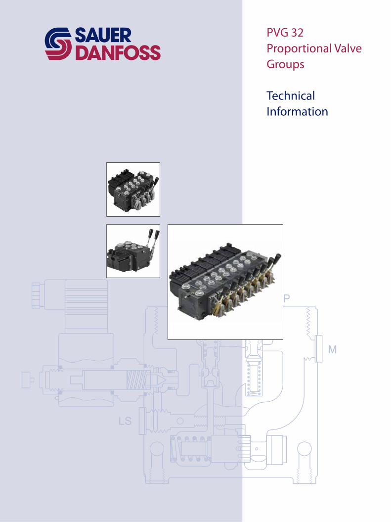
PVG 32Proportional Valve Groups
Technical Information
2 520L0344 • Rev HA • Nov 2011
PVG 32 Proportional Valve GroupTechnical Information
Table of revisionsDate Page Changed RevJun 2010 69 Code numbers changed GDDec 2010 80 New back cover GENov 2011 All Major update HA
Revision History
Literature Reference
© 2011 Sauer-Danfoss. All rights reserved.
Sauer-Danfoss accepts no responsibility for possible errors in catalogs, brochures and other printed material. Sauer -Danfoss reserves the right to alter its products without prior notice. This also applies to products already ordered provided that such alterations can be made without affecting agreed specifications. All trademarks in this material are properties of their respective owners. Sauer-Danfoss, the Sauer-Danfoss logotype, the Sauer-Danfoss S-icon, PLUS+1™, What really matters is inside® and Know-How in Motion™ are trademarks of the Sauer-Danfoss Group. Frontpage: F301302, F301306, F301056, Drawing 157-195.
Literature reference for PVG productsTitle Type Order numberPVG 32 Metric ports Technical Information 11051935PVG 100 Technical Information 520L0720PVG 120 Technical Information 520L0356PVBZ Technical Information 520L0721PVSK Technical Information 520L0556PVED-CC Technical Information 520L0665PVED-CX Series 4 Technical Information 11070179PVE Series 4 Technical Information 520L0553
3520L0344 • Rev HA • Nov 2011
PVG 32 Proportional Valve GroupTechnical InformationContents
General Information
Safety in Application
General Information
Function
General ............................................................................................................................................................... 7Accessories ....................................................................................................................................................... 8
Rated Pressure .....................................................................................................................................8Remote control units ............................................................................................................................... 8Actuation modules ................................................................................................................................... 8
Building in Safety ........................................................................................................................................... 9FMEA (Failure Mode and Effect Analysis) IEC EN 61508 .............................................................. 9Hazard and Risk Analysis ISO 12100-1 / 14121............................................................................... 9
Control System Example ............................................................................................................................10PVG32 – Mainly used in system with fixed displacement pumps .........................................12PVG100 – Alternative LS dump or pilot supply disconnect .....................................................12PVG120 – Pump disconnect/block for variable pumps ............................................................12
Load Sensing Open Circuit System ........................................................................................................13Pictorial circuit diagram ..................................................................................................................13
Pressure Compensated Controls ............................................................................................................14Pressure compensated system characteristics .............................................................................14Typical applications for pressure compensated systems .........................................................14
Typical operating curve ...................................................................................................................14Simple closed-center circuit ...........................................................................................................14
Remote Pressure Compensated Controls ............................................................................................15Remote pressure compensated system characteristics ............................................................15Typical applications for remote pressure compensated systems .........................................15
Typical operating curve ...................................................................................................................15Closed center circuit with remote PC ...........................................................................................15
Load Sensing Controls ................................................................................................................................16Typical operating curve ...................................................................................................................16Load sensing circuit ..........................................................................................................................16
Load sensing system characteristics ................................................................................................17
PVG 32 with Open Centre PVP • PVB with Flow Control Spool ...................................................18PVG 32 with Closed Centre PVP • PVB with Flow Control Spool ..................................................18PVG 32 Sectional View ................................................................................................................................19
PVG 32 Sectional Drawing ..............................................................................................................19PVPC Plug for External Pilot Oil Supply ................................................................................................20
PVPC with check valve for open centre PVP .................................................................................20Hydraulic diagram ............................................................................................................................20
PVPC without check valve for open or closed centre PVP .......................................................21Hydraulic diagram ............................................................................................................................21
PVMR, Friction Detent .................................................................................................................................22PVMR ....................................................................................................................................................22
PVMF, Mechanical Float Position Lock ..................................................................................................22PVMF ....................................................................................................................................................22
PVBS, Main Spools for Flow Control (Standard) ................................................................................23PVBS, Main Spools for Flow Control (with Linear Characteristic) ................................................23PVBS, Main Spools for Pressure Control ...............................................................................................23PVPX, Electrical LS Unloading Valve ......................................................................................................24
Fast Unloader - Minimize System Pressure Peaks........................................................................24
4 520L0344 • Rev HA • Nov 2011
PVG 32 Proportional Valve GroupTechnical InformationContents
PVG 32 Valve Group .....................................................................................................................................25Technical data for PVG 32 and PVPX ............................................................................................25
PVH, Hydraulic Actuation ..........................................................................................................................26PVM, Mechanical Actuation ......................................................................................................................26
Technical data for PVH ....................................................................................................................26Technical data for PVM ....................................................................................................................26
PVE Technical Data .......................................................................................................................................27Technical data for PVEO and PVEM ..............................................................................................27Reaction time PVEO and PVEM .....................................................................................................27Technical data for PVEA, PVEH and PVES ....................................................................................28Reaction time .....................................................................................................................................28Oil consumption PVEO and PVEM ................................................................................................29Oil consumption PVEA, PVEH and PVES ......................................................................................29Ambient temperature ......................................................................................................................29
PVPX, Electrical LS Unloading Valve ......................................................................................................30Technical data for PVPX...................................................................................................................30
PVEA/PVEH/PVES, ........................................................................................................................................31Connection to Fault Monitoring Output ..............................................................................................31
Function ...........................................................................................................................................................32Hydraulic Actuation .....................................................................................................................................32Features ...........................................................................................................................................................32Input-Output Relation ................................................................................................................................33Connections ...................................................................................................................................................33
Temperature range ...........................................................................................................................33Oil viscosity .........................................................................................................................................33Pilot pressure (over tank)* ..............................................................................................................33Input control ......................................................................................................................................33Filtering in the hydraulic system ...................................................................................................33Deutsch Version ................................................................................................................................33AMP Version .......................................................................................................................................33Enclosure .............................................................................................................................................33
PVP, Pump Side Moduls ...................................................................................................................35PVP, Pump side moduls ....................................................................................................................36PVB, Basic Modules – Without Adjustable LSA/B Pressure Limiting Valves ..........................37PVB, Basic Modules - Without Adjustable LSa/b Pressure Limiting Valves ...........................38PVB, Basic Modules - With Adjustable LSa/b Pressure Limiting Valves ..................................39PVM, Mechanical Actuation ...........................................................................................................40PVMD, Cover for Mechanical Actuation ......................................................................................40PVH, Hydraulic Actuation ...............................................................................................................40PVMR, Friction Detent ......................................................................................................................40PVMF, Mechanical Float Position ..................................................................................................40PVLA, Suction Valve (fitted in PVB)................................................................................................41PVLP, Shock and Suction Valve (Fitted in PVB) ..........................................................................41PVS, End Plate ....................................................................................................................................42PVAS, Assembly Kit ...........................................................................................................................42PVPX, Electrical LS Unloaded Valve ..............................................................................................43PVPC, Plug for External Pilot Oil Supply .......................................................................................43
Technical Data
PVHC Electrical Actuation
Modules and Code Numbers
5520L0344 • Rev HA • Nov 2011
PVG 32 Proportional Valve GroupTechnical Information
Technical Characteristics
Dimensions
Hydraulic Systems
Other Operating Conditions
General .............................................................................................................................................................44PVP, Pump Side Module .............................................................................................................................44
Pressure relief valve characteristic ................................................................................................44Neutral flow pressure characteristic (open centre) ...................................................................44
PVB, High Flow Modules ............................................................................................................................45High oil flow characteristic .............................................................................................................45
PVB, Basic Modules ......................................................................................................................................46Linear characteristic .........................................................................................................................46
PVB without pressure compensation, open centre PVP ...........................................................47Characteristic for fully displaced flow control spools. .............................................................47
PVB without pressure compensation, closed centre PVP ........................................................48Characteristic for pressure drop PVB at max. main spool travel ..........................................49Characteristic for pressure drop PVB for open spool in neutral position .............................49Load-independent oil flow characteristic, pressure-compensated PVB ..............................50Oil flow characteristic at LS pressure limiting, pressure-compensated PVB .......................50
PVLP, Shock and Suction Valve ...............................................................................................................51PVLA,Suction Valve ......................................................................................................................................51
PVLP, shock valve characteristic ....................................................................................................51PVLA, suction valve characteristic ................................................................................................51
Pressure Control Spools Characteristics in Extreme Positions .....................................................52Examples of How To Use the Characteristics for Pressure Control Spools ...............................54
Example of determining the oil flow ...............................................................................................54Example of determining spool size ..................................................................................................54
Characteristics for Float Position Main Spools ...................................................................................55Characteristic of oil flow, spool travel and voltage ..................................................................55Pressure drop A/B → T at max. spool travel within the proportional range .....................56Pressure drop A/B → T in float position .......................................................................................56
Dimensions .....................................................................................................................................................57Control Lever Positions ..............................................................................................................................59
Base with an angle of 22.5° ............................................................................................................59Base with an angle of 37.5° ............................................................................................................59
Manually Actuated PVG 32 – Fixed Displacement Pump ..............................................................60Electrically Actuated PVG 32 – Variable Displacement Pump ......................................................61
Oil .......................................................................................................................................................................62Particle Content, Degree of Contamination .......................................................................................62
Mineral oil ..................................................................................................................................................62Non-flammable fluids............................................................................................................................62Biodegradable oils ..................................................................................................................................62
Filtration...........................................................................................................................................................63System filters ............................................................................................................................................63Internal filters ...........................................................................................................................................63
Contents
6 520L0344 • Rev HA • Nov 2011
PVG 32 Proportional Valve GroupTechnical Information
Standard PC Spools ...............................................................................................................................64Standard PC Spools, Hydraulic Actuation ...........................................................................................66
Standard FC Spools ................................................................................................................................67Standard FC Spools ......................................................................................................................................68Standard FC Spools, Hydraulic Actuation ............................................................................................69PVMR, FC Spools for Friction Detent .....................................................................................................69FC Spools for Mechanical Float Position PVMF..................................................................................70FC Spools with Linear Flow Characteristic .........................................................................................71
PVB, basic valves ...............................................................................................................................72PVPC, plugs .........................................................................................................................................72PVM, mechanical actuation ...........................................................................................................72PVAS, assembly kit ............................................................................................................................72PVP, pump side module ...................................................................................................................73PVLP, shock/and anti-cavitation valves .......................................................................................73End plate, PVS, PVSI ..........................................................................................................................73
Standard and option assembly ..........................................................................................................75Reordering .................................................................................................................................................75Pressure setting limits ...........................................................................................................................76
Max. pressure setting of LSA and LSB valves relative to PVLP shock valve .........................76Order Specification Forms .........................................................................................................................77
Module Selection Chart
Order Specification
Contents
7520L0344 • Rev HA • Nov 2011
PVG 32 Proportional Valve GroupTechnical Information
Valve systemPVG 32 is a hydraulic load sensing valve designed to give maximum flexibility. From a simple load sensing directional valve, to an advanced electrically controlled load-independent proportional valve.
The PVG 32 module system makes it possible to build up a valve group to meet requirements precisely.The compact external dimensions of the valve remain unchanged whatever combination is specified.
General features PVG 32• Load-independent flow control:
– Oil flow to an individual function is independent of the load pressure of this function– Oil flow to one function is independent of the load pressure of other functions
• Good regulation characteristics• Energy-saving• Up to 10 basic modules per valve group• Several types of connection threads• Low weight
PVP – pump side module• Built-in pressure relief valve• System pressure up to 350 bar [5075 psi]• Pressure gauge connection• Versions:
– Open centre version for systems with fixed displacement pumps– Closed centre version for systems with variable displacement pumps– Pilot oil supply for electrical actuator built into the pump side module– Versions prepared for electrical LS unloading valve PVPX
PVB, basic module• Interchangeable spools• Depending on requirements the basic module can be supplied with:
– Integrated pressure compensator in channel P– Check valve in channel P– Shock/suction valves– LS pressure limiting valves individually adjustable for ports A and B– Different spool variants
General
General
8 520L0344 • Rev HA • Nov 2011
PVG 32 Proportional Valve GroupTechnical Information
General
Remote control units• Electrical remote control units
– PVRE, PVRET– PVREL– PVRES– Prof 1– Prof 1 CIP
• Hydraulic remote control unit– PVRHH
Accessories
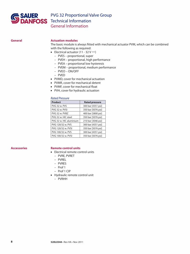
Actuation modulesThe basic module is always fitted with mechanical actuator PVM, which can be combined with the following as required:• Electrical actuator (11 - 32 V ---__)
– PVES – proportional, super– PVEH – proportional, high performance– PVEA – proportional low hysteresis– PVEM – proportional, medium performance– PVEO – ON/OFF– PVED
• PVMD, cover for mechanical actuation• PVMR, cover for mechanical detent• PVMF, cover for mechanical float• PVH, cover for hydraulic actuation
Rated PressureProduct Rated pressurePVG 32 w. PVS 300 bar [4351 psi]PVG 32 w. PVSI 350 bar [5076 psi]PVG 32 w. PVBZ 400 bar [5800 psi]PVG 32 w. HIC steel 350 bar [5076 psi]PVG 32 w. HIC aluminium 210 bar [3046 psi]PVG 120/32 w. PVS 300 bar [4351 psi]PVG 120/32 w. PVSI 350 bar [5076 psi]PVG 100/32 w. PVS 300 bar [4351 psi]PVG 100/32 w. PVSI 350 bar [5076 psi]
General Information
9520L0344 • Rev HA • Nov 2011
PVG 32 Proportional Valve GroupTechnical InformationSafety in Application
Building in Safety All makes and all types of control valves (incl. proportional valves) can fail. Thus the necessary protection against the serious consequences of function failure should always be built into the system. For each application an assessment should be made for the consequences of pressure failure and uncontrolled or blocked movements.
To determine the degree of protection that is required to be built into the application, system tools such an FMEA (Failure Mode and Effect Analysis) and Hazard and Risk Analysis can be used.
FMEA (Failure Mode and Effect Analysis) IEC EN 61508FMEA is a tool used for analyzing potential risks. This analytical technique is utilized to define, identify, and prioritize the elimination or reduction of known and/or potential failures from a given system before it is released for production.Please refer to IEC FMEA Standard 61508.
Hazard and Risk Analysis ISO 12100-1 / 14121This analysis is a tool used in new applications as it will indicate whether there are special safety considerations to be meet according to the machine directives EN 13849. Dependent on the determined levels conformety this analysis will detirmine if any extra requirements for the product design, development process, production process or maintenance, i.e. the complete product life cycle.
WWarningAll makes/brands and types of directional control valves – inclusive proportional valves – can fail and cause serious damage. It is therefore important to analyze all aspects of the application. Because the proportional valves are used in many different operation conditions and applications, the manufacturer of the application is alone responsible for making the final selection of the products – and assuring that all performance, safety and warning requirements of the application are met. The process of choosing the control system – and safety levels – is governed by the machine directives EN 13849 (Safety related requirements for control systems).
10 520L0344 • Rev HA • Nov 2011
PVG 32 Proportional Valve GroupTechnical Information
SupplyControl
NeutralDetection
Signal Conditioning
FailureDetection
FaultMonitoring
PVE fault output
SignalConditioning
SupplyMain controller
Hydraulic deactivation
HMI / Joystick
ControlSignal
Emergency stop andMan present switch Motion detection sensor
PVE
Main control valve
Main power supply(battery)
Joystick neutral switch
P301 317
Control System Example
Safety in Application
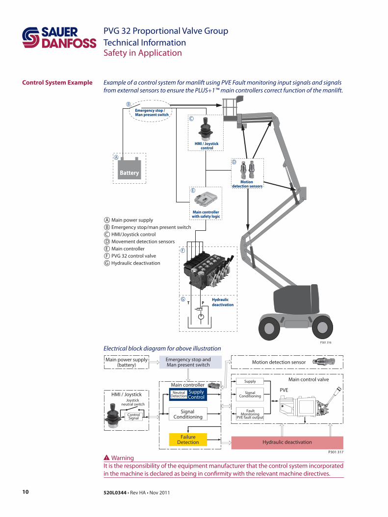
Example of a control system for manlift using PVE Fault monitoring input signals and signals from external sensors to ensure the PLUS+1™ main controllers correct function of the manlift.
Electrical block diagram for above illustration
Emergency stop / Man present switch
T P
BatteryMotion
detection sensors
Main controller with safety logic
Hydraulic deactivation
HMI / Joystick control
A
B
C
D
E
F
G
P301 316
A Main power supplyB Emergency stop/man present switchC HMI/Joystick controlD Movement detection sensorsE Main controllerF PVG 32 control valveG Hydraulic deactivation
WWarningIt is the responsibility of the equipment manufacturer that the control system incorporated in the machine is declared as being in confirmity with the relevant machine directives.
11520L0344 • Rev HA • Nov 2011
PVG 32 Proportional Valve GroupTechnical Information
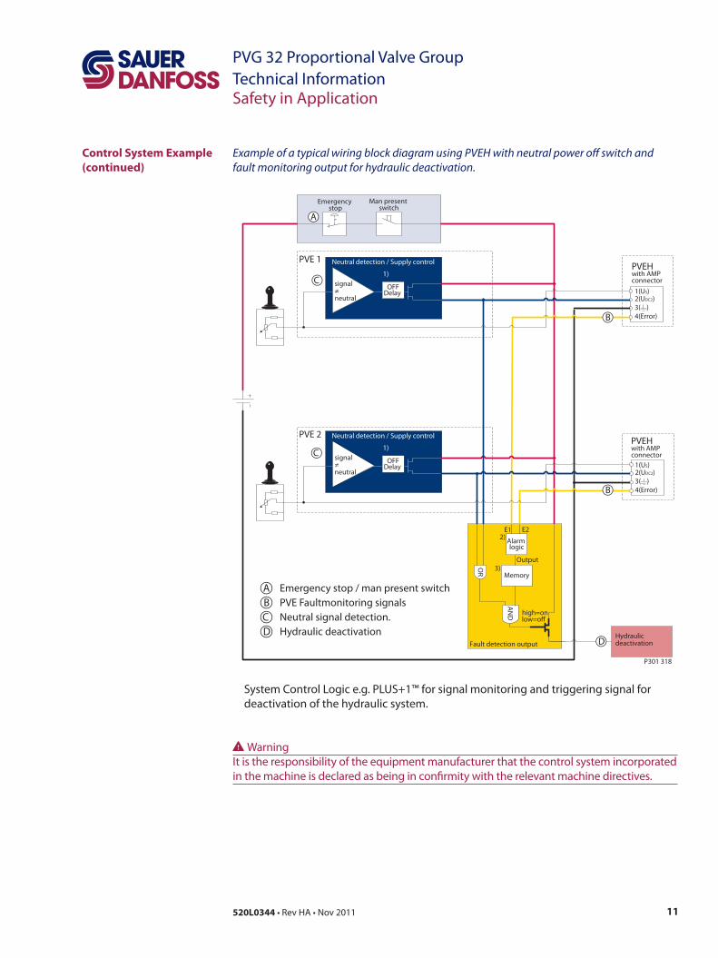
Example of a typical wiring block diagram using PVEH with neutral power off switch and fault monitoring output for hydraulic deactivation.
System Control Logic e.g. PLUS+1™ for signal monitoring and triggering signal for deactivation of the hydraulic system.
Fault detection output
high=onlow=o
Alarm logic
2)
Memory3)
E1 E2
Output
AN
D
OR
Neutral detection / Supply control
signal≠neutral
OFFDelay
1)
2(UDC2)3( )4(Error)
1(US)
PVEH with AMP connector
2(UDC2)3( )4(Error)
1(US)
PVEHwith AMP connector
Hydraulicdeactivation
Neutral detection / Supply control
signal≠neutral
OFFDelay
1)
PVE 1
PVE 2
Emergency stop
Man present switch
C
C
D
B
B
A
P301 318
Safety in Application
A Emergency stop / man present switchB PVE Faultmonitoring signalsC Neutral signal detection.D Hydraulic deactivation
Control System Example (continued)
WWarningIt is the responsibility of the equipment manufacturer that the control system incorporated in the machine is declared as being in confirmity with the relevant machine directives.
12 520L0344 • Rev HA • Nov 2011
PVG 32 Proportional Valve GroupTechnical Information
Neutral detection / Supply control
signal≠neutral
OFFDelay
1)
Fault detection output
2(UDC2)3( )4(Error)
1(US)
2(DI-B)3( )
1(DI-A)
PVEH-DI AMP connector
4(UDC)
PVEH-DIAMP supply connector
2(UDC2)3( )4(Error)
1(US)
2(DI-B)3( )
1(DI-A)
PVEH-DI AMP connector
4(UDC)
PVEH-DIAMP supply connector
AN
D
Hydraulicdeactivation
high=onlow=o
Neutral detection / Supply control
signal≠neutral
OFFDelay
1)
PVE 1
PVE 2
Fault detection
DelayDILogic Memory
US
DI-ADI-B
2)4)3)
Output
Fault detection
DelayDILogic Memory
US
DI-ADI-B
2)4)3)
Output
OR
Emergency Stop
Man present switch
P301 319
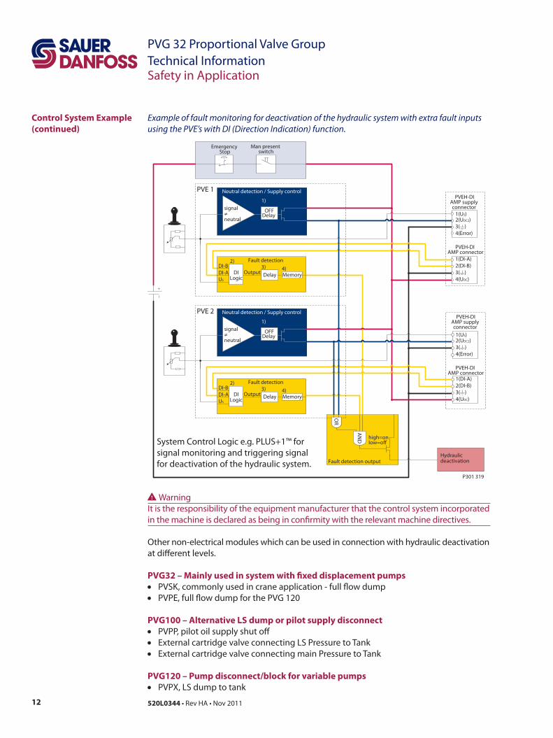
Example of fault monitoring for deactivation of the hydraulic system with extra fault inputs using the PVE’s with DI (Direction Indication) function.
System Control Logic e.g. PLUS+1™ for signal monitoring and triggering signal for deactivation of the hydraulic system.
Control System Example (continued)
Safety in Application
Other non-electrical modules which can be used in connection with hydraulic deactivation at different levels.
PVG32 – Mainly used in system with fixed displacement pumps• PVSK, commonly used in crane application - full flow dump• PVPE, full flow dump for the PVG 120
PVG100 – Alternative LS dump or pilot supply disconnect• PVPP, pilot oil supply shut off• External cartridge valve connecting LS Pressure to Tank• External cartridge valve connecting main Pressure to Tank
PVG120 – Pump disconnect/block for variable pumps• PVPX, LS dump to tank
WWarningIt is the responsibility of the equipment manufacturer that the control system incorporated in the machine is declared as being in confirmity with the relevant machine directives.
13520L0344 • Rev HA • Nov 2011
PVG 32 Proportional Valve GroupTechnical Information
Load Sensing Open Circuit System
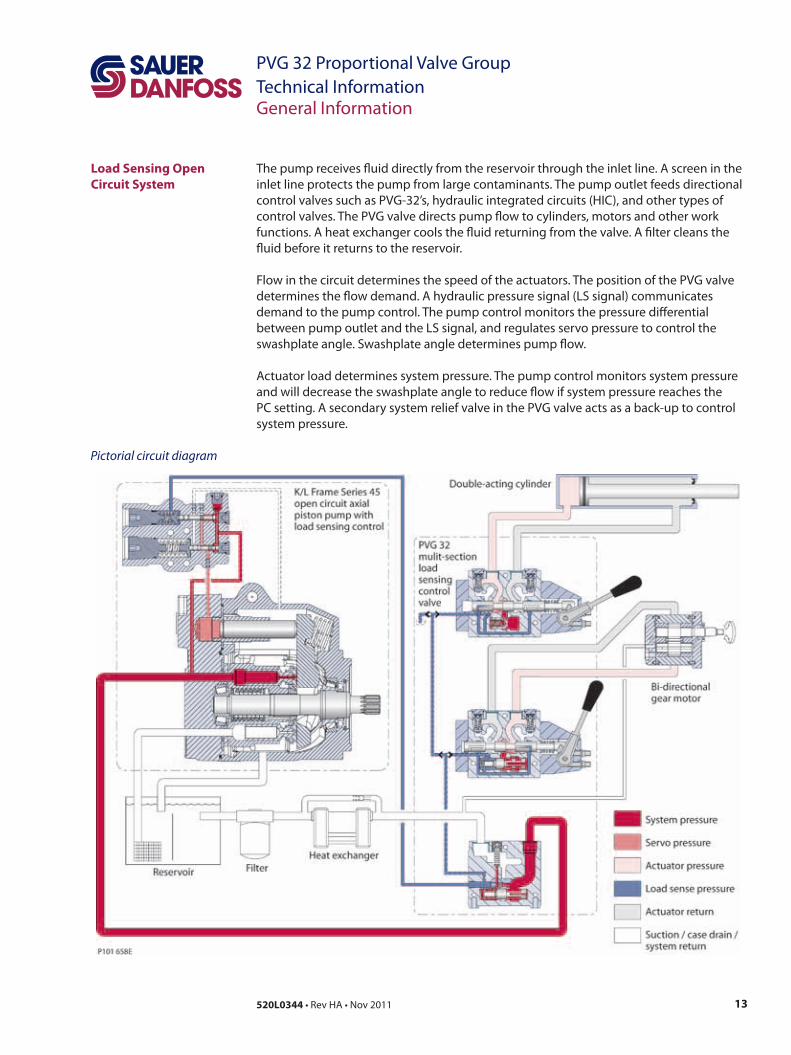
The pump receives fluid directly from the reservoir through the inlet line. A screen in the inlet line protects the pump from large contaminants. The pump outlet feeds directional control valves such as PVG-32’s, hydraulic integrated circuits (HIC), and other types of control valves. The PVG valve directs pump flow to cylinders, motors and other work functions. A heat exchanger cools the fluid returning from the valve. A filter cleans the fluid before it returns to the reservoir.
Flow in the circuit determines the speed of the actuators. The position of the PVG valve determines the flow demand. A hydraulic pressure signal (LS signal) communicates demand to the pump control. The pump control monitors the pressure differential between pump outlet and the LS signal, and regulates servo pressure to control the swashplate angle. Swashplate angle determines pump flow.
Actuator load determines system pressure. The pump control monitors system pressure and will decrease the swashplate angle to reduce flow if system pressure reaches the PC setting. A secondary system relief valve in the PVG valve acts as a back-up to control system pressure.
General Information
Pictorial circuit diagram
14 520L0344 • Rev HA • Nov 2011
PVG 32 Proportional Valve GroupTechnical Information
Pressure Compensated Controls
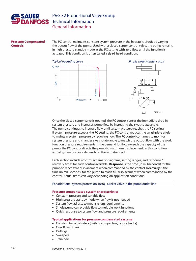
The PC control maintains constant system pressure in the hydraulic circuit by varying the output flow of the pump. Used with a closed center control valve, the pump remains in high pressure standby mode at the PC setting with zero flow until the function is actuated. This condition is often called a dead head condition.
P101 965
Simple closed-center circuit
00
Q max
Pressure
Flow
P101 166E
PC s
ettin
g
Typical operating curve
Once the closed center valve is opened, the PC control senses the immediate drop in system pressure and increases pump flow by increasing the swashplate angle. The pump continues to increase flow until system pressure reaches the PC setting. If system pressure exceeds the PC setting, the PC control reduces the swashplate angle to maintain system pressure by reducing flow. The PC control continues to monitor system pressure and changes swashplate angle to match the output flow with the work function pressure requirements. If the demand for flow exceeds the capacity of the pump, the PC control directs the pump to maximum displacement. In this condition, actual system pressure depends on the actuator load.
Each section includes control schematic diagrams, setting ranges, and response / recovery times for each control available. Response is the time (in milliseconds) for the pump to reach zero displacement when commanded by the control. Recovery is the time (in milliseconds) for the pump to reach full displacement when commanded by the control. Actual times can vary depending on application conditions.
For additional system protection, install a relief valve in the pump outlet line
Pressure compensated system characteristics• Constant pressure and variable flow• High pressure standby mode when flow is not needed• System flow adjusts to meet system requirements• Single pump can provide flow to multiple work functions• Quick response to system flow and pressure requirements
Typical applications for pressure compensated systems• Constant force cylinders (bailers, compactors, refuse trucks)• On/off fan drives• Drill rigs• Sweepers• Trenchers
General Information
15520L0344 • Rev HA • Nov 2011
PVG 32 Proportional Valve GroupTechnical Information
Remote Pressure Compensated Controls
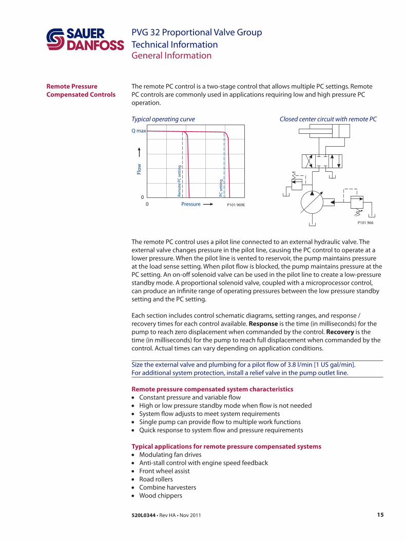
The remote PC control is a two-stage control that allows multiple PC settings. Remote PC controls are commonly used in applications requiring low and high pressure PC operation.
P101 966
Closed center circuit with remote PC
The remote PC control uses a pilot line connected to an external hydraulic valve. The external valve changes pressure in the pilot line, causing the PC control to operate at a lower pressure. When the pilot line is vented to reservoir, the pump maintains pressure at the load sense setting. When pilot flow is blocked, the pump maintains pressure at the PC setting. An on-off solenoid valve can be used in the pilot line to create a low-pressure standby mode. A proportional solenoid valve, coupled with a microprocessor control, can produce an infinite range of operating pressures between the low pressure standby setting and the PC setting.
Each section includes control schematic diagrams, setting ranges, and response / recovery times for each control available. Response is the time (in milliseconds) for the pump to reach zero displacement when commanded by the control. Recovery is the time (in milliseconds) for the pump to reach full displacement when commanded by the control. Actual times can vary depending on application conditions.
Size the external valve and plumbing for a pilot flow of 3.8 l/min [1 US gal/min]. For additional system protection, install a relief valve in the pump outlet line.
Remote pressure compensated system characteristics• Constant pressure and variable flow• High or low pressure standby mode when flow is not needed• System flow adjusts to meet system requirements• Single pump can provide flow to multiple work functions• Quick response to system flow and pressure requirements
Typical applications for remote pressure compensated systems• Modulating fan drives• Anti-stall control with engine speed feedback• Front wheel assist• Road rollers• Combine harvesters• Wood chippers
00
Q max
Pressure
Flo
w
P101 969E
PC s
etti
ng
Rem
ote
PC
set
tin
g
Typical operating curve
General Information
16 520L0344 • Rev HA • Nov 2011
PVG 32 Proportional Valve GroupTechnical Information
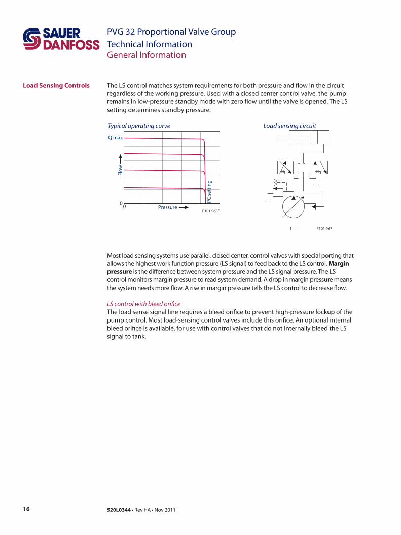
Load Sensing Controls The LS control matches system requirements for both pressure and flow in the circuit regardless of the working pressure. Used with a closed center control valve, the pump remains in low-pressure standby mode with zero flow until the valve is opened. The LS setting determines standby pressure.
P101 967
Load sensing circuit
Most load sensing systems use parallel, closed center, control valves with special porting that allows the highest work function pressure (LS signal) to feed back to the LS control. Margin pressure is the difference between system pressure and the LS signal pressure. The LS control monitors margin pressure to read system demand. A drop in margin pressure means the system needs more flow. A rise in margin pressure tells the LS control to decrease flow.
LS control with bleed orificeThe load sense signal line requires a bleed orifice to prevent high-pressure lockup of the pump control. Most load-sensing control valves include this orifice. An optional internal bleed orifice is available, for use with control valves that do not internally bleed the LS signal to tank.
00
P101 968EPC
set
tin
g
Flo
w
Pressure
Q max
Typical operating curve
General Information
17520L0344 • Rev HA • Nov 2011
PVG 32 Proportional Valve GroupTechnical Information
Load Sensing Controls (continued)
General Information
Integral PC functionThe LS control also performs as a PC control, decreasing pump flow when system pressure reaches the PC setting. The pressure compensating function has priority over the load sensing function.
Each section includes control schematic diagrams, setting ranges, and response / recovery times for each control available. Response is the time (in milliseconds) for the pump to reach zero displacement when commanded by the control. Recovery is the time (in milliseconds) for the pump to reach full displacement when commanded by the control. Actual times can vary depending on application conditions.
For additional system protection, install a relief valve in the pump outlet line.
Load sensing system characteristics• Variable pressure and flow• Low pressure standby mode when flow is not needed• System flow adjusted to meet system requirements• Lower torque requirements during engine start-up• Single pump can supply flow and regulate pressure for multiple circuits• Quick response to system flow and pressure requirements
18 520L0344 • Rev HA • Nov 2011
PVG 32 Proportional Valve GroupTechnical Information
PVG 32 with Open Centre PVP • PVB with Flow Control Spool
PVG 32 with Closed Centre PVP • PVB with Flow Control Spool
Function
When the pump is started and the main spools in the individual basic modules (11) are in the neutral position, oil flows from the pump, through connection P, across the pressure adjustment spool (6) to tank. The oil flow led across the pressure adjustment spool determines the pump pressure (stand-by pressure).
When one or more of the main spools are actuated, the highest load pressure is fed through the shuttle valve circuit (10) to the spring chamber behind the pressure adjustment spool (6), and completely or partially closes the connection to tank.Pump pressure is applied to the right-hand side of the pressure adjustment spool (6). The pressure relief valve (1) will open should the load pressure exceed the set value, diverting pump flow back to tank.
In a pressure-compensated basic module the compensator (14) maintains a constant pressure drop across the main spool – both when the load changes and when a module with a higher load pressure is actuated. With a non pressure-compensated basic module incorporating a load drop check valve (18) in channel P, the check valve prevents return oil flow.The basic module can be supplied without the load drop check valve in channel P for functions with over-centre valves.
The shock valves PVLP (13) with fixed setting and the suction valves PVLA (17) on ports A and B are used for the protection of the individual working function against overload and/or cavitation.
An adjustable LS pressure limiting valve (12) can be built into the A and B ports of pressure-compensated basic modules to limit the pressure from the individual working functions.
The LS pressure limiting valves save energy compared with the shock valves PVLP:• with PVLP all the oil flow to the working function will be led across the combined
shock and suction valves to tank if the pressure exceeds the fixed setting.• with LS pressure limiting valves an oil flow of about 2 l/min [0.5 US gal/min] will be led
across the LS pressure limiting valve to tank if the pressure exceeds the valve setting.
In the closed centre version an orifice (5) and a plug (7) have been fitted instead of the plug (4). This means that the pressure adjustment spool (6) will only open to tank when the pressure in channel P exceeds the set value of the pressure relief valve (1).
In load sensing systems the load pressure is led to the pump regulator via the LS connection (8).
In the neutral position the pump control sets the displacement so that leakage in the system is compensated for, to maintain the set stand-by pressure.When a main spool is actuated the pump regulator will adjust the displacement so that the set differential pressure between P and LS is maintained.
The pressure relief valve (1) in PVP should be set at a pressure of approx. 30 bar [435 psi] above maximum system pressure (set on the pump or external pressure relief valve).
19520L0344 • Rev HA • Nov 2011
PVG 32 Proportional Valve GroupTechnical InformationFunction
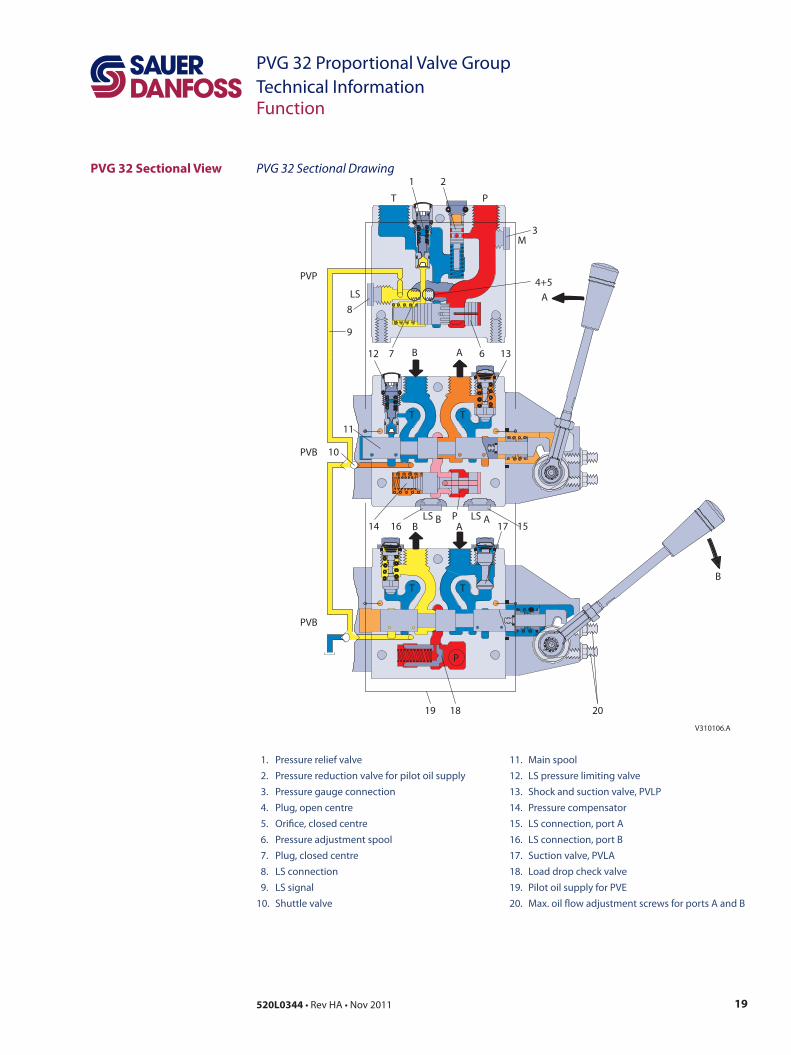
PVG 32 Sectional View PVG 32 Sectional Drawing
1. Pressure relief valve 2. Pressure reduction valve for pilot oil supply 3. Pressure gauge connection 4. Plug, open centre 5. Orifice, closed centre 6. Pressure adjustment spool 7. Plug, closed centre 8. LS connection 9. LS signal 10. Shuttle valve
11. Main spool 12. LS pressure limiting valve 13. Shock and suction valve, PVLP 14. Pressure compensator 15. LS connection, port A 16. LS connection, port B 17. Suction valve, PVLA 18. Load drop check valve 19. Pilot oil supply for PVE 20. Max. oil flow adjustment screws for ports A and B
1 2
3
4+5
67
9
8
T P
M
ALS
B A12 13
11
10
14 16 17 15
T T
LS B LS AB A
P
T TB
19
P
18 20
V310106.A
PVP
PVB
PVB
20 520L0344 • Rev HA • Nov 2011
PVG 32 Proportional Valve GroupTechnical InformationFunction
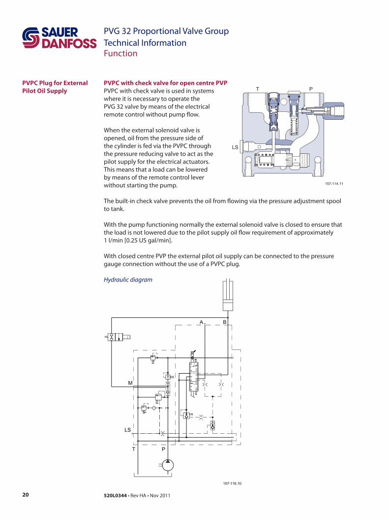
PVPC Plug for External Pilot Oil Supply
PVPC with check valve for open centre PVP
The built-in check valve prevents the oil from flowing via the pressure adjustment spool to tank.
With the pump functioning normally the external solenoid valve is closed to ensure that the load is not lowered due to the pilot supply oil flow requirement of approximately 1 l/min [0.25 US gal/min].
With closed centre PVP the external pilot oil supply can be connected to the pressure gauge connection without the use of a PVPC plug.
Hydraulic diagram
PVPC with check valve is used in systems where it is necessary to operate the PVG 32 valve by means of the electrical remote control without pump flow.
When the external solenoid valve is opened, oil from the pressure side of the cylinder is fed via the PVPC through the pressure reducing valve to act as the pilot supply for the electrical actuators. This means that a load can be lowered by means of the remote control lever without starting the pump.
21520L0344 • Rev HA • Nov 2011
PVG 32 Proportional Valve GroupTechnical InformationFunction
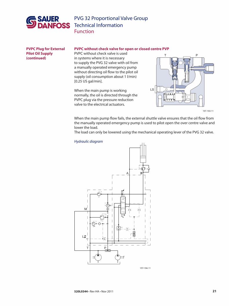
PVPC Plug for External Pilot Oil Supply (continued)
PVPC without check valve for open or closed centre PVPPVPC without check valve is used in systems where it is necessary to supply the PVG 32 valve with oil from a manually operated emergency pump without directing oil flow to the pilot oil supply (oil consumption about 1 l/min)[0.25 US gal/min].
When the main pump is working normally, the oil is directed through the PVPC plug via the pressure reduction valve to the electrical actuators.
When the main pump flow fails, the external shuttle valve ensures that the oil flow from the manually operated emergency pump is used to pilot open the over centre valve and lower the load. The load can only be lowered using the mechanical operating lever of the PVG 32 valve.
Hydraulic diagram
22 520L0344 • Rev HA • Nov 2011
PVG 32 Proportional Valve GroupTechnical Information
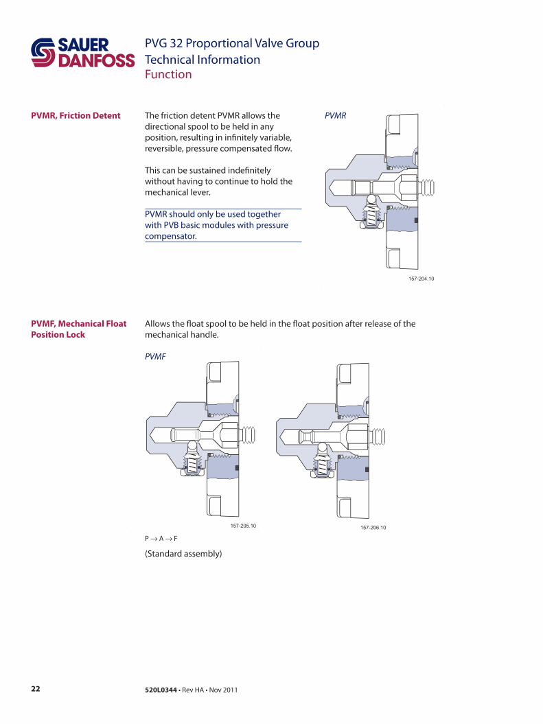
The friction detent PVMR allows the directional spool to be held in any position, resulting in infinitely variable, reversible, pressure compensated flow.
This can be sustained indefinitely without having to continue to hold the mechanical lever.
PVMR should only be used together with PVB basic modules with pressure compensator.
PVMR
Function
PVMR, Friction Detent
PVMF, Mechanical Float Position Lock
P → A → F
(Standard assembly)
Allows the float spool to be held in the float position after release of the mechanical handle.
PVMF
23520L0344 • Rev HA • Nov 2011
PVG 32 Proportional Valve GroupTechnical InformationFunction
PVBS, Main Spools for Flow Control (Standard)
PVBS, Main Spools for Flow Control (with Linear Characteristic)
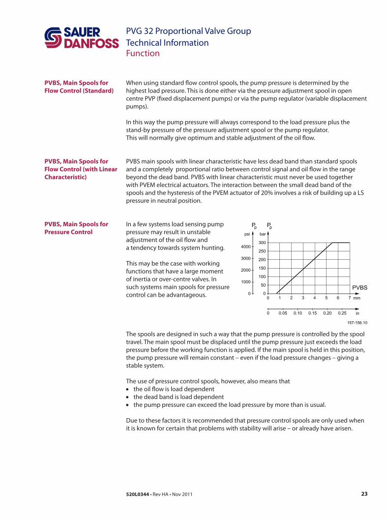
PVBS, Main Spools for Pressure Control
When using standard flow control spools, the pump pressure is determined by the highest load pressure. This is done either via the pressure adjustment spool in open centre PVP (fixed displacement pumps) or via the pump regulator (variable displacement pumps).
In this way the pump pressure will always correspond to the load pressure plus the stand-by pressure of the pressure adjustment spool or the pump regulator.This will normally give optimum and stable adjustment of the oil flow.
PVBS main spools with linear characteristic have less dead band than standard spools and a completely proportional ratio between control signal and oil flow in the range beyond the dead band. PVBS with linear characteristic must never be used together with PVEM electrical actuators. The interaction between the small dead band of the spools and the hysteresis of the PVEM actuator of 20% involves a risk of building up a LS pressure in neutral position.
In a few systems load sensing pump pressure may result in unstable adjustment of the oil flow and a tendency towards system hunting.
This may be the case with working functions that have a large moment of inertia or over-centre valves. In such systems main spools for pressure control can be advantageous.
The spools are designed in such a way that the pump pressure is controlled by the spool travel. The main spool must be displaced until the pump pressure just exceeds the load pressure before the working function is applied. If the main spool is held in this position, the pump pressure will remain constant – even if the load pressure changes – giving a stable system.
The use of pressure control spools, however, also means that• the oil flow is load dependent• the dead band is load dependent• the pump pressure can exceed the load pressure by more than is usual.
Due to these factors it is recommended that pressure control spools are only used when it is known for certain that problems with stability will arise – or already have arisen.
24 520L0344 • Rev HA • Nov 2011
PVG 32 Proportional Valve GroupTechnical Information
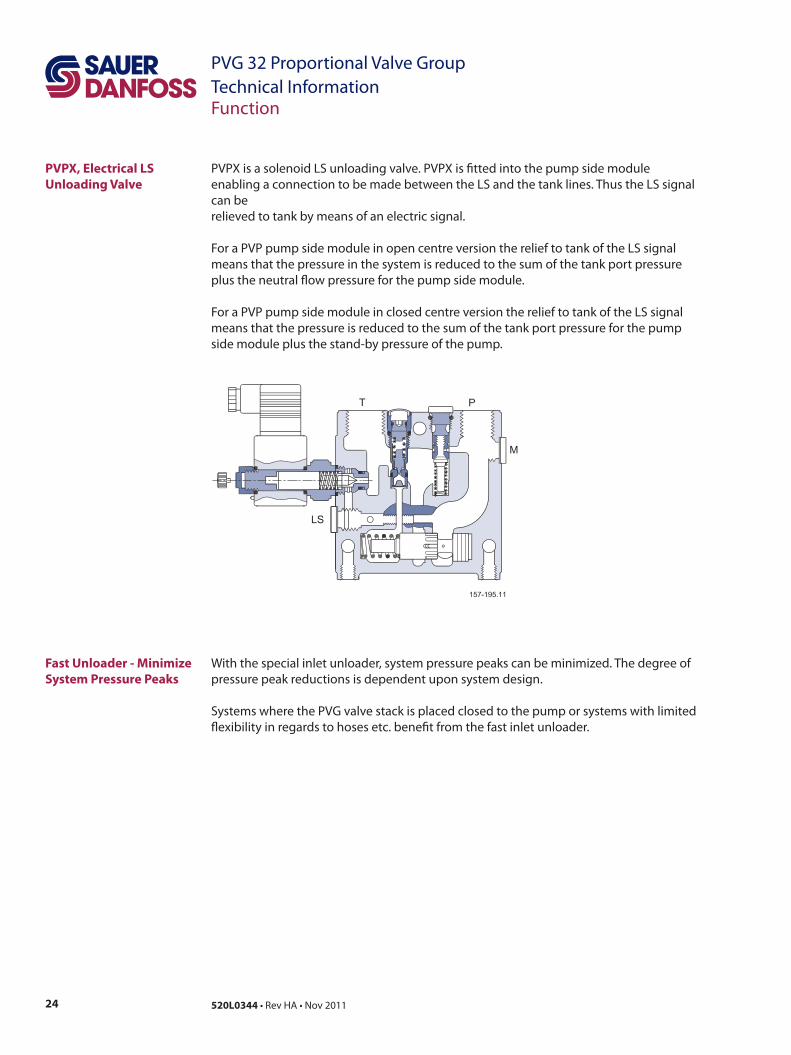
PVPX is a solenoid LS unloading valve. PVPX is fitted into the pump side module enabling a connection to be made between the LS and the tank lines. Thus the LS signal can be relieved to tank by means of an electric signal.
For a PVP pump side module in open centre version the relief to tank of the LS signal means that the pressure in the system is reduced to the sum of the tank port pressure plus the neutral flow pressure for the pump side module.
For a PVP pump side module in closed centre version the relief to tank of the LS signalmeans that the pressure is reduced to the sum of the tank port pressure for the pump side module plus the stand-by pressure of the pump.
Function
PVPX, Electrical LS Unloading Valve
Fast Unloader - Minimize System Pressure Peaks
With the special inlet unloader, system pressure peaks can be minimized. The degree of pressure peak reductions is dependent upon system design.
Systems where the PVG valve stack is placed closed to the pump or systems with limited flexibility in regards to hoses etc. benefit from the fast inlet unloader.
25520L0344 • Rev HA • Nov 2011
PVG 32 Proportional Valve GroupTechnical InformationTechnical Data
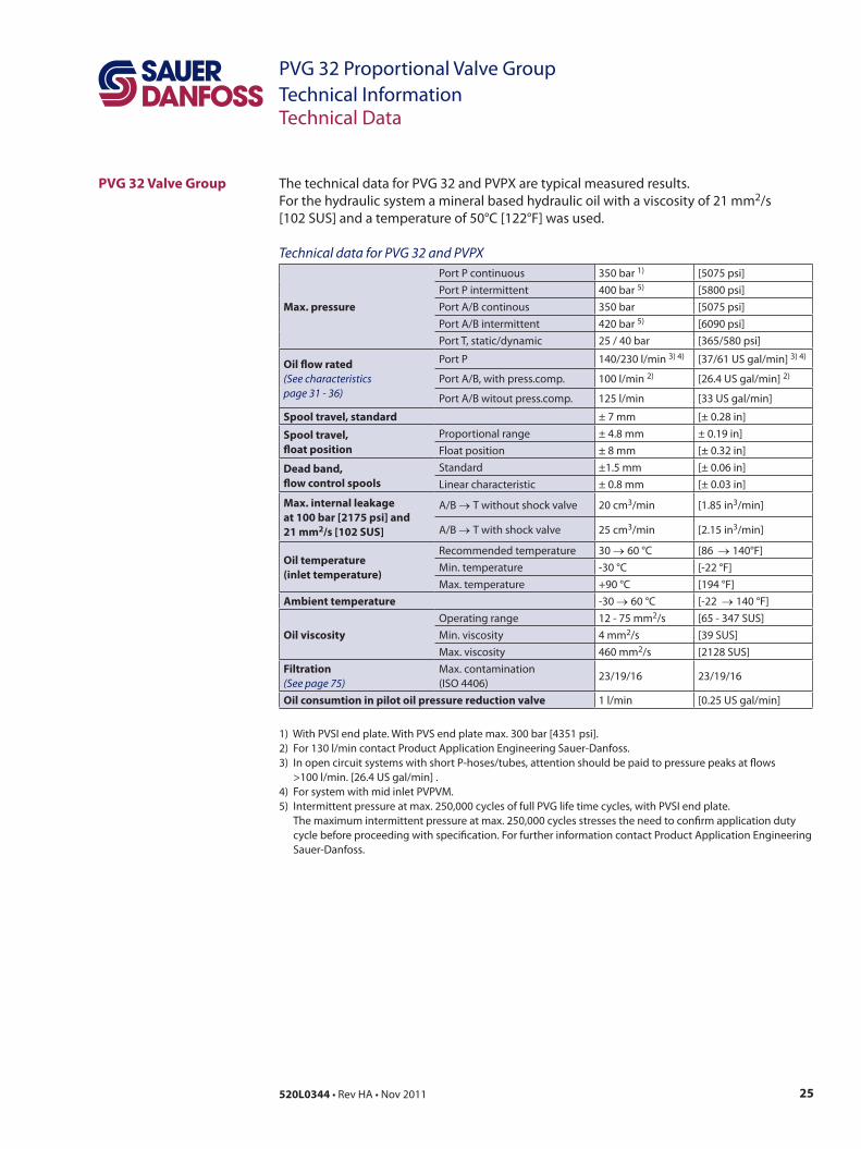
PVG 32 Valve Group The technical data for PVG 32 and PVPX are typical measured results. For the hydraulic system a mineral based hydraulic oil with a viscosity of 21 mm2/s [102 SUS] and a temperature of 50°C [122°F] was used.
Technical data for PVG 32 and PVPX
Max. pressure
Port P continuous 350 bar 1) [5075 psi]Port P intermittent 400 bar 5) [5800 psi]Port A/B continous 350 bar [5075 psi]Port A/B intermittent 420 bar 5) [6090 psi]Port T, static/dynamic 25 / 40 bar [365/580 psi]
Oil flow rated(See characteristicspage 31 - 36)
Port P 140/230 l/min 3) 4) [37/61 US gal/min] 3) 4)
Port A/B, with press.comp. 100 l/min 2) [26.4 US gal/min] 2)
Port A/B witout press.comp. 125 l/min [33 US gal/min]
Spool travel, standard ± 7 mm [± 0.28 in]
Spool travel, float position
Proportional range ± 4.8 mm ± 0.19 in]Float position ± 8 mm [± 0.32 in]
Dead band,flow control spools
Standard ±1.5 mm [± 0.06 in]Linear characteristic ± 0.8 mm [± 0.03 in]
Max. internal leakageat 100 bar [2175 psi] and21 mm2/s [102 SUS]
A/B →T without shock valve 20 cm3/min [1.85 in3/min]
A/B →T with shock valve 25 cm3/min [2.15 in3/min]
Oil temperature(inlet temperature)
Recommended temperature 30 →60 °C [86 →140°F]Min. temperature -30 °C [-22 °F]Max. temperature +90 °C [194 °F]
Ambient temperature -30 →60 °C [-22 →140 °F]
Oil viscosityOperating range 12 - 75 mm2/s [65 - 347 SUS]Min. viscosity 4 mm2/s [39 SUS]Max. viscosity 460 mm2/s [2128 SUS]
Filtration(See page 75)
Max. contamination(ISO 4406)
23/19/16 23/19/16
Oil consumtion in pilot oil pressure reduction valve 1 l/min [0.25 US gal/min]
1) With PVSI end plate. With PVS end plate max. 300 bar [4351 psi]. 2) For 130 l/min contact Product Application Engineering Sauer-Danfoss. 3) In open circuit systems with short P-hoses/tubes, attention should be paid to pressure peaks at flows
>100 l/min. [26.4 US gal/min] . 4) For system with mid inlet PVPVM.5) Intermittent pressure at max. 250,000 cycles of full PVG life time cycles, with PVSI end plate.
The maximum intermittent pressure at max. 250,000 cycles stresses the need to confirm application duty cycle before proceeding with specification. For further information contact Product Application Engineering Sauer-Danfoss.
26 520L0344 • Rev HA • Nov 2011
PVG 32 Proportional Valve GroupTechnical InformationTechnical Data
PVM, Mechanical Actuation
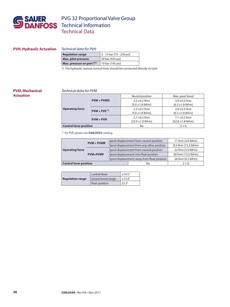
Technical data for PVM
Operating force
PVM + PVMDNeutral position Max. spool travel
2.2 ±0.2 N•m[5.0 ±1.8 lbf•in]
2.8 ±0.2 N•m[6.3 ±1.8 lbf•in]
PVM + PVE 1) 2.2 ±0.2 N•m[5.0 ±1.8 lbf•in]
2.8 ±0.2 N•m [6.3 ±1.8 lbf•in]
PVM + PVH2.7 ±0.2 N•m
[23.9 ±1.8 lbf•in]7.1 ±0.2 N•m
[62.8 ±1.8 lbf•in]Control lever position No 2 × 6
1) for PVE please see 520L0553 catalog.
Operating force
PVM + PVMRSpool displacement from neutral position 17 N•m [3.8 lbf•in]Spool displacement from any other position 8.5 N•m [73.3 lbf•in]
PVM+PVMFSpool displacement from neutral position 22 N•m [5.0 lbf•in]Spool displacement into float position 60 N•m [13.5 lbf•in]Spool displacement away from float position 28 N•m [6.3 lbf•in]
Control lever position No 2 × 6
Technical data for PVHRegulation range 5 - 15 bar [75 - 220 psi]Max. pilot pressure 30 bar [435 psi]Max. pressure on port T1) 10 bar [145 psi]
1) The hydraulic remote control lever should be connected directly to tank.
Regulation rangecontrol lever ±19.5°proportional range ±13.4°float position 22.3°
PVH, Hydraulic Actuation

27520L0344 • Rev HA • Nov 2011
PVG 32 Proportional Valve GroupTechnical InformationTechnical Data
PVE Technical Data The following technical data are from typical test results. For the hydraulic system a mineral based hydraulic oil with a viscosity of 21 mm2/s [102 SUS] and a temperature of 50 °C [122 °F] were used. Technical data for PVEO and PVEM
PVEO and PVEM
Supply voltage UDC
rated 12 V DC 24 V DCrange 11 V to 15 V 22 V to 30 Vmax. ripple 5%
Current consumption at rated voltage 0.65 A @ 12 V 0.33 A @ 24 V
Signal voltage (PVEM)neutral 0.5 x UDC
A-port ↔B-port 0.25 • UDC to 0.75 • UDC
Signal current at rated voltage (PVEM) 0.25 mA 0.50 mAInput impedance in relation to 0.5 • UDC 12 KΩPower consumption 8 W
Reaction time PVEO and PVEM
Supply voltage FunctionPVEO
ON/OFFs
PVEO-RON/OFF
s
PVEM Prop. medium
s
Disconnected by means of neutral switch
Reaction time from neutralposition to max. spool travel
max. 0.235 0.410 0.700
rated 0.180 0.350 0.450
min. 0.120 0.250 0.230
Disconnected by meansof neutral switch
Reaction time from max. spool travel to neutral position
max. 0.175 0.330 0.175
rated 0.090 0.270 0.090
min. 0.065 0.250 0.065
Constant voltageReaction time from neutral position to max. spool position
max. - - 0.700rated - - 0.450min. - - 0.230
Constant voltageReaction time from max. spool travel to neutral position
max. - - 0.700rated - - 0.450min. - - 0.230
Hysteresis1) rated - - 20%
1) Hysteresis is indicated at rated voltage and f = 0.02 Hz for one cycle (one cycle = neutral ->full A -> full B -> neutral.
28 520L0344 • Rev HA • Nov 2011
PVG 32 Proportional Valve GroupTechnical InformationTechnical Data
PVE Technical Data (continued)
Spoo
l pos
ition
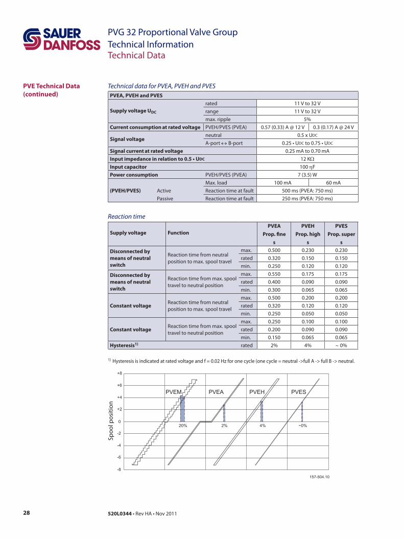
Technical data for PVEA, PVEH and PVESPVEA, PVEH and PVES
Supply voltage UDC
rated 11 V to 32 V range 11 V to 32 Vmax. ripple 5%
Current consumption at rated voltage PVEH/PVES (PVEA) 0.57 (0.33) A @ 12 V 0.3 (0.17) A @ 24 V
Signal voltageneutral 0.5 x UDC
A-port ↔B-port 0.25 • UDC to 0.75 • UDC
Signal current at rated voltage 0.25 mA to 0.70 mAInput impedance in relation to 0.5 • UDC 12 KΩInput capacitor 100 ηFPower consumption PVEH/PVES (PVEA) 7 (3.5) W
(PVEH/PVES)Max. load 100 mA 60 mA
Active Reaction time at fault 500 ms (PVEA: 750 ms)Passive Reaction time at fault 250 ms (PVEA: 750 ms)
Reaction time
Supply voltage FunctionPVEA
Prop. fines
PVEHProp. high
s
PVESProp. super
s
Disconnected by means of neutral switch
Reaction time from neutralposition to max. spool travel
max. 0.500 0.230 0.230rated 0.320 0.150 0.150min. 0.250 0.120 0.120
Disconnected by means of neutral switch
Reaction time from max. spool travel to neutral position
max. 0.550 0.175 0.175rated 0.400 0.090 0.090min. 0.300 0.065 0.065
Constant voltageReaction time from neutral position to max. spool travel
max. 0.500 0.200 0.200rated 0.320 0.120 0.120min. 0.250 0.050 0.050
Constant voltageReaction time from max. spool travel to neutral position
max. 0.250 0.100 0.100rated 0.200 0.090 0.090min. 0.150 0.065 0.065
Hysteresis1) rated 2% 4% ∼0%
1) Hysteresis is indicated at rated voltage and f = 0.02 Hz for one cycle (one cycle = neutral ->full A -> full B -> neutral.

29520L0344 • Rev HA • Nov 2011
PVG 32 Proportional Valve GroupTechnical Information
Technical Data(continued)
Oil viscosity
Oil viscosity
range12 - 75 mm2/s [65 - 347 SUS]
min. 4 mm2/s [39 SUS]max. 460 mm2/s [2128 SUS]
Note: Max. start up viscosity 2500 mm2/s
Filtering in the hydraulic system Max. allowed degree of contamination
23/19/16(ISO 4406, 1999 version)
Oil temperature
Oil temperature
Rec. range30 - 60˚C
[86 -140˚F]min. -30˚C [-22˚F]max. 90˚C [194˚F]
Ambient temperatureAmbient temperature range Rec.
-30° →+60°C [-22° → +140°F]
Oil consumption PVEO and PVEM
Supply voltage FunctionPVEO
ON/OFFPVEM
Prop. medium
Without voltagePilot oil flow per PVE
neutral0 l/min
[0 US gal/min]0 l/min
[0 US gal/min]
With voltagePilot oil flow per PVE
locked0.1 l/min
[0.026 US gal/min]0.1 l/min
[0.026 US gal/min]
one actuation(neutral →max.)
0.002 l[0.053 US gal]
0.002 l[0.053 US gal]
continuous actuations(neutral → max.)
0.7 l/min[0.185 US gal/min]
0.5 l/min[0.132 US gal/min]
Oil consumption PVEA, PVEH and PVESSupply voltage
FunctionPVEA
Prop. finePVEH
Prop. highPVES
Prop. superWithout voltage
Pilot oil flow per PVE - neutral0 l/min
[0 US gal/min]0 l/min
[0 US gal/min]0.3 l/min
[0.106 US gal/min]
With voltage
Pilot oil flow per PVE
locked0.4 l/min
[0.132 US gal/min]0.1 l/min
[0.026 US gal/min]0.1 l/min
[0.053 US gal/min]one actuation(neutral →max.)
0.002 l[0.053 US gal]
0.002 l[0.053 US gal]
0.002 l[0.053 US gal]
continuous actuations
1.0 l/min[0.200 US gal/min]
0.7 l/min[0.290 US gal/min]
0.8 l/min[0.290 US gal/min]
Technical Data
30 520L0344 • Rev HA • Nov 2011
PVG 32 Proportional Valve GroupTechnical Information
PVPX, Electrical LS Unloading Valve
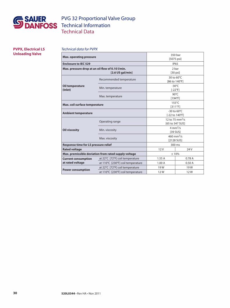
Technical Data
Technical data for PVPX
Max. operating pressure 350 bar
[5075 psi]
Enclosure to IEC 529 IP65
Max. pressure drop at an oil flow of 0.10 l/min. [2.6 US gal/min]
2 bar [30 psi]
Oil temperature (Inlet)
Recommended temperature30 to 60°C
[86 to 140°F]
Min. temperature-30°C
[-22°F]
Max. temperature90°C
[194°F]
Max. coil surface temperature155°C
[311°F]
Ambient temperature-30 to 60°C
[-22 to 140°F]
Oil viscosity
Operating range12 to 75 mm2/s [65 to 347 SUS]
Min. viscosity4 mm2/s[39 SUS]
Max. viscosity460 mm2/s[2128 SUS]
Response time for LS pressure relief 300 msRated voltage 12 V 24 VMax. premissible deviation from rated supply voltage ± 10%
Current consumption at rated voltage
at 22°C [72°F] coil temperature 1.55 A 0.78 Aat 110°C [230°F] coil temperature 1.00 A 0.50 A
Power consumptionat 22°C [72°F] coil temperature 19 W 19 Wat 110°C [230°F] coil temperature 12 W 12 W
31520L0344 • Rev HA • Nov 2011
PVG 32 Proportional Valve GroupTechnical Information
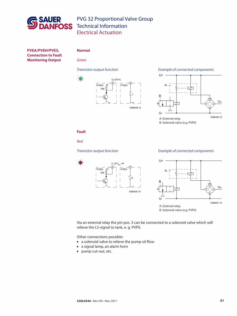
Normal
Green
Transistor output function Example of connected components
PVEA/PVEH/PVES, Connection to Fault Monitoring Output
A: External relayB: Solenoid valve (e.g. PVPX)
A: External relayB: Solenoid valve (e.g. PVPX)
Fault
Red
Transistor output function Example of connected components
Via an external relay the pin pos. 3 can be connected to a solenoid valve which will relieve the LS-signal to tank, e. g. PVPX.
Other connections possible:• a solenoid valve to relieve the pump oil flow• a signal lamp, an alarm horn• pump cut-out, etc.
Electrical Actuation
32 520L0344 • Rev HA • Nov 2011
PVG 32 Proportional Valve GroupTechnical Information
Function
Hydraulic Actuation
Features
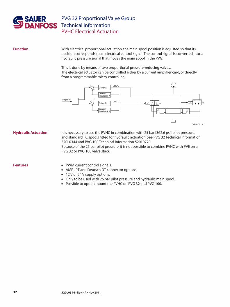
With electrical proportional actuation, the main spool position is adjusted so that its position corresponds to an electrical control signal. The control signal is converted into a hydraulic pressure signal that moves the main spool in the PVG.
This is done by means of two proportional pressure-reducing valves. The electrical actuator can be controlled either by a current amplifier card, or directly from a programmable micro-controller.
It is necessary to use the PVHC in combination with 25 bar [362.6 psi] pilot pressure, and standard FC spools fitted for hydraulic actuation. See PVG 32 Technical Information 520L0344 and PVG 100 Technical Information 520L0720.Because of the 25 bar pilot pressure, it is not possible to combine PVHC with PVE on a PVG 32 or PVG 100 valve stack.
• PWM current control signals.• AMP JPT and Deutsch DT connector options. • 12 V or 24 V supply options. • Only to be used with 25 bar pilot pressure and hydraulic main spool.• Possible to option mount the PVHC on PVG 32 and PVG 100.
V310 002.A
+-
Setpoint
Driver A
CurrentFeedback A
Driver B
CurrentFeedback B
+-
-
-
PVHC Electrical Actuation
33520L0344 • Rev HA • Nov 2011
PVG 32 Proportional Valve GroupTechnical InformationPVHC Electrical Actuation
Temperature range
Ambient-30 °C to 80 °C
[-22 °F to 176 °F]
Medium-20 °C to 80 °C [-4 °F to 176 °F]
Oil viscosityRange 12 - 75 mm2/s [65 - 350 SUS]
Minimum 4 mm2/s [40 SUS]
Maximum 400 mm2/s [2130 SUS]
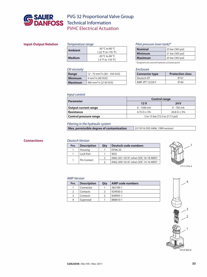
Input-Output Relation
EnclosureConnector type Protection classDeutsch DT IP 67AMP JPT 12/24 V IP 66
Pilot pressure (over tank)*Nominal 25 bar [363 psi]
Minimum 21 bar [305 psi]
Maximum 25 bar [363 psi]
* Designed to be used with hydraulic activated spools.
Input control
ParameterControl range
12 V 24 V
Output current range 0 - 1500 mA 0 - 750 mA
Resistance 4.75 Ω ± 5% 20.8 Ω ± 5%
Control pressure range 5 to 15 bar [72.5 to 217.5 psi]
Filtering in the hydraulic system Max. permissible degree of contamination 23/19/16 (ISO 4406, 1999 version)
Deutsch VersionPos. Description Qty Deutsch code numbers
1 Housing 1 DT06-2S1 Lock Part 1 W2S
1 Pin Contact2 0462-201-16141 when SOC 16-18 AWG*2 0462-209-16141 when SOC 14-16 AWG*
AMP VersionPos. Description Qty AMP code numbers
1 Connector 1 282189-12 Contacts 2 929930-33 Contacts 2 828905-14 Superseal 1 880810-1
Connections
V310 003.A
4
3
2
1
V310 004.A
1
34 520L0344 • Rev HA • Nov 2011
PVG 32 Proportional Valve GroupTechnical Information
V310 001.A
E
D
C
B
AAA
E
D
C
B
AAA
A/B
US gal/min
mm
in
l/min
PVM
PVM
7 6 5 4 3 2 1 0 1 2 3 4 5 6 7
100
90
80
70
60
50
40
30
20
10
0
25
20
15
10
5
a
a
1.5 1.5
0.28 0.24 0.20 0.16 0.12 0.08 0.04 0 0.04 0.08 0.12 0.16 0.20 0.24 0.28
AP P B
Q
1
1
1
8
8
8
8
1
1
1
8
8
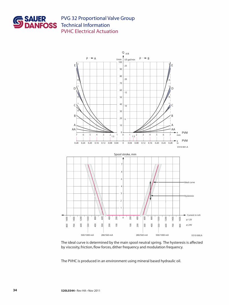
The ideal curve is determined by the main spool neutral spring. The hysteresis is affected by viscosity, friction, flow forces, dither frequency and modulation frequency.
The PVHC is produced in an environment using mineral based hydraulic oil.
0
400
200
600
1
2
120080
0
1000
1400
Current in mA
3
4
5
6
Spool stroke, mm
7
160040
0
200
600
1200 80
0
1000
1400
1600
200
100
300
600
400
500
700
800
200
100
300
600
400
500
700
800
@ 12V
@ 24V
V310 000.A
Ideal curve
Hysteresis
280/560 mA 500/1000 mA280/560 mA500/1000 mA
PVHC Electrical Actuation

35520L0344 • Rev HA • Nov 2011
PVG 32 Proportional Valve GroupTechnical Information
PVP, Pump Side ModulsSymbol Description Code number
Open centre pump side module forpumps with fixed displacement.
For purely machanically actuatedvalve groups
P = G ½T = G ¾
157B5000
P = 78–14T = 1116–12
157B5200
P, T = G ¾ 157B5100
P, T = 1116–12 157B5300
Closed centre pump side module for pumps with vaiable displacement.
P = G ½T = G ¾
157B5001
P = 78–14T = 1116–12
157B5201
For purely mechanically actuatedvalve groups
P, T = G ¾ 157B5101
P, T = 1116–12 157B5301
Open centre pump side module for pumps with fixed displacement.
With pilot oil supply for electrically actuated valves
P = G ½T = G ¾
157B5010
P = 78–14T = 1116–12 157B5210
P, T = G ¾ 157B5110
P, T = 1116–12 157B5310
Closed centre pump side modulepumps with variable displacement.
With pilot oil supply for electrically actuated valves
P = G ½T = G ¾
157B5011
P = 78–14T = 1116–12 157B5211
P, T = G ¾ 157B5111
P, T = 1116–12 157B5311
Open centre pump side module forpumps with fixed displacement.
With pilot oil supply for electricallyactuated valves
Connection for electricalLS unloading valve, PVPX
P = G ½T = G ¾
157B5012
P = 78–14T =
1116–12
157B5212
P, T = G ¾ 157B5112
P, T = 1116–12 157B5312
Closed centre pump side modulepumps with variable displacement
With pilot oil supply
Connection for electricalLS unloading valve, PVPX
P = G ½T = G ¾
157B5013
P = 78–14T = 1116–12
157B5213
P, T = G ¾ 157B5113
P, T = 1116–12 157B5313
Modules and Code Numbers
Connections:P = G ½ in; 14 mm deep or G ¾ in; 16 mm deep / LS, M = G ¼ in; 12 mm deep / T = G ¾ in; 16 mm deep.P = 78–14; 0.65 in deep or 1116–12; 0.75 in deep / LS, M = ½–20; 0.47 in deep / T = 1116–12; 0.75 in deep.
36 520L0344 • Rev HA • Nov 2011
PVG 32 Proportional Valve GroupTechnical InformationModules and Code Numbers
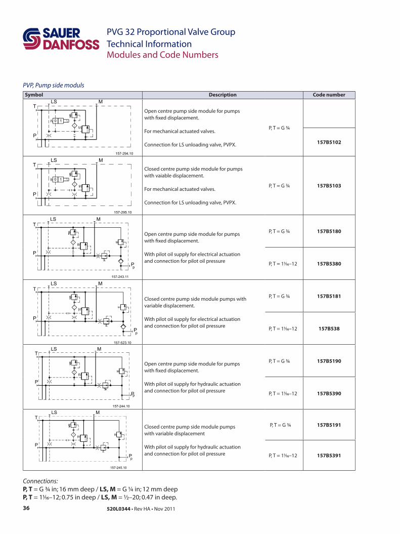
PVP, Pump side modulsSymbol Description Code number
Open centre pump side module for pumps with fixed displacement.
For mechanical actuated valves.
Connection for LS unloading valve, PVPX.
P, T = G ¾
157B5102
Closed centre pump side module for pumps with vaiable displacement.
For mechanical actuated valves.
Connection for LS unloading valve, PVPX.
P, T = G ¾ 157B5103
Open centre pump side module for pumps with fixed displacement.
With pilot oil supply for electrical actuation and connection for pilot oil pressure
P, T = G ¾ 157B5180
P, T = 1116–12 157B5380
Closed centre pump side module pumps with variable displacement.
With pilot oil supply for electrical actuation and connection for pilot oil pressure
P, T = G ¾ 157B5181
P, T = 1116–12 157B538
Open centre pump side module for pumps with fixed displacement.
With pilot oil supply for hydraulic actuation and connection for pilot oil pressure
P, T = G ¾ 157B5190
P, T = 1116–12 157B5390
Closed centre pump side module pumps with variable displacement
With pilot oil supply for hydraulic actuation and connection for pilot oil pressure
P, T = G ¾ 157B5191
P, T = 1116–12 157B5391
Connections:P, T = G ¾ in; 16 mm deep / LS, M = G ¼ in; 12 mm deep P, T = 1116–12; 0.75 in deep / LS, M = ½–20; 0.47 in deep.
37520L0344 • Rev HA • Nov 2011
PVG 32 Proportional Valve GroupTechnical InformationModules and Code Numbers
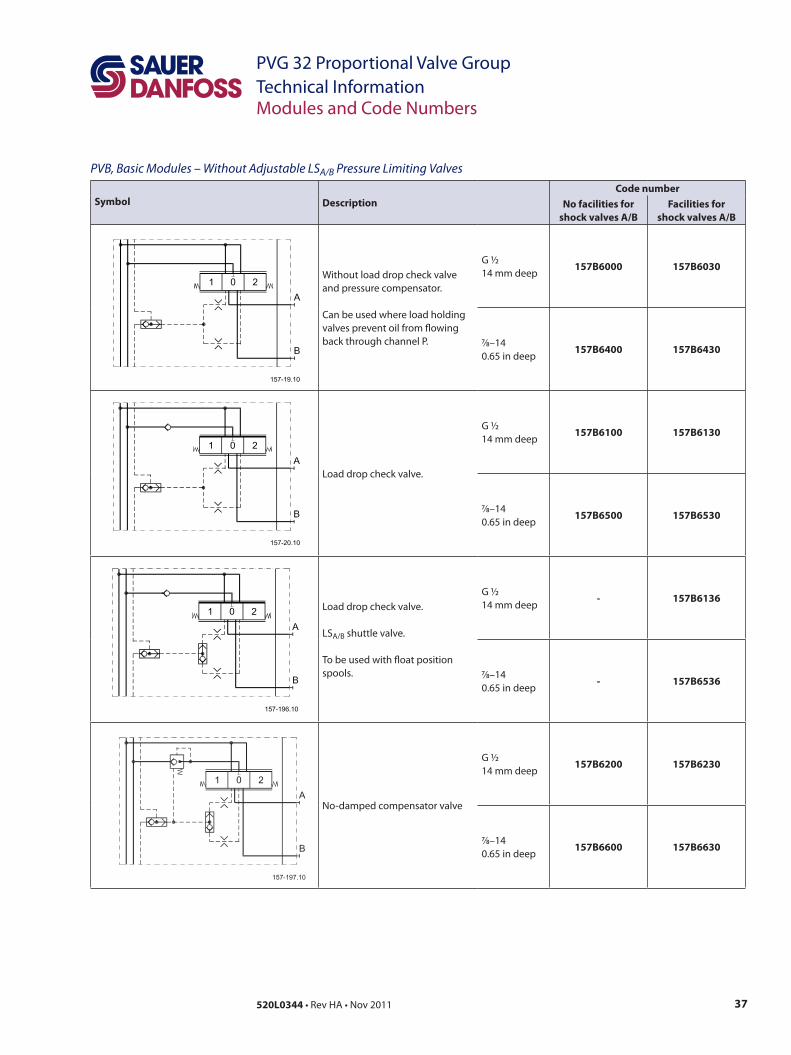
PVB, Basic Modules – Without Adjustable LSA/B Pressure Limiting Valves
Symbol DescriptionCode number
No facilities for shock valves A/B
Facilities for shock valves A/B
Without load drop check valve and pressure compensator.
Can be used where load holding valves prevent oil from flowing back through channel P.
G ½14 mm deep
157B6000 157B6030
78–140.65 in deep
157B6400 157B6430
Load drop check valve.
G ½14 mm deep
157B6100 157B6130
78–140.65 in deep
157B6500 157B6530
Load drop check valve.
LSA/B shuttle valve.
To be used with float position spools.
G ½14 mm deep
- 157B6136
78–140.65 in deep
- 157B6536
No-damped compensator valve
G ½14 mm deep
157B6200 157B6230
78–140.65 in deep
157B6600 157B6630
38 520L0344 • Rev HA • Nov 2011
PVG 32 Proportional Valve GroupTechnical Information
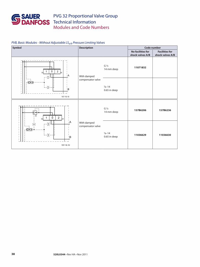
PVB, Basic Modules - Without Adjustable LSa/b Pressure Limiting ValvesSymbol Description Code number
No facilities forshock valves A/B
Facilities for shock valves A/B
With dampedcompensator valve
G ½14 mm deep
11071832
78–140.65 in deep
Modules and Code Numbers
With dampedcompensator valve
G ½14 mm deep
157B6206 157B6236
78–140.65 in deep
11036629 11036630

39520L0344 • Rev HA • Nov 2011
PVG 32 Proportional Valve GroupTechnical Information
PVB, Basic Modules - With Adjustable LSa/b Pressure Limiting Valves
Symbol DescriptionCode number
No facilities for shock valves A/B
Facilities for shock valves A/B
With non-damped compensator valve.
Adjustable LSA/B pressure limiting valves;
External LS connection port A/B. Also used for float position spools.
G ½14 mm deep
157B6203 157B6233
78–140.65 in deep
157B6603 157B6633
Damped compensator valve.
Adjustable LSA/B pressure limiting valves
External LS connection port A/B.
G ½14 mm deep
157B6208 157B6238
78–140.65 in deep
- 11036631
Modules and Code Numbers
40 520L0344 • Rev HA • Nov 2011
PVG 32 Proportional Valve GroupTechnical Information
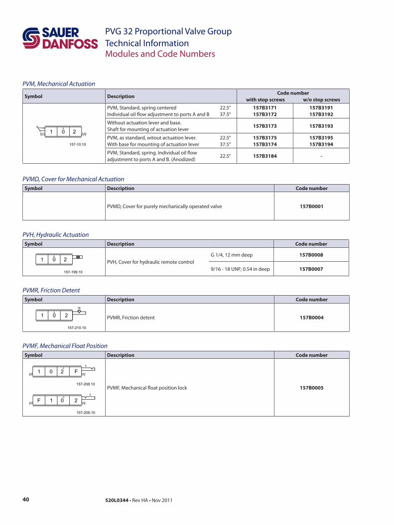
PVM, Mechanical Actuation
Symbol DescriptionCode number
with stop screws w/o stop screwsPVM, Standard, spring centered Individual oil flow adjustment to ports A and B
22.5°37.5°
157B3171157B3172
157B3191157B3192
Without actuation lever and base.Shaft for mounting of actuation lever
157B3173 157B3193
PVM, as standard, witout actuation lever. With base for mounting of actuation lever
22.5°37.5°
157B3175157B3174
157B3195157B3194
PVM, Standard, spring. Individual oil flowadjustment to ports A and B. (Anodized)
22.5° 157B3184 -
PVMD, Cover for Mechanical ActuationSymbol Description Code number
PVMD, Cover for purely mechanically operated valve 157B0001
PVH, Hydraulic ActuationSymbol Description Code number
PVH, Cover for hydraulic remote controlG 1/4, 12 mm deep 157B0008
9/16 - 18 UNF; 0.54 in deep 157B0007
PVMR, Friction DetentSymbol Description Code number
PVMR, Friction detent 157B0004
PVMF, Mechanical Float PositionSymbol Description Code number
PVMF, Mechanical float position lock 157B0005
Modules and Code Numbers

41520L0344 • Rev HA • Nov 2011
PVG 32 Proportional Valve GroupTechnical Information
PVLA, Suction Valve (fitted in PVB)Symbol Description Code number
Suction valve forport A and/orB.
157B2001
Plug for connecting the nonactive port to tank, when using a single acting spool.
157B2002
PVLP, Shock and Suction Valve (Fitted in PVB)
Symbol DescriptionSetting
bar [psi]Code number
Shock and suction valvefor port A and/or B.(Not adjustable)
32 460 157B203250 725 157B205063 914 157B206380 1160 157B2080
100 1450 157B2100125 1813 157B2125140 2031 157B2140150 2175 157B2150160 2320 157B2160175 2538 157B2175190 2755 157B2190210 3045 157B2210230 3335 157B2230240 3480 157B2240250 3625 157B2250265 3843 157B2265280 4061 157B2280300 4351 157B2300320 4641 157B2320350 5075 157B2350380 5511 157B2380
400 5801 157B2400
Lifetime 200.000 actuations.
Modules and Code Numbers

42 520L0344 • Rev HA • Nov 2011
PVG 32 Proportional Valve GroupTechnical Information
PVS, End PlateSymbol Description Code number
PVS, without active elements.No connections
157B2000
157B2020
PVS, without active elements.Max. intermittend LXpressure 250 bar [3625 psi]
G 1/8 10 mm deep 157B2011
3/8 in - 24; 0,39 in deep 157B2021
PVSI, without active elementsWithout connections.
157B2014
157B2004
PVSI, without active elementsLX connections.Max. intermittend LXpressure: 350 bar [5075 psi]
G 1/4 10 mm deep 157B2015
1/2 in - 20; 0,47 in deep 157b2005
PVAS, Assembly KitCode no, 157B...
0 1 2 3 4 5 6 7 8 9 10 11 12
PVB’s 8000 8001 8002 8003 8004 8005 8006 8007 8008 8009 8010 8061 8062
PVB + PVPVM - 8021 8022 8023 8024 8025 8026 8027 8028 8029 8030 8081 8082
Weight kg [lb] 0.1[0.2] 0.15 [0.3] 0.25 [0.6] 0.30 [0.7] 0.40 [0.9] 0.45 [1.0] 0.50 [1.1] 0.60 [1.3] 0.65 [1.4] 0.70 [1.6] 0.80 [1.7] 0.85 [1.8] 0.9 [2.0]
Modules and Code Numbers
V310062.A
V310063.ALX
V310063.ALX
V310062.A
43520L0344 • Rev HA • Nov 2011
PVG 32 Proportional Valve GroupTechnical Information
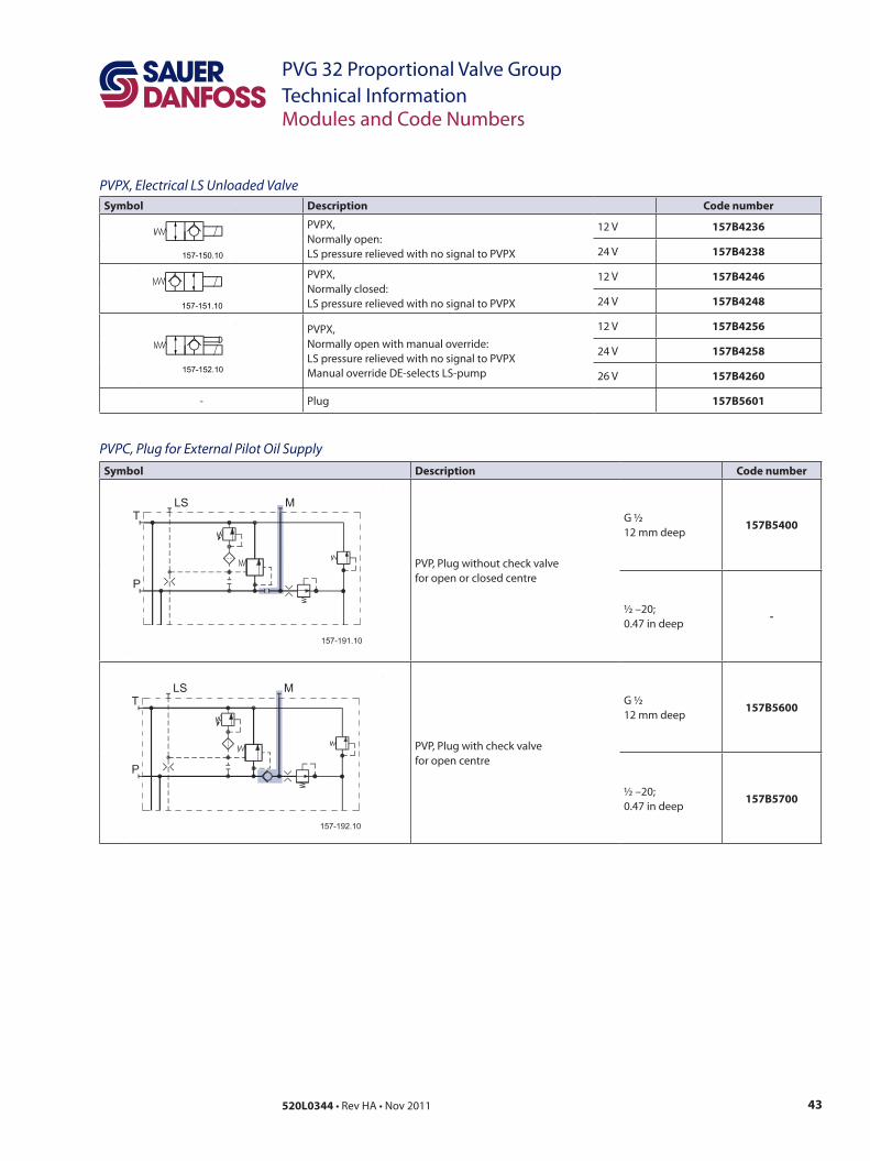
PVPX, Electrical LS Unloaded ValveSymbol Description Code number
PVPX, Normally open:LS pressure relieved with no signal to PVPX
12 V 157B4236
24 V 157B4238
PVPX, Normally closed:LS pressure relieved with no signal to PVPX
12 V 157B4246
24 V 157B4248
PVPX, Normally open with manual override:LS pressure relieved with no signal to PVPXManual override DE-selects LS-pump
12 V 157B4256
24 V 157B4258
26 V 157B4260
- Plug 157B5601
PVPC, Plug for External Pilot Oil SupplySymbol Description Code number
PVP, Plug without check valve for open or closed centre
G ½12 mm deep
157B5400
½ –20; 0.47 in deep
-
PVP, Plug with check valve for open centre
G ½12 mm deep
157B5600
½ –20; 0.47 in deep
157B5700
Modules and Code Numbers
44 520L0344 • Rev HA • Nov 2011
PVG 32 Proportional Valve GroupTechnical Information
General
PVP, Pump Side Module
Technical Characteristics
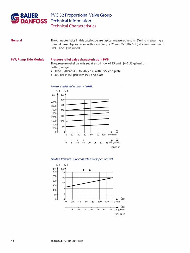
The characteristics in this catalogue are typical measured results. During measuring a mineral based hydraulic oil with a viscosity of 21 mm2/s [102 SUS] at a temperature of 50°C [122°F] was used.
Pressure relief valve characteristic in PVPThe pressure relief valve is set at an oil flow of 15 l/min [4.0 US gal/min]. Setting range: • 30 to 350 bar [435 to 5075 psi] with PVSI end plate• 300 bar [4351 psi] with PVS end plate
Pressure relief valve characteristic
Neutral flow pressure characteristic (open centre)
45520L0344 • Rev HA • Nov 2011
PVG 32 Proportional Valve GroupTechnical Information
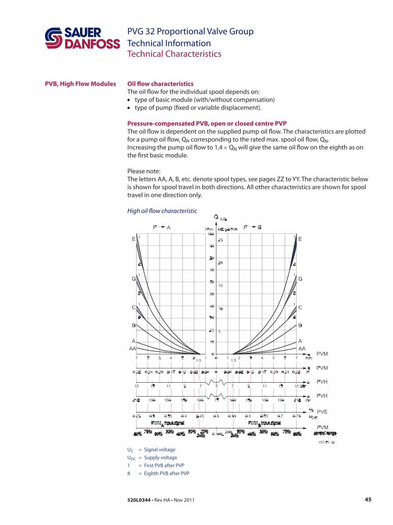
Oil flow characteristicsThe oil flow for the individual spool depends on:• type of basic module (with/without compensation)• type of pump (fixed or variable displacement).
Pressure-compensated PVB, open or closed centre PVPThe oil flow is dependent on the supplied pump oil flow. The characteristics are plotted for a pump oil flow, QP, corresponding to the rated max. spool oil flow, QN. Increasing the pump oil flow to 1,4 × QN will give the same oil flow on the eighth as on the first basic module.
Please note:The letters AA, A, B, etc. denote spool types, see pages ZZ to YY. The characteristic belowis shown for spool travel in both directions. All other characteristics are shown for spooltravel in one direction only.
High oil flow characteristic
PVB, High Flow Modules
Technical Characteristics
US = Signal voltage UDC = Supply voltage 1 = First PVB after PVP 8 = Eighth PVB after PVP

46 520L0344 • Rev HA • Nov 2011
PVG 32 Proportional Valve GroupTechnical Information
For PVB basic modules without pressure compensator the top ends of the characteristics (max. oil flow) are different so they correspond to those of the standard flow control spools, see characteristics for PVB without pressure compensator.
Linear characteristic
Technical Characteristics
US = Signal voltage UDC = Supply voltage 1 = First PVB after PVP 8 = Eighth PVB after PVP
PVB, Basic Modules
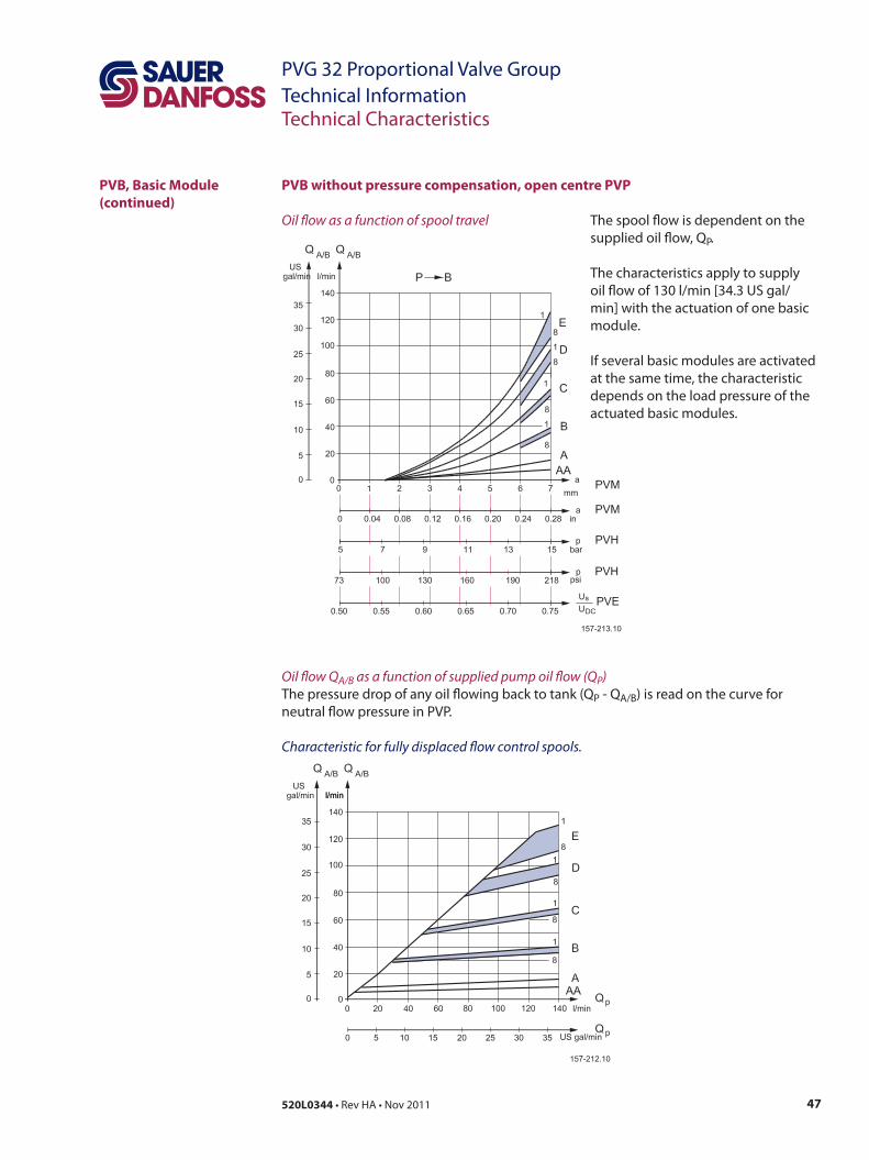
47520L0344 • Rev HA • Nov 2011
PVG 32 Proportional Valve GroupTechnical Information
PVB without pressure compensation, open centre PVP
Oil flow as a function of spool travel
Technical Characteristics
Oil flow QA/B as a function of supplied pump oil flow (QP) The pressure drop of any oil flowing back to tank (QP - QA/B) is read on the curve for neutral flow pressure in PVP.
Characteristic for fully displaced flow control spools.
PVB, Basic Module (continued)
The spool flow is dependent on the supplied oil flow, QP.
The characteristics apply to supply oil flow of 130 l/min [34.3 US gal/min] with the actuation of one basic module.
If several basic modules are activated at the same time, the characteristic depends on the load pressure of the actuated basic modules.
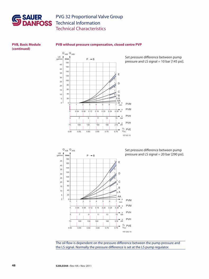
48 520L0344 • Rev HA • Nov 2011
PVG 32 Proportional Valve GroupTechnical InformationTechnical Characteristics
PVB, Basic Module (continued)
PVB without pressure compensation, closed centre PVP
The oil flow is dependent on the pressure difference between the pump pressure and the LS signal. Normally the pressure difference is set at the LS pump regulator.
Set pressure difference between pump pressure and LS signal = 10 bar [145 psi].
Set pressure difference between pump pressure and LS signal = 20 bar [290 psi].
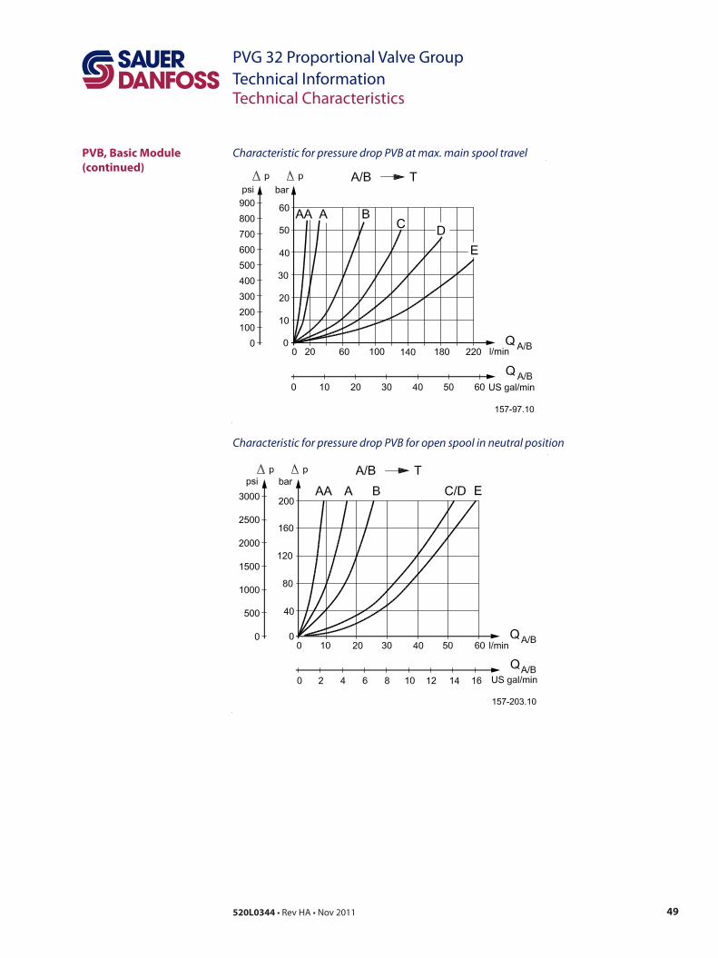
49520L0344 • Rev HA • Nov 2011
PVG 32 Proportional Valve GroupTechnical InformationTechnical Characteristics
Characteristic for pressure drop PVB at max. main spool travel PVB, Basic Module (continued)
Characteristic for pressure drop PVB for open spool in neutral position
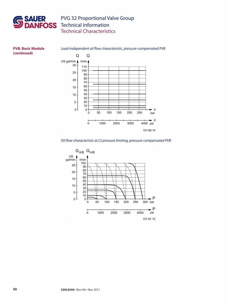
50 520L0344 • Rev HA • Nov 2011
PVG 32 Proportional Valve GroupTechnical Information
Load-independent oil flow characteristic, pressure-compensated PVB
Oil flow characteristic at LS pressure limiting, pressure-compensated PVB
Technical Characteristics
PVB, Basic Module (continued)
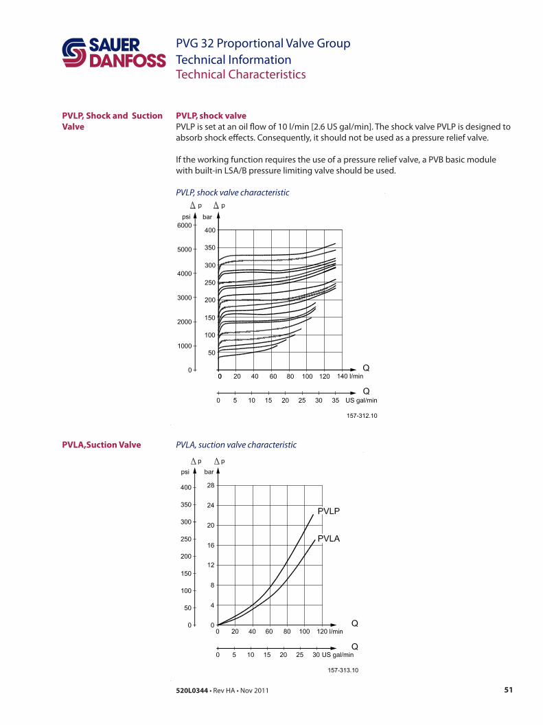
51520L0344 • Rev HA • Nov 2011
PVG 32 Proportional Valve GroupTechnical Information
PVLP, Shock and Suction Valve
PVLA,Suction Valve
Technical Characteristics
PVLP, shock valve PVLP is set at an oil flow of 10 l/min [2.6 US gal/min]. The shock valve PVLP is designed to absorb shock effects. Consequently, it should not be used as a pressure relief valve.
If the working function requires the use of a pressure relief valve, a PVB basic module with built-in LSA/B pressure limiting valve should be used.
PVLP, shock valve characteristic
PVLA, suction valve characteristic
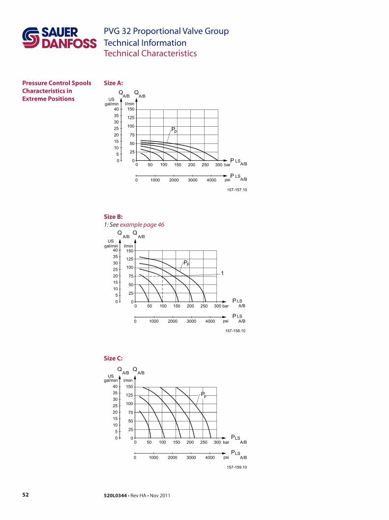
52 520L0344 • Rev HA • Nov 2011
PVG 32 Proportional Valve GroupTechnical Information
Pressure Control Spools Characteristics in Extreme Positions
Technical Characteristics
Size A:
Size B:1: See example page 46
Size C:
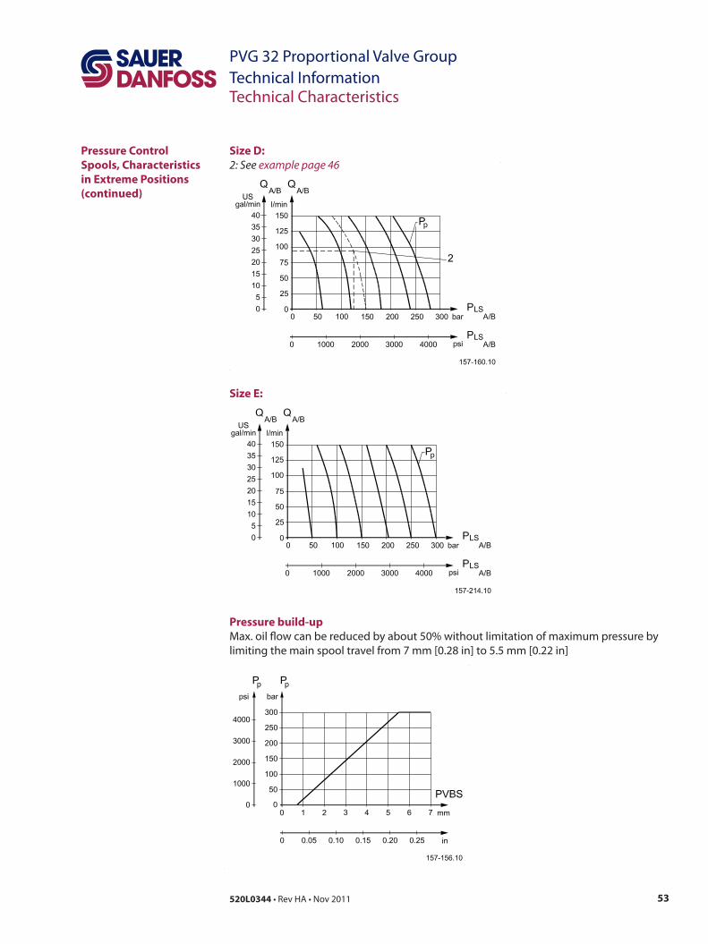
53520L0344 • Rev HA • Nov 2011
PVG 32 Proportional Valve GroupTechnical InformationTechnical Characteristics
Size D:2: See example page 46
Pressure Control Spools, Characteristics in Extreme Positions (continued)
Size E:
Pressure build-upMax. oil flow can be reduced by about 50% without limitation of maximum pressure by limiting the main spool travel from 7 mm [0.28 in] to 5.5 mm [0.22 in]

54 520L0344 • Rev HA • Nov 2011
PVG 32 Proportional Valve GroupTechnical Information
Examples of How To Use the Characteristics for Pressure Control Spools
Technical Characteristics
Example of determining the oil flow• Given:
– Spool type B– Pressure setting PP: 160 bar [2320 psi]– Load pressure, LSA/B: 100 bar [1450 psi]
• Result:– Oil flow = 75 l/min [19.8 US gal/min] (see page 45, size B).
Example of determining spool size• Given:
– Max. oil flow, QA/B: 90 l/min [23.8 US gal/min]– Pressure setting PP: 150 bar [2175 psi]– Load pressure, PLSA
: 125 bar [1810 psi]• Result:
– D spool (see page 45, size D)
Normally a smaller spool can be chosen with pressure control. It is our experience that the spool can be one size smaller than with normal flow control.
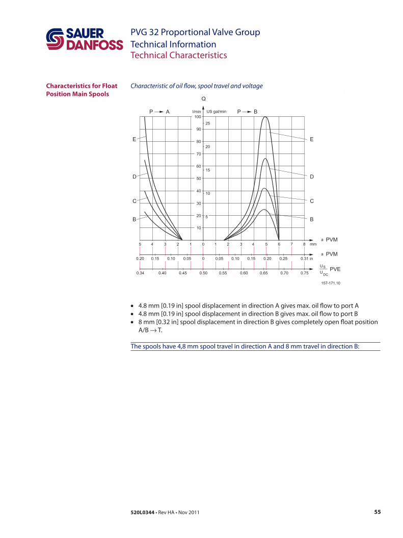
55520L0344 • Rev HA • Nov 2011
PVG 32 Proportional Valve GroupTechnical Information
Characteristic of oil flow, spool travel and voltageCharacteristics for Float Position Main Spools
Technical Characteristics
• 4.8 mm [0.19 in] spool displacement in direction A gives max. oil flow to port A• 4.8 mm [0.19 in] spool displacement in direction B gives max. oil flow to port B• 8 mm [0.32 in] spool displacement in direction B gives completely open float position
A/B → T.
The spools have 4,8 mm spool travel in direction A and 8 mm travel in direction B:
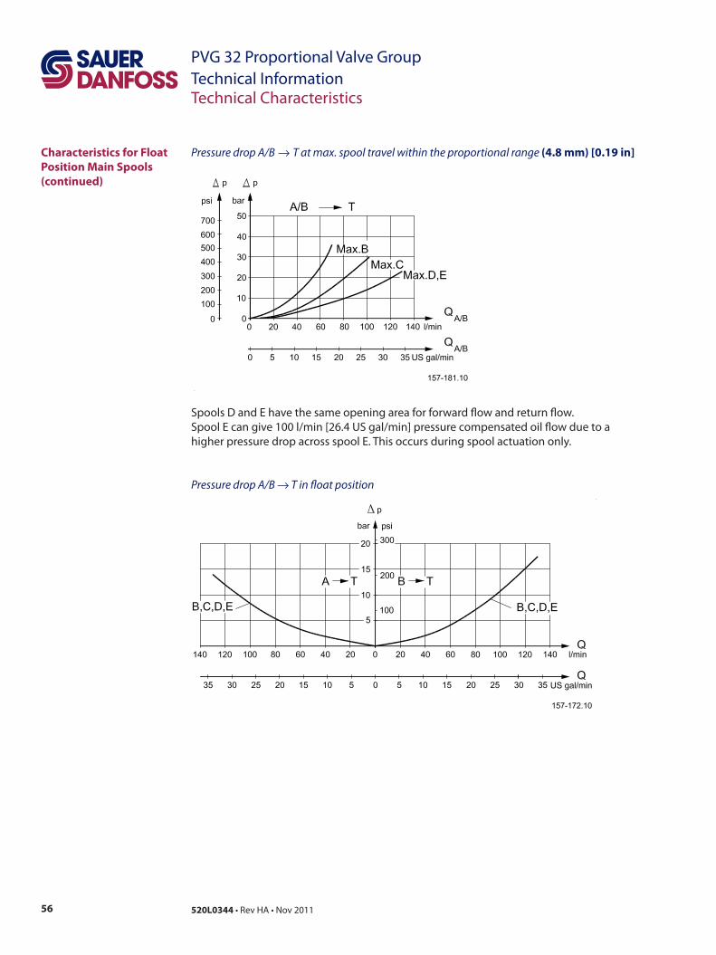
56 520L0344 • Rev HA • Nov 2011
PVG 32 Proportional Valve GroupTechnical Information
Characteristics for Float Position Main Spools (continued)
Technical Characteristics
Pressure drop A/B → T in float position
Pressure drop A/B → T at max. spool travel within the proportional range (4.8 mm) [0.19 in]
Spools D and E have the same opening area for forward flow and return flow. Spool E can give 100 l/min [26.4 US gal/min] pressure compensated oil flow due to a higher pressure drop across spool E. This occurs during spool actuation only.

57520L0344 • Rev HA • Nov 2011
PVG 32 Proportional Valve GroupTechnical Information
Dimensions
Dimensions
F: Shock and suction valve, PVLP G: Pressure gauge connection; G 1/4, 12 mm deep – [1/2 in-20, 0.47 in deep] H: Plug for external pilot oil supply, PVPC; G 1/2, 12 mm deep – [1/2 in-20, 0.47 in deep] I: Electrical LS unloading valve, PVPX J: LS connection; G 1/4, 12 mm deep – [1/2 in-20, 0.47 in deep] K: Fixing holes; M8 × min. 10 – [5/16 in-18, 0.47 in deep] L: Port A and B; G 1/2, 14 mm deep – [7/8 in-14, 0.65 in deep] M: LX connection: PVS; G 1/8, 10 mm deep – [3/8 in-24, 0.39 in deep] and PVSI; G 1/4, 12 mm [0.47 in] deep – [1/2 in-20, 0.47 in deep] N: LS pressure limiting valve O: Tank connection; G 3/4, 16 mm deep – [1 1/16 in-12, 0.75 in deep] P: Pressure relief valve Q: Pump connection; G 1/2, 14 mm deep or G 3/4, 16 mm deep – [7/8 in-14, 0.65 in deep or 1 1/16 in-12, 0.75 in deep] R: LSA and LSB connections; G 1/4, 12 mm [0.47 in] deep – [1/2 in-20, 0.47 in deep] S : Pp, pilot pressure connection G ¼
S
37[1.46]
V310140.A
48[1
.89]
PVS=
11.5
[0.4
53]
P
95[3.74]
L2
T
LS
P
112.
5[4.
430]
115.
5[4.
457]
22.5°
34.5[1.358]79.5[3.130]
95[3.74]58.5[2.303]
141[
5.55
]70
.5[2
.776
]38
.5[1
.516
]
22[0
.87]
1L
35[1.38]
21[1.118]36.5[1.437]36[1.42]
69.5[2.736]24[0
.94]
23[0
.91]
48[1
.89]
12[0
.47]16
.5[0
.650
]
B4A4
B3A3
B2A2
B1A1
C
B
A
C
B
A
85.5[3.366]
23[0
.91]
37[1
.46]
38.5
[1.5
16]
38.5[1.516]
23[0
.91]
PVSI
=12[
0.47
]R
F G H
KJI
M LN
O
Q
PVB 1 2 3 4 5 6 7 8 9 10 11 12
L1mm 82 130 178 226 274 322 370 418 466 514 562 610[in] [3.23] [5.12] [7.01] [8.90] [10.79] [12.68] [14.57] [16.46] [18.35] [20.24] [562] [610]
L2mm 140 189 238 287 336 385 434 483 527 576 622 670in] [5.51] [7.44] [9.37] [11.30] [13.23] [15.16] [17.09] [19.02] [20.95] [22.87] [622] [670]

58 520L0344 • Rev HA • Nov 2011
PVG 32 Proportional Valve GroupTechnical Information
Dimensions (continued)
Dimensions
F : G 1/4, 12 mm deep [1/2 in - 20, 0.47 in deep]
F
max.290.50[11.437]
107[4.21]max.290.50[11.437]
129[
5.08
]95
[3.7
4]7[
0.28
]
M
85[3
.35]
17[0.67]
A-A
110[4.33] 60[2.36]
PV
D85[3
.35]
58.5
[2.3
03] 32
[1.2
6]6.
5[0.
256]
33[1.30]7[
0.28
]max.200.5[7.894]
13[0
.51]
110[4.33]
B-B
60[2.36]
110[4.33]
C-C
60[2.36]
7[0.
28]
45[1
.77]
7[0.
28]
49.5[1.949]
PVMR/F
107[4.21]
117[
4.61
]
139[
5.47
2]
~ 16
5[6.
50]
44 [1
.732
]
89.5[3.524]
85.5[3.366]
PVEO
PVEM/PVEH/
PVH
V310141.A
PVES
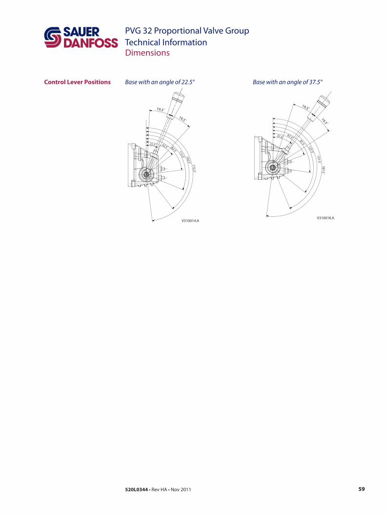
59520L0344 • Rev HA • Nov 2011
PVG 32 Proportional Valve GroupTechnical Information
Control Lever Positions Base with an angle of 22.5°
22.5˚ 52.5˚ 82.5˚ 112.5˚ 142.5˚ 172.5˚
19.5˚
19.5˚
V310014.A
37.5˚67.5˚
97.5˚ 127.5˚
157.5˚187.5˚
19.5˚
19.5˚
V310018.A
Base with an angle of 37.5°
Dimensions
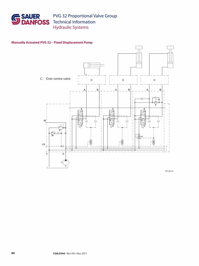
60 520L0344 • Rev HA • Nov 2011
PVG 32 Proportional Valve GroupTechnical Information
Manually Actuated PVG 32 – Fixed Displacement Pump
Hydraulic Systems
C: Over-centre valve

61520L0344 • Rev HA • Nov 2011
PVG 32 Proportional Valve GroupTechnical Information
Electrically Actuated PVG 32 – Variable Displacement Pump (Electrical Actuator, Shock Valves, etc.)
Hydraulic Systems
62 520L0344 • Rev HA • Nov 2011
PVG 32 Proportional Valve GroupTechnical Information
Oil
Particle Content, Degree of Contamination
Other Operating Conditions
The main duty of the oil in a hydraulic system is to transfer energy; but it must also lubricate the moving parts in hydraulic components, protect them against corrosion, and transport dirt particles and heat out of the system. It is therefore important to choose the correct oil with the correct additives. This gives normal operation and long working life.
Mineral oilFor systems with PVG 32 valves Sauer-Danfoss recommends the use of mineral-based hydraulic oil containing additives: Type HLP (DIN 51524) or HM (ISO 6743/4).
Non-flammable fluidsPhosphate-esters (HFDR fluids) can be used without special precautions. However, dynamic seals must be replaced with FPM (Viton) seals. So please contact the Sauer-Danfoss Sales Organization if the PVG 32 valve is to be used with phosphate-esters.The following fluids should only be used according to agreement with the Sales Organization for Sauer-Danfoss:• Water-glycol mixtures (HFC fluids)• Water-oil emulsions (HFB fluids)• Oil-water emulsions (HFAE fluids)
Biodegradable oilsPVG 32 valves can be used in systems with rapeseed oil. The use of rapeseed oil is conditioned by• complying with the demands on viscosity, water content, temperature and filtering
etc. (see chapters below and technical data page 14).• adapting the operating conditions to the directions of the oil supplier.
Before using other biodegradable fluids, please consult the Sauer-Danfoss Organization.
Oil filtration must prevent particle content from exceeding an acceptable level, i.e. an acceptable degree of contamination.
Maximum contamination for PVG 32 is 23/19/16 (see ISO 4406. Calibration in accordance with the ACFTD method).
In our experience a degree of contamination of 23/19/16 can be maintained by using a filter fineness as described in the next section.
For more information, please see the Sauer-Danfoss literature: • Design Guidelines for Hydraulic Fluid Cleanliness Technical Information, 520L0467• Hydraulic Fluids and Lubricants Technical Information, 521L0463 and • Experience with Bio-Hydraulic Fluids Technical Information, 521L0465.
63520L0344 • Rev HA • Nov 2011
PVG 32 Proportional Valve GroupTechnical Information
Filtration
Other Operating Conditions
Effective filtration is the most important precondition in ensuring that a hydraulic system performs reliably and has a long working life. Filter manufacturers issue instructions and recommendations. It is advisable to follow them.
System filtersWhere demands on safety and reliability are very high a pressure filter with bypass and indicator is recommended. Experience shows that a 10 µm nominal filter (or finer) or a 20 µm absolute filter (or finer) is suitable.It is our experience that a return filter is adequate in a purely mechanically operated valve system.
The fineness of a pressure filter must be selected as described by the filter manufacturer so that a particle level of 23/19/16 is not exceeded.
The filter must be fitted with pressure gauge or dirt indicator to make it possible to check the condition of the filter.
In systems with differential cylinders or accumulators the return filter must be sized to suit the max. return oil flow. Pressure filters must be fitted to suit max. pump oil flow.
Internal filtersThe filters built into PVG 32 are not intended to filter the system but to protect important components against large particles. Such particles can appear in the system as a result of pump damage, hose fracture, use of quick-couplings, filter damage, starting up, contamination, etc.
The filter in the electrical actuator PVE protecting the solenoid valves has a mesh of 150 µm.
Bursting pressure drop for internal filters is 25 bar [360 psi].
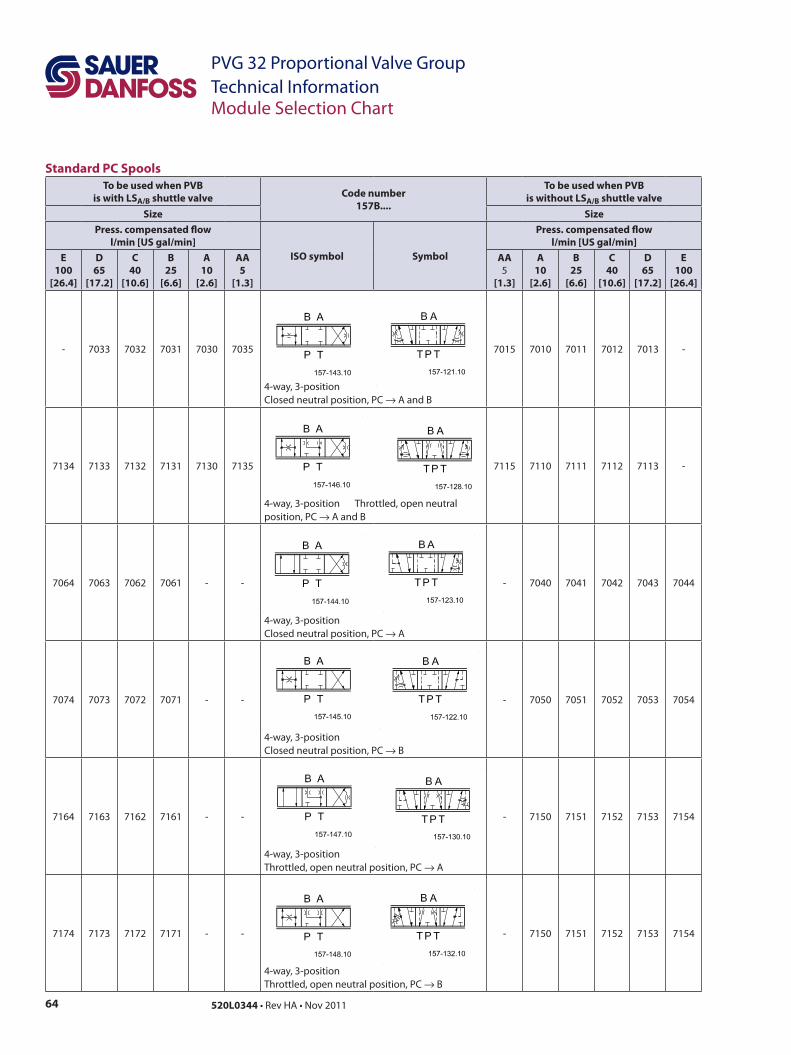
64 520L0344 • Rev HA • Nov 2011
PVG 32 Proportional Valve GroupTechnical Information
Standard PC Spools To be used when PVB
is with LSA/B shuttle valve Code number157B....
To be used when PVBis without LSA/B shuttle valve
Size SizePress. compensated flow
l/min [US gal/min]ISO symbol Symbol
Press. compensated flowl/min [US gal/min]
E100
[26.4]
D65
[17.2]
C40
[10.6]
B25
[6.6]
A10
[2.6]
AA5
[1.3]
AA5
[1.3]
A10
[2.6]
B25
[6.6]
C40
[10.6]
D65
[17.2]
E100
[26.4]
- 7033 7032 7031 7030 7035
4-way, 3-positionClosed neutral position, PC → A and B
7015 7010 7011 7012 7013 -
7134 7133 7132 7131 7130 7135
4-way, 3-position Throttled, open neutral position, PC → A and B
7115 7110 7111 7112 7113 -
7064 7063 7062 7061 - -
4-way, 3-position Closed neutral position, PC → A
- 7040 7041 7042 7043 7044
7074 7073 7072 7071 - -
4-way, 3-position Closed neutral position, PC → B
- 7050 7051 7052 7053 7054
7164 7163 7162 7161 - -
4-way, 3-position Throttled, open neutral position, PC → A
- 7150 7151 7152 7153 7154
7174 7173 7172 7171 - -
4-way, 3-position Throttled, open neutral position, PC → B
- 7150 7151 7152 7153 7154
Module Selection Chart
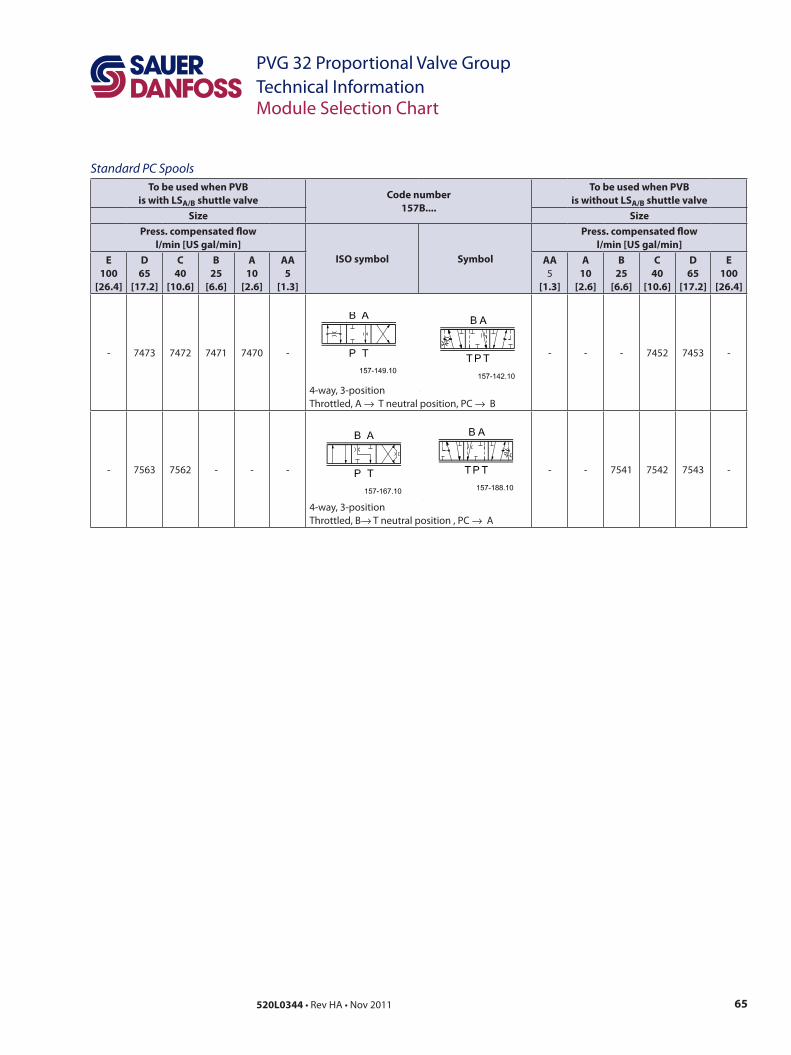
65520L0344 • Rev HA • Nov 2011
PVG 32 Proportional Valve GroupTechnical Information
Standard PC Spools To be used when PVB
is with LSA/B shuttle valve Code number157B....
To be used when PVB is without LSA/B shuttle valve
Size SizePress. compensated flow
l/min [US gal/min]ISO symbol Symbol
Press. compensated flowl/min [US gal/min]
E100
[26.4]
D65
[17.2]
C40
[10.6]
B25
[6.6]
A10
[2.6]
AA5
[1.3]
AA5
[1.3]
A10
[2.6]
B25
[6.6]
C40
[10.6]
D65
[17.2]
E100
[26.4]
- 7473 7472 7471 7470 -
4-way, 3-position Throttled, A → T neutral position, PC → B
- - - 7452 7453 -
- 7563 7562 - - -
4-way, 3-position Throttled, B→ T neutral position , PC → A
- - 7541 7542 7543 -
Module Selection Chart
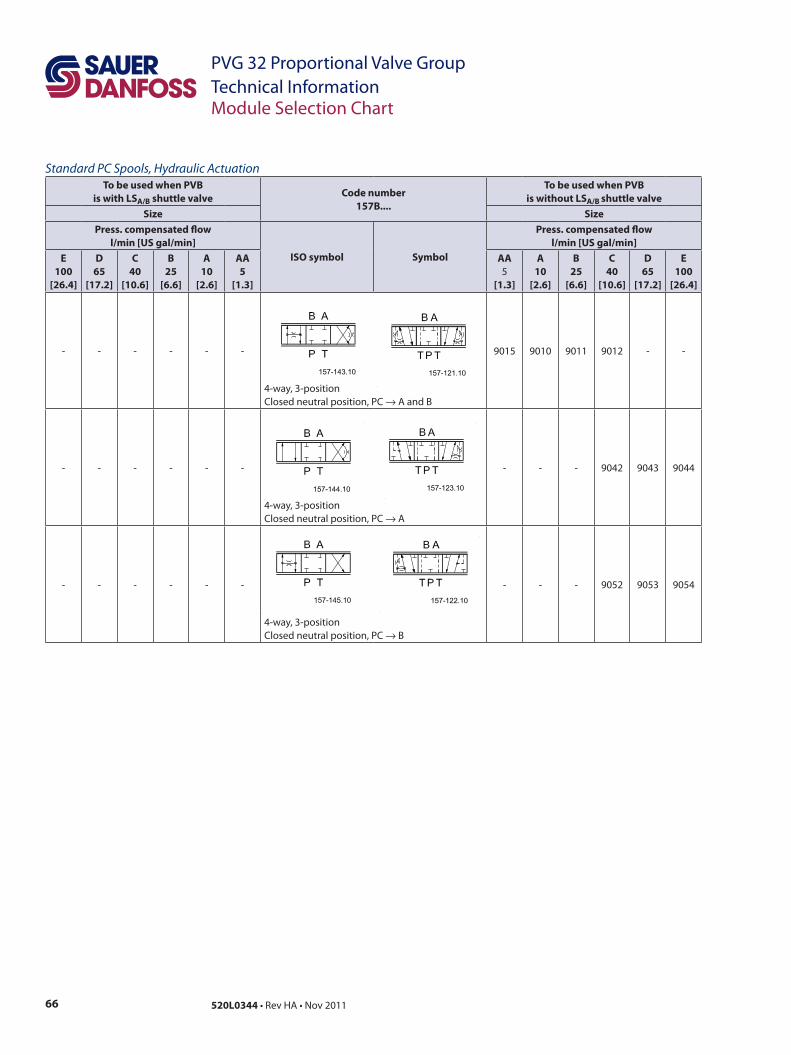
66 520L0344 • Rev HA • Nov 2011
PVG 32 Proportional Valve GroupTechnical Information
Standard PC Spools, Hydraulic ActuationTo be used when PVB
is with LSA/B shuttle valve Code number157B....
To be used when PVB is without LSA/B shuttle valve
Size SizePress. compensated flow
l/min [US gal/min]ISO symbol Symbol
Press. compensated flow l/min [US gal/min]
E100
[26.4]
D65
[17.2]
C40
[10.6]
B25
[6.6]
A10
[2.6]
AA5
[1.3]
AA5
[1.3]
A10
[2.6]
B25
[6.6]
C40
[10.6]
D65
[17.2]
E100
[26.4]
- - - - - -
4-way, 3-position Closed neutral position, PC → A and B
9015 9010 9011 9012 - -
- - - - - -
4-way, 3-position Closed neutral position, PC → A
- - - 9042 9043 9044
- - - - - -
4-way, 3-position Closed neutral position, PC → B
- - - 9052 9053 9054
Module Selection Chart
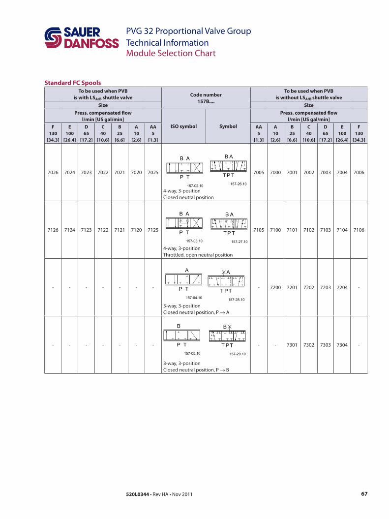
67520L0344 • Rev HA • Nov 2011
PVG 32 Proportional Valve GroupTechnical Information
Standard FC SpoolsTo be used when PVB
is with LSA/B shuttle valve Code number157B....
To be used when PVB is without LSA/B shuttle valve
Size SizePress. compensated flow
l/min [US gal/min]ISO symbol Symbol
Press. compensated flow l/min [US gal/min]
F130
[34.3]
E100
[26.4]
D65
[17.2]
C40
[10.6]
B25
[6.6]
A10
[2.6]
AA5
[1.3]
AA5
[1.3]
A10
[2.6]
B25
[6.6]
C40
[10.6]
D65
[17.2]
E100
[26.4]
F130
[34.3]
7026 7024 7023 7022 7021 7020 7025
4-way, 3-position Closed neutral position
7005 7000 7001 7002 7003 7004 7006
7126 7124 7123 7122 7121 7120 7125
4-way, 3-position Throttled, open neutral position
7105 7100 7101 7102 7103 7104 7106
- - - - - - -
3-way, 3-position Closed neutral position, P → A
- 7200 7201 7202 7203 7204 -
- - - - - - -
3-way, 3-position Closed neutral position, P → B
- - 7301 7302 7303 7304 -
Module Selection Chart
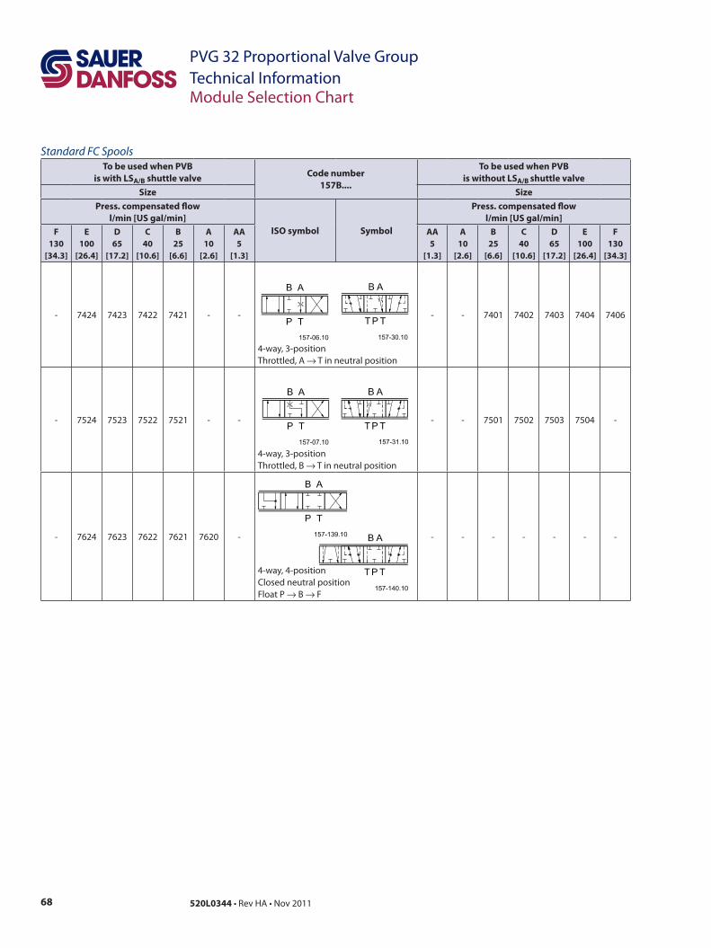
68 520L0344 • Rev HA • Nov 2011
PVG 32 Proportional Valve GroupTechnical Information
Standard FC SpoolsTo be used when PVB
is with LSA/B shuttle valve Code number157B....
To be used when PVB is without LSA/B shuttle valve
Size SizePress. compensated flow
l/min [US gal/min]ISO symbol Symbol
Press. compensated flow l/min [US gal/min]
F130
[34.3]
E100
[26.4]
D65
[17.2]
C40
[10.6]
B25
[6.6]
A10
[2.6]
AA5
[1.3]
AA5
[1.3]
A10
[2.6]
B25
[6.6]
C40
[10.6]
D65
[17.2]
E100
[26.4]
F130
[34.3]
- 7424 7423 7422 7421 - -
4-way, 3-position Throttled, A → T in neutral position
- - 7401 7402 7403 7404 7406
- 7524 7523 7522 7521 - -
4-way, 3-position Throttled, B → T in neutral position
- - 7501 7502 7503 7504 -
- 7624 7623 7622 7621 7620 -
4-way, 4-position Closed neutral position Float P → B → F
- - - - - - -
Module Selection Chart
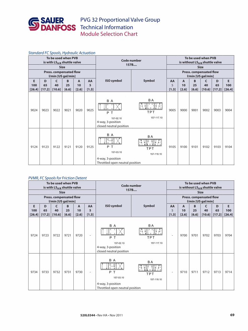
69520L0344 • Rev HA • Nov 2011
PVG 32 Proportional Valve GroupTechnical Information
Standard FC Spools, Hydraulic ActuationTo be used when PVB
is with LSA/B shuttle valve Code number157B....
To be used when PVB is without LSA/B shuttle valve
Size SizePress. compensated flow
l/min [US gal/min]ISO symbol Symbol
Press. compensated flow l/min [US gal/min]
E100
[26.4]
D65
[17.2]
C40
[10.6]
B25
[6.6]
A10
[2.6]
AA5
[1.3]
AA5
[1.3]
A10
[2.6]
B25
[6.6]
C40
[10.6]
D65
[17.2]
E100
[26.4]
9024 9023 9022 9021 9020 9025
4-way, 3-position closed neutral position
9005 9000 9001 9002 9003 9004
9124 9123 9122 9121 9120 9125
4-way, 3-position Throttled open neutral position
9105 9100 9101 9102 9103 9104
PVMR, FC Spools for Friction DetentTo be used when PVB
is with LSA/B shuttle valve Code number157B....
To be used when PVB is without LSA/B shuttle valve
Size SizePress. compensated flow
l/min [US gal/min]ISO symbol Symbol
Press. compensated flow l/min [US gal/min]
E100
[26.4]
D65
[17.2]
C40
[10.6]
B25
[6.6]
A10
[2.6]
AA5
[1.3]
AA5
[1.3]
A10
[2.6]
B25
[6.6]
C40
[10.6]
D65
[17.2]
E100
[26.4]
9724 9723 9722 9721 9720 -
4-way, 3-position closed neutral position
- 9700 9701 9702 9703 9704
9734 9733 9732 9731 9730 -
4-way, 3-position Throttled open neutral position
- 9710 9711 9712 9713 9714
Module Selection Chart
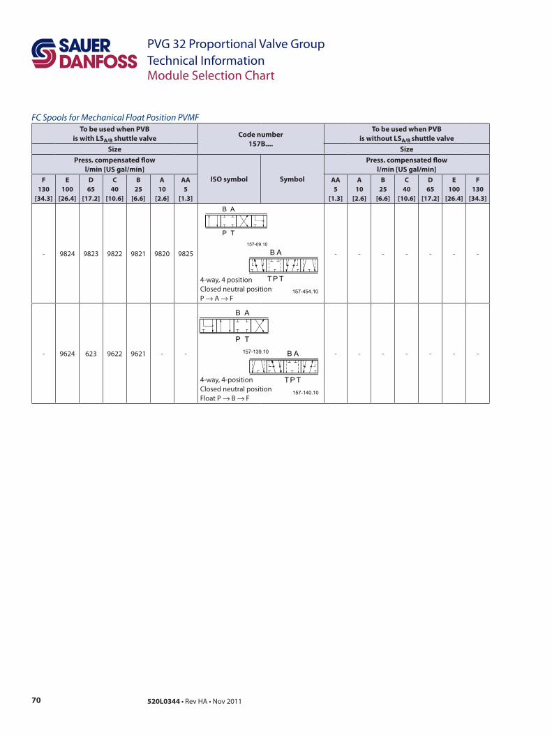
70 520L0344 • Rev HA • Nov 2011
PVG 32 Proportional Valve GroupTechnical Information
FC Spools for Mechanical Float Position PVMFTo be used when PVB
is with LSA/B shuttle valve Code number157B....
To be used when PVB is without LSA/B shuttle valve
Size SizePress. compensated flow
l/min [US gal/min]ISO symbol Symbol
Press. compensated flow l/min [US gal/min]
F130
[34.3]
E100
[26.4]
D65
[17.2]
C40
[10.6]
B25
[6.6]
A10
[2.6]
AA5
[1.3]
AA5
[1.3]
A10
[2.6]
B25
[6.6]
C40
[10.6]
D65
[17.2]
E100
[26.4]
F130
[34.3]
- 9824 9823 9822 9821 9820 9825
4-way, 4 position Closed neutral position P → A → F
- - - - - - -
- 9624 623 9622 9621 - -
4-way, 4-position Closed neutral position Float P → B → F
- - - - - - -
Module Selection Chart

71520L0344 • Rev HA • Nov 2011
PVG 32 Proportional Valve GroupTechnical Information
FC Spools with Linear Flow Characteristic To be used when PVB
is with LSA/B shuttle valve Code number157B....
To be used when PVB is without LSA/B shuttle valve
Size SizePress. compensated flow
l/min [US gal/min]ISO symbol Symbol
Press. compensated flow l/min [US gal/min]
F130
[34.3]
E100
[26.4]
D65
[17.2]
C40
[10.6]
B25
[6.6]
A10
[2.6]
AA5
[1.3]
AA5
[1.3]
A10
[2.6]
B25
[6.6]
C40
[10.6]
D65
[17.2]
E100
[26.4]
F130
[34.3]
- 9774 9773 9772 9771 - -
4-way, 3-position Closed neutral position
- 9750 9751 9752 9753 9754 -
- 9784 9783 9782 9781 - -
4-way, 3-position Throttled, open neutral position
- 9760 9761 9762 9763 9764 -
- - - - - - -
4-way, 3-position Throttled, A → T in neutral position
- - - - - 9794 -
- - - - - - -
4-way, 3-position B → T in neutral position
- - - - - 9804 -
Module Selection Chart
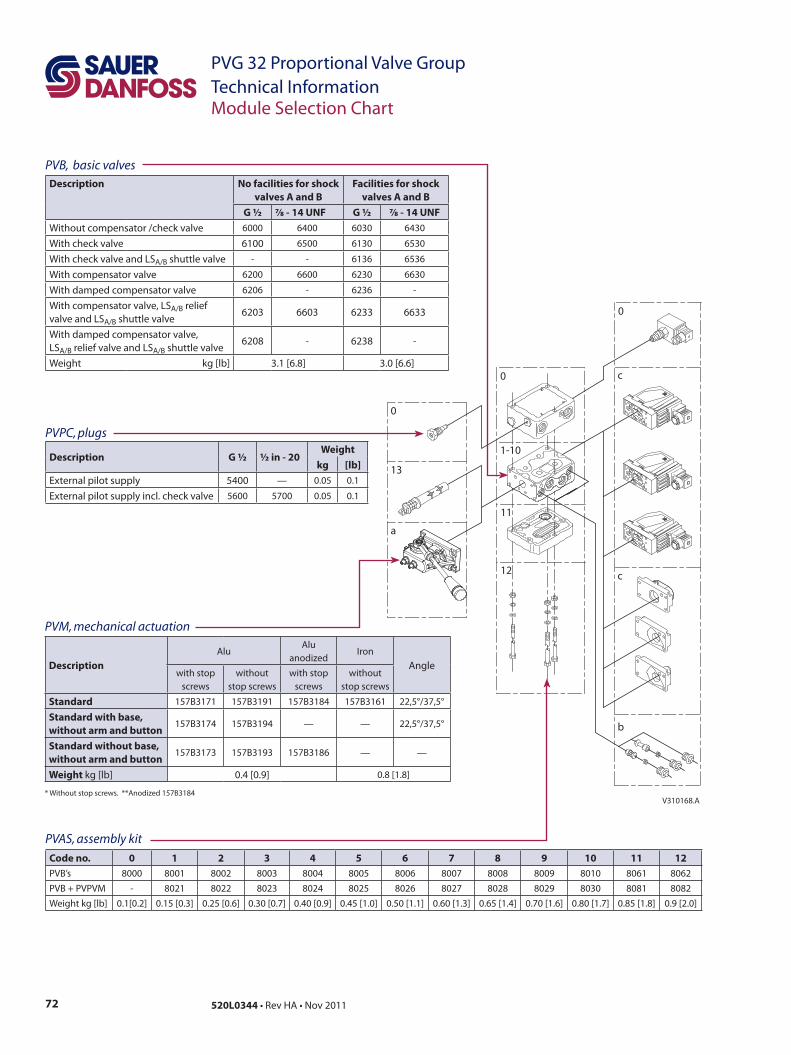
72 520L0344 • Rev HA • Nov 2011
PVG 32 Proportional Valve GroupTechnical InformationModule Selection Chart
V310168.A
0
13
a
0
11
12
0
c
c
b
1-10
PVAS, assembly kit
Code no. 0 1 2 3 4 5 6 7 8 9 10 11 12PVB’s 8000 8001 8002 8003 8004 8005 8006 8007 8008 8009 8010 8061 8062
PVB + PVPVM - 8021 8022 8023 8024 8025 8026 8027 8028 8029 8030 8081 8082
Weight kg [lb] 0.1[0.2] 0.15 [0.3] 0.25 [0.6] 0.30 [0.7] 0.40 [0.9] 0.45 [1.0] 0.50 [1.1] 0.60 [1.3] 0.65 [1.4] 0.70 [1.6] 0.80 [1.7] 0.85 [1.8] 0.9 [2.0]
PVB, basic valvesDescription No facilities for shock
valves A and BFacilities for shock
valves A and BG ½ 7∕8 - 14 UNF G ½ 7∕8 - 14 UNF
Without compensator /check valve 6000 6400 6030 6430
With check valve 6100 6500 6130 6530
With check valve and LSA/B shuttle valve - - 6136 6536
With compensator valve 6200 6600 6230 6630
With damped compensator valve 6206 - 6236 -
With compensator valve, LSA/B relief valve and LSA/B shuttle valve
6203 6603 6233 6633
With damped compensator valve, LSA/B relief valve and LSA/B shuttle valve
6208 - 6238 -
Weight kg [lb] 3.1 [6.8] 3.0 [6.6]
PVPC, plugs
Description G ½ ½ in - 20Weight
kg [lb]External pilot supply 5400 — 0.05 0.1
External pilot supply incl. check valve 5600 5700 0.05 0.1
PVM, mechanical actuation
DescriptionAlu
Alu anodized
IronAngle
with stop screws
without stop screws
with stop screws
without stop screws
Standard 157B3171 157B3191 157B3184 157B3161 22,5°/37,5°
Standard with base, without arm and button
157B3174 157B3194 — — 22,5°/37,5°
Standard without base, without arm and button
157B3173 157B3193 157B3186 — —
Weight kg [lb] 0.4 [0.9] 0.8 [1.8]
* Without stop screws. **Anodized 157B3184
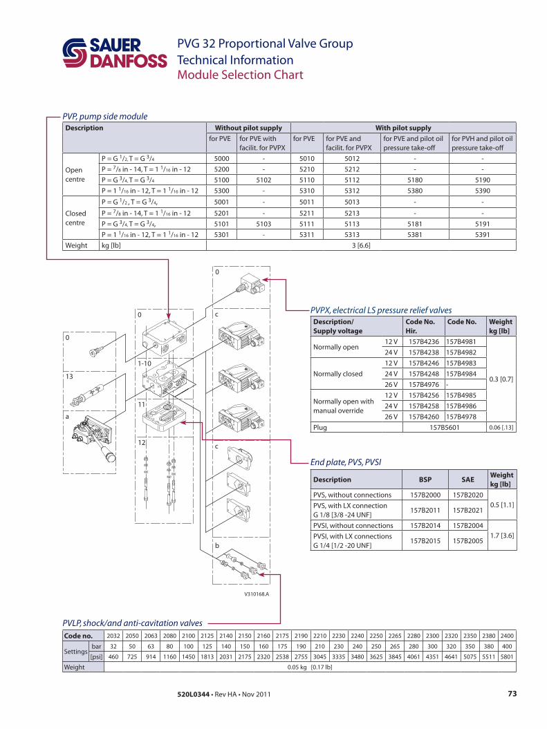
73520L0344 • Rev HA • Nov 2011
PVG 32 Proportional Valve GroupTechnical Information
End plate, PVS, PVSI
Description BSP SAEWeightkg [lb]
PVS, without connections 157B2000 157B20200.5 [1.1]PVS, with LX connection
G 1/8 [3/8 -24 UNF]157B2011 157B2021
PVSI, without connections 157B2014 157B20041.7 [3.6]PVSI, with LX connections
G 1/4 [1/2 -20 UNF]157B2015 157B2005
PVLP, shock/and anti-cavitation valvesCode no. 2032 2050 2063 2080 2100 2125 2140 2150 2160 2175 2190 2210 2230 2240 2250 2265 2280 2300 2320 2350 2380 2400
Settingsbar 32 50 63 80 100 125 140 150 160 175 190 210 230 240 250 265 280 300 320 350 380 400
[psi] 460 725 914 1160 1450 1813 2031 2175 2320 2538 2755 3045 3335 3480 3625 3845 4061 4351 4641 5075 5511 5801
Weight 0.05 kg [0.17 lb]
Module Selection Chart
V310168.A
0
13
a
0
11
12
0
c
c
b
1-10
PVP, pump side moduleDescription Without pilot supply With pilot supply
for PVE for PVE with facilit. for PVPX
for PVE for PVE and facilit. for PVPX
for PVE and pilot oil pressure take-off
for PVH and pilot oil pressure take-off
Open centre
P = G 1/2, T = G 3/4 5000 - 5010 5012 - -P = 7/8 in - 14, T = 1 1/16 in - 12 5200 - 5210 5212 - -P = G 3/4, T = G 3/4 5100 5102 5110 5112 5180 5190P = 1 1/16 in - 12, T = 1 1/16 in - 12 5300 - 5310 5312 5380 5390
Closed centre
P = G 1/2 , T = G 3/4, 5001 - 5011 5013 - -
P = 7/8 in - 14, T = 1 1/16 in - 12 5201 - 5211 5213 - -P = G 3/4, T = G 3/4, 5101 5103 5111 5113 5181 5191P = 1 1/16 in - 12, T = 1 1/16 in - 12 5301 - 5311 5313 5381 5391
Weight kg [lb] 3 [6.6]
PVPX, electrical LS pressure relief valvesDescription/Supply voltage
Code No. Hir.
Code No. Weightkg [lb]
Normally open12 V 157B4236 157B4981
0.3 [0.7]
24 V 157B4238 157B4982
Normally closed12 V 157B4246 157B498324 V 157B4248 157B498426 V 157B4976 -
Normally open with manual override
12 V 157B4256 157B498524 V 157B4258 157B498626 V 157B4260 157B4978
Plug 157B5601 0.06 [.13]
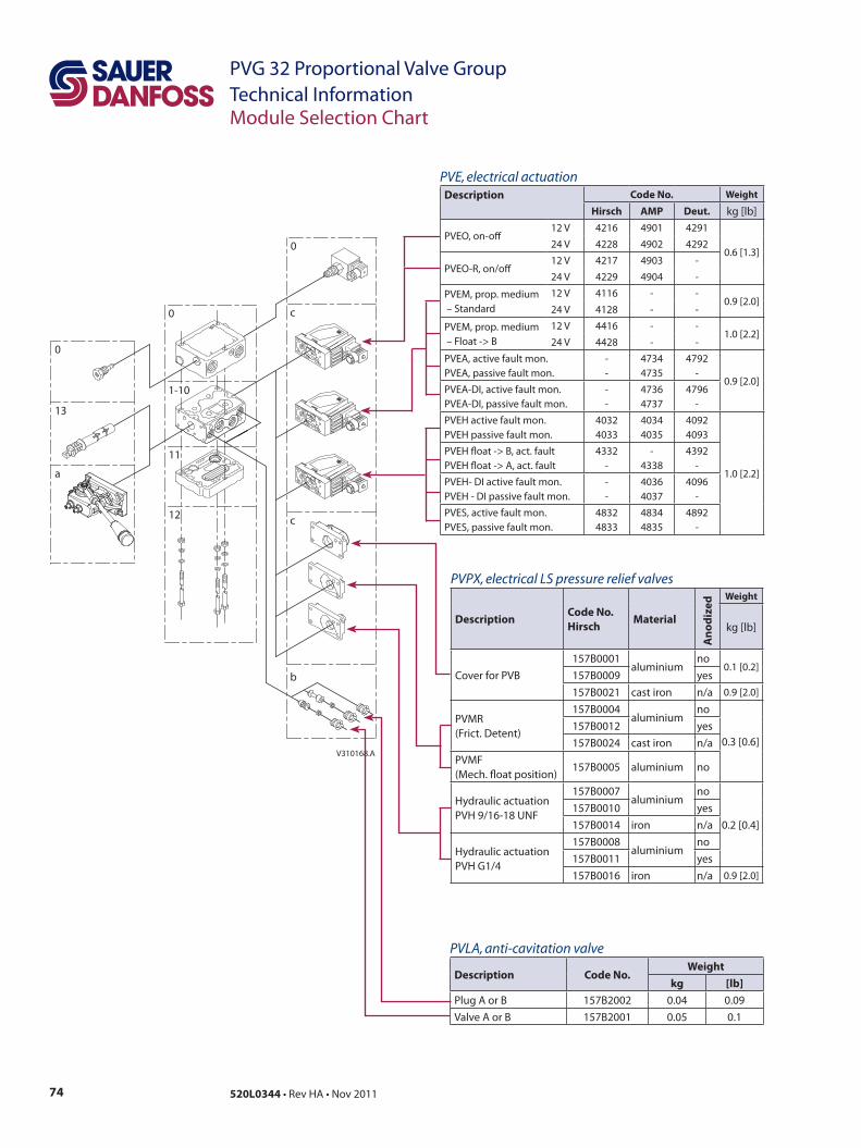
74 520L0344 • Rev HA • Nov 2011
PVG 32 Proportional Valve GroupTechnical InformationModule Selection Chart
V310168.A
0
13
a
0
11
12
0
c
c
b
1-10
PVE, electrical actuationDescription Code No. Weight
Hirsch AMP Deut. kg [lb]
PVEO, on-off12 V 4216 4901 4291
0.6 [1.3]24 V 4228 4902 4292
PVEO-R, on/off12 V 4217 4903 -
24 V 4229 4904 -
PVEM, prop. medium – Standard
12 V 4116 - -0.9 [2.0]
24 V 4128 - -
PVEM, prop. medium – Float -> B
12 V 4416 - -1.0 [2.2]
24 V 4428 - -
PVEA, active fault mon.PVEA, passive fault mon.
--
47344735
4792-
0.9 [2.0]PVEA-DI, active fault mon.PVEA-DI, passive fault mon.
--
47364737
4796-
PVEH active fault mon.PVEH passive fault mon.
40324033
40344035
40924093
1.0 [2.2]
PVEH float -> B, act. faultPVEH float -> A, act. fault
4332-
-4338
4392-
PVEH- DI active fault mon. PVEH - DI passive fault mon.
--
40364037
4096-
PVES, active fault mon. PVES, passive fault mon.
48324833
48344835
4892-
PVLA, anti-cavitation valve
Description Code No.Weight
kg [lb]Plug A or B 157B2002 0.04 0.09Valve A or B 157B2001 0.05 0.1
PVPX, electrical LS pressure relief valves
DescriptionCode No. Hirsch
Material
Ano
dize
d Weight
kg [lb]
Cover for PVB157B0001
aluminiumno
0.1 [0.2]157B0009 yes157B0021 cast iron n/a 0.9 [2.0]
PVMR (Frict. Detent)
157B0004aluminium
no
0.3 [0.6]157B0012 yes157B0024 cast iron n/a
PVMF (Mech. float position)
157B0005 aluminium no
Hydraulic actuation PVH 9/16-18 UNF
157B0007aluminium
no
0.2 [0.4]157B0010 yes157B0014 iron n/a
Hydraulic actuation PVH G1/4
157B0008aluminium
no157B0011 yes157B0016 iron n/a 0.9 [2.0]
75520L0344 • Rev HA • Nov 2011
PVG 32 Proportional Valve GroupTechnical Information
Order Specification
Order Specification
An order form for Sauer-Danfoss PVG 32 hydraulic valve is shown on the next page. The form can be obtained from the Sauer-Danfoss Sales Organization.
Both the module selection chart on the previous pages and the order form are divided into fields 0, 1-10, 11, 12, 13, a, b, and c.
Each module has its own field:0:
– Pump side module PVP – Plug for external pilot oil supply PVPC– Electrical LS unloading valve PVPX
1-10: Basic valves PVB13: Main spool PVBS a: Mechanical actuator PVM (or PVE when option mounted)c:
– Cover for mechanical actuation PVMD– Cover for hydraulic actuation PVH – Electrical actuators PVE (or PVM when option mounted)
b:– Shock and suction valve PVLP – Suction valve PVLA
11: End plate PVS 12: Assembly kit PVAS
Please state– Code numbers of all modules required– Required setting (P) for pump side module– Required setting of LSA/B pressure limiting valves,
see pressure setting guidance below.
Standard and option assemblyThe PVG 32 valve group is assembled the way the module selection chart shows if the code number for PVM is written in field a, and the code number for PVMD, PVE or PVH in field c.The valve group is assembled so that the mechanical actuator is mounted on the opposite end of the basic module, if the code number for PVM is written in field c of the order form and the code numbers for PVMD, PVE or PVH in field a.
ReorderingThe space at the top right-hand corner of the form is for Sauer-Danfoss to fill in. The code number for the whole of the specified valve group (PVG No.) is entered here. In the event of a repeat order all you have to do is enter the number Sauer-Danfoss has given on the initial confirmation of order.
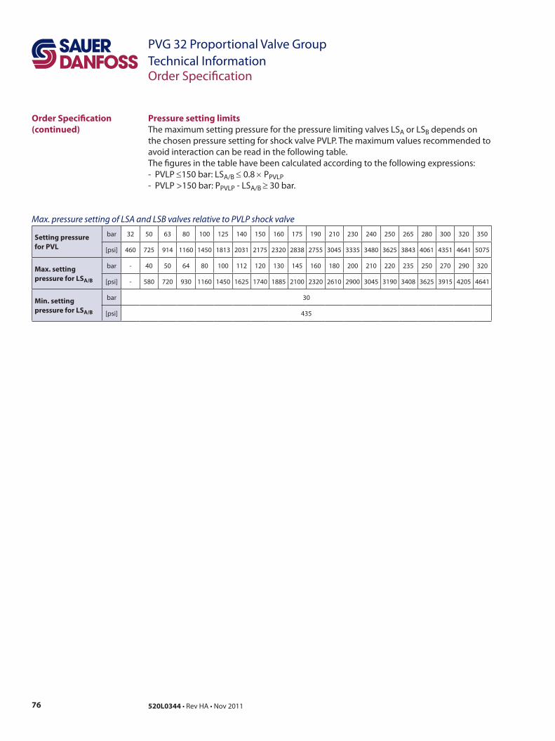
76 520L0344 • Rev HA • Nov 2011
PVG 32 Proportional Valve GroupTechnical Information
Pressure setting limitsThe maximum setting pressure for the pressure limiting valves LSA or LSB depends on the chosen pressure setting for shock valve PVLP. The maximum values recommended to avoid interaction can be read in the following table.The figures in the table have been calculated according to the following expressions:- PVLP ≤150 bar: LSA/B ≤ 0.8 × PPVLP- PVLP >150 bar: PPVLP - LSA/B ≥ 30 bar.
Order Specification
Setting pressure for PVL
bar 32 50 63 80 100 125 140 150 160 175 190 210 230 240 250 265 280 300 320 350
[psi] 460 725 914 1160 1450 1813 2031 2175 2320 2838 2755 3045 3335 3480 3625 3843 4061 4351 4641 5075
Max. setting pressure for LSA/B
bar - 40 50 64 80 100 112 120 130 145 160 180 200 210 220 235 250 270 290 320
[psi] - 580 720 930 1160 1450 1625 1740 1885 2100 2320 2610 2900 3045 3190 3408 3625 3915 4205 4641
Min. setting pressure for LSA/B
bar 30
[psi] 435
Max. pressure setting of LSA and LSB valves relative to PVLP shock valve
Order Specification (continued)
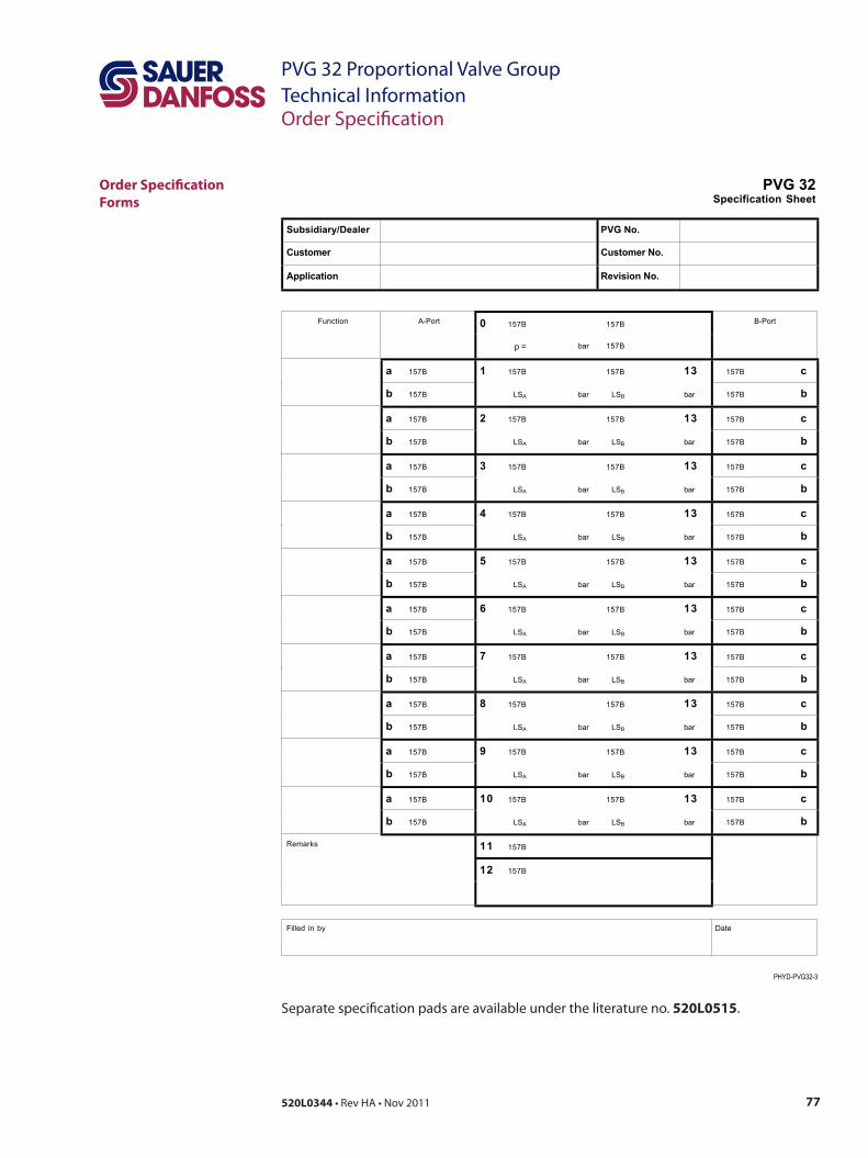
77520L0344 • Rev HA • Nov 2011
PVG 32 Proportional Valve GroupTechnical Information
Separate specification pads are available under the literature no. 520L0515.
Order Specification
Order Specification Forms
PVG 32Specification Sheet
PHYD-PVG32-3
Subsidiary/Dealer PVG No.
Customer Customer No.
Application Revision No.
0 157B 157B Function A-Port
p = bar 157B
B-Port
a 157B 1 157B 157B 13 157B c
b 157B LSA bar LSB bar 157B b
a 157B 2 157B 157B 13 157B c
b 157B LSA bar LSB bar 157B b
a 157B 3 157B 157B 13 157B c
b 157B LSA bar LSB bar 157B b
a 157B 4 157B 157B 13 157B c
b 157B LSA bar LSB bar 157B b
a 157B 5 157B 157B 13 157B c
b 157B LSA bar LSB bar 157B b
a 157B 6 157B 157B 13 157B c
b 157B LSA bar LSB bar 157B b
a 157B 7 157B 157B 13 157B c
b 157B LSA bar LSB bar 157B b
a 157B 8 157B 157B 13 157B c
b 157B LSA bar LSB bar 157B b
a 157B 9 157B 157B 13 157B c
b 157B LSA bar LSB bar 157B b
a 157B 10 157B 157B 13 157B c
b 157B LSA bar LSB bar 157B b
11 157B
12 157B
Remarks
Filled in by
Date

78 520L0344 • Rev HA • Nov 2011
PVG 32 Proportional Valve GroupTechnical InformationOrder Specification
Order Specification Forms (continued)
77520L0344 • Rev GE • Dec 2010
PVG 32 Proportional ValveTechnical InformationOrder Specification
PVG 32SAE Specification Sheet
PHYD-PVG32-3
Subsidiary/Dealer PVG No.
Customer Customer No.
Application Revision No.
0 157B 157B Function A-Port
p = psi 157B
B-Port
a 157B 1 157B 157B 13 157B c
b 157B LSA psi LSB psi 157B b
a 157B 2 157B 157B 13 157B c
b 157B LSA psi LSB psi 157B b
a 157B 3 157B 157B 13 157B c
b 157B LSA psi LSB psi 157B b
a 157B 4 157B 157B 13 157B c
b 157B LSA psi LSB psi 157B b
a 157B 5 157B 157B 13 157B c
b 157B LSA psi LSB psi 157B b
a 157B 6 157B 157B 13 157B c
b 157B LSA psi LSB psi 157B b
a 157B 7 157B 157B 13 157B c
b 157B LSA psi LSB psi 157B b
a 157B 8 157B 157B 13 157B c
b 157B LSA psi LSB psi 157B b
a 157B 9 157B 157B 13 157B c
b 157B LSA psi LSB psi 157B b
a 157B 10 157B 157B 13 157B c
b 157B LSA psi LSB psi 157B b
11 157B
12 157B
Remarks
Filled in by
Date
Order Specification
79520L0344 • Rev HA • Nov 2011
PVG 32 Proportional Valve GroupTechnical InformationNotes
Notes
Local address:
Sauer-Danfoss GmbH & Co. OHGPostfach 2460, D-24531 NeumünsterKrokamp 35, D-24539 Neumünster, GermanyPhone: +49 4321 871 0Fax: +49 4321 871 122
Sauer-Danfoss ApSDK-6430 Nordborg, DenmarkPhone: +45 7488 4444Fax: +45 7488 4400
Sauer-Danfoss is a global manufacturer and supplier of high-quality hydraulic and electronic components. We specialize in providing state-of-the-art technology and solutions that excel in the harsh operating conditions of the mobile o -highway market. Building on our extensive applications expertise, we work closely with our customers to ensure exceptional performance for a broad range of o -highway vehicles.
We help OEMs around the world speed up system development, reduce costs and bring vehicles to market faster. Sauer-Danfoss – Your Strongest Partner in Mobile Hydraulics.
Go to www.sauer-danfoss.com for further product information.
Wherever o -highway vehicles are at work, so is Sauer-Danfoss.
We o er expert worldwide support for our customers, ensuring the best possible solutions for outstanding performance. And with an extensive network of Global Service Partners, we also provide comprehensive global service for all of our components.
Please contact the Sauer-Danfoss representative nearest you.
Products we o er:
• Bent Axis Motors
• Closed Circuit Axial Piston Pumps and Motors
• Displays
• Electrohydraulic Power Steering
• Electrohydraulics
• Hydraulic Power Steering
• Integrated Systems
• Joysticks and Control Handles
• Microcontrollers and Software
• Open Circuit Axial Piston Pumps
• Orbital Motors
• PLUS+1™ GUIDE
• Proportional Valves
• Sensors
• Steering
• Transit Mixer Drives
Members of the Sauer-Danfoss Group:
Comatrolwww.comatrol.com
Schwarzmüller-Inverterwww.schwarzmueller-inverter.com
Turolla www.turollaocg.com
Hydro-Gear www.hydro-gear.com
Sauer-Danfoss-Daikinwww.sauer-danfoss-daikin.com
Sauer-Danfoss (US) Company2800 East 13th StreetAmes, IA 50010, USAPhone: +1 515 239 6000Fax: +1 515 239 6618
Sauer-Danfoss-Daikin LTD.Shin-Osaka TERASAKI 3rd Bldg. 6F1-5-28 Nishimiyahara, Yodogawa-kuOsaka 532-0004, JapanPhone: +81 6 6395 6066Fax: +81 6 6395 8585
w w w . s a u e r - d a n f o s s . c o m520L0344 • Rev HA • Nov 2011