PURPOSE ELECTRONIC TEST EQUIPMENT (GPETE) … · an acute awareness of the criticality of...
131
AD-i33 865 GENERAL PURPOSE ELECTRONIC TEST EQUIPMENT (GPETE) 1/2 AICQUISITION CONSIDERATIONS FOR AUTOMATED CALIBRATION (U) NAVAL POSTGRAlDUAiTE SCHOOL MONTEREY CA W D STAHLER UNCLASSIFIED JUN 83 NPS4-83-82 F,'G 9/2 , N mohhhhhhmmhhil momhhmhhhhhhml Ehhmomhhmhhhl mohhhohEohmhEE smhhhhEEmhhEE smEmhhEEEEEEEE
-
Upload
hoangduong -
Category
Documents
-
view
216 -
download
0
Transcript of PURPOSE ELECTRONIC TEST EQUIPMENT (GPETE) … · an acute awareness of the criticality of...
AD-i33 865 GENERAL PURPOSE ELECTRONIC TEST EQUIPMENT (GPETE) 1/2AICQUISITION CONSIDERATIONS FOR AUTOMATED CALIBRATION(U) NAVAL POSTGRAlDUAiTE SCHOOL MONTEREY CA W D STAHLER
UNCLASSIFIED JUN 83 NPS4-83-82 F,'G 9/2 , N
mohhhhhhmmhhilmomhhmhhhhhhmlEhhmomhhmhhhlmohhhohEohmhEEsmhhhhEEmhhEEsmEmhhEEEEEEEE

1111L1
MICROCOPY RESOLUTION TEST CHARTNATIONAL BUREAU OF STANOARDS-1963-A
,._ -! -- ' ' q .> .:;: .:c: c-- : t- Q'C'CC: <* :.: ,... .; .:'.. ,:~- . .: . - .-

Report Number---- NPS54-83-002
NAVAL POSTGRADUATE SCHOOLMonterey, California
THESISGENERAL PURPOSE ELECTRONIC TEST EQUIPMENT (GPETE)
ACQUISITION CONSIDERATIONS FOR AUTOMATED CALIBRATION
by
William D. Stahler
June 1983
Thesis Advisor: J. W. Creighton
LA- Approved for public release; distribution unlimitedk.-- Prepared for:W. Naval Air Systems Command
Washington, D. C. 20361
,,-.-... ..... . .. .. 83 10 20 0A.

UNCLASSIFIED
REPORT DOCUNTATION PAGE BEFORE COMPLETING FORMnowonT MMGK2. OVT ACSSION NO: 3- 1451INT'S CATALOG NUMBER
I 4LTIT~ (M Raboo)S. TYPE OF REPORT A PERIOD COVERED
General Purpose Electronic Test Equipment (GPETE) Master' s ThesisAcquisition Considerations for Automated June 1983calibration a. PERFORMING ONG. REPORT NUMBER
T. &AJNW*)S. CONTRACT OR GRANT NUMBER(.)
William D. Stahier
9-PR6MNG OAMIZA ION NAN2 AND ADDRESS 0. -PROGRAM ELEMENT. PROJECT. TASKI AREA A WORK UNIT NUMBERS
Naval Postgraduate Schoolmonterey, California 93940
1t. CONTRMOLLING OFFICE MNM AND ADDRESS 12. REPORT DATE
Naval Air Systems Coiiand, Tune 1983Washington, D. C. 20361 Is. NUMBER OF PAGES
M4 ISoITOMIG AGENCT NAME & AODRISW4I 4111ome Swm Cior~Aviu.d Offe. IS. SECURITY CLASS. (of this repat)
U7NCLASSIFIEDISo. OECLASSI PICATION/i DOWNGRADING
SCHEDULE
IS, OIS? UUTION STATEMENT (fo Sie ftepoe)
Approved for public release; distribution unlimited
I?. SU5TSONSTAYEMN (91?O did, 8000 #a No"e It, IiffilaW Mrm Repine
I&. UUPPLEMN4TARY NO9
X611 EGROS (@.UMUSo ai mrve &40of 0900eep modm~10 I block nubot)
automated calibration; calibration; electronic test equipment; generalpurpose electronic test equipment (GPETE)
% S ACT (O M d o M s. sd it MgeODSOM M ageg601t, by block noiII.I)
calibration is a vital logistics element that directly impacts operationalreadiness and mission capability. Declining manpowr resources and fleetexpansion necessitate improvements in calibration productivity. The Navyhas initiated several calibration automation programs. Realization of thefull potential of automated calibration systems requires that the testinstrumient be IEEE-488 general purpose interface bus (GPIB) configured
~ Fen 143 COITION OP INOV "S 1S OOLETN
S/N 0102- 6.,. 014- 6601 JtTASIESECURITY CLASSIOPICATION4 OF THIS PAGE (Ohms 081 nmo
7 .
* general purpose electronic test equipment (GPMT) with GPIB to facilitate
cost-benefit analysis and a discussion of non-quantifiable advantages anddisadvantages, based upon extensive interviews with experts and literatureresea ch. in general, the analysis supports GPIB procurement whenprocurement quantities are large, calibration procedures are lengthy, and/or
* the calibration interval is short
Distibuction! -*raET
AvailFabilitY CodeS IT
S~NOO2.L.O~d66O1UNCLASSIFIED
yFCUmIrv CLAWICATION OF V0418 PAGM(MaSU D td.)

Approved for public release; distribution unlimited.
General Pur pose Electronic Test Equipment (GPE'EE)acquisition considerations for Automated Calibrat16on
by
willia.m D. StablerLieuteriant omma4 der# United States Navy
B.S., Uni.ver.sity ofIllinois, 1971
Submitted in Dart ial fulfillment of therequire.o uts for the degree of
RASTER OF SCIENCE IN MANAGEMENT
from the
NAVAL POSTGRADUATE SCHOOL* June 1983
Author:
Approved by:._Thsis AdIvisor
Second Reader
ar. a Departuen of Administrative Science
Cean of Information an Sciences
3
- - -~~*Z ., ** ... ** . - - .. * .. . . . .
&OSTBACT"A
Calibration is a vital logistics element that diractly
impacts operational readiness and mission capability.Declining manpower resources and fleet expansion necessitateimprovements in calitration productivity. Toward this end
the Navy has initiated several calibration automation
programs. Realizaticn of the full poten.ial of automated
calibraticn systems requires that the test instrumen. be1EE-488 general purpose interface bus (GPIB) configured.This thesis examines the relative costs and benefits of
configuring general purpose electronic test equipment
(GPETE) with GPIB tc faciliate automated calibration. I4.
does so through the development of a simple cost-benefit
analysis and a discussion of not-quantifiable advantages and
disadvantages, based upon extensive interviews with experts
4 and literature research. In general, the analysis supports
GPmD prccuremen t when procurement quantities are large,
calibration procedures are lengthy, and/or the calibration
interval is short.
'4
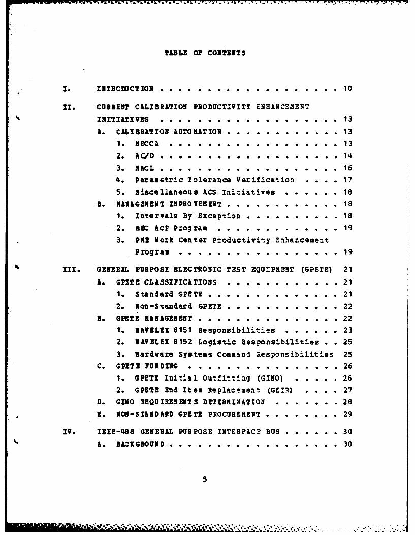
TABLE OF CONTENTS
l. INTRCDUCT ION . . . . . . . . . 10
II. CURRENT CALIBRATION PRODUCTIVITY ENHANCEMENT
INITIATI VES 13
A. CALIBRATION AUTONATION . . . . . . . . . . . . 13
I MECCA . .. . .. . . . . . . . 13
2. AC/D .0. .0.. ... . . 1439 RACL e. . . .a o........ 16
4. Parametric Tolerance Vrification . . . . 17
5. miscellaneous ACS Initiatives . . . . . . 18
B. HANAGEMENT IMPROVEMENT . ... . . . . . . . . 18
1. Intervals By Exception .. . . . . . . . . 18
2. NBC ACP Program . . . . . . . . . . . . . 19
3. PRE Work Center Productivity Enhancement
Program * * . * * ............ 19
III. GENERAL PURPOSE ELECTRONIC TEST EQUIPMENT (GPETE) 21
A. GPETE CLASSIFICATIONS . . . . . . . . . . . . 21
1. Standard GPETE . . . . . . . . . . . . . . 21
2. Non-Standard GPETE . . . . . . . . . . . . 22
B. GPETE MANAGEMENT ... .. ..... ... .221. NAVELIX 8151 Responsibilities . . . . . . 23
2. NAVEL!X 8152 Logistic Respons4bilities . . 25
3. Hardware Systems Command Responsibilities 25
C. GPETE FUNDING . .............. 26
1. GPETS Initial Outfitt ng (GINO) ..... 26
2. GPETE End Item Replacement (GEIR) * . . 27
D. GINO REQUIREMENTS DETERMINYATION .. . .. . 28
E. NON-STANDaRD GPETE PROCUREMENT ... .. . 29
IV. IE!E-488 GENERAL PURPOSE INTERFACE BUS . . . . . . 30
A. BACKGROUND 30
5
-"9'- . -,r :i--lT: l ,*~* '* * .'''* *- ', - .. * *1q"- * *",*"*'."
* *," . .-. ' " ' "
1. Definition . ............... 30
2. History .. . .. . . . . .. .. . . .. 30
B, GPIB SPECIFICATIONS AND LIMITATIONS ..... 32
1. GPIB Functional Subsets . . . . . . . . . 32
2. Codes, Formats and Conventions ...... 34
C. GPIB APPLICABILITY TO GPETE . . . . . . . . . 35
Do GPIB PROCUREMENT POLICIES .......... 36
1. U.S. Air Force Policy . . . . . . . . . . 36
2. U.S. Army Policy . . . . . . . . . . . . . 36
3. Navy Policy . . . . ........... 37
V. GPETE 3PIB COST-BENEFIT ANALYSIS . . . . . . . . . 39
A. CLIBRATICN MANHOUR SAVINGS . . . . . . . . . 40
B. INCREMENTAL COST ELEMENTS . . . . . . . . . . 41
1. Procurement Cost . . . . . . . . . . . . . 412. Incremental Life Cycle Software Costs . . 42
3. Incremental Life Cycle Repair Costs . . . 44
4. Logistics Cost . . . . . . ........ 455. Acceptance Testing Costs . o o . . . . o . 46
C. OTHER COST-BENEFIT ANALYSIS PARAMETERS ANDASSUMPTIONS .o. ... o. . ... . .. .... 47
1. FCA Cost Per Manhour . o . . . . . . . o 472. Discount Rate . . . . . . . . . . .. . 473. Instrument Life Expectancy o . . o . . . . 474. Salvage Value . . . . . . . . . . o . o o 47
5. Number of NECCA Sites o o .. . . . . . . 476. Calibra .on Intervals . . ......... 48
7. Standard Calibration manhours ...... 49
D. COST-BENEFIT ANALYSIS MODEL EXECUTION . . . . 50
E. SENSITIVITY ANLSIS o............ 50F. SON-QUANTIFIABLE ADVANTAGES AND DISADVANTAGES 51
1. Disadavantages . ............. 512. Advantages . . .o o. .. .. 53
G. CONCLUSIONS . .. o . . . . . . . . 56
6
I I , ~l' l , ,-. ,z ,z ,z, .. :,.,...-.-,:,:.. ........ ..... ... ... .. ......... .....

TI. RELATED ISSUES .. . .. . . .. .. .. .. . .. 58
A. GPETE STANDARDIZATION . . . . . . . . . . . . 58
B. GPETE INTEGRATED LOGISTICS SUPPORT ...... 59
C. TRAINING ................... 60
1. On-Site Factory Schools . . . . . . . . . 60
2. Phase Package Training . . .. . e ... 61
3. Sound/Slide and Vidso Cassette Training . 61
4. Manuf acturer Periodicals . . . . . . . . . 61
D. ACS COORDINATION . . . . . . . . . . . . . . . 62
VII. RECOMNENDATIONS ................. 64
A. I3EE-488 SUBSET REQUIREMENTS . . . . . . . . . 64
B. IUEE-488 CODE* SYNTAX AND CONVENTION STANDARDS 64
C. GPETE GPIB PROCUREMENT POLICY. . . . . . . . . 65
C. GPETE FOLLOW-ON PROCUREMENT . . . . . . . . . 65
E. ACS COORDINATION . .............. 67
F. CALIBRATICN/REPAIR TRAINING . . . . . . . . . 67
VIII. EPILOGUE . . . . . . . . . . . . . . . . . . . . . 68
APPENDIX A: DEFINITIONS ................ 69
APPENDIX B: ELECTRONIC TEST EQUIPMENT CLASSIFICATIONS . 74
APPENDIX C: 113-488 FUNCTIONAL SUBSETS ........ 75
APPENDIX D: WAVY IEEE-488 FUNCTIONAL SUBSET REQUIREMENTS 78
APPENDIX E: KATE IE-488 SUBSET REQUIREMENTS . . . . . 79
APPENDIX 1: 3PIB GPETE AVAILABILITY . . . . . . . . . . 80
APPENDIX G: AC/C CONFERENCE ATTENDEES .. . . * ... 81
APPENDIX H: LIFE CYCLE CALIBRATION SAVINGS ANALYSIS . . 83
APPENDIX I: SOFTWARE COST DECISION TREE ........ 85
APPENDIX J: FAILURE RATE DERIVATI3N . . . . . . . . . . 86
7
"m mm* . *' *. -" - ."".-....
APPENDIX K: 1331-488 REPAIR MANHOURS AND MATERIAL COSTS 88
APPENDIX L: GPIB REPAIR CONTRACT COSTS . . . . . . . . . 9
APPENDIX B: LOGISTICS COST FACTOR DERIVATION . . . . . . 92
APPENDIX N: FCl HkNHOUR COST CALCULATION . . . . 95
APPENDIX 0: DISCOUNTING AND THE DISCOUNT FACTOR TABLE . 99
APPENEII P: GPETE LIZE EXPECTANCY .......... 101
APPENDIX Q: CALIBRATION INTERVAL COMPARISON ..... 102
APPENDIX R: STANDARD MANHOUR COMPARISON . . . . . . . 103
APPENDIX S: COST-BENEFIT MODEL SAMPLE EXECUTION . . . 105
APPENDIX T: SENSITIVITY ANALYSIS . . . . . . . . . . . 109
APPENDIX 0: AVAILABILITY REDUCTIONS DUE TC IEEE-488
INSTALLATION . . . . . . . . . . . . . . . 111
APPENDIX v: I333-488 SUBSET REQUIREMENTS FOR AUTOMATED
C.ALIBRATION ............... 116
APPENDIX 9: COfMPARISON OF GPIB SUBSET
REQUIREMENTS/RECOMNEND&TIONS . . . . . . . 117
LIST C IFRENCS . .. .. . . .. .. .. . . .. 119
INITIAL DISTRIBUTION LIST . ....... .... . 124
8

LIST 0F FIGURES
M. ilitary Population Resources . . . . . . . . .12

7-0 P -7 -_ -W!A *J-5 * 7' 0.7 ;- 7 77
1. 0 DUOCIQ
_71Lo__.
The author's assignment as the Avionics/Armament (!1-3)
Division Officer onboard USS JOHN F. KENNEDY (CV-67) brought
an acute awareness of the criticality of electronic calibra-
tion to the mission effectiveness of an aircraft carrier
(CV) and its embarked airwing. Virtually every item of
electronic test equipbent requires callbration. Therefore,
any factor that affects calibration productivity and turna-round time will have a direct effect on both electronic testequipment and electronic system availability.
USS JOHN F. KENNEDY was fortunate to be assigned a
number of highly skilled and highly motivated calibration
technicians. But, in spite of this advantage, calibration
still often created a "bottleneck" in the electronic/
aviotics component repair cycle. Other CVs were not as
fortunate and experienced far greater difficulties.
Improved local management emphasis and planning isrequired to optimize the utilization of available calibra-
tion resources. On USS JOHN P. KENNEDY several competent
avionics technicians were reassigned from other areas to theonbcAcd fleet Calibration Activity (FCA); on-the-jobtraining (OJT) was arranged at local Naval Air ReworkFacility (NeRP) and shore based Aircraft IntermediatemainteDance Departments (AIND); and detailed calibration
planning was introduced. Yet these measures were not
enough. Even in the current favorable (in terms cf techni-cian numbsrs and skill levels) peacetime ervironaent, th. CVFCAs are hard pressed to provide the calibraticn/repairquality and thrcugh~ut rsquired to optimize weapons system
support.
10
, ,- - .- .. . . , ..... . . . . . . . . . . .-. .
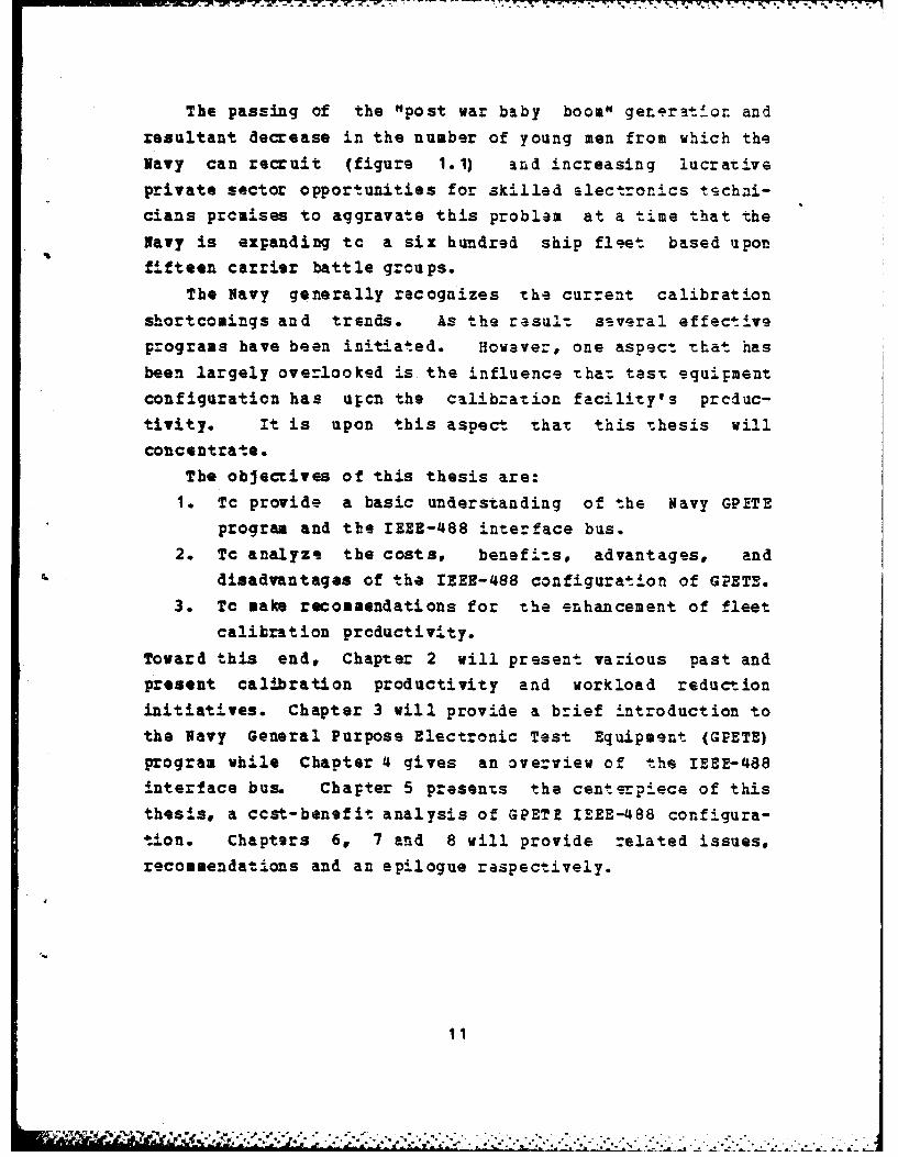
The passing of the "post war baby boom" generatior andresultant decrease in the number of young men from which the
Navy can recruit (figure 1.1) and increasing lucrative
private sector opportunities for skilled slectronics tschni-cians promises to aggravate this problem at a time that the
Navy is expanding to a six hundred ship flget based uponfifteen carrier battle groups.
The Navy generally recognizes the current calibration
shortcomings and trends. As the result szveral effective
programs have been initiated. However, one aspect that has
been largely overlooked is the influence that test equipment
configuration has upcn the calibzation facility's produc-
tivity. It is upon this aspect that this thesis willconcentrate.
The objectives of this thesis are:
1. To provide a basic understanding of the Navy GPETE
program and the IEEE-488 interface bus.2. Tc analyze the costs, benefits, advantages, and
disadvantages of the IZEE-488 configuration of GPET3.3. To make recommendations for the enhancement of fleet
calibration productivity.
Toward this end, Chapter 2 will present various past and
present calibration productivity and workload reduction
initiatives. Chapter 3 will provide a brief introduction tothe Navy General Purpose Electronic Test Equipment (GPETE)
program while Chapter 4 gives an overview of the IEEZ-488
interface bus. Chapter 5 presents the centerpiece of thisthesis, a ccst-benefit analysis of GPETE IEEE-488 configura-
tion. Chapters 6, 7 and 8 will provide related issues,recommendations and an epilogue respectively.
11
* .'mmn....,.;.- .I.*.... .. .. -. ...... ... " . "-".." . .: '' ." ''

- ~ . 4. - .. -+ , - . . .. ,+ -.- - .- .. . .- . . . . ° . " . .
.7'
11.0 U.S. MALES
* __I L I IiI i i i! I I I i '
I I
-0. 17 -21
1.5 15%
a.3 I
z) 9.0-0:| 1.3
S Ounace: IIJGA TP FaS Up (1 601 )1
_ _ _ __- I _ _ _ _ _ _ __i - I ~
__ _
1975 1960 1085 1900 195 2000
Figure 1. 1 Military Population Resources.
This figure demonstrates the decreasing manpower resources
from which the Navy Will be recrulIing over the next two
decades. From a high of 10.8 uilliLn in 1976, the number of
males 17-21 years of age in the populat-,.on of the United
Staues has declined to approximatoly 10.0 mllion i 1983
and is projected to reach a low of 8. million in 1996.
(Ref. 1]
.,
12
,,, . , .- *..-,.-....-'. . . .. . -.. ... .,.--,.,++.. .. . -. . ,,- . ,. .. .
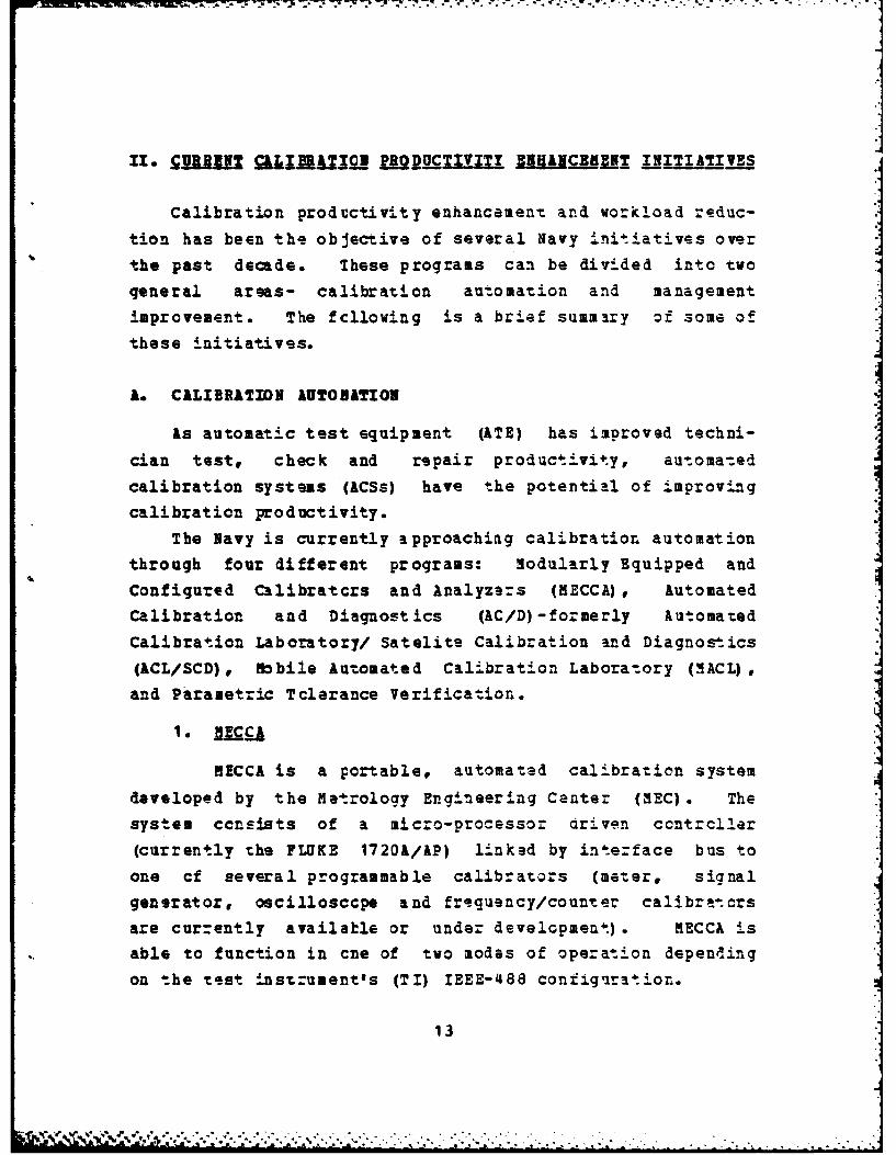
11- !GUIRRfN QJ~JR.UX B2_TIVITY ENHANCE ;K% INITIATIIVES
Calibration prodcctivity enhancement and workload reduc-
tion has been the objective of several Navy init.atives over
the past decade. These programs can be divided into two
general areas- calibration au-omation and management
improvement. The fcllowing is a brief summary of some of
these initiatives.
A. CALIBRATION AUTORATION
As automatic test equipment (ATE) has imoroved techni-
cian test, check and repair productivity, automa-ed
calibration systems (ACSs) have the potential of improvingcalibration productivity.
The Navy is currently approaching calibration automation
through four different programs: Modularly Equipped and
Configured Calibratcrs and Analyzers (MECCA), Automated
Calibration and Diagnost ics (AC/D) - formerly Automated
Calibration Laboratory/ Satelite Calibration and Diagnostics(ACL/SCD), Mobile Automated Calibration Labora-tory (3ACL) ,and Parametric Tolerance Verification.
MECCA is a portable, automated calibration system
developed by the Metrology Engineering Center (MEC). The
system ccnsists of a micro-processor driven ccntrcller
(currently the FLUKE 1720&/AP) linked by intezface bus to
one cf several programmable calibrators (meter, signal
generator, oscillosccpe and frequency/counter calibratorsare cur-ently available or under development). MECCA isable to function in cne of two modes of operation depending
on the test inst ument's (TI) IEEE-488 configuration.
13
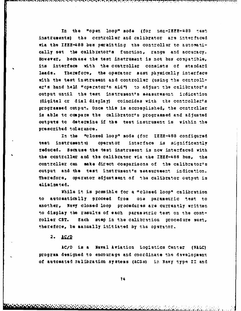
In the "open loop" mode (for non-IBEE-48S testinstruments) the ccntroller and calibrator are intrfacedvia the IZEE-488 bus permitting the controller to automat.-
cally set the calibrator's function, range and accuracy.However, because the test instrument is not bus compatible,
its interface with the controller consists of standardleads. Therefore, the operator must physically interfacewith the test instrument and controller (using the ccntroll-er's hand held "cperator's aid") to adjus-. the calibrator's
output until the test instrument's measurement irdication(digital cr dial display) coincides with the controller's
programmed output. Once this is accomplished, the ccntrclleris able tc compare the calibrator's programmed and adjusted
outputs tc determine if the test instrument is within the
prescribed tolerance.In the "closed loop" mode (for IEEE-488 configured
test instruments) operator interface is significantly
reduced. Because the test instrument is now interfaced withthe ccntrcller and the calibrator via the IREE-488 bus, the
contrcller can make direct comparisons of the calibrator's
output and the test instrument's measurement indication.
Therefore, operator adjustment of the calibrator output is
eliminated.While it is pcssible for a "closed loop" calibration
to automatically proceed from one parametric test to
another, Navy closed loop procedures are currently writtento display the rasults of each paramatric test on the cont-roller CRT. Each step in the calibration procedure must,therefore, be manually initiated by the operator.
AC/D is a Naval Aviation Logistics Center (NALC)
program designed to encourage and coordinate the developmentof automated -alibration systems (ACSs) in Navy type II and
14
type III calibration laboratories. The program is managed
by NIALC Code 330 with contractor support services (CSS)
provided by Science Applications Inc.'s (SAI) Calibration
Support Division. Initially the program only included threecalibration facilities: Naval Air Test Center (NATC)
Patuxent River* NARF Pensacola Type II, and NARF Alameda
Type II.NATC Patuxent River is assignad responsibility for
the development of ACSs. Like MZCCA, th4 AC/D systems arebased cn a wicroprocessor based controller and programmablecalibrators. But unlike MECCA, AC/D procedures are written
to minimize operator intervention. Instead of requiring theoperator to initiate each step, kC/D procedures are, when-
ever possible, "hands off" with the results directlytransmitted to a printer to facilitate review at the opera-tor's convenience. Thus* following set-up and program
initiation, a fully programmable TI could run through theentire calibration procedure without the operator beingpresent. To date NIATC has developed several ACSs includingan AN/APH-4030 radar altimeter test set, ACS that reduces
calibration requirements from forty high skill manhcurs to
8-12 moderate skill manhours (Ref. 2].
AIRF Pensacola is tasked with the development of
systems to detect and diagnose faults in the test instru-ment's IEE-488 bus, interconnecting, and conventional
circuitry and ths instrument's microprocessors. An IEEE-488bus diagncstic system based upon an Interface TechnologiesITC-488 controller has been developed and deploysd to the
type II and III (but not FCA (type IV)) laboratories. Amicroprocessor diagncstic system is near completion and
current planning calls for type II/III deployment in
September 1983. Current plans call for initiating thedevelopment of diagnostics for instrument interconnecting
and ccnvent6onal circuitry in the near fatur.. [Ref. 3]
15
NIBF Alameda is assigned as the AC/D contrcl cPnar
and, as such, tasked with the production and 4istribu-ion ofthe systems developed by the other facilitles.
At the AC/D Ccnfmrence in Dallas, Texas 29-31 March
1983, the remaining NAB? type II and type III laboratcrieswere brcught into the program. The addition of these activ-
ities and their resident expertise (many have independentlydeveloped ACSs) promises to further enhance ACS development
and application.
Because all of the AC/D laborato-ies have FLUKE17201 controllers, many of the AcSs developed under thisprogram will be directly applicable to MECCA.
3. .iAm
The HACL program was initiated in 1981 by NALC under
contract to SAI at HATC Patuxent River. The program'sobjective is the development of a mobile automated calibra-
tion facility that can be rapidly deployed to a forward sitsor used to temporarily augment an existing facility.
NACL is housed in a 9' X 28' trailer that is config-ured with all necessary power, air conditioning, racks andbenches. The installed ACS (called Mobile AutomatedCalibration System (NACS)) is based on a John Fluke 7405Ameter calibrator, modified by the addition of a Tektronixoscillosccpe calibratcr. Unlike MECCA*, whose applications
software and ICPs are stored on floppy diskettes, M ACSstores all its software in a computer for direct access bythe system ccntrcllez.
The HACL program includes aorea than the developmentof HACL calibration capability and logistics. It alsoincludes tasks such as the development of a universal cali-bration procedure generator that will have wide ACS
applicability. [Ref. 4]
16

_ ... ,. , .. . -.- . ., .,o -- - -. ,-. . *, .=- r
. w . , -." -'. .- . . - . .' . - .w" b . ,.V _. a.
Parametric tclerance verification is a caIba-ilon
concept being implemented in the latest generation of Navy
ATE. Instead of individually calibrating ATE building
blocks (BBs) off-line, the station as a whole is certifiedusing a primary reference standard and automated program.
The reference standard may be integrated into the
station as either an imbedded builling block (BB) or as aplug-in interface device (ID). The former configuration
will be isplemented in the AN/USH-470 Automatic Test Station(ITS) and the IN/USH-481 Hybrid rest Station (HTS). The
latter configuration is planned for the AN/USM-469 RADCON
and the AN/USK-429(V)1 CATIIID.Parametric tolerance verification reduces FCA work-
load requirements by reducing the number of station buildingblock (BB) test instruments requiring off-line calibration.
For example, of the 23 AI/USH-470 building blocks, only one
(the calibration module itself) requires off line calibra-
tion. [Ref. 5] Additional advantages of parametric
tolerance verificaticn include:
1. Enhancement of ATE operational readiness by elizi-
nating BE removals at individual calibration
intervals.2. Ckecking of reocte/progranaable features.
3. Testing of instruments in their operational environ-
Ment.
4. Reduction of BE in transit time and damage.
5. Reduction of connector wear by reducing BB removal
requirements.
6. Elimination of the calibration of unused features and
accuracies.
17
4 - . .s.-- -U ,. - -. . . . . . ..,. _
Virtually every Navy civilian manned calibration
facility, whether involved in AC/D or not, has their own
automatic calibratior initiatives and many have scme opera-
tional systems. The author found such programs in force at
Navy Calibration Labcratory (NCL) rustin, NCL Whidby Island,the Naval Avionics Center (Indianapolis), and several NARFcalibraticn laboratories which until recently had not parti-
cipated in AC/D.
B. IAIAGIE IMPROVEMENT
"Intervals By Exception" is a management decision making
approach to calibration interval determination and in-terpre-
taticn developed by EC in 1970. The approach differs frompast model number and serial number interval determination
cri.eria by isolating individual serial * numbers whosestatistical reliability differs markedly from their model's
populaticn norm. The individual deviant instruments (termed"dogs" if significantly less reliable than the norm and"gems" if significantly more reliable) are assigned indivi-
dual calibration intervals (published in the "Metrology
Bulletin" distributed monthly by MEC) . The remaining popu-
lation reliability data is used to determine a model
calibration interval for semi-annual publication in the
"He.rclogy Requirements List" (METRL) , NAVAIR 17-35NTL-1.Isolation of these "exc.ptions11 increases the
modelts calibation interval, thus reducing the total numbercf required calibrations. & test program of 60 "highsubmission" model numbers demonstrated an average interval
increase from 6.8 tc 8.2 months as the result of thisprogram. (Ref. 6]
18
- . -12
2. JZ& ..9.a
In 1976 the metrology Engineering Center changed its
calibration interval criteria from .85 EOP (end of pericd)to .85 kOP (average cver period). The Zesults in terms ofincreased calibration intervals ware dramatic. From June
1976 to July 1979 the average calibration interval of a
sample of 305 GPETE items increased from 8.8 tc 13.6 months.The estimated annual savings resui-ng from this increase
was 18.000 calibrations and 45,000 manhcurs. (Ref. 7] ByOctober 1982 the average interval of these same 305 items
had increased to 15.1 months (Ref. 8].
3. H j~l Q_" ; jjj Productivity Enhancement Program
The Precision Measuring Equipment (PME) Work Center
Productivity Enhancement Program was initiated by the
Aircraft Intermediate Maintenance Support Office (AINSO) in1981. The purpose of this program is to improve the produc-
tivity Cf NAVAIR type IV (ECk) calibration activitiesthrough the identification of depot level (type I, II, andIII calibration laboratories) calibrations that are wizhinthe capability of the forwarding FCA. A survey of ten FCAs
identifisd approximately 25,000 calibration hours in thiscatagory. (Ref. 9]
AIMSO proposes generation of a quarterly or semi-annual re;ort to identify these inappropriate depot level
calibrations. This report, which would be distributed tothe cognizant FCA manager, AIND Office: and type commander,would be used to investigate the causes of -he problem(inadequate screening, training, calibration standa: ds,etc.) so that corrective action could be initiated.
flimination of inappropriate depot level calibra-tions will zeduce test equipment turna-ound time and save anestimated $15 million in NAR? Naval Industrial Funds (NIP)
19
annually. kdditional NIP savings could be realized by
*xtensicn of such a prxogram to NAVSEk and NAVELEX cognizant
activities. [Ref. 103
20

III. fa.T l UUrS.U JUCT. .N. . Z]1sU EQUI. Q(P S
Navy electronic test equipment is generally classifed as
either automatic test equipment (ATE) , calibratio_ st an-dards9 cr electronic test equipment (ETE). ATE consists of
systems of instruments interfaced with a computer (cont-
roller) to work as a unit in perfo-ming -s-. functions.
Calibration standards are thoss instruments which have beer.certified to serve as the accuracy control in the calibra-tion cf other instruments. ETE refers to manuially operated,
stand alone instruments. In recent years, with the intro-duction of microprccessor controlled instruments and
automated calibration systems, these distinctions have
become increasingly clouded.The Navy sub-divides ETE into three general catagories:
general purpose electronic test equipment (GPETE), specialpurpose electronic test equipment (SPETE), and other ETE
(catagory definitions are provided in Appendix B). Of the
three, GPETE contains the greatest number of individual
instruments. In fact, the calibration of GPETE acccunts for
over half of the electronic calibration workload in a CV FCA
(Ref. 9].
A. GPETS CLISSI FCITIOIS
GPETZE is sub-divided into the following two classifica-
tions:
Standard GPETE is equipment which has been deter-
mined by the Naval Electronic Systems Command to mostclosely me-t Navy requirements. This equipment, which
21
_ ' ', ,, *.' . ." ..'..' -.-... . '- . . . . .- '
cousists primrily of off-the-shelf (OTS) comercial testequipment (rE), is listed in MIL-STD-1364 (Navy) aspreferred for procurement- and is approved for service uss.
2. =-SanaZ MT
Non-standard GPETE ire those items of GPETE not
listed in HIL-STD-1364 as prefarred for procurement. This
catagcry includes standard GPETE instrumen.ts whose configu-ration (options) differ f:om the prime configuration listedin MIL-STD-1364 Appendix I.
5. GTI! RANIGUEENT
Prior to the issue of NAVHAT Instruct ion 5430.42 (super-
coded by the NAVHATINST 4790.25 series), on 15 April 1970,GPZTZ management was fragmented among the hardware systemscommands. This instruction assigned Navy-wide GPETE manage-
sent responsibility to NAVELEX. NAVELEX responsibility wasaubsequent y expanded to include overall Test, measuring,
and Diagnostic Equipment (TIDE) management by NAVMAT Notice5430 of 29 3une 1981. This latest change was facilitated by
the transfer of the Test and Monitoritc Systems (TAHS)Office fmcm IATHAT (where it was code 04T) to NAVELEX (where
it is code CST).Vithin HAVELEX GFETE responibilitias are assigne.d tc the
TNDE Division (Code 815) where they are delegated tc twobranches. The Test Equipment ,aintenance Engineering Branch(Code 8152) acts as the test equipment Logistics ElementManager (LEN) and is assigned GPETE responsibilities related
to NAVELEX cognizant prime weapons systems. The Test
Equipment Engineering and Procurement Branch (Ccde 8151) is
responsitle for Navy-wide GP!TE program management (lass
logistics).
22
: ,,-; :,.' :,,:,,, , ..-----.-.-........... .. ...... ... -. -..-

1. JAL Ll ij IEgp.DLUbkLt Ifl
The rest Equipment Engineering and Procurement
Branch is staffed with acquisition engineers and a single
program analyst. It is tasked vith the folloving GPETEmanagement responsibilities:
1. C1. ia=W 2f _j. ETE is classified as GPETE,STETE or other ETE by the Naval Haterial Ccamand's
Electronic Test Equipment Classification Board. ANAVELEK 8151 representative chairs this board andresolves classification through telephone coordina-tion. Only occasionally is a fo-mal meeting
required. [Ref. 11]
2. Oalj i Scecificatons. NAVELEX 8151 carries out
its quality and specification responsibil!ties
through the maintenance of the folloving three stan-dards:
a) HIL-STD-1364, "ilitary Standard for Standard
General Purpose Electronic Test Equipment." Iccnpanion dccument, NIL-SD-1387, provides proce-dures for procurement approval of non-standard
GPETE.
b) NIL-T-28800, "General Specification for TestEquipment fcr Use With Electrical and ElectronicEquipment"
c) NIL-HDBK-265, "Standard General Purpose ElectronicTest Equipment Support Items (GSI)"
Technical support for maintenance of these standardsis provided by the Test Equipment EnvircnentalCompatibility Division (Code 026) at the NavalElectronic Systems Engineerilg Activity (NESEA).
3. if.jZ gr.o rasent g ordinati2a. NAVELEX 8151 is the
liaison betveen the GPETE users/buyers (the hardwaresystem commands) and the GPETE procuring agency
23
. ,, , .- .,',-.. ... •. .. ... . . ... ,- . . . -. .- ,,.. . . . .. ... . .. , . .,,
(SPCC). In this role NAVELEX 8151 is responsiblefor:a) maintenance of an automated data bass that
includes requirements identification, procurementplans and budgeting inputs.
b) Preparation of specifications ("salient character-istics") fcr GPETE procurement.
c) Recommendation of procurement methods.
d) Review, clarification, coordination, technicalapproval, and consolidation of hardware systemsccmmand (SYSCOM) GPETE requirements lists.
[ef. 12]4. G1U ,la_. and j f.udge Ing. NAVELEX 8151 prepazes
GIN Program Objectives 3emorandums (POM) relative to
the GPETE program and the subsequent budget fore-
casts.
5. U.Uj.Azi3&tic. AVELEX 8151 responsibilities for
standardization include:
a) Development and implementation cf a GPETE stand-ardization program which minimizes proliferationand ensures total cost effectiveness without
degrading mission performance.
b) kssarance that standard GPETZ models listed in
MIL-STD-1364 (Navy) ara up to date and minimize
life cycle costs by considering overall reli-
ability, maintainability, repair, calibration and
ILS planning.
c) Control of non-standard GPETE procurement throughmanagement of MIL-STD-1387 procedures.
d) Centralization of procurement to ths maximum
extent possible. [Ref. 13]
24
' ' T%: '$ '"" 'i ' v'' °" , .... ii ,
2. AVELEI 8'152 ltoqs._ R.esponsibilities
In addition to the TMDE management responsibil±-ies
for shore commands (discussed below) NAVELEX 8152 is the
logistics element manage.- (LEM) for GPETE. As such, its
responsibilities include:
1. Development of GPETE ILS.
2. Development of operaticnal logistics support plans
(including repair, calibration, provisioning and
I training) for GPETE.
3. Assignment of source, maintenance and recovrability
(SMSR) codes to GPETE.3. 11ardva;e - nd _ om . Responsibilities
The hardware systems commands (SYSCOMs), as the TMDE
managers fcr weapon systems under their cognizance, are
assigned the following GPETE management furctions:1. Providing NAVELEX with GPETE requirements data,
including the minimum performance specifications, tosupport weapon systems under their cognizance.
2. Consolidation and submission of GPETE initial outfit-ting GINO) requirements.
3. Budgeting and funding identification of cognizantGINO requirements.
4. Development, maintenance and distribution of TMDE
allowace and inventory lists for applicable useractivitie s.
5. Designation of a representative to serve on the
NAVRAT ETE Classification Board. [Ref. 144J
The specific SYSCOM areas of responsibility and
internal GPETE management assignments follow.
25
• - I J ,q,': .,. .. ,, , - .,-,..\,-,. .- -*.* . .,2 . - -- -2 ,- . .. .. .- - . .. . .... .
.1
a. Naval Air Systems Ccmmand
NAVAIR is the TMDE manager for aviatic-n ground
support equipment (GSE). Within NAVAIR, Code 552 (currently
assigned to Code 55223) is responsible for GPETE management,
but most GPETE functions have been delegated to -he Naval
1ir Engineering Center (NAEC) Code 92524 [Ref. 15].
b. Naval Sea Systems Ccmaand
NAVSEA is the TLDE manager for ships and fleet
activities ashore less aviation GSE. GPETE management
within NAVSEA is assigned to the Weapons System Engineering
Division (Code 06C) where it is carried out by NAVSEA Code
06C1C (Suppcrt Equipment Logistics 3anager) . Some GPETE
management functions are performed in house, but all routine
functions have been delegated to Naval Weapons Staticn,
Earle.
c. Naval Electronics Systems Command
NAVELEX 8152 serves as the TMDE manager for
shore activities less fleet activities ashore and aviation
GSE. many of the routine functions have been delegated to
NESEA Code 026, who is assisted by a contractor [Ref. 16].
C. GPITI PUDING
GINO funding is prcvided by the appropriate OPNAV
program spcnsor. NAVSEA and NAVELEX GPETE funding is appro-
priated under Other Procurement, Havy (OPN). NAVAIR GPETE
funding is appropriated under Airzraft Procurement, Navy
(AP N)
26
In the OPN funding arena, GETE funding is "f1.nced"
(cannct be spent on anything else) and is, therefore, not
readily susceptible to reduction. LPN GPETE funding, on the
cther hand, is "unfenced" and, on occasion, has been raduced
to facilitate other kFN requirements. (Ref. 17]
Unlike GINO, GEIR is funded under Operations and
Maintenance, Navy (OMN) and comes directly out of the cper-ating activity's Aviation Fleet aintanance (AFM) or Supply
and Equipage (SSE) funds. henever an item of GPETE is
beyond the repair capability of the custodian, the item is
to be turned into the supply system and a replacement drawn
at the current Navy Stock Fund (NSF) GEIR price (averaging
approximately 4% of the NSF GINO price for a new item)
(Ref. 18].Fleet activities have displayed some reluctance to
use the NSF system. Complaints include high NSF prices,
long replacement lead times, and the marginal quality of the
replacement units (with no warranty). As a rssult, manyactivities have arranged repair at the manufacturer's
service facility and, for a smaller charge, been ensured
quality workmanship, reliability updates, a 90 repair
warranty, a full Navy acceptable calibration, and relatively
rapid turnaround. (Ref. 19]These fle.et complaints are not unfounded. The GPETE
(7Z COG) system availability was only 36.1 during fiscal
year 1982 and 41.i4 during the first half of PY-83
(Ref. 20]. Additionally, while 44% represents an average,
in the past the GEIR price, while always lower than the GiNO
price (which includes a 19.9% surcharge for FY-83), has
occasionally exceeded the GSA Schedule price of a new
instrument [Ref. 21].
27
.* .1 .A!. . * . .- . ,
D. GINO REQUIRREENTS DETERhINATION
GINO requirements consist of both new requiraments and
fleet shortages resulting from past, unfilled initial
outfitting requirements. Program managers of new or updated
weapons systems are responsible, as part of their ILS devel-opment, to identify GPETE requiraments for the support ofthe system. The specific requirements are forwarded to the
system command's GPETE Manager and funding requirements are
passed tc the program sponsor. Because of time constraints
and other factors, not all GINO procurements however, follow
this prescribed procedure. Some items are procured through
other Navy activities (such as Naval Weapons Station, Seal
Beach) with funding provided by the Ship Acquisition Manager
(SHAPE). Others are procured through contractors or ship-
builders. [Ref. 22]Generation of fleet GINO requirements is the responsi-
bility of the type commanders/aircraft controllingcustodians. While NAVHATINST 4790.25 states that this
process should be accomplished through a review of the INRL
(Individual Material Readiness List), SPETERL (Ship's
Portable Electronic/Electrical Test Equipment Requirements
List), or STEAL (Shore Test Equipment Allowance List), this
procedure is actually implemented in a number of ways. For
example, CONNAVAIRLANT and CONNAVAIRPAC require fleet activ-ities to report deficiencies using a "GINO card."
CONSUBFLANT requires the submission of an annual GPZTE
inventory by message and CONSUBLANT identifies deficiencies
du:ing the annual Weapons System Reviews.
Both the program manager and type commander generated
GINO requirements are consolidated by the appropriate SYSCOm
and submitted to NAVELEX 8151. NAVELEX 8151, in turn,reviews and consolidates these requirements and submits
planned requirements to SPCC for procurement.
28
* r " '" " ' " " ' - '' , '" . ' ' -". -' ' '- -" --

.. . . . . . 5. .l * *. ' C - . . -__ " .
. ' o . " "-.. 2' . . ._ .. -- - - ." °
1. SON-STANDARD GPITI PROCUREHENT
henever the items listed in MIL-STD-1364 anr not
capable cf meeting a required need ani that need can be met
ty a non-standard item, a request/justification for non-
standard GPETE is sutmitted in accordance with MtL-STD-1387,
"Procedures for Submission of Application for Approval of
Non-Standard Gereral Purpose Electronic Test Equipment
(GPETE)."
The request is submitted through the cognizant SYSCCM to
NESEA Code 026 where review is accomplished by a cent-actor.
The reviever recommends approval or disapproval (a recommqn-
darion for disapproval is always preceded by discussion withthe originator). NESEA Code 026 reviews the recommendation
prior tc fcrwarding the request to the originator with a
copy to UAVELEX 8151. (Ref. 23]If approved and funded, the non-standard GPETE require-
ment is consolidated with other GPETE requirements for
procurement by SPCC cr is purchased directly with authoriza-
tion from NAVELEX 8151.
29
IV. .. e-.2r. r. u-ia . w., r-. c ... c- a
A. BACKGBOUND
The ANSI/IEi-488-1978 is an AmerIcan National
Standard digital interface for programmable instruaentation.The standard specifies electrical, mechanical and fu c-icia!characteristics for the purpose of:
1. defining a general purpose system for limiteddistance applications (twenty meters or lass),
2. enabling the interconnection of independently manu-factured instruments into a s-ingle functional system,
3. permitting instruments of a wide range of capability
tc be simultaneously interconnected into a system,
4. permitting direct =onsunication between instruments,5. defining a system with minimum restrictions on the
perfcraance characteristics of the instrumentsconnected within the system,
6. defining a system that permits asynchronous coamuni-caticns over a wide range of data rates,
7. permitting the design of low cost systems composed oflow cost instruments, and
8. defining a system that is easy to use. [Ref. 24]Or simply, the standard provides a szandard interface for
instrument interconsunication, thereby permitting inst.ru-ments to te easily integrated into an autoaat.d system.
2. jstor
Because 3f the increasing complexity of electronic
equipment and a scarcity of electonics engineers and tech-
nicians during the past two decades, the electronics
30
industry fcund an increasing need to automate rou-tine
measurement tasks.
Early implementation of automated systems was bcth
complicated and expensive. The lack of an interface stan-dard resulted in each system being austo2 built. Interfacedesigns were so individually tailored to a specific applica-
tion, that even the addition of one instrument to a system
could require major reengineering. As the result, these
early systems were very expensive and automation was
restricted to very high volume testing or to applications inwhich tke system cost was low compared to the value of the
test results.
During the late 1960s and early 1970s, the necessityof a industry standard interface became increasingly appa-
rent and several electronic equipment manufacturers
initiated research and development efforts in this area. Ofthese, Hewlett-Packard was the clear leader. Internationalinteresta in the establishment of a suitable interface stan-dard was also developing at this time, particularly amongGerman electenics organizations.
In mid-1972 Hewlett-Packard began participating withvarious national and international standards bodies in thedevelopment of an interface standard. The United StatesAdviscry Ccmittee, composed of both users and manufac-turers, adapted the interface concept developed byHewlett-Packard (called the Hewlett-Packard Interface Bus or
HP-ID) as a starting point. The subsequent draft of anP-ID based proposed standard was evaluated by the Committee
and submitted to the International 3lectrotechnicalCommittee (IEC) in the fall of 1972 as the United State'sproposal for an international interface standard.
In September 1974 the IEC approved the UnitedStates' proposal with minor modifications for formal ballot.The proposal was subsequently approved and published as IECStandard 625 in 1977.
31
......
In the seanwhile, the IEEE Technical Coumi-tts on
Automated Instrumentation approved a d-aft document of aHP-1B based interface standard in the fall of 1974. The !ESE
Standards Bcard approved the draft in Decamb-r 1974 and
publisbed it as IEEE Standard 488-1975 in April 1975. InOctober 1975 the same standard was approved by the American
National Standards Institute (ANSI) and published as ANSIStandard 1C1.1-1975. (Ref. 25]
The IEC and ANSI/IEEE standards are nearly id-.nticaland totally compatible with one exception-the ccnnector.
The IEEE standard (new generally referred to as the GeneralPurpose Interface Bus, GPIB) employs a 24 self-wiping
contact ccnnector. The IEC standard specifies a 25 pinconnector (using one additional ground) identical tc theRS-232-C connector (therefore, presenting the possibility ofequipment damage through the interconnection of th-se two
incompatible buses). The interconnection of instrumentsimplementing the two different connectors is easily accom-plished using a IEC/IEZE adapter. (Ref. 24]
Since 1975 beth the IZC and ANSI/IEEE standards hav.undergone a number of minor changes. The current standardis designated IEEE Standard 488-1978 and IEC Standard 625-1.
3. GPIB SPR ?C!cATICES AND LIBITATIONS
The IE E-Standarl 488 specifies ten functions that agiven instrument's interface may implement. All of thetg
functions are optional. The extent to which a given func-tion is isplementsd in an instrument is speclfid byfunctional subset designations (refer to Appendix C for acomplete list of functions and subsets). Care is required
in selecting GPIB configured instruments. "Iany instruments
are labeled "488 Copatible" or '"GPI3 Compatible#" but in
32
,- * ...... . . .
the extreme the label nay only mean that the instrumqnt has
a standard connector." (Ref. 26]
GPIB equipaent selection is made even more lifficultbecause of the general lack of information supplied by manu-
facturer's catalogs and, in many cases, even by the
applicable maintenance manuals. rhe 1983 versions of theHevlett-Packard, Tektronix and John Fluke catalogs generally
do not specify the IZEE-488 functional subsets irplemented
in a particular instrument. At most, the :aanufactureriscatalogs may specify that an instrument is "talk only,""listen cnly," or "fully programmable." [Ref. 25,27,281
Even the term "fully programable" can be deceptive.
Although all functicnal subsets may be implemented in the
"fully programmable" instrument, all the subsets may nct beimplemented for all cf the front panel function and range
controls. Thus, some front panel controls may be remotely
operated (via the bus) while others require local (front
panel) operation. (Ref. 29]GPIB configured equipment selection is, therefore,
not a straight forward process. It requires both a know-
ledge of the functicnal subsets required for a particularapplication and a determination of the functional subsets
implemented by the instruments under consideration.
Navy interface requirements are specified by
MIL-T-28800, paragraph 3.13.2. This specification statesthat all logic interfaces in electonic test equipmet. should
be in accordance with IEEE-STD 488-1978 and goes on tospecify the required functional subsets (ref.r to ppe.ndixD). The United States Air Force Modular Automated Test
Equipment (HRATE) functional subset requirements a.e provided
in Appendix E. Additional discussion of this topic takes
place in Chapter 7.
33
.| . - . . ' .
IEEE Standard 488 specifies the hardware irte-fice,basic function protoccl and a set 3f interface messages to
control the interface functions. However, the standard dcesnot specify the syntax or coding of device-dependent
messages-the messages that control the programmable features
cf the instruaent. [Ref. 30]Therefore, while the hardware is specified, the
lanuguag . of communication is not. "I: is much like a tele-phone system-the hardware link is well defined, but unlessboth parties speak the same language, communication is
impossible." (Ref. 27]In spite of the lack of code, syntax and convention
standardization, many compatibility problems have beenavoided by the adherence of most alectronic equipment manu-facturers to the following two related standards:
(Q1 . ASCII is used in most GPIB instruments for
bus data transmission.2. J _ P This standard format specifies three
types of numbers (integers, r-eals, and reals with
exponents) and transmission of the most significant
digit first.
Adherence tc these standards is requi-ed in the procurementof lavy elect-onic test equipment as specified in
NIL-T-28800, paragraph 3.13.2.3:
ess otherwise required in the detae;ed specificatcn,all numeric and alpha-r.americ data (input' and outftit)shall be american Standard Code for InformationInterchange (kSCII) and the most significant digit shallbe transferred f -at.
34

while two major potential sources of incompatibili-y
have been eliminated by manufacturer adherence tc related
standards and by military specification, other sou-css ofincompatibility have not yet been addressed. Some of these
are:
1. Method of starting a message.
2. Methcd of terminating a message.
3. Convention to prevent execution of any part of a
message until the entire message is ro.ceived.
Some manufacturers have attempted -:o devqlop standards for
these other sources of incompatibility. Tekrcnix's "Codes
and Formats" standard represents one widely accepted
approach (lef. 31].
The Air Force's Proposed Standard 2806564 Rev D of
05 May 1982 delineates various syntax and coding require-
ments (Continuous Integrated Intermediate Language (CIIL))
for HATE qualified systems. CIIL has been submitted as IEEEProposal 981 for inclusion in the IEEE-STD 488 [Ref. 32].
Pending addition of thorough codes, formats and
conventions specification to the IEEE-STD 488, the selector
of GPIB test equipment must ensure that procurement specifi-
cations require codes, syntax and conventions compatibilitywith the other GPIB instrumentation.
C. GVIB APPLICABILITY TO GPETE
Unlike the Air Fcrce, which through its SATE program is
attempting to make general purpose TMDE (i.e. GPETE) compa-
tible tc ATE applications, the Navy's ATE efforts areconcentrated on development of a common ATE station for all
applications. Vith a fey exceptions, neither the cur~ent
"family of ATE" (seven different ATE statins) or the
Consolidated Systems Support (CSS) program (now entering
full scale development) rely on the use of GPETE as ATE
uildirg blccks.
35
V M r.W.

Therefore, the iajor applicat-ion of GPIB in GPETE would
be to facilitate autcmated calibration and, specifically, to
facilitate the closed loop calibration of the ins-rument
using the MECCA system.
The current number of GPETE items availabla with GPIB is
small. A comparison of the MIL-SID-1364F and the 1983
versicns of the Hewlett-Packard, John Fluke, Tektronix and
Ueinschel catalogs only identified one item with GPIB stan-
dard and seven others in which the 3PIB option was available
(refer tc Appendix F). Although the number of items is
currently small, it is increasing rapidly because of market
demand and the simplicity of implementation resulting from
the introduction of standard GPIB integrated circuits.
D. GIB PBOUR3NRUIT POLICIES
The United States Air Force purchases TMDE withIBEE-488 whenever it is available. This policy, which has
been in effect since 1981, reflects verbal vice written
dirsctien and was implemented primarily to facilitate auto-
mated calibration. The Air Force has even been successfulin securing agreements with manufacturers to provide GPIB in
instruments wken the cption is not commercially available
(e.g. Tektronix 465 oscillcscope). [Ref. 33]
2. g. tgj=
The United States Army loes not have a written
policy for the procurement of IEEE-488 with its TMDE. In
spite of se pressure from the Army's Development andReadiness Command (CARCOM) to devise such a policy, theindividuals involved in TtNDE procurement at the
Communications and Electonics Ccmmand (CECOM) have avoided
formulation of such a policy. These individuals prefer the
36
S. .
current situation because it permits a case-by-case evaiua-
tion and avoids the requirement to justify any policy dsvia-
tions. The Army currently has few automatic test equipment
(ATE) applications, but has introduced various automaticcalibration systems. (Ref. 3J]
3. JAZ Pclicl
Currently the Navy does not have a specific GPETEGPIB procurement policy. To fully understand the currentsitlaticr., the positicns of each of the principals involve4
will be presented.
a. N&VELEX 8151 Position
NAVELEX 8151's position is summarized as
follows:
1. No specific GPIB procurement policy currently exists.However, the fcrmulation of such a policy is under
study.
2. Ultimate responsibility for initiation of GPIB GPETE
requirements rests with the users, i.e. the hardwaresystems commands.
3. Currently, requests for GPIB configuration of GPETEshould be generated through normal MIL-STD-1387
(requests for non-standard GPETE) channels. However,
generation of the specific policy shculd eliminate
this requirement.
4. Receipt of HIL-STD-1387 requests fcr GPIB configuredGPETE will result in a review oO the MIL-STD-1364
characteristics to ascertain if GPIB should be made
standard. (Ref. 35]
37

b. NAVELEX 8152 Position
NAVELEX 8152, as the TSDE manager for shcre
commands, holds the fcllowing position:
1. Any GPETE GPIB policy should be generated by NAVELEX
8151.
2. All GPETE should be procured with the bus when avai-
lable. To make this point NAVELEX 8152 directed the
NESEA contractor who consolidates shore establishment
GP!TE requirements to universally specify GPIB, where
appropriate, on all future GPETE requirement lists.
(Ref. 36]
c. NAVAIR 552 Position
Although NAVNIR 552 requires GPIB for most AT'S
applications, it has no specific policy regarding GPIB
configu:aticn of GPETE. Following the author's 22 February
1983 visit, NAVAIR 55223 tasked NAEC 92524 to coordinate
with IAVSTA and NAVELEX in the formulation of such a policy.
(Ref. 37]
d. nAVSEA 06C1C Position
The position of NAVSEA 06C1C regarding the GPETE
GPIB Frocurement can be summarized as follows:
1. Prefers no definitive policy so that case-by-case
decisions can be mads.
2. Generally not enthusiastic about GPIB procurement
because of the unlikelihood of GPETE ever being used
in an automated test system. However, the special
purpcse application of GPETS as ATE building blocks
is recognized.
3. The mcney spent on GPIB procurement can often better
be utilized by procurement of other, more useful
GPETE options. (Ref. 38]
38
V. M21 GRIS !9OS2TBjEIZ ANALYSIS
One of the contributing factors to the absence cf a
definitive GPIB GPETE procurement pol-icy is the lack of ananalysis which weighs relative costs, be nef-Ii ts, advantages
and disadvantages of GPIB configured GPETE. This chapterwill attempt to rectify that situation through the develop-ment cf a simple cost-benefit analysis model for GPIB GPET!"
confi guraticn.
The model attempts to quantify all GPIB costs and disad-vantages and has succeeded in all but two relativelyinsignificant cases, on the other hand, the only ccstadvantage quantified is the resultant calibration manhoursavings. All other advantages are presented as non-
quanti fiables.Because of the greater degree of quantification achieved
for costs and disadvantages compared to benefits and advan-tages and, because of the critical positions taken inderivation cf the various cost alements, the model is a verycritical analysis. This analysis is not, however, consid-ered to be a "worst ossible case" (a fo-tiiori) analyss.
The model is based upon the ife cycle cost of a singleitem f GPETE, not upon the entire instrument population.Its application, therefore, relies upon an assessment of the
number of ±.nstrumente expected to be procured.Although quantifiable data was used where it was avai-
lable, the scarcity of such data lead to a heavy relioanceupon expert opinion. Because of its complexity and demandsupon the experts" time, a Delphi technique was not used.instead, various experts were surveyed via telephone conver-sations, uestionnaires and visits. The results of hesesurveys and the model's parameters were then discussed and a
39
lable,. . scarcity fsuhat l.........ea.y......n_
iI upom expert opinion........0. Beas fi opeiy n.ead
general concensus achieved during a presentation at the AC/D
Conference in Dallas, Texas on 30 March 1983 (refer to
Appendix G for a list of attendees). A discussion uf -he
elements of the model follows.
A. CALIBRATION MANHOUR SAVINGS
Many claims have been made about the magnitude of the
manhour reductions that can be achieved through autcmated
calibraticn. Based upon comparisons made during an intro-
ductory tcur of MECCA through a number of Navy calibration
activities, MEC's prcmotional film "MECCA" claims that MECCA
produces calibration manhour reductions [Ref. 39]. Jchn
Fluke Corporation claims that their 7405A Automatic Meter
Calibraticn System (like MECCA based upon a FLUKE 1720A
controller and 5102 meter calibrator) reduces manhours by "a
factor of two to three" [Ref. 40]. Yet, in spite of these
claims, discussions with numerous Navy calibration tachni-
clans indicate that MECCA open loop meter calibration is
often slcwe- than manual calibration.
The calibration techniques often used in the fleet
provide the source cf this disparity. Experienced techni-
cians often by-pass some calibration staps and "piggy back"
meters (calibrate more than one meter at a time), unauthor-
ized methods aot feasible with MECCA. SEC's primary reason
for developing MECCA was not manhour savings, but rather
improved procedural ccmpliance. Based upon fleet comments
MECCA is achieving this objective.
But the apparent failure of MECCA to reduce meter cali-
bration manhours does not refute its potert:al. Fleet
comparisons are of "apples and oranaes"-complete versusincomplete procedures. Fu.tharmore, these comparisons are
based only upon open loop meter calibrations.
40
A survey of experts, limited quantified data and -theAC/D Conference discussion resulted in agreement on a 30%manhcur reduction factor for MECCA closed loop compared toMECCA open loop calibration (Appendix H provides a more
detai'led derivation)This reduction is substantial, but not nearly what could
be achieved if MECCA closed loop procedures were written to
minimize operator intervention by only stopping the program
to display test results for failures. mEC agreed with this
assessment and plans to invest-igate changing the procedures
accordingly [Ref. 41]. The impact of such a change was
discussed at the AC/D Conference and a 50% reducticn factor
agreed tc if the instrument calibration procedures (ICPs)are changed.
Even further reductions are possible in a high vclume
calibration facility. In this environment, with sufficientthroughput and multiple MECCA stations, a single cperatorusing minimum intervention ICPs could simultaneously carry
out two or more calibrations.
B. IUCREIRUTAL COST ELERENTS
1. Frocuremenj Cost
The procurement cost is the incremental cost of
inclusicn of the IEEE-488 option in an item of GPETE.
Although manufacturer's catalogs clearly specify this cost,
the catalcg cost represents a single unit retail price.Since the Navy purchases GPETE competitively and in quan-tity, its costs are far below retail.
In this life cycle cost model, the procurement costis an output. The model will consider all other quantifi-
able costs and benefits and produce a figure that representsthe maximum price that the Navy could pay for the GPIB
option and still "break even" over the instrument's life
I.41
N
cycle. Comparison cf this resultant cost to the known or
anticipated incremental cost of the GPIB configuration will
assist in the decisicn making process.
2. LUSA4 Ife! 9cZle Software- costs
MECCA software consists of two differentelements-the applications software (or "handler") and theinstrument calibration procedure (IC2). The applications
software is applicable to an entire class of test equipment.Currently MECCA application software is available or isunder development for meter, enhanced meter, oscilloscope,
signal generator and counter/frequency calibration. Becauseapplication software is not unique for a given instrument
and wculd be developed regardless of any GPIB procurementdecisicn, all related development, distribution and mainte-nance costs are "sunk" and non-incremental. Thus,
application software costs are not considered in thisanalysis.
ICP software costs, on the other hand, may be either
incremental or non-incremental. If the GPIB procurementdecision results in the development of an additional ICP,the ICP software costs are incremental. Otherwise, ICPsoftware costs are ncn-incremental and should not be consid-
ered. To aid in deciding if the ICP software costs shouldbe considered in the cost-benefit model, a decision tree is
provided in Appendix I.There is a remote possibility that an applicable IC?
already exists for the GPIB configured instrument, but noapplicable ICP exists for the non-GPIB instrument. In sucha cast the incremental software costs become a credit forthe procurement decision.
It is recognized that the decision maker willprobably not have ready access to the information needed tomake such a determination. However, MEC, as the control
42
center fcr all ICPs, shoull be able to provide the nec.ssary
information.
a. Software Development Costs
HEC is currently paying ccntractors $2,500 to
develop a MECCA ICP (cost includes a paper conventional
manual ICP) regardless of its simplicity or complexity
[Ref. 42]. Each ICP may be applicable to as many as ten
instruments, but because this analysis only considers cases
in which development cf a new ICP is required, all develop-
ment costs will be apportioned to the first instrument.
Software development costs will be "sunk" for future inst.ru-nents that are able to use the ICP. Therefore, the softwaredevelopzent cost per unit is calculated by dividing $2500 bythe expected number of instruments to be p-ocured.
b. Software Distribution Costs
NEC estimates that it costs $5 to produce and
distribute a single ICP diskette (Includes $2.80 for the
blank diskette) [Ref. 43]. Although as many as ten ICPs can
be placed on a given diskette, NEC is currently limitingthis number to five (all meter ICP diskettes have five ICPs)(Ref. 44]. The initial issue quantity of the diskettes is
one per site, but this analysis will assume that each site
will requisition a second set of diskettes as a reserv.. Itis further assumed that each diskett . will be replaced
semi-annually as the result of ICP caanges, damage and/or
loss.Distribution of ICP software for newly developed
ICPs will, therefore, cost $4.00 ((35/disk X 2 disks/
distribution x 2 distributions/year)/ (5 ICPs/disk)) per
instrument model per site per year. Apportionment of theICP distribution costs to the individual instruments is
calculated by multiplying $4 by the number of IECCA sites
43
and dividing the result by the number of instruments to be
procurad.
c. Software Maintenance Costs
As the result of ICP errors, procedure updates
and hardware changes, continued ICP software engineering isrequired after initial development. This cost element isvery difficult to anticipate because some ICPs may never
require change, while others are changed numerous times. Adiscussion of this subject at the 29-31 dfarCh 1983 AC/DConference lead to a general concensus that the life cycle
cost cf ICE maintenance would at least equal the initialdevelopment cost ($2,500). To alloca-te this cost over thelife cycle of the instrument, this analysis will assume thatthis cost will be $300 per year for each of the first 9years of the instrument's life expectancy. Apportioningthis cost to an individual instruaent will again -equire
division by the expected instrument population.
3. eaakiai L glcle Repai Costs
Inclusion of the tEEE-488 bus in an item of GPET!
introduces a degree cf complaxity to the instrument and is,therefore, likely to increase the instrument's life cycle
repair costs. Calculation of life cycle repair costsinvolves the determination of two factors: the failure rate(reliability) and the average cost of a repair
(maintainability).
a. GPIB Failure Rate
The Navy has experienced a GPIB rejection rateof approximately 30% during the ac:eptance tssting of cali-
bration standards [Ref. 45]. These rejections seldomrepresented GPIB malfunctions. Rather they almost univer-
sally xepresent*ed non-standard GPIB implementaticn by the
'44
manufacturer. Navy calibration standards GPIB acceP ance
tests are conducted using the Interface Technology ITC-488bus tester and a Navy developed software (EPRO) program.
In most cases of acceptance test failure, the manufacturerhas willingly made the required modifications (usually onlyinvolving reprogramming of the instruments' GPIB EPROM soft-ware). Additionally, the occurance of such problems has
been significantly reduced since the introduction cf stan-
dard IEZE-488 integrated circuits. [Ref. 46]After passing initial acceptance inspections,
the IEEE-488 bus has proven to be extramely zaliable. This
analysis will use a 2% failure rite (a 2% chance of GPIBfailure at each calibration induction). Derivation of -thisfigure is provided in Appendix J.
b. Repair Hanhours and Material Costs
For purtcses of this analysis the averageIEZE-488 repair action will require 3 manhours and $40 ofmaterials. Because of the limatad GPIB repair expertisecurrently in the fleet, the MARF LOE hourly rate of $48 willbe used instead of the $28 FCA hourly rate. Derivation of
the repair labor and material =eqairsments is provided in
Appendix K.
Int:oduction of an additional ISEE-488 instrument
into the inventory will result in increased logistics costs
because Cf the need for additional parts support . parts
cataloging and holding costs. In the pas- IEBE-488 bus
implementation was accomplished in a unique manner by virtu-
ally every manufacturer, often differing among instrumentsfrom the same manufacturer. Today implementation is
becoming more standard, because of the introduction cf thestandard IEEE-488 integrated circuits (such as the Texas
45
Instrument's 9914A). Because of standardization, the ir.c:-mental lcgistics ccsts of introducing anothtr 1E77- 488configured instrument will not be significant. I: -thisanalysis, incremental logistics costs will be assumed -oequal forty percent of the total life cycle repair materialcosts. Refer to Appendix K for the derivatiCo cf thisfigure.
Traditionally, GPETE product testing has ccnsisted
of bid sample testing and the subsequent accepta.ice of the
anufaCtirer's test results. In spite of the high GPIBrejecticn rate during calibration standa-ds acceptance
tasting, the traditional GPETE test methodology will sufficefor GPIB configured GPETE.
As explained earlier, the high calibration standardsGPIB rejection rate was the result of non-standard GPIBimplementation, not GPIB malfunctions. Therefore, theobjective cf any GPIB GPETR testing program would be toensure that the instrument conforms with -the Navy's ITC-488test parameters before contract award. In other words, thebid sample testing should include this GPIB test.
Subsequent testing (and reporting) of sample items by themanufacturer using the ITC-488 would be made part of the
contract.
The incremental cost of this additional test will be
small and, since specified in the IFB (and contract), wouldbe part of the incremental GPI3 procuremant cost. For these
reasons, additional GPIB testing costs will not be consid-ered as a separate element in this analysis.
46
C. OTHER COST-BNErIT ANALYSIS PARAMETERS AND ASSOMPTICNS
In this analysis an FCA hourly rate of $28 will be
used. Derivation is provided in Appendix N.
2. 2,_ oulAt
In accordance with DOD Directive 7041.3 and OMB
Circular A-94, a ten percent (average factor) discount -ate
ill be used in this analysis. P'n explanation of
discounting and a table of discount factors is provided in
Appendix C.
3. .La"jtJj eLI~ac
A generic list of instrument life expectancies is
provided in Appendix P.
4. flivage Lj13
This analysis will assume that the incremental
salvage value a GPIB equipped test instrument 'Is
negligible.
5. 1JUj 2.:r U~_ j_:ies
The number of 3ECCk sites is required to calculate
software distribution costs. Because five ICPs reside on
each diskette and as many as ten instruments may use the
same ICP, it wculd be nearly impossible to calculate the
exact number of MECCA sites to which a given diskette may be
distributed. It will, therefore, be assumed that every
diskette will be distributed to each MECCA site. The number
of RECCA sites is equal the number of FLUKE 1720A and
1720A/AP custodians (93 as of 20 March 1983) [Ref. 471 and,
therefore, can be obtained from The Weapons Quality
Engineering Center (Code 373) , Naval Weapons Station,
Concczd.
47

If current COMSURPLANT plans to place MECCA on
virtually every combatant in the Atlantic Fleet are imple-
mented, the number cf sites will increase to approximately
250. Expansion of such a plan to the Pacific Fleet would
further increase the number of MECCA sites to approximately400.
6. "a .br.t. io._.n j_I.Zv,,1
The length of the ins-trument's calibration interval
is required to facilitate the calculation of the number and
timing cf calibraticns (including a calibration prior toinitial use) during the instrument's life cycle. Any one of
the fcllcwing means for this determination may be used:
1. nHG= Taln rument in inventoI.. In caseswhere a non-GPIB parent instrument already exists inthe inventory, the calibration interval may be fcund
in Section 3 of the "M1etrology Requirements List(BETEL0" NkVAIR 17-35MTL-1.
2. Ion-GPfI j~jn ;2_sjument No T~ Tle Tzetv I nthe case that a non-GPIB parent instrument does not
exist in the inventory the following calibrationcycles may be used:a) faMI& urer's C_1bratjn Cycl*je. Manufacturerfs
calibration intervals tend to be shorter than the
corresponding METRL calib-ation interval. A
sample of twenty instruments (five from each MECCAapplicable generic group) yielded a manufacturer'saverage interval of 7.8 months compared to theIETRL average of 12.9 months (see Appendix Q forthe sample elements). Therefor., use of the. manu-facturer's calibration interval may result in anunrealistically high calibration lif-e cycle cost
savings.
48
ts
7 7 7 7. -7 7' 7-7 -. .7 -:- 7. 77- . 777 -q
b) qETR Gte=r QL_.ra r Cyle Because the
M1TRL generic calibration interval (found inSection 2) is a very conservative estimate, use of
this figure will result in a unrealistically large"'number of life cycle calibrations and will, there-
fore, lead to an overly optim-stic calibration
manhour savings figure. Appendix Q provides accmparison cf generic caliDration intervals with
both the METRL model number interval and the manu-facturer's recommended interval.
Other more complex schemes a.e also possible. Many new
instruments are initially placed on the generic calibrationinterval and subsequently changed as sufficient MEASURE data
is accumulated (increasing 90% of the time) [Ref. 48]. Ascheme using this approach would result in a graduallyincreasing calibration cycle.
"7. =a.j..d Q_.a,1=:t-ion_ Ma.n.Jo s
This analysis wiII assume that the manhours required
to perform a MECCA open loop calibration is equal to thestandard manhour/calibration figures available from MEASURE.This assumption is tantamount to equating MECCA open loopand conventional manual manhour requirements. Based uponfleet input cn the relative speed of MECCA open loop meater
calibration, this assumption may be conservative.Like the calibration interval, calibration standard
manhours can be determined in several ways.
I. =jjL-M Pu.j luueIJ Invento;. If the
non-GPIB parent inst-ument exists in the inventory,the standard calibration manhours may be derived from
any of a number of MEASURE report formats. The dataused in the sample model execution (Appendix S) wastaken from FRANS format R-1.
49
. . . . ,
2. _M.Uufajj~j ltSnd&;_o This rate can be derived by
dividing the manufacturer's standard calibration fee
by his current hourly rate (provided at the end ofAppendix i). Caution, however, is advised in the use
of this figure. Manufacture: service cen-ers aregenerally better equipped and staffed tha. FCAs.
Therefore, they generally complete calibra-tions in
significantly less time than can be achieved in the
fleet. A sample of 20 instrument-s (five from each
L ECCA applicale generic group) showed no discernible
relationship between the manufacturer's and MEASURE
manhours. In six cases the MEASURE standard was
lover than the manufacturer's. In the other fourteen
cases reverse was true. Overall, the MEASURE stan-
dards were slightly higher (3.5 hours compared to 3.1
hours) than the manufacturer standards. Refer toAppendix B for the sample data.
D. COST-BzINrI? AIALISIS MODEL EXECUTION
Once all the input parameters, cost elements and bene-
fits are chosen, calculated or determined, they are assigned
to the appropriate year(s) in the instrument's life cycle.Discounting of the yearly totals (see Appendix 0 for anexplanaticn of discounting) and totaling the resultant
present discounted values (PDV) yields the "bre*.ak even"
procurement cost. An example of this process is provided in
Appendix S.
I. SENSITIT3T ANALYSIS
Using the example provided in Appendix S. Appendix T
examines the model's sensitivity (degree of output response)to variation of a number of individual input parameters.
The model was found sensitive to the following parameters:
5Q

1. Procurement Quantity
2. ?CA Cost Per Manhour3. Calibration Manhour Savings Factor4. Standard Calibration Manhours5. Calibration Interval6. GPIB Failure Rate
The model was relatively insensitive to the following param-
sters:1. All Software Cost Parameters (for large procurement
guantities).2. Number of MECCA Sites
3. Manhcurs Per Repair Action4. Material Costs For Repair
5. Logistics Cost Factor
F. O0-COITIFI&BLE ADVANTAGES AID DISADVANTAGES
o ~1 . 2~jsA a da_ _.q..
a. on-vailability Due to IEZE-488 Malfunction
It is pcssible that an IEEE-488 interface bus
failure could result in decreased test equipment avail-ability. However, the probability of such an occurance is
remote for the following reasons:
1. The IEEE-488 bus is extremely reliable as indicatedby the 2% incidence of failure.
2. The probability of a bus failure "hanging up" ths
entire instrument is very small. In virtually everycase the failure of the bus will not affect localoperation. See Appendix U.
3. Because the bus is only used for calibration, bus
failure would not preclude conventional manual or
MECCA open lccp calibration. Thus, except in the
case of a GPIB induced "hang up," an urgently
51
z.........................,....".."..'--.-.'.,.'....-......

required instrument could be calibrated and -r-turne2to the user and bus repairs accomplished at a conve-
nient future date.
b. Absence cf Local Functional Checking
Using a MECCA closed loop calibration procedure,
all ranges and functions are set remotely (via the interfacebus) and all data is collected/transferr-d rsmotsly. It is,
therefore, possible that the instrument may be functicning
satisfactcrily during remote operations while problems existin local (front panel) operation. At example of thisproblem would be a front panel digital display malfunctionthat goes undetected because of the remote data -ransfer.
Therefore, it is rossible that a locally malfunctioninginstrument could be returned to the user certifi d as
calibrated.Unless such a malfunction occurred after induc-
tion for calibration, it would usually be detected by theuser and be reported to the calibration activity at induc-tion. In the remote possibility that such a malfunctionoccurred after induction, it is entirely possible that itcould escape detecticn.
A possible solution is robotic calibraticn.This technique would involve the use of a robot to performan autcmatad calibration using the front panel ccn.rols.Such a tschnique has been proposed by various individuals atthe Naval Avionics Center, but as of yet no research anddevelopment funding has been made available. [Ref. 49]
52
* .f~ft ... t..ft...ft -. * *fttft . tft .~ -

2. Advata-s
a. Calibration Procedure Standardization
The primary justification for the develcpment of
the MECCA system was to ensure that calibrations were being
accomplished in a consistent manner throughcu- the fleet.
Prior to MECCA, calibration reli-d upon the technician's
individual skill and methodology. Although manual calibra-
tion ;rocedu-es provide a detailed, step-by-step method,
scme technicians tend to disregard the p:ocedures as thsy
become mcre experienced and develop unauthorized shortcutz
that are, unfor tunately, cften taught to iss axDerienced
tachnicians.
MECCA, even in its open loop mode, has improved
procedural compliance by forcing the technician to step
through the procedure and ensuring the calibrator is prop-
erly set for each parametric check. However, the .ECCA open
loop method still relies upon the technician to properly
make calibrator/TI adjustments. In the closed loop mode thecontroller makes direct TI readings and comparisons, thus
reducing the technician's role and :he chance for human
error. The closed loop method, therefore, ensures a higher
degree cf ca libr&tion procedural standardization than
afforded by MECCA open loop calibration.
b. Improved Calibration Accuracy
Erroneous calibration procedures may induce
inaccuracies into the test equipment. These inaccuracies aresubsequently passed along to the GPETE supported electronicsystems. By improving calibratioa procedural compliance,MECCA closed loop calibration improves system maintenance,
accuracy and reliability.
53
c. Better Utilization of Experienced Techn:ciarS
Because the controller ensures proper calibrator
outputs and TI indication readings and comparisons as well
as providing the operator with a simple stepwise procedir,the level of experience and training required to calitrate
using an cpen loop technique is less than that required for
either conventional calibration or MECCA open o techni-
ques. Thus, a lower skill level technician can be used for
calibraticn while the highly trainad and experisnced -chni-cians are utilized where they are mos-t need.d, icIng
equipment repair.
The primary commercial Justification for cali-
traticn automation is based upon this advantage and the
resultant reduction in calibration technician salaries.
d. Test Equipment Availability Improvement
By speeding calibration procedures, closed -oop
MECCA calibration will reduce the calibration turnaround
Itime and the significant backlogs experienced by most Navy
calibration facilities. A reduction in turnaround time will
also peruit a reducticn in "pipeline" test equipment assets,thus reducing GPETE inventory and procurement requirements.
e. Multi-Component Applications and Calibration
While this analysis has been limited to those
items of GPETE that would use GPIB only for calibration
purposes, more and more test systems are being developedthat rely upon the system components working as a unit
through bus interface communication. GPIB configured GPETEcan be used and calitrated as ?art of such a system.
54
L -~;:&-

f. Mre Thorough Calibrations
Because cf the speed at which test point =sad-
ings and data transfer can be achieved via GPIB, :t is
practical to test a larger number of parameters. Thus,
significantly more thorough calibrations can be accomplished
in as little or less time than is possible with non-GPIB
instruments.
g. Diagnostics
The interface bus can not onliy be= used to ascer-
tain instrument accuracy, but can also be asel to diagncse
circuitry malfunctions. Development of s'ich diagncs-ics ispart cf the AC/D prcgram and research and development wcrkis underway at the NARF Pensacola's Type II calibration
laboratory.
Introduction of such a diagnostic system would
reduce troubleshooting manhours, reduce technical skill
level requirements, and improve fault isolation accuracy.
Additionally, such a system could be configured to integrate
via the interface bus with the supply data base to rapidly
ascertain the availability of the required replacementpart (s).
h. Intermittent Fault Isolation
Technicians are often confronted with diagnosingan intermittent fault. Because a fault cannot be ccrrecteduntil it is isolated, intermittent faults resul - in a greatdeal of time and effort, not to m .n:icn technicia n
frustraticn.The ability of closed loop calibration proce-
dures to run in a ccntinuous loop (programmed only to stopwhen a discrepancy is located) permits the test instrument
to run continuously (cver night or over a weekend) until thefault surfaces and is recorded.
55
~~~ . . .* ..*.\..*.*..*.-.

i. FC& Capability Enhancement
The reduced skill level -equirements and
increased calibration speed and thoroughness possible with
closed lcop calibration cculd make the FCAs capable of
performing calibrations that were previously only within the
capability of a VARF or shipyard. The resulting migration
of calibration capability will not only decrease turnaround
time, but will also result in NARF and shipyard NIF savings.
J. State-Of-The-Art Procurement
Specification of IEEE-488 interface bus in -he
GPETE salient procurement characteristics may result in the
procurement of a higher quality instrument through:1. Elimination frcm competition of marginal instruments
and manufacturers that are unable to support GPIB.
2. Elimiation of the price disadvantage of instruments
that provide GPIB as standard.
k. Miscellaneous Advantages
The ability of the IEEE-488 bus to transfer data
directly would permit -the instrument to be interfaced with
other computerized data collection and monitoring systems.
Examples of such systems are a MEASURE card printer and a
computerized quality assurance (QA) monitoring system.
G. CONCLUSIONS
While the author has not attempted to quantify the two
GPIB disadvantages and numerous advantages, it is obviousthat the later far outweigh the former. Assessment of the
values of these factors is strictly subjective and will,
therefore, be left to the discretion of the decision maker.
However, because a GPIB instrument may have a longer useful
life stemming from its ability to take advantage of future
I I . . . .. . . . . . . . . . . . .. . . . . , -
davelopments, the author would not consider a $100 asse-sa-
innt to be unrsasona-le.The execution of the model (Appendix S) and s.s-:-ivi-y
analysis (Appendix T) provides the decision maker wi th The
tollcving general guidance: a positive GPIB procurementdecision is likely when:
1. anticipated procurement quantities are large (at
least 100),
2. the ICP is long and complex, and/or3. -he calibraticn interval is short (one year less)
57
* ~ S~.~ ~ *~~*~* ~--*:. ** ** * .~. . . .. ~ . - -1-7

. * 97 *, g- -
Sc far this thesis has addressed current calibra- ion
workload reduction and productivity enhancement initiativesand has added one additional consideration-test equipmentconfiguration. This chapter addresses other relevantissues.
1. GPET! STNDARDIZATIOI
NAVELEX's current approach to GPETE "proliferation
mininization" only addresses part of the issue. While thecurrent approach successfully minimizes small quantity andnon-standard GPETE procurement, it fails to address the
proliferation caused by formally advertised GPETE follcw-onprocurement.
The current DOD environment exerts a great deal of p-s-
sure to formlly advertise procurements. Unfortunatsly,formal advertising is not always cost effective. It onlyconsiders cne cost element, the procurement cost, andignores all other life cycle cost (total cost of ownership)
considerations. In the GPETE arena this pressure has lead
to fcxzally advertising for units required to supplement thepopulation of an instrument currently in the inventory. As
a result, the fleet is often supporting two or more diffe-rent instruments procured to fill the same requirements andbased upon identical salient charac-er-istics. A recent
example is provided by the AN/USM-425 oscilloscope contractawarded to Kkisui (Japan) in December 1982.
The Navy and the Air Force issued a IFB for AN/USM-425cscillcsccpes to supplement the current inventory of
Tektronix 4658, Option 49 (AN/USI-425) oscillcsccpes.
58

Tektronix's bid of $1,550 per unit for the 465E was 3191
higher than Kikisuils $1,359 bid, 3* Kikisui was awarded thecontract. In spite of NAVHLT direction to ensure "total
cost effectiveness" in GPETE procuremant [Ref. 12], no
consideration was given to the incremental logistics costs(spare parts provisioning, training, ICP development, etc.)
that would be associated with the introduction of an oscil-
loscope different from the one already in the inventcry. If
considered, these incremental logistics costs may have
offset the $191 price difference.
This example, unfortunately, is not an isolated case.
In spite of the increased emphasis on logistics and life
cycle costs, formally advertised procurement continues to
take precedence.
B. GVET! INTGRATED LOGISTICS SUPPORT
while formal advertising continues to overshadow logis-
tics considerations, the current state of GPF'E ILS does not
lend itself to involvement in the acquisition procf.,ss.Within WAVELEX 8152 GPETE ILS function, are performed by
a single individual assisted by five contractor personnel.
To date GPETE ILS efforts have concentrated on the post-
acquisition development of operational logistics support
plans. Little effort has been given to pre-acquisitionconsiderations such as the development of life cycle cost
and cost-benefit analyses.Vhile a full scale logistics support analysis (LSA)
effort (NIL-STD-1388) could not be just-ified for off-ths-
shelf (OTS) commercial test equipment (CTE) procurement,
some pre-acquisition ILS effort would be beneficial.
Comparisons of the relative calibration intervals, maintain-
ability factors, ease of operation, training requirements,
and provisioning would be valuable in differentiating
59
' -' '.4.<' t.;";';'.',<-.-.'.-. -'-'..v.... . .. .. :.::- . -- . .:.-. ;,

between instruments unde. consideration. While inte.-icnS
have been expressed to move in this direction, the presence
of the necessary commitment and expertise within NAVEL3X 815
is debatable.
C. T3AIUXWG
Pcrmal calib-aticn technical training is available from
two sources. A sixteen week course taught at Lcwry AiiForce Base (3enver) qualifies graduates as Electronics
Szandards Specialists (NEC 1588). A six week NALC
Detachaerit course (taught in Norfolk and San Diego) trainsfield Calibration Tachnicians (NEC 6673). Both courses aregeneral and theoretical. Little "hands on" training isprovided.
Fleet units, therefore, must rely almost totally on OJTfor practical calibration training. While OJT can often bearranged at a local NARF, shore based AIID, or Naval
Shipyard, the availability of additional sources of trainingwould be most beneficial.
Development of the following additional training sourcesis reccmmended:
1. §nSij fttr 01
Fleet units have found the use of factory schools
impractical because of the tuition expense ($1000-2000), theTAD expense (most manufacturerfs facilities are nct conve-nient tc government quarters), and their inf-.qu entavailability (1 or 2 classes per year).
Bowever, some electronic equipment manufacturers, suchas Tektronix, are willing to teach their courses at Navyinstallations if sufficient students are available
[lef. 50]. If type commanders worked in concert, a suffi-
cient number of qualified, interested students could easily
60
S..... ....... . ................
be assembled. This approach would eliminate mos-- TAD
funding requirements, reduce the fleet unit's administrative
worklcad, and foster fleet participation, particularly if
tuition was paid dirsctly by the type commanders.
2. "A.U tagk&qj ing
Another approach is the establishment of phase
package training at the NALC Detachments and/or the Naval
aviation maintenance Training Detachments (NAHTD). Such
training wculd compliment the Lowry and NALC Detachment
theoretical training by providing "hands on" training in
specific calibration phase packages. A similia_ prcgram
tailored to the surface Navy's needs could also be
established.
Many test equipment manufacturers make available
sound/slide and video cassette training on the operation,
calibraticn and repair of specific instruments. Additional
presentations are available from other sources. For
example, NATC Patuxent River has a ten lesson University of
Colorado video cassette course on IEEE-488.here such progras/presentations are available, they
should be made a logistics element and purchased as part of
the EU procurement package. For instruments already in the
fleet the type commanders should seek out and review appro-
priate prcgrams/presentations and make them (and the
necessary projectors and VCRs) available to the fleet.
4. anuct Periodicls
Sce electronic instrument manufacturers publish
periodicals (Hewlett-Packard's is called "Bench Briefs")
containing articles on test equipment caiibration and repai-techniques. Type commanders should inves-igate the
61
availability of these publications and arrange distribution
to fleet units ("Bench Briefs" are free).
D. ACS COORDINATION
Although SEC is coordinating ACS ICP development for the
fleet through MECCA and NALC is coordinating ACS ICP devel-
opaent through AC/D, these two programs are tot coordinated
with cne ancther. This lack of coordination has lead to
redundant efforts and disputes. The following_ lustrat:-
1. Both NEC and AC/D (NATC) have developed "multi-handlers" (applications software applicable toultiple coapcnent ACSs).
2. SEC has developed a MECCA program generator. The
BALC program is tasked with developing a universalprcgra generator.
3. In several cases, NAR? Quality Assurance Divisicus
have refused to certify MECCA ICPs due to allegedprocedural discrepancies.
Per the Navy to take full advantage of its various ACSdevelopment efforts, overall coordination is necessary.
This function is and should be MZC's responsibility.
However, since SEC is sponsored and funded by each of the
hardware systems commands, it lacks the power to exertauthority over their independent ACS initiatives.
Through the mutual cooperation of each of the systemscommands, real authority for ACS coordination shculd be
vested in NEC. For its part, SEC should establish an inde-
pendent division tasked with the following reisponsibilities:
1. Cocrdination cf all ACS development efforts
2. Development and maintenance of a universal prcgramgenerator that will be used in the development of III
Navy ACS ICPs.
3. Certification cf _ql, Navy ACS ICPs.
62

This division should be sufficiently independsnt topernit the ur- lasd evaluation and coordination of both NECand non-NEC generated &CSs and ACS ICPs.
63
.* * * 4- * *'*i' * % -

viz. masC.A ZoK_. s
The following is a brief summary of th. authcr's
raccmendatins.
1. IBER-488 SUBSET BEQUIREZENTS
The current Navy IEEE-488 subset requirements (Appendix
D) are inadequate to facilitate automated calibration. A
revised list, based upon expert opinion, is presented In
Appendix V (Appendix I compares the current Navy, USAF MATZ
and the recomended subsets).
These subset reguirements should be presented to the
industry as Navy GPIB requirements. It is anticipated thatthe electrcnics industry will respond favorably to such
requirements based upon the following:
1. The positive reception USAF requirements (including
configuration control) for KATE qualification
received from industry.
2. The relative ease of implamenting all functional
subsets when GPIB is implemented using a standard
IEEE-488 integrated circuit.
B. IEN-488 CODEI SYNTIX AND CONVENTION STANDaRDS
The Navy should convene a study group to investigate the
various codes, syntax and convention standardization propo-sals now before the IEEE Standards Board. The results of
their efforts should te used to guide Navy GPIB procurement
and to facilitate Navy support 3f the most appropriate
proposal (or, if necessary, to generate a new proposal).
64
C. GPET! GTIB PDOCUBZENIT POLICY.
& GPETE 3PIB procurement policy should be estab1ished.
Such a policy need not be a universal "buy" or "don't buy"
directive. It should, however, provide a uniform means forweighing the individual costs and benefits associated with
each procurement.
Additionally, any GPIB policy should ensure inclusion of
all required IEEE-488 functional subsets and conformance
with the codes, syntax and conventions required for compati-
bility with other instruments in the inventory.
D. GPITN FOLLOW-ON PBOCUREN ENT
Steps should be taken to reduce GPETE proliferation
caused by the formal advertising of follow-on prccurements.Initial procurement of GPETE requirements (based upon
entirely new requirement of improved salient characteris-
tics) should be procured competitively. But the merits ofstandardization suggest a different approach is required for
follow-on procurement. The following methods should be
considered:
I. 1 .t21i Uea Option_. Instead of the current prac-tice restricting GPETE procurement contracts to one
year with a single year option, contracts with two ormcre option years shoull be sought. This method would
riduce the frequency of letting contracts while
retaining the option to change to another instrumentmodel as the state-of-the-ar: dictates.
2. .'If XU;r Contact. The U.S. Army is currentlyusing five year contracts for TMDE procursement[Ref. 51]. This approach not only reduces formally
advertised follow-on procuremen-.s, but will probably
result in a lower procurement price relative to the
mul-iple year option approach because of reduced
65
-- , -'-".- . .. ".-. .- -- .-. -...- " .--..--.
uncertainty for the manufacturer. Howqver, this
approach could also lock in the procurem.nt of GPLTEthat subsequently becomes obsolete or proves unreli-able. Therefore, this approach should not be used in
the following cases:a) GPErl approaching the end of its life cycle.b) GPETE at the beginning of its life cycle that has
not ye: prcven its reliability.3. _ e of Liffe c_._ Costs. Life cycle costs, not
pzccurement costs, could be used as the cost criteriafor follow-on procurement. Such an approach may beviable for competitive negotiation, but would be verydifficult to implement for a formally advsrtisedprocurement.
4. I Sf ] ,.2 1g.. . A cost element that can beconsidered alcng with procurement cost in a formallyadvertised procurement is the logistics cost. kn IFBcould require the bid to include quantification oflogistics elements such as publications, training,provisioning and ICP development. This approachwould give the incumbent a legitimate price advantagewhile retaining most of the advantages of fcrmal
advertising.
5. MM o9 2 I 4zat ion __ce tig. A determina-ticn and findings (DNP) could be initiated to justify
a negotiated sole source follow-on procurement ofGPETE. Justification for the DN? is found in theDefense Acquisition Regulation (DAR) exception forstandar.dization of tchnical equipment deployedoutside the United States or aboard ship [Ref. 52].
66

Z. ACS COORDINATION
It is recommended that a division of NEC be established
to coordinate ACS development, develop and maintain a univ-ersal program generator, and certify ACS ICPs.
P. CILIERATION/NPAIR TRAINING
To improve fleet calibration/repair test equipment
training, the following actions are recommended:
1. Arrange factory training at major Navy installations.
2. Establish NALC Detachment/NAiTD phase packagetraining courses.
3. Make test equipment repair/calibration sound/slideand video cassette training courses available to thefleet.
4. Bake manufacturer test equipment instruction/
information periodicals available to fleet units.
67
VIII. EPILOGUE
As the result of the attention -hat the resea.ch for
this thesis brought to the GPETE/GBIP question, thefollowing actions have been initia-:ed;
1. NEC is giving active consideration to modificaticn of
MECCA closed iccp procedures to limit operatcr inte-r-
v.nticn to parametric check failares [Bef. 41].2. NAVELEX 8151 has initiated ccnsidsration of a GPE-TE
GFIB policy [Ref. 35 ].3. NAVAIR 55223 has directed NAEC 92 524 to coordinate
with NATSEA 06C1C and NAVELEX 8152 in formulating a
GPETE GPIB policy [Ref. 37].
4. NAVELEX 8152 has directed that, where applicable,
future shore ccmmand GPETE requirements include GPIB
(Ref. 36].5. The NAVMAT THDE Action Group (chaired by NIVELEX
08T2) will make GPETE GPIB policy an agenda item for
the group's meeting in Norfolk, Virginia on 18-19 May1983 (Ref. 53].
68
.......... -.. I
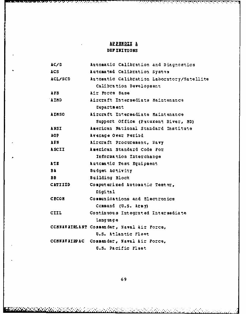
DEF INI TIONS
AC/D Automatic Calibration and DiagnCstics
ACS Automated Calibration Systsm
ACL/SCD Automatic Calibration Laboratory/Satellite
Calibration Develooment
AEB Air Force Base
AIND Aircraft Intermediate Maintenance
Cepartm ent
AINSO Aircraft Intermediate M£aintenance
Support Office (Patuxent River, MD)ANSI American Na:ional Standard Institute
AOP Average Over Period
AFN Aircraft Procurement, Navy
ASCII American Standard Code For
Information Interchange
ATE AutCmatic Test Equipment
B& Budget Activity
BB Building Block
CATIIID Computerized Automatic Tester,
Digital
CECON Communications and Electronics
Ccmmand (U.S. Army)
CIIL Continuous Integrated Intermediate
Lang uag eCCMNAVAIRLANT Commander, Naval Air Force,
U.S. Atlantic Fleet
CCHNAVAIEPAC Commander, Naval Air Force,U.S. Pacific Fleet
69
te- .

CCMSUBLANT Commander, Submarine Force,
U.S. Atlantic Fleet
CCMSURFLANT Commander, Surface Force,
U.S. Atlantic Fleet
CPI Consumsr Price Index
CRT Cathode Ray Tube
CSS Consolidated Systems Suppc -t
CSS Contractor Support ServicesCUE Commercial Test Equipment
CV Aircraft Carrier
CY Calendar Year
DAR Defense Acquisition Regulations
DARCOM Development and Readiness
Command (U.S. Army)
DNN Digital Multimeta=
.IA Defense Logistics Agency
DIF Determination and Findings
DOD Department of Defense
EOP End of Period
EUDOf Erasable Programmable Read Only MemoryEUE Electronic Test Equipment
FCA Fleet Calibration Activity
FBSO Fleet material Support Office
PiARS Flat Rate Measurement System
Fy Fiscal Year
GEIR GPITE End Item Replacement
GINO GPETE Initial Issue
GPETT General Purpose Electronic Test Equipment
GPIB General Purpose Interface Bus
GSA General Services Administration
GSE Grcund Support Equipment
GSI GPETE Support Item
70
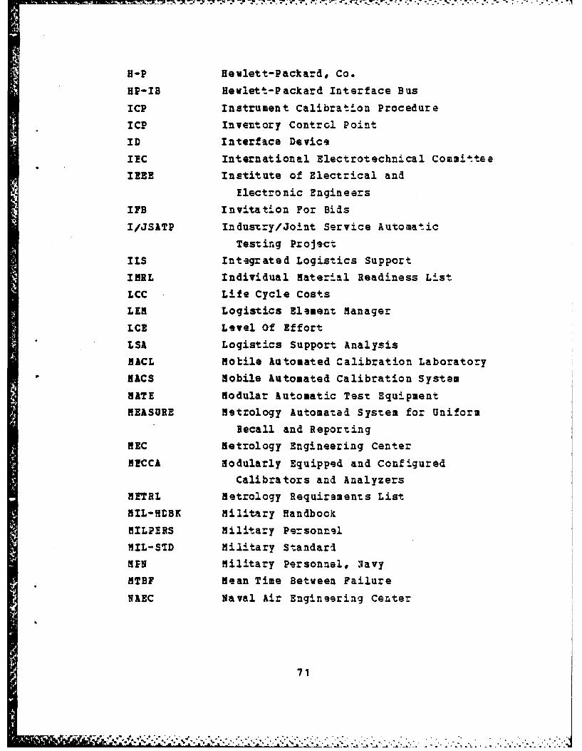
H-P Hewlett-Packard, Co.
HP-IB Hewlett-Packard Interface BUS
ICP Instrument Calibration Procedure
ICP Inventory Control Point
ID Interface Device
IC International ElectrotechnLcal Committee
IEEE Institute of Electrical and
*I Electronic EngineersIFB Invitation For Bids
I/JSATP Industry/Joint Service Automatic
Testing Project
ILS Integrated Logistics Support
INRL Individual Material Readiness List
LCC Life Cycle Costs
LEN Logistics Element Manager
LCE Level Of Effort
LSA Logistics Support Analysis
MACL Motile Automated Calibration Laboratory
RACS Mobile Automated Calibration System
RATE Modular Automatic Test Equipment
MEASURE Metrology Automated System for Uniform
Recall and Reporting
NEC Metrology Engineering Center
MCCA Modularly Equipped and Configured
Calibrators and Analyzers
METRL Metrology Requirements List
MIL-HDBK Military Handbook
MILPERS Military Personnel
MIL-STD Military Standari
MEN Military Personnel, 'Navy
MTBF Mean Time Between Failure
NAEC Naval Air Engineering Center
71

IALC Naval Aviation Logistics Command
NAHTD Naval Aviation Maintenance
Training Detachment
NARF , Naval Air Rework Facility
gaS Naval Air Station
NATC Naval Air Test Canter
NAVAIB Naval Air Systems Command
NAVCCMPT Navy Office of the Comptroller
NAVELEX Naval Electronics Systems Command
NAVMAT Naval Mate:-ial Command
NAVSTA Naval Sea Systems Command
NAYSUP Naval Supply Systems Command
NCL Navy Calibration Laboratory
NEC Navy Enlisted Classification Code
NESEA Naval Electronic Systems Engineering
Activity (St. Inigoes, MD)
NIP Navy Industrial Fund
NVS Naval Postgraduate SchoolNSF Navy Stock Fund
NS Naval Weapons Station
OJT On-The-Job Training
OBB Office of danagement and the_ Budget
08N Operations and Maintenance, Navy
OPN Other Procurament, .avy
CTS Of f-t he-S helf
PDV Present Discountad Value
PUCNICON Telephone Conversation
PaE Precision Measuring 2quipment
PCH Program Objectiva Memorandum
Q& Quality Assuranca
RADCCH Radar and Ccmmunications T.ster
Sal Science Applications, Inc.
72
-.. . . .e . - * .. .. M ..... .; . -... ..- ..-- ..-.-.-. - . ,.-. . . . .. ... .

SGE Supply and Equipage
SHAPE ShiF's Acquisition Manager
SH&D Source, Maintenance and RecoverabilitySo& State-of-the-Art
SPCC Ship's Parts Control CenterSPETE Special Purpose Electronic Test Equipment
SPETERL Ship's Portable Electronic/Electrical
Test Equipment Requirement.s List
STEAL Shore Tsst Equipment Allowancs List
SYSCCM Systems Command
TANS Test and Measuring Systems Office(NAVELEX Code DST)
TIK Tektronix, Inc.
TI Test Instrument
TINS Transmission Impairment MeasurementSystem
TMDE Test, Measuring and Diagnositic Equipment
USAF United States Air Force
VCR Video Cassette ascorder
WEN Weapons Procurement, Navy
73

ELECTRONIC TEST BQUIPHENT CLUSSIFICITIONS
Navy electronic test equipment (ETE) is classified by
the Naval aterial Command Electronic Test Equipment
Classification Board. The board consists of one representa-
tive frcm NAVAIR, NAVSE& and NAVELEX and is chaired by
NAYRLEX (an individual other than the NAVELEX rep=esenta-
tive) and meets as required to classify ETE into one of the
following three catagories:1. je__jj_ JuZ29_se 112-rpi T.s Equi S..' (E._).
GPET! is that electronic test equipment that is
capable of, without modification, or generating,
modifying or measuring a range of parameters of elec-
tronic functicns required to test two or mors
equipments or systems of basically different design.Newly designed and manufactured commercial off-the-
shelf (OTS) electronic test equipment (CTE) used to
support one system, will normally be classified as
GPETE if it is reasonable to predict its use will ba
required with more than one equipment or system.
Electronic test e quipment that is specifically
designed to generate, modify, or measure a range of
parameters of electronic functions of a specific or
peculiar "ature required to test a siagle system or
equipment, and it is reasonable to predict its use
with more than one system is unlikely.
3. O r E. Any test equipment -o-: considered as
either GPETE cr SPETE. (Ref. 54]
74
I ' ~ - ,-~
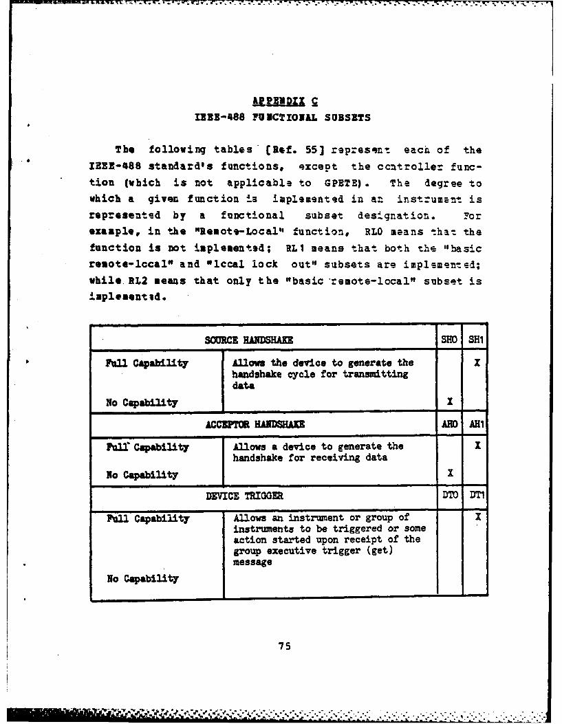
IBEB-488 FUNCTIOALM SUBSETS
The follovinq tables lefr. 55] represent each of the
13E-488 standard's functions, except the ccntroller func-
tion (which is not applicable to GPETE). The degree to
which a given function is implemented in a-- inst-ume .nt is
represented by a functional subset designation. 7or
example, in the "Reaots-Local" function, RLO means that the
function is not implemented; RL1 means that both t "basic
remote-lccal" and "iccal lock out" subsets are implemented;
while RL2 seans that only the "basic remote-local" subset is
ipl eenti d.
SOURCE HANDSHAKE SHO SHi
Ful Capability Allows the device to generate the zhandshake cycle for transmittingdata
No Capatlity I
ACCZPTOR HANDSHAKE AHO IA
Ful" Capability Allows a device to generate the Ihandshake for receiving data
No Capability X
DEVICE TRIGGER DM DTI
Full Capability Allows an instrument or group of Xinstruments to be triggered or someaction started upon receipt of thegroup executive trigger (get)message
No Capability
75
.. ..~ ~ ~ ~ ~~~6 ".M , - . .. ,, ,.,-,,............... ....... .,... .. . .1

- ~~C .CM .
> N3-r "
--
03 43 0- a .0 0
N2 S. N :N c
43~~ 4& go0 4 .N~~ A .04
N 43S
00
.10 V)*
UK4 4343e*I b
03.
C2 1
s~43 __ _ _ __ _ _
0~ 0 40
ca m
76

SERVICE REQUEST SRO SRI
Full Capability Allows an instrument to request Xservice from the controller withthe SRQ line
No capability X
O'.-LOCAL RLO M RL.2
Basi'c Remote-Local Allows the instrument to switch X Xbetween manual (local) controland prograimable (remote)operation
Local Lock-Out Allows the return to local Ifunction to be disabled
No Capability l
PARALLEL POLL PPO PP1 PP2
Basic Parallel Poll Allows an instrument to report I Ia single status bit to thecontroller on one of the datalines (D107-D108)
Remote Configuration Allows the instrument to be Xconfigured for parallel pollby the controller
No Capability XDEVICE CLEAR DCO DC1 DC2
Basic Device Clear Allows all instruments on the I Ito be'initialized to apre-defined cleared state
Selective Device Allows individual instruments to XClear be cleared selectively
No Capability I
77
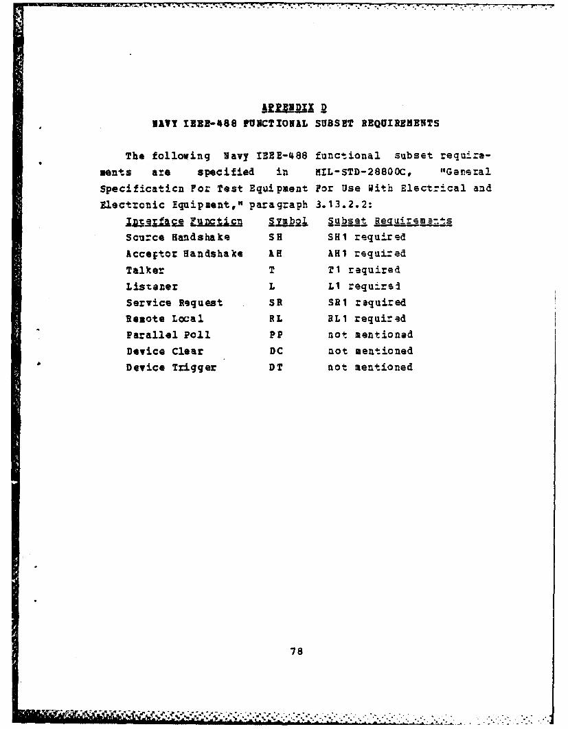
Z -'777 77 V; 77- 7 .......
NAV1IBZ2-488 FUNCTIONAL SUBSET REQUIREEBNTS
The following Navy IEEE-488 functional subset require-
vents are specified in NIL-STD-28800C, "Gereral
Specificaticn For Test Equipment For Use With Elect-rical and
Electronic Equipment," paragraph 3.13.2.2:
Scurce Handshake SH SH1 required
Acceftor Handshake AH AHI required
Talker T Ti required
Listener L Li requirsi
Service Request SR SRI required
Remote Local RL RL1 required
Parallel Poll PP not mentioned
Device Clear DC not mentioned
Device Trigger DT not mentioned
78
F -. ; :'if " , ' : ' . : ... ,, -... .. . . . . . . . . . . - ... . ..
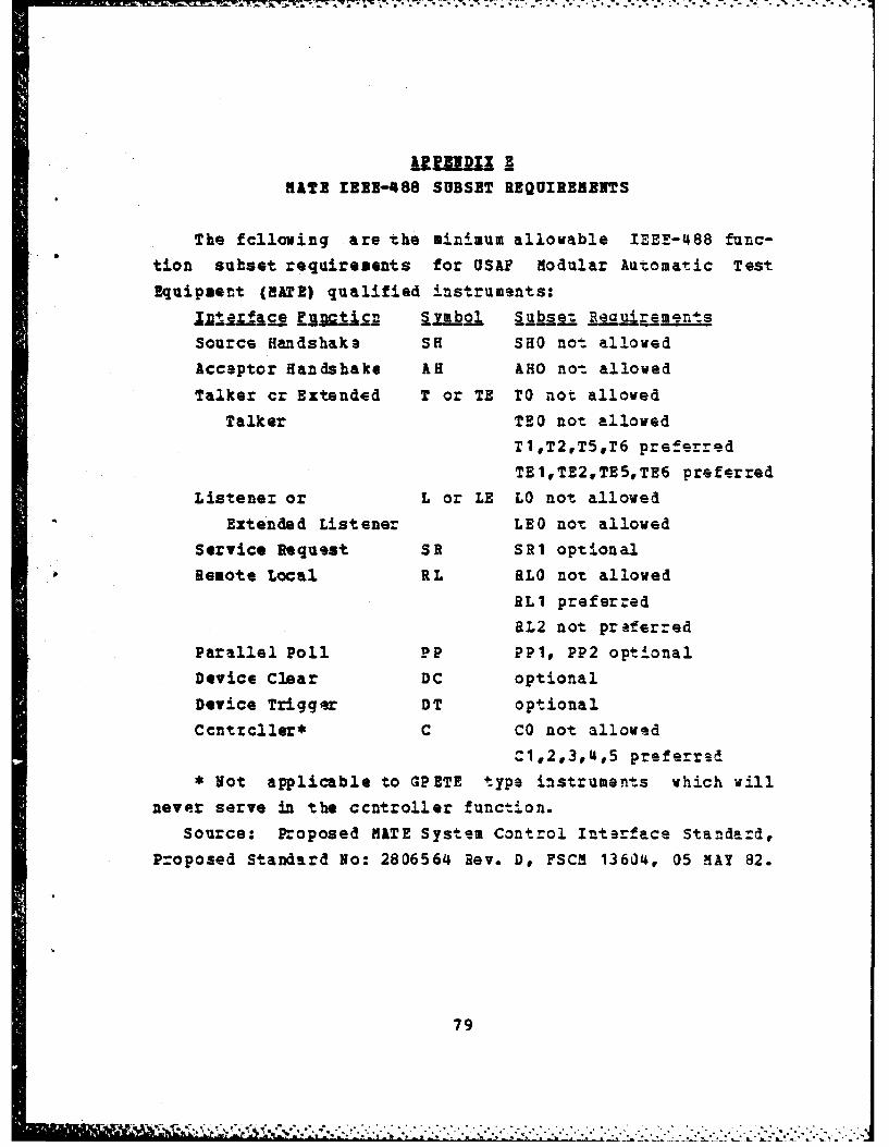
KATE IREI-488 SUBSET REQUIREMENTS
The fcllowing are the minimum allowable IEEE-488 func-
tion subset requirements for USAF Modular Automatic Test
Equipment (MATE) qualified instruments:
__ ol s__ _ e g m
Source Handshake SH SHO no'. allowed
Acceptor Handshake AH AHO no- allowed
Talker cr Extended T or TE T0 not allowed
Talker TEO not allowed
11,T2,T5.T6 preferred
TE1,TE2,TE5,TE6 preferred
Listener or L or LE LO not allowed
Extended Listener LEO not allowed
Service Request SR SR1 optional
Remote Local RL RLO not allowed
RL1 preferred
RL2 not preferred
Parallel Poll PP PP1, PP2 optional
Device Clear DC optional
Device Trigger DT optional
Ccntrcller* C CO not allowed
C1,2,3,4,5 preferred
Not applicable to GPETE type instruments which will
never serve in the ccntroller function.
Source: Proposed HATE System Control Interface Standard,
Proposed Standard No: 2806564 Rev. D, FSCM 13604, 05 MAY 82.
79
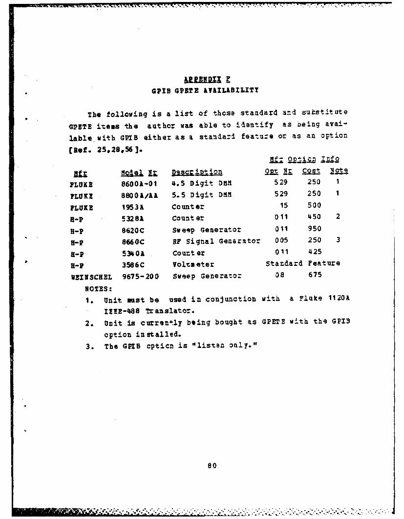
GPIB GPETE &VAILIBILITY
The following is a list of those standard and substitute
GPETE items the author was able to identify as being avai-
lable with GPIB either as a standa-I feature or as an option
(Ref. 25,28,56].
fl; .j~n nf o
W 1 1 p~sgript in Op-t Ii 9= lo
FLUKE 86001-01 4.5 Digit DMM 529 250 1
PLUKE 8800&/JLA 5.5 Digit DMN 529 250 1
FLUKE 1953A Counter 15 500
H-P 5328A Count er 011 450 2
H-P 8620C Sweep Generator 011 950
H-P 8660C RF Signal Generator 005 250 3
H-P 5340k ,Couter 011 425
fl-P 3586C Voltaeter Standard Feature
UEINSCHEL 9675-200 Sweep Genera:or 08 675
NOTES:
1. Unit must be used in conjunction with a Fluke 1120A
11E-488 Translator.
2. Unit is current ly being bought as GPETE with the GPI3
option installed.
3. The GPIB cpticn is "listen only."
80
:. .

-AC/C CONFERENCI ATTENDEES
The following individuals attended the AC/D conference
in Dallas, Texas, 29-31 3arch 1983.
Ins 11 k tv code
Don Tobey SAI, Dallas N/A
Richard Anderson NILC Det West 3022
John D. Crellin NALC Pat uxent River 3321
Walt Fitzgerald NALC Patuxent River 3322
Vernon Marsh NALC Det East 3012B3
Elton E. Artis NARF Norfolk, Type I 66010
Rick Renfro NAEF Alameda, Type II 66200
Emmett Parker NARF Alameda, Type III 66300
Wayne Porter NALC Det West SAI/NORIS
Joseph A. Walker NIS? Pensacola, Type III 94700
mike Foley WARF Pensacola, rype II 66400
Robert Sloccmb NARF Cherry Poin-t 94207
Doity Gaskill NARF Cherry Point 9420
V. (Pete) Grier NARF Cherry Point 52120
Gene Allert on DALFI, Inc., San Diego N/k
Barry Sanderson WARF Jacksonvill- 94461
Prank Brooks NARF Jacksonville 94400
Ken Icon NARP Jacksonville 94461
Jim Lcpez NARF North Island 94320
Terry T. Krogel NARF Nor'th Island 94325
Edward R. Greer NATC Pat uxent Rive= TS-243
Paul villenborg NAIC Patuxent Rive. TS-243
LCDR V.D. Stahler Naval Postgraduate School SMC 1689
Thomas Leedy National Bureau of Standards N/A
Los Scott Cerberonics Corp., San Diego NI/A
H. E. Bradley Naval Avionics Center 430H. T. Riebe Naval Avionics Canter 1432
81
Pster Sargent DALPI Corp., Oakland N/A
Elvin Speary SAI, Pat uxent RiVer N /A
G.. lintrop SAI, NCL Tustin NIA
82
Z'. .

.. . . . .... ,. . . . . . . . . . . . . . . . .
-r~ 77 - - . . 4. . .
kAPPZNDUX ffLIFE CYCLE CALIBRATION SAVINGS ANALYSIS
At the author's request NEC conducted a comparative
analysis of the time required to =onduct an open and closed
loop MECCA calibraticn. The test instrument used was the
FLUKE 9860A digital multimeter, the only instrument for
which bcth an open and closed loop ICP had be-sn develcp.d.
The test involved three technicians calibrating the instru-
sent using both techniques. Although the exact test figuresare not available for release, the -est showed an approxi-mate 50% reduction in the closed loop mode.
A survey was also conducted via phone conversations andquestionnaires to ascertain the estimates of individualsinvolved in automatic calibration system development and
familiar with MECCA. The following estimates were obtained:!iaje/icti ~ jvef eren ce EstimateHr. Hark Anderton 10-25%
CCHNAVAIRLANT 532B11
phcnecon of 29 Nov 1983
Mr. Robert Cole 25% or moreNEC Pomona
visit of 07 Jan 1983
Mr. Bobert Holcost 90%SAI NCL Tustinphonecon of 13 Jan 1983
Mr. Micheal Eagar 20%
NVS CraneQuestionnaire
Mr. Micheal Foley 25-30%NARF Pensacola Type II Lab
Questionnaire
83

7-. 7 17 -_31-.7
Mr. Paul illenborg 25I
NATC Patuzent River
Questionnaire
Mr. Sichard R-nfro 10%
NARF Alameda Type II Lab
Questionnaire
These results were presented at the AC/D Conference in
Dallas, Texas on 30 March 1983 (refs= to Appendix G for a
list of attendees) and the following 2anhouz reducticn
factors were agreed upon:
1. Conservative Estimate (current MECCA closed loop
prccedures) : 25%
2. Best Estimate (current MECCA closed loop procedures) :
30%
3. Best Estimate (revised MECCA closed loop procedures) :
50%
84
*.1
.2 - -. -
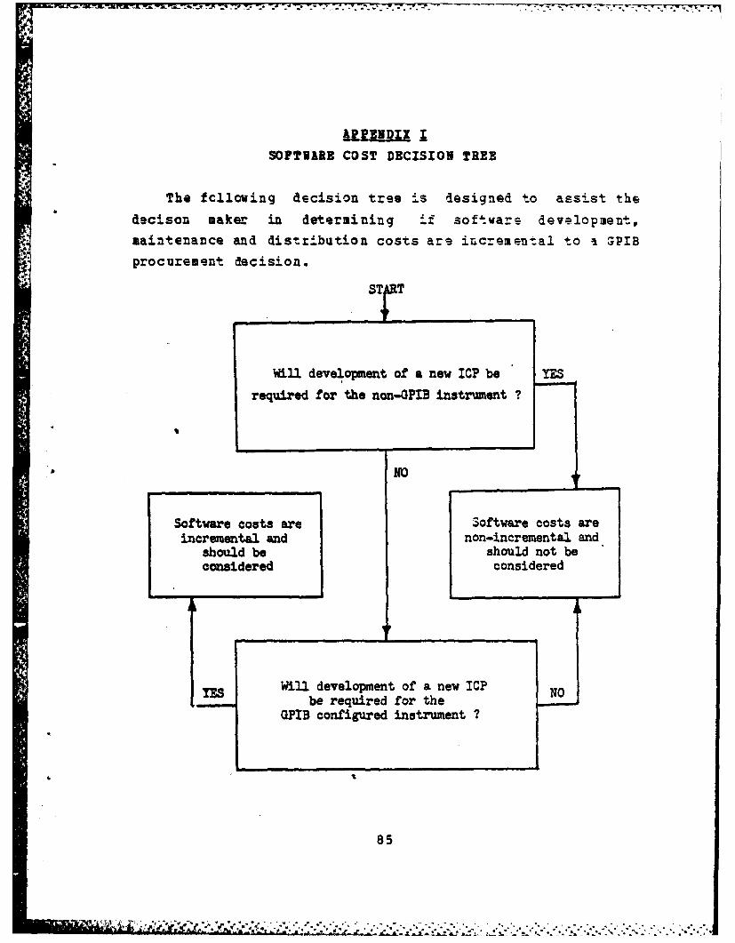
SOFTUARE COST DECISION TREE
The fcllowing decision tree is designed to assist the
decison maker in determining if softwars development,
maintenance and distribution costs are increment.al to a GPIB
procurement decision.
Will development of a new ICP be YES
required for the non-OFIB instrument ?
NO
Software costs are Software costs areincremental and non-incremental and
should be should not beconsidered considered
Will development of a new ICP NObe required for the
GPIB configured instrument ?
8L
85
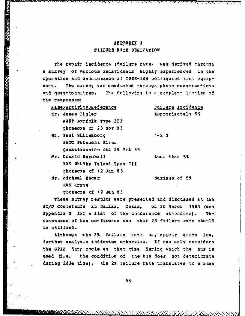
11PENDIX JFAILURE RATE DERIVATION
The repair incidence (failure rate) was derived througha survey of various individuals highly exp.rlenced in theoperation and maintenance of IEEE-488 configured test equip-
ment. The survey was conducted through phon conversationsand questionnaires. The following is a complet lis-ting of
the responses:
1A e/ c 1=112M. 2- alure IncidnceHr. James Cigler Approximately 5%
NIEF Norfolk Type IIIphcnecon of 23 Nov 83
Hr. Paul Willenborg 1-2 %
SATC Patuxent RiverQuestionnaire dtd 24 Feb 83
Mr. Dcnald Marshall Less than 5%NIS ihidby Island Type III
phcrecon cf 12 Jan 8.3Hr. Micheal Eagar Maximum of 5%
NIS Crane
phcnecon of 17 Jan 83
These survey results were presented and discussed at theAC/D Ccnference in Dallas, Texas, on 30 March 1983 (see
Appendix G for a list of the conference attendees). The
concensus of the conference was that 21 failure rate should
be utilized.
Although the 2% failure rate may appear quites lcw,further analysis indicates otherwise. If one only considers
the GPIB duty cycle as that time during which the bus is
used (i.e. the condition of the bus does not deteriorate
during idle time), the 2% failure rate translates to a mean
86
.A..
-
time between failure (MTBF) of only 94.5 hours ((.7 X 2.7hrs/calibrat!on)/(.02 failures/calibration)) for the exampl e
used in Appenix S.
This MTBF is significantly lower than that calculated bytest equipment manufacturers during warranty repor-: r,¶-
tion. Tic eumples are offered.1. Hewlett-Packard's warranty report on the 8672 signal
generator estimates the IEE-488 bus (HP-IB) failurerate at .2% per year (based upon 2000 hours per
year). This translates to a MTBF of 1,000,000 hcurs,fcur orders of magnitude greater than the rate- usedin this analysis. Additionally, H-P calculated that
the HP-IB only contributed .9% to the overall failure
rate of the instrument. This failure rate, however,is based on an instrument not connected to another
instrument or controller. It, therefore, does notinclude the failure rate of the GPIB connector.(Ref. 57]
2. Tektronix has calculated the failure rate of a GPIB
cable (with two connectors) as .0324 per 1000 hours.This translates to a MTSF of nearly 31,000 hours.
(let. 58]Because of these low failure rates, the incremental fee
that manufacturers charge for inclusion of GPIB option
coverage in their annual repair agreements is ve:y small(most often zero). Examples are provided in Appendix L.
87

i 16 V .U :; Tw C. LN1 1 -X - - . - r &%
IIIUDI I
IRIEBS-488 REPAIR ANHOURS AID MATERIAL COSTS
The average cost of an IEEE-488 reoair in terms of
manhours and materials was established through interviews
with and the completion of questionnaires by various indivi-duals experienced with bus repair. The following is asample of the responses:
V,4 L siaif erea3& faho2s r =ofr. James Cigler 2 $ 20-25
ARF orfclk Type II
phonecon of 23 Nov 83
Mr. Paul Villenborg 2 S 25
HATC Patuxent River
Questionnaire dtd 24 Feb 83
Mr. Donald Marshall 2 $ 25WAS Vhidby Island Type II
phcnecon of 12 Jan 834r. Craig Gaby 2 (if bus controlled by
Hewlett-Packard separats microprocsssor)
Service Cantor, Atlanta 6 (if bus and instrument
phcnecon of 18 Jan 1983 controlled by a single
mic=oprocessor)The results of this survey were discussed at the AC/D
Conference in Dallas, Texas on 30 larch 1983 (for a list of
attendees see Appendix G). The discussion resulted in anestimate cf 3 manhcurs and $40 of mate.ial for an average
repair action. The primary justification given for these
relatively low averages was that a high percentage of GPIB
repairs cnly involve reseating a circuit card.
88
-€ ., -* -

Further Justification f or these low average -3xpsrd-itares
comes frcs the following:
1. The incremental charge for inclusion Of -hz GPIB
cpticu in a manufacturer's aanual rapair agreemen-t is
*small,, most often zero (see AppendirX L for eXampla-s).
*Since electrcnics firms are in business to make
money, it can be assumed that the GPIB is -not only
reliable, but is also relatively inexpensi-.ve to
repair.
2. The parts invclved in GPIB -mplqmenta-:ion are gener-
ally inexpensive. The following examples
(Ref. 59,60] illustrate:
Texas Inst. 9914A GPIB Integrated Circuit S16.00
SN160 Buffer 5.00
SN162 Buffer 6.50
HP-IB Internal Cable (H-P 5328k Counter) 16.50
HP-IB Circuit Card (H-P 5328k Counter) 206.00
89
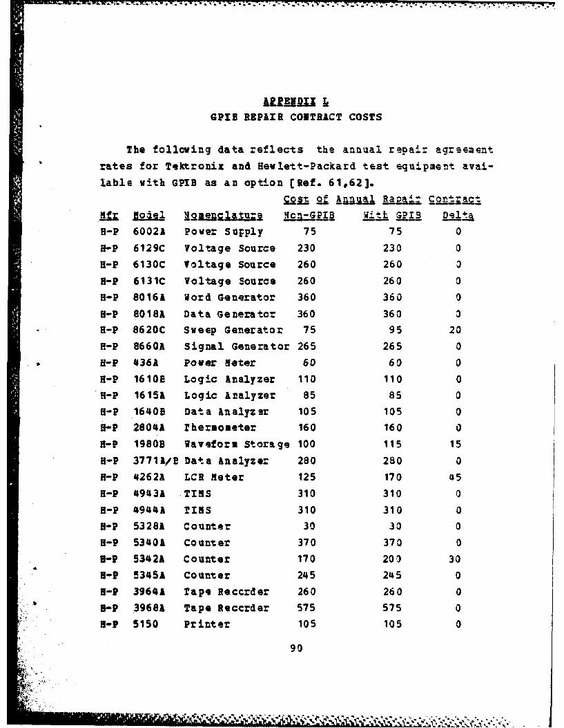
&Ui E.I z !
GPIB REPAIR COITR&CT COSTS
The following data reflects the annual repair agreement
rates for Tektronix and Hevlett-Packard test equipment avai-
lable with GPIB as an option [Ref. 61062].Colt of Annual RaZL _CotrcIt
B-P 6002A Pover Supply 75 75 0
H-P 6129C Voltage Source 230 230 0
H-P 6130C Voltage Source 260 260 a
a-P 6131C Voltage Source 260 260 0H-P 8016A Word Generator 360 360 0
H-P 8018A Data Generator 360 360 0
H-P 8620C Sveep Generator 75 95 20
f-P 8660k Signal Generator 265 265 0H-P 436A Pover meter 60 60 0
H-P 1610E Logic analyzer 110 110 0f-P 1615A Logic Analyzer 85 85 0H-P 16140E Dat a An alyz er 105 105 0
H-P 2804A Thermometer 160 160 0
H-P 1980B Waveform Storage 100 115 15
H-P 37711/! Data Analyzer 280 280 0
H-P 4262A LCR Meter 125 170 45
f-P 49431 TIS 310 310 0l-P 4944A TINS 310 310 0
H-P 53281 Counter 30 30 0HP 53401 Counter 370 370 0U-P 5342* Counter 170 203 30
H-P 5345A Counter 245 245 0
H-? 3964* rape Reccrder 260 260 0
3f-P 3968* Tape Reccrder 575 575 0B-P 5150 Printer 105 105 0
90
;:" " * . ',.
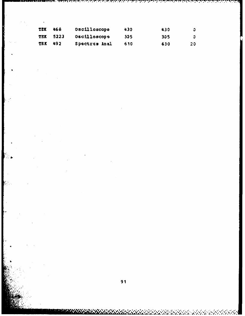
T-- C 777. - -77 LN -7 7 -77--C
TEN 468 oscilloscope 430 430 0
TEN 5223 oscilloscope 305 305 3TEK 492 Spectrum Anal 610 630 20
91
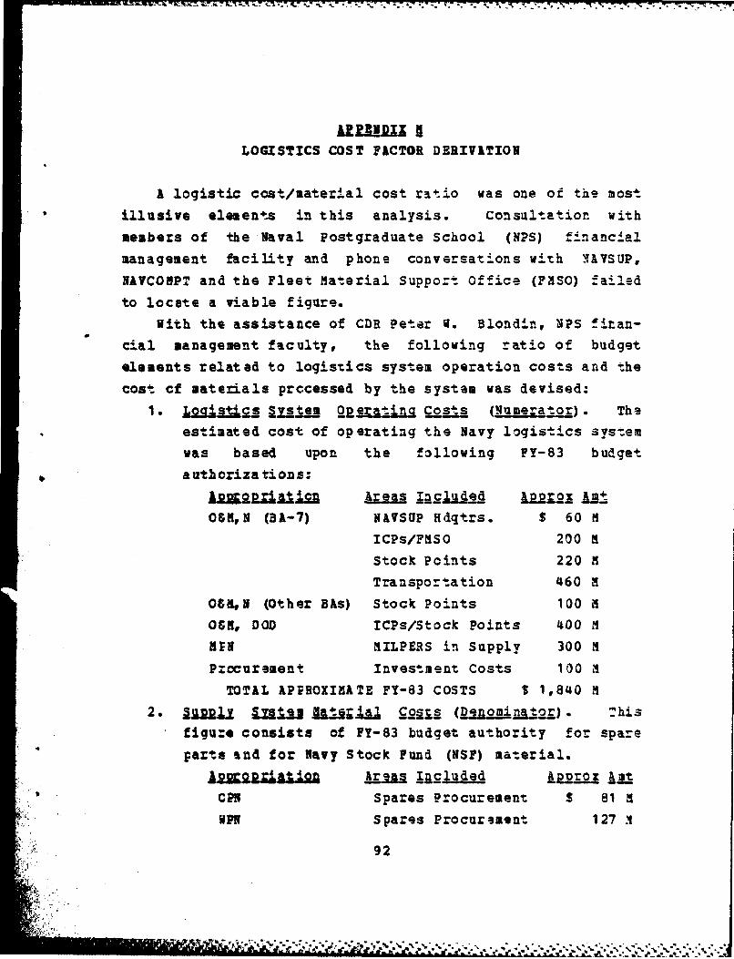
Vl£A. 4k - -- .- K77 - 7
iUnIDIX aLOGISTICS COST FACTOR DERIVATION
A logistic cost/material cost ratio was one of the most
illusive elements in this analysis. Consultation with
members of the Naval Postgraduate School (NPS) financial
management facility and phone conversations with IAVSUP,
NAVCOMPT and the Fleet Material Suppor-t Office (FPSO) failed
to locate a viable figure.
With the assistance of CDR Peter W. Blondin, NPS finan-
cial management faculty, the following ratio of budget
elements related to logistics system operation costs and the
cost cf materials prccessed by the system was devised:
1. L2g l §ysi__ ej i__." _ Qoai (sumerao). Theestimated cost of operating the Navy logistics sys.emwas based upon the following FY-83 budget
autbcr1zatios:
1R2a2Iarl"=f Areas xaslud LpZx AmtO$K, N (BA-7) NAVSUP Hdqtrs. $ 60 M
ICPs/FMSO 200 M
Stock Points 220 M
Transportation 460 M
OSN,M (Other BAs) Stock Points 100 L
OGM, DOD ICPs/Stock Points 400 M
ANr MILPERS in Supply 300 ,M
Procurement Investment Costs 100 M
TOTAL APPROXIMATE FY-83 COSTS $ 1,840 M2. Su l LUJ Uj ial g.2111__ (Denonator). T'his
figu:e consists of FY-83 budget authority for spare
parts and for Navy Stock Fund (NSF) material.
iaR"a1t i nga lagaA~ kpo nit
CPS Spares Procurement $ 81 i
WPN Spares Procurement 127 A
92

-- -* --I - .. . -' . .- -
APN Spares Procurement 1,998 m
NSF (Osm, N) Spares Procurement 3,000 1
Other Stock Funds Spares Procurement 9CO m
C&3 ,N (BA-7) Eng/Component Rework 1,034 M
TOTAL APPROXIMATE FY-83 Costs 7,030 m3. .L.g q.I .ria C o. Division. of the
logistics costs ($1,840 M) by the total material
costs ($7,030 1) yields .2617 (26.171).
This 26% figure grossly understates (perhaps by as much
as 100%) the actual cost ratio because of T.he abssncs o-:
several major logistics system cost elements which were not
available. Among these absent cost elements ar.9 thefollowing:
1. Ccat 2 L Z LCJ SuV.E2 . 2t. The Navy employsnumerous supply support ships to deliver supplies to
the operating units. The above logistics system costestimates do not include any costs for theiroperation.
2. Ccs g& LoaisA .aE i-a. A good portior of theNaval material Command and its associated systemscommands (other than IVASUP) are directly involved in
the planning and programming of logistics supportwithin the Navy. This involvement includes both the
acquisition cf major systems and the logistical
support of these systems. Since it was not possible
to segregate individual costs of supply support fromother major logistical areas, no cost for the Naval
Material Command or its systms command (other thanNAYSUP) have been included.
If a true ratio could be calculated it would lis some-
where between 25% and 55% [Ref. 63]. In this analysis the
mid-point of this range, 40%, will be used for the logistics
cost factor. Fortunat ly, as demonstrated in the sensi-tivity analysis (Appendix T) the accuracy of this factor is
93

not critical to the analysis. In fact, the dif f arence in
the modl's outpizt using 25% factor as compared to a 555
fact r is ctly $1.10.
9
4
94
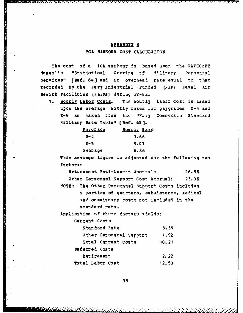
-'0
AI9PENDIXPC& HINHOUR COST CALCULATION
The cost of a ECA manhour is based upon -the NAVCOMPT
Manual's "Statistical Costing of Military Personnel
Services" (Ref. 64] and an overhead rate equal to that
recorded by the Navy Industrial Funded (XIF) Naval Air
Rework Facilities (NARFs) during FY-82.
1. _Hcur k.bgr Ccst. The houly labor cost is based
upon the average hourly rates for paygrades E-4 and
E-5 as taken from the "Navy Compvosit e Standard
Military Rate Table" (Ref. 65].
La.czrd Houj jqte
E-4 7.66
E-5 9.07
Average 8.36
This average figure is adjusted for the following two
factors:Retirement Entitlement Accrual: 26.5%
Other Perscnnel Support Cost Accrual: 23.0%
NOTE: The Other Personnel Support Costs includes
a porticn of quarters, subsistence, medicaland commissary costs not included in thestandard rate.
Application of these factors yields:
Current CcstsStandard Rate 8.36
Other Personnel Support 1.92Total Current Costs 10.21
Deferred Costs
Retirement 2.22Total Labor Cost 12.50
95

A, -A133 865 GENERAL PURPOSE ELECTRONIC TEST EQUIPMENT (GPETE) 2/2ACQUISITION CONSIDERRTIONS FOR AUTOMATED CALIBRATION(U) NAVAL POSTGRADUATE SCHOOL MONTEREY CA N D STRNLER
UNCLASSIFIED JUN 83 NP554-8 -802 F/G 9/2 NL
IlllIIsollllllIEEL
- - - '- - - * .2i. ~
111 [0 'W
MICROCOPY RESOLUTION TEST CHART1ATONA 1EAU OF STANDARD- 963-A

2. O erhal 3a. The overhead application of CI
funded activities during FY-82 was calculated fom
the Department of the Navy, Office of Comptzol'er,
NNavy Industrial Fund" Report for the period ending
30 September 1982. The following figures are takenfrom the NARF section of that report:
Direct Labor $ 372,083,000Cverhead Labor 337,557,000
ovrhead Haterials & Services 255,511,000The overhead rate was calculated by dividing totaloverhead by direct labor, yielding 1.59.
3. giz QZra jA9 ajd Co_.1 To avoid charging overhead
against a deferred labor cost (retirement) , the over-head rate is applied only to the curren-t hourly labor
cost (standard rate and other personnel supportcosts). Therefore, the hourly overhead charge e.qualsthe current hourly labor cost ($10.28) multiplied by
the overhead rate (1.59) = $16.35.4. TIS J Cot o! 21 CA Snhour. The hourly FCA
cost equals the total hourly labor cost ($12.50) plus
the hourly overhead cost ($16.35) = $28.85. This
figure is rounded down to $28 per hour for use in the
cost-benefit model.
It is recognized that many substantive arguments can bemade against the derivation of this figure. It could be
argued that application of an overhead charge is invalid for
a shipboard FCA because the facility cost would r=mainuncharged even if a man was eliminated. It might also beargued that the overhead charge is actually too low consid-ering the size of the lavy support establishment and therelatively fcrward Ecsition of the FCk in that structure.Similar legitimate assaults could be made cn practically
every facto: in this derivation. Ho wever, no other figureexists and this figure is not cut of line with the relat.d
hourly rates discussed in the following paragraphs.
96
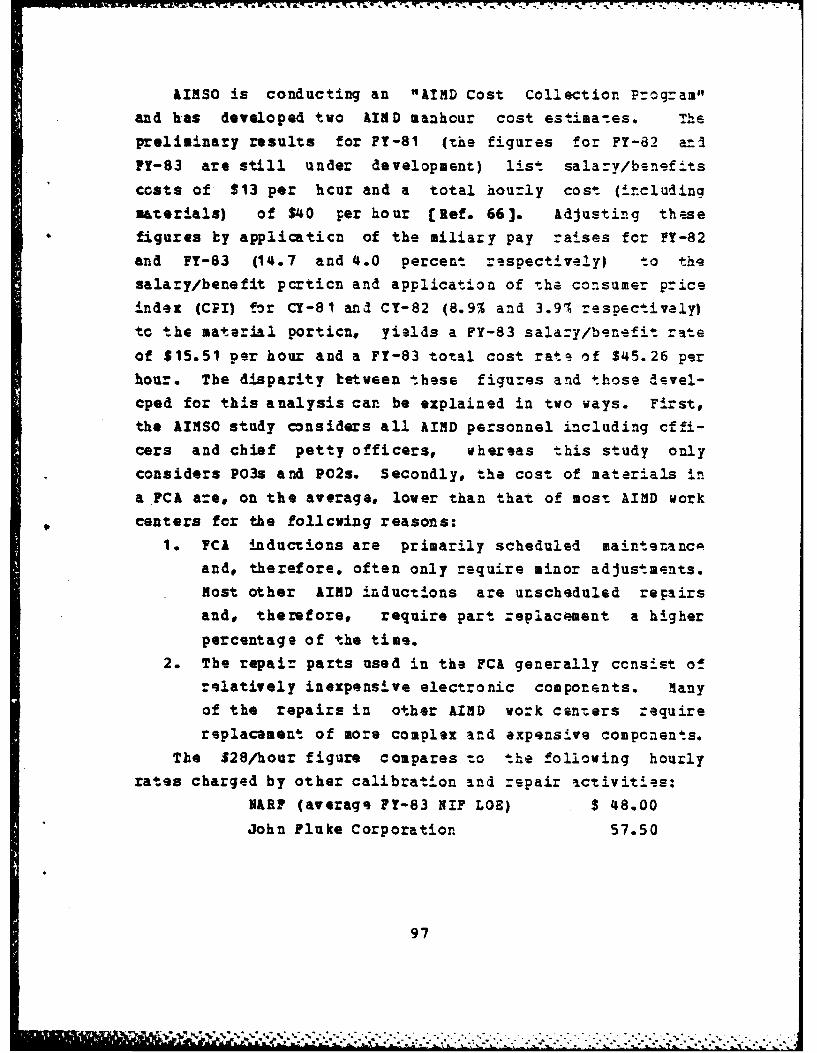
AIRSO is conducting an "AIMD Cost Collection Program"
and has developed two AIND manhour cost estima-es. Thepreliminary results for FY-81 (the figures for FY-82 an IPY-83 are still under development) list salary/b-nefits
costs of $13 per hcur and a total hourly cost (i..cluding
materials) of $40 per hour [Ref. 66]. Adjusting the.sefigures by applicaticn of the iliary pay raises for PY-82and PY-83 (14.7 and 4.0 percent re.spectively) to thesalary/benefit pcrticn and application of the consumer priceindex (CPI) for CY-81 and CY-82 (8.9% and 3.91 respectively)to the material porticn, yields a FY-83 salary/benefit rateof $15.51 per hour and a PY-83 total cost rats of $45.26 perhour. The disparity between these figures and those devel-cped for this analysis car. be explained in two ways. First,the AIRSO study considers all AIND personnel including cffi-cers and chief petty officers, whereas this study onlyconsiders PO3s and P02s. Secondly, the cost of materials ina PCk are, on the average, lower than that of most AIND workcenters for the follcwing reasons:
1. PCA inductions are primarily scheduled maintenancAand, therefore, often only require minor adjustments.
Most other LIND inductions are unscheduled repairs
and, therefore, require part replacement a higher
percentage of the ties.2. The repair parts used in the FCA generally ccnsist of
relatively inexpensive electronic components. Manyof the repairs in other AIND wozk centers zequire
replacement of more complex and expensive compcnents.The S28/hour figure compares to the following hourly
rates charged by other calibration and repair activities:MAR? (average FY-83 NIP LOE) $ 48.00
John Fluke Corporation 57.50
97
a a .. *. ~ ~ ***

Tekt ronix 60.00
Havlett-Packard 65.00
98

DISCOUNTING AID THE DISCOUNT FACTOR TABLE
Discounting is a technique used to adjust future cash
flows to their current value (present discounted value
(PDV)). "The present value of $1 payable next year isS/(1.r). This is the amount which, if invested -oday at an
annual interest rate r, will y ald $1 in one year."(Ref. 67] Therefore, the further an expected cash flw is
into the future, the less its value will be in current
terms. The discount factor (provided below) is the decimal
fraction used to reduce future cash flows to their present
value (PDV).
In accordance with DOD Directive 7041.3 and OMB Circular
A-914, a ten percent discount rate will be utilized in this
analysis. The discount rates used will be "average" factorsvice "end of the year" factors for the following reasons:
The raticrale for us-ng average factors instead of end-of-the-year factors ts essentially twofold:
1. afte the initial investment cost, most of theannual costs and benefits associated with aroject do not occur at a single point in timetu ratkber are spread throughout the year. This
is typc aly. -rue of operating costs andsalar es. S h costs are best aporoximated by anannual lump payment occurring it the middle ofthe year.
2. T e exact tie of occurrence of costs and bene-i .2 n ut ears of an economic life may not be
nf wit h ertainty. In the asevnce of moreci fic information, there is no reason to
asue that these costs and benefits will occurcily on the anniversaries 9 f .acquis-ion- theyalaht occur at ay pont .n -he year. Iverag .faetors are genelaly applied to such costs.11rors on the low side should occur about asoften as errcrs o. the high side. In the longunt. tore will be an offsetting effect.
99
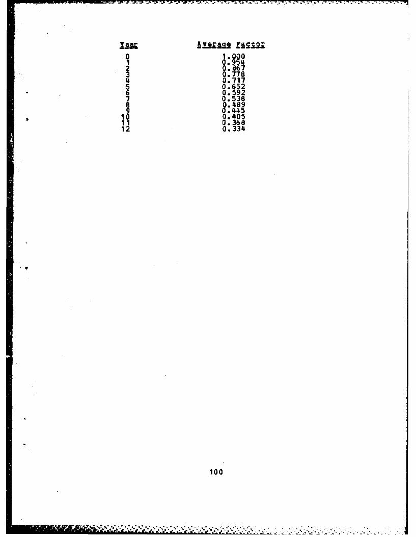
0. 9542 0.*867
3 0.7784 0.7175 0.652
* 6 0.5927 0.5388 0.4899 0.445
, 10 0.40511 0.36812 0.334
100
*1
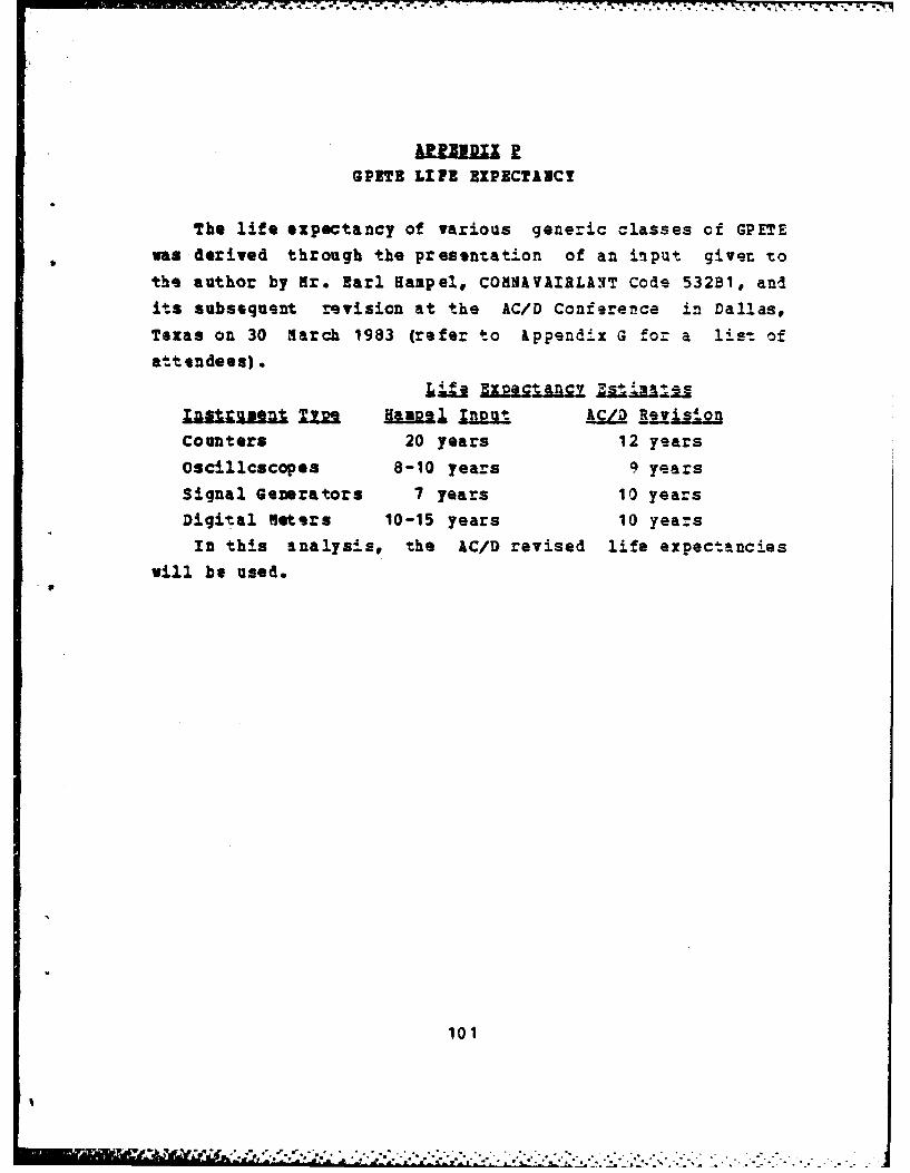
GPITS LIFE EIPECTAIC!
The life expectancy of various generic classes of GPETEwas derived through the presentation of an input giver tothe author by Mr. Earl Sampel, COMNAVAIRLANT Code 532B1, andits subsequent revision at the AC/D Conference in Dallas,
Texas on 30 Harch 1983 (refer to ippendix G for a 1is-t ofattendees).
Life Exetnl j
"AaZ.;usl Im Have Inu ReatVisionCounters 20 years 12 years
Oscillcscopes 8-10 years 9 years
Signal Generators 7 years 10 years
Digital meters 10-15 years 10 yearsIn this analysis, the AC/D revised life expectancies
will be used.
101
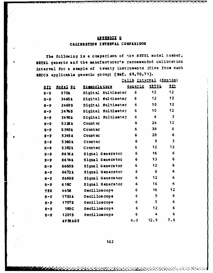
1.7 7. 77 - 77"77-7 -7- .P
I&U.UDU 2CALIBRATIOI IITEVAL COMPARISON
The fclloving is a comparison of the METRL model number,
iETEL generic and the manufacturer's recomaended calibration
interval for a sample of twenty instruments (five from each
HECCA applicable generic group) [Ref. 69,70071].
H-I 970A Digital Multimeter 6 12 12
f-P 3465k Digital dultimeter 6 12 12
H-P 3469B Digital dultimeter 6 10 12
H-P 3476B Digital dultimeter 6 10 12
fl-P 34901 Digital ultimeter 6 6 3
H-P 5328A Count er 6 24 12
H-P 5340A Counter 6 38 6
H-P 53451 Counter 6 20 6
f-P 5360k Ccunter 6 9 3
R-P 5382A Ccunter 6 12 12
H-P 8616A Signal Generatcr 6 16 6
H-P 8614A Signal Generator 6 13 6
H-P 8660B Signal Generator 6 12 6
H-P 86721 Signal Generator 6 6 6
H-P 86608 Signal Generator 6 12 6
H-P 618C Signal Generator 6 16 6
TEK 4658 Oscilloscope 6 16 12
H-P 1703k Oscl los cope 6 5 6
f-P 1707B Oscilloscope 6 5 6
f-P 180C Oscilloscope 6 12 6
H-P 12019 Oscilloscope 6 4 6
AVIRAGE 6.0 12.9 7.8
102
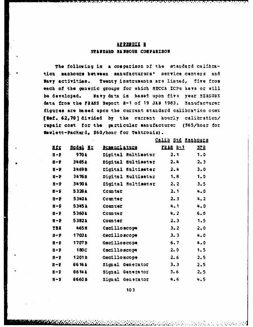
- -- - . q- - .'- . . T ' - -. , -. * - -%
* - - - -. " -
"UUU ISTINVARD S HOUR CONPARISON
The following is a comparison of the standard cal.bra-
tion manhours between manufacturars' service centers and
Navy actlvi t ies. Twenty instruments are listed, five from
each of the generic groups for which MECCA ICPs have or will
be developed. Navy data is basel upon five year .1EASUREdata from the FRANS Report R-1 of 19 JAN 1983. Manufacturer
figures are based upcn the current standard calibration cost
[Ref. 62,70] divided by the current hourly calibration/repair coat for the particular manufacturer ($65/hour for
Hewlett-Packard, S60/hour for Tektronix).Calib §Id nakjs
B-P 9701 Digital Iultimeter 2.1 1.0
H-P 3465A Digital Nultimeter 2.4s 2.3H-P 34699 Digital Hultimeter 2.4 3.0H-P 3476B Digital Hultimeter 1.8 1.0H-P 3490A Digital Hultimeter 2.2 3.5
H-P 5328A Ccunter 2.1 4.0H-P 531401 Ccunter 2.3 '4.2
H-f 53451 Counter 4.1 4.0
H-P 5360A Ccunter 4.2 6.0
H-P 53821 Counter 2.3 1.5
TEX 4655 Cacilloscope 3.2 2.0
H-P 1703A Oscilloscope 3.3 '4.0
H-P 1707B Oscilloscope 6.7 4.0
H-P I80C Cacilloscope 2.0 1.5H- 1 201B Oscilloscope 2.6 2.5H-E 8616A Signal Gene:ator 3.3 2.5
H-P 8614A Signal Generator 3.6 2.5
H-P 8660B Signal Generator 4.6 4.5
103
[ _ ,, , r ,e , , ,;,. I.; .. -,-.. . ..-. .. . ,. . . .. . .,
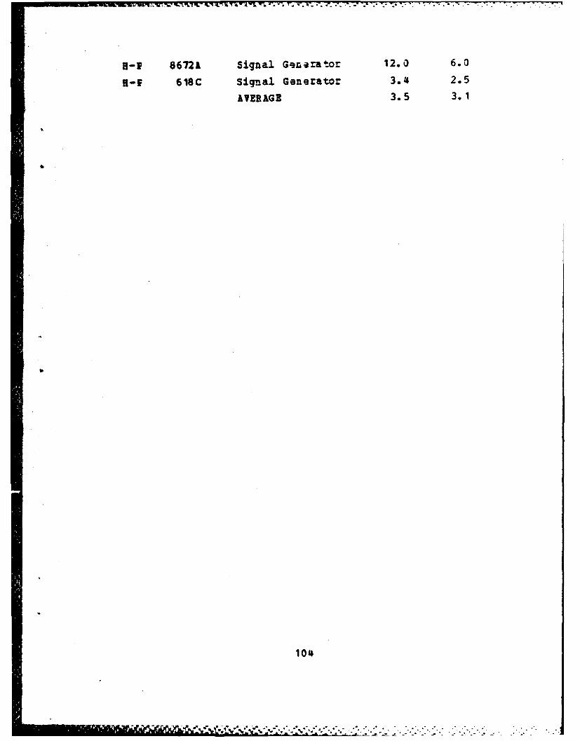
_~~~~T V'. •..
H-P 8672A Signal Generator 12.0 6.0
H-f 618C Signal Generator 3.46 2.5
AvERAGE 3.5 3.1
I1
104
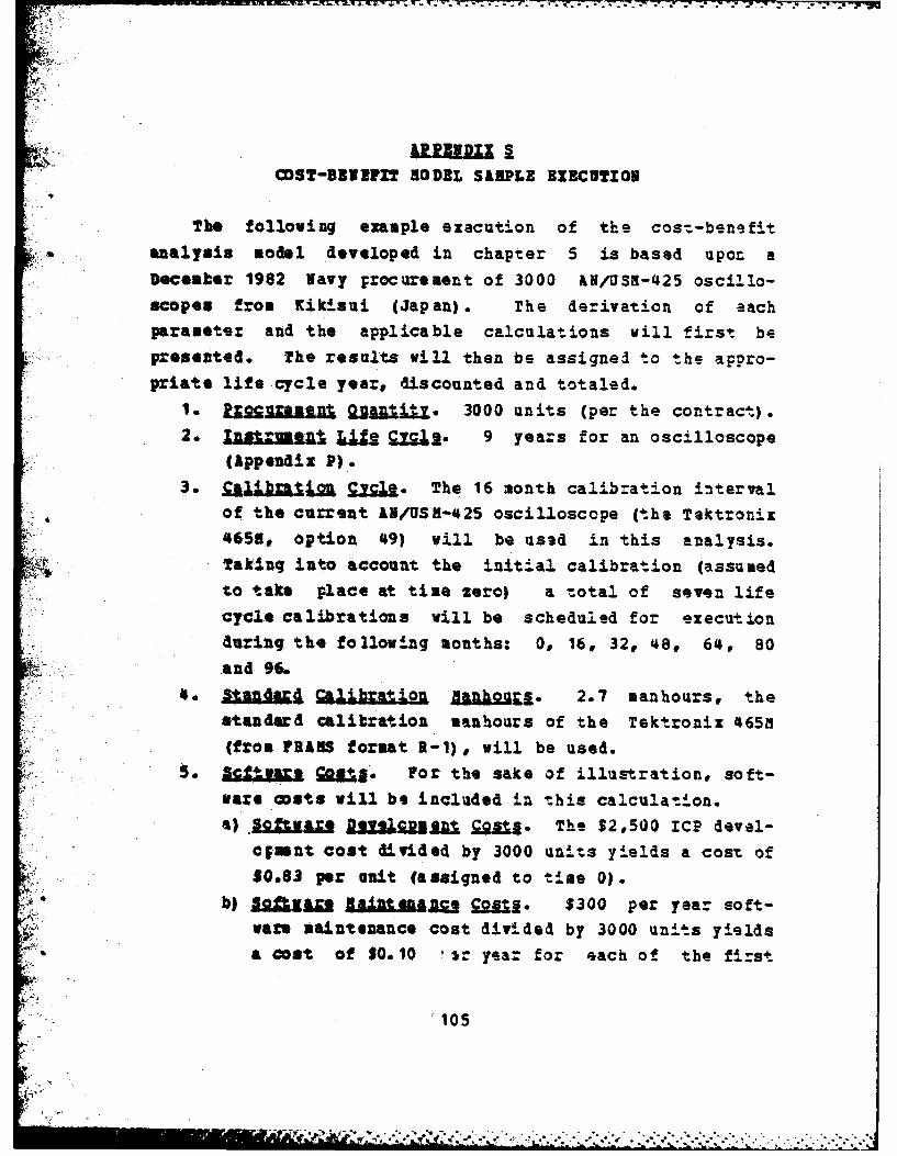
COST-BII"IT MODEL SAMPLE EXICUTION
The following example execution of the cos,-benefitanalysis model developed in chapter 5 is based upon aecember 1982 Navy procurement of 3000 AN/USM-425 oscillo-
scopes from Kikisui (Japan). The derivation of eachparameter and the applicable calculations will first bepresented. The results will then be assigned to the appro-priate life cycle year., discounted and totaled.
1. LUMBMlj 21= a 3000 units (per the contract).2. I gruen 3 ;=.t. 9 years for an oscilloscope
(Appendix P).
3. a.ibraZion, Cycle. The 16 month calibration intervalof the current &N/USN-425 oscilloscope (the Tektronixi4658, option 49) will be used in this analysis.
Taking into account the initial calibration (assumedto take place at time zero) a total of seven lifecycle calibrations will be scheduled for executionduring the following months: 0, 16, 32, 48, 64, 80
and 96.
4o: e I4Ol alik21 Hanh"ura. 2.7 manhours, thestandard calibration manhours of the Tektronix 4651(from FR&AS format 2-1) , will be used.
5 §Cljj.arx For the sake of illustration, soft-ware costs will be included in this calculation.a) Seaman Dlsus0aui J . The $2,500 ICP devel-
c;mnt cost divided by 3000 units yields a cost of
0.83 per unit (assigned to time 0).
b) ,ajft n Raina 20 JM,,.. $300 per year soft-wan- maintenance cost divided by 3000 units yields
4b a cost of $0.10 sr yea= for each of the first
105
,'-*-- ' ' . . . - ..
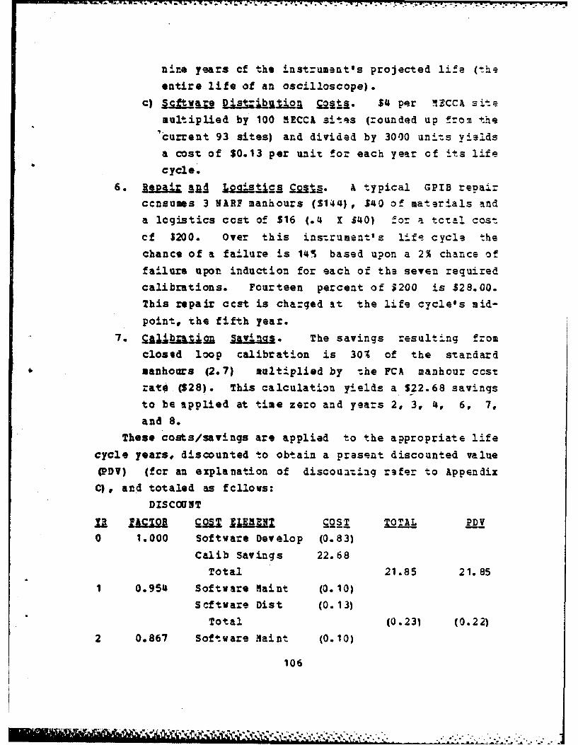
nine years of the instrument's projected life (the
entire life of an oscilloscope).
c) §=!_La Dit="Lt 2A o£2!t. $4 per 11ZCCA sitemultiplied by 100 MECCA sites (rounded up from the
'current 93 sites) and divided by 3000 units yieldsa cost of $0.13 per unit for each year of its life
cycle.
6. eva qjd L agigc A & typical GPIB repairccnsums 3 NARP manhours ($144) , $40 of materials and
a logistics ccst of $16 (.4 X $40) for a tctal cost
cf $200. Over this instrument's life cycle the
chance of a failure is 14 based upon a 2% chance of
failure upon induction for each of the seven requiredcalibrations. Fourteen percent of $200 is $28.00.
This repair ccst is charged at the life cycle's mid-
point, the fifth year.
7. £ij oin Savings. The savings resulting from
closed loop calibration is 301 of the standard
anhours (2.7) multiplied by the FCA manhour costrat4e ($28). This calculation yields a $22.68 savings
to be applied at time zero and years 2, 3, 4, 6, 7,and 8.
These costs/savings are applied to the appropriate lifecycle years, discounted to obtain a present discounted value(PDV) (for an explanation of discouating refer to Appendix
C), and totaled as f llows:DISCOUNT
YJ QATR a LMAN OT TTX PDV0 1.000 Software Develop (0.83)
Calib Savings 22.68Total 21.85 21.85
1 0.954 Software Maint (0. 10)Software Dist (0.13)
Total (0.231 (0.22)
2 0.867 Software Naint (0.10)
106
m i n Ii in ' ~ a : ' - ! ,, ' ,, -,; . .[,.'. . .. o

Software Dist (0.13)
Calib Savings 22.68
Total 22.45 19.46
3 0.778 Software Maint (0.10)
Software Dist (0. 13)
Calib Savings 22.68
Total 22.45 17.147
4 0.717 Software naint (0.10)
Scftware Dist (0.13)
Calib Savings 22.68
Total 22.45 16.10
5 0.652 Software Maint (0.10)
Software Dist (0.13)
Repair/Logistics (28.00)
Total (28.23) (18.41)
6 0.592 Software Maint (0.10)
Software Dist (0.13)
Calib Savings 22.68
Total 22.45 13.29
7 0.538 Software maint (0. 10)
Software Dist (0.13)
Calib Savings 22.68
Total 22.45 12.08
8 0.489 Software aint (0.10)
Scftware Dist (0.13)
Calib Savings 22.68
Total 22.45 10.98
9 0.445 Software aint (0.10)
Software Dist (0.13)
Total (0.23) (0.10)
TOTAL 92.94
If the anticipated incremental cost of GPIB configura-
tion is less than $92.94, inclusion of GPIS configurationwill zasult in a life cycle cost benefit. If the
107
- ' _y ,' 7, ". ',:,r,,; ,, .' ,;.' .. ,', -....-..-..-..- --...................................-...... ,.,-.,-.,-,,-.., .,-...---' r m &m 'la~t~f '.-- "l
•" ,, :,, - ,---.. . . . . .,.. .".. . ."....-.. . . ... . .'.- ,-. '_. . ."
anticipated GPIB cost exceeds $92.94, the decision maker
must determine if the non-guantifiables are worth th- addi-
tional life cycle cost.
108
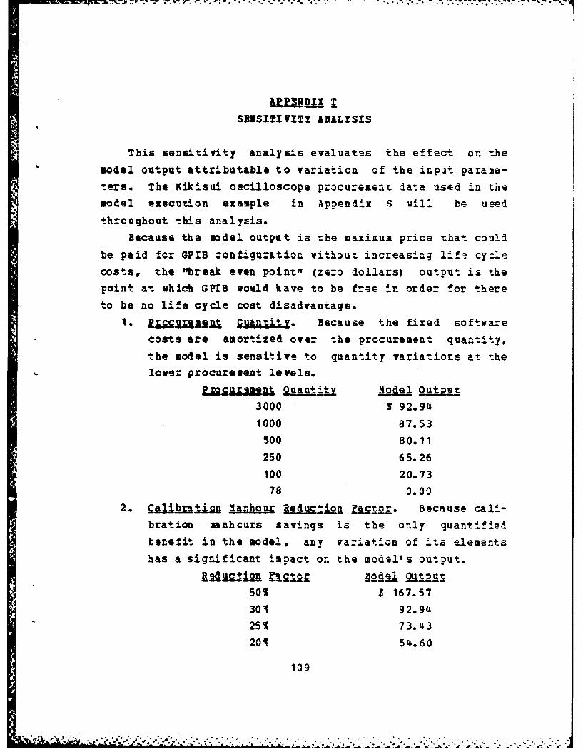
SEISITIVITY kNALYSIS
This sensitivity analysis evaluates the effect on themodel output attributable to variation of the input parame-ters. The Kikisui oscilloscope procu-ement data used in themodel execution example in Appendix .5 will be used
thrcughout this analysis.
Because the model output is -he maximum price that could
be paid fcr GPIB configuration without increasing lira cyclecosts, the "break even point" (zero dollars) output is thepoint at which GPIB wculd have to be free in order for thereto be no life cycle cost disadvantage.
1. LIMOaN= guan1j11, Because the fixed softwarecosts are amortized over the procurement quantity,
the model is sensitive to quantity variations at thelewer procurement levels.
- i33sZn Quantty M tput3000 S 92.941000 87.53
500 80.11
250 65.26
100 20.73
78 0.00
2. .lib M Reduction Factor. Because cali-bration manhcurs savings is the only quantified
benefit in the model, any varia.tion of its elementshas a significant impact on the model's outpu.
jL21=LMQA2 E! =-JC od50% $ 167.57
301 92.94
25% 73.43
20% 54.60
109
r _, o,,, . .,.;.-, ,,-.;..-.,-. ... ..-. *''-. . . --'.- • . --. - . . -. " . " .-. - .• - -.
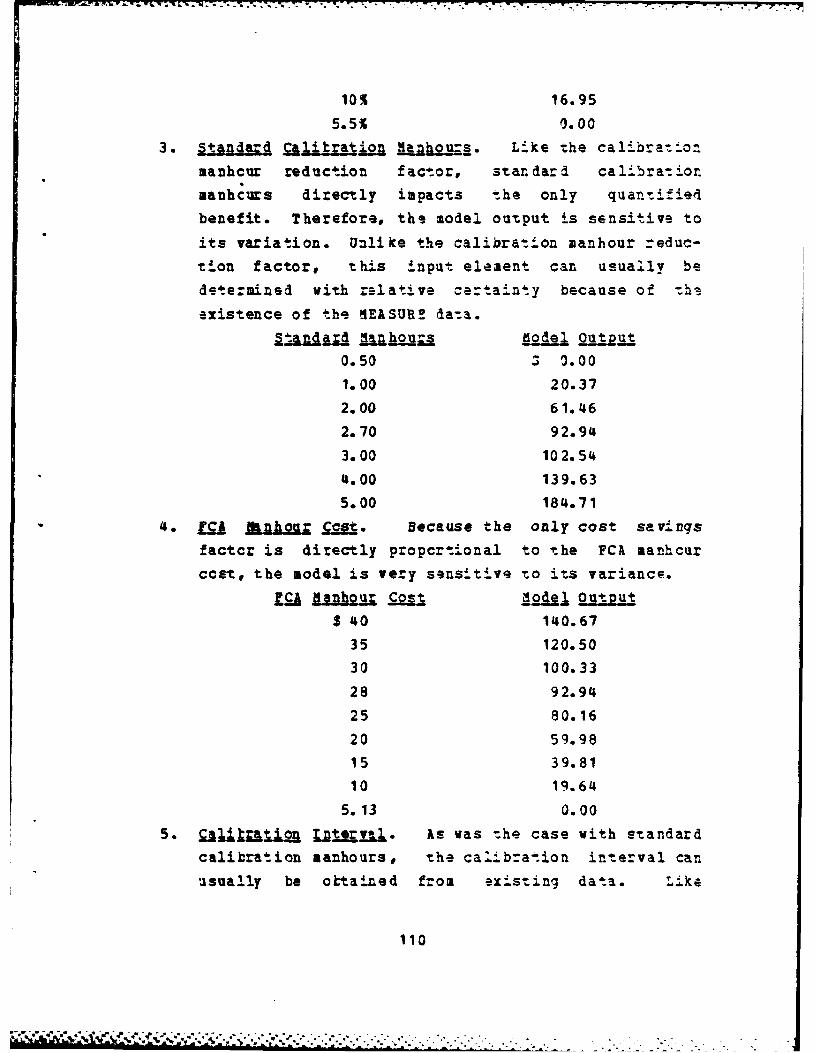
10% 16.95
5.5% 0.003. Standard Qlitration _ O-S. Like he calibra:_on
manhcur reduction factor, standard calibrat ionmanhcurs directly impacts the only quantifiet4
benefit. Therefore, the model output is sensitive to
its variation. Unlike the calibration manhour reduc-
tion factor, this input element can usually be
determined with ralative certainty because of -hs
existence of the nEASUR! da-a.
0.50 5 0.00
1.00 20.37
2.00 61.46
2.70 92.94
3.00 102.54
4.00 139.63
5.00 184.71
'4. M a U Q . Because the only cost savings
factcr is directly propcrtional to -.he FCA manhcur
cost, the model is very sensitive to its variance.
m anhour Cost Ll~de]; OutputS 40 140.67
35 120.50
30 100.33
28 92.94
25 80.16
20 59.98
15 39.81
10 19.64
5.13 0.00
5. Qjjr Zot+.er!-_. As was the case with standard
calibration manhours, the calibrat-ion interval can
usually be oktained from existing data. Like
110
. .- S - /... ; .*. . -. . ---..--.. ., , "-. . .
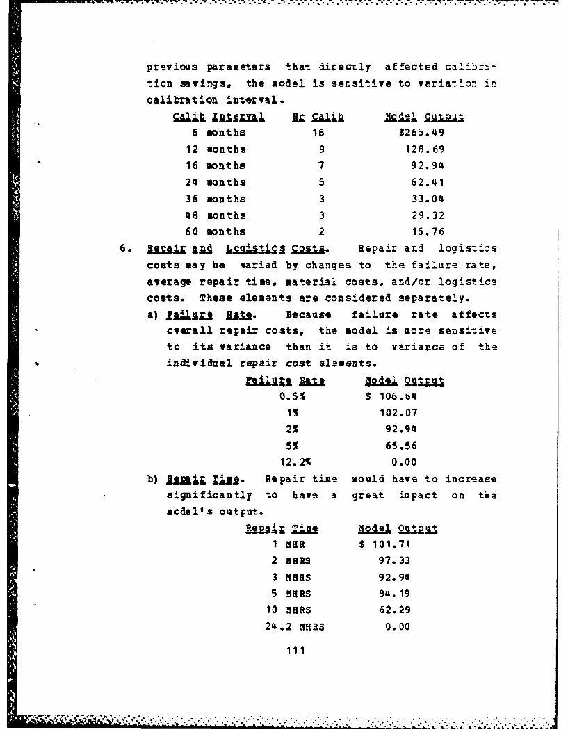
previous parameters that directly affected calib.a-
tion savings, the model is sersitive to variation in
calibration interval.
6 months 18 $265.49
12 months 9 128.6916 months 7 92.94
24 months 5 62.41
36 months 3 33.04
48 months 3 29.32
60 months 2 16.76
6. r jj l o £.ss. Repair and logist-ics
costs may be varied by changes to the failure rate,
average repair time, material costs, and/or logistics
costs. These elements are considered separately.
a) fa.l112 Rjj. Because failure rate affectsoverall repair costs, the model is more sensi.ivetc its variance than it is to variance of the
individual repair cost elements.
.lu Rate Model ouTut
0.5% $ 106.64
1% 102.07
2% 92.94
5% 65.56
12.2% 0.00
b) I rL~ Uj-2 Repair time would have to increase
significantly to have a great impact on the
mcel' s output.
____ 2ae Mdel 2=~24
1 MHR S 101.71
2 MiRS 97.33
3 NHRS 92.94
5 MHBS 84.19
10 MHRS 62.29
211.2 HRS 0.00
111
.................... ", "" .......... ......................... '
. . • ~, , • . • , . . ... • • . .. . . * *o. - .. . . . . .
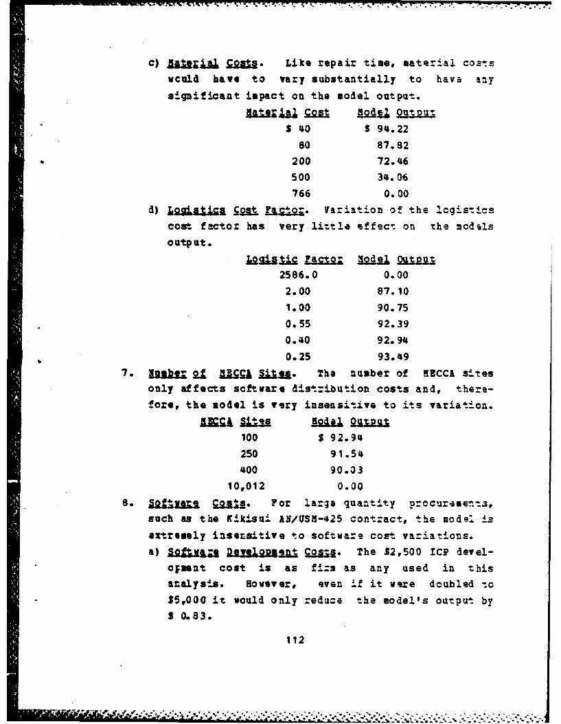
c) l j xial Cost.- Like repair time, material cos-swculd have to vary substantially to havw any
significant impact on the model output.
ljilgrs" q= Agodjj 2auinitS 40 S 94.22
80 87.82
200 72.46
500 34.06
766 0.00
d) JjAtI Qp f& I friation of the legisticscost- factor has very little effect on the mcdls
output.
j~j i Factor §gdJ 1 2utout2586.0 0.00
2.00 87.10
1.00 90.75
0.55 92.39
0.40 92.94
0.25 93.49
7. =&j g. EJ iu. The number of MECC& si-tes
only affects software d ist:ibu tion costs and, there-fore, the model is very insensit.ive to its variation.
100 $ 92.94
250 91.54
400 90.03
10,012 0.00
8. 22 M 92j112 For large quantity procurements,such as the K9.kisu± AI/USIH-,425 contract, the mod . is
extremely insensitive to software cost variations.a) So .-a DevyoV OG=..S The $2,500 ICP devel-
o;snt cost is as fi'zm as any used in thisanalysis. However, even if it were doubled -to
$5,000 it would only reduce the model's output by
3 0.83.
112
' " ,r Wn r / . . *::,, , ,;.- .....- . ........... .-.-.... *.. .,,' ... ... .....-. ..... --.. ..-
b) Igml fljaifeljfl qogtl. Doubling the ann~um!ICP maintenance cost to $600 per year would onlydecrease the model's output by $ 0.70.
C) ]a.-' D % 2 i Qtc ._ Doubling the annualZCP distribution costs ta $800 per year would only
decrease the model's output by 3 0.94.
113
m m m mm + ' ' * * " ' .-" " * " ,- " . . .'' "+ " ',T'&' - L+' * .I - ' " ". '

- AVAILABILITY BDOCTIONS DUE TO ISSE-488 INSTILLATION
This study only considers use of the IE.E-488 interfacebus fcr calibration purposes, therefore, only bus failures
that impact calibrat.icn accomplishment w .l adversely affect
instrument availability. Because a functicnal in--erface busis net requir-ed for the test instrumant's functional use,the instrument could be calibrated using bas independent
(HECCA open loop cr conventional manual) methods and
returned for use. Therefore, the only bus failure that
would preclude any form of calibration would be one vhichwould cause instrument inoperability in bcth the local and
remote modes (a "hang up").
Tc ascertain the probability of such a "hang up" anumber of individuals experienced in IBEE-488 bus operation
and maintenance were surveyed. The results of this surveyfollews:
Er. Richard Calhoun Definite possibilityEEC Pomona
Phonecon of 29 Nov 1983fir. Micheal Fcley "Highly Improbable"
KARP Pensacola Type IIPhcnscon of 21 Jan 83
Mr. Paul Willenborg Has heard of one such
NAIC Patuxent River incidence
Visit of 24 Feb 83
Mr. Rcbert Rawson Does not believe that itJohn lake Corp. is possible.
Phcnacon cf 29 Nov 1982
114

7 _ . V 77
fir. Bobert Holcomk "Highly improbable"
SAX YCL Tustin
phonecon of 13 Jan 1983
Mr. Craig Gaby Bus failure ve.y seldom
Bvlett-Packard Service affects local cperation.Canter, Atlanta
phcnecon of 18 Jan 1983The findings of this survey were presnted to the AC/D
Conference in Dallas, Texas on 30 Sarch 1983 (see Appendix G
for a list of attandees). The coasensus opinion of the
conference attendees was that the possibility of such a
.alfuact.cn is remote.
115
.115. . . .

1111-488 SUBSET REQUIRENBTS FOR AUTOMATED CALIBRATION
The following IE.-488 automated calibration subset
requirements represent the identical inputs of Mr. Edward
Greer* Naval Air Test Center Code IS-243, and Mr. Richard
Calhoun, Metrology Engineering Center:
Source Handshake SH SHO not allowed
Acceptor Handshake AH kHO not allowed
Talker cr Extended T or TE TOT3,T4,T7,T8 not
Talker allowed
TEOTE3,TE4,TE7,TE8 not
allowed
r1.T2,T5,T6 preferred
TEITE2,T5,TE6 preferred
Listener or L or L3 LO not allowed
Extended Listener LEO no: allowedService Request SR SRI required
Remote Local RL RLO not allowed
BLi preferred
RL2 not preferred
Parallel Poll PP PP1, PP2 optional
Device Clear DC DCi requiredDevice Trigger DT optional
116
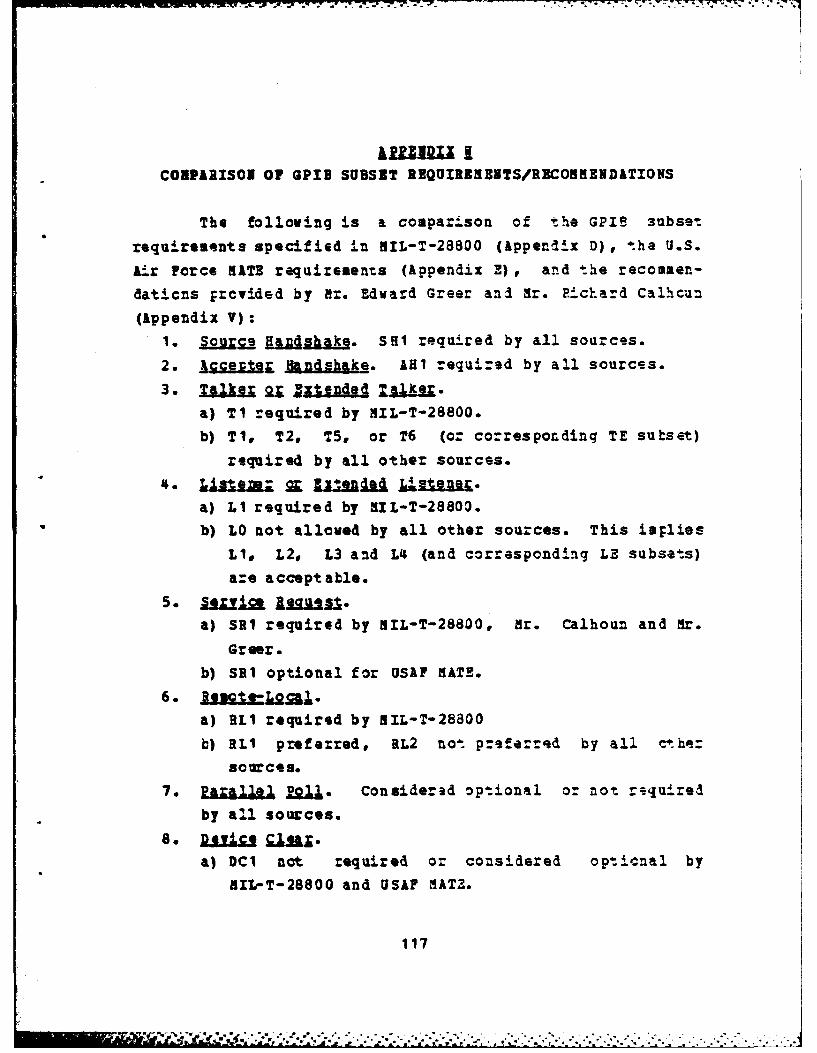
COBPARISON Of GPID SUBSET REQUIREMEBTS/RECONMENDATIONS
The folloving is a comparison of the GPIB 3ubset
requirements specified in MIL-T-28800 (Appendix D) , the U.S.
Air Force KATE requirements (Appendix E), and the recommen-
daticns Ercvided by Nx. Edward Greer ani Mr. Richard Calhcun
(Appendix V):
1. SuSe I_.Dhaki. SHI required by all sources.
2. Accept Handshake. AHI required by all sources.
a) Ti required by NIL-T-28800.
b) TI, T2, TS, or T6 (or corresponding TE subset)
required by all other sources.
a) LI required by NIL-T-28803.
b) LO not alloed by all other sources. This implies
LI, L2, L3 and L4 (and corresponding LE subsets)
are accept able.
a) SRI required by MIL-T-28800, Mr. Calhoun and Mr.
Greer.
b) SRI optional for USAF KATE.6. 3eNgte alJ.%
a) RLI required by NIL-T-28800
b) RLi preferred, RL2 not praferred by all ct.he=
sources.
7. Parall e Considered optional or not rsquired
by all sources.
a) DC1 not required or considered opticnal by
MIL-T-28800 and USAF MATZ.
117

b) DCI required by Mr. Calhoun and Mr. Greer._: 9. .,.Ua..g 2::qU-
a) DTI not required or considered opticrnal by
•IL-T-28800 and USAF HATE.
b) DTI required by Mr. Calhoun and Mr. Greer.
!
118
llm IIIIII nl null m m mnn * n.l~all -I I ... . *t..,, ..... w h' ' " : •
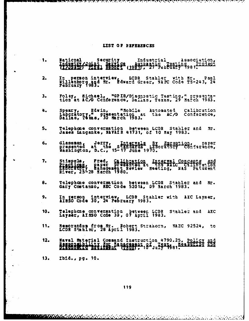
LIST O1 PBFEREICES
1. Naticnal Secur4-Y Industzial Association,.51111f~n .4at'' ect
ULU Ol' ZHl T-(19 P eb!_.y /: o1.
2. In person interview, LCDR Stahler vi#h dr. Paul" illenbor and Mr. Edward Greer, HATC Code TS-243, 24February 1913.!
3. Folsy, Michael, "GPIB/Diagnostic Tasin g," pr~s.nta-ticn at AC/D Ccnference, Dalas, Texas, 29 march 1983.
4. Speary, Edwin, "Mobile Automated CalibrationLabcratoryl, presentation at the AC/D Conference,Dallas, T as, 30 March 1983.
5. Telephone conversation between LCDR Stahler and Mr.James Langanke, NAVIIR 41731, of 10 May 1983.
6. Glassman Jerry, ion, paper_ p~resents&d at the Stan'-f '-ds- La-ora-ory -on-.9_ rence,.ou D.C., 15-17 June 1970.
7. StiFe1ple, F red, a Concepts andji.i s, aper presented at LC:at-.on
avcra~ory aanagement Review Meeting, NAS PatuxentRiver, 25-28 March 1980.
8. Telephone conversation between LCDR Stabler and Mr.Gary Costanzo, EC Code 5201k, 09 arch 1983.
9. Inerson interview LCDR Stabler with AXC Layser,AISO Code 30, 24 February 1983.
10. Telephcne conversation between LCDR Stahle: and AXCLayser, £I550 Ccde 30, 07 Apr.il 1983.
11. Memorandum from Mr. Robert St-aho.n, 1AZC 92524, toLCDR Stahl-sr, 28 April 1983.
12. Naval Material Command Instruction 4790.25, an4
13. Ibid., pg. 10.
119
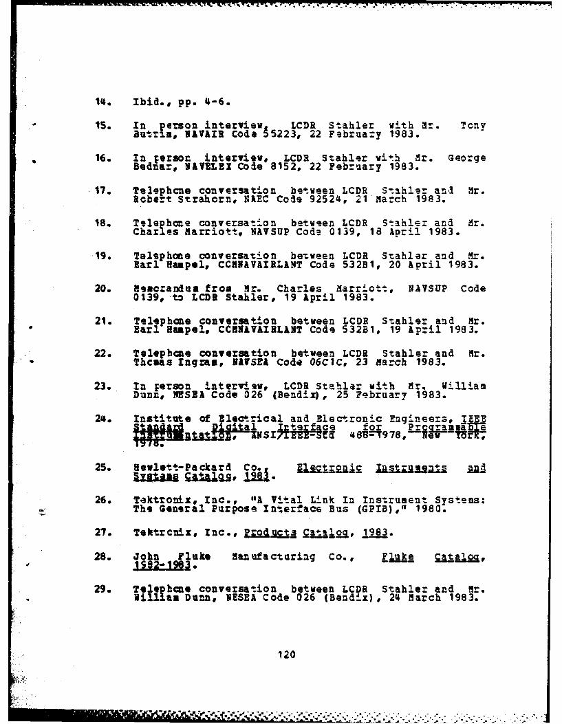
14. Ibid., pp. 4-6.
15. In person interview LCDR Stahler with Mr. TonyButr I, NIlVIR Code 55223, 22 February 1983.
16. In Ferson interview, LCDR Stahler wih Mr. GeorgeBednar, N&VELEIX Code 8152, 22 February 1983.
17. Telephcne conversation between LCDR S-.ahler an.d Mr.Robert Strahorn, NAEC Cole 92524, 21Ma.ch 1983.
18. Telephone conversation between LCDR Stahier and Mr.Char es arriott NAVSUP Code 0139, 18 April 1983.
19. Telephone conversation between LCDR Stahler and Mr.Earl Haapl, CCKNAV&IRLANT Code 532B1, 20 April 1983.
20. Memorandum from Mr. Charles arriott, NAVSUP Code0139, to LCDR Stahler, 19 April 1983.
21. Telephone conversation between LCDR Stahler and Mr.Earl Hfapelt CCHN&V&IRLANT Code 532BI, 19 Apr.l 1983.
22. Telephone conversation between LCDR Stahler and Mr.Thcas ingram, NAUSEA Code 06CIC, 23 March 1983.
23. In Ferson interview, LCDR Stahlar with Mr. WilliamDunne NESER Code 026 (Bendix|, 25 February 1983.
2 . Institute of Electrical and Electronic Engineers, IEEEStandard & l nefa for Prilra am nWl-11S~t,, 81;--9 78, ?a
25. Hfewlett-Packard Co a.e%,loq. s s a d.,.,,,.
26. Tektronix, Inc., "A Vital Link In Instrument Systems:The General Purpose Interface Bus (GPIB)," 1980.
27. Tektrcnix, Inca, P . _c j. 1983.
28. John Fluke sanufacturing Co., Lluk. _Ql K,
29. Telib ne conversation between LCDR Stahler and Mr.Will as Dunne, NESEA Code 026 (Bendix), 24 March 1983.
120

30. Tektronix Inc. "IEEE-488 Instrumentation Designedfor Easy System Development," 1982.
31. Tektronix, Inc., "Taktronix Codes and Formats for GPIBInstruments," 1981.
32. Telephone conversation between LCDR Stahle: and CAPT.Allen, USAF KATE Office, Code ASD/AEGB, of 09 March1983.
33. Telephcne conversation betweaen LCDR Stahler and .1r.Harry Davis, Kelly AFB, Code SA/ALC-3MTM, 16 Feoruary1983.
34. Telephone conversation between LCDR Stahler and Mr.Richard Pribyl U S. Army Comaunications-ElectronicsCommand (CECOMf, Code PM-TMOD, Fort Monmonth, N.J., 24January 1983.
35. Telephone conversation between LCDR Stahler and r.Ralph Compton, NAVELEX Code 8151, 11 Ap-il 1983.
36. Telephone conversation between LCDR Stahler and Mr.George Bednar, NAVEIE Code 8152, 13 April 1983.
37. Telephone conversation between LCDR Stahler and Mr.Tony Butrim, NAVUIR Code 55223, 11 April 1983.
38. Telephone conversation between LCDR Stahler and Mr.Thcmas Ingram, NAVSEA Code 06CIC, 11 April 1983.
39. Telephone conversation between LCDR Stahler and Mr.Adam Stiel, NEC Code 50CM, 30 November 1982.
40. John Fluke manufacturing Co., "7405A AutomatedCalibration System," 1980.
41. Telephcne conversation between LCDR Stahlar and Mr.Jerry Hayes, MEC Code 50, 10 February 1983.
42, Telephone conversation between LCDR Stahler and Mr.Adam Stiel, NEC Code 50CM, 27 January 1983.
43. Telephone conversation between LCDR Stahler and Mr.Richard Calhoun, MEC Code 5301, 29 November 1983.
44. Telepbone conversation between LCDR S-ahler and Mr.Richard Calhoun, 3EC Code 5301, 01 April 1983.
121

45. Tlephcne conversation between LCDR Stahler and Mr.Paul Willenborg, NATC Code TS-243, 24 November 1982.
46. Telephone conversation between LCDR Stahlar and Mr.Edward Greer, NATC Code TS-243, 06 April 1983.
47. Telephone conversation between LCDR S.ahlr and M.Fat LCos, NWS Concord. Weapons Quality EngineeringDivisicn, Code 373, 12 april 1983.
48. Telephone conversation between LCDR S.ahle_ and Mr.Jerry Glassman, NEC, 04 May 1983.
49. Riebe, Harry "Nodular/Stzuctured Programming,"presentation at AC/D Conference, Dallas, Texas, 29garch 1983.
50. Telephone conversat.ion between LCDR Stahler and Mr.Juan Moore, Tektronix, Inc., 28 February 1983.
51. In person interviev, LCDR Stahler with Mr. RalphCompton, NAYELEX Code 8151, 22 Fabruary 1983.
*52. Department of Defense, Ar 34 Forces Prcrmn.itgl...2n, para. 3-213, 01 July 19=E
53. Telephone conversation between LCDR Stahler and Mr.Joseph Siedlecki, WAVELEX Code 08T2, 06 April 1903.
54. naval Material Command Inszruction 5430.521,_qugi i at 0a n ,q me4at of iectrnic Tes
55. Tilden, Mark and Raaire , Bob, "Understanding IEEE-488Basics Simplifies System Insgration," Tektronix Corp.reprint from aj, 09 June 1982.
56. Wainschel Engineering Co., I.c., Shor. . Forjj Q=qg
57. T elephone conversation betveen LCDR Stah er and Mr.Julu$ s:aer, Hewlett-Packard Reliability EngineeringDivision, Stanford Park, CA., 25 April 1983.
58. Telephone conversa ion between LC3R Stahler and 3r.Jack Stoll, Tektronix Envi-onmental Testing Division,Beaverton, OR., 28 April 1983.
122
in -,. : ,i.,.. :v ...... , .: - . .; . .f .t ft . t ,. .t .t . .t .. . . . .
59. Telaphce converfation between LCDR S-ahler a.d Mr.Gene Baisch, Hew ett-Packa-d Parts Iden-'i.±cat.in, 1April 1983.
60. Telephcne conversation between LCDR St.ahl.r and Mr.Edward Greer, NATC Code TS-243, 12 April 1983.
61. H-lett-Packard Co., "PT01 Instrument Iaintenanc sServices and Prices" (microfi he), 01 November 1982.
62. Tektronix Inc., "Pirm Prics Service Schsdule," 03April 1983.
63. In person interview, LCDR Stabler with CDR Pe-e- W.Blondin, NPS, 28 April 1983.
64. Department of the Navy, Office of the Comptroller,
zuvx & Han"I Lg, NAVSO P-1000, para. 035750.
65. Ibid., pg. 5-96.
66. Telephone conversation between LCDR Stahler and Mr.Robert Leach, AIRSO Code 30, 24 March 1983.
67. Nicholson, Walter 4 Iutermedia ic-oeconomics and Its
68. Zinlermn, Denise C., Ecoami Analysis Procu~-s for68 kDP, Nava 1.Data Automato n m-imiri W-shU-.n ,D.-Paz7,
U 15 7000. March 1980.
69. Metroloqy Engineering Center, MeijoloU _ljuirents"?a, NAV&IR 17-35,1TL-1, October-T9 7.a
70. Hewlett-Packard Co.,"Instrument Repair Center Servicesand Prices," 01 November 1982.
71. Telephone conversation between LCDR Stahle. andTektronix Service Department, Santa Clara, CA., 28April 1982.
123
-,, ,' " ,'. ... '. : .'. . .: '.'.',':,. ., ., .. .. ., . ...."..,-.,... .. . .. . . .. . ...... .. .,-..- . . ... •... ... . . .., .' .". ,. ... .
-s a.---. 77-7-7 --_' 94. W*. --- "-17....-*
INITIIL DISTRIBUTION LIST
Nc. Copies
* 1. Defense Technical Information Center 2.c~ero $ta tign. ...ifezeania, Virginia 22314
2. Library, code 0142 2Naval Postgraduate SchoolMcntersy California 93940
3. CDRJohn Hall 3AIR-417Naval Air Systems Command Hq.washington, D.C. 20361
'4. Prafesr J.. Creighton INaval Pcst raduate SchoolMonterey, 9a 93940
5. Di flias D. Stabler 208 sbrg Court
Virgin a Beach, VA. 23464
6. Naval Air Systems Command 1Ccde 552Vashington, D.C. 20361
7. Mal Electronic Systems command 3
Washington, D.C. 20361
8. Hr& 2hpas Ingram 1Coa., 06CLC
Naval Sea Systems COmmandVashington, D.C. 20362
9. Commander, aval Air Force, 1U9s IlantIc FleetNaval Air StationIorfolk, VA 23511
10. Coumande; Naval Air Force, 1U.S. Pacific FleetCc;d 74VAS North IslandSan Diego, CA 92135
11. Command r, SurfaLce Force, IU.S. Atlant c FleetATTN: LCDR John Beynolds~Code 442
Norfolk, VA 23511
12. H a9vflrFitzgerald 1
Naval Aviation Logistics CenteZNaval Air StatiovPatuzent River, MD. 20670
124
II i iI ' iff , ,,,++ % % -, . .,; .-- +.. -. .jr. -. ,,".+-,s-- . -..9 . * .. '-. ,s.''. 9- ",,9, "99. '-9" " *9." .*'. ."- - " " " . . ."
13..,Nr Jerry Hays 2;merclogy lngneer ng Centar-Naval Veapons Station, Seal Beach,PcmcDa AnnexP.O. Box 2436,Pcmona, CA. 91769
14. Mr Donald Tqbey..S once AppAcat .ns. Inc.1150 River Bend CriveSuite 100Dallas, Texas 75247
15. _rt 111e Hollinger 1mailStop 40Naval 2ilctronics systems Engineering c-ivitvSt. Inigoes, MD 20684
16. 1. iaul Willenbcz1eVal A r Test CenterCede IS-243Naval Air StationPatuxent Rivere, D. 20670
17. 51 Cliff Oehluann
Gullanve and ifetrology Centera.S. Air Porce BaseNevark, 06. 43055
18. 5:. Thomas Leed 1Zetrols te s Divis ion
Nati na Bureau cf Standardsashington, D.C. 20234
19. Comame di Officerlv9al le ons Support Center
BCod 70721Att n: %r..iarry ScllmanCrate, Indiana 47522
20. fir Ri~rd AndersonNaval Aviation Lcgisticu CenterDetachment lestNIS Uorth Isla4San Diego. CA 11135
21. r.VeronNarsh
Naval Aviation Logistics CenterDetacheent EastNaval A.Lr StationNcrfolk, VA. 23511
22. Aircraf t ntermedia:e maintenance- Sagpoit ce (AIRSO)
ccu a 0
Naval Air StationPatuxent River, 1D 20670
125
+, ,,,.+r .% ,,* ,.-,,.+ ,- .,,,..?,?...+.,,? . +? .; ... .,.... .?+ ? ... ./ .+..,.-.++ .+ .:. .-? ..

.PI