PURCHASE SPECIFICATION; GROUP: PHOTOVOLTAICS PS-439 … · 160 sq.ft along with chemical toilet,...
31
PURCHASE SPECIFICATION; GROUP: PHOTOVOLTAICS SUPPLY OF BOS ITEMS AND I&C FOR 2.5MWP SPV POWER PLANT AT BHEL-JHANSI, U.P PS-439-1174 Rev No: 00 PAGE : 1 OF 27 PV SYSTEM ENGG Technical Specification for Supply of Balance of System items and Installation & Commissioning For 2.5 MW Solar PV grid connected power plant at BHEL-Jhansi, UTTAR PRADESH Revision details : Prepared: LNK / VCP Approved: VKS Dat e: 23.11.2017 COPY RIGHT AND CONFIDENTIAL The information on this document is the property of Bharat Heavy Electricals Limited. It must not be used directly or indirectly in anyway detrimental to the interest to the company
Transcript of PURCHASE SPECIFICATION; GROUP: PHOTOVOLTAICS PS-439 … · 160 sq.ft along with chemical toilet,...

PURCHASE SPECIFICATION; GROUP: PHOTOVOLTAICS
SUPPLY OF BOS ITEMS AND I&C FOR 2.5MWP SPV POWER
PLANT AT BHEL-JHANSI, U.P
PS-439-1174
Rev No: 00
PAGE : 1 OF 27
PV SYSTEM ENGG
Technical Specification for
Supply of Balance of System items and Installation & Commissioning
For 2.5 MW Solar PV grid connected power plant at
BHEL-Jhansi, UTTAR PRADESH
Revision details :
Prepared:
LNK / VCP
Approved:
VKS
Date:
23.11.2017
COPY RIGHT AND CONFIDENTIAL
The information on this document is the property of Bharat Heavy Electricals Limited.
It must not be used directly or indirectly in anyway detrimental to the interest to the company

PURCHASE SPECIFICATION; GROUP: PHOTOVOLTAICS
SUPPLY OF BOS ITEMS AND I&C FOR 2.5MWP SPV POWER
PLANT AT BHEL-JHANSI, U.P
PS-439-1174
Rev No: 00
PAGE : 2 OF 27
PV SYSTEM ENGG
1.0 Introduction
Bharat Heavy Electr icals Limited (BHEL), Electronics Division, Bangalore is setting up a 2.5 MW Gr id
Connected SPV Power Plant for BHEL-Jhansi, Uttarpradesh.
The plant w ill have PV modules of mono-crystalline / poly-crystalline type mounted on module
mounting structures. Electr ically, the PV array w il l have 2 near ly equal segments, each generat ing DC
power of ~ 1250kWp, which is then inverted to AC by gr id-connected power condit ioning units (PCU)
of 1250KW rat ing. At the AC output level, every two PCUs are combined using a 3-winding dry type
transformer of 2.7 MVA rat ing which w ill step up the voltage to 11KV.
The solar ar ray w ill have 18 str ing monitor ing combiner boxes (SMBs) that collect the solar PV
generated DC power and provide inputs to the 2 PCUs housed in centralized control room. Control
room building w ill also house HT switchgear panel, ACDB, SCADA, battery bank, FCBC, UPS and other
associated panels along with store room and toilets.
There w ill be 1 No. dry type transformers (2700KVA, 11KV/ 350-350V) located in control room. A
typical layout of control room is enclosed. The plant w ill have SCADA integration and PC based
monitor ing desk to gather DC, AC and other parameters from SMBs, PCUs, weather monitor ing
equipment, transformers, LT / HT breaker panels.
The output of solar power plant shall be connected to 11KV substat ion through 11KV underground
cable which w ill be in the scope of BHEL.
This technical specificat ion provides requirements of BHEL for supply, installat ion, commissioning of
balance of system items and defect liabili ty per iod of 6 months. BHEL scope of supply and work is
mentioned under sect ion 4.2.
Note:
Vendor shall visit the site to assess all the technical and operat ional requirements and familiar ize w ith
the site condit ions before placing the bid.
2.0 Documents enclosed with this specification
1 Tentat ive Single line diagram of overall power plant
2 Tentat ive Site layout w ith locat ions of solar ar ray, control room (Autocad drawing of
site layout w ill be provided on request by vendor through e-mail)
3 Tentat ive Control Room Layout
4 Tentat ive drawing of Str ing Monitor ing box
3.0 Documents to be submitted along with offer
1. Clause-wise compliance shall be fi l led-up in the column provided in this specification, w ith
signature and seal on every page.
2. Company brochure.
3. Project implementat ion t ime schedule.
4. Stage-wise manpower schedule.
Note: Wherever approved vendors are provided, in case if i t is required to propose addit ional vendors,
the same shall be done with pr ior approval by BHEL. For all the items wherever approved vendors are
not provided, approval of makes shall be obtained from BHEL before placement of P.O on sub-vendors.

PURCHASE SPECIFICATION; GROUP: PHOTOVOLTAICS
SUPPLY OF BOS ITEMS AND I&C FOR 2.5MWP SPV POWER
PLANT AT BHEL-JHANSI, U.P
PS-439-1174
Rev No: 00
PAGE : 3 OF 27
PV SYSTEM ENGG
4.0 Scope of Supply and work
4.1 Vendor scope of supply and work
The table below indicates the vendor ’s scope of supply, installat ion and defect liabili ty per iod of 6
months as br iefly out lined. Quantit ies mentioned below are indicat ive only. Vendor shall est imate
exact requirement and quote accordingly.
S.No Item descr ipt ion Qty Unit
1 Cable t ies 1 Set
2 SMB mounting structure & hardware 18 Set
3 MC4 connectors 415 Set
4 HDPE DWC pipe 63 mm 1000 M
5 240 sqmm Cable lugs w ith bimetallic washers and hardware in SMB 36 Set
6 Cable trays inside CR 80 M
7 Cable tray suppor t structure inside CR 1 ST
8 Cable glands 240 sqmm in PCU DC side 36 Nos
9 240 sqmm Cable lugs w ith bimetallic washers and hardware in PCU DC side 36 Set
10 1.1KV, 1CX300 sq.mm, Aluminium Conductor , XLPE insulated, Armored, PVC
sheathed Cable fr om PCU to transformer 1000 M
11 300 sqmm Cable glands for PCU AC side transformer LT side 84 Nos
12 300 sqmm Cable lugs w ith bimetallic washers and hardware for PCU AC side
transformer LT side 84 Set
13 HT cable - 11KV(UE), 3CX240 sq.mm 30 M
14 Reverse power relay 1 No
15 HT terminat ion kits - indoor 2 ST
16 ACDB 1 No
17 UPS-5 KVA with battery w ith UPSDB 1 No
18 Weather Monitor ing System 1 ST
19 DWC pipe for RS485 cable 1 ST
20 Auxiliary, data and control cables 1 ST
21 Lugs & hardware for data, auxi liary and control cables 1 ST
22 25X3 GI flat for ear thing 1 ST
23 25X6 GI flat for ear thing 1 ST
24 Ear thing electrodes for MMS 1 ST
25 Hardware for ar ray ear thing 1 ST
26 SMB ear thing electrodes 18 Nos
27 Copper cable -16 sqmm for ear thing 1 ST
28 Copper cable -2.5 sqmm for ear thing 1 ST
29 Copper flat- 50X4 for ear thing 1 ST
30 Copper cable -25 sqmm for ear thing 1 ST
31 Copper cable -70 sqmm for ear thing 1 ST
32 Ear thing electrodes for control room equipment 1 ST
33 ESE LA and ear thing 1 ST
34 Yard light ing system 1 ST
35 Module cleaning system 1 ST

PURCHASE SPECIFICATION; GROUP: PHOTOVOLTAICS
SUPPLY OF BOS ITEMS AND I&C FOR 2.5MWP SPV POWER
PLANT AT BHEL-JHANSI, U.P
PS-439-1174
Rev No: 00
PAGE : 4 OF 27
PV SYSTEM ENGG
36 Identificat ion tags, markers etc. 1 ST
37 Hoarding board 1 ST
38 Display boards and sign boards 1 ST
39 Electr ical insulat ion mat 1 ST
40 Checkered plate 1 ST
41 Air condit ioner 1 ST
42 Tool kits and instruments 1 ST
43 Office furniture 1 ST
44 Fire alarm system 1 ST
45 safety related items 1 ST
46 Spares 1 ST
47 Installat ion & Commissioning as per respect ive clauses in specificat ion 1 AU
4.2 BHEL scope of supply and work
For the sake of clar ity to the vendor , the items that are w ithin the scope of BHEL supply are listed
below.
# BHEL Scope of supply Qty
1 Supply of Solar PV Modules ~ 8300 Nos
2 Supply and Erect ion of Solar ar ray structures w ith modules mounted on
structures (MMS), w ith each having 20 Nos. of PV modules
~ 415 sets
3 Supply of Cable, 1Cx 6 sq-mm (for connect ion of PV modules to str ing
monitor ing boxes)
~ 35 km
4 Supply of Cable, 1.1KV, 2C x 240sq-mm (for connect ion from SMBs up to PCUs
and PCUs to transformers)
~ 4 km
5 Supply of Str ing monitor ing boxes (24-in, 1-out) 18 Nos
6 Supply of Power condit ioning units (PCUs) of 1250 kW rat ing along with duct 2 Nos
7 Supply of Dry type transformer 2700kVA, 11KV/ 350V-350V (1 HV winding, 2
LV windings)
1 Nos
10 Supply of 11KV indoor HT panel 1 set
11 Supply of SCADA system with PC, accessor ies and software 1 set
12 Supply of RS-485 cable and Ethernet LAN cable for SCADA 1 set
BHEL Scope of work
13 Construct ion of control room including par t it ions for SCADA, store and toilets 1 No
14 Construct ion of boundary wall for the ent ire plant, pathways, approach road,
drains w ithin the solar plant
1 set
Note: For all civil related activities in the scope vendor, quality documents (Material test
reports, Design mix report etc.) shall be submitted by vendor as per Annexure-C of BHEL
tender.

PURCHASE SPECIFICATION; GROUP: PHOTOVOLTAICS
SUPPLY OF BOS ITEMS AND I&C FOR 2.5MWP SPV POWER
PLANT AT BHEL-JHANSI, U.P
PS-439-1174
Rev No: 00
PAGE : 5 OF 27
PV SYSTEM ENGG
5.0 Detailed technical specification for supply, installation and commissioning
Vendor shall indicate clause-wise compliance (Yes/ No) in the column provided below. In case of non-
compliance or deviat ion, vendors shall record their comment.
# BHEL specification
Ve
nd
or
co
mp
lia
nc
e (
Ye
s /
No
)
In c
ase
of
no
n-c
om
pli
an
ce
or
de
via
tio
n, v
en
do
rs s
ha
ll
rec
ord
th
eir
co
mm
en
ts:
5.1 Setting up of temporary site office
(1) Vendor shall set up a temporary site office using one por ta cabin of minimum
160 sq.ft along with chemical toilet , water tank and sept ic tanks for BHEL use
within 10 days from the date of purchase order to enable speedy
commencement of site act ivities.
(2) Porta cabin shall be retained at the site unt i l complet ion of 1 month after
commissioning or t i ll complet ion of vendor ’s works whichever is later .
(3) Cabin shall be furnished with essential amenit ies such as one computer w ith
internet connect ion, printer , two work tables, six chairs and necessary number
of power points, lamps, air condit ioner and fans.
(4) Vendor shall ar range dr inking water in site office for the site engineers of BHEL
and the staff/ employees of vendor .
(5) Vendor shall make arrangement for pantry shed for preparat ion of beverages
such as Tea/ Coffee etc. Vendor shall depute office boy-cum-cook for
preparat ion of Tea/ Coffee. All the utensils, facili t ies such as LPG/ electr ic stove
and service requirements shall be included in vendor ’s scope. Consumables
such as milk, tea, coffee powder , snacks etc. shall be ar ranged by BHEL.
5.2 Electrical power and water for construction
(1) BHEL shall organize necessary electr ical power supply and water supply
required for construct ion act ivit ies in vendor ’s scope and also for the por ta
cabin on chargeable basis. Vendor shall pay the charges to BHEL based on
consumption. Necessary meter ing ar rangement shall be made by vendor .
5.3 Construction of temporary yards for safe storage of BHEL as well as vendor
supplied items except PV modules and MMS
(1) Vendor shall, at suitable locat ions at the site, as decided based on discussions
w ith BHEL site engineer , construct a temporary yard for safe storage of all
BHEL as well as vendor supplied items except PV Modules and Module
mounting structures. This includes storage of all i tems such as electr ical panels
(SMBs, PCUs, HT panels, Transformer, Distr ibut ion boards etc), cables, spares,
tools, instruments etc.
(2) Area of storage yard shall be min. 300 sq.m. However , exact size shall be
decided mutually w ith BHEL based on site condit ions.
(3) A port ion of storage yard area (min. 100 sq.m) shall be provided with suitable
temporary roof and side covers (asbestos, FRP, steel sheet etc.,) for storage of
cr it ical electr ical panels (PCUs, SMBs, HT panel, electr ical DBs etc.) in order to
ensure that there w ill not be any water spillage which may damage the

PURCHASE SPECIFICATION; GROUP: PHOTOVOLTAICS
SUPPLY OF BOS ITEMS AND I&C FOR 2.5MWP SPV POWER
PLANT AT BHEL-JHANSI, U.P
PS-439-1174
Rev No: 00
PAGE : 6 OF 27
PV SYSTEM ENGG
equipment. This should be suppor ted by steel poles that shall be grouted using
suitable concrete foundations. Height should be appropriately decided to
ensure safe operat ion of hydra for loading/ unloading etc.,
(4) Necessary raised / covered ar rangements shall be provided to the individual
panels / equipment to ensure that these items are not affected by water at the
ground level dur ing t ime of rain storm, flood etc.
(5) Yards shall be fenced all around with a steel gate of w idth of 4m minimum.
Height of fence and gate shall be 2.5m minimum above the ground level.
(6) Suitable fencing shall be provided using steel poles at every 3m intervals and
barbed wires between the poles.
(7) Gate shall be suitably secured to the fencing poles and shall be provided with
lock and key.
(8) Sufficient watch and ward secur ity personnel shall be provided for the storage
yard and complete solar plant erect ion area on round-the-clock basis.
5.4 Receipt, unloading, safe storage and movement of BHEL and vendor supplied
items except PV modules and MMS
(1) Vendor shall organize all necessary resources such as labour , machinery and
tools (cranes, hydra, forklifts, t ranspor tat ion trucks / t rolleys, li ft ing accessor ies
etc.,) for unloading the BHEL and vendor supplied items except PV Modules and
MMS received at the site and subsequent movement to the storage yard. Similar
ar rangements shall also be made by vendor for movement of the items from
storage yard to the point of construct ion for vendor ’s scope of works.
(2) Vendor shall maintain proper documentat ion / compilat ion of all the records
related to shipping (invoices, delivery challans etc.) and shall take ver ificat ion
and approval from BHEL site engineer for every consignment. The documents
shall be suitably preserved for fur ther handing over to BHEL.
(3) Safeguarding the items from pilferage etc. is responsibility of vendor . For this
purpose, vendor shall post adequate watch and ward for the yard on round-the-
clock basis.
(4) Registers shall be maintained for the yard to keep track of incoming / outgoing
items.
(5) BHEL will ensure insurance for all the items. Vendor shall provide necessary
documentat ion and assistance to BHEL for making insurance claim in case of
damage / theft of BHEL supplied items.
5.5 Interconnection of SPV modules to form strings.
Supply of SPV modules is in BHEL scope. Vendor shall interconnect the modules as
follows:
Each module is fit ted integrally w ith a junct ion box having posit ive and negative
polar ity cables (4 sq-mm).
(a) Posit ive cable of one module shall be connected to the negative cable of
adjacent module. The cables have MC4 type of connectors. One polar ity cable
has male type connector , while the other has female type connector .
(b) This way, 20 modules shall be connected in ser ies. Each set of connect ions is
called as a ser ies str ing.
(c) After placing the purchase order on vendor , BHEL will provide layout drawings
that w ill descr ibe the exact way in which the ser ies str ings are formed and
interconnected to the respect ive SMBs. Vendor shall implement the
interconnect ion as per these drawings.
(d) Interconnected cables shall be neatly routed and dressed using UV resistant
nylon cable t ies of appropr iate dimension.
(e) These cable t ies shall be in vendor scope of supply. Recommended make: 3M,

PURCHASE SPECIFICATION; GROUP: PHOTOVOLTAICS
SUPPLY OF BOS ITEMS AND I&C FOR 2.5MWP SPV POWER
PLANT AT BHEL-JHANSI, U.P
PS-439-1174
Rev No: 00
PAGE : 7 OF 27
PV SYSTEM ENGG
Phoenix contact, Weidmuller , Hellermanntyton, Panduit . BHEL approval shall
be obtained by vendor for use of any other make.
Specs: Nylon cable t ies, polyamide 6.6 UV stabilized black, UL94 flammability
rat ing V2, meant for outdoor use. Operat ing temperature up to 85 deg C. Width
of cable t ie shall be minimum 4.5 mm. BHEL approval shall be obtained for the
selected brand and length of cable t ie.
(f) Cables shall not be loosely hanging.
5.6 Installation of string monitoring boxes
(1) Supply of str ing monitor ing boxes (SMB) is in BHEL scope. These are 24-in and
1-out type.
(2) Vendor shall install the SMBs on Module mounting structure in the solar ar ray
field as per final ar ray layout.
(3) Supply of SMB mounting structures using GI channels/ angles and necessary
hardware required for installat ion of SMBs are in the scope of vendor .
(4) Drawings of SMB and the fixing ar rangement w ill be provided to the vendor
after placement of purchase order .
(5) SMB locat ion w ill be ident ified by BHEL and will be provided in the w ir ing
layout.
(6) SMBs shall be fixed on the structures using necessary hardware which shall be
supplied by vendor .
(7) All tools necessary for mounting shall be in vendor scope.
5.7 Interconnection of SPV string cables to 6 sq-mm cable
(1) Each SPV module str ing shall be connected to SMB using 1Cx 6 sq-mm cable
supplied by BHEL. Overall diameter ~ 6 mm. Diameter under the outer sheath
(i.e over the insulat ion) ~ 4.6 mm.
(2) SPV module is provided with posit ive and negative cables (4 sq-mm) having
male and female par ts of MC4 type connectors.
(3) Vendor shall supply plug connectors of MC4 type, each set having a pair of male
and female par ts, to join the 6 sq-mm cable w ith SPV module str ing. Necessary
cr imping and terminat ion is in the scope of vendor .
(4) MC4 connectors shall have rat ing of 1000VDC (IEC), rated current of 25A
(min.), Type approved by TUV Rheinland for product safety.
(5) Approved make: Mult i-contact or other reputed equivalent subject to BHEL
approval dur ing detailed engineer ing.
(6) Total quantity of MC4 connector sets required = 415 sets (each set having a
male and a female par t).
(7) Extra quantity shall also be procured consider ing possibili t ies of damages
dur ing the installat ion. Vendor shall ensure that there shall not be any shor tage
dur ing execut ion t ime.
(8) Vendor should make avai lable MC4 tool kits of quantity as required dur ing
execut ion for simultaneous working on the ar ray.
5.8 Routing of 1Cx 6 sq-mm cable:
(1) 6 sq-mm cables connect ing the SPV module str ings to SMBs shall be neatly
routed along the module mounting structures using cable t ies.
(2) Cable t ies, nylon polyamide 6.6 UV stabilized black, UL94 flammability rat ing
V2, operat ing temperature up to 85 deg C, shall be used to ar rest any possibili ty
of movement or sagging. Cable t ies shall be of make: 3M, Phoenix contact,
Weidmuller , Hellermanntyton, Panduit . Width of the cable t ies shall be a
minimum of 4.5 mm. BHEL approval shall be obtained for the selected brand
and length of cable t ie.
(3) Cables shall not be loosely hanging.

PURCHASE SPECIFICATION; GROUP: PHOTOVOLTAICS
SUPPLY OF BOS ITEMS AND I&C FOR 2.5MWP SPV POWER
PLANT AT BHEL-JHANSI, U.P
PS-439-1174
Rev No: 00
PAGE : 8 OF 27
PV SYSTEM ENGG
5.9 Underground laying of 6 sq-mm cables between the rows
(1) Where 6 sq-mm cables run between two rows of structure, HDPE double walled
corrugated (DWC) pipe shall be used to guide the cables underground from one
row to the other in trenches.
(2) HDPE DWC pipe of required length shall be w ithin scope of vendor supply.
Vendor to procure necessary quantity of HDPE pipes based on the actual
requirement and ensure no shor tfall in supply during the t ime of installat ion.
Qty required~1000 M
(3) Inner Diameter (ID) shall be selected to accommodate the number of 6 sq-mm
cables to be guided. However , Inner diameter shall be limited to a minimum of
63mm. Make: Tirupat i Plastomatics, Jaipur or reputed make, as approved by
BHEL.
(4) Make, par t number , sizes / dimensions, datasheet shall be submitted to BHEL
for approval.
(5) Details of cable trench:
(a) Trench depth = 600 mm minimum.
(b) Trench width = 200 mm minimum.
(c) Bottom layer shall be sand of IS: 383 with 100mm thick.
(d) HDPE conduit shall be laid over the sand layer .
(e) Another layer of sand of 100 mm thick.
(f) Then, a single layer of class-2 br ick (burnt clay type) of 75 mm thickness
shall be laid.
(g) Trench shall, then, be fi l led w ith refi ll soil and compacted.
5.10 Connecting the 6 sq-mm cables on input side of SMBs
(1) 6 sq-mm cables of posit ive and negative polar it ies or iginating from SPV module
str ings shall be terminated at the input side of SMBs using MC4 connectors.
(2) MC4 connectors are fitted on input side of SMBs. Matching MC4 connectors will
be supplied by BHEL in loose.
(3) Vendor scope includes removal of sleeve at the cable end, cr imping with MC4
connectors. These MC4 connectors have to be terminated on to the MC4
connectors that are par t of the SMBs supplied by BHEL.
(4) All necessary tools such as pliers, str ippers, cr imping tool etc. shall be w ithin
vendor scope.
5.11 Connecting the DC power cables on output side of SMBs
(1) Cables of size 2Cx 240 sq-mm (Aluminium, armoured, XLPE insulat ion, PVC
sheathed) shall be terminated at the output side of SMBs. Supply of this cable is
in BHEL scope.
(2) Overall diameter of cable ~ 45mm.
(3) Vendor scope includes removal of sleeve at the cable end, cr imping with
suitable cable lug of appropr iate type/ size and connect ing the lugged end to the
bus bar w ithin the SMB. Cables shall enter the SMB through the cable glands
that are supplied by BHEL along with SMBs.
(4) Aluminum Cable lug and bimetallic washer (Cu and Al) shall be in vendor scope
of supply. Vendor shall submit catalog and datasheet of lug before procurement.
Make: Dowell’s / 3D / 3M or any other reputed equivalent as shall be approved
by BHEL. Quantity required ~ 36 Nos.
(5) Hardware such as bolts, nuts, plain washers and spr ing washers shall be in
vendor scope of supply. The size and type of these shall be in accordance with
terminat ion ar rangement on the bus bar of SMB. Hardware should be SS304.
Spr ing washers should be Zn coated.
(6) All necessary tools such as pliers, str ippers, cr imping tool etc., r equired to
complete the work shall be w ithin vendor scope.

PURCHASE SPECIFICATION; GROUP: PHOTOVOLTAICS
SUPPLY OF BOS ITEMS AND I&C FOR 2.5MWP SPV POWER
PLANT AT BHEL-JHANSI, U.P
PS-439-1174
Rev No: 00
PAGE : 9 OF 27
PV SYSTEM ENGG
5.12 Cable trenches for laying power cables from SMB to inverters:
(1) 2Cx 240 sq-mm (Aluminium, armoured, XLPE insulat ion, PVC sheath) cables of
positive and negative polar it ies are routed from SMB box to power condit ioning
units (PCUs) located at control room.
(2) These cables shall be laid underground from the point near SMB to control
room.
(3) One cable (+, -) from each of the SMBs have to be routed to respect ive inver ters.
(4) Tentat ive Array layout w ith locat ion of SMBs and control room is enclosed for
vendor ’s reference and for est imation purpose. Exact solar ar ray layout w ill be
provided by BHEL after placing purchase order . Vendor shall prepare and
furnish cable rout ing layout as per standards for approval by BHEL.
(5) Vendor shall est imate the length of cable trench. Generally these power cables
w ill be packed in 1000 m drums. Vendor has to carefully plan laying of far ther
cables first to ensure cut lengths can be used for shor ter cables. Any shor tage of
cable occurr ing because of vendor ’s works w ill be in the scope of the vendor .
(6) Vendor shall construct the underground trench as follows:
(a) Trench depth = 750 mm minimum.
(b) Trench width shall vary en route to control room, based on the number of
cables. As the cables join from SMBs en route, bunching takes place and the
w idth of trench shall increase. Max trench width expected = 2m.
(c) Sand as per IS: 383 of 100 mm layer thickness shall be laid at the bottom
most level of trench.
(d) Over the sand layer , cables shall be laid one adjacent to the other . Cables
shall not be laid one over the other . In other words, only one layer of cables
shall be allowed.
(e) Over the layer of cables, one more layer of sand of 100mm shall be laid.
(f) Then, a single layer of class-2 br ick (burnt clay type) of 75 mm thickness
shall be laid.
(g) Trench shall then be fi l led up with refi ll soil.
(h) Subsequently, land over the cable trench shall be leveled and compacted
suitably.
The cables shall be laid inside Class-B GI pipes/ RCC hume pipes of suitable size
under road crossings, drains, sewerage lines, entry and exit points of the buildings
or where there are chances of mechanical damage Only terminal cable joints shall
be accepted. No cable joints to join two cable ends is acceptable. Supply of GI/ RCC
hume pipes is in the scope of vendor .
5.13 Installation (indoor) of PCUs with ducting, transformer, HT panels, SCADA
panel, ACDB located inside control room together with cable trays in cable
trench:
(1) Vendor shall organize necessary resources such as labour , cranes, hydra,
forklifts, t ransportat ion trucks / t rolleys and other accessor ies for movements
and posit ioning of the items as below within the control, inver ter and secur ity
rooms:
a. PCU panels: 2 sets (each ~ 2500 Kg)
b. Dry type transformer : 1No (~ 2000 Kg)
c. HT switchgear panel : 1 No (~ 1500 Kg)
d. ACDB panel: 1 No
e. SCADA panel: 1 Nos (~ 500 Kg each)
f. Control desk w ith PCs and accessor ies: 1 set
(2) All equipment shall be placed over the cable trenches in control room, in the
exact sequence and locat ions as shown in BHEL drawings that will be provided
to vendor at an appropr iate t ime dur ing the per iod of execut ion.
(3) All equipment shall be suitably grouted using welding / bolt ing methods as

PURCHASE SPECIFICATION; GROUP: PHOTOVOLTAICS
SUPPLY OF BOS ITEMS AND I&C FOR 2.5MWP SPV POWER
PLANT AT BHEL-JHANSI, U.P
PS-439-1174
Rev No: 00
PAGE : 10 OF 27
PV SYSTEM ENGG
appropr iate. BHEL approval shall be obtained for the grout ing ar rangement. All
necessary hardware for the same shall be w ithin vendor scope of supply.
(4) Vendor shall supply and install cable trays of required length and corner bends
as required within control room for laying DC, AC & signal cables over the trays.
Vendor shall supply cable trays as follows:
a. Ladder type GI cable trays
b. Hot dip galvanized
c. Depth = 40 mm min.
d. Width = 600 mm min.
(5) Vendor shall fix the cable trays on the project ing steel sect ions in cable trench
of control room. Supply and works related to the appropr iate placement of
these steel sect ions w ill be in the vendor ’s scope.
(6) Adjacent cable trays shall be interconnected using suitable hardware items that
shall be in vendor scope of supply.
(7) Cables shall be laid over the cable trays and neatly dressed using appropr iate
cable t ies etc.
(8) Cables from AC side of PCU (7RX1Cx300 sq.mm per phase) shall be laid over
ladder type cable trays up to LV side of 2700 KVA inver ter transformer located
in control room.
(9) Vendor shall install exhaust duct ing on top of PCUs (1 set for each PCU) to
throw heat from inside PCU to outside control room. Supply of duct mater ial
shall be in the scope of BHEL.
(10) All 11KV panel and transformer works shall be carr ied out by a licensed
electr ical contractor as per STATE ELECTRICITY SUPPLY & TRANSMISSION
BOARDS/ CEA regulat ions.
5.14 Power cable terminations on DC side of PCUs
(1) On DC side, for each PCU, vendor shall car ry out the required number of cable
terminat ions for 9 positive and 9 negative inputs connect ions by unsleeving,
cr imping and connecting.
(2) BHEL shall supply the cables (2CX240 sq.mm Aluminum, armored, XLPE
insulat ion, PVC sheath).
(3) All cable glands, cable lugs, bolts, nuts and washers required for terminat ion on
DC side of PCU shall be supplied by the vendor . Qty of lugs and glands required
~36 Nos.
(4) All tools and accessor ies required to carry out the terminat ion shall be w ithin
scope of vendor .
5.15 Power cable terminations on AC (LT) side for PCUs and transformers
(1) On AC side, 3-phase 3-wire power cable interconnect ions shall be made
between PCUs and transformer using 7 runs of 1Cx300mm2 Aluminum,
armored, XLPE insulated cable per phase. Supply of this cable is in BHEL’s
scope.
(2) For AC cable terminat ions at PCU end and transformer end, vendor shall supply
the required number of cable glands, cable lugs, bolts, nuts, plain washers,
spr ing washers. Aluminum lugs w ith bimetallic washer (Al-Cu) shall be
supplied. Bolts, nuts, plain washers shall be of SS304 type. Spring washers shall
be zinc plated steel. Make of lug: Dowell’s / 3D / 3M or any other reputed
equivalent as shall be approved by BHEL. Quantity of lugs and glands required
~ 84 Nos.
(3) BHEL will furnish the exact diameter of the cable at an appropr iate t ime dur ing
the per iod of execut ion. Vendor shall make suitable size cut-outs using hole–
saw cutters in the gland plates of the transformers for entry and exit of cables.
(4) Vendor shall make the measurements between the equipment, cut the cables to
the required lengths, fix them with glands, unsleeve them at the ends, cr imp

PURCHASE SPECIFICATION; GROUP: PHOTOVOLTAICS
SUPPLY OF BOS ITEMS AND I&C FOR 2.5MWP SPV POWER
PLANT AT BHEL-JHANSI, U.P
PS-439-1174
Rev No: 00
PAGE : 11 OF 27
PV SYSTEM ENGG
them with the lugs and terminate them at the respect ive bus bar provisions
w ithin the panels.
(5) All tools and accessor ies required to carry out the terminat ion shall be w ithin
scope of vendor .
5.16 Installation of 2700kVA, 11KV /350-350V dry type transformer supplied by
BHEL
(1) Dry type transformer and its accessory par ts as supplied by BHEL shall be
moved from storage yard and installed on cable trench in control room. All
par ts and hardware shall be assembled as per guidance at site provided by
BHEL / transformer vendor .
(2) Vendor shall provide all necessary suppor t and assistance to the representat ive
of transformer manufacturer dur ing installat ion and commissioning checks.
5.17 Supply of reverse power relay
Vendor shall also supply 1 No. reverse power relay in loose which is required to be
installed in terminal substat ion. Make: ABB, or reputed make which shall be
approved STATE ELECTRICITY DEPARTMENT/ BHEL.
5.18 Laying of HT power cable
(1) Output from inver ter transformer shall be connected to incoming feeder of
indoor HT Switchgear panel using HT Cable which shall be laid on cable trays in
control room cable trench.
(2) Supply of HT cable shall be in the scope of vendor . Quantity required ~30m.
(3) Specificat ion for HT cable: 11KV (UE), 3CX240 sq.mm, Aluminum Conductor ,
XLPE insulated, Armored, PVC sheathed as per IS 7098 (Par t-2).
(4) Vendor shall lay these cables layer w ise providing adequate separat ion as per
the relevant IS standards. Vendor shall indicate the IS standards employed.
(5) Trench layout and trench drawings shall be submitted to BHEL for approval.
(6) From outgoing of HT panel, HT cable shall be laid up to substat ion by BHEL.
5.19 Power cable terminations on AC HT side (11KV )
(1) Vendor shall car ry out HT power cable terminat ions on HV side of 2700 kVA
transformers (1 set), on incoming and outgoing side of HT panel (2 set). HT
terminat ion kits and all necessary hardware shall be w ithin vendor scope of
supply. HT terminat ion kits shall be indoor type suitable for 11KV, 3CX240
cable. Make: Raychem, 3M or reputed equivalent as shall be approved by BHEL.
(2) Quantity of terminat ion kits required shall be 3 sets of indoor type for 11KV
3Cx240 sq-mm cable. Quantity indicated above is the exact requirement.
Vendor shall ensure procurement of addit ional quantity of termination kits, if
required at no addit ional cost to BHEL to t ide over any cont ingencies dur ing
installat ion.
(3) All tools and accessor ies required to carry out the terminat ion shall be w ithin
the scope of vendor .
(4) Since no cable glands are provided for these cases, vendor shall apply suitable
grade of bitumen, RTV or any other sealant as shall be approved by BHEL, for
sealing the gap around the cable at the cable entry of transformers and HT
panels.
(5) Vendor shall provide suppor t mechanism using clamps and GI pipes for HT
cables wherever required so that the connect ing terminals are not damaged due
to mechanical load of cable.
5.20 Supply and installation of ACDB Panel
One number ACDB shall be supplied and installed by the vendor in the control room
for internal loads of solar plant. Vendor shall submit the single line diagram, GA

PURCHASE SPECIFICATION; GROUP: PHOTOVOLTAICS
SUPPLY OF BOS ITEMS AND I&C FOR 2.5MWP SPV POWER
PLANT AT BHEL-JHANSI, U.P
PS-439-1174
Rev No: 00
PAGE : 12 OF 27
PV SYSTEM ENGG
drawing showing the details of feeders for HT panels, transformers, internal
light ing, module cleaning pumps, Air conditioner , per iphery light ing and other
loads in the plant. Vendor shall ensure equal loading in all the three phases. The
number of feeders and their capacity shall be decided dur ing detailed Engineer ing
stage.
CONSTRUCTION FEATURES: The ACDB panel shall be made of CRCA sheet steel of
2mm thick and shall be fully dust and vermin proof, providing a degree of
protect ion of IP-20. Panel shall be provided with hinged doors w ith handle and
locking facili ty for switch on inter lock of doors. Doors shall be gasketted all round
with Neoprene gaskets. The DB shall have two ear thing terminals on either side for
ear thing.
The required cable glands for the cables shall also be supplied w ith DBs. The
incoming MCCB of rat ing 100A shall be hand operated, air break, quick make and
quick break type with shor t circuit breaking capacity of not less than 50kA.
The Outgoing MCBs shall conform to IS-8828 ( latest edit ion) and shall have a
minimum inter rupt ing rat ing of 10 kA. The ACDB shall be provided with of 3-phase,
4 w ire, 0.5 class Mult i-Funct ion Meter (MFM) for measur ing auxi liary power
consumption. The MFMs shall have a RS-485 Modbus communicat ion por t to
communicate w ith the central PC system (SCADA).
5.21 Supply and installation of UPS
Vendor shall supply and install 1No. 5KVA UPS with UPSDB in the control room for
auxiliary supply to PCUs, SCADA panels, PCs and emergency light ing. Vendor shall
supply battery for UPS with a backup of 2 hours. Vendor shall submit the sizing
calculat ions for battery consider ing design margin, temperature correct ion factors
and safety margins for approval.
5.22 Supply, installation of weather monitoring station
Vendor shall supply and install Weather monitor ing Stat ion (WMS) on top of
control room. Exact locat ion shall be decided by BHEL dur ing execut ion. WMS shall
consist of Pyranometer (1 No.), Anemometer (1 No.), Module temperature sensor
(1No.) and Ambient temperature sensor (1 No.).
All the sensors of WMS shall be provided with output of 4-20mA signal. Conver ters
if any required for conversion of sensor output to 4-20mA shall be in the scope of
vendor .
All necessary communicat ion/ signal cables required for termination of WMS
sensors in SCADA panel shall be in the scope of vendor . Supply and installat ion of
Galvanized Mounting structure for WMS along with pedestal is in the scope of
vendor .
Approved makes: Kipp & Zonen/ Campbell Instruments / Aeron Systems / Dynalab
/ Metone / Hukeflex or any other reputed make as shall be approved by BHEL.
BHEL approval shall be obtained for make and GTP pr ior to procurement.
Detailed technical specificat ions of the equipment are given below.
PYRANOMETER:
l. Spectral Response- 300 to 2800 nano meters.

PURCHASE SPECIFICATION; GROUP: PHOTOVOLTAICS
SUPPLY OF BOS ITEMS AND I&C FOR 2.5MWP SPV POWER
PLANT AT BHEL-JHANSI, U.P
PS-439-1174
Rev No: 00
PAGE : 13 OF 27
PV SYSTEM ENGG
2. Sensit ivity- 8 to 20 µV/ W/ m2
3. Operat ing temperature range: 0 deg to +70 deg.
4. Resolut ion: Min +1W/ m2
5. Output: Analog form 4-20 mA
6. Standard: ISO 9060 -second class or equivalent.
7. Maximum operat ional ir radiance: 2000W/ m2
8. Response Time (95%) : <30s
9. IP rat ing: IP65(minimum)
Pyranometer shall be supplied w ith necessary cables. Sample calibrat ion cer t ificate
w ith calibrat ion traceability to Wor ld Radiat ion Reference (WRR) Wor ld Radiat ion
Centre (WRC)/ IMD shall be furnished along with the offer .
ANEMOMETER:
Anemometer shall be 3-cup tubular stainless steel type. Velocity range shall be up
to 45 m/ s and accuracy limit of 0.5 m/ s up to 10 m/ sec.
AMBIENT TEMPERATURE SENSOR:
PT100 sensors mounted inside a radiat ion shield, communicat ion cable of adequate
length, temperature range: -40 to +60 degC with accuracy of +/ - 0.2 degC.
MODULE TEMPERATURE SENSOR:
Module temperature sensor shall be fixed to one of PV modules using heat
conduct ing tape and output shall be connected to nearest SMB. Temperature range:
0 to +80 degC with accuracy of +/ - 0.2degC.
5.23 Power cable terminations at ACDB panel
(1) Auxiliary power of approx. 30KW shall be provided by BHEL up to control room
using LT power cable of suitable size. Supply and laying of this cable shall be in
BHEL scope.
(2) Vendor shall car ry out terminat ion on input and output side of ACDB. Cable
glands, cable lugs, bolts, nuts, plain washers and spr ing washers shall be w ithin
vendor scope of supply.
5.24 Support and assistance for SCADA integration for the power plant
(1) SCADA of power plant compr ises of data stat ion panel and PC based control
desk w ith software to collect, store, process and repor t the data parameters of
power plant as follows:
(a) Str ing monitor ing boxes in solar ar ray field: str ing current, voltage, box
temperature, module temperature, status of SPD and load break switch in
SMBs
(b) Weather monitor ing equipment: solar ir radiat ion, ambient temperature,
w ind velocity.
(c) Power condit ioning units: DC input / AC output parameters of inver ters,
gr id data, fault status and events logged, etc.
(d) HT panels: status of breakers, status of protect ion relays of transformers,
Mult i Function meters.
(e) Transformers: w inding temperature
(f) Energy expor t to the gr id from ABT meters etc.
(2) Vendor shall car ry out following act ivities:
(a) Formation of underground cable trenches and cable laying and terminat ion
for data communicat ion cables from SMBs to SMBs (daisy chain) and from
end SMB of each loop to SCADA, from transformers, VCB panels to SCADA.

PURCHASE SPECIFICATION; GROUP: PHOTOVOLTAICS
SUPPLY OF BOS ITEMS AND I&C FOR 2.5MWP SPV POWER
PLANT AT BHEL-JHANSI, U.P
PS-439-1174
Rev No: 00
PAGE : 14 OF 27
PV SYSTEM ENGG
(b) Data cable laying from PCUs, transformer , VCBs, ACDB panels to SCADA.
(c) Data cable terminat ions at PCUs, ACDB panels, transformers and VCB
panels.
5.25 Cable trenches for laying data communication cables (RS485) from SMBs to
SMBs and control room.
(1) Data communicat ion (RS 485) cables shall be laid between SMBs to form daisy
chain loop (Not more than10 SMBs in one loop) and from the end SMB of each
loop, RS485 cable shall be laid to the SCADA panel in the control room.
Communicat ion Cables shall be laid in HDPE DWC pipes of minimum ID 25mm.
(2) Supply of this RS 485 communicat ion cable shall be in BHEL scope. Supply of
DWC pipes shall be in vendor ’s scope.
(3) These data cables shall be laid underground using separate cable trench. In
other words, these cables shall not be laid along with power cables. A minimum
distance of 500mm shall be maintained between the data cable trench and
power cable trench to avoid EMI inter ference.
(4) Underground laying shall be ensured even within the daisy-chain looping
between adjacent SMBs.
(5) Cable trench shall be as per details below:
(a) Trench depth = 600mm minimum
(b) Trench width shall be 200mm minimum
(c) Bottom layer shall be sand as per IS: 383 with 100mm layer thickness.
(d) Data cable shall be laid over the sand.
(e) Another layer of sand, 100 mm thick, shall be laid.
(f) A single layer of br ick, class-2, 75mm thick, shall be laid over the sand.
(g) Trench, then, shall be fi l led up with refi ll soil and compacted.
5.26 Data & Control cable laying and terminations in control room
Vendor shall car ry out following data cable laying and terminat ions at 2700 kVA
transformers, VCB panels, ACDB panels and PCUs.
(1) Terminat ions at marshalling box of 2700kVA transformers (WTI).
(2) Terminat ions at VCB panel for SCADA. RS485 cable for MFM and numer ical
relay to SCADA shall be supplied by BHEL.
(3) Terminat ions at PCUs of 1250kW for RS485 MODBUS communicat ion over
TCP/ IP cable connect ions using LAN cables. Supply of LAN cable is in BHEL
scope.
(4) Terminat ions at ACDB panel.
(5) All the cables required for the above terminat ions except for PCUs shall be
w ithin vendor scope of supply. Cable specificat ion as follows:
Cable, 1.1kV grade, copper conductor , stranded, PVC type-A insulat ion, twisted
pair , overall shielded with aluminium backed mylar sheet, inner sheath of
extruded PVC type ST1, Galvanized steel str ip / round wire armoured as per IS,
outer sheath of extruded FRLS PVC type ST1, conforming to IS:1554 / par t-1
w ith latest amendments up to date.
(6) Vendor shall submit the cable schedule for data, control and communicat ion
cables. Control cables shall be 2.5 sq-mm minimum, copper conductor , PVC,
armoured. Communicat ion cables shall be 0.5 sq-mm minimum, copper
conductor , PVC, armoured.
(7) Make of cables: Polycab, Advanced cables, Lapp, KEI or any other reputed
equivalent as shall be approved by BHEL.
(11) Cable lugs and all hardware required for making the above terminat ions
shall be in vendor scope of supply.
Note: Along with the above act ivit ies, DC/ AC power supply cable laying and
terminat ions shall be also be carr ied out for transformers and VCB panels using

PURCHASE SPECIFICATION; GROUP: PHOTOVOLTAICS
SUPPLY OF BOS ITEMS AND I&C FOR 2.5MWP SPV POWER
PLANT AT BHEL-JHANSI, U.P
PS-439-1174
Rev No: 00
PAGE : 15 OF 27
PV SYSTEM ENGG
2Cx2.5 sq-mm copper , armoured, PVC cables which is in vendor scope of supply.
Cable shall be laid from FCBC (for DC) and ACDB panel (for AC).
5.27 Earthing of solar array structures
(1) Vendor shall interconnect solar ar ray structures using welding of min. 25x3 mm
GI str ips.
(2) Every row of such interconnected structures shall be terminated in a ear thing
electrode of 3000 mm long, hot dip galvanized and metal coated for rust proof,
OD of minimum 50 mm shall be supplied by vendor .
(3) Vendor to ensure that every ear thed structure is provided with two alternate
paths to ear th. Accordingly, vendor shall provide suitable number of ear th pits
and ensure that the ear th resistance of all ear thed structures is less than 1 ohm.
(4) Earth pit shall be dr i lled and ear thing electrode shall be placed in the pit , fi lled
w ith back fi lling chemical compound all around the electrode as per
manufacturer ’s datasheet/ installat ion instruct ions.
(5) Earth chambers of br ick masonry shall be constructed. All i tems of ear th
chambers, including lid, shall be in vendor scope of supply.
(6) Earth chambers shall be interconnected in the solar ar ray field, using min. 25x6
mm GI str ip that shall be laid underground.
(7) Terminat ions at the electrode end shall be made using bolt ing method. Welding
shall not be applied at electrode end. For this purpose, a separate link w ith
mult iple mounting holes shall be used at the electrode end. This way, GI str ips
(25x3 mm) running from structure leg and the GI str ips (25x6mm) from
adjacent electrodes shall be terminated at this link, which shall, in turn, be
connected to the electrode. Joining of 25x6 mm GI str ips at intermediate
positions, wherever applicable, shall be made using either welding or bolt ing
method. Either way, the over lapping of the two str ips shall be for a minimum
length of 150mm. Welding shall be for the ent ire over lapping length. In case of
bolt ing, minimum three bolt joints shall be used per over lap length. For each
ear th pit , necessary Test Point shall have to be provided.
(8) All GI str ips, ear thing electrodes and all hardware (nuts, bolts, washers of
SS304) shall be in vendor scope of supply.
(9) Vendor shall provide calculat ions for ear thing, layout drawings showing ear th
chamber locat ions dur ing detailed engineer ing.
(10) For SMB ear thing, independent ear th electrodes of min. 2000 mm length
shall be provided separately for each SMB. SMB ear thing shall not be
interconnected with module mounting structure ear thing. Quantity required
~18 Nos.
(11) Power SPD inside SMB shall be ear thed using min. 16 sq.mm copper cable
and communicat ion SPD shall be ear thed using min. 2.5 sq.mm copper cable as
per SMB recommendations which w ill be finalized dur ing drawing approval.
5.28 Earthing lines for control room panels – PCUs, transformer, HT panel, ACDB,
SCADA panels, etc.
(1) 50x4 copper str ips shall be laid in the cable trenches of control room. Copper
str ips of required length shall be in vendor scope of supply.
(2) Str ips shall be covered by heat-shr inkable sleeves. Sleeves and Heater gun for
heat-shr inking the sleeves over copper str ips shall be organized by vendor .
(3) Copper str ips shall be anchored to the cable trench wall using insulat ion bush
suppor ts that w ill be in the scope of vendor .
(4) Expansion bolts of appropr iate size (Minimum M8) shall be used to fix the
insulat ion bush suppor ts.
(5) Vendor shall provide the ear thing line layout drawing along with calculat ions.
Minimum two Nos. ear thing pit shall be considered for each of control room

PURCHASE SPECIFICATION; GROUP: PHOTOVOLTAICS
SUPPLY OF BOS ITEMS AND I&C FOR 2.5MWP SPV POWER
PLANT AT BHEL-JHANSI, U.P
PS-439-1174
Rev No: 00
PAGE : 16 OF 27
PV SYSTEM ENGG
panels such as PCUs, transformer , HT panels, ACDB, SCADA panel etc. All the
ear th chambers shall be interconnected using 50X4 copper ear th str ip.
(6) Copper str ips shall be connected to the ear thing terminals of all the control
room panels except PCUs using min. 25 sq-mm copper , unarmoured, PVC cables
that shall be supplied by the vendor . Cable lugs and hardware (bolts, nuts,
washers etc shall be of SS304) required for connect ing the 25 sq-mm cable to
the ear th terminals of panels and also to the copper str ip end shall be in vendor
scope of supply.
(7) These chambers shall be located near the control r oom. Exact locat ions w ill be
int imated by BHEL site engineer .
(8) Connect ion between ear th chamber and copper ear thing str ip shall be made
using cable, 1Cx 25sq-mm, copper , unarmoured, 1100V, PVC cables as per
IS:1554 (par t-1) that shall be in vendor scope of supply.
(9) For PCU ear thing, min. 70 sq.mm copper cable shall be used as per PCU
manufacturer recommendations. Quantity ~ 10 m.
(10) Routing of 1Cx25 sq-mm cables to electrode ear th chambers shall be using 1-
inch CPVC pipes, joints, bends and elbows that shall be in vendor scope of
supply. Routing shall be underground outside the inver ter and control room, at
a depth of ~ 450mm below the ground level. Required length of CPVC pipe shall
be supplied. Number of CPVC joints and elbows shall be as applicable.
(11) Expansion bolts, cable lugs and all hardware required for this act ivity shall be
w ithin vendor scope of supply.
5.29 Lightning arrestors (ESE) type
(1) Vendor shall supply and install Ear ly streamer emission lightning ar restors as
per standards: UNE 21186 and NF C-17 102,
Make: Ingesco/ ABB/ equivalent as shall be approved by BHEL, with minimum
protect ion radius of 100 m. w ith counters and ear thing systems.
(2) Quantity : As required to cover the ent ire area of the plant and control room
building as per manufacturer recommendations.
(3) Lightning ar restors shall be mounted on top of a mast of height 5m minimum
above ground level using GI pipe of 100 mm minimum average diameter ; Each
mast shall be secured by three steel stay w ires that are suitably grouted. Masts
shall have appropr iate steel base plate for mounting on an RCC concrete
foundation pedestal of 450x450 mm size, 1m depth below ground level, 300mm
minimum above ground level, PCC 1:4:8 as the bottom layer (~ 100 mm thick),
steel rods of diameter 8mm minimum, concrete M25 with four J bolts (M16) of
750mm long, w ith nuts and washers.
(4) Minimum two ear thing chambers per lightning ar restor set using ear thing
electrodes shall be constructed as per manufacturer ’s recommendations.
(5) All mechanical and electr ical connect ions, cables, junct ion boxes, hardware etc
shall be w ithin vendor scope.
(6) Vendor shall submit general ar rangement and detailed drawings with bill of
mater ials / quantit ies of the overall lightning ar restor ar rangement including
foundation pedestal details to BHEL for approval.
5.30 Yard lights for approach roads and compound wall (periphery lighting):
(1) Vendor shall supply and install required number of l ights for approach road and
compound wall to maintain minimum LUX requirement of 20 LUX.
(2) Light fitt ing, Bajaj/ Havells/ Equivalent make LED type shall be supplied and
fit ted on the GI bend pipes/ poles/ angles available in compound wall using
necessary hardware.
(3) Adequate spacing between the poles shall be provided to ensure the minimum

PURCHASE SPECIFICATION; GROUP: PHOTOVOLTAICS
SUPPLY OF BOS ITEMS AND I&C FOR 2.5MWP SPV POWER
PLANT AT BHEL-JHANSI, U.P
PS-439-1174
Rev No: 00
PAGE : 17 OF 27
PV SYSTEM ENGG
lux requirement.
(4) Underground armoured, PVC insulated, copper / Aluminum cables of suitable
size and required length shall be laid for power supply. Supply of these cables is
in the scope of the vendor . Vendor shall submit cable sizing calculat ion for
approval.
(5) Junct ion box shall be at a height of 1m above ground level. MCB of suitable
rat ing along with junct ion box shall be provided for each pole.
(6) The Junct ion box shall be made of stainless steel or FRP (IP65), Dust & vermin
Proof and shall have suitable brass or copper made connector terminal, MCB
(1A, single pole) of Schneider or reputed make, glands for incoming and
outgoing cables.
(7) The junct ion box, cable lugs, steel bracket for mounting the box on the light ing
pole and all hardware items shall be in vendor scope.
(8) Provision for t imer based ON/ OFF control shall be made for yard light ing in
ACDB.
(9) Glands shall be located at the bottom side of Junct ion box.
(10) Necessary underground cabling work is in the scope of the vendor .
(11) Vendor shall submit the light ing layout, light ing i lluminat ion calculat ions, cable
trench layout, shadow calculat ion, foundation pedestal details, detailed BOM for
BHEL approval.
(12) Vendor shall ensure that equal loading is distr ibuted in all the three phases.
(13) Supply of necessary hardware such as nuts, bolts, washers (SS304) is in the
scope of vendor .
(14) Vendor to ensure the light ing ar rangement does not cast shadows on the PV
modules.
(15) All necessary tools and tackles shall be in the scope of vendor .
5.31 Cable trench formation and laying of cables for yard lights
Vendor shall construct the underground trench of required length for laying the
cables for yard lights
(1) Trench depth = 600 mm minimum
(2) Trench width = 200 mm minimum
(3) Sand as per IS: 383 of 100 mm layer thickness shall be laid at the bottom most
level of trench.
(4) Over the sand layer , cables shall be laid one adjacent to the other . Cables shall
not be laid one over the other . In other words, only one layer of cables shall be
allowed.
(5) Over the layer of cables, one more layer of sand of 100mm shall be laid.
(6) Then, a single layer of class-2 br ick of 75 mm thickness shall be laid.
(7) Trench shall then be fi l led up with refi ll soil.
5.32 Cable terminations and supply of cables and CPVC pipes for yard lights
(1) Cable terminat ion:
(a) Terminat ion of cables, including unsleeving, cr imping, connect ing to the
junct ion box and lamp shall be w ithin scope of vendor .
(b) Similar ly, cables shall be terminated at the ACDB panel w ithin the control
room.
(2) Vendor shall supply following cables of required length:
(a) 4-core, Cu/ Al, armoured, PVC cable from JB of one pole to JB of adjacent
pole (size of cable shall be finalized based on cable sizing calculat ion to be
submitted by vendor)
(b) 2Cx 1.5 sq-mm Cu/ Al, unarmoured, PVC cable from JB to light fitt ing
(3) Vendor shall supply following 1-inch CPVC pipes of required length:

PURCHASE SPECIFICATION; GROUP: PHOTOVOLTAICS
SUPPLY OF BOS ITEMS AND I&C FOR 2.5MWP SPV POWER
PLANT AT BHEL-JHANSI, U.P
PS-439-1174
Rev No: 00
PAGE : 18 OF 27
PV SYSTEM ENGG
5.33 Water supply for O&M, electrical cabling and plumbing works
(1) BHEL will provide water out let point near to plant boundary. Vendor shall lay
pipe line from the out let locat ion to water storage tank to be located on the
control room building.
(2) Pressure pump of required capacity (3 phase) with all necessary electr ical
cabling up to the ACDB located in control room shall be provided from pumping
water storage tanks. Vendor shall submit the calculat ions for deciding pump
rat ing and cable size.
(3) Casing as required shall be provided for the pump.
(4) Pump and the electr ical cables shall be in vendor scope of supply. Cable
(Armoured, PVC) of suitable size depending on pump rat ing and of required
length shall be laid underground at a depth of ~ 600 mm, w ith sand layers
below and above the cable (100 mm each). A br ick layer , class-2, 75mm thick
shall be laid over the sand layer . Trench shall, then, be closed with refi ll soil and
neatly compacted.
(5) Pump make: CGL, Suguna, Kir loskar , or other make for which BHEL approval
shall be taken.
Vendor shall supply and install 1 No. PVC water storage tanks of 5000 liters
capacity each on control room.
5.34 SPV module cleaning system
(1) Vendor shall lay 2-inch CPVC pipelines from overhead tanks to the solar ar ray
field w ith all necessary CPVC nipples, T-joints, reducers, bends, couplers etc.
This forms the main header pipeline. Suitable valves such as brass valves of 2-
inch etc shall be provided for this main header line. For the branching out lines
that spread into var ious rows of the solar ar ray to provide water delivery points
for module cleaning, 1-inch CPVC pipelines shall be used. Supply of CPVC pipe
shall be in vendor ’s scope.
(2) Centr ifugal 3-phase booster pump of required capacity shall be supplied and
installed at control room to draw the water from storage tanks to solar ar ray
field for solar PV module cleaning. Vendor shall furnish design/ pressure
calculat ions for select ion of pump size.
(3) Star ter and DP switch shall be supplied and installed in control room for
operat ing the pump.
(4) Supply of electr ical cables (w ith lugs, hardware) and wir ing the pump up to the
ACDB panel / star ter in the control room shall be in vendor scope. Cable of
required dimension, Cu, armoured, PVC cable shall be supplied and used.
(5) CPVC pipelines shall be laid underground (at a depth of ~ 500 mm below
ground level).
(6) There shall be adequate nos of delivery points for module cleaning. At these
delivery points, 1-inch r iser lines shall be provided to tap the water from
underground line to the delivery point ~ 300 mm above ground level. Ball valve
forged steel type, 1-inch, w ith suitable nipple for connect ing the hose pipe, shall
be provided at each delivery point.
(7) After installat ion and test ing of water lines, excavated trenches shall be closed
with refi ll soil. Fur ther , the soil, all along the w ater lines, shall be suitably
leveled and compacted.
(8) Hosepipes (r ibbed, flexible) of 50m long shall be provided for connect ing the
hose to the nearest ball valve/ nipple. The other end shall be provided with
nozzle/ appropr iate gun to direct the pressur ized water on the module for
cleaning.6 such sets shall be provided.
(9) Vendor shall ensure adequate pressure of water is available for module
cleaning.
(10) Vendor shall submit detailed scheme with BOM etc. for module cleaning

PURCHASE SPECIFICATION; GROUP: PHOTOVOLTAICS
SUPPLY OF BOS ITEMS AND I&C FOR 2.5MWP SPV POWER
PLANT AT BHEL-JHANSI, U.P
PS-439-1174
Rev No: 00
PAGE : 19 OF 27
PV SYSTEM ENGG
system from storage tank to solar ar ray field.
5.35 Identification markings using ferrules, paint and cable tags, as applicable to
the individual cases and as approved by BHEL, shall be provided:
(1) Str ing monitor ing junct ion boxes: Ident ification marking by way of paint ing on
nearby module structure.
(2) All equipment such as PCUs, transformers, VCB panels, CT, PT, GOS and
meter ing panels shall be provided with suitable ident ificat ion markings using
painting, with inscr ipt ions as approved by BHEL.
(3) Cable sizes w ith ar row marks using paint ing.
(4) Identificat ion markings for all the ear th chambers (using painting) w ith
inscr ipt ions as approved by BHEL.
(5) Cable tags using aluminium plate of 1-2 mm thickness with suitable inscr ipt ions
as approved by BHEL for all the power cables of the electr ical panels such as
PCUs, LT panels, Batter ies, FCBC chargers, ACDB panel etc.
5.36 Cable markers
(1) Steel cable markers w ith suitable labels (DC cable, LT cable, Data cable, CPVC
water pipeline etc)and ar row marks (pointing to the cable dest ination) shall be
supplied and installed along the cable trenches at appropr iate locat ions for
following cases:
a) For DC cable from str ing monitor ing boxes to respect ive inver ters
b) For data communicat ion cables from str ing monitor ing boxes to control
room
c) For cables of yard lights of solar ar ray field, compound wall/ chain-link
fencing
d) For electr ical cables of pump connect ions
e) For CPVC water pipelines
(2) Cable markers shall be suitably grouted with concrete foundation depth of
minimum 300 mm below the ground level. Cross sect ion of foundation shall be
minimum 200mm diameter .
(3) Cable markers shall have a minimum height of 300 mm above the ground level.
(4) Cable markers shall be suitably painted.
5.37 Hoarding board for the solar power plant.
(1) 1 No. hoarding for the plant shall be made of 1500x1800x 3mm thick MS plate.
Approximate dimension of board 1500x1800 mm.
(2) Board shall be given a red oxide coat and painted background. Colour for
background and letters shall be as approved by BHEL site in-charge.
(3) Board shall be fixed on a frame constructed using ISA 50x50x8 angles. Diagonal
suppor ts shall also be provided. The frame shall be suppor ted by two ver t ical
legs of ISA 75x75x8 that is grouted with concrete foundation.
(4) Depth of foundation shall be 600 mm below ground level, w ith 100mm thick
PCC layer 1:4:8 of 400x400mm, M25 concrete of 300x300mm, foundation
pedestal of 200mm height above ground level.
(5) Bottom level of board shall be at a height of 1.8 m above the ground level.
(6) Vendor shall submit the drawing of hoarding ar rangement to BHEL for
approval.
5.38 Display boards and sign boards
1 Board displaying instruct ion char t for restorat ion of person
from Electr ic Shock
1 No
2 Board displaying instruct ion char t for ar t ificial respirat ion 1 No
3 Board displaying dos and don’ts. 1 No
4 Board displaying fire ext inguishers details and operat ions 1 No
5 “No smoking” board 5 No

PURCHASE SPECIFICATION; GROUP: PHOTOVOLTAICS
SUPPLY OF BOS ITEMS AND I&C FOR 2.5MWP SPV POWER
PLANT AT BHEL-JHANSI, U.P
PS-439-1174
Rev No: 00
PAGE : 20 OF 27
PV SYSTEM ENGG
6 Board showing list of O&M staff w ith name, quali ficat ion and
work responsibility
1 No
7 Board showing list of contact details of BHEL, O&M team, O&M
secur ity, police stat ion, fire service, hospital, medical store etc
w ith names, address, mobile numbers etc
1 No
8 Danger boards with details such as value of voltage etc for
str ing monitor ing boxes, PCUs, LT panels, Transformers, HT
panels etc.
Qty as
required
9 Identificat ion boards, of suitable sizes, w ithin control room such
as scada room, store room, battery room, secur ity room, gents /
ladies toilets, pantry etc shall be supplied by vendor . BHEL will
provide the list .
Qty as
required
(a) 5mm thick sun board w ith LG make vinyl st icker (computer ized cutt ing and
past ing) shall be used for Sl Nos 4, 5, 8 and 9.
(b) For others, flex banner w ith design & pr int ing shall be used.
Required number of danger notice plates shall be provided wherever necessary
Suitable size of each Danger Notice plates shall be provided as per statutory
requirement , made of mild steel sheet and at least 2mm thick, and vitreous
enameled white on both sides, and with inscr ipt ion in signal red colours on front
side as required. The inscr ipt ions shall be in Tamil and English language.
5.39 Electrical insulation mat
(1) Vendor shall supply required number of electr ical insulat ing mats as follows:
(a) Make: Vardhman House Pr ivate Ltd or reputed equivalent as shall be
approved by BHEL.
(b) Colour : Black.
(c) Max use voltage = 1.1 KV/ 11KV depending on locat ion
(d) Marking of IS standard shall be there on the mat
(2) Test cer t ificate shall be provided by vendor
(3) Vendor shall lay the mats in front of electr ical panels (PCUs, HT panels, FCBC,
ACDB panels) in control room.
5.40 Checkered plate for closing the cable trenches (a) behind the panels such as
PCUs, VCB panels , ACDB panels etc. in control room and also (b) other open
areas of cable trench
(1) Vendor shall supply and install Checkered plate. Plate shall have a suitable
handle (welded to the plate) to facili tate ease of li ft ing and movements.
(2) Plate thickness = 6mm min.
(3) Width = 1000 mm max, total length as required
(4) These width and length dimensions are indicat ive. Actual dimensions shall be
based on site condit ions.
(5) Plate shall be red oxide coated followed by black paint ing.
(6) BHEL approval shall be obtained for overall ar rangement of checkered plate.
5.41 Air conditioner
Vendor shall supply and install 1 No. Split air conditioners of 1.5T capacity (min
BEE 3 star rat ing) with stabilizers in SCADA room. Make: LG, Videocon, Bluestar ,
Godrej or reputed equivalent that shall be approved by BHEL. Construct ion of
SCADA room and par tit ioning is in the scope of BHEL.
5.42 Tool kits and instruments
Vendor shall supply the following tool kits and instruments:
A. Measuring instruments
1 Digital Ear th Resistance
Tester
Cambr idge
Instruments/ equivalent
1 Nos
PURCHASE SPECIFICATION; GROUP: PHOTOVOLTAICS
SUPPLY OF BOS ITEMS AND I&C FOR 2.5MWP SPV POWER
PLANT AT BHEL-JHANSI, U.P
PS-439-1174
Rev No: 00
PAGE : 21 OF 27
PV SYSTEM ENGG
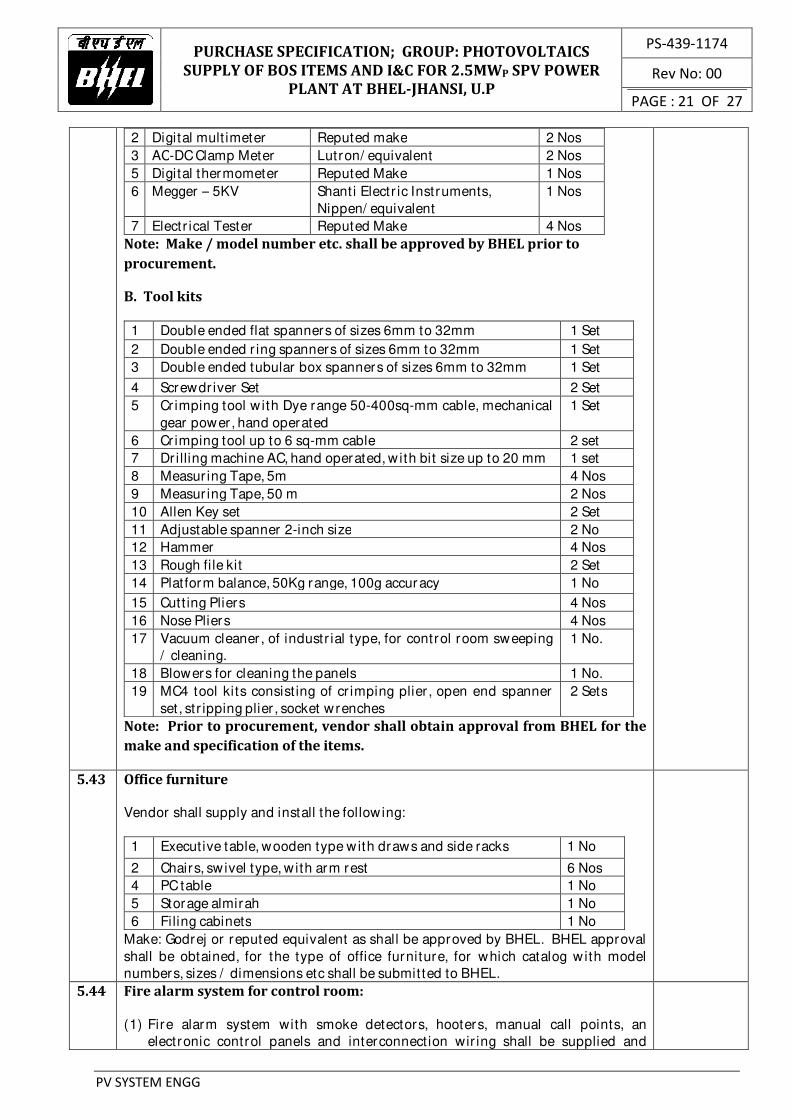
2 Digital mult imeter Reputed make 2 Nos
3 AC-DC Clamp Meter Lutron/ equivalent 2 Nos
5 Digital thermometer Reputed Make 1 Nos
6 Megger – 5KV Shanti Electr ic Instruments,
Nippen/ equivalent
1 Nos
7 Electr ical Tester Reputed Make 4 Nos
Note: Make / model number etc. shall be approved by BHEL prior to
procurement.
B. Tool kits
1 Double ended flat spanners of sizes 6mm to 32mm 1 Set
2 Double ended r ing spanners of sizes 6mm to 32mm 1 Set
3 Double ended tubular box spanners of sizes 6mm to 32mm 1 Set
4 Screwdr iver Set 2 Set
5 Cr imping tool w ith Dye range 50-400sq-mm cable, mechanical
gear power , hand operated
1 Set
6 Cr imping tool up to 6 sq-mm cable 2 set
7 Dr illing machine AC, hand operated, w ith bit size up to 20 mm 1 set
8 Measur ing Tape, 5m 4 Nos
9 Measur ing Tape, 50 m 2 Nos
10 Allen Key set 2 Set
11 Adjustable spanner 2-inch size 2 No
12 Hammer 4 Nos
13 Rough fi le kit 2 Set
14 Platform balance, 50Kg range, 100g accuracy 1 No
15 Cutt ing Pliers 4 Nos
16 Nose Pliers 4 Nos
17 Vacuum cleaner , of industr ial type, for control room sweeping
/ cleaning.
1 No.
18 Blowers for cleaning the panels 1 No.
19 MC4 tool kits consist ing of cr imping plier , open end spanner
set, str ipping plier , socket wrenches
2 Sets
Note: Prior to procurement, vendor shall obtain approval from BHEL for the
make and specification of the items.
5.43 Office furniture
Vendor shall supply and install the following:
1 Executive table, wooden type with draws and side racks 1 No
2 Chairs, swivel type, w ith arm rest 6 Nos
4 PC table 1 No
5 Storage almirah 1 No
6 Filing cabinets 1 No
Make: Godrej or reputed equivalent as shall be approved by BHEL. BHEL approval
shall be obtained, for the type of office furniture, for which catalog w ith model
numbers, sizes / dimensions etc shall be submitted to BHEL.
5.44 Fire alarm system for control room:
(1) Fire alarm system with smoke detectors, hooters, manual call points, an
electronic control panels and interconnect ion wir ing shall be supplied and

PURCHASE SPECIFICATION; GROUP: PHOTOVOLTAICS
SUPPLY OF BOS ITEMS AND I&C FOR 2.5MWP SPV POWER
PLANT AT BHEL-JHANSI, U.P
PS-439-1174
Rev No: 00
PAGE : 22 OF 27
PV SYSTEM ENGG
installed. Make: Zicom/ Notifier / Ravel or any other reputed equivalent as shall
be approved by BHEL.
(2) Control panels in sheet steel enclosure, power coated finish, shall be a
microprocessor based system with central processing unit , input / output
modules, power supply w ith battery and battery charger , control electronics
and display mechanisms. The panel shall be a 4 zone system with audio-visual
provisions (LED indicat ions and beeps) for zone-wise annunciat ion. Individual
detector -w ise traceability / addressability is not required. It shall have
provisions for acknowledgement of alarm and manual resett ing. Batter ies used
shall be lead acid maintenance free type provided with connect ing leads.
(3) Smoke detectors shall be of conventional / opt ical / photoelectr ic type. It shall
not be of ionizat ion type that employs radioact ive mater ials.
(4) Electr ical hooters shall sound the alarm upon detect ion of smoke by the
detectors.
(5) Manual call point shall be w ith high-gloss finish, alarm LED provision, breakable
glass unit , hammer and chain.
(6) All the system components shall be installed and commissioned using suitable
w ir ing using copper cable, min. 2C x 1.5 sq-mm, armoured, fire retardant low
smoke PVC, of required length, as approved by BHEL. Cable shall be laid in PVC
conduit and fixed to the ceiling of control room.
(7) Sufficient quantity of sensors, alarms, hooter , manual call points etc. shall be
supplied and installed as per the necessary statutory requirements. Vendor
should ensure the design of fire protect ion system in line w ith the regulat ions of
the Fire Safety depar tment of the state.
(8) Vendor shall submit fire alarm layout/ scheme along with the detailed BOM to
BHEL for approval.
(9) Fire alarm control panels shall have provision for RS-485 Modbus output so
that status can be monitored in plant SCADA system.
5.45 Other safety related items
(1) Safety gadgets:
1 Gas Mask 2 Nos
2 First Aid Box with essential medicines and bandage cotton,
ant ibiot ic cream, Dettol, etc.
2 set
3 Hand Gloves 1KV for Maintenance of SMB 2 sets
4 Safety Helmet 5 Nos
5 Rain Coat 2 Nos
(2) Fire ext inguishers and sand buckets, as per the regulat ions of the Fire safety
depar tment of the state, shall be supplied and commissioned at the power plant.
BHEL approval shall be obtained for locat ions at which they shall be kept.
Quantit ies mentioned below are minimum. Vendor to comply the requirements
of statutory bodies.
1 Dry powder fire
ext inguisher
(stored pressure
type)
Capacity: 9 Kg
IS: 2171, IS:10658
CM/ L-7759096
Suitabili ty for Class A, B & C fire, related
to solid combustibles, flammable liquid
and gases.
3 Nos

PURCHASE SPECIFICATION; GROUP: PHOTOVOLTAICS
SUPPLY OF BOS ITEMS AND I&C FOR 2.5MWP SPV POWER
PLANT AT BHEL-JHANSI, U.P
PS-439-1174
Rev No: 00
PAGE : 23 OF 27
PV SYSTEM ENGG
2 Carbon di-oxide
(CO2) type fire
ext inguisher with
trolley
Capacity: 9 Kg
IS: 2878
Suitabili ty for Class B&C fires
Involving flammable liquids & gases,
electronic equipment.
3 Nos
2 Sand buckets GI fire buckets (as per IS: 2546) w ith
suitable steel stand and cover
ar rangement. All i tems shall be painted
with red oxide and BHEL approved red
paint.
BHEL approval shall be obtained for the
overall ar rangement.
Each set of stand shall car ry four sand
buckets. A suitable cover shall be
designed and provided to protect the
buckets from rain.
2 sets
5.46 Spares to be supplied along with main supply:
a) MC4 Connectors – 130 Pairs
b) Indoor type HT terminat ion kit - 1 set
5.47 Pre-commissioning inspections / checks / tests and coordination with state
departments for necessary approvals and clearances for commissioning,
synchronization with grid and post-commissioning operation of the plant:
(B) Vendor shall car ry out following minimum pre-commissioning checks:
(1) Ver ificat ion of firmness of terminat ions in all electr ical equipment: SMBs,
PCUs, VCB panel, t ransformer, SCADA stat ions, weather monitor ing
equipment and PV array ear thing.
(2) Ver ificat ion of ear thing for all these electr ical equipment.
(3) Measurement and ver ificat ion of parameters at str ing monitor ing boxes at
solar ar ray field: str ing current, voltage, combined SMB output current,
module temperature, SMB temperature.
(4) Measurement and ver ificat ion of parameters on DC input side of PCUs: DC
current and voltage; Vendor shall suppor t the PCU engineer on these tests.
(5) Insulat ion resistance measurements (megger tests) for all the electr ical
equipment of control room.
(6) Functional checks for PCUs: Vendor shall suppor t the PCU engineer dur ing
the pre-commissioning tests.
(7) Functional checks for transformer marshalling box:
Availabili ty of AC/ DC power supply, (b) Responses of the relays at VCB
panels and corresponding indications at annunciation panel by simulat ing
the alarm / tr ip of WTI at marshalling box.
(8) Functional checks for VCB panels:
(a) Availabili ty of AC/ DC power supplies (b) VCB on/ off, (c) spr ing
charging, (d) LED indicat ions, (e) functioning of electromagnetic and
numer ical relays, (f) responses at VCB panels to operat ions from SCADA
(g) indicat ions on windows, alarm accept/ reset operat ions / SCADA.
(b) Ver ificat ion of inter lock operat ions related to incomer and outgoer
VCBs.
(9) Ver ificat ion of parameters at SCADA stat ion: (a) DC/ AC parameters from
SMBs, HT panels, ACDB panels, Meter ing panels, (b) status of ACB/ VCB
breakers and transformer protect ion relays, (c) weather monitor ing
parameters.

PURCHASE SPECIFICATION; GROUP: PHOTOVOLTAICS
SUPPLY OF BOS ITEMS AND I&C FOR 2.5MWP SPV POWER
PLANT AT BHEL-JHANSI, U.P
PS-439-1174
Rev No: 00
PAGE : 24 OF 27
PV SYSTEM ENGG
(10) Functional checks on SCADA software: mimic diagrams, trend
graphs, remote accessibili ty etc.
(11) Earth resistance measurements at the electrode chambers for solar
ar ray, control room panels and switch yard equipment.
(C) Pre-commissioning tests on transformers, vacuum circuit breaker , relays, etc:
(1) Usually per formed tests are indicated as below. However , exact type of
tests required to be conducted at site prior to commissioning shall be in line
w ith STATE ELECTRICITY SUPPLY & TRANSMISSION BOARDS/ CEIG/ SECI
etc., requirements.
(a) Transformers: IR tests, rat io tests, excitat ion current measurement,
magnetic balance test on HV, shor t circuit test, excitat ion test LV side,
vector group test.
(b) 11KV vacuum circuit breaker panels: IR tests and cont inuity tests for
panels, IR values for CTs/ PTs, excitat ion test on CTs, pr imary inject ion
tests for CTs, rat io test for PTs
(c) Relays in VCB panels: open/ close, tr ipping, pr imary inject ion tests.
(d) Lightning ar restors: IR tests
(2) Appropr iate test ing agency shall be ar ranged for the tests.
(3) Vendor shall coordinate / liaison with concerned STATE ELECTRICITY
SUPPLY & TRANSMISSION BOARDS/ MRT depar tments to fix up test
schedules and witness by their representatives.
(4) Vendor shall prepare and submit the repor ts to STATE ELECTRICITY
SUPPLY & TRANSMISSION BOARDS/ MRT/ CEIG/ SECI and obtain their
approval through necessary liaison act ivit ies.
(D) Vendor shall coordinate and liaison with STATE ELECTRICITY SUPPLY &
TRANSMISSION BOARDS/ CEIG etc., prepare and submit the applicat ions w ith
necessary enclosures on behalf of BHEL and obtain their approval:
(a) Approval for BHEL drawings
(b) Approval for synchronizat ion of plant w ith gr id.
(c) CEIG inspection of power plant
(d) Provisional CEIG clearance to proceed with commissioning
(E) Vendor shall take approval of BHEL for appointing Electr ical consultant for the
ent ire SPV plant and switch yard to comply with CEIG norms and gett ing
approvals.
(F) Vendor shall implement correct ive steps on the observat ions of CEIG, follow-up
with them and obtain final clearance for licensed operat ion of the plant on a
cont inuous basis.
Note: Scope of coordinat ing w ith state departments such as STATE ELECTRICITY
SUPPLY & TRANSMISSION BOARDS, CEIG to get the clearances / approvals for
licensed / statutory operat ion of the power plant on a cont inuous basis includes all
t ransact ions required for successful liaison and clearances. Applicat ion fees and
renewal fees (say, in the form of DD) to be enclosed with applicat ion / renewal
documents and all other expenses in the above process shall be in the scope of
vendor .
6.0 Tests at manufacturer / sub-vendor works and witnessing by BHEL
6.1 BHEL shall w itness rout ine / acceptance tests per formed at manufacturer works for
following items. Vendor shall accordingly provide inspect ion call to BHEL, w ith
submission of quality assurance plan to BHEL in advance.
1) All cables under vendor scope (LT, data, control and communicat ion cables)
2) Earthing electrodes & ear th str ip
3) Lightning ar restor (ESE)
4) Fire alarm system

PURCHASE SPECIFICATION; GROUP: PHOTOVOLTAICS
SUPPLY OF BOS ITEMS AND I&C FOR 2.5MWP SPV POWER
PLANT AT BHEL-JHANSI, U.P
PS-439-1174
Rev No: 00
PAGE : 25 OF 27
PV SYSTEM ENGG
5) ACDB
6) UPS with battery
Note: In case the item is bought out from dealers, test cer tificates, as per relevant IS
/ IEC standards, as issued by manufacturer shall be submitted to BHEL. However ,
pr ior approval shall be obtained from BHEL for procurement of the item from
dealers.
7.0 General conditions applicable during installation and commissioning phase
7.1 All machinery such as cranes, hydra, JCBs, forklifts, t ranspor t trucks, trolleys etc
necessary for movement of mater ials shall be organized by the vendor .
7.2 All necessary tools and tackles such as cr imping tool ( including heavy duty tools for
cr imping cables), screw dr iver set, power screwdr ivers, cutt ing pliers, nose pliers,
spanner sets, adjustable spanners, hole saw cutter set, bending tools, torque
wrenches, hack saw blades, pipe wrenches, flat / r ound fi les, HV terminat ion tools,
dr i lling machines, welding machines, concrete mixers, steel bar bending tools /
templates for RCC works, spade, shovel, hammer etc shall be organized by the
vendor .
7.3 All necessary measur ing instruments such as digital mult imeters, electr ical testers,
meggers (1kV, 2.5kV, 5kV), lamp load testers for solar ar ray str ing measurements,
ear th resistance meters, weighing machines, water level indicators etc shall be
organized by the vendor .
7.4 Vendor shall make their own arrangements for necessary food, dr inking water and
accommodation for their labour and employees posted at the site. Similar ly, food
and drinking water required at the site, dur ing the construct ion operat ions, shall
also be in scope of vendor .
7.5 Vendor shall organize all necessary steps to meet statutory requirements such as
labour license, PF, ESI etc and also ensure compliance with relevant acts such as
minimum wages act, income tax act, employee insurance act, BOCW act etc for their
labour deployed at site.
7.6 Vendor shall maintain updated labour register , w ith name, age, qualificat ion, salary,
attendance details etc at the site. Vendor has to sat isfy all the statutory
requirements as per the labour law regulat ions in the state.
7.7 Vendor shall use danger boards, wherever required, to ensure safety of the persons
dur ing the work at site.
7.8 Vendor shall adhere to all necessary safety norms such as use of helmet, goggles,
hand gloves, gumboots, aprons etc. It is the ult imate responsibili ty of the vendor in
all respect to prevent accidents at the site and safeguard their labour from
accidents.
7.9 Vendor shall, at the complet ion of every work, clear off the debr is, which resulted
out of the work. In case of excavat ion work such as cable trench etc, vendor shall
finish the land neatly w ith necessary leveling, rolling etc.
7.10 Vendor shall car ry out the work w ithout causing inconvenience to other contract
groups at the site. In case of conflicts w ith other groups, vendor shall ensure that
the matter is resolved at once amicably so that the progress of work is not affected.
7.11 Any damages on the building, structures etc attr ibutable to the acts of labour /
employees of vendor shall be rect ified and made good by the vendor at their own
cost.
7.12 No child labour shall be employed for execut ion of the present contract.

PURCHASE SPECIFICATION; GROUP: PHOTOVOLTAICS
SUPPLY OF BOS ITEMS AND I&C FOR 2.5MWP SPV POWER
PLANT AT BHEL-JHANSI, U.P
PS-439-1174
Rev No: 00
PAGE : 26 OF 27
PV SYSTEM ENGG
7.13 Any miscellaneous materials, which are found essential for technical
completion of the contract as per regulations/standards but not mentioned
explicitly in this specification, shall be deemed to be included in the
specification. Accordingly, such materials shall be included by the vendor as
part of the offer.
7.14 In certain cases, approximate quantities are only mentioned. This is for the
purpose of providing guidance to vendors and are as per BHEL estimation.
Such quantities shall, therefore, be considered only indicative. Vendor shall,
however, take into account the exact quantities that shall be required to meet
the functional requirements of I&C activities as per clause 5.0.
7.15 Special instruct ion for ear thing:
In compliance with Rule 33 and 61 of Indian Electr icity Rules, 1956 (as amended up
to date), all non-current carrying metal par ts shall be ear thed with two separate and
dist inct ear th cont inuity conductors to an efficient ear th electrode. Accordingly, all
cases such as cable suppor t structures, cable ladders, cable trays (control room) etc
shall be ear thed.
7.16 Any deviat ions shall be discussed with BHEL site engineers and implementat ion
shall be taken up only after approval from BHEL.
7.17 Vendor shall submit per iodic status repor t, on daily as well as weekly consolidated
basis, to BHEL on the progress of the contract.
7.18 Vendor has to design all the foundations required as per this specificat ion based on
the soil repor t and site condit ions and to be submitted to BHEL for approval before
construct ion. However , minimum requirements are specified in this specificat ion
for ready reference. Soil repor t w ill be made available to vendor after placement of
PO upon request.
7.19 Supply and installat ion of all auxiliary supply cables from ACDB to var ious plant
equipment viz., FCBC, building light ing etc., shall be in the scope of the vendor which
w ill be int imated from t ime to time.
7.20 All cable terminat ions shall be done in such a way that bending radius of the cable is
str ict ly as per IS: 1255
7.21 In case project is not completed as per BHEL scope due to reasons ar ising out of
mater ials from BHEL end/ vendor ’s end, contractor has to complete the job at later
stage without any extra charges. No overrun charges shall be paid in case of
extension of project schedules
7.22 Vendor shall prepare and submit as-built drawings after execut ion of works.
8.0 Defect Liability Period
8.1 Date of commencement of defect liabili ty per iod :
Zero date for defect liabili ty per iod shall be the actual date on which the complete
7.5 MW capacity is commissioned with synchronizat ion / expor t of power to 11kV
gr id and complet ion of all the works in the scope of the vendor .
8.2 Work dur ing defect liabili ty per iod:
Vendor shall post competent person/ s at site on daily basis to attend the problems
that may ar ise in the plant dur ing defect liabili ty period w ithin 24 hours.

PURCHASE SPECIFICATION; GROUP: PHOTOVOLTAICS
SUPPLY OF BOS ITEMS AND I&C FOR 2.5MWP SPV POWER
PLANT AT BHEL-JHANSI, U.P
PS-439-1174
Rev No: 00
PAGE : 27 OF 27
PV SYSTEM ENGG
9.0 Documents to be submitted for BHEL approval after receipt of purchase order
9.1 BHEL approval shall be obtained for the following technical documents, which
shall be submitted to BHEL in phased manner based on pr ior ity sequence of
act ivit ies. However , it shall be ensured that all documents are submitted w ithin
14 days from date of purchase order .
9.2 Vendor , make, model number / par t number , specificat ion / sizes / dimensions /
drawings / datasheets of all the vendor supplied items.
9.3 General ar rangement drawings/ schemes/ layouts etc. w ith bill of mater ials /
quantit ies shall be submitted for the following (list is indicat ive and not limited
to):
(1) SMB Mounting structure
(2) Cable trench layout in ar ray yard
(3) Details of power , control, communicat ion cable
(4) ESE Lightning ar restor ar rangement w ith foundation details
(5) Yard lights –compound wall, approach road.
(6) Water pipeline layout from storage tank to solar ar ray field for module
cleaning system with pressure calculat ions
(7) Fire alarm system scheme / layout
(8) Cable suppor t structures and cable ladders w ithin control room
(9) Cable suppor t structure for LT cables between inver ters and transformers
9.4 Quality assurance plans for items listed under clause 6.0
9.5 Detailed act ivity-t ime char t for project implementat ion.
9.6 Detailed manpower deployment schedule.
10.0 Codes and Standards:
IS:7098
(Par t -I)
Specificat ion for XLPE insulated PVC sheathed cables. Par t-I: For working voltages
up to 3.3 KV
IS:7098
(Par t -II)
Specificat ion for XLPE insulated PVC sheathed cables. Par t-I: For working voltages
from 3.3 KV up to and including 33 KV
IS:1554
(Par t-I)
Specificat ion for PVC insulated cables for working voltages upto and including 1100V
IS : 3975 Low Carbon Galvanized steel w ires, formed wires and tapes for armour ing of cables
IS : 4905 Methods for random sampling
IS : 5831 PVC insulat ion and sheath of electr ical cables
IS : 8130 Conductors for insulated electr ical cables and flexible cords
IS : 10418 Specificat ion for drums for electr ic cables
IS : 10810 Methods of tests for cables
IS: 1255 Code of pract ice for installat ion and maintenance of power cables up to and including
33 KV rat ing

Indoor HT Panel
50x6mm Flat
Earthing Strip Riser
VCB11KV,630A,25KA for 1 sec
Line PT
11KV3
110V3
Core1: CL-0.2,50VA
Core2: CL-0.5,50VA
SURGE DIVERTER
BCS
H1 H2 H3 H6 H7 H8H4 H9H5
L/R
C.T
Core 1: 150/1A
CL-5P20, 5VA
9kv/10kA
Core 2: 150/1A
CL-0.5, 5VA
FuseFuse
Inverter 1250KW
2500A, TP, 50kA EDOType ACB.
50x6mm Flat Earthing
Strip Riser
ACB
Per phase 7Rx1Cx300 Sq.mm XLPE Al.Ar.Cable
Grade 1.1KV
(In air on trays)
S/C rating of cable 28.2kA/1 sec
Earth Strip/cable
2700 kVA,
350V, 350V/11KV
Dyn11,yn11 ,OCTC
Float neutral
Dry Type TFMR
M
Sl.No. DESCRIPTIONSYMBOL
1.
2.
3.
4.
5.
6.
19.
20.
21.
22.
23.
24.
25.
26.
INVERTER(PCU)1250kVA27 59 50 51
AC DC
cu.cable cu.cable
Air Circuit Breaker 2500 A, TP,EDO
Indoor H.T Panel
Current Transformer
Fuse
Vaccum Circuit Breaker
86
95
H1 BREAKER IN SEVICE
SPRING CHARGING
BREAKER IN TEST
BREAKER ON
BREAKER OFF
PHASE-R
PHASE-Y
PHASE-B
BREAKER TRIP
L/R
BCS BREAKER CONTROL SWITCH
27.
28.
29.
30.
31.
32.
33.
34.
35.
37.
36.
LEGEND DETAILS
LOCAL/REMOTE SELECTOR SWITCH
Three winding 2700KVA, Dry Type TFMR.
95sq.mm 95sq.mm
7.
8.
9.
10.
11.
12.
AC Alternating current
DC Direct Current
27 Under Voltage Relay
59 Over Voltage Relay
50
13.
14.
15.
17.
18.
MFM Multi function Meter
4 Core PotentialTransformer
Master trip relay
Trip circuit supervision relay
Idmt earth fault relay
Idmt over current relay
Inst.over current relay
Tt
50N Neutral Instantaneous Overcurrent
H2
H3
H4
H5
H6
H7
H9
H8
Anti Pumping Relay 94
80DC DC circuit supervision relay
16.
1 9
2RX1CX240SqmmX1.1kV
armored XLPE Al.cable.
1.25MWp SPV ARRAY
2RX1CX6 SqmmX1.1kV
UnArmored Cu Cable
SMU24/1
TYPE
3-679-05-009023-679-05-00902
VCP
1RX3Cx240 Sq.mm
XLPE Al.Ar.Cable
Grade 11KV
GS 50x6mmFlat
Earthing Strip Riser
VCB11KV,630A,25KA for 1 sec
Line PT11KV
3110V
3Core1 :CL-0.5,50VA
Core2 :CL-3P,50VA
SURGE DIVERTERBCS
H1 H2 H3 H6 H7 H8H4 H9H5
L/R
C.T
Core 2:75 /1A
CL-5P20,10VA
11kv/25kA
RAP
Core 1:75 /1A
CL-0.5S,10VA
FuseFuse
01
01
00
110V3
PLANTACDB
Off circuit tap changerOCTC
Inverter 1250KW
2500A, TP, 50kA EDOType ACB.
ACB
Earth Strip/cable
1 9
2RX1CX240SqmmX1.1kV
armored XLPE Al.cable.
1.25MWp SPV ARRAY
2RX1CX6 SqmmX1.1kV
UnArmored Cu Cable
SMU24/1
TYPE
MS
Core 3: 150/1A
CL-0.2S, 5VA
110V3
TO BHEL-JHANSI 11kV SWITCHYARD
(CABLING JHANSI SCOPE)
Ta Transformer Alarm
Transformer Trip
ACDB Alternating Current Distribution Board
TEM Tariff Energy Meter
Auxiliary power input (Jhansi scope)Total capacity required 30kVA
Core3: CL-3P,50VA

TEMPLE
NA
LLA
NA
LLA
NA
LL
A
NA
LL
A
RO
AD
N.H
.
RO
AD
RO
ADR
OA
D
RO
AD
RO
AD
ROAD
GATE
CISF COLONY
GATENEAR CISF COLONY
GATE NEARNALLAHTO NH
LEGEND
BOUNDARY WALL OFBHEL FACTORY
ROAD AL AROUNDBHEL LAND
BOUNDARY WALL OFBHEL LAND
AREA OFSOLAR PLANT
ADMN.
PLANTROOM
PLANTROOM
SUB.
STORE
LAWN
LAWN
LAWN
LAWN
LAWN
GAURD ROOM
FH-56
FH-55
STATION
R O
A
D
250KL CWR SUMP FOR OHT
600KL OVER HEAD TANK
UNDERGROUNDTANK
FENCING
TEMPLE
BOUNDARY WALL450MM WIDE
ROAD4 M WIDE
10M
NALLA
62.53
5m
123.0
4
38.7916.6
0151.78
174.15
128.42
119.13
32.7823.83
14.17
DATE
NO. OF SHEET-1
SOLAR-PLAN-002LAND FOR SOLAR POWER PLANT
BHARAT HEAVY ELECTRICALS LIMITED
JHANSI
TITLE
DRN.
CHD.
APPD.
SHEET NO.-1
DRAWING NO.
NAME SIGN
REV.
00
S.S. AGNIHOTRI
K D GUPTA
26/08/2017
D.K MAHATO
BUILING
BHEL JHANSIFACTORY
N
SL
OP
E
SL
OP
E
SL
OP
EC
NOTE- LAND SLOP 1:75
AREA OF SOLAR PLANT
A=2550B=9275C=15000TOATL=49775 SQ. M1 ACRE=4028SQ. MTOTAL AREA OF LAND = 12ACRE
PR0JECT : 2.5MWp SOLAR POWER PROJECT
CUSTOMER : BHEL JHANSI
00
FIRST ISSUE
NUMBER OF TABLE:416
3.5
4
3.5
7
100.2
TYPICAL ARRANGEMENT OF MODULE TABLE
SI.NO. SMB NO. LENGTH TO CONTROL ROOM
1 SMB 1 125.12
2 SMB 2 167.76
3 SMB 3 210.40
4 SMB 4 260.15
5 SMB 5 215.26
6 SMB 6 186.83
7 SMB 7 158.70
8 SMB 8 129.98
9 SMB 9 101.55
10 SMB 10 73.12
11 SMB 11 44.66
12 SMB 12 65.76
13 SMB 13 87.08
14 SMB 14 108.40
15 SMB 15 129.72
16 SMB 16 158.15
17 SMB 17 186.57
18 SMB 18 200.86
TOTAL 2610.07
CABLE TRENCH(CABLE ROOT OF THE PANEL OUTPUT WITH THE
PCU INPUT)
NA
LL
A
NA
LL
A
FENCING
LAND SUITABLE FORSOLAR PLANT
NALLA
151.78
174.15
BHEL JHANSIFACTORY
SL
OP
E
SL
OP
E
SL
OP
E
A
B
SMB1
SMB2
SMB3
SMB5
SMB6
SMB7
SMB8
SMB9
SMB10
SMB11
SMB13
SMB14
SMB17
SMB4
BOUNDARY WALLOF BHEL FACTORY
234M
10M
5M
4M
260M
BOUNDARYWIRE FWENCING
BOUNDARYWIRE FWENCING
4 M WIDEPROPOSED ROAD
34M
61M
10M
105M
4M
4M
106M
156M
CONTROLROOM
CR
14.5x9m
4 M
SMB12
SMB15
SMB16
SMB18

LEGEND
NOTES