
PURCHASE SPECIFICATION FOR VIBRATION MONITORING …
37
A4-10 REF. : CE/416/VMS/OT/PS REV. NO. : 00 PAGE : 1 0F 9 PURCHASE SPECIFICATION FOR VIBRATION MONITORING SYSTEM (VMS) COPYRIGHT AND CONFIDENTIAL THE INFORMATION ON THIS DOCUMENT IS THE PROPERTY OF BHARAT HEAVY ELECTRICALS LIMITED . IT MUST NOT BE USED DIRECTLY OR INDIRECTLY IN ANY WAY DETRIMENTAL TO THE INTEREST OF THE COMPANY. REVISION : 00 APPROVED S. K. TOPPO PREPARED D. GHOSH ISSUED 416 DATE 05/01/2021
Transcript of PURCHASE SPECIFICATION FOR VIBRATION MONITORING …
A4-10
REF. : CE/416/VMS/OT/PS
REV. NO. : 00
PAGE : 1 0F 9
PURCHASE SPECIFICATION FOR
VIBRATION MONITORING SYSTEM (VMS)
CO
PY
RIG
HT
AN
D C
ON
FID
EN
TIA
L
TH
E I
NF
OR
MA
TIO
N
ON
TH
IS D
OC
UM
EN
T I
S T
HE
PR
OP
ER
TY
OF
BH
AR
AT
HE
AV
Y E
LE
CT
RIC
AL
S
LIM
ITE
D . I
T M
US
T N
OT
BE
US
ED
DIR
EC
TL
Y O
R I
ND
IRE
CT
LY
IN
AN
Y W
AY
DE
TR
IME
NT
AL
TO
TH
E I
NT
ER
ES
T O
F T
HE
CO
MP
AN
Y.
REVISION : 00
APPROVED
S. K. TOPPO
PREPARED
D. GHOSH
ISSUED
416
DATE
05/01/2021
Purchase Specification for
Vibration Monitoring System (VMS)
Ref.: CE/416/VMS/OT/PS REV.NO.: 00 PAGE : 2 of 9
Note to Bidders: Any change in scope / specification, during technical evaluation of the offers, will be communicated only to the participating bidders for this tender. AA Scope: Vendor shall offer Vibration Monitoring System (VMS) for Plant Auxiliaries namely Turbine Driven Boiler Feed Pump – TDBFPs, Motor Driven Boiler Feed Pump-MDBFP & its Motor, Cond. Extr. Pump – CEP & its motors, DMCW Pumps & its Motors, ACW Pumps & its Motors, ID Fans & its Motors, FD Fans & its Motors and PA Fans & its Motors, Mill motors, APH Was pumps & its motors, IAC Motors and SAC motors for 2 Units of Super Thermal Power Plant 660 MW or 800 MW project. Technical requirements for the above machines are as per Cl. DD of this Purchase specification. Scope of Supply shall include Engineering, Manufacturing & Testing, and Erection & Commissioning activities and Training as per this specification. Note: The sensor mounting hardware, extension cables, junction boxes, panel, networking components, display unit are optional items. The supply requirement for these OPTIONAL items will be decided later. BB Provenness Criteria: Offered System for this package shall have at least one year’s satisfactory operation in one power station having unit rating of 500 MW or above for similar application / ratings of machines. Vendor shall furnish a complete list of bought out items (i.e., items not from manufacturing range) which the Vendor has included in his proposal along with the names of proposed sub-vendors as a part of his proposal. Following documents are required for acceptance of proven track record (PTR) of the offered system:
1. Reference List of Projects wherein offered system, with model numbers of sensors & monitors, which are supplied & commissioned, along with details of machines & similar measurements and Year of Commissioning of the system specified in Projects. Reference list shall contain name of end user, latest contact email id and contact telephone number.
2. Minutes of meeting with end user for commissioning and handing over. 3. Unpriced purchase order copy 4. Certificate issued by end user mentioning the date of installation, model number of the supplied
system and date issue of end user certificate Note: If BHEL is unable to verify the PTR furnished, with end user contact details provided above, the offer will be liable for technical rejection.
CC Standardisation and Uniformity of Hardware: Vendor shall ensure that all electronic monitors / transmitters / transducers, control hardware, and other instruments/ local devices etc. that are being furnished by the Vendor, are of the same make, series and family of hardware so as to ensure smooth and optimal maintenance, easy interchangeability and efficient spare parts management.
DD Technical Requirements:
1.0 Vibration Monitoring System ( VMS ) for Plant Auxiliaries :
1.1 Microprocessor based vibration monitoring system shall be provided for Power Plant auxiliaries
such as fans/ pumps/ motors etc. Details of these machines are as detailed in Clause No. 1.10 of
this specification.
Purchase Specification for
Vibration Monitoring System (VMS)
Ref.: CE/416/VMS/OT/PS REV.NO.: 00 PAGE : 3 of 9
1.2 The Vibration Monitoring System shall be furnished on a system basis including, vibration
transducers & Key phasor /phase marker sensors with low noise flexible cables in flexible conduit,
terminated in local terminal boxes, necessary pre-amplifier/electronics mounted in local weather
proof boxes, vibration monitors, mounting racks and cabinets etc. The vibration monitoring system
shall include all power supplies, interconnecting cabling, indicators, integrating units, signal
conditioning devices and all other accessories, erection hardware required (OPTIONAL) for
monitoring of Vibration at each point. Vendor shall provide the vibration pads (OPTIONAL).
1.3 Vendor can offer up to Four Channel Vibration Monitors. The allocation of channels shall be such
that loss of one monitor shall not affect more than one side of the bearing of one machine. In the
case of more than two channels Vibration monitors being provided by the Vendor, then one spare
monitor shall be provided mounted in the panel to take care of immediate replacement of any
failed monitors. Offered vibration monitors shall be modular in construction, plug in type.
1.4 Eddy current / Piezoelectric type transducers shall be used. The sensors shall be velocity type.
However, the finally selected sensor type shall also depend on recommendation of the equipment
manufacturer & suitable for application requirement which shall be finalized during detail
engineering and without any extra price. Transducers shall be furnished in weatherproof housing
suitable for field conditions. Cables/ cabling from transducers local JB to Vibration Monitoring
system in Control Room/ Control Equipment Room shall be provided by BHEL which will be 4 Pair
x 0.5 mm2 individual & overall shielded cable for velocity pick-up type transducers and 2 Triad x
0.5 mm2 individual & overall shielded cable for phase marker sensors (considering 50 % spare
cores). Vendor to confirm the suitability of cable size & type for their offered VMS system.
1.5 Vibration monitoring system shall give one number buffered output of 4-20 mA DC and two
numbers of buffered raw signals for each point monitored and one no. of buffered raw signal for
each Key phasor/phase marker. One buffered signal for each point monitored & phase, shall be
terminated to panel terminal blocks, which shall be taken to third party vibration analysis system.
The signal shall be suitable for use as an input to DDCMIS as well as for analog recording &
analysis, linear in proportion to vibration velocity as well as displacement. Monitor shall provide
vibration indication calibrated in velocity units along with provisions of changing to displacement
unit (field-programmable) for each measurement point in both horizontal & Vertical planes.
1.6 The Vibration monitor with power supplies shall be mounted in a separate self standing cabinet (as
per Clause No. 1.8 – OPTIONAL) to be located in Control Equipment Room for the main plant
auxiliaries and in respective offsite area control rooms for offsite auxiliaries as applicable. Vendor
shall feed the vibration monitoring cabinet from redundant 24 V DC supply. The feeders from the
respective 24 V DC chargers to vibration monitoring cabinet is in BHEL’s scope. If 240 V AC UPS
power supply is required for panel PC/ desktop PC, Mini UPS for the same shall be provided by
the vendor at respective offsite area control rooms. Redundant UPS of 240 V AC for VMS cabinet
at Control Equipment Room will be provided by BHEL. The power supply arrangement shall
ensure that if external power supplies are used, failure of one power supply shall not affect any
monitoring function in the system. Also any power supply failure/ earth fault in any of the monitors
will be isolated without affecting other monitors/ common power supply. However, if any power
supply modules internal to the monitors are envisaged, the failure of one such module should not
affect more than one monitor.

Purchase Specification for
Vibration Monitoring System (VMS)
Ref.: CE/416/VMS/OT/PS REV.NO.: 00 PAGE : 4 of 9
1.7 The functional requirement for vibration monitoring system shall include but not be limited to the
following:
1.7.1 Vibration monitor front face status indications shall be available for indications of healthy
conditions of pick up circuit, monitor circuit and power supply. On sensor fault/ wire break in the
sensor circuit, the system shall have the feature of identifying the same through suitable means
like the signal not forced to a value less than 4 mA. In case such feature is not available, then
suitable contact shall be provided from the monitor for sensor fault.
1.7.2 The facility shall be available for functional checking of monitors.
1.7.3 All vibration monitoring equipment shall be functionally tested for circuit continuity and output
response. All the components & interconnection cables shall be tested to ensure compliance with
the specification requirements & all other applicable codes & standards.
1.7.4 In case it is the proven standard practice of the vendor to provide vibration monitoring
Server/computer with TFT LCD monitor, instead of dedicated monitors with the signal conditioning
equipment in control equipment room, the same shall also be acceptable. However all relevant
functional requirements detailed above shall be met and the system shall be subject to BHEL/End-
user approval.
1.7.5 Vendor to provide 15” display panel PC.
1.8 Panel / Cabinet for VMS (OPTIONAL):
Vendor shall supply the panel for VMS as per below specification:
a. Panel shall be of size 800 mm X 800 mm X 2415 mm H ( including top canopy- 60 mm + Bottom frame 50 mm + Antivibration pad 15mm ) in mm
b. Panel shall be made up of 2mm thick CRCA steel sheet. c. Anti-vibration pad of about 15 mm shall be provided. d. Panel protection class shall be IP – 32; Panel height shall be 2415 mms. e. Door shall be provided in the front & rear sides, shall be of 2 mm thick CRCA steel sheet. f. 3 point locking system g. Paint shade/s shall be :
Exterior / Interior = RAL 9002 End Panel Colour (Exterior) = RAL 5012
h. Panel painting shall be powder coated 100 microns thick or more. i. Cutout with cable-gland plates shall be provided on the bottom of the Panel, for Cabling. j. Suitable Lifting Hooks shall be provided on the Panel. k. Provision shall be made in the Panel to accept two power supply feeders with required MCB’s. l. Terminals shall be Clip-on type for cable termination. 20 % spare terminals shall be offered. m. Illumination shall be provided in the panel.
1.9 Local Junction Box (OPTIONAL):
a. No. of ways: As required with 20% spare terminals
b. Material & Thickness: 4 mm thick Fiberglass Reinforced Polyester (FRP)
c. Type: Screwed at all four corners for door. Gasket shall be of synthetic rubber.
d. Suitable Mounting Clamps and accessories shall be offered. Material shall be of SS.
e. Type of Terminal Blocks: Rail mounted cage clamp type suitable for conductor size up to 2.5 mm2.
A M6 earthing stud shall be provided.
f. Protection Class: IP – 65 minimum for outdoor applications and shall be provided with adequate
No. of cable glands.
g. Grounding: To be provided
h. Separate JB for each of the Bearing shall be provided.
i. The JB arrangement drawing is to be furnished.
j. JB color exterior & interior shall be IS:5 631 Light Grey (Semi Glossy). Type Test for IP-65 to be
included.

Purchase Specification for
Vibration Monitoring System (VMS)
Ref.: CE/416/VMS/OT/PS REV.NO.: 00 PAGE : 5 of 9
1.10 Machine Data for VMS:
Sl. N
o.
Ma
ch
ine
Ma
ch
ine
Qty
. 1
st
Un
it
Ma
ch
ine
Qty
. 2
nd
Un
it
Ap
px.C
ab
ling
dis
t. f
rom
CC
R/ W
SC
R
(in
mtr
)
No.
of
Be
ari
ng
s f
or
mo
nito
rin
g v
ibra
tio
n
(in
X
& Y
dir
ectio
n)
Insta
llatio
n
Hori
zo
nta
l (H
) /
Ve
rtic
al (V
)
Me
asu
rem
en
t p
ara
me
ter
Ma
ch
ine
RP
M
Vib
ratio
n R
an
ge
-(m
m/s
ec-
rms)
Ala
rm L
eve
l (
mm
/se
c -
rms)
Tri
p L
eve
l (m
m/s
ec -
rm
s)
Mo
un
tin
g D
eta
ils
No o
f V
ib.
Se
nso
rs 1
-Unit
No.
of
Ph
ase
Ma
rke
r 1
-Unit
No o
f V
ib.
Se
nso
rs 2
-Unit
No.
of
Ph
ase
Ma
rke
r 2
-Unit
1Boiler Feed
Pump TDBFP 2 2 130 2 H
Rel
Shaft
800-
70000-200
p-p0-90
p-p0-150
p-p C 8 2 8 2
2 MDBFP 1 1 130 2 HRel
Shaft
800-
70000-200
p-p0-90
p-p0-150
p-p C 4 1 4 1
3 MDBFP Motor 1 1 130 2 H Abs Brg 1485 0-25 4.5 7.1 B 4 1 4 1
4Cond. Extrn.
Pump - CEP 3 3 120 1 V Abs Brg 1490 0-25 6.45 8.6 A 6 6
5 CEP - Motor 3 3 120 2 V Abs Brg 1485 0-25 4.5 7.1 B 12 12
6DMCW TG
Pump 3 3 150 2 H Abs Brg 1480 0-25 10.0 15.0 A 12 12
7DMCW TG
Pump - Motor 3 3 150 2 H Abs Brg 1480 0-25 7.0 12.0 A 12 12
8DMCW SG
Pump 2 2 150 2 H Abs Brg 1480 0-25 10.0 15.0 A 8 8
9DMCW SG
Pump - Motor 2 2 150 2 H Abs Brg 1480 0-25 7.0 12.0 A 8 8
10 Mill Motor 8 8 230 2 H Abs Brg 1000 0-25 4.5 7.1 B 32 8 32 8
11 ID Fan 2 2 460 1 H Abs Brg 590 0-25 4.5 9.0 E1 4 4
12 IDF - Motor 2 2 460 2 H Abs Brg 600 0-25 4.5 7.1 B 8 8
13 FD Fan 2 2 300 1 H Abs Brg 990 0-25 4.5 9.0 E 4 4
14 FDF - Motor 2 2 300 2 H Abs Brg 1000 0-25 4.5 7.1 B 8 8
15 PA Fan 2 2 290 1 H Abs Brg 1490 0-25 4.5 9.0 E 4 4
16 PAF - Motor 2 2 290 2 H Abs Brg 1490 0-25 4.5 7.1 B 8 8
17 ACWP 3 3 100 2 H Abs Brg 1480 0-25 10.0 15.0 B 12 12
18 ACWP Motor 3 3 100 2 H Abs Brg 1480 0-25 7.0 12.0 B 12 12
46 46 166 29 166 29
Note: 1) Mounting Details:
A: 60 x 60 x 10 mm pad on bearing housing
B: 60 mm cube vibration pad welded on both end shields
C: Mounting arrangement of sensors for TDBFPs and MDBFPs are enclosed as Annexure-A to this specification.
E / E1: 80 x 80 mm / 70 x 80 mm machined pads screwed with bearing housing respectively.
2) Cabling distance from Unit Control Room (UCR) and VMS panel in Engineering Equipment Room (EER) shall be approx 200 meter.
3) Key slot of 30 mm (L) x 15 mm (W) x 3 mm (D) are provided on connecting coupling hubs for phase angle measurement.
4) KKS Tag Nos. for transducers will be provided during detailed Engineering.
Total
Machine Data: Ref.: CE/416/VMS-D
3
3
2
3 3
2
2
2
3
3
2
2
2
2
2.0 Mandatory Spares: Vendor shall offer mandatory spares, as below with unit price:
2.1 Sensors with extension cables & Drivers: 20% or minimum 2 nos. whichever is more
2.2 Power supply module cards: 10% or minimum 2 nos. whichever is more
2.3 Driver/ Interface cards & all other electronic cards: 10% or minimum 2 nos. whichever is more
Note: In case of decimals value, next higher integer value shall be considered.
Purchase Specification for
Vibration Monitoring System (VMS)
Ref.: CE/416/VMS/OT/PS REV.NO.: 00 PAGE : 6 of 9
3.0 Start-up & Commissioning Spares:
Start-up and commissioning spares are those spares which may be required during the start-up and commissioning of the equipment/system. All spares used till the plant is handed over to the employer shall come under this category. The Bidder shall include in his scope of supply all the necessary, start up and commissioning spares and recommended spares and indicate these in their offer.
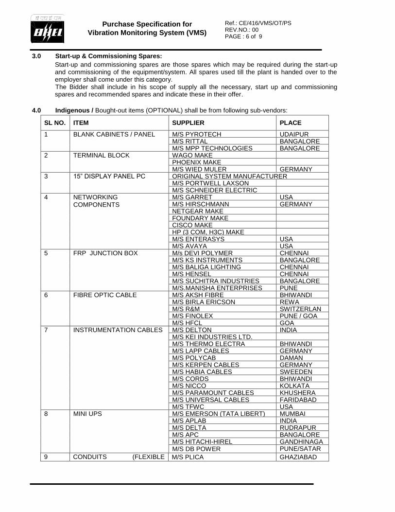
4.0 Indigenous / Bought-out items (OPTIONAL) shall be from following sub-vendors:
SL NO. ITEM SUPPLIER PLACE
1
BLANK CABINETS / PANEL
M/S PYROTECH UDAIPUR M/S RITTAL BANGALORE M/S MPP TECHNOLOGIES BANGALORE
2 TERMINAL BLOCK WAGO MAKE PHOENIX MAKE M/S WIED MULER GERMANY
3 15” DISPLAY PANEL PC ORIGINAL SYSTEM MANUFACTURER M/S PORTWELL LAXSON M/S SCHNEIDER ELECTRIC
4 NETWORKING COMPONENTS
M/S GARRET USA M/S HIRSCHMANN GERMANY NETGEAR MAKE FOUNDARY MAKE CISCO MAKE HP (3 COM, H3C) MAKE M/S ENTERASYS USA M/S AVAYA USA
5 FRP JUNCTION BOX M/s DEVI POLYMER CHENNAI M/S KS INSTRUMENTS BANGALORE M/S BALIGA LIGHTING CHENNAI M/S HENSEL CHENNAI M/S SUCHITRA INDUSTRIES BANGALORE M/S.MANISHA ENTERPRISES PUNE
6 FIBRE OPTIC CABLE M/S AKSH FIBRE BHIWANDI M/S BIRLA ERICSON REWA M/S R&M SWITZERLAN
D M/S FINOLEX PUNE / GOA M/S HFCL GOA
7 INSTRUMENTATION CABLES M/S DELTON INDIA M/S KEI INDUSTRIES LTD. M/S THERMO ELECTRA BHIWANDI M/S LAPP CABLES GERMANY M/S POLYCAB DAMAN M/S KERPEN CABLES GERMANY M/S HABIA CABLES SWEEDEN M/S CORDS BHIWANDI M/S NICCO KOLKATA M/S PARAMOUNT CABLES KHUSHERA M/S UNIVERSAL CABLES FARIDABAD M/S TFWC USA
8 MINI UPS M/S EMERSON (TATA LIBERT) MUMBAI M/S APLAB INDIA M/S DELTA RUDRAPUR M/S APC BANGALORE M/S HITACHI-HIREL GANDHINAGA
R M/S DB POWER PUNE/SATARA 9 CONDUITS (FLEXIBLE
CONDUITS) M/S PLICA GHAZIABAD
Purchase Specification for
Vibration Monitoring System (VMS)
Ref.: CE/416/VMS/OT/PS REV.NO.: 00 PAGE : 7 of 9
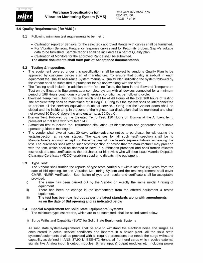
5.0 Quality Requirements ( for VMS ) : 5.1 Following minimum test requirements to be met :
Calibration report of Sensors for the selected / approved Range with curves shall be furnished.
For Vibration Sensors, Frequency response curves and for Proximity probes, Gap v/s voltage data to be furnished. Sample reports shall be included as a part of Quality plan.
Calibration of Monitors for the approved Range shall be submitted. The above documents shall form part of Acceptance documentation.
5.2 Testing & Inspection: The equipment covered under this specification shall be subject to vendor’s Quality Plan to be
approved by customer before start of manufacture. To ensure that quality is in-built in each equipment the Quality Assurance System manual & Quality Plan indicating the system followed by the vendor shall be submitted to purchaser for his review along with the offer.
The Testing shall include, in addition to the Routine Tests, the Burn-in and Elevated Temperature Test on the Electronic Equipment as a complete system with all devices connected for a minimum period of 168 Hours continuously under Energised condition as per following cycle:
Elevated Temp Test: During this test which shall be of 48 Hours of the total 168 hours of testing ,the ambient temp shall be maintained at 50 Deg.C. During this the system shall be interconnected to perform all the services equivalent to actual service. During this the Cabinet doors shall be closed and the inside temp in the zone of the highest heat dissipation shall be monitored and shall not exceed 10 Deg.C above the ambient temp. at 50 Deg.C.
Burn-in Test: Followed by the Elevated Temp Test, 120 Hours of Burn-in at the Ambient temp prevalent at that time with simulated I/O.
Simulation test to include the Disturbance simulation, its identification and generation of suitable operator guidance message.
The vendor shall give at least 30 days written advance notice to purchaser for witnessing the tests/inspection at various stages. The expenses for all such test/inspection shall be to Manufacturer’s account except for the expenses of purchaser’s representatives witnessing the test. The purchaser shall attend such test/inspection or advice that the manufacturer may proceed with the test, which shall be deemed to have in purchaser’s presence and shall furnish relevant test result and test certificates to the purchaser for his review who will then issue Material Dispatch Clearance Certificate (MDCC) enabling supplier to dispatch the equipment.
5.3 Type Test: The Vendor shall furnish the reports of type tests carried out within last five (5) years from the date of bid opening, for the Vibration Monitoring System and the test requirement shall cover CMRR, NMRR Verification. Submission of type test results and certificate shall be acceptable provided.
i) The same has been carried out by the Vendor on exactly the same model / rating of equipment.
ii) There has been no change in the components from the offered equipment & tested equipment.
iii) The test has been carried out as per the latest standards along with amendments as on the date of Bid opening and as indicated below
5.4 Special Requirement for Solid State Equipments/ Systems
The minimum type lest reports, which are to be submitted, shall be as indicated below:
i) Surge Withstand Capability (SWC) for Solid State Equipments Systems
All solid state systems/equipments shall be able to withstand the electrical noise and surges as encountered in actual service conditions and inherent in a power plant. All the solid state systems/equipments shall be provided with all required protections that needs the surge withstand capability as defined in ANSI 37.90.1/ IEEE-472.Hence, all front end cards which receive external signals like Analog input & output modules, Binary input & output modules etc. including power
Purchase Specification for
Vibration Monitoring System (VMS)
Ref.: CE/416/VMS/OT/PS REV.NO.: 00 PAGE : 8 of 9
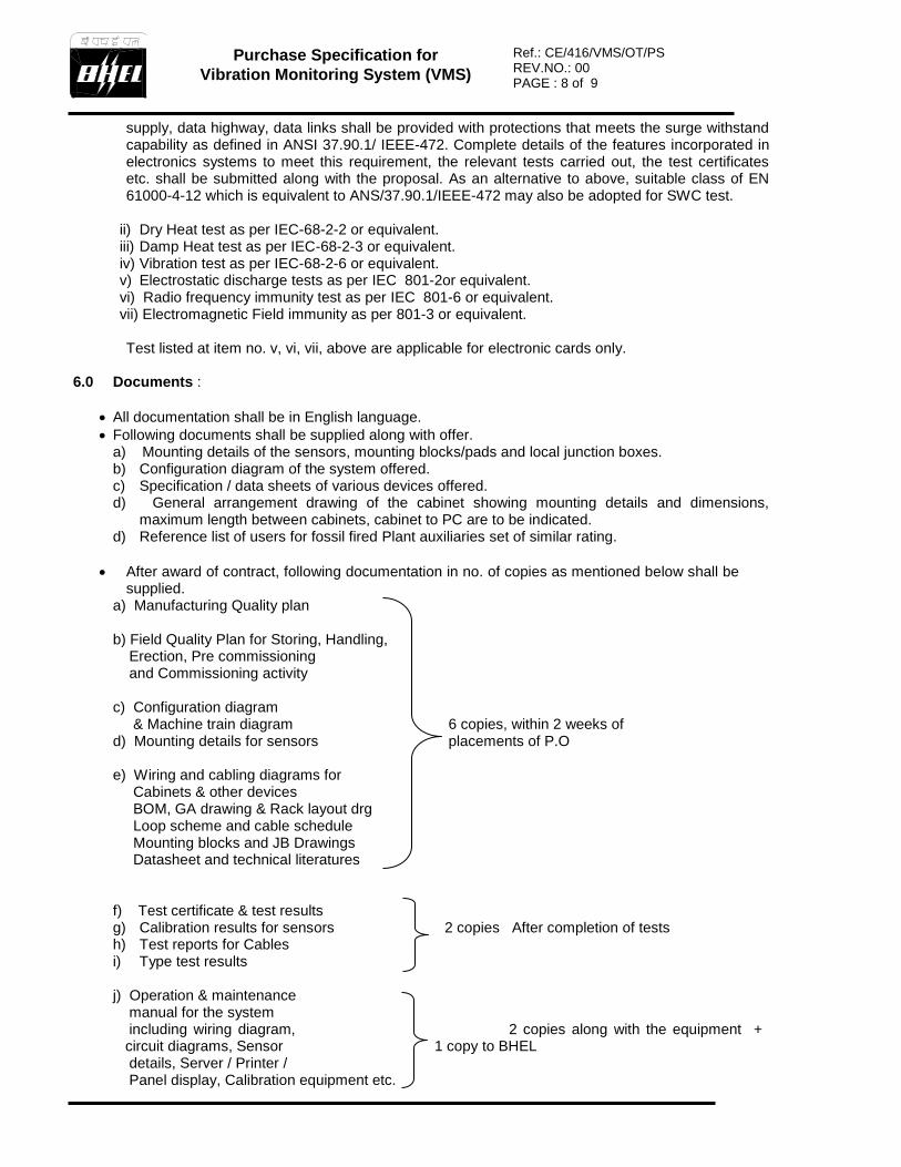
supply, data highway, data links shall be provided with protections that meets the surge withstand capability as defined in ANSI 37.90.1/ IEEE-472. Complete details of the features incorporated in electronics systems to meet this requirement, the relevant tests carried out, the test certificates etc. shall be submitted along with the proposal. As an alternative to above, suitable class of EN 61000-4-12 which is equivalent to ANS/37.90.1/IEEE-472 may also be adopted for SWC test.
ii) Dry Heat test as per IEC-68-2-2 or equivalent. iii) Damp Heat test as per IEC-68-2-3 or equivalent. iv) Vibration test as per IEC-68-2-6 or equivalent. v) Electrostatic discharge tests as per IEC 801-2or equivalent. vi) Radio frequency immunity test as per IEC 801-6 or equivalent. vii) Electromagnetic Field immunity as per 801-3 or equivalent. Test listed at item no. v, vi, vii, above are applicable for electronic cards only.
6.0 Documents :
All documentation shall be in English language.
Following documents shall be supplied along with offer. a) Mounting details of the sensors, mounting blocks/pads and local junction boxes. b) Configuration diagram of the system offered. c) Specification / data sheets of various devices offered. d) General arrangement drawing of the cabinet showing mounting details and dimensions,
maximum length between cabinets, cabinet to PC are to be indicated. d) Reference list of users for fossil fired Plant auxiliaries set of similar rating.
After award of contract, following documentation in no. of copies as mentioned below shall be supplied.
a) Manufacturing Quality plan b) Field Quality Plan for Storing, Handling, Erection, Pre commissioning and Commissioning activity c) Configuration diagram & Machine train diagram 6 copies, within 2 weeks of d) Mounting details for sensors placements of P.O e) Wiring and cabling diagrams for Cabinets & other devices BOM, GA drawing & Rack layout drg Loop scheme and cable schedule Mounting blocks and JB Drawings Datasheet and technical literatures
f) Test certificate & test results g) Calibration results for sensors 2 copies After completion of tests h) Test reports for Cables i) Type test results j) Operation & maintenance manual for the system including wiring diagram, 2 copies along with the equipment +
circuit diagrams, Sensor 1 copy to BHEL details, Server / Printer / Panel display, Calibration equipment etc.
Purchase Specification for
Vibration Monitoring System (VMS)
Ref.: CE/416/VMS/OT/PS REV.NO.: 00 PAGE : 9 of 9
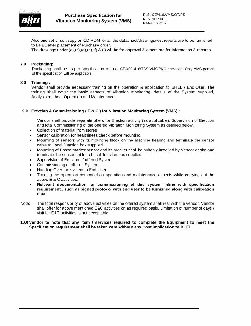
Also one set of soft copy on CD ROM for all the datasheet/drawings/test reports are to be furnished to BHEL after placement of Purchase order. The drawings under (a),(c),(d),(e),(f) & (i) will be for approval & others are for information & records.
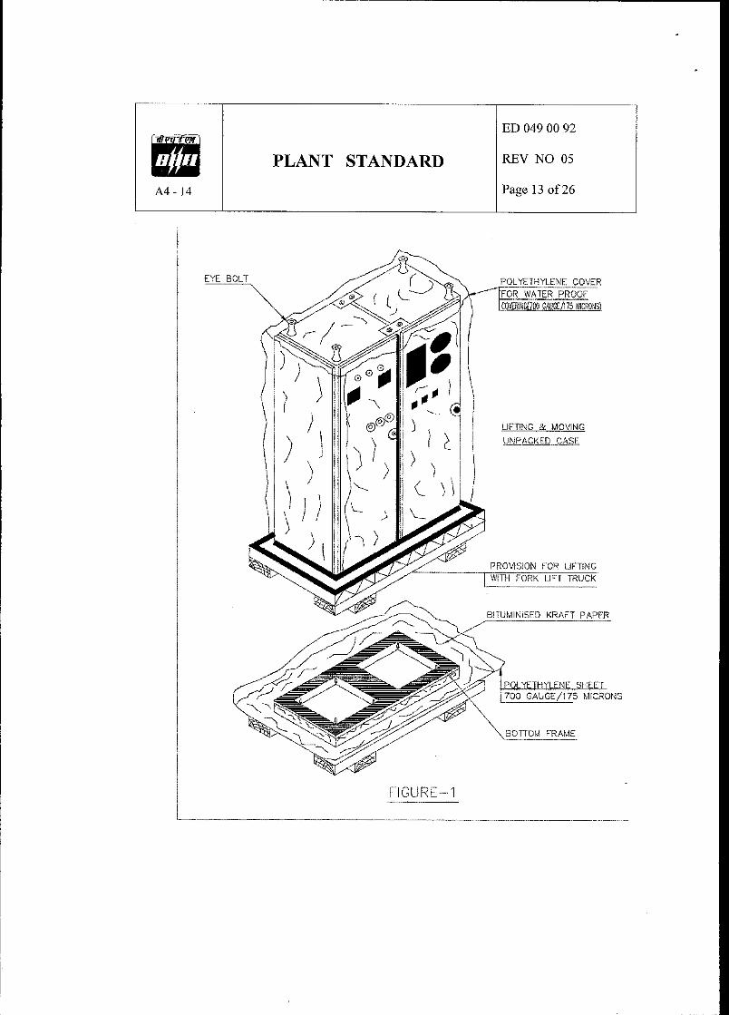
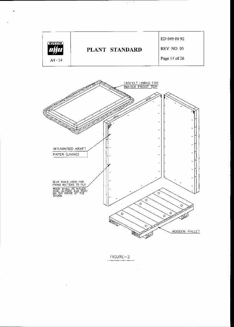
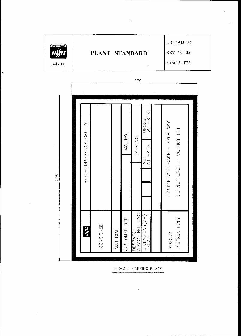
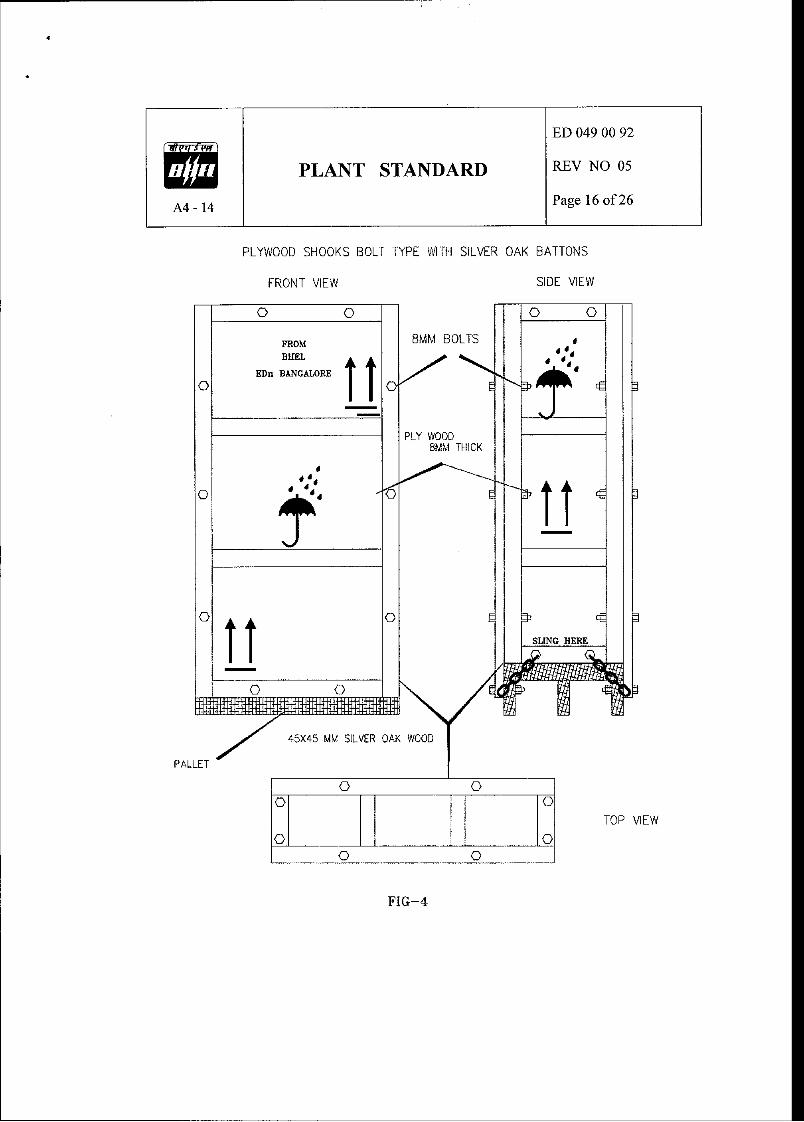
7.0 Packaging:
Packaging shall be as per specification ref. no. CE/409-416/TSS-VMS/PKG enclosed. Only VMS portion
of the specification will be applicable.
8.0 Training :
Vendor shall provide necessary training on the operation & application to BHEL / End-User. The training shall cover the basic aspects of Vibration monitoring, details of the System supplied, Analysis method, Operation and Maintenance.
9.0 Erection & Commissioning ( E & C ) for Vibration Monitoring System (VMS) :
Vendor shall provide separate offers for Erection activity (as applicable), Supervision of Erection and total Commissioning of the offered Vibration Monitoring System as detailed below.
Collection of material from stores
Sensor calibration for healthiness check before mounting.
Mounting of sensors with its mounting block on the machine bearing and terminate the sensor cable to Local Junction box supplied.
Mounting of Phase marker sensor and its bracket shall be suitably installed by Vendor at site and terminate the sensor cable to Local Junction box supplied.
Supervision of Erection of offered System
Commissioning of offered System
Handing Over the system to End-User
Training the operation personnel on operation and maintenance aspects while carrying out the above E & C activities.
Relevant documentation for commissioning of this system inline with specification requirement.. such as signed protocol with end user to be furnished along with calibration data.
Note: The total responsibility of above activities on the offered system shall rest with the vendor. Vendor
shall offer for above mentioned E&C activities on as required basis. Limitation of number of days / visit for E&C activities is not acceptable.
10.0 Vendor to note that any Item / services required to complete the Equipment to meet the
Specification requirement shall be taken care without any Cost implication to BHEL.

Packaging Specification for Turbine Supervisory System (TSS),
Vibration Monitoring System (VMS) & Analysis & Diagnostics System
Ref.: CE/409-416/TSS-VMS/PKG REV. NO.: 00 PAGE: 2 of 2
1.0 Packaging Guidelines
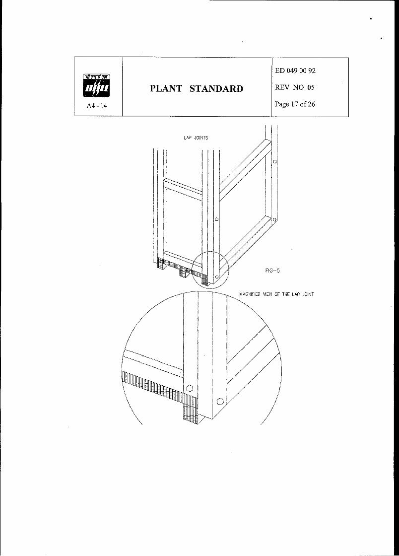
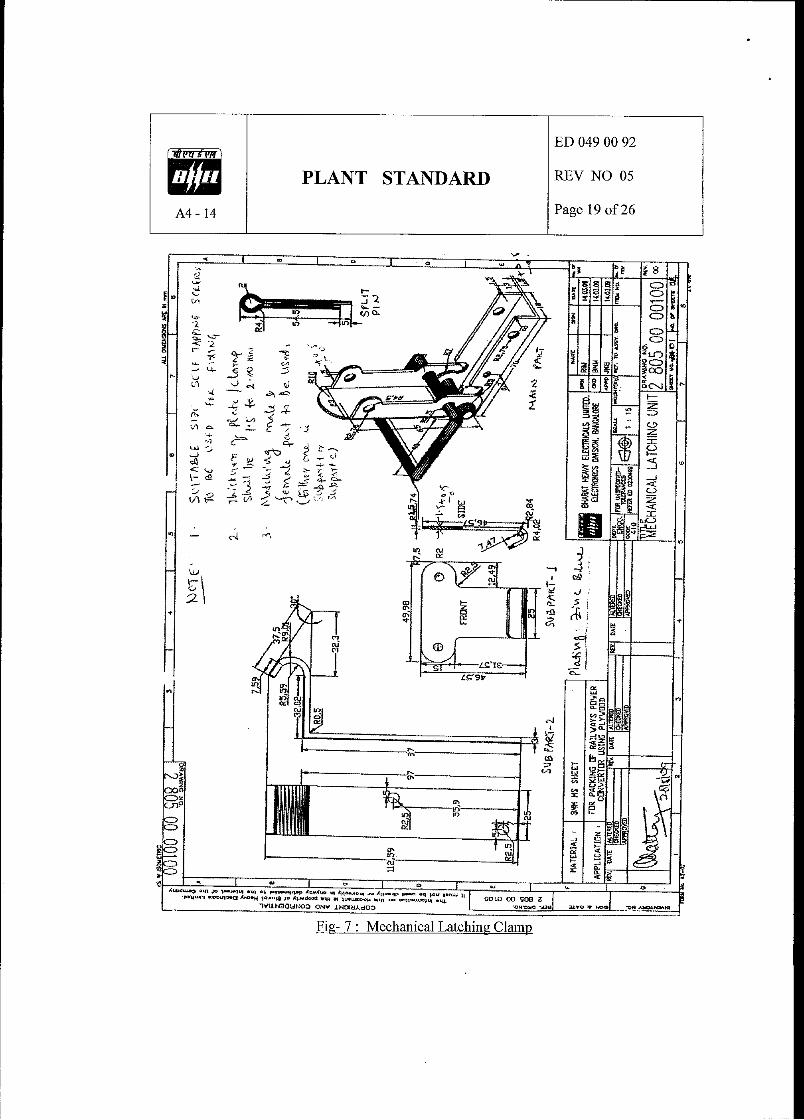
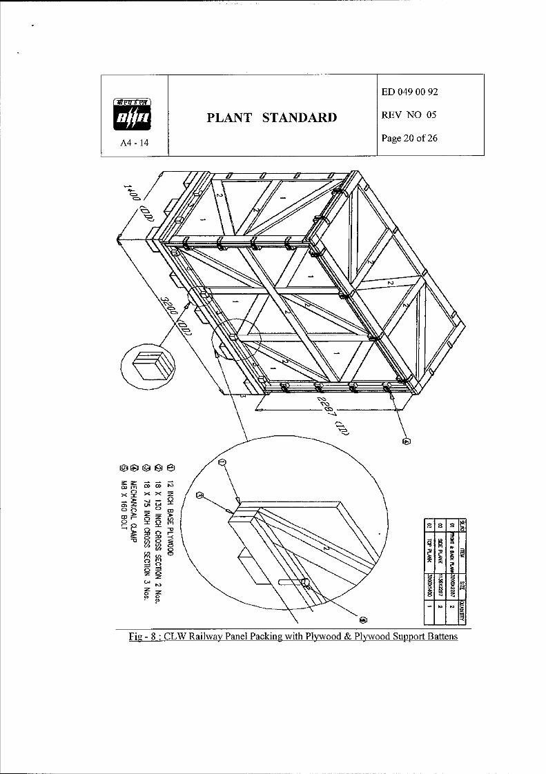
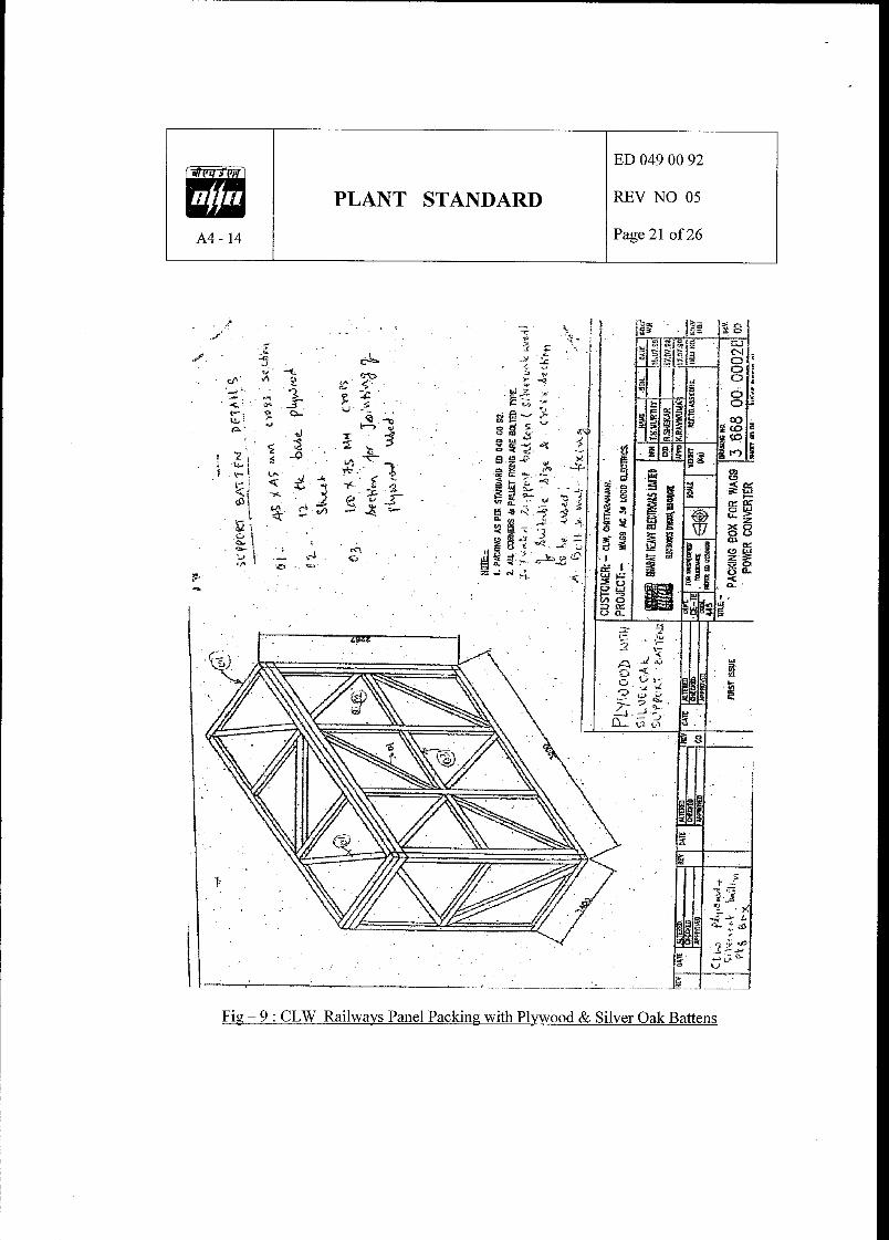
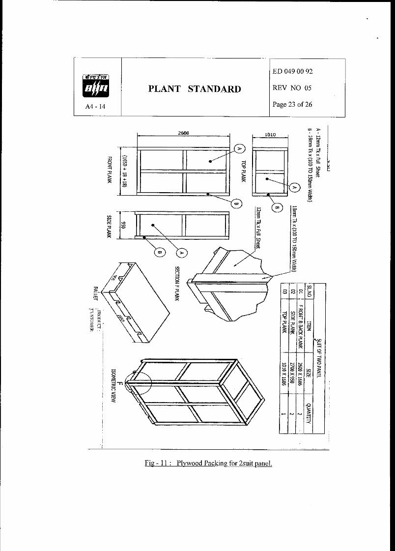
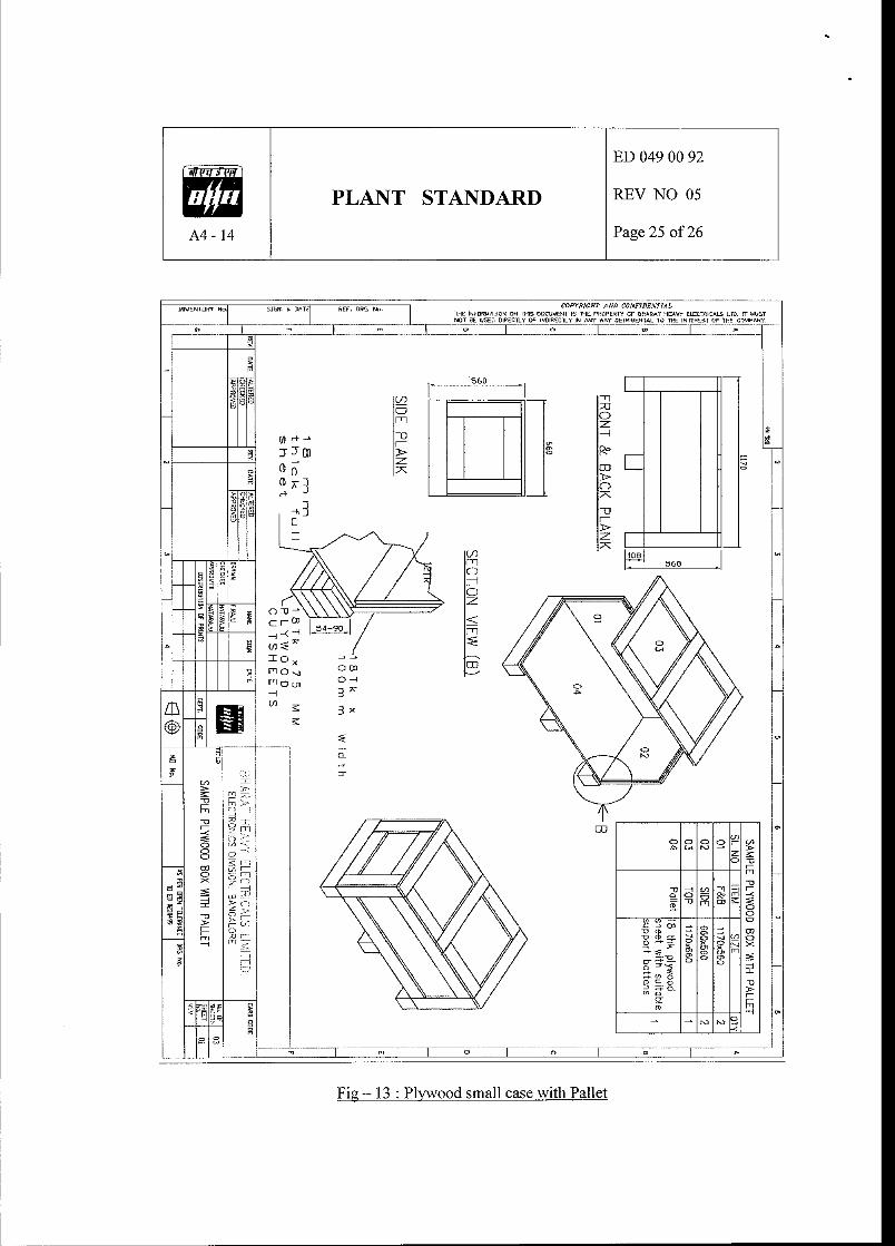
The detailed guideline for packaging is provided in specification reference ED 0490092, Rev. 05. The packing shall be separate for TSS & VMS, in separate boxes.
1.1 For Vibration sensors, Monitors, rack, special cable and signal conditioners being dispatched from OEM (countries other than India to India) packing which is suitable for transportation by Lorry and storage at site for extended periods up to 24 months, shall be used. For this a reference standard ED 490092 Rev 05 clause 3.1.2 is attached. OEMs shall follow this standard at minimum. If any other OEM standard packing is available same shall be submitted to BHEL for review and acceptance as part of Technical offer.
1.2 Imported items shall be packed in best fit boxes and total number of boxes per unit of TSS shall not exceed 1 box and for VMS shall not exceed 2 boxes.
1.3 For Panels, Server PC, Printer, Junction boxes, mounting pad / bracket, field cables etc
(i.e. typically from Indian manufacturers) packing which is suitable for transportation by Lorry and storage at site for extended periods up to 24 months, shall be used. For this a reference standard ED 490092 Rev 05 clause 3.1.1 is attached. OEMs shall follow this standard at minimum. If any other OEM standard packing is available same shall be submitted to BHEL for review and acceptance as part of Technical offer.
1.4 Indigenous items, except for bare panels & cables, shall be packed in best fit boxes and
total number of boxes per unit of TSS shall not exceed 2 box, for VMS shall not exceed 4 boxes and for Analysis & Diagnostics system shall not exceed 1 box.
1.5 Packing shall be separate for each unit of the project, TSS, VMS & Mandatory spares
separately.
1.6 Packing of the items shall be such that they can be repacked properly after material
verification at customs / site.


![[ Project Scope Management ] Requirement Specification Document for Purchase Management System](https://static.fdocuments.net/doc/165x107/56814167550346895dad44b1/-project-scope-management-requirement-specification-document-for-purchase.jpg)

