Pump Control Valve Model C601/CF601 - Flomatic Corp · DEEP WELL PUMP (TURBINE TYPE) Pump Control...
4
DEEP WELL PUMP (TURBINE TYPE) Pump Control Valve Model C601/CF601 Typical Applications BOOSTER PUMP (CENTRIFUGAL BOOSTER PUMP (TURBINE TYPE) The Model C601/CF601 Pump Control Valve protects against downstream pressure surges by placing the pump on line slowly and taking it off line slowly. When the pump starts, a three-way solenoid valve is energized to open the Pump Control Valve at a slow, controlled rate by discharging control water from above the diaphragm to waste through an adjustable needle valve. To shut down the pump, the three-way solenoid valve is de-energized to introduce control water above the diaphragm (through an adjustable needle valve) causing it to close slowly against the running pump.Just prior to full closure of the valve piston, the indicator rod opens a limit switch to stop the pump. SHALLOW LIFT PUMP (TURBINE TYPE) High Quality Valves Built to Last... www .flomatic.com
Transcript of Pump Control Valve Model C601/CF601 - Flomatic Corp · DEEP WELL PUMP (TURBINE TYPE) Pump Control...
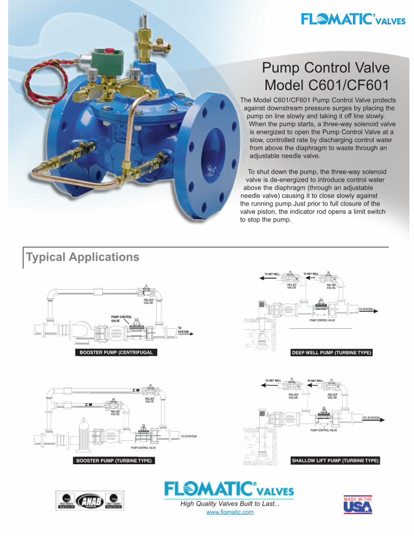
DEEP WELL PUMP (TURBINE TYPE)
Pump Control ValveModel C601/CF601
Typical Applications
BOOSTER PUMP (CENTRIFUGAL
BOOSTER PUMP (TURBINE TYPE)
The Model C601/CF601 Pump Control Valve protectsagainst downstream pressure surges by placing thepump on line slowly and taking it off line slowly. When the pump starts, a three-way solenoid valve is energized to open the Pump Control Valve at aslow, controlled rate by discharging control waterfrom above the diaphragm to waste through anadjustable needle valve.
To shut down the pump, the three-way solenoid valve is de-energized to introduce control water
above the diaphragm (through an adjustable needle valve) causing it to close slowly against the running pump.Just prior to full closure of the valve piston, the indicator rod opens a limit switch to stop the pump.
SHALLOW LIFT PUMP (TURBINE TYPE)
High Quality Valves Built to Last...www.flomatic.com
Temperature RatingSizes1 1/4” - 3” Threaded NPT / BSPP1 1/2” - 36” Flanged
Water up to 180o F (82oC)
2
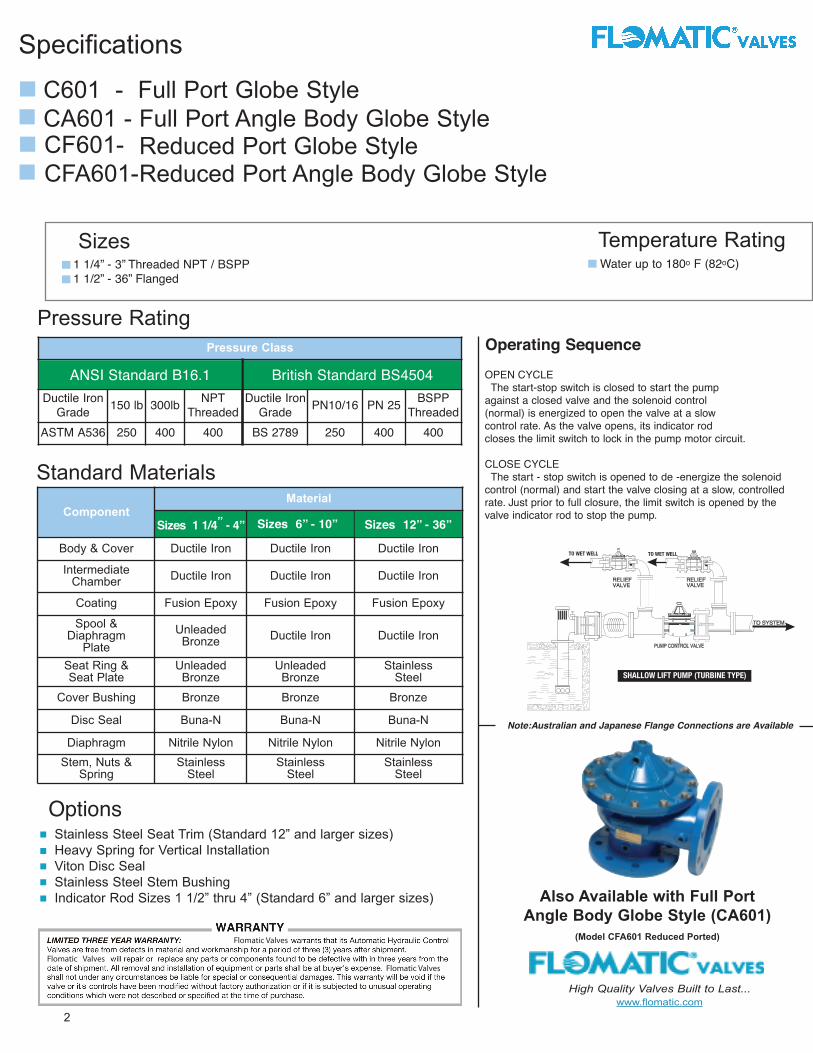
Also Available with Full PortAngle Body Globe Style (CA601)
(Model CFA601 Reduced Ported)
Operating Sequence
C601 - Full Port Globe Style CA601 - Full Port Angle Body Globe Style
High Quality Valves Built to Last...www.flomatic.com
Note:Australian and Japanese Flange Connections are Available
Pressure Rating
Stainless Steel Seat Trim (Standard 12” and larger sizes)Heavy Spring for Vertical InstallationViton Disc SealStainless Steel Stem BushingIndicator Rod Sizes 1 1/2” thru 4” (Standard 6” and larger sizes)
Pressure ClassANSI Standard
B16.1British Standard
BS4504Ductile Iron
Grade 150 lb 300lb NPTThreaded
Ductile IronGrade PN10/16 PN 25 BSPP
ThreadedASTM A536 250 400 400 BS 2789 250 400 400
Options
ANSI Standard B16.1 British Standard BS4504
CF601- CFA601-
Reduced Port Globe Style Reduced Port Angle Body Globe Style
Specifications
ComponentMaterial
Sizes6” - 10 “
Sizes1 1/4”-4”
Sizes12” - 36”
Body & Cover Ductile Iron Ductile Iron Ductile Iron
IntermediateChamber Ductile Iron Ductile Iron Ductile Iron
Coating Fusion Epoxy Fusion Epoxy Fusion Epoxy
Spool &Diaphragm
PlateUnleadedBronze Ductile Iron Ductile Iron
Seat Ring &Seat Plate
UnleadedBronze
UnleadedBronze
StainlessSteel
Cover Bushing Bronze Bronze Bronze
Disc Seal Buna-N Buna-N Buna-N
Diaphragm Nitrile Nylon Nitrile Nylon Nitrile NylonStem, Nuts &
SpringStainless
SteelStainless
SteelStainless
Steel
Standard Materials
Sizes12”- 36”Sizes 1 1/4” - 4” Sizes 12” - 36”Sizes 6” - 10”
OPEN CYCLEThe start-stop switch is closed to start the pump
against a closed valve and the solenoid control (normal) is energized to open the valve at a slow
Flomatic Valves
Flomatic ValvesFlomatic Valves
control rate. As the valve opens, its indicator rod closes the limit switch to lock in the pump motor circuit.
CLOSE CYCLEThe start - stop switch is opened to de -energize the solenoid
control (normal) and start the valve closing at a slow, controlledrate. Just prior to full closure, the limit switch is opened by the valve indicator rod to stop the pump.
3High Quality Valves Built to Last...www.flomatic.com
Va lve B odyType (S ize)
F low 1 . 5 ” 2 ” 2 . 5 ” 3 ” 4 ” 6 ” 8 ” 1 0 ” 1 2 ” 1 4 ” 1 6 ” 1 8 ” 2 0 ” 2 4 ” 3 0 ” 3 6 ”
M odel C & CAFull P or t ed
M odel CF & CFAR educedP or t ed
M odel C IDiaphr am
M in 2 . 5 4 7 1 1 2 0 4 0 8 0 1 2 0 1 8 0 2 4 0 3 0 0 4 0 0 5 0 0 7 0 0 1 , 0 0 0 -
Max 9 0 1 6 0 2 3 0 3 4 0 6 0 0 1 , 3 0 0 2 , 4 0 0 3 , 7 0 0 5 , 2 0 0 7 , 2 0 0 9 , 5 0 0 1 2 , 0 0 0 1 4 , 0 0 0 2 1 , 0 0 0 3 2 , 0 0 0 -
M in - - - 7 1 1 3 0 4 0 8 0 1 2 0 1 8 0 2 4 0 3 0 0 4 0 0 5 0 0 7 0 0 9 0 0
Max - - - 1 6 0 3 4 0 6 0 0 1 , 3 0 0 2 , 4 0 0 3 , 7 0 0 5 , 2 0 0 7 , 2 0 0 9 , 5 0 0 1 2 , 0 0 0 1 4 , 0 0 0 2 1 , 0 0 0 3 2 , 0 0 0
M in - 2 2 2 5 8 2 5 - - - - - - - - -
M ax - 1 1 0 1 3 2 1 3 2 2 6 4 1 , 0 2 0 1 , 7 9 0 - - - - - - - - -
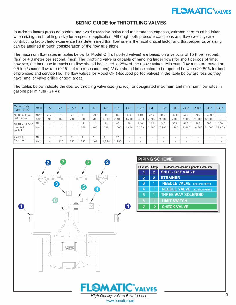
SIZING GUIDE for THROTTLING VALVES
In order to insure pressure control and avoid excessive noise and maintenance expense, extreme care must be takenwhen sizing the throttling valve for a specific application. Although both pressure conditions and flow (velocity) arecontributing factor, field experience has determined that flow rate is the most critical factor and that proper valve sizingcan be attained through consideration of the flow rate alone.
The maximum flow rates in tables below for Model C (Full ported valves) are based on a velocity of 15 ft per second,(fps) or 4.6 meter per second, (m/s). The throttling valve is capable of handling larger flows for short periods of time;however, the increase in maximum flow should be limited to 25% of the above values. Minimum flow rates are based on0.5 feet/second flow rate (0.15 meter per second, m/s). Valve should be selected to be opened between 20-80% for bestefficiencies and service life. The flow values for Model CF (Reduced ported valves) in the table below are less as theyhave smaller valve orifice or seat areas.
The tables below indicate the desired throttling valve size (inches) for designated maximum and minimum flow rates ingallons per minute (GPM):
Bulletin No.C601/CF601 11/23/05
C
High Quality Valves Built to Last...www.flomatic.com
4
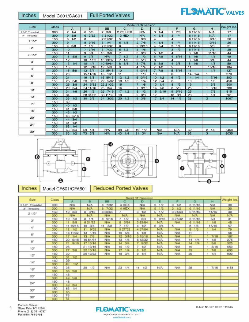
Inches Model C201/CF201 Full Ported Valves
A B BB C D E F G H1 1/2" Threaded 300 7 1/4 6 5/8 7 3/8 2 7/8 HEX N/A 3 1/4 1 7/8 6 11/16 N/A 172" Threaded 300 9 3/8 6 13/32 7 31/32 3 HEX N/A 4 3/4 3 1/4 6 11/16 N/A 17
150 8 1/2 8 7 31/32 5 2 3/8 4 4 6 11/16 9/16 20300 9 8 9/16 8 1/4 6 1/8 2 7/8 4 1/4 4 1/4 6 11/16 13/16 26150 9 3/8 7 1/2 7 31/32 6 2 13/16 4 3/4 3 1/4 6 11/16 5/8 21300 10 7 13/16 8 7/32 6 1/2 3 1/8 5 3 1/2 6 11/16 7/8 28150 11 9 3/4 10 3/8 7 3 3/8 5 1/2 4 8 1/8 11/16 44300 11 5/8 9 7/8 N/A 7 1/2 3 1/2 5 7/8 4 5/16 8 1/8 1 1/8 49150 12 10 1/32 10 13/32 7 1/2 3 5/8 6 4 8 1/8 3/4 44300 13 1/4 10 1/4 10 49/64 8 1/4 3 7/8 6 3/8 4 3/8 8 1/8 1 1/8 59150 15 12 3/16 12 5/8 9 4 1/4 7 1/2 5 11 15/16 104300 15 5/8 12 3/4 21 15/16 10 4 13/16 7 7/8 5 5/16 11 1 1/4 127150 20 15 11/16 16 1/2 11 5 1/8 10 6 14 1/4 1 270300 21 16 3/8 16 15/16 12 1/2 5 13/16 10 1/2 6 1/2 14 1/4 1 7/16 303150 25 3/8 23 9/32 22 5/32 13 1/2 6 1/4 12 3/4 8 19 1 1/8 450300 26 3/8 24 5/32 22 21/32 15 7 1/8 13 1/4 8 1/2 19 1 5/8 500150 29 3/4 24 11/16 25 3/4 16 7 9/16 14 7/8 8 5/8 25 1 3/16 780300 31 1/8 26 1/2 26 7/16 17 1/2 8 1/2 15 9/16 9 5/16 25 1 7/8 815150 34 28 31/32 33 11/32 19 9 3/8 17 13 3/4 28 1 1/4 761300 35 1/2 30 3/8 34 3/32 20 1/2 9 3/8 17 3/4 14 1/2 28 2 1067150 39300 40 1/2150 41 3/8300 43 1/2150 43 5/16300 44 3/4150 61 1/2300 63 1/4150 63 3/4 69 1/4 N/A 38 7/8 19 1/2 N/A N/A 62 2 1/8 7468300 65 1/2 73 5/8 N/A 43 1/4 21 3/4 N/A N/A 62 3 8035
1 1/2"
6"
8"
10"
12"
2"
2 1/2"
3"
4"
Size Class Model C Dimension Weight lbs.
30"
14"
16"
20"
24"
Model C601/CA601
Model CF601/CFA601
F
B
A
C
D
H
GBB
F
C
E
D
Flomatic ValvesGlens Falls, NY 12801Phone (518) 761-9797Fax (518) 761-9798