Pulsed Fiber Laser Presentation
27
High Power Pulsed Fiber Lasers Colin Diehl, Yevgeniy Krasnitskiy, Doug Lyons, Jered Richter
-
Upload
yevgeniy-krasnitskiy -
Category
Documents
-
view
556 -
download
3
Transcript of Pulsed Fiber Laser Presentation
High Power Pulsed
Fiber Lasers
Colin Diehl, Yevgeniy Krasnitskiy, Doug Lyons, Jered Richter
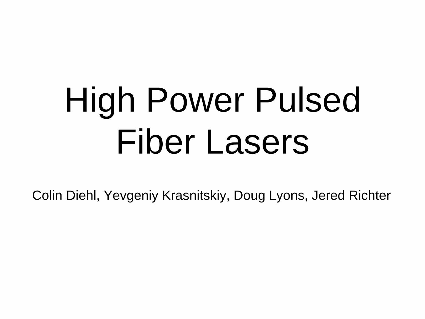
Basic Components of
Lasers• Power Source
• Gain Medium
• Feedback
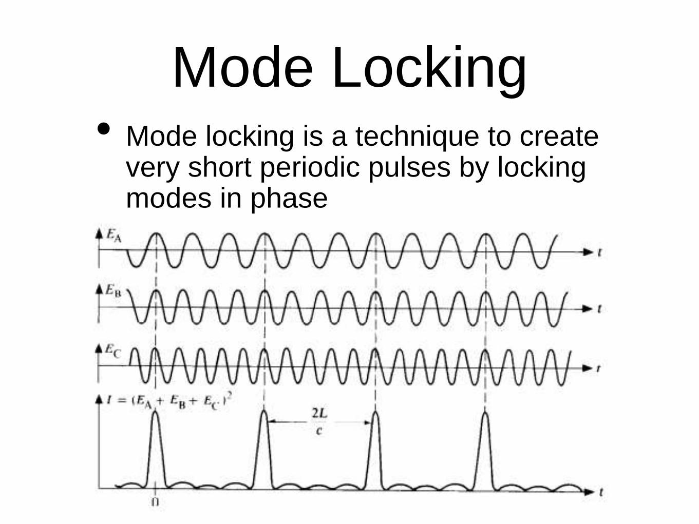
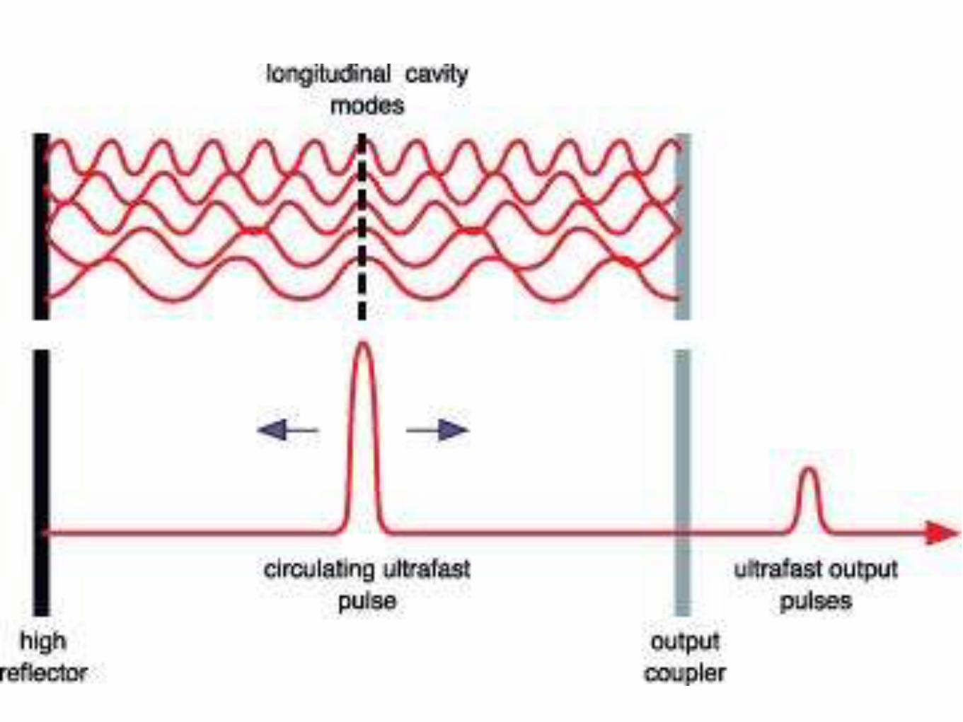
Mode Locking• Mode locking is a technique to create
very short periodic pulses by locking modes in phase
Additive-pulse Mode
Locking• Nonlinear phase shifts in a single-mode fiber.
• Pulses returning from the fiber resonator into the
main laser resonator interfere with those pulses
which already are in the main resonator.
• Constructive interference near the peak of the
pulses, but not in the wings, because the latter have
acquired different nonlinear phase shifts in the fiber.
• Peak of the circulating pulse is enhanced, whereas
the wings are attenuated.
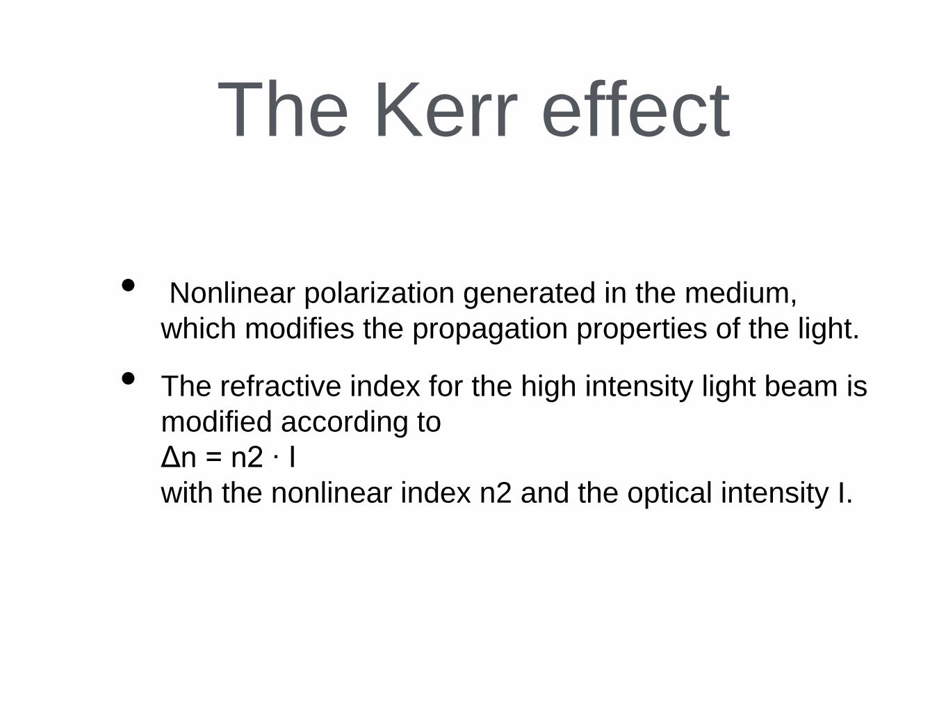
The Kerr effect
• Nonlinear polarization generated in the medium,
which modifies the propagation properties of the light.
• The refractive index for the high intensity light beam is
modified according to
Δn = n2 ∙ I
with the nonlinear index n2 and the optical intensity I.
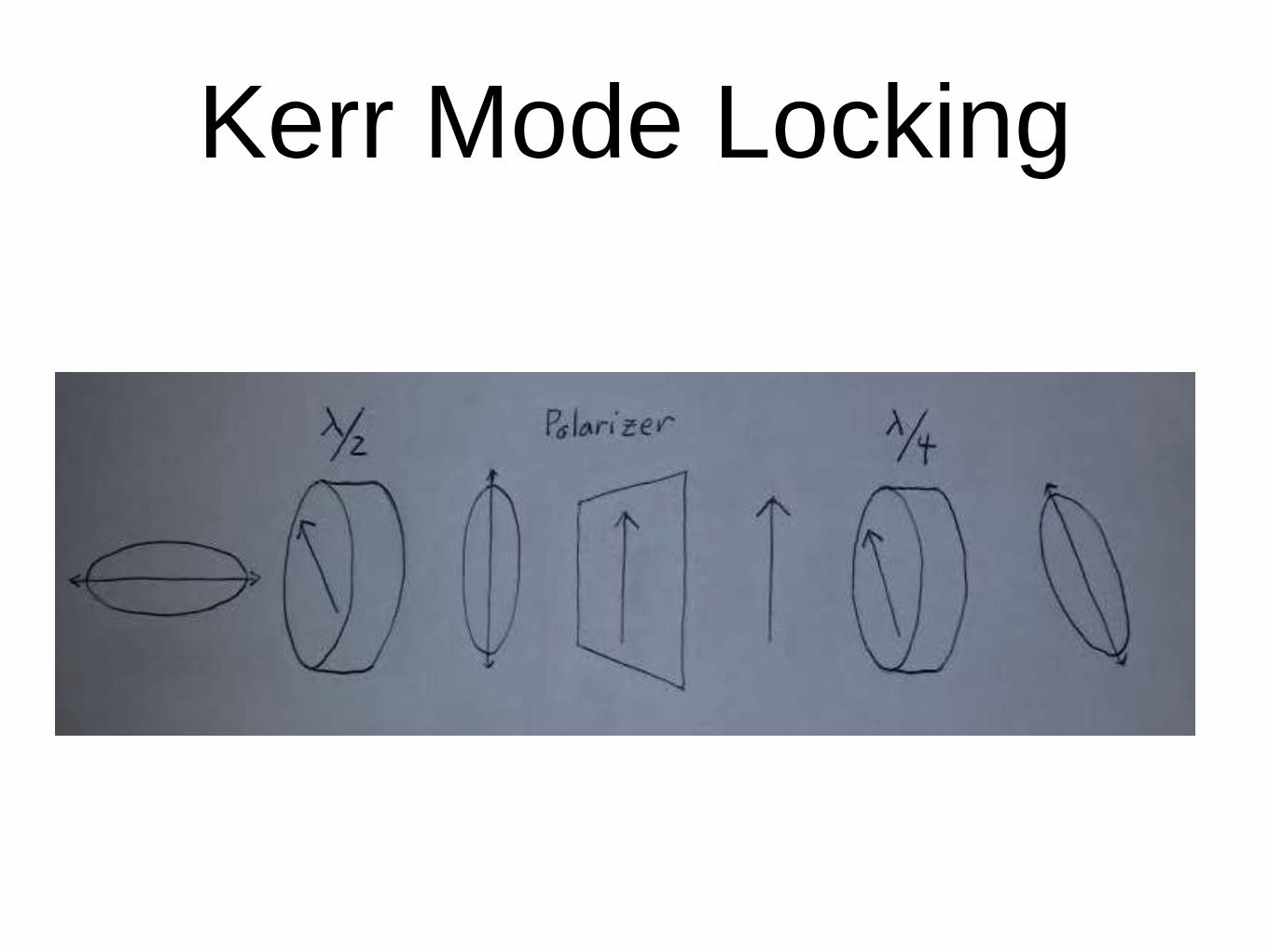
Kerr Mode Locking
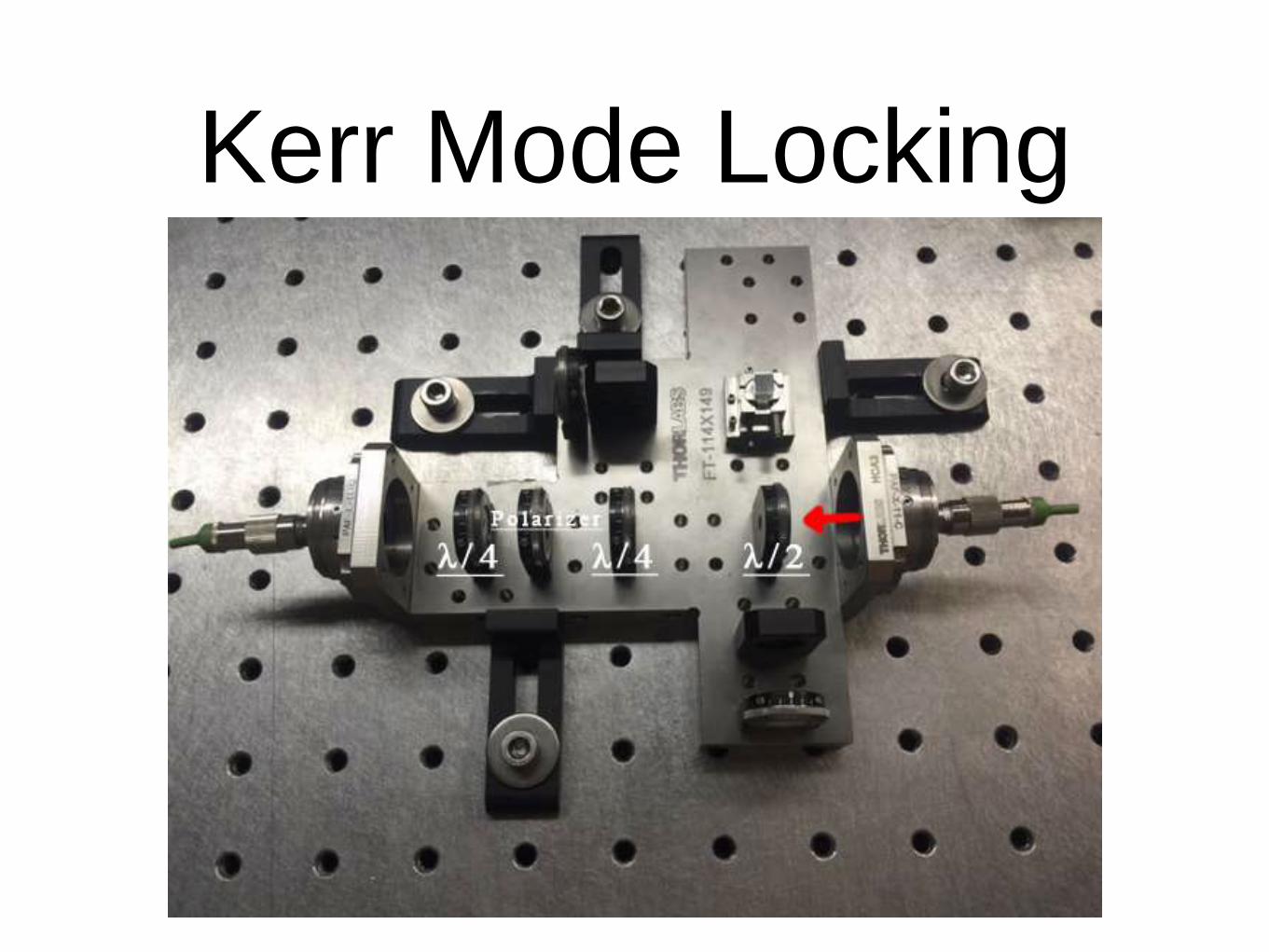
Kerr Mode Locking
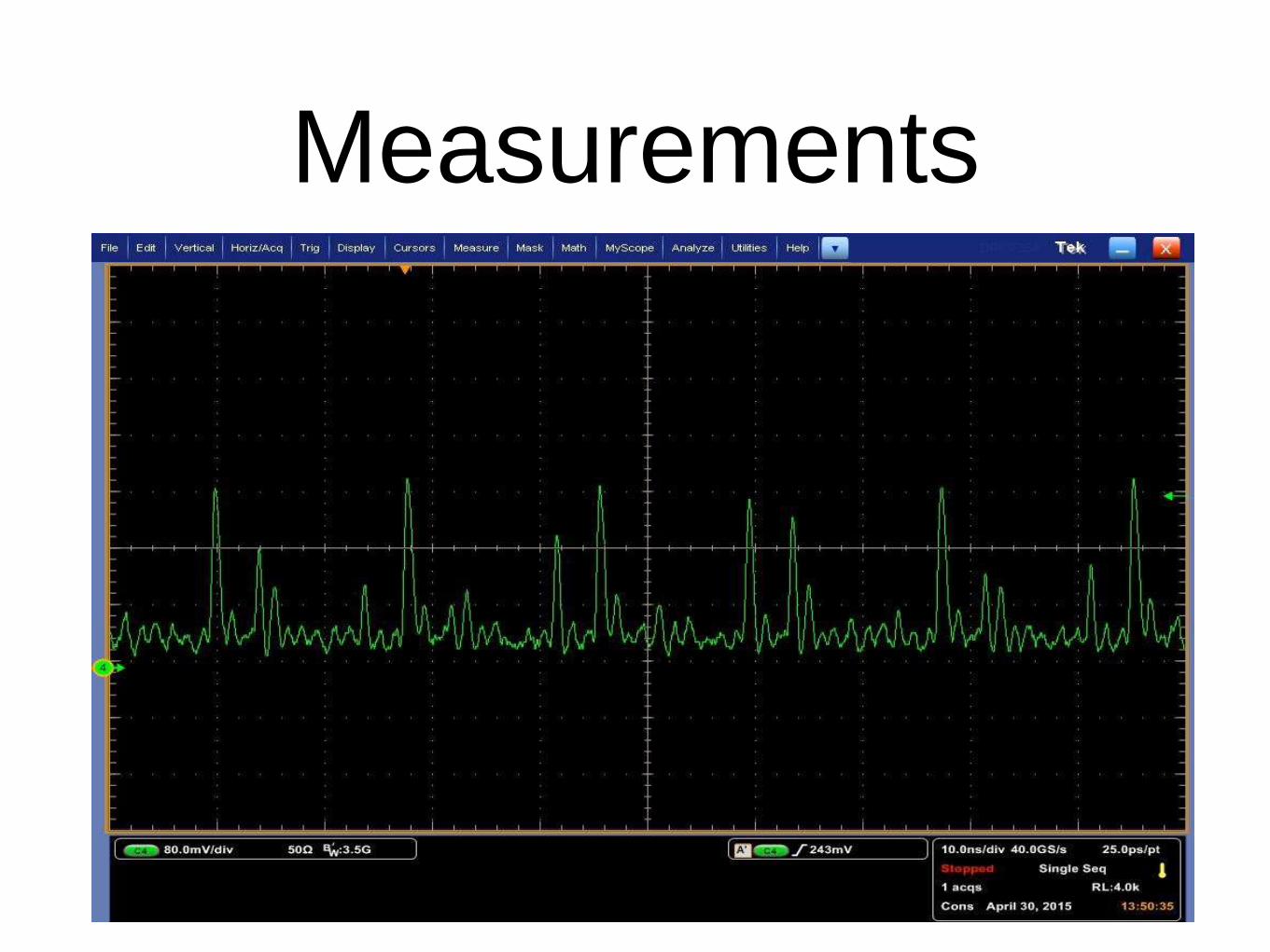
Measurements
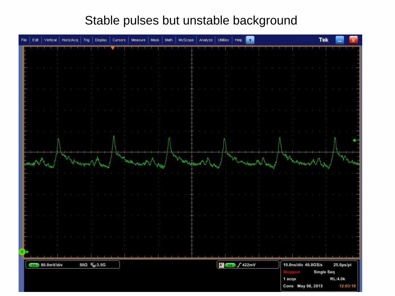
Stable pulses but unstable background
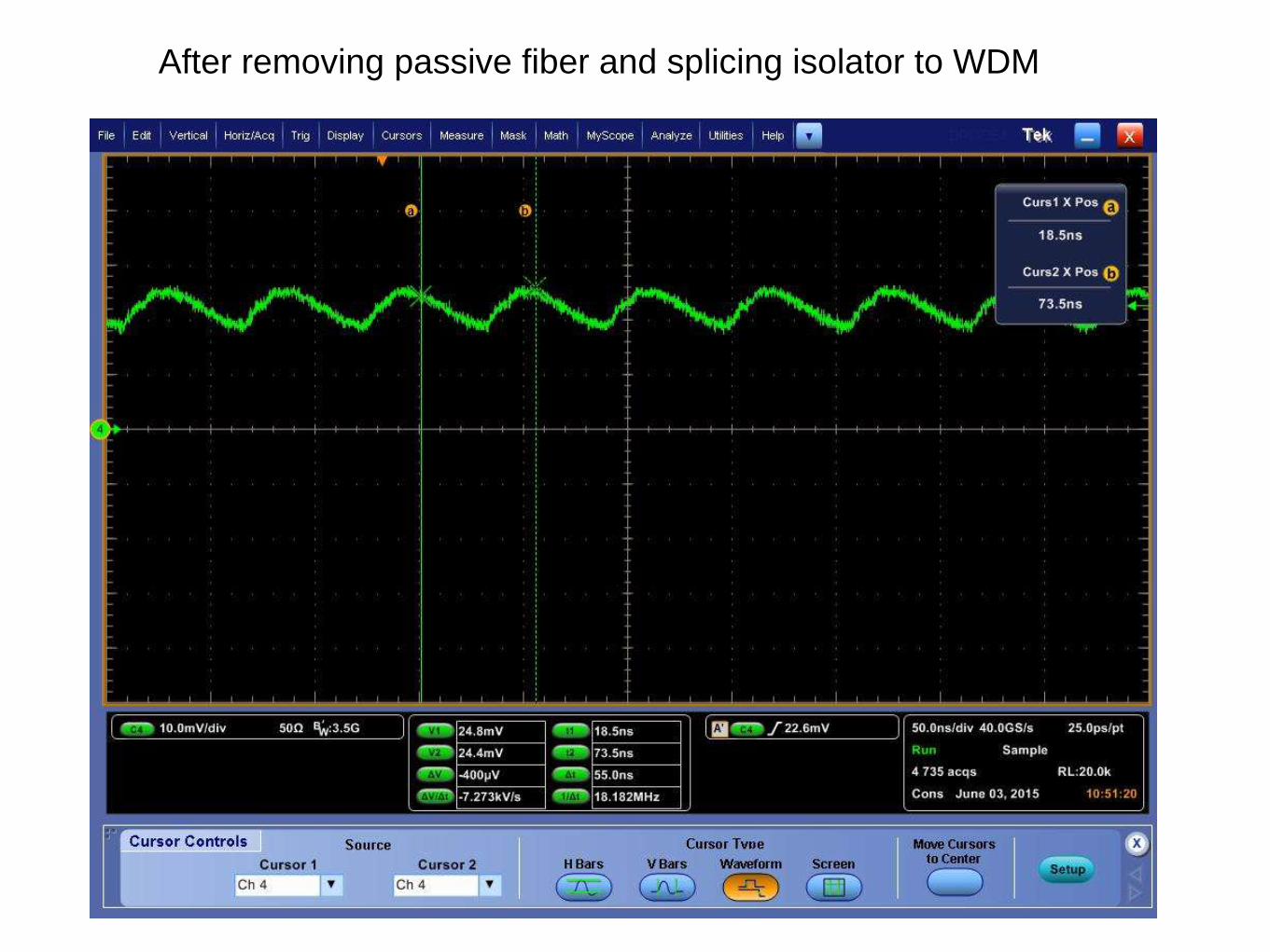
After removing passive fiber and splicing isolator to WDM
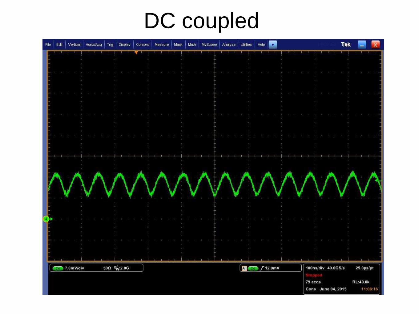
DC coupled
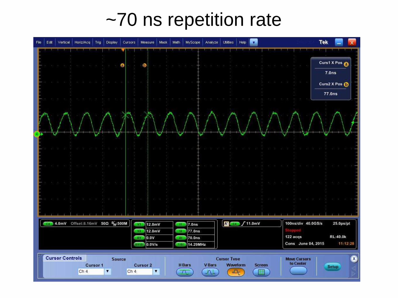
~70 ns repetition rate
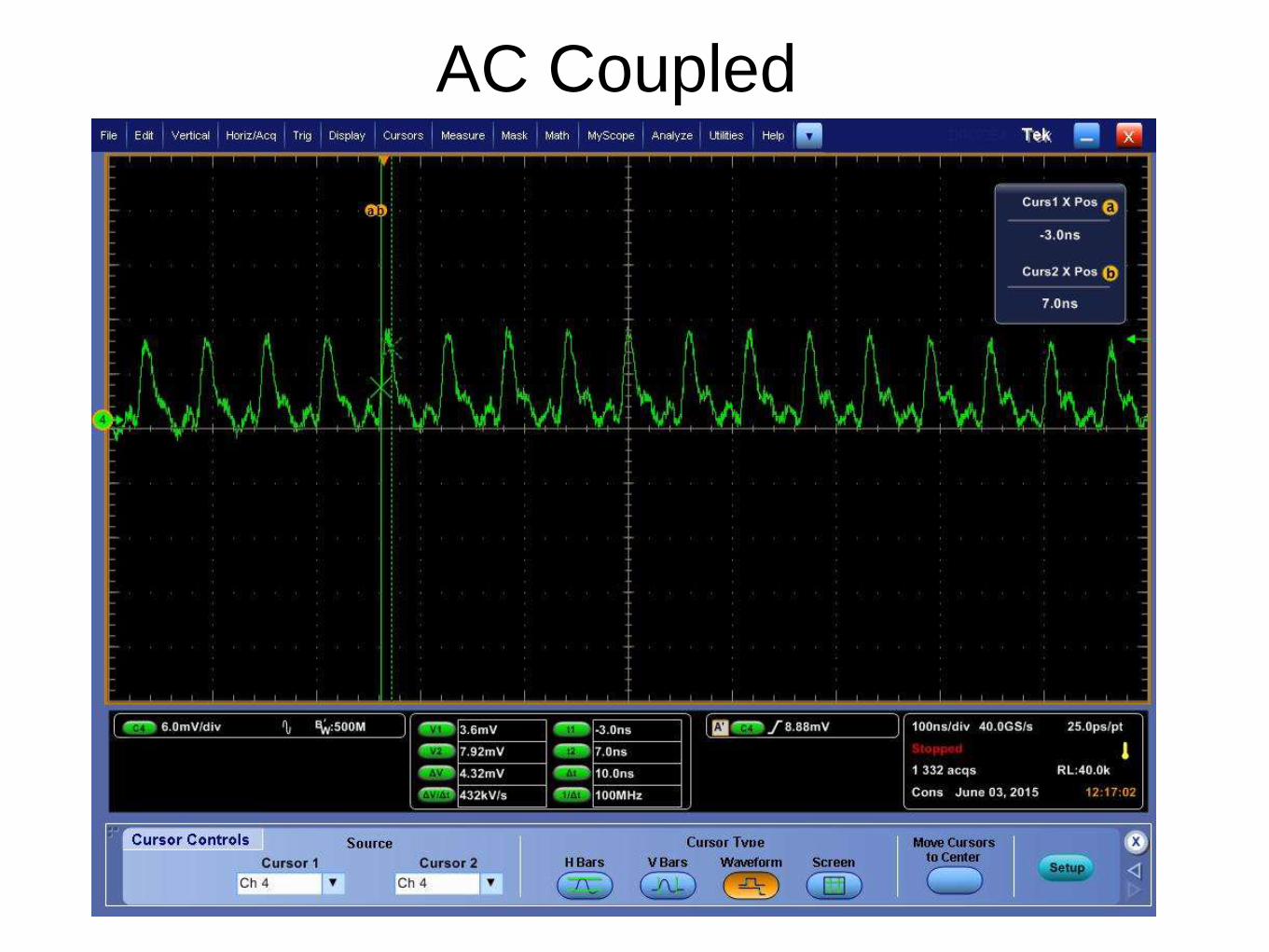
AC Coupled
WDM Problems
• Single-mode pigtail of WDM broke, too
small to be re-spliced
• Unprotected fusion splice of double-clad to
single-mode caused coating to burn
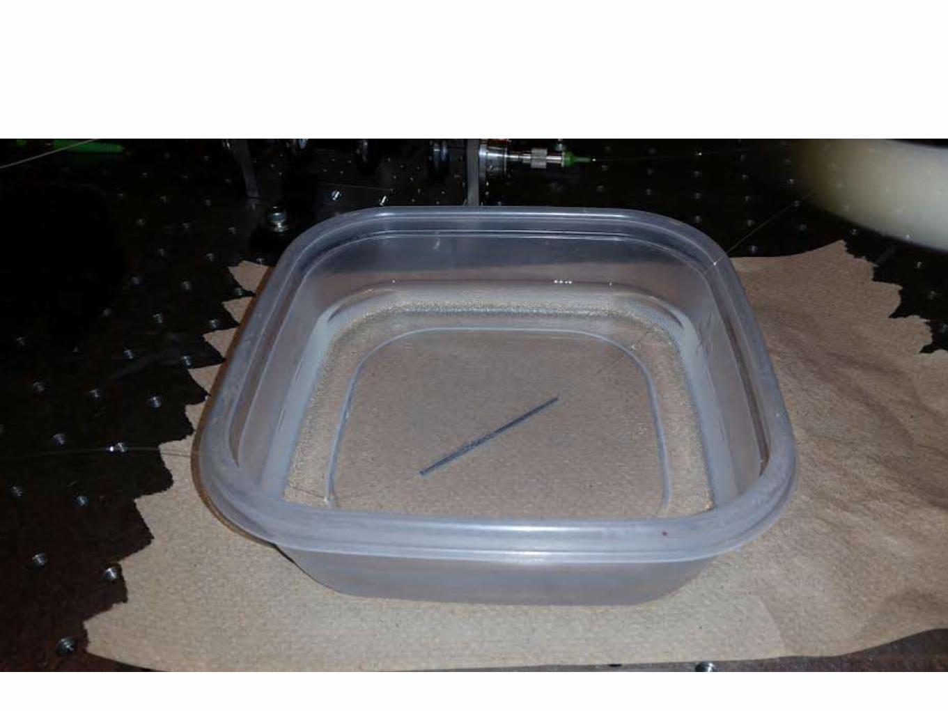
• Splice protector submerged in water
stopped burning, cooled splice

MOPA (Master Oscillator
Power Amplifier)• This fiber laser will consist of three
stages:
• 1st: Master Oscillator (this is the
stage that will contain the
graphene and will produce the
pulsing)
• 2nd: Single-Mode Power Amplifier
• 3rd: Double-Clad Power Amplifier

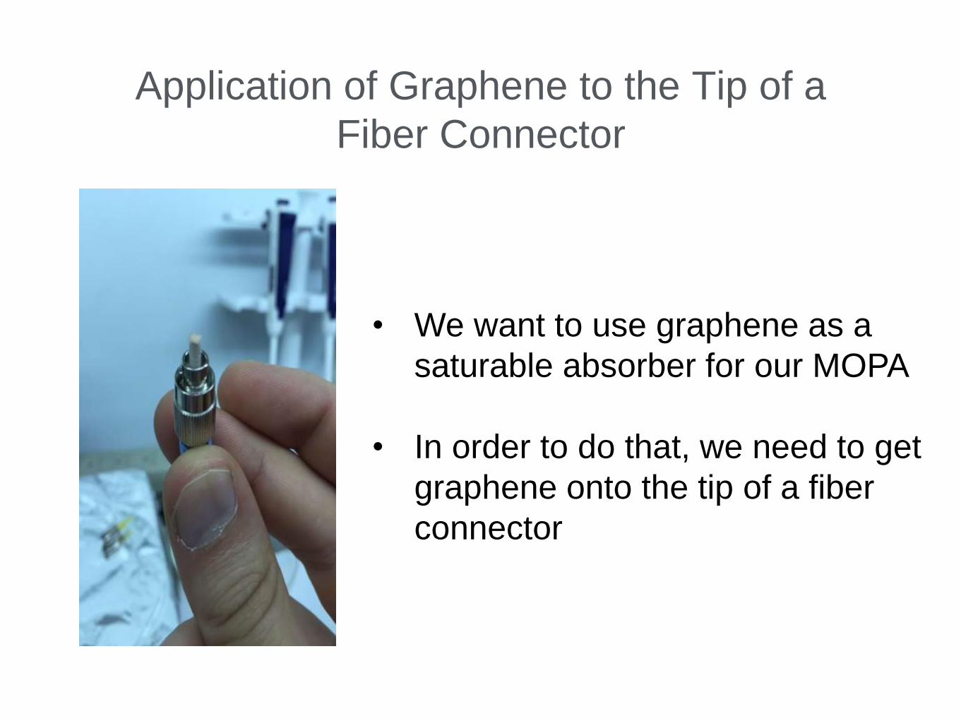
Application of Graphene to the Tip of a
Fiber Connector
• We want to use graphene as a
saturable absorber for our MOPA
• In order to do that, we need to get
graphene onto the tip of a fiber
connector
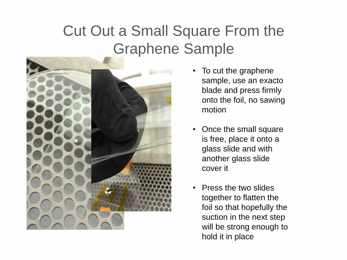
Cut Out a Small Square From the
Graphene Sample
• To cut the graphene
sample, use an exacto
blade and press firmly
onto the foil, no sawing
motion
• Once the small square
is free, place it onto a
glass slide and with
another glass slide
cover it
• Press the two slides
together to flatten the
foil so that hopefully the
suction in the next step
will be strong enough to
hold it in place
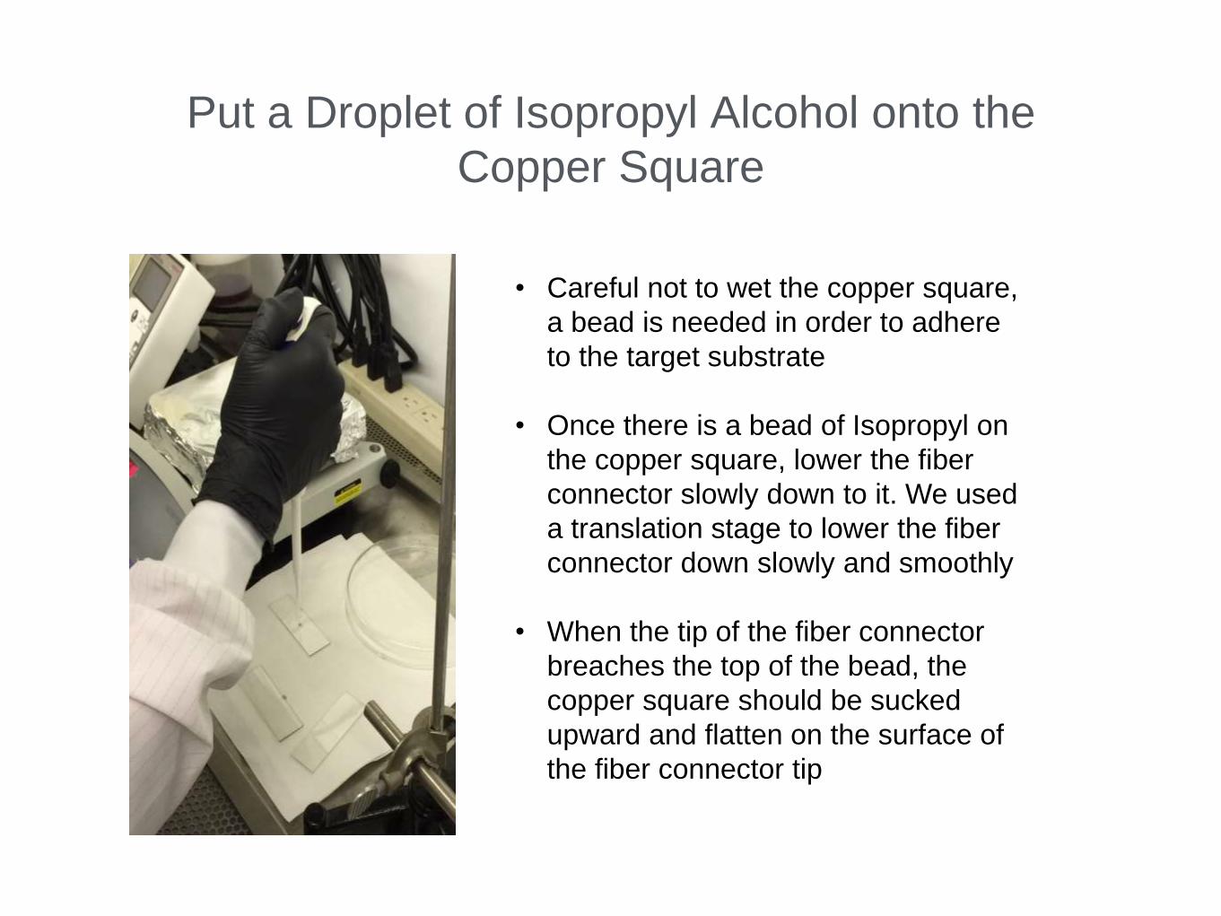
Put a Droplet of Isopropyl Alcohol onto the
Copper Square
• Careful not to wet the copper square,
a bead is needed in order to adhere
to the target substrate
• Once there is a bead of Isopropyl on
the copper square, lower the fiber
connector slowly down to it. We used
a translation stage to lower the fiber
connector down slowly and smoothly
• When the tip of the fiber connector
breaches the top of the bead, the
copper square should be sucked
upward and flatten on the surface of
the fiber connector tip
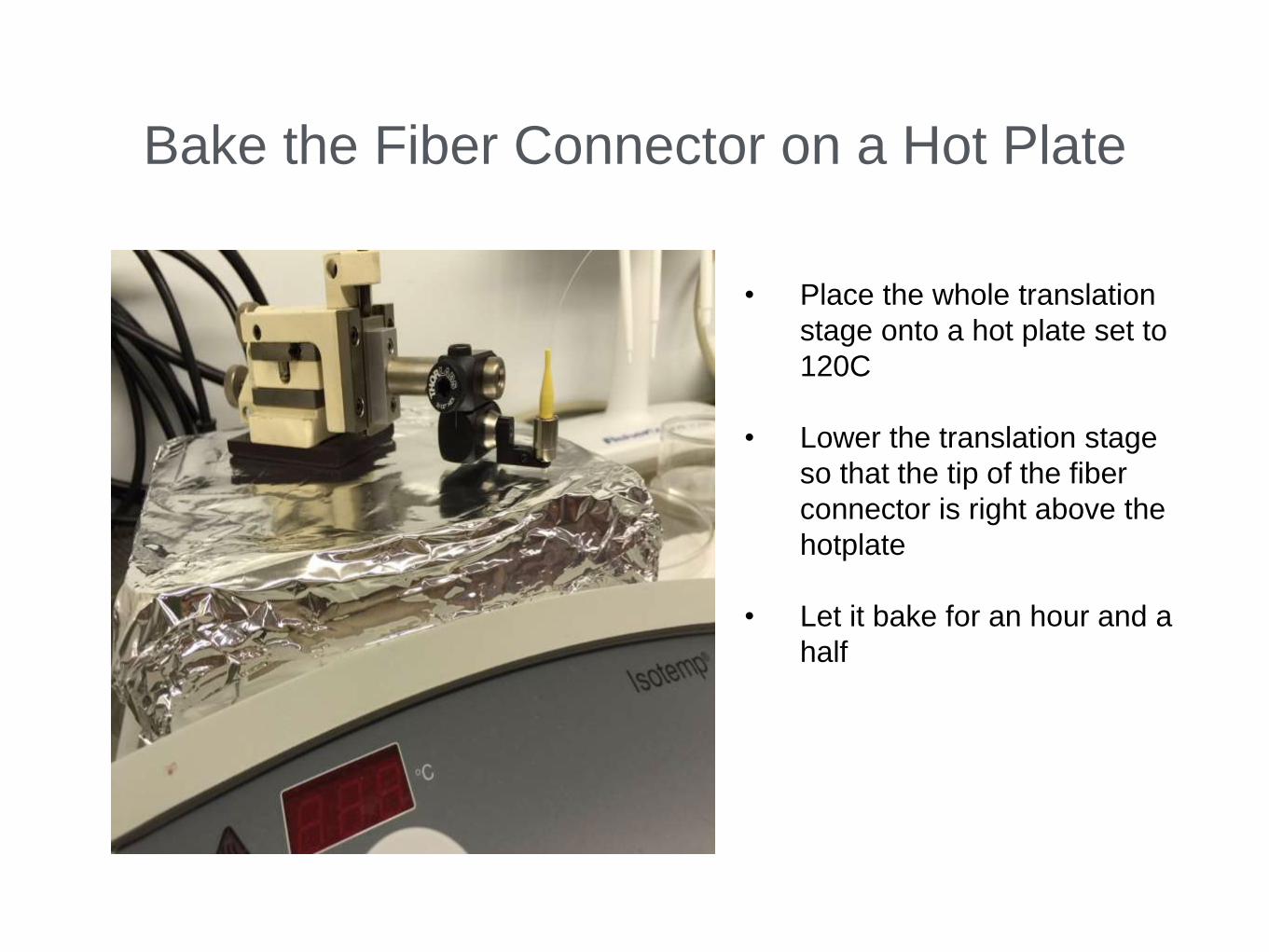
Bake the Fiber Connector on a Hot Plate
• Place the whole translation
stage onto a hot plate set to
120C
• Lower the translation stage
so that the tip of the fiber
connector is right above the
hotplate
• Let it bake for an hour and a
half
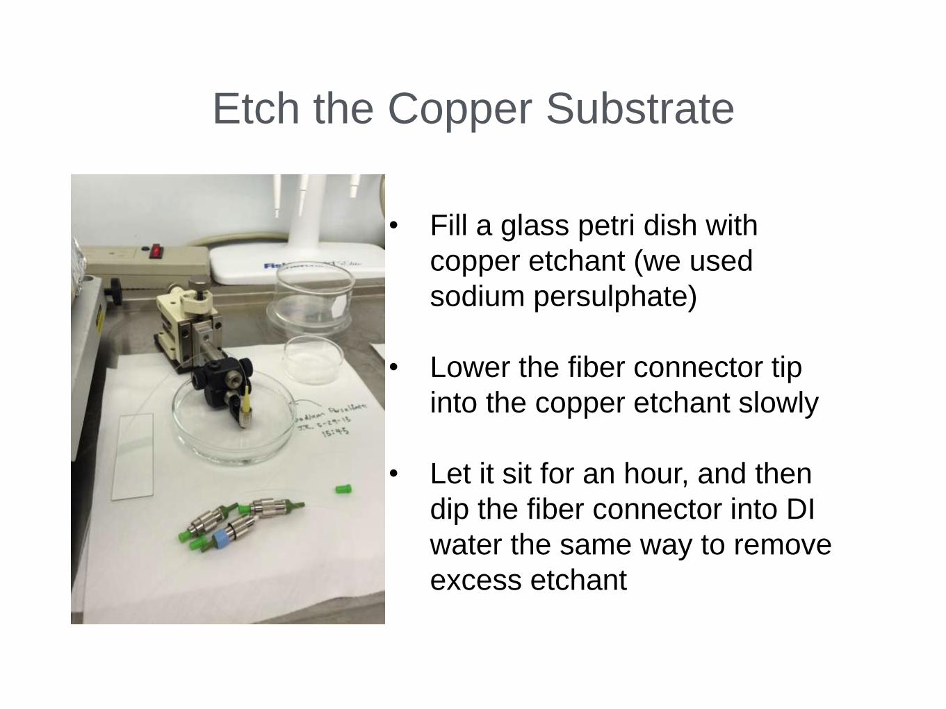
Etch the Copper Substrate
• Fill a glass petri dish with
copper etchant (we used
sodium persulphate)
• Lower the fiber connector tip
into the copper etchant slowly
• Let it sit for an hour, and then
dip the fiber connector into DI
water the same way to remove
excess etchant

Attempts at Imaging Graphene on the Tip
of the Fiber Connector