
Pulse Burst Radar Level Transmitters
8
LEVEL TRANSMITTERS PULSE BURST RADAR LEVEL TRANSMITTERS K-BAND RADAR FOR LIQUIDS 3 YeaRs WaRRantY PiloTREK Arjay Automation, Inc. Burnsville, MN USA (800) 761-1749 www.arjaynet.com
-
Upload
arjay-automation -
Category
Engineering
-
view
49 -
download
3
Transcript of Pulse Burst Radar Level Transmitters

SZIN
TTÁ
VAD
ÓK
LEVE
L TR
AN
SMIT
TERS
PULSE BURST R ADAR LEVEL TR ANSMIT TERSK- BAND R ADAR FOR L IQUIDS
3 Ye
aRs
Wa
RRa
ntY
PiloTREKArjay Automation, Inc.Burnsville, MN USA(800) 761-1749www.arjaynet.com
MAIN FEATURES ■ 2-wire K-band Pulse Burst Radar ■ 25 GHz frequency ■ Max. 23 m (75 feet) measuring range
for liquids and slurries ■ ±3 mm (0.12 inch) accuracy ■ Easy installation due to small antennas ■ Parabolic, horn, planar and enclosed antenna types ■ IP68 rated integrated type ■ Sanitary types for meeting high hygienic requirements ■ High temperature version ■ Plug-in graphical display module ■ Ex version
INDUSTRY SEGMENTS ■ Water, wastewater ■ Power generation ■ Food and beverage ■ Pharmaceutical ■ Chemical
APPLICATIONS ■ Level measurement of liquids, slurries, emulsions
and other chemicals up to 23 m (75 feet) ■ For mid / large-size vessels, chemical tanks ■ Level measurement through plastic tank wall
GENER AL DESCRIPTIONThe 25 GHz (K-band) PiloTREK Pulse Radars are regarded as the most progressive non-contact level transmitters of the industrial process automation field. Their accuracies are excellent and their short and narrow antennas make their installation simple and low cost. NIVELCO’s K-band radar featuring ±3 mm (0.12 inch) accuracy and short dead band excels with its versatile housing concept lining up plastic, aluminium and stainless steel versions. Its antenna range incorporates stainless steel horn or parabolic planar antenna and enclosed plastic tube varieties. The enclosed antenna versions can be replaced without removing the antenna enclosure from the process. Local programming of the PiloTREK is aided by a plug-in display module. If on-site reading is not desired this module may not be required thus reducing cost of ownership. The signal processing algorithm of the PiloTREK is based on NIVELCO’s 35 years of experience with non-contact level measurement making it an excellent choice for applications simple and challenging alike.
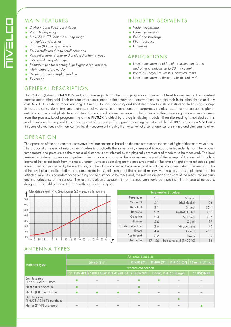
OPER ATIONThe operation of the non-contact microwave level transmitters is based on the measurement of the time of flight of the microwave burst. The propagation speed of microwave impulses is practically the same in air, gases and in vacuum, independently from the process temperature and pressure, so the measured distance is not affected by the physical parameters of medium to be measured. The level transmitter induces microwave impulses a few nanosecond long in the antenna and a part of the energy of the emitted signals is bounced (reflected) back from the measurement surface depending on the measured media. The time of flight of the reflected signal is measured and processed by the electronics, and then this is converted to distance, level or volume proportional data. The measurability of the level of a specific medium is depending on the signal strength of the reflected microwave impulses. The signal strength of the reflected impulses is considerably depending on the distance to be measured, the relative dielectric constant of the measured medium and the turbulence of the surface. The relative dielectric constant (er) of the medium should be more than 1.4 in case of parabolic design, or it should be more than 1.9 with horn antenna types.
Informative er valuesPetroleum 2.1 Acetone 21Crude oil 2.1 Ethyl alcohol 24Diesel oil 2.1 Ethanol 25.1Benzene 2.2 Methyl alcohol 33.1
Gasoline 2.3 Methanol 33.7Bitumen 2.6 Glycol 37
Carbon disulfide 2.6 Nitrobenzene 40Ethers 4.4 Glycerol 41.1
Acetic acid 6.2 Water 80Ammonia 17 – 26 Sulphuric acid (T=20 °C) 84
Antenna type
Antenna diameter
DN40 (1½") DN50 (2") DN80 (3") DN150 (6") 48 mm (1.9 inch)
Process connection
1½" BSP/NPT 2" TRICLAMP DN50 MILCH 2" BSP/NPT DN80, DN150 flanges 2" BSP/NPTStainless steel (1.4571 / 316 Ti) horn
Plastic (PP) enclosure
Plastic (PTFE) enclosure
Stainless steel (1.4571 / 316 Ti) parabolic
Planar 2" (PP) enclosure
ANTENNA T YPES
Reflected signal strength (%) vs. Dielectric constant (er) compared to a flat metal plate
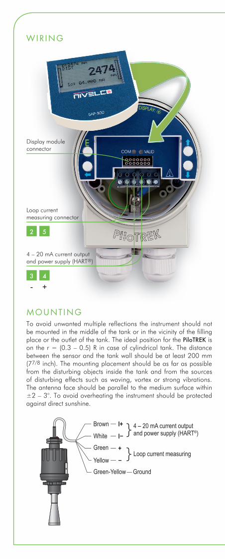
MOUNTINGTo avoid unwanted multiple reflections the instrument should not be mounted in the middle of the tank or in the vicinity of the filling place or the outlet of the tank. The ideal position for the PiloTREK is on the r = (0.3 – 0.5) R in case of cylindrical tank. The distance between the sensor and the tank wall should be at least 200 mm (77/8 inch). The mounting placement should be as far as possible from the disturbing objects inside the tank and from the sources of disturbing effects such as waving, vortex or strong vibrations. The antenna face should be parallel to the medium surface within ±2 – 3°. To avoid overheating the instrument should be protected against direct sunshine.
Loop current measuring connector
2 5
3 4
-
Display moduleconnector
4 – 20 mA current output and power supply (HART®)
+
WIRING
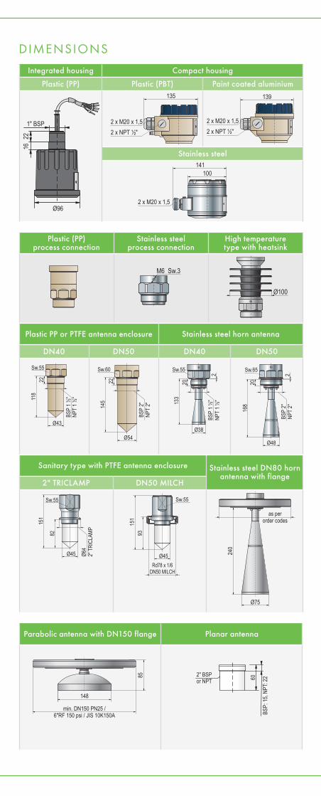
DIMENSIONS
Integrated housing Compact housing
Plastic (PP) Plastic (PBT) Paint coated aluminium
Stainless steel
Ø96
1" BSP
22
16
Sanitary type with PTFE antenna enclosure Stainless steel DN80 horn antenna with flange
2" TRICLAMP DN50 MILCH
Plastic (PP)process connection
Stainless steelprocess connection
High temperature type with heatsink
Plastic PP or PTFE antenna enclosure Stainless steel horn antenna
DN40 DN50 DN40 DN50
Parabolic antenna with DN150 flange Planar antenna
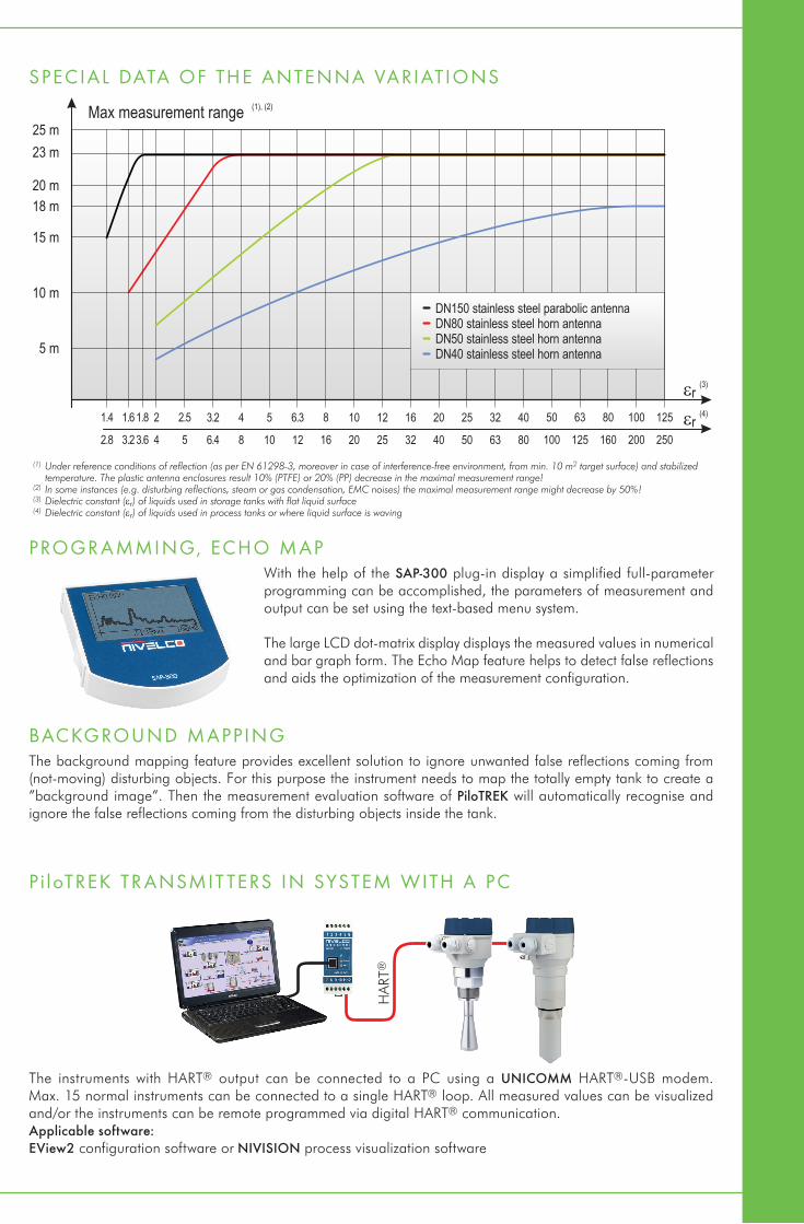
SPECIAL DATA OF THE ANTENNA VARIATIONS
(1) Under reference conditions of reflection (as per EN 61298-3, moreover in case of interference-free environment, from min. 10 m2 target surface) and stabilized temperature. The plastic antenna enclosures result 10% (PTFE) or 20% (PP) decrease in the maximal measurement range!
(2) In some instances (e.g. disturbing reflections, steam or gas condensation, EMC noises) the maximal measurement range might decrease by 50% !(3) Dielectric constant (er) of liquids used in storage tanks with flat liquid surface(4) Dielectric constant (er) of liquids used in process tanks or where liquid surface is waving
PROGR AMMING, ECHO MAPWith the help of the SAP-300 plug-in display a simplified full-parameter programming can be accomplished, the parameters of measurement and output can be set using the text-based menu system.
The large LCD dot-matrix display displays the measured values in numerical and bar graph form. The Echo Map feature helps to detect false reflections and aids the optimization of the measurement configuration.
BACKGROUND MAPPINGThe background mapping feature provides excellent solution to ignore unwanted false reflections coming from (not-moving) disturbing objects. For this purpose the instrument needs to map the totally empty tank to create a ”background image”. Then the measurement evaluation software of PiloTREK will automatically recognise and ignore the false reflections coming from the disturbing objects inside the tank.
P i loTREK TR ANSMIT TERS IN SYSTEM WITH A PC
The instruments with HART® output can be connected to a PC using a UNICOMM HART®-USB modem. Max. 15 normal instruments can be connected to a single HART® loop. All measured values can be visualized and/or the instruments can be remote programmed via digital HART® communication. Applicable software: EView2 configuration software or NIVISION process visualization software
HAR
T®
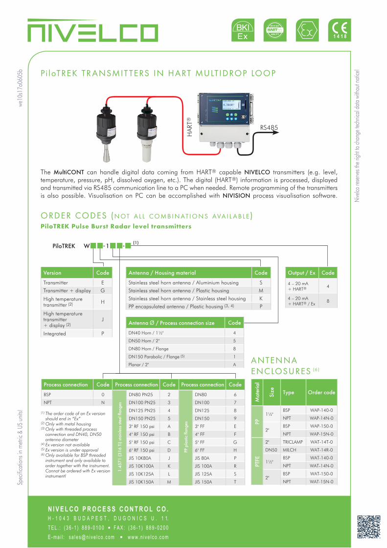
P i loTREK TR ANSMIT TERS IN HART MULTIDROP LOOP
The MultiCONT can handle digital data coming from HART® capable NIVELCO transmitters (e.g. level, temperature, pressure, pH, dissolved oxygen, etc.). The digital (HART®) information is processed, displayed and transmitted via RS485 communication line to a PC when needed. Remote programming of the transmitters is also possible. Visualisation on PC can be accomplished with NIVISION process visualisation software.
ORDER CODES (n ot a l l com b i n at i o n s ava i l a b l e)PiloTREK Pulse Burst Radar level transmitters
Mat
eria
l
Size Type Order code
PP
1½"BSP WAP-140-0
NPT WAP-14N-0
2"BSP WAP-150-0
NPT WAP-15N-0
PTFE
2" TRICLAMP WAT-14T-0
DN50 MILCH WAT-14R-0
1½"BSP WAT-140-0
NPT WAT-14N-0
2"BSP WAT-150-0
NPT WAT-15N-0
ANTENNA ENCLOSURES (6)
Version Code
Transmitter E
Transmitter + display G
High temperature transmitter (2) H
High temperature transmitter + display (2)
J
Integrated P
Antenna / Housing material Code
Stainless steel horn antenna / Aluminium housing S
Stainless steel horn antenna / Plastic housing M
Stainless steel horn antenna / Stainless steel housing K
PP encapsulated antenna / Plastic housing (3, 4) P
Output / Ex Code
4 – 20 mA + HART® 4
4 – 20 mA + HART® / Ex
8
Process connection Code Process connection Code Process connection Code
BSP 0
1.45
71 (3
16 T
i) st
ainl
ess
stee
l fla
nges
DN80 PN25 2
PP p
last
ic fl
ange
s
DN80 6
NPT N DN100 PN25 3 DN100 7
DN125 PN25 4 DN125 8
DN150 PN25 5 DN150 9
3" RF 150 psi A 3" FF E
4" RF 150 psi B 4" FF F
5" RF 150 psi C 5" FF G
6" RF 150 psi D 6" FF H
JIS 10K80A J JIS 80A P
JIS 10K100A K JIS 100A R
JIS 10K125A L JIS 125A S
JIS 10K150A M JIS 150A T
PiloTREK W - 1 - (1)
(1) The order code of an Ex version should end in “Ex”
(2) Only with metal housing(3) Only with threaded process
connection and DN40, DN50 antenna diameter
(4) Ex version not available(5) Ex version is under approval(6) Only available for BSP threaded
instrument and only available to order together with the instrument. Cannot be ordered with Ex version instrument!
Antenna Ø / Process connection size Code
DN40 Horn / 1½" 4
DN50 Horn / 2" 5
DN80 Horn / Flange 8
DN150 Parabolic / Flange (5) 1
Planar / 2" A
Nive
lco re
serve
s the
righ
t to ch
ange
tech
nical
data
witho
ut no
tice!
we10
s17a
0605
bSp
ecific
atio
ns in
metr
ic &
US u
nits!
N I V E L C O P R O C E S S C O N T R O L C O .H - 1 0 4 3 B U D A P E S T , D U G O N I C S U . 1 1.T E L . : ( 3 6 - 1 ) 8 8 9 - 0 1 0 0 ▪ F A X : ( 3 6 - 1 ) 8 8 9 - 0 2 0 0E - m a i l : s a l e s @ n i v e l c o . c o m ▪ w w w . n i v e l c o . c o m
HAR
T®
RS485

TECHNICAL DATA
SPECIAL DATA FOR EX CERTIFIED MODELS
Type IntegratedCompact
Plastic housing Metal housing High temperature version
Measured values Level, Distance; Calculated values: Volume, Mass
Frequency of the measurement signal ~25 GHz (K-band)
Measuring range 0.2 m – 23 m (0.6 feet – 75 feet) (depending on the antenna type – see: special data of the antenna variations)
Linearity error (1) <0.5 m (1.65 ft): ±25 mm (±1 in); 0.5 – 1 m (1.65 – 3.3 ft): ±15 mm (±0.6 in); 1m – 1.5 m (3.3 – 5 ft): ±10 mm (±0.4 in); 1.5 – 8 m (5 – 26.25 ft): ±3 mm (±0.12 in); >8 m (26.25 ft): ±0.04% of the measured distance
Minimal beam angle 11° (depending on the antenna type) 6° (depending on the antenna type; see: special data of the antenna variations)
Minimal er of the medium 1.9 (depending on the meas. range) 1.4 (depending on the meas. range; see: max. measurement range vs. er diagram)
Resolution 1 mm (0.04 inch)
Temperature error (as per EN 61298-3) 0.05% FSK / 10 °C (50 °F) (-20 °C … +60 °C [-4 °F … +140 °F])
Power supply 20 V – 36 V DC
OutputDigital communication 4 – 20 mA + HART®
Display – SAP-300 graphical display unit
Measuring frequency 10 – 60 sec as per the application settings
Antenna diameter 38 mm (1½"), 48 mm (2"), 75 mm (3"), 148 mm (6")
Antenna material Horn, Parabolic: 1.4571 (316 Ti) stainless steel; enclosure: PP, PTFEHorn, Parabolic: 1.4571 (316 Ti); enclosure: PTFE
Process temperature-30 ºC … +100 ºC (-22 ºF … +212 ºF), (up to 120 ºC (248 ºF) for max. 2 minutes)
with PP antenna enclosure: max.: 80 ºC (+176 ºF)-30 ºC … +180 ºC (-22 ºF … +356 ºF)
Maximal process pressure 25 bar (363 psig) at 120 ºC (248 ºF); with plastic antenna enclosure: 3 bar (44 psig) at 25 ºC (77 ºF)
Ambient temperature -20 ºC … +60 ºC (-4 ºF … +140 ºF)
Process connection Threaded, Flanged or Sanitary connections (as per order codes)
Ingress protection IP68 IP67
Electrical connection
LiYCY type. 2x 0.5 mm2 (AWG20) shielded Ø6 mm (0.25 in) cable;
standard cable length: 5 m (16.5 ft) (can be ordered up to 30 m (100 ft))
2x M20 x1.5 cable glands + internal thread for 2x ½" NPT cable protective pipe, cable outer diameter: Ø7 – Ø13 mm (0.3 – 0.5 inch),
wire cross section: max. 1.5 mm2 (AWG 15)
Electrical protection Class III
Housing material Plastic (PP) Plastic (PBT) Paint coated aluminium or stainless steel
Sealing Viton, EPDM
Communication certifications R&TTE, FCC
Mass 1 – 1.6 kg (2.2 – 3.5 lb)
Aluminium: 2 – 2.6 kg (4.4 – 5.7 lb)
Stainless steel: 3.3 – 3.9 kg (7.9 – 8.6 lb)
Aluminium: 2.7 – 3.3 kg (6.6 – 7.9 lb)
Stainless steel: 4 – 4.6 kg (8.8 – 10 lb)
(1) Under reference conditions of reflection and stabilized temperature
TypePlastic housing, integrated
WPM-1 -
Plastic housing,compact
W M-1 -
Metal housing W S-1 - W K-1 -
High temperature version with metal housing
WH -1 - , WJ -1 -
Protection type Intrinsically safe
Ex marking
IEC Ex Ex ia IIB T6 … T5 Ga Ex ia IIB T6 … T5 Ga/GbEx ia IIB T6 … T4 Ga Ex ia IIIC
T85 °C … T110 °C Da/Db Ex ta/tb IIIC T85 °C … T110 °C Da/Db
Ex ia IIB T6 … T3 Ga Ex ia IIIC T85 °C … T180 °C Da/Db Ex ta/tb IIIC
T85 °C … T180 °C Da/Db
ATEXx II 1 G Ex ia IIB
T6 … T5 Gax II 1/2 G Ex ia
IIB T6 … T5 Ga/Gb
x II 1G Ex ia IIB T6 … T4 Ga x II 1/2 D Ex ia IIIC
T85 °C … T110 °C Da/Db x II 1/2 D Ex ta/tb IIIC
T85 °C … T110 °C Da/Db
x II 1G Ex ia IIB T6 … T3 Ga x II 1/2 D Ex ia IIIC
T85 °C … T180 °C Da/Db x II 1/2 D Ex ta/tb IIIC
T85 °C … T180 °C Da/Db
Intrinsically safe dataUi = 30 V,
Ii = 140 mA, Pi = 1 W, Ci = 30 nF, Li = 200 μH
Ui = 30 V, Ii = 140 mA, Pi = 1 W, Ci = 16 nF, Li = 200 μH
Power supply 20 – 30 V DC
Ambient temperature -20 °C … +60 °C (-4 °F … +140 °F)
Electrical connection
In case of WPM type: LiYCY type. 2x 0.5 mm2 (AWG20) shielded Ø6 mm (0.25 in)
cable; standard cable length: 5 m (16.5 ft) (can be ordered
up to 30 m (100 ft))
2x M20 x1.5 metal cable glands, cable outer diameter: Ø7 – Ø13 mm (0.3 – 0.5 inch), wire cross section: max. 1.5 mm2 (AWG 15)
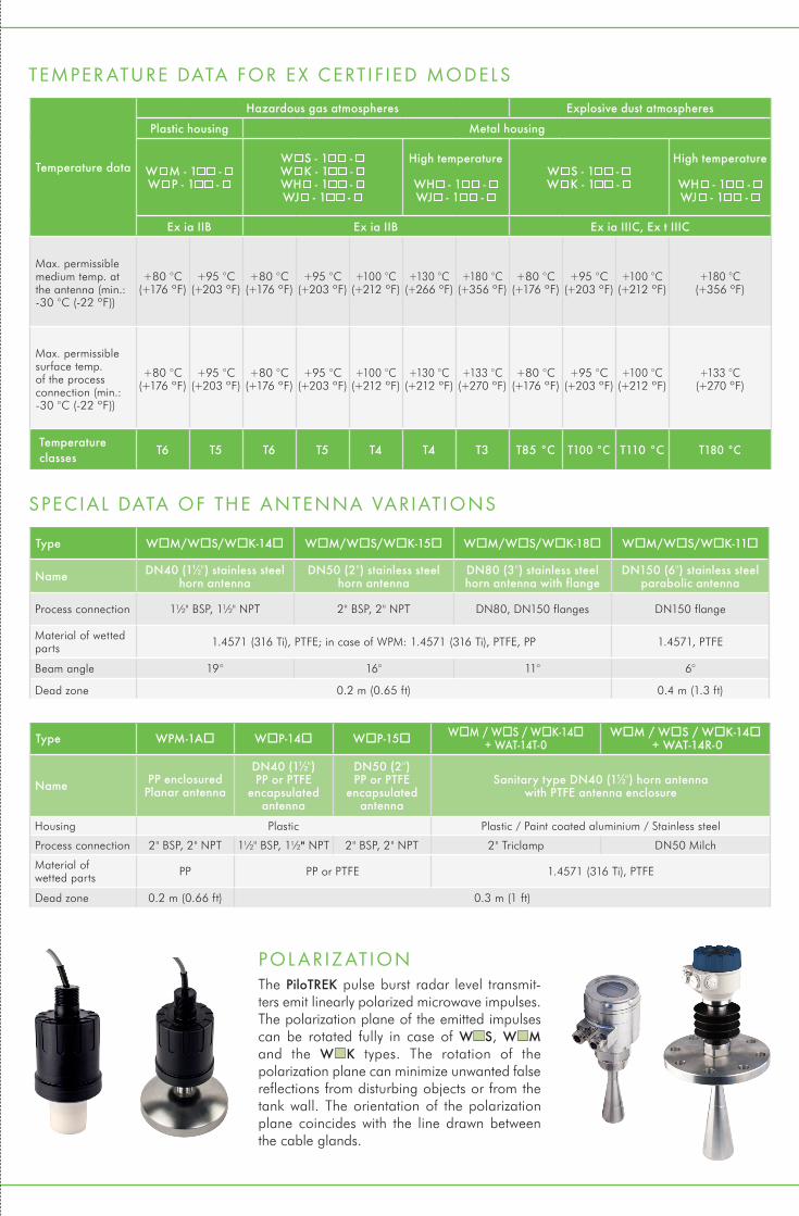
TEMPER ATURE DATA FOR EX CERTIFIED MODELS
SPECIAL DATA OF THE ANTENNA VARIATIONS
Temperature data
Hazardous gas atmospheres Explosive dust atmospheres
Plastic housing Metal housing
W M - 1 - W P - 1 -
W S - 1 - W K - 1 - WH - 1 - WJ - 1 -
High temperature
WH - 1 - WJ - 1 -
W S - 1 - W K - 1 -
High temperature
WH - 1 - WJ - 1 -
Ex ia IIB Ex ia IIB Ex ia IIIC, Ex t IIIC
Max. permissible medium temp. at the antenna (min.: -30 °C (-22 ºF))
+80 °C(+176 ºF)
+95 °C(+203 ºF)
+80 °C(+176 ºF)
+95 °C(+203 ºF)
+100 °C(+212 ºF)
+130 °C(+266 ºF)
+180 °C(+356 ºF)
+80 °C(+176 ºF)
+95 °C(+203 ºF)
+100 °C(+212 ºF)
+180 °C(+356 ºF)
Max. permissible surface temp. of the process connection (min.: -30 °C (-22 ºF))
+80 °C(+176 ºF)
+95 °C(+203 ºF)
+80 °C(+176 ºF)
+95 °C(+203 ºF)
+100 °C(+212 ºF)
+130 °C(+212 ºF)
+133 °C(+270 ºF)
+80 °C(+176 ºF)
+95 °C(+203 ºF)
+100 °C(+212 ºF)
+133 °C(+270 ºF)
Temperature classes
T6 T5 T6 T5 T4 T4 T3 T85 °C T100 °C T110 °C T180 °C
Type WM/WS/WK-14 WM/WS/WK-15 WM/WS/WK-18 WM/WS/WK-11
Name DN40 (1½") stainless steelhorn antenna
DN50 (2") stainless steelhorn antenna
DN80 (3") stainless steelhorn antenna with flange
DN150 (6") stainless steel parabolic antenna
Process connection 1½" BSP, 1½" NPT 2" BSP, 2" NPT DN80, DN150 flanges DN150 flange
Material of wetted parts 1.4571 (316 Ti), PTFE; in case of WPM: 1.4571 (316 Ti), PTFE, PP 1.4571, PTFE
Beam angle 19° 16° 11° 6°
Dead zone 0.2 m (0.65 ft) 0.4 m (1.3 ft)
Type WPM-1A WP-14 WP-15 WM / WS / WK-14 + WAT-14T-0
WM / WS / WK-14 + WAT-14R-0
Name PP enclosured Planar antenna
DN40 (1½") PP or PTFE
encapsulated antenna
DN50 (2") PP or PTFE
encapsulated antenna
Sanitary type DN40 (1½") horn antenna with PTFE antenna enclosure
Housing Plastic Plastic / Paint coated aluminium / Stainless steel
Process connection 2" BSP, 2" NPT 1½" BSP, 1½" NPT 2" BSP, 2" NPT 2" Triclamp DN50 Milch
Material of wetted parts PP PP or PTFE 1.4571 (316 Ti), PTFE
Dead zone 0.2 m (0.66 ft) 0.3 m (1 ft)
POL ARIZ ATIONThe PiloTREK pulse burst radar level transmit-ters emit linearly polarized microwave impulses. The polarization plane of the emitted impulses can be rotated fully in case of W S, W M and the W K types. The rotation of the polarization plane can minimize unwanted false reflections from disturbing objects or from the tank wall. The orientation of the polarization plane coincides with the line drawn between the cable glands.