PUHZ-RP250YHM-A - Mitsubishi Electric Australia
16
OUTDOOR UNIT PUHZ-RP250YHM-A For use with R410A INSTALLATION MANUAL For safe and correct use, please read this installation manual thoroughly before installing the air-conditioner unit. GB
Transcript of PUHZ-RP250YHM-A - Mitsubishi Electric Australia

OUTDOOR UNIT
PUHZ-RP250YHM-A
For use with R410A
INSTALLATION MANUALFor safe and correct use, please read this installation manual thoroughly before installing the air-conditioner unit.
GB

2
5 [Fig. 5.0.1]
[Fig. 6.0.1]6
(2)
(1)
(3)
(4)
[Fig. 5.0.2]
<A> : Top view
<B> : Side view
<C> : When there is little space up to an obstruction
A : Front
B : Unit height
C : Back
D : Air outlet guide (Procured at the site)
A : Front
B : Must be open
C : Wall height (H)
15*15*
450*
300*
<A>
A
100*
450*
50*50*<A>
A
AB
<B>
500
H
h
h
H
240
45°
A
D
C
50<C>
1000
30
450 *
300 *
C
B B
C
A
100 450 *
100 *
B B
C
C
A
450* 100*
C C
B
AA A
B
450 450
15*
C
AAA
450 450
900
300 *
300 *
B B
C
C
A
1000*
900
300 *
B
B
C
A
(mm)
8m
8m
40°
(mm)

3
7[Fig. 7.1.1]
30m
m
A
B
C
8 8.2[Fig. 8.2.1]
A : Outdoor unit
B : Indoor unit
A B
A
7.1
Å Outdoor model
RP250ı Liquid pipe
ø9.52
Ç Gas pipe
ø22.2
A
9.29[Fig. 9.2.1] [Fig. 9.2.2] <A> Valve
liquid side/flared type
A
B
C
H
I
G
F
E
D
( )<B> Valvegas side/flanged type( )
[Fig. 9.2.3]
A B
[Fig. 9.2.4]
A
E
D
C
B
A : Close-packed packing
B : Hollow packing
C : Valve
D : Packing
E : Connecting pipe with flange
A : Example of closure materials (field supply)
B : Fill the gap at the site
A: Service portFor vacuuming in the refrigerant pipes on the site.(Tightening torque 12 N·m)
B: ShaftFully closed at the factory, when connecting the piping, and when vacuuming.Open fully after these operations are completed.<When opening>• Turn the shaft counterclockwise with a hexagonal wrench.• Turn around the shaft until it stops.<When closing>• Turn the shaft clockwise with a hexagonal wrench.• Turn around the shaft until it stops.
C: Flare nutCoat the flare contact surface with refrigerating machine oil (small amount ofester oil, ether oil, or alkyl benzene) and tighten the nut with a double-endedwrench (refer to the following table for tightening torque).
D: CapRemove the cap before operating the shaft. Be sure to return it to the originalposition after completing the operation.
E: PackingCoat both sides of the packing with machine refrigerating oil (small amount ofester oil, ether oil, or alkyl benzene) and tighten the flange.(Tightening torque 25 N·m)
F: Connecting pipe (accessory)Be sure to remove the connecting pipe from the valve and braze it outside the unit.
G: Field pipingBraze to the connecting pipe with unoxidized brazing.
H: ø9.52 mm
I: ø22.2 mm
A: M10 anchor bolt procured at the site.
B Corner is not seated.
C Fixing bracket for hole-in anchor bolt (3 locations to fix with screws).
(mm)
4
[Fig. 9.3.1]
[Fig. 9.3.3]
[Fig. 9.3.2]
9.3
A
A : Nitrogen gas
B : To indoor unit
C : System analyzer
D : Low knob
E : Hi knob
F : Valve
G : Liquid pipe
H : Gas pipe
I : Outdoor unit
J : Service port
A : System analyzer
B : Low knob
C : Hi knob
D : Valve
E : Liquid pipe
F : Gas pipe
G : Service port
H : Three-way joint
I : Valve
J : Valve
K : R410A cylinder
L : Scale
M : Vacuum pump
N : To indoor unit
O : Outdoor unit
A : Syphon pipe
D
C
C
B
B
E
F
G
H
I
JA
LOW HI
LOW HI
B
A
K
J
L
H
M
C
D
EN
NO
F
G
I
9.4
[Fig. 9.4.4]
[Fig. 9.4.3][Fig. 9.4.2]
CAB
D E
[Fig. 9.4.1]B
A
D
C
E
EE
D
AB
A B
<A> Inner wall (concealed)
A BD
C
<B> Outer wall
A : Steel wire B : Piping
C : Asphaltic oily mastic or asphalt
D : Heat insulation material A
E : Outer covering B
A : Liquid pipe B : Gas pipe
C : Electric wire D : Finishing tape
E : Insulator
D
F
G
B
<D> Floor (waterproofing)
E
I
B
<C> Outer wall (exposed)
F
H
DB
G
<E> Roof pipe shaft
I
A
J
1m1m
<F> Penetrating portion on firelimit and boundary wall
A : Sleeve B : Heat insulating material
C : Lagging D : Caulking material
E : Band F : Waterproofing layer
G : Sleeve with edge H : Lagging material
I : Mortar or other incombustible caulking
J : Incombustible heat insulation material
B In case of the R410A cylinder having no syphon pipe.

5
[Fig. 10.4.1]
A : Switch (Breakers forwiring and currentleakage)
B : Breakers for currentleakage
C : Outdoor unit
B AC3N~380–415V
L1, L2, L3, N
PE
C
L1 L2 L3 N
Terminal block for indoor – outdoor transmission line
(TB3)
Power supply terminal block(TB1)
Control box
A B
[Fig. 10.2.1]
10.3
10.2
[Fig. 10.2.2]
A
B C
[Fig. 10.3.1]
10
A : Power source
B : Transmission line
C : Earth screw
A : Cable strap
B : Power source line
C : Transmission line
10.4
M1 M2M1 M2 STB7
TB3
IC
(51)
M1 M2 1 2STB5 TB15
RC
(01)
OC
A BA
A : Shielded wire
6
DF
EI
NL
PG
RR
UT
RC
ZS
VS
LH
GP
OG
B
Contents
1. Safety precautions
1.1. Before installation and electric work
s Before installing the unit, make sure you read all the “Safetyprecautions”.
s The “Safety precautions” provide very important points re-garding safety. Make sure you follow them.
Symbols used in the text
Warning:Describes precautions that should be observed to prevent danger of injuryor death to the user.
Caution:Describes precautions that should be observed to prevent damage to theunit.
Symbols used in the illustrations: Indicates an action that must be avoided.
: Indicates that important instructions must be followed.
: Indicates a part which must be grounded.
: Beware of electric shock. (This symbol is displayed on the main unit label.)<Color: yellow>
Warning:Carefully read the labels affixed to the main unit.
HIGH VOLTAGE WARNING:• Control box houses high-voltage parts.• When opening or closing the front panel of the control box, do not let it
come into contact with any of the internal components.• Before inspecting the inside of the control box, turn off the power, keep
the unit off for at least 10 minutes, and confirm that the voltage betweenFT-P and FT-N on INV Board has dropped to DC20V or less.(It takes about 10 minutes to discharge electricity after the power supplyis turned off.)
Warning:• Ask the dealer or an authorized technician to install the air conditioner.
- Improper installation by the user may result in water leakage, electric shock,or fire.
• Install the unit at a place that can withstand its weight.- Failure to do so may cause the unit to fall down, resulting in injuries and
damage to the unit.• Use the specified cables for wiring. Make the connections securely so
that the outside force of the cable is not applied to the terminals.- Inadequate connection and fastening may generate heat and cause a fire.
• Prepare for strong winds and earthquakes and install the unit at the speci-fied place.- Improper installation may cause the unit to topple and result in injury and
damage to the unit.• Always use filters and other accessories specified by Mitsubishi Electric.
- Ask an authorized technician to install the accessories. Improper installationby the user may result in water leakage, electric shock, or fire.
• Never repair the unit. If the air conditioner must be repaired, consult thedealer.- If the unit is repaired improperly, water leakage, electric shock, or fire may
result.
• Do not touch the heat exchanger fins.- Improper handling may result in injury.
• If refrigerant gas leaks during installation work, ventilate the room.- If the refrigerant gas comes into contact with a flame, poisonous gases will
be released.• Install the air conditioner according to this Installation Manual.
- If the unit is installed improperly, water leakage, electric shock, or fire mayresult.
• Have all electric work done by a licensed electrician according to “ElectricFacility Engineering Standard” and “Interior Wire Regulations” and theinstructions given in this manual and always use a dedicated power supply.- If the power source capacity is inadequate or electric work is performed im-
properly, electric shock and fire may result.• Securely install the outdoor unit terminal cover (panel).
- If the terminal cover (panel) is not installed properly, dust or water may enterthe outdoor unit and fire or electric shock may result.
• When installing and moving the air conditioner to another site, do notcharge it with a refrigerant different from the refrigerant specified on theunit.- If a different refrigerant or air is mixed with the original refrigerant, the refrig-
erant cycle may malfunction and the unit may be damaged.• If the air conditioner is installed in a small room, measures must be taken
to prevent the refrigerant concentration from exceeding the safety limit ifthe refrigerant should leak.- Consult the dealer regarding the appropriate measures to prevent the safety
limit from being exceeded. Should the refrigerant leak and cause the safetylimit to be exceeded, hazards due to lack of oxygen in the room could result.
• When moving and reinstalling the air conditioner, consult the dealer oran authorized technician.- If the air conditioner is installed improperly, water leakage, electric shock, or
fire may result.• After completing installation work, make sure that refrigerant gas is not
leaking.- If the refrigerant gas leaks and is exposed to a fan heater, stove, oven, or
other heat source, it may generate noxious gases.• Do not reconstruct or change the settings of the protection devices.
- If the pressure switch, thermal switch, or other protection device is shortedor operated forcibly, or parts other than those specified by Mitsubishi Electricare used, fire or explosion may result.
• To dispose of this product, consult your dealer.• The installer and system specialist shall secure safety against leakage
according to local regulation or standards.- The size of the wire and capacities of the switch for the main power supply
are applicable if local regulations are not available.• Pay special attention to the place of installation, such as a basement,
etc. where refrigeration gas can accumulate, since refrigeration is heavierthan the air.
• For outdoor units that allow fresh air intake to the indoor unit, theinstallation site must be carefully chosen because outdoor air can directlyblow into the room when the thermostat is turned off.- Direct exposure to outdoor air may have harmful effects on people or food.
1.2. Precautions for devices that use R410Arefrigerant
Caution:• Do not use existing refrigerant piping.
- The old refrigerant and refrigerator oil in the existing piping contains a largeamount of chlorine which may cause the refrigerator oil of the new unit todeteriorate.
- R410A is a high-pressure refrigerant and can cause the existing piping toburst.
1. Safety precautions ...................................................................................... 61.1. Before installation and electric work .......................................... 61.2. Precautions for devices that use R410A refrigerant .................. 61.3. Before installation ...................................................................... 71.4. Before installation (relocation) - electrical work ......................... 71.5. Before starting the test run ........................................................ 7
2. About the product ....................................................................................... 73. Specifications .............................................................................................. 84. Parts included list ........................................................................................ 85. Space required around unit ........................................................................ 86. Lifting method ............................................................................................. 87. Installation of unit ........................................................................................ 8
7.1. Installation ................................................................................. 88. Refrigerant piping installation ..................................................................... 9
8.1. Caution ...................................................................................... 98.2. Refrigerant piping system .......................................................... 9
9. Additional refrigerant charge ..................................................................... 109.1. Calculation of additional refrigerant charge ............................. 109.2. Precautions concerning piping connection and
valve operation ........................................................................ 109.3. Airtight test, evacuation, and refrigerant charging ................... 119.4. Thermal insulation of refrigerant piping ................................... 11
10. Wiring (For details, refer to the installation manual ofeach unit and controller.) .......................................................................... 12
10.1. Caution .................................................................................... 1210.2. Control box and connecting position of wiring ......................... 1210.3. Wiring transmission cables ...................................................... 1210.4. Wiring of main power supply and equipment capacity ............ 12
11. Test run ..................................................................................................... 1311.1. The following phenomena do not represent faults. .................. 13

7
DF
EI
NL
PG
RR
UT
RC
ZS
VS
LH
GP
OG
B
1.4. Before installation (relocation) - electri-cal work
Caution:• Ground the unit.
- Do not connect the ground wire to gas or water pipes, lightning rods, ortelephone ground lines. Improper grounding may result in electric shock.
• Install the power cable so that tension is not applied to the cable.- Tension may cause the cable to break and generate heat and cause a fire.
• Install a leak circuit breaker, as required.- If a leak circuit breaker is not installed, electric shock may result.
• Use power line cables of sufficient current carrying capacity and rating.- Cables that are too small may leak, generate heat, and cause a fire.
• Use only a circuit breaker and fuse of the specified capacity.- A fuse or circuit breaker of a larger capacity, or the use of a substitute simple
steel or copper wire may result in a general unit failure or fire.• Do not wash the air conditioner units.
- Washing them may cause an electric shock.• Be careful that the installation base is not damaged by long use.
- If the damage is left uncorrected, the unit may fall and cause personal injuryor property damage.
• Install the drain piping according to this Installation Manual to ensureproper drainage. Wrap thermal insulation around the pipes to preventcondensation.- Improper drain piping may cause water leakage causing damage to furniture
and other possessions.• Be very careful about transporting the product.
- One person should not carry the product. Its weight is in excess of 20kg.- Some products use PP bands for packaging. Do not use any PP bands as a
means of transportation. It is dangerous.- Do not touch the heat exchanger fins. Doing so may cut your fingers.- When transporting the outdoor unit, support it at the specified positions on
the unit base. Also support the outdoor unit at four points so that it cannotslip sideways.
• Safely dispose of the packing materials.- Packing materials, such as nails and other metal or wooden parts, may cause
stabs or other injuries.- Tear apart and throw away plastic packaging bags so that children will not
play with them. If children play with a plastic bag which has not been tornapart, they face the risk of suffocation.
1.5. Before starting the test run Caution:
• Turn on the power at least 12 hours before starting operation.- Starting operation immediately after turning on the main power switch can
result in irreversible damage to internal parts. Keep the power switch turnedon during the operational season. Make sure of the phase order of powersupply and voltage between each phase.
• Do not touch the switches with wet fingers.- Touching a switch with wet fingers can result in an electric shock.
• Do not touch the refrigerant pipes during and immediately after opera-tion.- During and immediately after operation, the refrigerant pipes may be hot or
cold, depending on the condition of the refrigerant flowing through the refrig-erant piping, compressor, and other refrigerant cycle parts. Your hands maysuffer burns or frostbite if you touch the refrigerant pipes.
• Do not operate the air conditioner with the panels and guards removed.- Rotating, hot, or high-voltage parts can cause injuries.
• Do not turn off the power immediately after stopping operation.- Always wait at least 5 minutes before turning off the power. Otherwise,
drainage water leakage or mechanical failure of sensitive parts may occur.• Do not touch the surface of the compressor during servicing.
- If unit is connected to a supply and not running, the crank case heater locatedat the base of the compressor may still be operating.
• Use refrigerant piping made of phosphorus deoxidized copper and cop-per alloy seamless pipes and tubes. In addition, be sure that the innerand outer surfaces of the pipes are clean and free of hazardous sulphur,oxides, dust/dirt, shaving particles, oils, moisture, or any other contami-nant.- Contaminants on the inside of the refrigerant piping may cause the refriger-
ant residual oil to deteriorate.• Store the piping to be used during installation indoors and keep both
ends of the piping sealed until just before brazing. (Store elbows andother joints in a plastic bag.)- If dust, dirt, or water enters the refrigerant cycle, deterioration of the oil and
compressor failure may result.• Apply a small amount of ester oil, ether oil, or alkyl benzene to flares. (for
indoor unit)- Infiltration of a large amount of mineral oil may cause the refrigerator oil to
deteriorate.• Use liquid refrigerant to fill the system.
- If gas refrigerant is used to fill the system, the composition of the refrigerantin the cylinder will change and performance may drop.
• Do not use a refrigerant other than R410A.- If another refrigerant (R22, etc.) is mixed with R410A, the chlorine in the
refrigerant may cause the refrigerator oil to deteriorate.• Use a vacuum pump with a reverse flow check valve.
- The vacuum pump oil may flow back into the refrigerant cycle and cause therefrigerator oil to deteriorate.
• Do not use the following tools that are used with conventional refriger-ants.(Gauge manifold, charge hose, gas leak detector, reverse flow check valve,refrigerant charge base, refrigerant recovery equipment)- If the conventional refrigerant and refrigerator oil are mixed in the R410A,
the refrigerant may deteriorated.- If water is mixed in the R410A, the refrigerator oil may deteriorate.- Since R410A does not contain any chlorine, gas leak detectors for conven-
tional refrigerants will not react to it.• Do not use a charging cylinder.
- Using a charging cylinder may cause the refrigerant to deteriorate.• Be especially careful when managing the tools.
- If dust, dirt, or water gets into the refrigerant cycle, the refrigerant may dete-riorate.
1.3. Before installation Caution:
• Do not install the unit where combustible gas may leak.- If the gas leaks and accumulates around the unit, an explosion may result.
• Do not use the air conditioner where food, pets, plants, precision instru-ments, or artwork are kept.- The quality of the food, etc. may deteriorate.
• Do not use the air conditioner in special environments.- Oil, steam, sulfuric smoke, etc. can significantly reduce the performance of
the air conditioner or damage its parts.• When installing the unit in a hospital, communication station, or similar
place, provide sufficient protection against noise.- Inverter equipment, private power generator, high-frequency medical equip-
ment, or radio communication equipment may cause the air conditioner tooperate erroneously, or fail to operate. On the other hand, the air conditionermay affect such equipment by creating noise that disturbs medical treatmentor image broadcasting.
• Do not install the unit on a structure that may cause leakage.- When the room humidity exceeds 80% or when the drain pipe is clogged,
condensation may drip from the indoor unit. Perform collective drainage worktogether with the outdoor unit, as required.
2. About the product• This unit uses R410A-type refrigerant.
• Piping for systems using R410A may be different from that for systems usingconventional refrigerant because the design pressure in systems using R410Ais higher. Refer to the Data Book for more information.
• Some of the tools and equipment used for installation with systems that useother types of refrigerant cannot be used with the systems using R410A. Referto the Data Book for more information.
• Do not use the existing piping, as it contains chlorine, which is found in con-ventional refrigerating machine oil and refrigerant. This chlorine will deterioratethe refrigerant machine oil in the new equipment. The existing piping must notbe used as the design pressure in systems using R410A is higher than that inthe systems using other types of refrigerant and the existing pipes may burst.
8
DF
EI
NL
PG
RR
UT
RC
ZS
VS
LH
GP
OG
B
7. Installation of unit
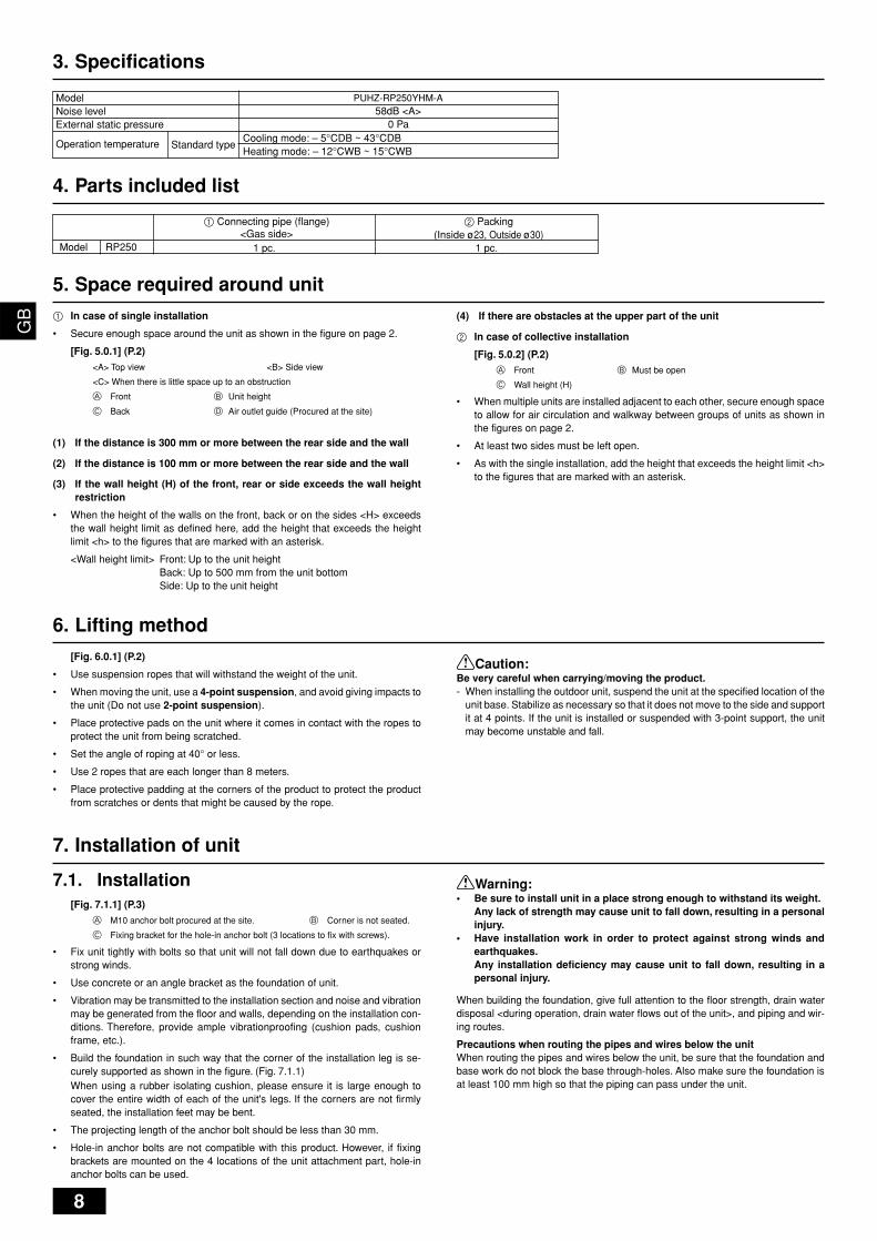
7.1. Installation[Fig. 7.1.1] (P.3)
A M10 anchor bolt procured at the site. B Corner is not seated.
C Fixing bracket for the hole-in anchor bolt (3 locations to fix with screws).
• Fix unit tightly with bolts so that unit will not fall down due to earthquakes orstrong winds.
• Use concrete or an angle bracket as the foundation of unit.
• Vibration may be transmitted to the installation section and noise and vibrationmay be generated from the floor and walls, depending on the installation con-ditions. Therefore, provide ample vibrationproofing (cushion pads, cushionframe, etc.).
• Build the foundation in such way that the corner of the installation leg is se-curely supported as shown in the figure. (Fig. 7.1.1)When using a rubber isolating cushion, please ensure it is large enough tocover the entire width of each of the unit's legs. If the corners are not firmlyseated, the installation feet may be bent.
• The projecting length of the anchor bolt should be less than 30 mm.
• Hole-in anchor bolts are not compatible with this product. However, if fixingbrackets are mounted on the 4 locations of the unit attachment part, hole-inanchor bolts can be used.
RP250
1 Connecting pipe (flange)<Gas side>
1 pc.
2 Packing(Inside ø23, Outside ø30)
1 pc.
4. Parts included list
Model
5. Space required around unit1 In case of single installation
• Secure enough space around the unit as shown in the figure on page 2.
[Fig. 5.0.1] (P.2)
<A> Top view <B> Side view
<C> When there is little space up to an obstruction
A Front B Unit height
C Back D Air outlet guide (Procured at the site)
(1) If the distance is 300 mm or more between the rear side and the wall
(2) If the distance is 100 mm or more between the rear side and the wall
(3) If the wall height (H) of the front, rear or side exceeds the wall heightrestriction
• When the height of the walls on the front, back or on the sides <H> exceedsthe wall height limit as defined here, add the height that exceeds the heightlimit <h> to the figures that are marked with an asterisk.
<Wall height limit> Front: Up to the unit heightBack: Up to 500 mm from the unit bottomSide: Up to the unit height
(4) If there are obstacles at the upper part of the unit
2 In case of collective installation
[Fig. 5.0.2] (P.2)A Front B Must be open
C Wall height (H)
• When multiple units are installed adjacent to each other, secure enough spaceto allow for air circulation and walkway between groups of units as shown inthe figures on page 2.
• At least two sides must be left open.
• As with the single installation, add the height that exceeds the height limit <h>to the figures that are marked with an asterisk.
6. Lifting method[Fig. 6.0.1] (P.2)
• Use suspension ropes that will withstand the weight of the unit.
• When moving the unit, use a 4-point suspension, and avoid giving impacts tothe unit (Do not use 2-point suspension).
• Place protective pads on the unit where it comes in contact with the ropes toprotect the unit from being scratched.
• Set the angle of roping at 40° or less.
• Use 2 ropes that are each longer than 8 meters.
• Place protective padding at the corners of the product to protect the productfrom scratches or dents that might be caused by the rope.
Caution:Be very careful when carrying/moving the product.- When installing the outdoor unit, suspend the unit at the specified location of the
unit base. Stabilize as necessary so that it does not move to the side and supportit at 4 points. If the unit is installed or suspended with 3-point support, the unitmay become unstable and fall.
3. Specifications
ModelNoise levelExternal static pressure
Standard type
PUHZ-RP250YHM-A58dB <A>
0 Pa
Operation temperatureCooling mode: – 5°CDB ~ 43°CDBHeating mode: – 12°CWB ~ 15°CWB
Warning:• Be sure to install unit in a place strong enough to withstand its weight.
Any lack of strength may cause unit to fall down, resulting in a personalinjury.
• Have installation work in order to protect against strong winds andearthquakes.Any installation deficiency may cause unit to fall down, resulting in apersonal injury.
When building the foundation, give full attention to the floor strength, drain waterdisposal <during operation, drain water flows out of the unit>, and piping and wir-ing routes.
Precautions when routing the pipes and wires below the unitWhen routing the pipes and wires below the unit, be sure that the foundation andbase work do not block the base through-holes. Also make sure the foundation isat least 100 mm high so that the piping can pass under the unit.

9
DF
EI
NL
PG
RR
UT
RC
ZS
VS
LH
GP
OG
B
8. Refrigerant piping installation
The pipe is connected via a terminal-branch type connection in which refrigerantpiping from the outdoor unit is branched at the terminal and is connected to eachof the indoor units.The method of pipe connection is as follows: flare connection for the indoor units,gas pipes for outdoor units, brazed connection; liquid pipes, flare connection. Notethat the branched sections are brazed.
Warning:Always use extreme care to prevent the refrigerant gas from leaking whileusing fire or flame. If the refrigerant gas comes in to contact with a flamefrom any source, such as a gas stove, it breaks down and generates a poi-sonous gas which can cause gas poisoning. Never weld in an unventilatedroom. Always conduct an inspection for gas leakage after installation of therefrigerant piping has been completed.
8.1. CautionThis unit uses refrigerant R410A. Follow the local regulations on materials andpipe thickness when selecting pipes. (Refer to the table below.)
1 Use the following materials for refrigeration piping.• Material: Use copper alloy seamless pipes made of phosphorus deoxi-
dized copper. Ensure the inner and outer surfaces of the pipes are cleanand free from hazardous sulfur, oxide, dusts, shaving particles, oils, andmoisture (contamination).
• Size: Refer to item 8.2. for detailed information on refrigerant piping sys-tem.
2 Commercially available piping often contains dust and other materials. Alwaysblow it clean with a dry inert gas.
3 Use care to prevent dust, water or other contaminants from entering the pipingduring installation.
4 Reduce the number of bending portions as much as possible, and make bend-ing radii as big as possible.
5 Always observe the restrictions on the refrigerant piping (such as rated length,height difference, and piping diameter) to prevent equipment failure or a de-cline in heating/cooling performance.
6 Either a lack or an excess of refrigerant causes the unit to make an emergencystop. Charge the system with an appropriate amount of refrigerant. When serv-icing, always check the notes concerning pipe length and amount of additionalrefrigerant at both locations, the refrigerant volume calculation table on theback of the service panel and the additional refrigerant section on the labelsfor the combined number of indoor units (Refer to item 8.2. for detailed infor-mation on refrigerant piping system).
7 Be sure to charge the system using liquid refrigerant.
Size (mm) Radial thickness (mm) Pipe typeø6.35 0.8 Type-Oø9.52 0.8 Type-Oø12.7 0.8 Type-O
ø15.88 1.0 Type-Oø19.05 1.2 Type-Oø19.05 1.0 Type-1/2H or Hø22.2 1.0 Type-1/2H or Hø25.4 1.0 Type-1/2H or H
ø28.58 1.0 Type-1/2H or Hø31.75 1.1 Type-1/2H or Hø34.93 1.2 Type-1/2H or Hø41.28 1.4 Type-1/2H or H
Copper pipe size and radial thickness for R410A.
* For pipe sized ø19.05 for R410A air conditioner, choice of pipe type is up to you.
8 Never use refrigerant to perform an air purge. Always evacuate using avacuum pump.
9 Always insulate the piping properly. Insufficient insulation will result in a de-cline in heating/cooling performance, water drops from condensation and othersuch problems (Refer to item 9.4 for thermal insulation of refrigerant piping).
0 When connecting the refrigerant piping, make sure the valve of the outdoorunit is completely closed (the factory setting) and do not operate it until therefrigerant piping for the outdoor and indoor units has been connected, a re-frigerant leakage test has been performed and the evacuation process hasbeen completed.
A Braze only with non-oxide brazing material for piping. Failure to do somay damage the compressor. Be sure to perform the non-oxidation braz-ing with a nitrogen purge.Do not use any commercially available anti-oxidizing agent since it maycause pipe corrosion and degrading of the refrigerant oil.Please contact Mitsubishi Electric for more details.(Refer to item 9.2. for details of the piping connection and valve operation)
B Never perform outdoor unit piping connection work when it is raining.
Warning:When installing and moving the unit, do not charge the system with anyother refrigerant other than the refrigerant specified on the unit.- Mixing of a different refrigerant, air, etc. may cause the refrigerant cycle to mal-
function and may result in severe damage.
Caution:• Use a vacuum pump with a reverse flow check valve.
- If the vacuum pump does not have a reverse flow check valve, the vacuumpump oil may flow back into the refrigerant cycle and cause deterioration ofthe refrigerator oil.
• Do not use the tools shown below used with conventional refrigerant.(Gauge manifold, charge hose, gas leak detector, check valve, refrigerantcharge base, vacuum gauge, refrigerant recovery equipment)- Mixing of conventional refrigerant and refrigerator oil may cause the refrig-
erator oil to deteriorate.- Mixing of water will cause the refrigerator oil to deteriorate.- R410A refrigerant does not contain any chlorine. Therefore, gas leak detec-
tors for conventional refrigerants will not react to it.• Manage the tools used for R410A more carefully than normal.
- If dust, dirt, or water gets in the refrigerant cycle, the refrigerator oil will dete-riorate.
• Never use existing refrigerant piping.- The large amount of chlorine in conventional refrigerant and refrigerator oil
in the existing piping will cause the new refrigerant to deteriorate.• Store the piping to be used during installation indoors and keep both
ends of the piping sealed until just before brazing.- If dust, dirt, or water gets into the refrigerant cycle, the oil will deteriorate and
the compressor may fail.• Do not use a charging cylinder.
- Using a charging cylinder may cause the refrigerant to deteriorate.• Do not use special detergents for washing piping.
8.2. Refrigerant piping systemConnection example
[Fig. 8.2.1] (P.3)
Å Outdoor model ı Liquid pipe
Ç Gas pipe
A Outdoor unit B Indoor unit

10
DF
EI
NL
PG
RR
UT
RC
ZS
VS
LH
GP
OG
B
At the time of shipping, the outdoor unit is charged with refrigerant.This charge does not include the amount needed for extended piping and addi-tional charging of each refrigerant line will be required on site. In order that futureservicing may be properly provided, always keep a record of the size and length ofeach refrigerant line and the amount of additional charge by writing it in the spaceprovided on the outdoor unit.
9.1. Calculation of additional refrigerantcharge
• Calculate the amount of additional charge based on the length of the pipingextension and the size of the refrigerant line.
• Use the table below as a guide to calculating the amount of additional chargingand charge the system accordingly.
• If the calculation results in a fraction of less than 0.1 kg, round up to the next0.1 kg. For example, if the result of the calculation was 11.38 kg, round theresult up to 11.4 kg.
<Additional Charge>
9.2. Precautions concerning piping connec-tion and valve operation
• Conduct piping connection and valve operation accurately.
• The gas side connecting pipe is assembled in the factory before shipment.
1 For brazing to the connecting pipe with flange, remove the connecting pipewith flange from the valve, and braze it outside of the unit.
2 The refrigerant circuit is closed with a round, close-packed packing uponshipment to prevent gas leak between flanges. As no operation can bedone under this state, be sure to replace the packing with the hollow pack-ing attached at the piping connection.
3 At the mounting of the hollow packing, wipe off dust attached on the flangesheet surface and the packing. Coat refrigerating machine oil (Ester oil,ether oil or alkylbenzene [small amount]) onto both surfaces of the pack-ing.
[Fig. 9.2.1]A Close-packed packing B Hollow packing
C Valve D Packing
E Connecting pipe with flange
• After evacuation and refrigerant charge, ensure that the handle is fully open. Ifoperating with the valve closed, abnormal pressure will be imparted to thehigh- or low-pressure side of the refrigerant circuit, giving damage to the com-pressor, four-way valve, etc.
• Determine the amount of additional refrigerant charge by using the formula,and charge refrigerant additionally through the service port after completingpiping connection work.
• After completing work, tighten the service port and cap securely so as not togenerate any gas leakage.
• Flare machining dimension for systems using R410A is larger than that forsystems using other types of refrigerant in order to increase the air tightness.
• Refer to the table on the below for flare machining dimensions, and follow theregulations set forth by the local authorities.
flare machining dimension (mm)
Additionalrefrigerant charge
(kg)
Liquid pipe sizeTotal length ofø9.52 × 0.06
(m) × 0.06 (kg/m)
= + 3.0 kg
9. Additional refrigerant charge
[Fig. 9.2.2] (P.3)A Service port
For vacuuming in the refrigerant pipes on the site.(Tightening torque 12 N·m)
B ShaftFully closed at the factory, when connecting the piping, and when vacuuming.Open fully after these operations are completed.<When opening>• Turn the shaft counterclockwise with a hexagonal wrench.• Turn around the shaft until it stops.<When closing>• Turn the shaft clockwise with a hexagonal wrench.• Turn around the shaft until it stops.
C Flare nutCoat the flare contact surface with refrigerating machine oil (small amount ofester oil, ether oil, or alkyl benzene) and tighten the nut with a double-endedwrench (refer to the following table for tightening torque).
D CapRemove the cap before operating the shaft. Be sure to return it to the originalposition after completing the operation.
E PackingCoat both sides of the packing with machine refrigerating oil (small amount ofester oil, ether oil, or alkyl benzene) and tighten the flange.(Tightening torque 25 N·m)
F Connecting pipe (accessory)Be sure to remove the connecting pipe from the valve and braze it outside the unit.
G Field pipingBraze to the connecting pipe with unoxidized brazing.
H ø9.52 mm
I ø22.2 mm
Appropriate tightening torque:
Appropriate tightening torque and its angle:
Warning:When connecting a pipe to the service valve, be sure to use only the suppliedopen-end flare nut, with small holes cut into the flats.
* Using a regular flare nut (i.e., non-supplied) will result in any water that natu-rally flows into the nut being unable to escape.Consequently, when the temperature becomes low, this water inside the nutmay freeze and cause damage to the joint. This, in turn, may result in a gasleakage.
[Fig. 9.2.3]
Note:If a torque wrench is not available, use the following method as a standard;When you tighten the flare nut with a wrench, you will reach a point wherethe tightening torque will abruptly increase. Turn the flare nut beyond thispoint by the angle shown in the table above.
Caution:• Always remove the connecting pipe from the valve and braze it outside
the unit.- Brazing the connecting pipe while it is installed will heat the valve and cause
trouble or gas leakage. The piping, etc. inside the unit may also be burned.• Use ester oil, ether oil or alkylbenzene (small amount) as the refrigerat-
ing machine oil to coat flares and flange connections.- The refrigerating machine oil will degrade if it is mixed with a large amount of
mineral oil.• Keep the valve closed until refrigerant charging to the pipes to be added
on site has been completed. Opening the valve before charging the re-frigerant may result in unit damage.
• Do not use a leak detection additive.
[Fig. 9.2.4]A Example of closure materials (field supply)
B Fill the gap at the site
Make sure to seal-off the space around areas where the wires and refrigerantpipes enter the unit to ensure that small animals, rainwater, or snow cannot enterthe unit through such openings and cause damage to the unit.
A
B
flare nut size (mm)
Outer diameter ofcopper pipe (mm)
ø9.52ø12.7ø15.88ø19.05ø25.4
Shaft (N·m)
59151530
Size of hexagonalwrench (mm)
446610
Cap (N·m)
2220252540
Outer diameter ofcopper pipe (mm)
ø9.52ø12.7ø15.88ø19.05
Tightening torque(N·m)
35 - 4250 - 57.575 - 80
100 - 140
Tightening angle(°)
60 to 90
30 to 60
20 to 35
outer diameter
ø6.35ø9.52ø12.7ø15.88ø19.05
dimension BR410A
17.022.026.029.036.0
outer diameter
ø6.35ø9.52ø12.7ø15.88ø19.05
dimension AR410A
9.113.216.619.724.0

11
DF
EI
NL
PG
RR
UT
RC
ZS
VS
LH
GP
OG
B
Caution:Only use refrigerant R410A.- The use of other refrigerants such as R22 or R407C, which contains chlorine,
will deteriorate the refrigerating machine oil or cause the compressor to malfunc-tion.
2 EvacuationEvacuate with the valve of the outdoor unit closed and evacuate both the con-nection piping and the indoor unit from the service port provided on the valveof the outdoor unit using a vacuum pump. (Always evacuate from the serviceport of both liquid pipe and gas pipe.) After the vacuum reaches 650 Pa [abs],continue evacuation for at least one hour or more. Then, stop the vacuumpump and leave it for 1 hour. Ensure the degree of vacuum has not increased.(If the degree of vacuum increase is larger than 130 Pa, water might haveentered. Apply pressure to dry nitrogen gas up to 0.05 MPa and vacuumagain.) Finally, seal in with the liquid refrigerant through the liquid pipe, andadjust the gas piping to obtain an appropriate amount of the refrigerant duringoperation.* Never perform air purging using refrigerant.
[Fig. 9.3.2] (P.4)
A System analyzer B Low knob C Hi knob
D Valve E Liquid pipe F Gas pipe
G Service port H Three-way joint I Valve
J Valve K R410A cylinder L Scale
M Vacuum pump N To indoor unit O Outdoor unit
Note:• Always add an appropriate amount of refrigerant. Also always charge the
system with liquid refrigerant.• Use a gauge manifold, charging hose, and other parts for the refrigerant
indicated on the unit.• Use a graviometer. (One that can measure down to 0.1 kg.)• Use a vacuum pump with a reverse flow check valve.
(Recommended vacuum gauge: ROBINAIR 14830A Thermistor VacuumGauge)Also use a vacuum gauge that reaches 65 Pa [abs] or below after operat-ing for five minutes.
3 Refrigerant ChargingSince the refrigerant used with the unit is nonazerotropic, it must be charged inthe liquid state. Consequently, when charging the unit with refrigerant from acylinder, if the cylinder does not have a syphon pipe, charge the liquid refriger-ant by turning the cylinder upside-down as shown in Fig. 9.3.3. If the cylinderhas a syphon pipe like that shown in the picture on the right, the liquid refriger-ant can be charged with the cylinder standing upright. Therefore, give carefulattention to the cylinder specifications. If the unit should be charged with gasrefrigerant, replace all the refrigerant with new refrigerant. Do not use the re-frigerant remaining in the cylinder.
[Fig. 9.3.3] (P.4)A Syphon pipe B In case of the R410A cylinder having no syphon pipe.
Heatinsulationmaterial A
Outercovering B
9.4. Thermal insulation of refrigerant pipingBe sure to add insulation work to refrigerant piping by covering liquid pipe and gaspipe separately with enough thickness heat-resistant polyethylene, so that no gapis observed in the joint between indoor unit and insulating material, and insulatingmaterials themselves. When insulation work is insufficient, there is a possibility ofcondensation drip, etc. Pay special attention to insulation work in the ceiling ple-num.
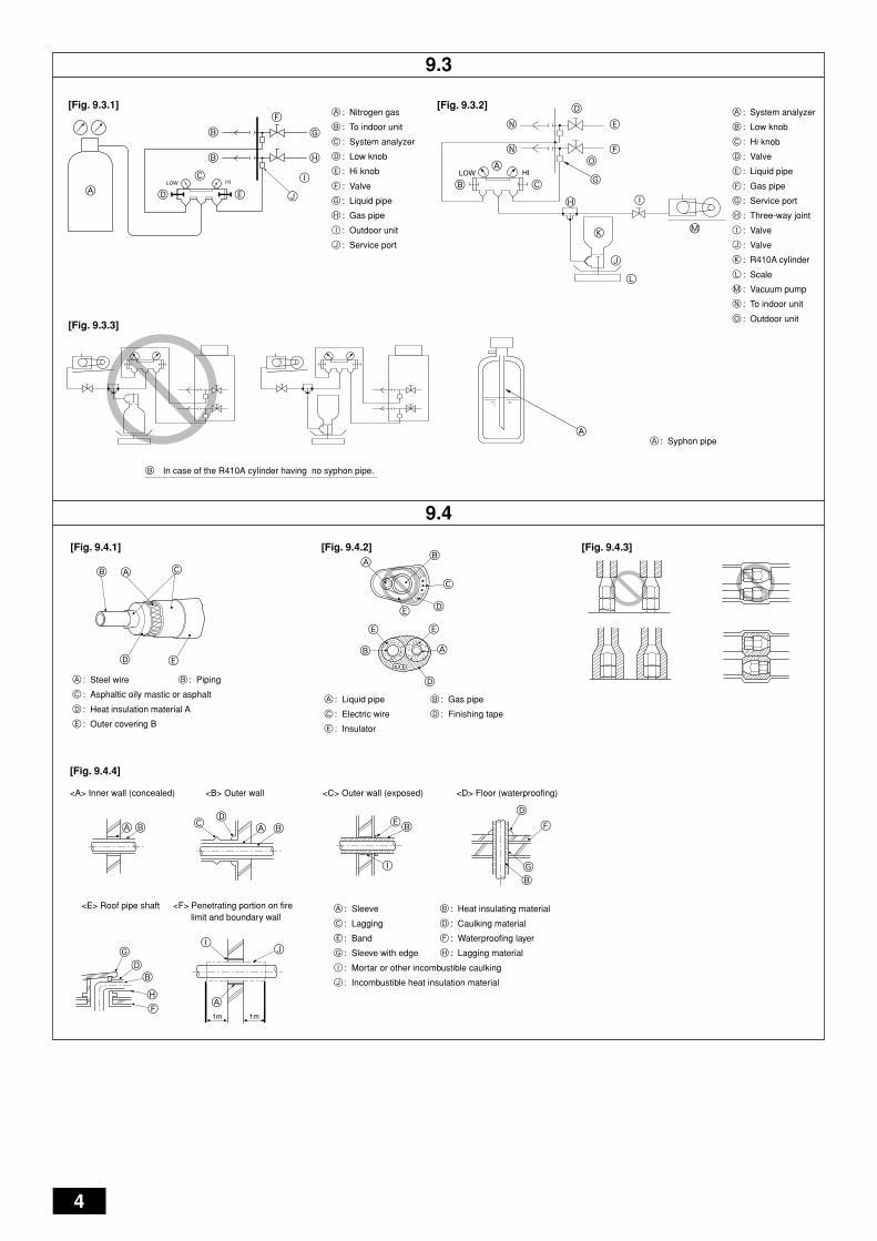
[Fig. 9.4.1] (P.4)A Steel wire B Piping
C Asphaltic oily mastic or asphalt D Heat insulation material A
E Outer covering B
Glass fiber + Steel wire
Adhesive + Heat - resistant polyethylene foam + Adhesive tape
Indoor Vinyl tapeFloor exposed Water-proof hemp cloth + Bronze asphaltOutdoor Water-proof hemp cloth + Zinc plate + Oily paint
Note:• When using polyethylene cover as covering material, asphalt roofing shall
not be required.• No heat insulation must be provided for electric wires.
[Fig. 9.4.2] (P.4)A Liquid pipe B Gas pipe C Electric wire
D Finishing tape E Insulator
[Fig. 9.4.3] (P.4)
Penetrations[Fig. 9.4.4] (P.4)
<A> Inner wall (concealed) <B> Outer wall
<C> Outer wall (exposed) <D> Floor (waterproofing)
<E> Roof pipe shaft
<F> Penetrating portion on fire limit and boundary wall
A Sleeve B Heat insulating material
C Lagging D Caulking material
E Band F Waterproofing layer
G Sleeve with edge H Lagging material
I Mortar or other incombustible caulking
J Incombustible heat insulation material
When filling a gap with mortar, cover the penetration part with steel plate so thatthe insulation material will not be caved in. For this part, use incombustible mate-rials for both insulation and covering. (Vinyl covering should not be used.)
• Insulation materials for the pipes to be added on site must meet the followingspecifications:
* Installation of pipes in a high-temperature high-humidity environment, such asthe top floor of a building, may require the use of insulation materials thickerthan the ones specified in the chart above.
* When certain specifications presented by the client must be met, ensure thatthey also meet the specifications on the chart above.
Caution:Make sure to seal-off and excess space around areas where the wires andrefrigerant pipes enter the unit.• Small animals, rainwater, or snow entering through the openings may
cause damage to the device.
9.3. Airtight test, evacuation, and refrigerantcharging
1 Airtight testPerform with the valve of the outdoor unit closed, and pressurize the connec-tion piping and the indoor unit from the service port provided on the valve ofthe outdoor unit. (Always pressurize from both the liquid pipe and the gas pipeservice ports.)
Restriction
• If a flammable gas or air (oxygen) is used as the pressurizationgas, it may catch fire or explode.
Airtight test procedure
(1) After pressurizing to the design pressure (4.15 MPa) using nitrogen gas, allow it to stand forabout one day. If the pressure does not drop, airtightness is good.However, if the pressure drops, since the leaking point is unknown, the following bubble testmay also be performed.
(2) After the pressurization described above, spray the flare connection parts, brazed parts, andother parts that may leak with a bubbling agent (Kyuboflex, etc.) and visually check for bubbles.
(3) After the airtight test, wipe off the bubbling agent.
[Fig. 9.3.1] (P.4)A Nitrogen gas B To indoor unit C System analyzer
D Low knob E Hi knob F Valve
G Liquid pipe H Gas pipe I Outdoor unit
J Service port
Observe the following restrictions when conducting an air tightness test to preventnegative effects on the refrigerating machine oil. Also, with nonazeotropic refriger-ant (R410A), gas leakage causes the composition to change and affects perform-ance. Therefore, perform the airtightness test cautiously.
ThicknessTemperature Resistance
Pipe sizeø6.35 to 25.4 mm
10 mm min.ø28.58 to 41.28 mm
15 mm min.100°C min.
12
DF
EI
NL
PG
RR
UT
RC
ZS
VS
LH
GP
OG
B
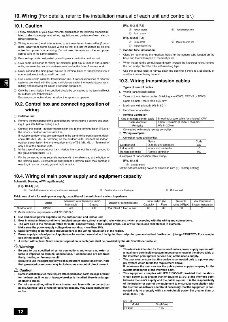
1. Use dedicated power supplies for the outdoor unit and indoor unit.2. Bear in mind ambient conditions (ambient temperature,direct sunlight, rain water,etc.) when proceeding with the wiring and connections.3. The wire size is the minimum value for metal conduit wiring. If the voltage drops, use a wire that is one rank thicker in diameter.
Make sure the power-supply voltage does not drop more than 10%.4. Specific wiring requirements should adhere to the wiring regulations of the region.5. Power supply cords of parts of appliances for outdoor use shall not be lighter than polychloroprene sheathed flexible cord (design 245 IEC57). For example,
use wiring such as YZW.6. A switch with at least 3 mm contact separation in each pole shall be provided by the Air Conditioner installer.
3032 324.0Main cable
Local swtich (A)Minimum wire thickness (mm2)Capacity Fuse
Outdoor unit
Breaker forwiring (NFB) (A)Ground
RP250
Model
30A 100mA 0.1sec. or less
Breaker for current leakage
*1
Max. PermissiveSystem Impedance
10.4. Wiring of main power supply and equipment capacitySchematic Drawing of Wiring (Example)
[Fig. 10.4.1] (P.5)
A Switch (Breakers for wiring and current leakage) B Breakers for current leakage C Outdoor unit
Thickness of wire for main power supply, capacities of the switch and system impedance
10. Wiring (For details, refer to the installation manual of each unit and controller.)
10.1. Caution1 Follow ordinance of your governmental organization for technical standard re-
lated to electrical equipment, wiring regulations and guidance of each electricpower company.
2 Wiring for control (hereinafter referred to as transmission line) shall be (5 cm ormore) apart from power source wiring so that it is not influenced by electricnoise from power source wiring (Do not insert transmission line and powersource wire in the same conduit).
3 Be sure to provide designated grounding work the to the outdoor unit.
4 Give some allowance to wiring for electrical part box of indoor and outdoorunits, because the box is sometimes removed at the time of service work.
5 Never connect the main power source to terminal block of transmission line. Ifconnected, electrical parts will burn out.
6 Use 2-core shield cable for transmission line. If transmission lines of differentsystems are wired with the same multiplecore cable, the resultant poor trans-mitting and receiving will cause erroneous operations.
7 Only the transmission line specified should be connected to the terminal blockfor outdoor unit transmission.Erroneous connection does not allow the system to operate.
10.2. Control box and connecting position ofwiring
1 Outdoor unit
1. Remove the front panel of the control box by removing the 4 screws and push-ing it up a little before pulling it out.
2. Connect the indoor - outdoor transmission line to the terminal block (TB3) forthe indoor - outdoor transmission line.If multiple outdoor units are connected in the same refrigerant system, daisy-chain TB3 (M1, M2, Terminal) on the outdoor units. Connect the indoor -outdoor transmission line for the outdoor units to TB3 (M1, M2, Terminal) ofonly one of the outdoor units.
3. In the case of indoor-outdoor transmission line, connect the shield ground tothe grounding terminal ( ).
4. Fix the connected wires securely in place with the cable strap at the bottom ofthe terminal block. External force applied to the terminal block may damage itresulting in a short circuit, ground fault, or a fire.
[Fig. 10.2.1] (P.5)A Power source B Transmission line
C Earth screw
[Fig. 10.2.2] (P.5)
A Cable strap B Power source line
C Transmission line
2 Conduit tube installation
• Close by hammering the knockout holes for the conduit tube located on thebase and the bottom part of the front panel.
• When installing the conduit tube directly through the knockout holes, removethe burr and protect the tube with masking tape.
• Use the conduit tube to narrow down the opening if there is a possibility ofsmall animals entering the unit.
10.3. Wiring transmission cables1 Types of control cables
1. Wiring transmission cables
• Types of transmission cables: Shielding wire CVVS, CPEVS or MVVS
• Cable diameter: More than 1.25 mm2
• Maximum wiring length: Within 80 m
2. Remote control cables
• Remote Controller
2 Wiring examples
• Controller name and symbol.
<Examples of transmission cable wiring>
[Fig. 10.3.1]
A Shielded wireSet the address setting switch of all unit as zero (0). (factory setting)
Name CodeOutdoor unitIndoor unitRemote controller
Outdoor unit controllerIndoor unit controllerRemote controller
OCICRC
Kind of remote control cableCable diameter
Remarks
Sheathed 2-core cable (unshielded) CVV0.3 to 1.25 mm2 (0.75 to 1.25 mm2)*Within 200 m
* Connected with simple remote controller.
Warning:• Be sure to use specified wires for connections and ensure no external
force is imparted to terminal connections. If connections are not fixedfirmly, heating or fire may result.
• Be sure to use the appropriate type of overcurrent protection switch. Notethat generated overcurrent may include some amount of direct current.
Caution:• Some installation sites may require attachment of an earth leakage breaker
for the inverter. If no earth leakage breaker is installed, there is a dangerof electric shock.
• Do not use anything other than a breaker and fuse with the correct ca-pacity. Using a fuse or wire of too large capacity may cause malfunctionor fire.
Note:• This device is intended for the connection to a power supply system with
a maximum permissible system impedance shown in the above table atthe interface point (power service box) of the user’s supply.
• The user must ensure that this device is connected only to a power sup-ply system which fulfils the requirement above.If necessary, the user can ask the public power supply company for thesystem impedance at the interface point.
• This equipment complies with IEC 61000-3-12 provided that the short-circuit power SSC is greater than or equal to SSC (*2) at the interface pointbetween the user’s supply and the public system. It is the responsibilityof the installer or user of the equipment to ensure, by consultation withthe distribution network operator if necessary, that the equipment is con-nected only to a supply with a short-circuit power SSC greater than orequal to SSC (*2).
SSC (*2)
RP250 1.27Model SSC (MVA)
*1: Meets technical requirements of IEC61000-3-3
4.0

13
DF
EI
NL
PG
RR
UT
RC
ZS
VS
LH
GP
OG
B
11. Test run
11.1. The following phenomena do not represent faults.
Display of remote controllerNormal display
Defrost displayNo lighting
Heat ready
“H0” or “PLEASE WAIT” flashes
Normal display
Normal display
Normal display
CauseUltra-low speed operation is commenced at thermostat OFF.Light air automatically changes over to set value by time or piping temperature atthermostat ON.The fan is to stop during defrosting.The fan is set to run for 1 minute after stopping to exhaust residual heat (only inheating).Ultra low-speed operation for 5 minutes after SW ON or until piping temperaturebecomes 35°C, low speed operation for 2 minutes thereafter, and then set notchis commenced (Hot adjust control).The system is being started up.Operate remote controller again after “H0” or “PLEASE WAIT” disappear.
This is a switching sound of the refrigerant circuit and does not imply a problem.
Unstable flow of the refrigerant emits a sound. This is temporary and does notimply a problem.The LEV is slightly open to prevent refrigerant, of the indoor unit that is notperforming the heating operation, from being liquefied. This does not imply aproblem.
PhenomenonFan setting changes during heating.
Fan stops during heating operation.Fan does not stop while operation has beenstopped.No setting of fan while start SW has beenturned on.
Indoor unit remote controller shows “H0” or“PLEASE WAIT” indicator for about five min-utes when turning ON universal power sup-ply.Indoor unit emits noise when switching fromheating to cooling and vice versa.Immediately after startup, the indoor unitemits the sound of the refrigerant flow.Warm air comes from an indoor unit that isnot performing a heating operation.

GB
EF
IN
LE
PG
RR
UT
R

GB
EF
NL
EP
GR
RU
TR

WT05737X01 Printed in Japan
HEAD OFFICE: TOKYO BLDG., 2-7-3, MARUNOUCHI, CHIYODA-KU, TOKYO 100-8310, JAPAN
Please be sure to put the contact address/telephone number onthis manual before handing it to the customer.
This product is designed and intended for use in the residential,commercial and light-industrial environment.
The product at hand isbased on the followingEU regulations:
• Low Voltage Directive 2006/95/EC• Electromagnetic Compatibility Directive
2004/108/EC• Pressure Equipment Directive 97/23/EC


![SPLIT-TYPE, HEAT PUMP AIR CONDITIONERS · PDF filesplit-type, heat pump air conditioners outdoor unit [model names] puhz-sp100vha puhz-sp125vha puhz-sp140vha ... 14 g s70 e10 699label](https://static.fdocuments.net/doc/165x107/5a9e41fc7f8b9aee4a8bfd4d/split-type-heat-pump-air-conditioners-heat-pump-air-conditioners-outdoor-unit-model.jpg)


![Outdoor unit [Model Name] [Service Ref.] PUHZ-W112VHA PUHZ ...](https://static.fdocuments.net/doc/165x107/625f81d8e8d5824f0710d723/outdoor-unit-model-name-service-ref-puhz-w112vha-puhz-.jpg)


![No.OCH544 SERVICE MANUAL - Mitsubishi Electric...SERVICE MANUAL No.OCH544 SPLIT-TYPE, HEAT PUMP AIR CONDITIONERS R410A August 2013 Outdoor unit [Model name] PUHZ-FRP71VHA [Service](https://static.fdocuments.net/doc/165x107/5e5c9ecb79415e016c776870/nooch544-service-manual-mitsubishi-electric-service-manual-nooch544-split-type.jpg)