Publish 3D for CATIA V5 - Theorem · PDF filePublish 3D User Guide . 2 | Page ©Theorem...
41
Publish 3D for CATIA V5 USER GUIDE Document Revision: 2.0 Issued: 04/01/2018 © THEOREM SOLUTIONS 2018
Transcript of Publish 3D for CATIA V5 - Theorem · PDF filePublish 3D User Guide . 2 | Page ©Theorem...
Publish 3D for CATIA V5
USER GUIDE
Document Revision: 2.0
Issued: 04/01/2018
© THEOREM SOLUTIONS 2018
Publish 3D User Guide
1 | P a g e ©Theorem Solutions 2018
Contents Overview of Publish 3D ............................................................................................................. 2
About Theorem ......................................................................................................................2
Theorem’s Product Suite ........................................................................................................2
What is 3D PDF? .....................................................................................................................3
Who does 3D PDF benefit? .....................................................................................................4
What does Publish 3D provide? .............................................................................................5
Getting Started .......................................................................................................................... 6
Documentation .......................................................................................................................6
Installation Media ...................................................................................................................6
Installation ..............................................................................................................................6
License Configuration .............................................................................................................6
Running the Product ...............................................................................................................7
Using the Product ...................................................................................................................... 8
Publish 3D On-Demand ..........................................................................................................8
Default Publishing ...............................................................................................................8
Default Publishing – via the Unified Interface ................................................................8
Default Publishing – via the Command Line ................................................................ 10
Publishing to Specific List of Templates .......................................................................... 12
Publishing to Targeted Templates – via the Unified Interface .................................... 12
Publishing to Targeted Templates – via the Command Line ....................................... 14
Publishing without a Template ........................................................................................ 16
Publishing without a Template – via the Unified Interface ......................................... 16
Publishing without a Template – via the Command Line ............................................ 17
Publish 3D Customization ........................................................................................................ 19
Common Options for CATIA V5 Publishing .......................................................................... 19
Command Line Advanced Arguments ..................................................................................... 29
CATIA V5 Advanced Arguments........................................................................................... 29
3D PDF Advanced Arguments .............................................................................................. 30
CATIA V5 to 3D PDF Advanced Arguments .......................................................................... 36
Publish 3D Interactive.............................................................................................................. 37
Configuration Manager ....................................................................................................... 39
Security Changes to Adobe Reader PDF Documents .............................................................. 40
Publish 3D User Guide
2 | P a g e ©Theorem Solutions 2018
Overview of Publish 3D
About Theorem
Theorem Solutions is a world leader in the field of Engineering Data Services and Solutions. This leadership position stems from the quality of our technology and the people in the company. Quality comes not only from the skills and commitment of our staff, but also from the vigorous industrial use of our technology & services by world leading customers.
We are proud that the vast majority of the world's leading Automotive, Aerospace, Defense, Power Generation and Transportation companies and their Supply chains use our products and services daily. Working closely with our customers, to both fully understand their requirements and feed their input into our development processes has significantly contributed to our technology and industry knowledge.
Theorem Solutions is an independent UK headquartered company incorporated in 1990, with sales and support offices in the UK and USA. Theorem has strong relationships with the major CAD and PLM vendors, including; Autodesk, Dassault Systemes, ICEM Technologies (a Dassault company), PTC, SolidWorks, Spatial Technology and Siemens PLM Software. These relationships enable us to deliver best in class services and solutions to engineering companies worldwide.
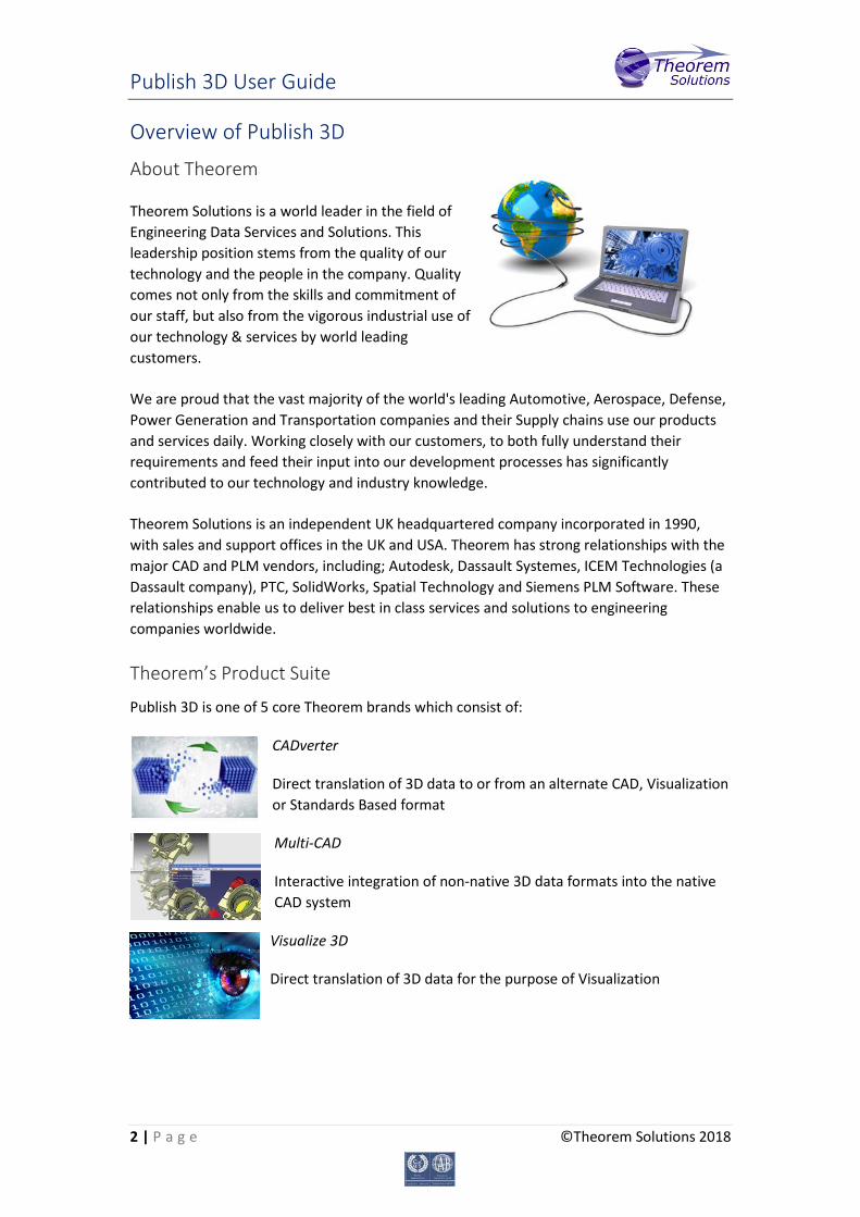
Theorem’s Product Suite
Publish 3D is one of 5 core Theorem brands which consist of:
CADverter
Direct translation of 3D data to or from an alternate CAD, Visualization or Standards Based format
Multi-CAD
Interactive integration of non-native 3D data formats into the native CAD system
Visualize 3D
Direct translation of 3D data for the purpose of Visualization
Publish 3D User Guide
3 | P a g e ©Theorem Solutions 2018
Publish 3D
The creation of documents enriched with 3D content
Process Automation
Applications to automate any Data Exchange and collaboration processes
What is 3D PDF? • It’s PDF so:
– It’s already used for documents which commonly relate to products e.g.; Request for Quotation, Engineering Change Requests, Bill of Material reports, Inspection Documents, Works instructions, Service manuals, Sales literature, etc.
• The 3D definition for PDF was developed by a consortium including Boeing, HP, Adobe, Intel
• The addition of 3D content to PDF allows your company:
– To produce documents to fully describe the product
– To achieve effective communication regarding product information.
– To automate specific business processes
– To improve understanding and eliminate ambiguity in relation to product data.
– To create and extend customised, dynamic documents
– To create rich documents with 3D content which can be consumed anywhere.
– To create interactive and engaging documents such as brochures.
+ =
Publish 3D User Guide
4 | P a g e ©Theorem Solutions 2018
Who does 3D PDF benefit? • Existing technical documentation consumers of
– Maintenance manuals
– Request for Quotation/ Request for Tender
– Sales Brochures
– Etc.
• OEMs and the supply chain
• Sales/Marketing through ‘up-to-date’ and ‘quick to create’ brochures and sales collaterals
• Achieved by enabling
– Enrichment of existing documents and processes saving time and costs
– Re-use of CAD data without sharing IP
– Standard Adobe security
• Password Protection
• Encryption
• Restricted access for specific users with other applications such as LiveCycle, FileOpen etc.
In its simplest form a 3D PDF is a standard Adobe PDF document that contains interactive 3D content. A PDF is a document format that can contain:
• 2D Graphics • 3D Graphics (3D CAD model) • Attached files to form a Technical Data Package • The ability to interrogate and interact with the document. • The ability to universally review CAD with a free viewer. • Compressed data for optimum file size for sharing • Support for Model Based Definition (MBD) • The addition of 3D content to PDF allows your company:
o To produce documents to fully describe the product o To achieve effective communication regarding product information. o To automate specific business processes o To improve understanding and eliminate ambiguity in relation to
product data. o To create and extend customised, dynamic documents o To create rich documents with 3D content which can be consumed
anywhere. o To create interactive and engaging documents such as brochures
Publish 3D User Guide
5 | P a g e ©Theorem Solutions 2018
o It’s already used for documents which commonly relate to products e.g.; Request for Quotation, Engineering Change Requests, Bill of Material reports, Inspection Documents, Works instructions, Service manuals, Sales literature, etc.
It’s already used for documents which commonly relate to products e.g.; Request for Quotation, Engineering Change Requests, Bill of Material reports, Inspection Documents, Works instructions, Service manuals, Sales literature, etc. Review our website here for a short video explaining 3D PDF or review our Frequently asked questions for more information What does Publish 3D provide? A number of Adobe 3D PDF products and solutions are now available as part of the Theorem Solutions Publish 3D suite of applications:
– Publish 3D - Interactive • 3D PDF Publishing from within CAD Applications:
– 3D EXPERIENCE / CATIA V5 / Creo / NX
– Publish 3D - On Demand • Batch Publishing for:
– CATIA V5 / Creo / NX / JT
– Publish 3D - Automated • High volume batch 3D PDF Publishing Complex Workflow Support
The remainder of this document will focus on Publish 3D Document On Demand and Interactive Support for NX to 3D PDF. For further information on other Theorem Publish 3D Products please contact [email protected]
Publish 3D User Guide
6 | P a g e ©Theorem Solutions 2018
Getting Started
Documentation The latest copy of this documentation can be found on our web site at:
http://www.theorem.com/Documentation
Each product has a specific link that provides user documentation in the form of PDF and Tutorials.
Installation Media The latest copy of Theorem software can be found via our web site at:
http://www.theorem.com/Product-Release-Notes Each product has a specific link to the Product Release Document, which contains a link to the download location of the installation CD. Alternatively, you can request a copy of the software to be shipped on a physical CD.
Installation The installation is run from the CD or ZIP file download provided.
Currently, there are 2 distinct installation stages that are required.
To install the translator, select the Setup.exe file and follow the installation process. For a full guide to the process, please see our ‘Translator Installation Process’ demonstration video located here.
In addition, the Theorem Unified Interface will also need to be installed. The installation process is the same as for the Translator. For a full guide to the process, please see our ‘Translator Installation Process’ demonstration video located here.
License Configuration In order for the translation to run successfully, the Theorem license file provided to you needs to be configured using FlexLM. For a full guide to this process, please see our ‘FlexLM License Set Up and Configuration’ demonstration video located here.
Publish 3D User Guide
7 | P a g e ©Theorem Solutions 2018
Running the Product Once configured and licensed, the product is ready to be run.
There are 3 distinct ways of running the translator:
• Via the Theorem Unified Interface
o The Unified Interface offers a Desktop Environment that allows CAD and Visualization data to be viewed pre and post translation
o For a full guide to this process, please see our ‘How to Publish CATIA V5 data to 3D PDF via the User Interface’ demonstration video located here.
• Via the Command Line
o The Command Line Interface provides a direct method of invoking the translator. It can be used on an On Demand basis or called via a third party application as part of a wider process requirement.
o For a full guide to this process, please see our ‘How to Publish CATIA V5 to 3D PDF via the Command Line’ demonstration video located here.
• Interactively from within CATIA V5
o The Interactive Interface provides a direct method of Publishing CATIA V5 data from within CATIA V5 itself.
o For a full guide to this process, please see our ‘How to Publish CATIA V5 to 3D PDF via Interactive mode’ demonstration video located here.
Publish 3D User Guide
8 | P a g e ©Theorem Solutions 2018
Using the Product
Publish 3D On-Demand By default the Publish 3D for CATIA V5 translator will translate source data using a default template.
This template can be used as a basis for a customer’s specific template design and illustrates fundamental capabilities of the translator with regard to publishing 3D data into a pre-defined document format.
More complex template examples are provided in the following the location:
<installation_directory>\data\publish_3dpdf\templates\example_templates
The following examples are available:
• default_template – Illustrates how to output an Assembly Bill of Materials
• publishAttachments – Illustrates adding attachments to a template
• publishBlank – Illustrates publishing to a blank template
<installation_directory>\data\publish_3dpdf\templates\dynamic_templates
The following examples are available:
• publishBOM – Illustrates how to output an Assembly Bill of Materials
• publishMotion – Illustrates using CAD data with motion in PDF
• publishViewer – Illustrates JavaScript additions to a template replicating a CAD viewer
These templates are supplied as examples only and can be used by customers as a guide to creating their own template documents.
Theorem offer a wide range of services to assist customers with their document creation needs. If you would like more information regarding our template design services please contact [email protected] quoting “3D PDF Template Design”.
Default Publishing
Default Publishing – via the Unified Interface The Unified Interface can be started via the Start Menu – if a shortcut was added during installation.
Alternatively, the Unified Interface can be run via a Windows Explorer selection in:
<UI_installation_directory>\bin\Unified_Interface.cmd
Publish 3D User Guide
9 | P a g e ©Theorem Solutions 2018
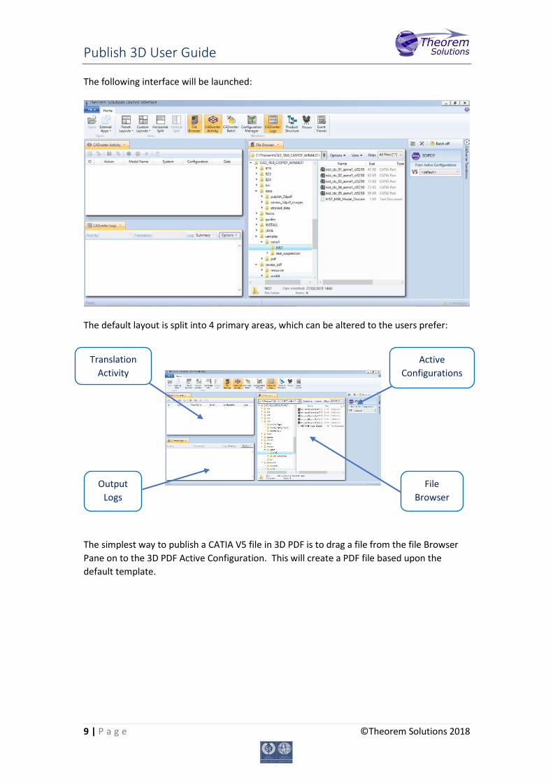
The following interface will be launched:
The default layout is split into 4 primary areas, which can be altered to the users prefer:
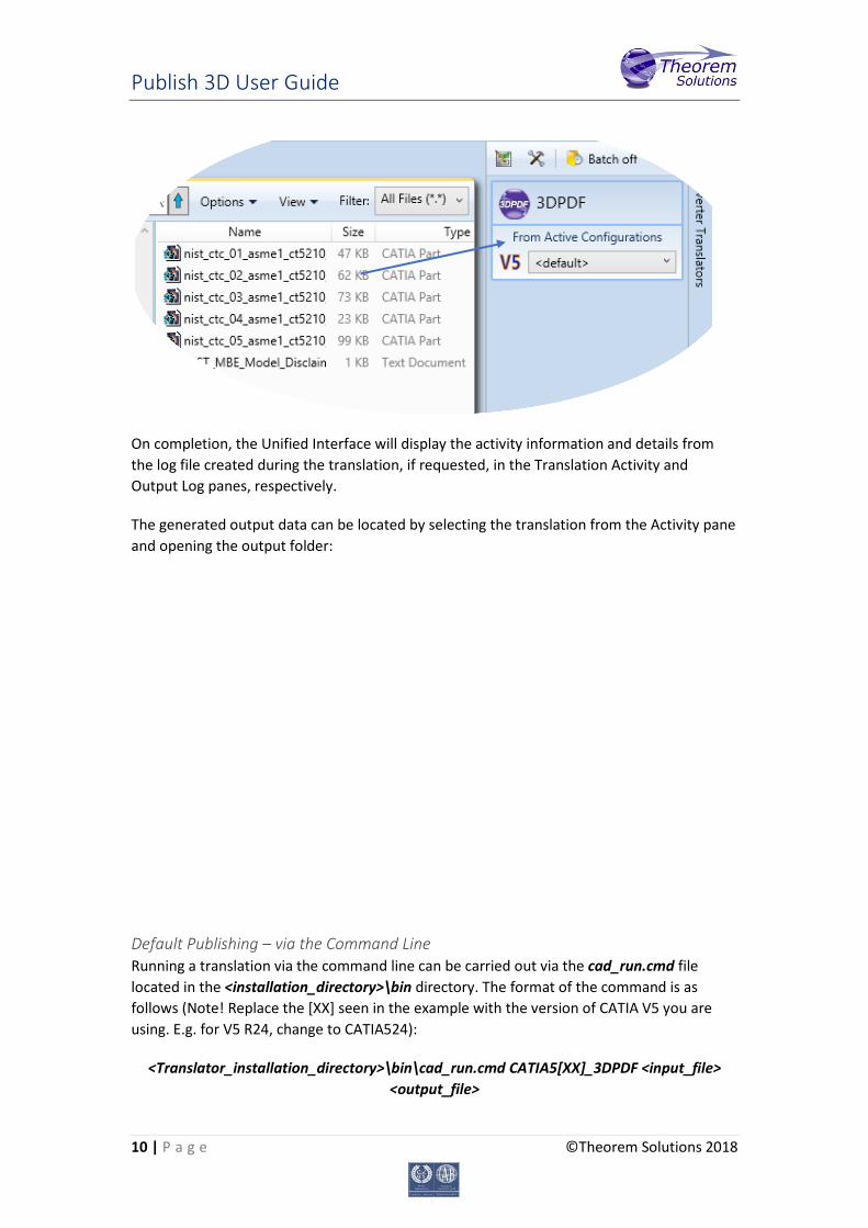
The simplest way to publish a CATIA V5 file in 3D PDF is to drag a file from the file Browser Pane on to the 3D PDF Active Configuration. This will create a PDF file based upon the default template.
File Browser
Active Configurations
Output Logs
Translation Activity
Publish 3D User Guide
10 | P a g e ©Theorem Solutions 2018
On completion, the Unified Interface will display the activity information and details from the log file created during the translation, if requested, in the Translation Activity and Output Log panes, respectively.
The generated output data can be located by selecting the translation from the Activity pane and opening the output folder:
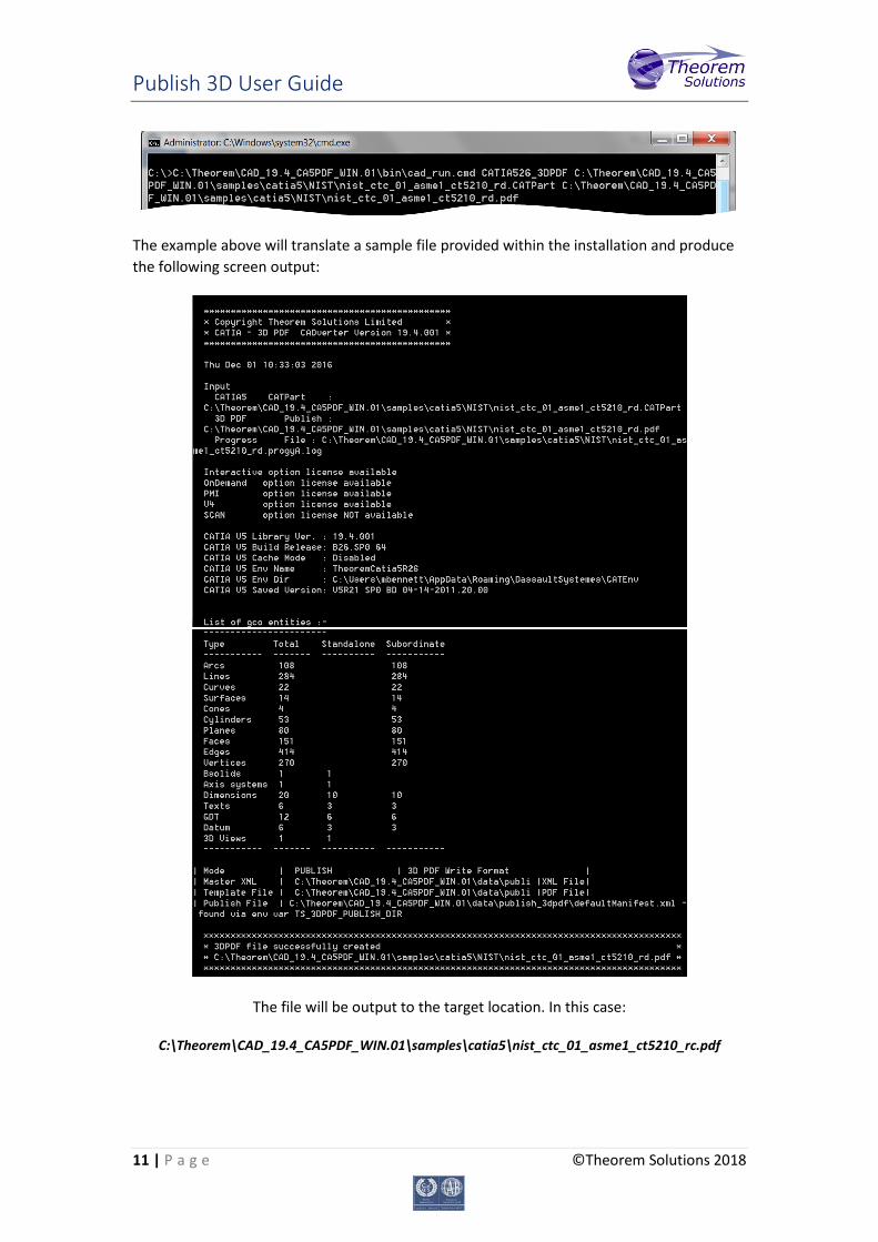
Default Publishing – via the Command Line Running a translation via the command line can be carried out via the cad_run.cmd file located in the <installation_directory>\bin directory. The format of the command is as follows (Note! Replace the [XX] seen in the example with the version of CATIA V5 you are using. E.g. for V5 R24, change to CATIA524):
<Translator_installation_directory>\bin\cad_run.cmd CATIA5[XX]_3DPDF <input_file> <output_file>
Publish 3D User Guide
11 | P a g e ©Theorem Solutions 2018
The example above will translate a sample file provided within the installation and produce the following screen output:
The file will be output to the target location. In this case:
C:\Theorem\CAD_19.4_CA5PDF_WIN.01\samples\catia5\nist_ctc_01_asme1_ct5210_rc.pdf
Publish 3D User Guide
12 | P a g e ©Theorem Solutions 2018
Publishing to Specific List of Templates
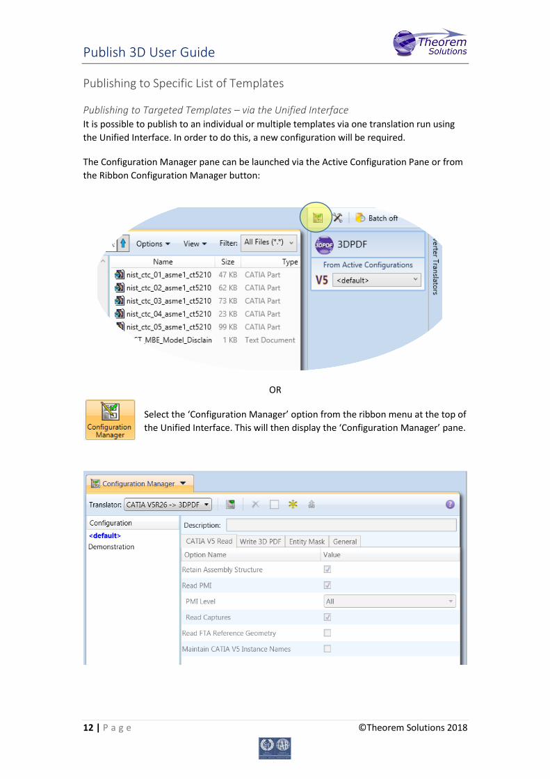
Publishing to Targeted Templates – via the Unified Interface It is possible to publish to an individual or multiple templates via one translation run using the Unified Interface. In order to do this, a new configuration will be required.
The Configuration Manager pane can be launched via the Active Configuration Pane or from the Ribbon Configuration Manager button:
OR
Select the ‘Configuration Manager’ option from the ribbon menu at the top of the Unified Interface. This will then display the ‘Configuration Manager’ pane.
Publish 3D User Guide
13 | P a g e ©Theorem Solutions 2018
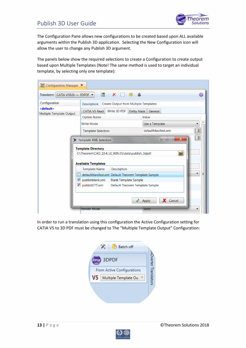
The Configuration Pane allows new configurations to be created based upon ALL available arguments within the Publish 3D application. Selecting the New Configuration icon will allow the user to change any Publish 3D argument.
The panels below show the required selections to create a Configuration to create output based upon Multiple Templates (Note! The same method is used to target an individual template, by selecting only one template):
In order to run a translation using this configuration the Active Configuration setting for CATIA V5 to 3D PDF must be changed to The “Multiple Template Output” Configuration:
Publish 3D User Guide
14 | P a g e ©Theorem Solutions 2018
Once this has been done the translation can be invoked in the same manner as for the Default publishing mechanism.
Publishing to Targeted Templates – via the Command Line Publishing to an individual template or multiple templates can also be achieved via the command line interface.
First a list of target Manifest files that describe how to use a template must be created. (Note! For further information regarding our template design services please contact [email protected] quoting “3D PDF Template Design”.)
The list is provided via a text file in the following format:
C:\Theorem\CAD_19.4_CA5PDF_WIN.01\data\publish_3dpdf\examples\publishBOM.xml C:\Theorem\CAD_19.4_CA5PDF_WIN.01\data\publish_3dpdf\examples\publishDEP.xml C:\Theorem\CAD_19.4_CA5PDF_WIN.01\data\publish_3dpdf\examples\publishDTR.xml
Note! Each line points to an XML manifest file, examples of which are provided in the Publish 3D installation.
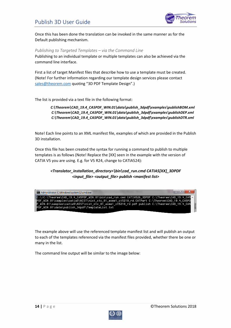
Once this file has been created the syntax for running a command to publish to multiple templates is as follows (Note! Replace the [XX] seen in the example with the version of CATIA V5 you are using. E.g. for V5 R24, change to CATIA524):
<Translator_installation_directory>\bin\cad_run.cmd CATIA5[XX]_3DPDF <input_file> <output_file> publish <manifest list>
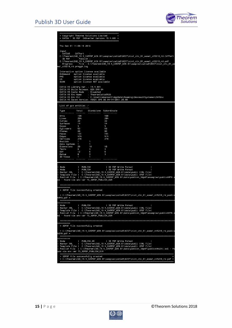
The example above will use the referenced template manifest list and will publish an output to each of the templates referenced via the manifest files provided, whether there be one or many in the list.
The command line output will be similar to the image below:
Publish 3D User Guide
15 | P a g e ©Theorem Solutions 2018

Publish 3D User Guide
16 | P a g e ©Theorem Solutions 2018
Publishing without a Template
Publishing without a Template – via the Unified Interface Running without a template will create a 3D PDF output file with no containing document. In order to do this via the Unified Interface, navigate to the configuration manager as described, and from the ‘Write Mode’ option in the ‘Write 3D PDF’ tab, select ‘No Template’. This configuration is now available for translation.
Now, in the ‘Active Configurations’ pane select your configuration from the menu and then ‘drag and drop’ your data to publish it to a PDF document.
On completion, the Unified Interface will display the activity information and details from the log file created during the translation, if requested, in the Translation Activity and Output Log panes, respectively.
The generated output data can be located by selecting the translation from the Activity pane and opening the output folder:
Publish 3D User Guide
17 | P a g e ©Theorem Solutions 2018
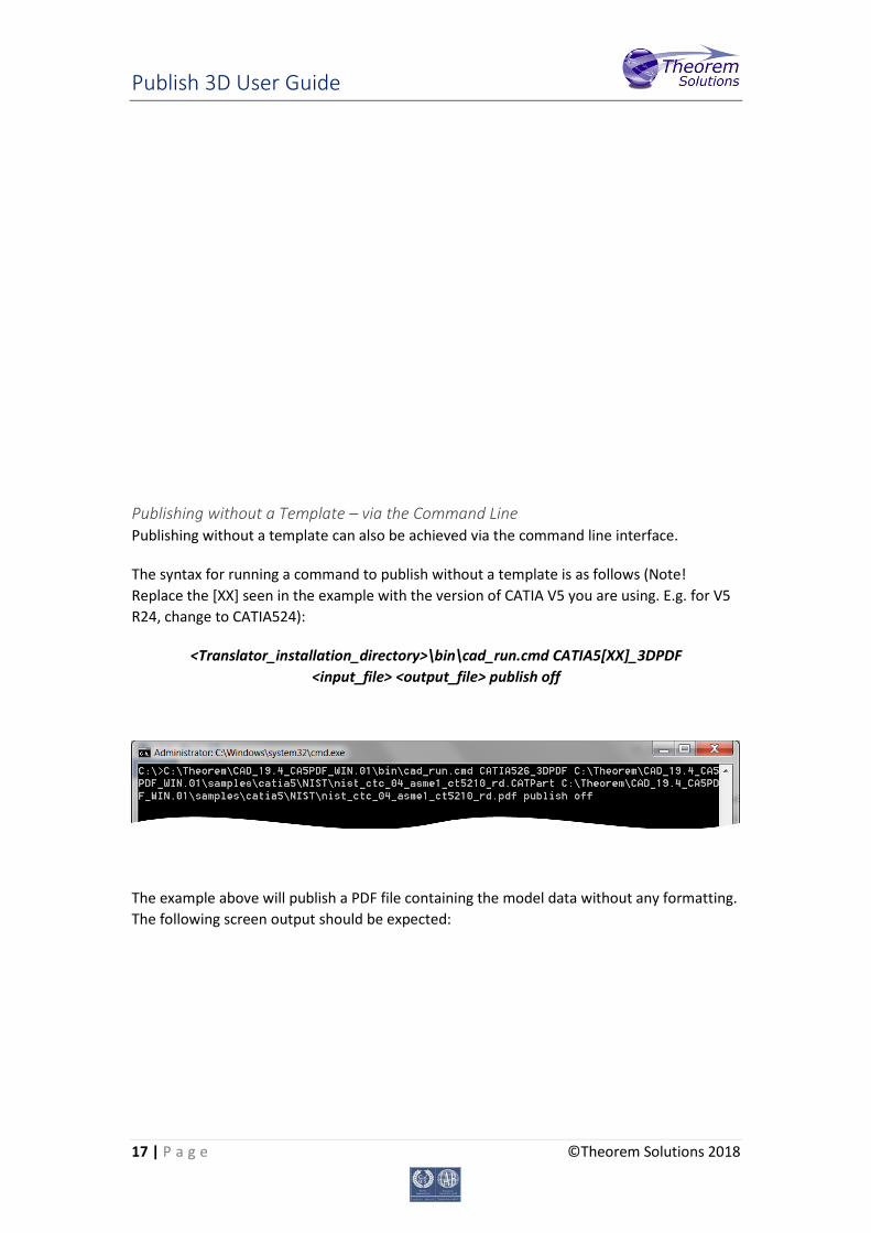
Publishing without a Template – via the Command Line Publishing without a template can also be achieved via the command line interface.
The syntax for running a command to publish without a template is as follows (Note! Replace the [XX] seen in the example with the version of CATIA V5 you are using. E.g. for V5 R24, change to CATIA524):
<Translator_installation_directory>\bin\cad_run.cmd CATIA5[XX]_3DPDF <input_file> <output_file> publish off
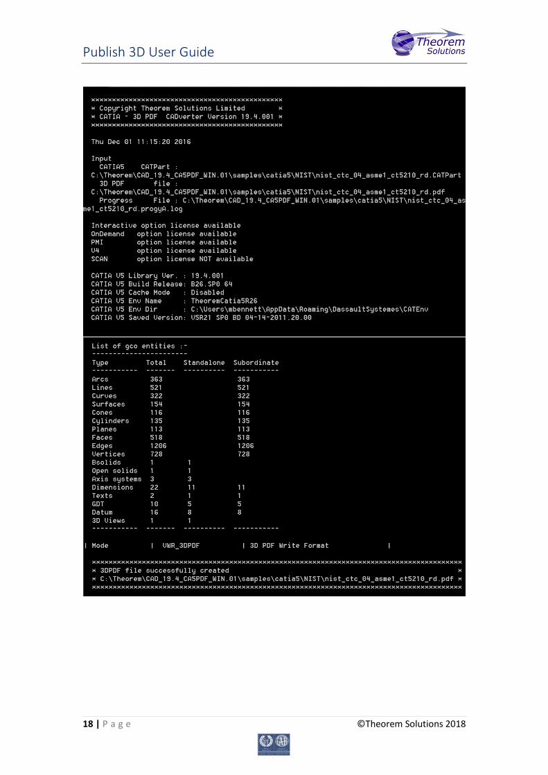
The example above will publish a PDF file containing the model data without any formatting. The following screen output should be expected:
Publish 3D User Guide
18 | P a g e ©Theorem Solutions 2018
Publish 3D User Guide
19 | P a g e ©Theorem Solutions 2018
Publish 3D Customization
Publish 3D allows the information that is read from the source system and written to the target system to be tailored via a set of user specified arguments. Commonly used arguments are supported via the Unified Interface, with Advanced Arguments being described within this document for use in the Unified Interface or via the Command Line invocation.
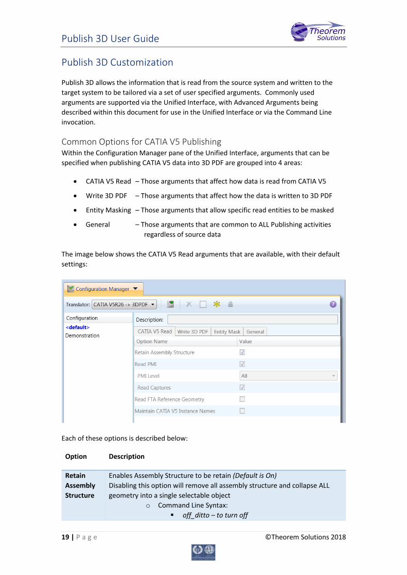
Common Options for CATIA V5 Publishing Within the Configuration Manager pane of the Unified Interface, arguments that can be specified when publishing CATIA V5 data into 3D PDF are grouped into 4 areas:
• CATIA V5 Read – Those arguments that affect how data is read from CATIA V5
• Write 3D PDF – Those arguments that affect how the data is written to 3D PDF
• Entity Masking – Those arguments that allow specific read entities to be masked
• General – Those arguments that are common to ALL Publishing activities regardless of source data
The image below shows the CATIA V5 Read arguments that are available, with their default settings:
Each of these options is described below:
Option Description
Retain Assembly Structure
Enables Assembly Structure to be retain (Default is On) Disabling this option will remove all assembly structure and collapse ALL geometry into a single selectable object
o Command Line Syntax: off_ditto – to turn off

Publish 3D User Guide
20 | P a g e ©Theorem Solutions 2018
Read PMI Enables PMI data read from the V5 file. (Default is ON). o Command Line Syntax:
dont_read_pmi – to turn off
Note! When ‘read_pmi’ is enabled it also enables the ‘fill_pmi_arrows’, ‘fill_pmi_text’ and ‘pmi_filled_text’ options. These can be overridden by setting the Advanced arguments: ‘dont_fill_pmi_arrows’ and/or ‘dont_fill_pmi_text’
PMI Level A secondary argument to ‘Read PMI’ and allows control of the level of PMI to be read. Default is ALL when ‘Read PMI’ is marked as ON.
• Options Available (command line syntax in italics and square brackets next to the option)
o All - [read_pmi] o Part Level - [read_part_pmi] o Assembly Level - [read_assy_pmi] o Assembly Set (From CATPart) - [read_part_assy_pmi] o Assembly Set (All) - [read_all_assy_pmi]
Read Captures
A secondary argument to ‘Read PMI’ and allows the control over whether captures are read as part of the process. Default is ON when ‘Read PMI’ is marked as ON.
o Command Line Syntax: read_captures dont_read_captures – to turn off
Read FTA Reference Geometry
Enables reading of FTA Reference Geometry (Default is Off) o Command Line Syntax:
read_geometry – to turn on
Maintain CATIA V5 Instance Names
Honours CATIA V5 Tools->Options->Infrastructure->Product Structure->Nodes Customization panel settings (Default is Off)
o Command Line Syntax: ditto_naming V5 – to turn on
Publish 3D User Guide
21 | P a g e ©Theorem Solutions 2018
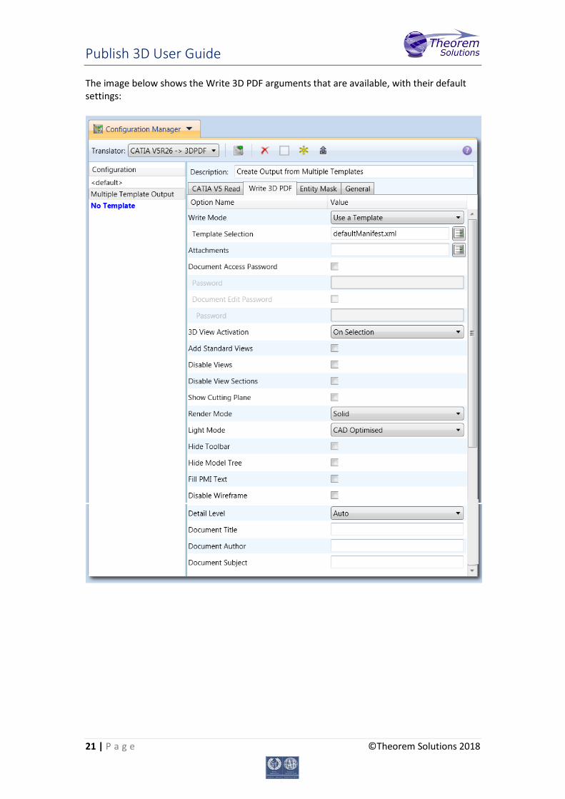
The image below shows the Write 3D PDF arguments that are available, with their default settings:
Publish 3D User Guide
22 | P a g e ©Theorem Solutions 2018
Each of these options is described below:
Option Description
Write Mode
Contains two options: • Use a Template – Allows data to be published to a given
template (Default) o Command Line Syntax:
Publish std <list of Manifest files> • No Template – No template will be used during publishing. If
this option is selected, ‘Template Selection’ is excluded as an option.
o Command Line Syntax: Publish off
Template Selection
Select which templates Publish 3D will use to create the output 3D PDF, if Write Mode is set to Use a Template (Default = defaultManifest.xml)
• Command Line Syntax: o This is a secondary argument to the publish command.
The argument can be a single xml manifest file to a text file containing a list of manifest files
Attachments
This option allows files to be attached to the output PDF file together with a brief description of the selected files. (Default is for no files to be attached)
• Command Line Syntax: o Attach_file <Attachment List>
Where Attachment_List is a list of full path names to file followed by an optional description line: e.g.
C:\TEMP\my_image.jpg This is a jpg Image C:\TEMP\report.txt Report Document C:\TEMP\related.pdf C:\TEMP\another.pdf This PDF has a description
Note in this example the 'Related.pdf' attached file doesn't have the optional comment. The file path may contain environment variables which will be resolved. e.g. %TEMP%/myFile.pdf
Document Access Password
Contains two options selectable via a checkbox: • No Password – Specifies that no password will be used to
encrypt the PDF Document (Default). If this option is selected Password is excluded as an option.
o Command Line Syntax: No entry required
• Use Password – Allow a password to be specified to encrypt the PDF document. If specified, the user will be prompted for the password to open the resultant PDF files
o Command Line Syntax:
Publish 3D User Guide
23 | P a g e ©Theorem Solutions 2018
password <password> Password
Specify what the password is to be used. • Command Line Syntax:
See Document Access Password - This is a secondary argument to this command.
Document Edit Password
Contains two options selectable via a checkbox: • No Password – Specifies that no password will be used to
controls edits to the PDF Document (Default). If this option is selected Password is excluded as an option.
o Command Line Syntax: No entry required
• Use Password – Allow a password to be specified to controls edits to the PDF Document.
o Command Line Syntax: permission_password <password>
Password
Specify what the password is to be used. • Command Line Syntax:
See Document Edit Password - This is a secondary argument to this command.
3D View Activation
Controls when the 3D view is activated in the PDF document. Has 3 options:
• Automatic – Activates when the page is opened. (Default) o Command Line Syntax:
Activate_mode PAGE_OPEN • On Selection – Activates when the user clicks on the model.
o Command Line Syntax: Activate_mode CLICK (default via the
command line) • Page Visible – Activates when the page becomes visible to the
user o Command Line Syntax:
Activate_mode PAGE_VISIBLE Add Standard Views
Add isometric views to the data being written to PDF (Default is off) o Command Line Syntax:
add_standard_views Disable Views
Switch off any Captures/Views from being written into the PDF. (Default is off)
o Command Line Syntax: no_views
Disable View Sections
Switch off any sections within the Captures/Views from being written into the PDF. (Default is off)
o Command Line Syntax: no_sections
Show Cutting Plane
Enable cut plane visualization. (Default is off) o Command Line Syntax:
cutplane_on
Publish 3D User Guide
24 | P a g e ©Theorem Solutions 2018
Render Mode
Controls which Rendering Mode to use for the model. Options are: • Solid (Default) • Transparent • Wire • Illustrated • Outline • Shaded
o Command Line Syntax: Render_mode <mode> Where mode is set to one of the above values
Light Mode
Controls which Light Mode to use. Options are: • Default • Off • Day • Bright • Prim • Night • Blue • Red • Cube • Head
o Command Line Syntax: light_mode <mode> Where mode is set to one of the above values. Note! No command is required for the default value.
Hide Toolbar
Hide the 3D Toolbar in the resultant document. This can be re-enabled in Adobe if required. (Default is off)
o Command Line Syntax: hide_toolbar
Hide Model Tree
Hide the Model Tree in the resultant document. This can be re-enabled in Adobe if required. (Default is off)
o Command Line Syntax: hide_model_tree
Fill PMI Text Create filled fonts for PMI (Default is off) o Command Line Syntax:
pmi_filled_text on Disable Wireframe
Disable Wireframe Processing (Default is to Enable Wireframe processing)
o Command Line Syntax: process_wf off
Detail Level The Detail Level option can be used to set the render quality of the resultant 3D PDF output. A number of discrete values are made available via the UI. They correspond to a relative chordal deviation (% of the diagonal length across the model bounding box) or absolute
Publish 3D User Guide
25 | P a g e ©Theorem Solutions 2018
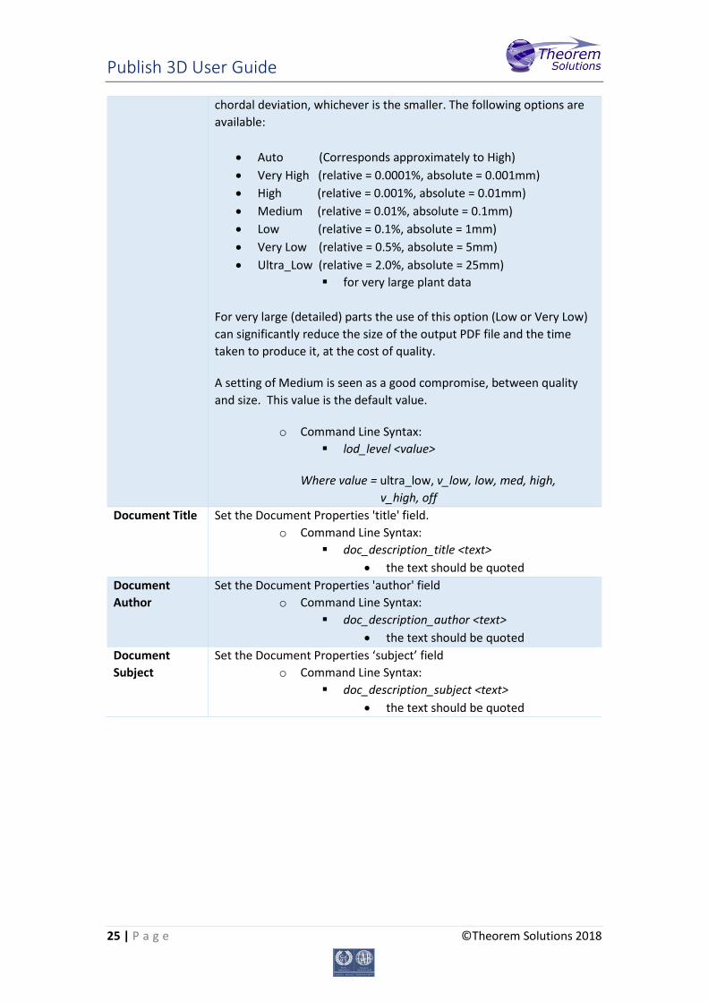
chordal deviation, whichever is the smaller. The following options are available:
• Auto (Corresponds approximately to High) • Very High (relative = 0.0001%, absolute = 0.001mm) • High (relative = 0.001%, absolute = 0.01mm) • Medium (relative = 0.01%, absolute = 0.1mm) • Low (relative = 0.1%, absolute = 1mm) • Very Low (relative = 0.5%, absolute = 5mm) • Ultra_Low (relative = 2.0%, absolute = 25mm)
for very large plant data For very large (detailed) parts the use of this option (Low or Very Low) can significantly reduce the size of the output PDF file and the time taken to produce it, at the cost of quality.
A setting of Medium is seen as a good compromise, between quality and size. This value is the default value.
o Command Line Syntax: lod_level <value>
Where value = ultra_low, v_low, low, med, high, v_high, off
Document Title Set the Document Properties 'title' field. o Command Line Syntax:
doc_description_title <text> • the text should be quoted
Document Author
Set the Document Properties 'author' field o Command Line Syntax:
doc_description_author <text> • the text should be quoted
Document Subject
Set the Document Properties ‘subject’ field o Command Line Syntax:
doc_description_subject <text> • the text should be quoted
Publish 3D User Guide
26 | P a g e ©Theorem Solutions 2018
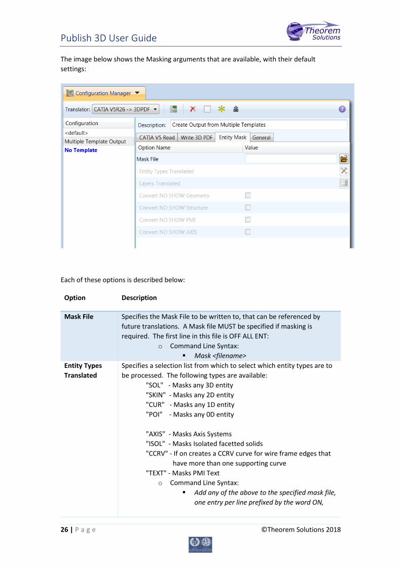
The image below shows the Masking arguments that are available, with their default settings:
Each of these options is described below:
Option Description
Mask File
Specifies the Mask File to be written to, that can be referenced by future translations. A Mask file MUST be specified if masking is required. The first line in this file is OFF ALL ENT:
o Command Line Syntax: Mask <filename>
Entity Types Translated
Specifies a selection list from which to select which entity types are to be processed. The following types are available:
"SOL" - Masks any 3D entity "SKIN" - Masks any 2D entity "CUR" - Masks any 1D entity "POI" - Masks any 0D entity "AXIS" - Masks Axis Systems "ISOL" - Masks Isolated facetted solids "CCRV" - If on creates a CCRV curve for wire frame edges that have more than one supporting curve "TEXT" - Masks PMI Text
o Command Line Syntax: Add any of the above to the specified mask file,
one entry per line prefixed by the word ON,
Publish 3D User Guide
27 | P a g e ©Theorem Solutions 2018
e.g.: ON POI to ensure they are considered in the translation
Layers Translated
Specifies a selection list from which to select which layers are to be processed.
o Command Line Syntax: A single entry of ON ALL LAY Must precede any
Layer Mask command. Add a list or range of numbers representing
layer to be processed to the specified mask file to ensure they are NOT considered in the translation e.g.: OFF LAY 114,149,166,167,168
Convert No Show Geometry
Enables Hidden geometry to be processed (Default = Off) o Command Line Syntax:
Add the following entry to the Mask file ON NOSHOW GEO
Convert No Show Structure
Enables Hidden Assembly Structure to be processed (Default = Off) o Command Line Syntax:
Add the following entry to the Mask file ON NOSHOW STR
Convert No Show PMI
Enables Hidden PMI to be processed (Default = Off) o Command Line Syntax:
Add the following entry to the Mask file ON NOSHOW PMI
Convert No Show AXIS
Enables Hidden Axis Systems to be processed (Default = Off) o Command Line Syntax:
Add the following entry to the Mask file ON NOSHOW AXI
Publish 3D User Guide
28 | P a g e ©Theorem Solutions 2018
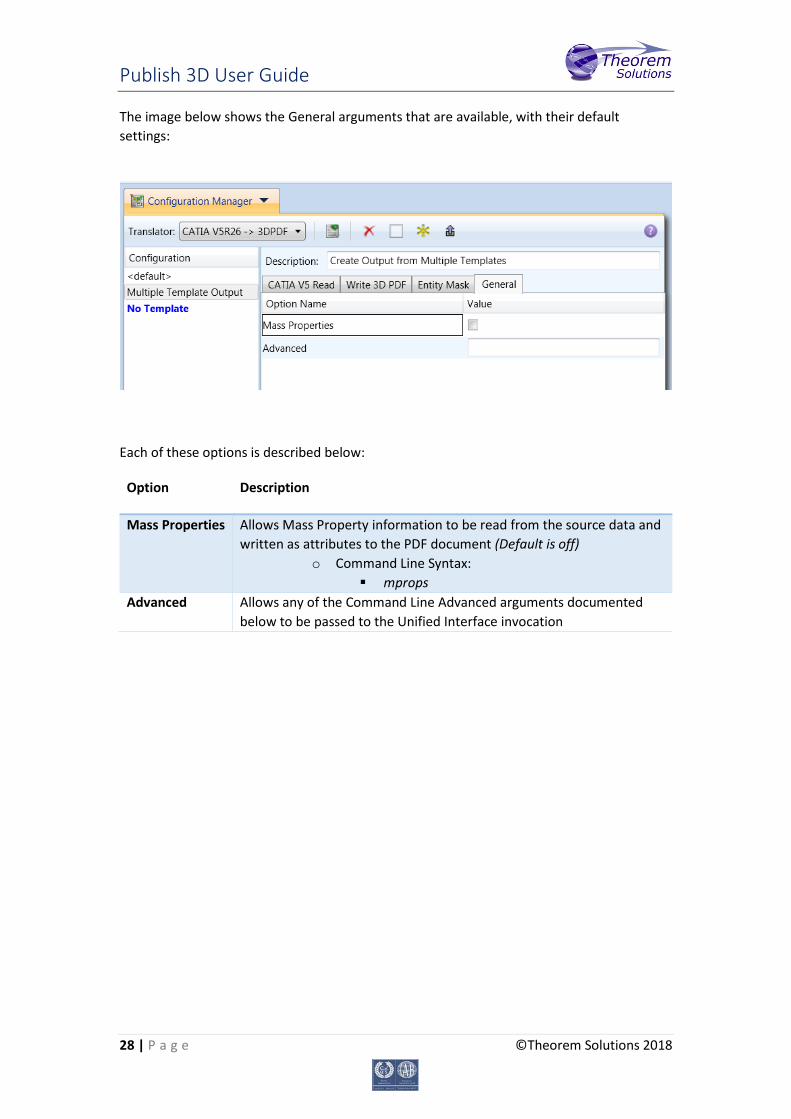
The image below shows the General arguments that are available, with their default settings:
Each of these options is described below:
Option Description
Mass Properties
Allows Mass Property information to be read from the source data and written as attributes to the PDF document (Default is off)
o Command Line Syntax: mprops
Advanced Allows any of the Command Line Advanced arguments documented below to be passed to the Unified Interface invocation
Publish 3D User Guide
29 | P a g e ©Theorem Solutions 2018
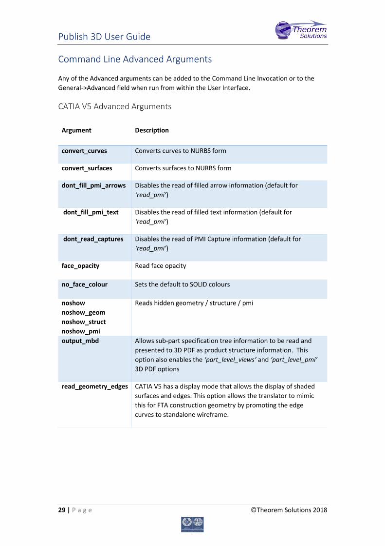
Command Line Advanced Arguments
Any of the Advanced arguments can be added to the Command Line Invocation or to the General->Advanced field when run from within the User Interface.
CATIA V5 Advanced Arguments
Argument Description
convert_curves Converts curves to NURBS form
convert_surfaces Converts surfaces to NURBS form
dont_fill_pmi_arrows Disables the read of filled arrow information (default for ‘read_pmi’)
dont_fill_pmi_text Disables the read of filled text information (default for ‘read_pmi’)
dont_read_captures Disables the read of PMI Capture information (default for ‘read_pmi’)
face_opacity Read face opacity
no_face_colour Sets the default to SOLID colours
noshow noshow_geom noshow_struct noshow_pmi
Reads hidden geometry / structure / pmi
output_mbd Allows sub-part specification tree information to be read and presented to 3D PDF as product structure information. This option also enables the ‘part_level_views’ and ‘part_level_pmi’ 3D PDF options
read_geometry_edges CATIA V5 has a display mode that allows the display of shaded surfaces and edges. This option allows the translator to mimic this for FTA construction geometry by promoting the edge curves to standalone wireframe.
Publish 3D User Guide
30 | P a g e ©Theorem Solutions 2018
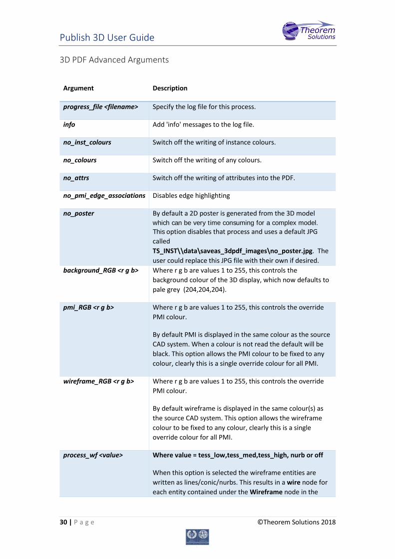
3D PDF Advanced Arguments
Argument Description
progress_file <filename> Specify the log file for this process.
info Add 'info' messages to the log file.
no_inst_colours Switch off the writing of instance colours.
no_colours Switch off the writing of any colours.
no_attrs Switch off the writing of attributes into the PDF.
no_pmi_edge_associations Disables edge highlighting
no_poster By default a 2D poster is generated from the 3D model which can be very time consuming for a complex model. This option disables that process and uses a default JPG called TS_INST\\data\saveas_3dpdf_images\no_poster.jpg. The user could replace this JPG file with their own if desired.
background_RGB <r g b> Where r g b are values 1 to 255, this controls the background colour of the 3D display, which now defaults to pale grey (204,204,204).
pmi_RGB <r g b> Where r g b are values 1 to 255, this controls the override PMI colour.
By default PMI is displayed in the same colour as the source CAD system. When a colour is not read the default will be black. This option allows the PMI colour to be fixed to any colour, clearly this is a single override colour for all PMI.
wireframe_RGB <r g b> Where r g b are values 1 to 255, this controls the override PMI colour.
By default wireframe is displayed in the same colour(s) as the source CAD system. This option allows the wireframe colour to be fixed to any colour, clearly this is a single override colour for all PMI.
process_wf <value> Where value = tess_low,tess_med,tess_high, nurb or off
When this option is selected the wireframe entities are written as lines/conic/nurbs. This results in a wire node for each entity contained under the Wireframe node in the
Publish 3D User Guide
31 | P a g e ©Theorem Solutions 2018
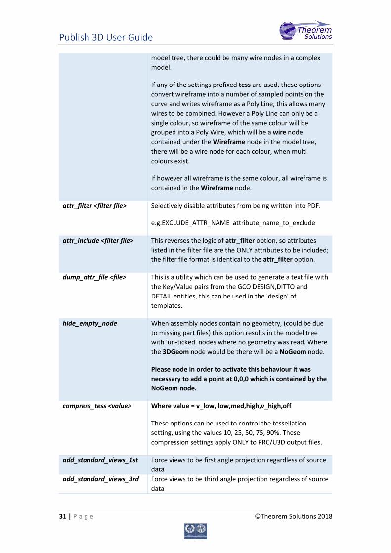
model tree, there could be many wire nodes in a complex model.
If any of the settings prefixed tess are used, these options convert wireframe into a number of sampled points on the curve and writes wireframe as a Poly Line, this allows many wires to be combined. However a Poly Line can only be a single colour, so wireframe of the same colour will be grouped into a Poly Wire, which will be a wire node contained under the Wireframe node in the model tree, there will be a wire node for each colour, when multi colours exist.
If however all wireframe is the same colour, all wireframe is contained in the Wireframe node.
attr_filter <filter file> Selectively disable attributes from being written into PDF.
e.g.EXCLUDE_ATTR_NAME attribute_name_to_exclude
attr_include <filter file> This reverses the logic of attr_filter option, so attributes listed in the filter file are the ONLY attributes to be included; the filter file format is identical to the attr_filter option.
dump_attr_file <file> This is a utility which can be used to generate a text file with the Key/Value pairs from the GCO DESIGN,DITTO and DETAIL entities, this can be used in the 'design' of templates.
hide_empty_node When assembly nodes contain no geometry, (could be due to missing part files) this option results in the model tree with 'un-ticked' nodes where no geometry was read. Where the 3DGeom node would be there will be a NoGeom node.
Please node in order to activate this behaviour it was necessary to add a point at 0,0,0 which is contained by the NoGeom node.
compress_tess <value> Where value = v_low, low,med,high,v_high,off
These options can be used to control the tessellation setting, using the values 10, 25, 50, 75, 90%. These compression settings apply ONLY to PRC/U3D output files.
add_standard_views_1st Force views to be first angle projection regardless of source data
add_standard_views_3rd Force views to be third angle projection regardless of source data
Publish 3D User Guide
32 | P a g e ©Theorem Solutions 2018
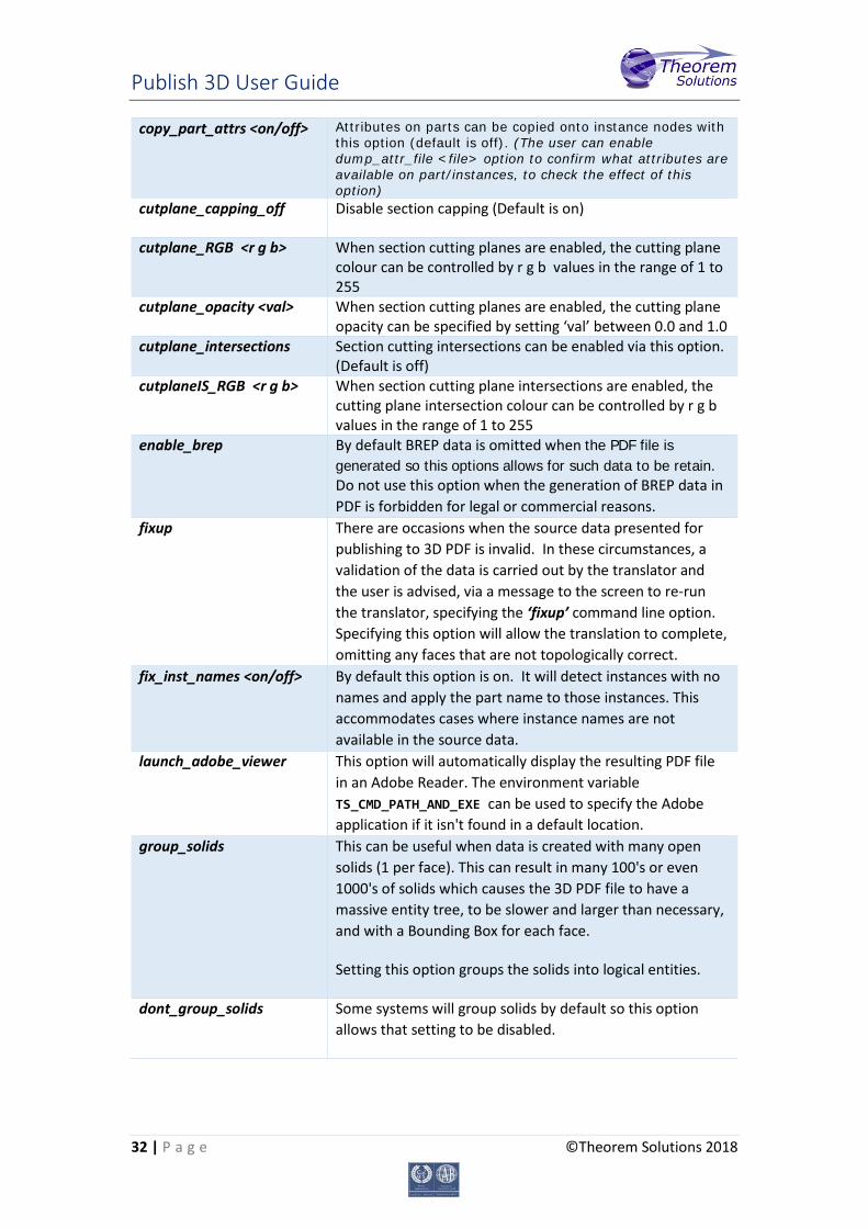
copy_part_attrs <on/off> Attributes on parts can be copied onto instance nodes with this option (default is off). (The user can enable dump_attr_file <file> option to confirm what attributes are available on part/instances, to check the effect of this option)
cutplane_capping_off Disable section capping (Default is on)
cutplane_RGB <r g b> When section cutting planes are enabled, the cutting plane colour can be controlled by r g b values in the range of 1 to 255
cutplane_opacity <val> When section cutting planes are enabled, the cutting plane opacity can be specified by setting ‘val’ between 0.0 and 1.0
cutplane_intersections Section cutting intersections can be enabled via this option. (Default is off)
cutplaneIS_RGB <r g b> When section cutting plane intersections are enabled, the cutting plane intersection colour can be controlled by r g b values in the range of 1 to 255
enable_brep By default BREP data is omitted when the PDF file is generated so this options allows for such data to be retain. Do not use this option when the generation of BREP data in PDF is forbidden for legal or commercial reasons.
fixup There are occasions when the source data presented for publishing to 3D PDF is invalid. In these circumstances, a validation of the data is carried out by the translator and the user is advised, via a message to the screen to re-run the translator, specifying the ‘fixup’ command line option. Specifying this option will allow the translation to complete, omitting any faces that are not topologically correct.
fix_inst_names <on/off> By default this option is on. It will detect instances with no names and apply the part name to those instances. This accommodates cases where instance names are not available in the source data.
launch_adobe_viewer This option will automatically display the resulting PDF file in an Adobe Reader. The environment variable TS_CMD_PATH_AND_EXE can be used to specify the Adobe application if it isn't found in a default location.
group_solids This can be useful when data is created with many open solids (1 per face). This can result in many 100's or even 1000's of solids which causes the 3D PDF file to have a massive entity tree, to be slower and larger than necessary, and with a Bounding Box for each face.
Setting this option groups the solids into logical entities.
dont_group_solids Some systems will group solids by default so this option allows that setting to be disabled.
Publish 3D User Guide
33 | P a g e ©Theorem Solutions 2018
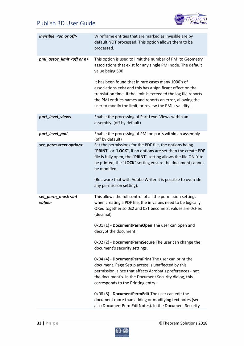
invisible <on or off>
Wireframe entities that are marked as invisible are by default NOT processed. This option allows them to be processed.
pmi_assoc_limit <off or n> This option is used to limit the number of PMI to Geometry associations that exist for any single PMI node. The default value being 500.
It has been found that in rare cases many 1000's of associations exist and this has a significant effect on the translation time. If the limit is exceeded the log file reports the PMI entities names and reports an error, allowing the user to modify the limit, or review the PMI's validity.
part_level_views Enable the processing of Part Level Views within an assembly. (off by default)
part_level_pmi Enable the processing of PMI on parts within an assembly (off by default)
set_perm <text option> Set the permissions for the PDF file, the options being "PRINT" or "LOCK", if no options are set then the create PDF file is fully open, the "PRINT" setting allows the file ONLY to be printed, the "LOCK" setting ensure the document cannot be modified.
(Be aware that with Adobe Writer it is possible to override any permission setting).
set_perm_mask <int value>
This allows the full control of all the permission settings when creating a PDF file, the in values need to be logically ORed together so 0x2 and 0x1 become 3. values are 0xHex (decimal)
0x01 (1) - DocumentPermOpen The user can open and decrypt the document.
0x02 (2) - DocumentPermSecure The user can change the document's security settings.
0x04 (4) - DocumentPermPrint The user can print the document. Page Setup access is unaffected by this permission, since that affects Acrobat's preferences - not the document's. In the Document Security dialog, this corresponds to the Printing entry.
0x08 (8) - DocumentPermEdit The user can edit the document more than adding or modifying text notes (see also DocumentPermEditNotes). In the Document Security
Publish 3D User Guide
34 | P a g e ©Theorem Solutions 2018
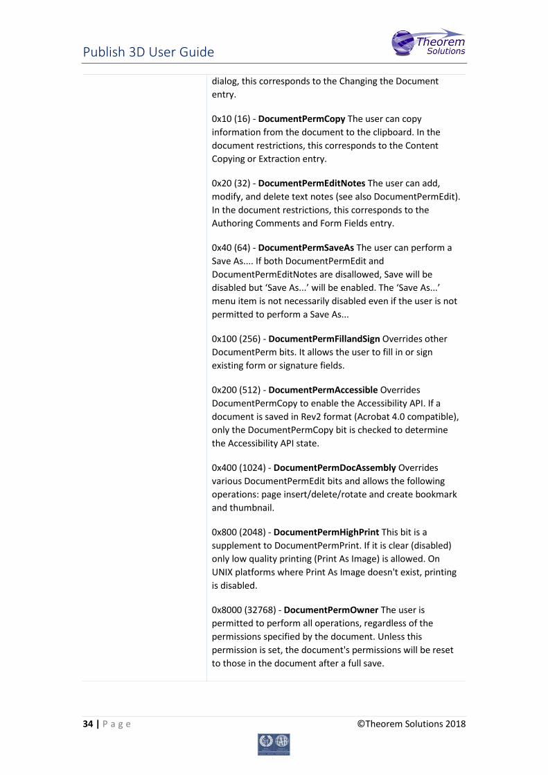
dialog, this corresponds to the Changing the Document entry.
0x10 (16) - DocumentPermCopy The user can copy information from the document to the clipboard. In the document restrictions, this corresponds to the Content Copying or Extraction entry.
0x20 (32) - DocumentPermEditNotes The user can add, modify, and delete text notes (see also DocumentPermEdit). In the document restrictions, this corresponds to the Authoring Comments and Form Fields entry.
0x40 (64) - DocumentPermSaveAs The user can perform a Save As.... If both DocumentPermEdit and DocumentPermEditNotes are disallowed, Save will be disabled but ‘Save As...’ will be enabled. The ‘Save As...’ menu item is not necessarily disabled even if the user is not permitted to perform a Save As...
0x100 (256) - DocumentPermFillandSign Overrides other DocumentPerm bits. It allows the user to fill in or sign existing form or signature fields.
0x200 (512) - DocumentPermAccessible Overrides DocumentPermCopy to enable the Accessibility API. If a document is saved in Rev2 format (Acrobat 4.0 compatible), only the DocumentPermCopy bit is checked to determine the Accessibility API state.
0x400 (1024) - DocumentPermDocAssembly Overrides various DocumentPermEdit bits and allows the following operations: page insert/delete/rotate and create bookmark and thumbnail.
0x800 (2048) - DocumentPermHighPrint This bit is a supplement to DocumentPermPrint. If it is clear (disabled) only low quality printing (Print As Image) is allowed. On UNIX platforms where Print As Image doesn't exist, printing is disabled.
0x8000 (32768) - DocumentPermOwner The user is permitted to perform all operations, regardless of the permissions specified by the document. Unless this permission is set, the document's permissions will be reset to those in the document after a full save.
Publish 3D User Guide
35 | P a g e ©Theorem Solutions 2018
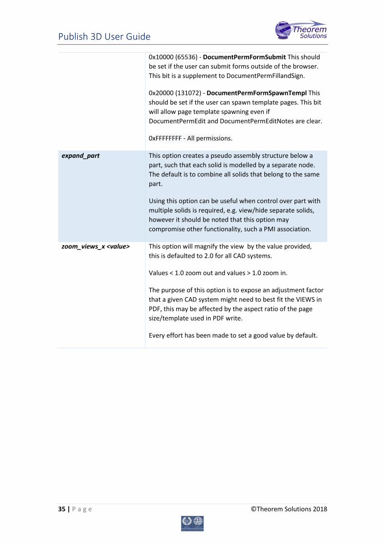
0x10000 (65536) - DocumentPermFormSubmit This should be set if the user can submit forms outside of the browser. This bit is a supplement to DocumentPermFillandSign.
0x20000 (131072) - DocumentPermFormSpawnTempl This should be set if the user can spawn template pages. This bit will allow page template spawning even if DocumentPermEdit and DocumentPermEditNotes are clear.
0xFFFFFFFF - All permissions.
expand_part This option creates a pseudo assembly structure below a part, such that each solid is modelled by a separate node. The default is to combine all solids that belong to the same part.
Using this option can be useful when control over part with multiple solids is required, e.g. view/hide separate solids, however it should be noted that this option may compromise other functionality, such a PMI association.
zoom_views_x <value> This option will magnify the view by the value provided, this is defaulted to 2.0 for all CAD systems.
Values < 1.0 zoom out and values > 1.0 zoom in.
The purpose of this option is to expose an adjustment factor that a given CAD system might need to best fit the VIEWS in PDF, this may be affected by the aspect ratio of the page size/template used in PDF write.
Every effort has been made to set a good value by default.
Publish 3D User Guide
36 | P a g e ©Theorem Solutions 2018
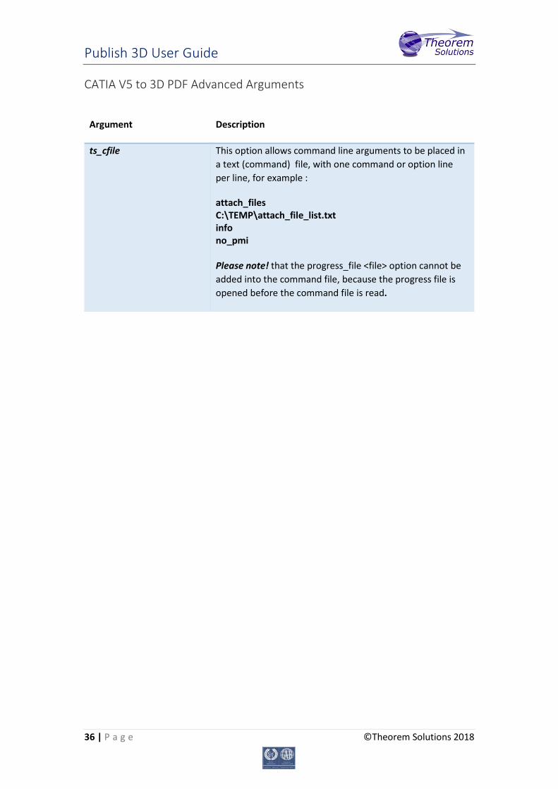
CATIA V5 to 3D PDF Advanced Arguments
Argument Description
ts_cfile This option allows command line arguments to be placed in a text (command) file, with one command or option line per line, for example :
attach_files C:\TEMP\attach_file_list.txt info no_pmi Please note! that the progress_file <file> option cannot be added into the command file, because the progress file is opened before the command file is read.
Publish 3D User Guide
37 | P a g e ©Theorem Solutions 2018
Publish 3D Interactive
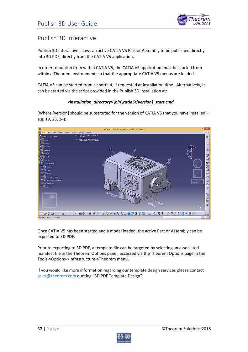
Publish 3D Interactive allows an active CATIA V5 Part or Assembly to be published directly into 3D PDF, directly from the CATIA V5 application.
In order to publish from within CATIA V5, the CATIA V5 application must be started from within a Theorem environment, so that the appropriate CATIA V5 menus are loaded.
CATIA V5 can be started from a shortcut, if requested at installation time. Alternatively, it can be started via the script provided in the Publish 3D installation at:
<installation_directory>\bin\catia5r[version]_start.cmd
(Where [version] should be substituted for the version of CATIA V5 that you have installed – e.g. 19, 23, 24):
Once CATIA V5 has been started and a model loaded, the active Part or Assembly can be exported to 3D PDF. Prior to exporting to 3D PDF, a template file can be targeted by selecting an associated manifest file in the Theorem Options panel, accessed via the Theorem Options page in the Tools->Options->Infrastructure->Theorem menu. If you would like more information regarding our template design services please contact [email protected] quoting “3D PDF Template Design”.

Publish 3D User Guide
38 | P a g e ©Theorem Solutions 2018
From this Panel, the user can select a predefined configuration, whether a password should be set, the default directory for log file creation and whether the PDF document is opened once created. After these options are set, the active Part or Assembly can be saved to 3D PDF, via the File->SaveAs menu option:
On selecting ‘Save’ the active Part or Assembly will be written to 3D PDF using the preselected template as the output document format, in the selected output directory.
Publish 3D User Guide
39 | P a g e ©Theorem Solutions 2018
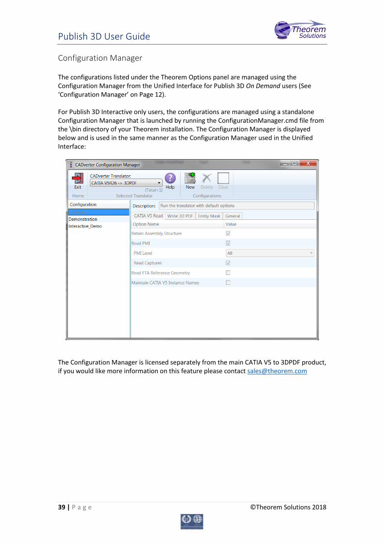
Configuration Manager The configurations listed under the Theorem Options panel are managed using the Configuration Manager from the Unified Interface for Publish 3D On Demand users (See ‘Configuration Manager’ on Page 12). For Publish 3D Interactive only users, the configurations are managed using a standalone Configuration Manager that is launched by running the ConfigurationManager.cmd file from the \bin directory of your Theorem installation. The Configuration Manager is displayed below and is used in the same manner as the Configuration Manager used in the Unified Interface:
The Configuration Manager is licensed separately from the main CATIA V5 to 3DPDF product, if you would like more information on this feature please contact [email protected]
Publish 3D User Guide
40 | P a g e ©Theorem Solutions 2018
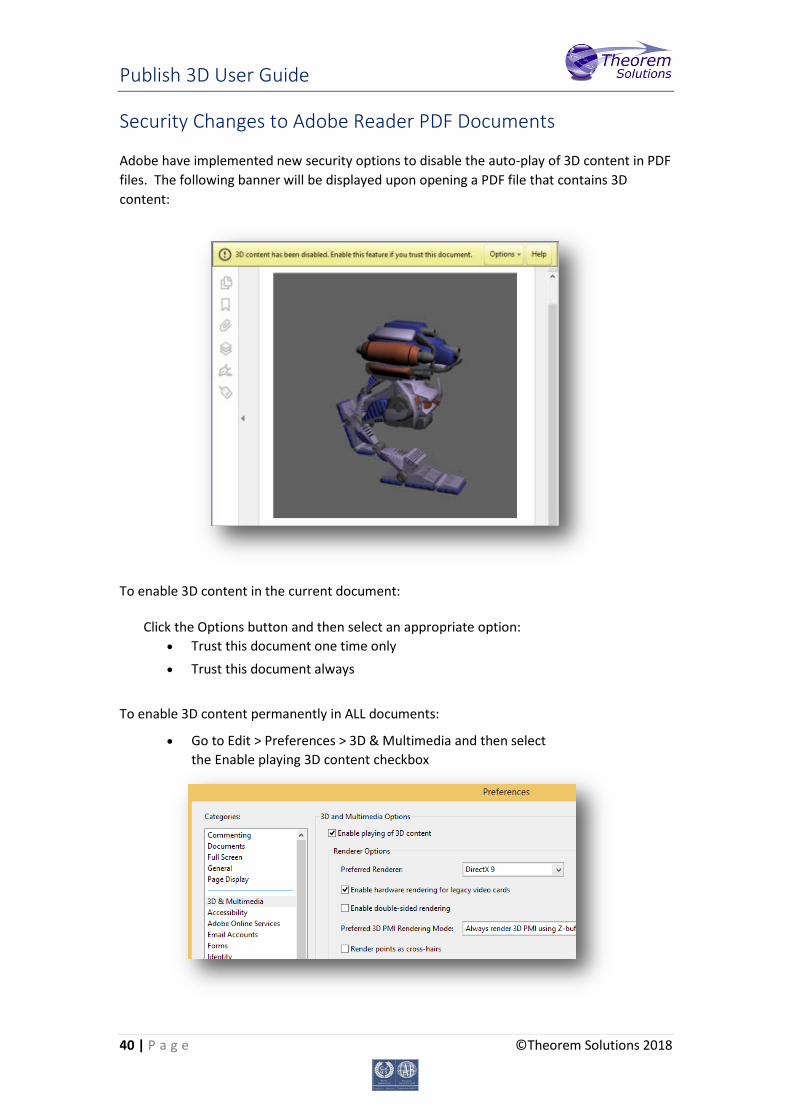
Security Changes to Adobe Reader PDF Documents
Adobe have implemented new security options to disable the auto-play of 3D content in PDF files. The following banner will be displayed upon opening a PDF file that contains 3D content:
To enable 3D content in the current document:
Click the Options button and then select an appropriate option: • Trust this document one time only • Trust this document always
To enable 3D content permanently in ALL documents:
• Go to Edit > Preferences > 3D & Multimedia and then select the Enable playing 3D content checkbox