Public Infrastructure Design Standards -...
33
September 2017 Public Infrastructure Design Standards Department of Public Works
Transcript of Public Infrastructure Design Standards -...

September 2017
Public Infrastructure Design Standards
Department of Public Works
1 | P a g e
Public Infrastructure Design Standards Purpose: These standards are meant to provide uniform design and construction specifications to establish standard construction materials and methods for the Lafayette City-Parish Consolidated Government (LCG). Any deviation from these standards shall be approved by the Director of the Department of Public Works (or his/her designee), in writing, in advance of any construction.
Contents
Section Page
References 2
Applicability 2
I. General Standards 3
II. Design Standards
A. Hydrology Standards 3 B. Hydraulic Standards 5 C. Hydraulic Standards for the Designated 100 Year Flood Hazard Area 7 D. Traffic Standards 8 E. Roadway Standards 14
III. Submittal Requirements 21
IV. Waivers 23
V. Certifications 23
Appendix A 25
Appendix B 28
Appendix C 29

2 | P a g e
References In accordance with the provisions of Revised Statutes of 1950, Title 33: 101-119 of the State of Louisiana, as amended, in order to promote the health, safety, convenience, and general welfare of the inhabitants of Lafayette Parish and to assist in bringing about the coordinated, efficient, and economical development of the Parish, the following are the regulations and minimum standards for LCG. The following agencies, publications and policies are hereby referenced as applicable standards to supplement this document:
• American Association of State Highway and Transportation Officials (AASHTO) A Policy on Geometric Design of Highways and Streets
• Americans with Disabilities Act Standards for Accessible Design (ADA)
• Department of Environmental Quality (DEQ)
• Department of Transportation and Development (DOTD) publications
• Environmental Protection Agency (EPA)
• Federal Emergency Management Agency (FEMA) publications and applicable Code of Federal Regulations (CFR)
• National Flood Insurance Program (NFIP)
• National Bridge Inspection Program (NBIP)
• Federal Highway Administration (FHWA)
• Institute of Transportation Engineers Trip Generation Manual (ITE)
• Lafayette Utilities Systems (LUS), Standards for Arterial Street Lighting
• Publications from Illuminating Engineering Society of North America, roadway lighting
• LCG’s Specifications for Roads, Drainage, Bridges and Other Infrastructure Improvements, LCG Standard Details, LCG Street Cut Detail, LCG Driveway Detail
• Manual on Uniform Traffic Control Devices (MUTCD)
• Transportation Research Board’s Highway Capacity Manual
• Unified Development Code (UDC)
Applicability 1) All standards herein apply to the development standards for projects designed and constructed by
private developers in anticipation of LCG acceptance of the dedicated public infrastructure. Failure to adhere to these standards will prevent the acceptance of the public infrastructure by LCG.
2) All standards herein apply to the development standards for the public infrastructure connections and the retention requirements for projects designed and constructed by private developers for the private use of the developer. Failure to adhere to these standards will prevent approval of a final plat recordation or a building permit.
3) All standards herein apply to the development standards for projects designed and constructed by LCG.
3 | P a g e
I. General Standards 1) All infrastructure anticipated to be accepted by LCG shall be designed by a licensed professional
engineer registered in the State of Louisiana.
2) All public infrastructure shall be constructed in accordance with LCG’s Standard Details, Specifications for Roads, Drainage, Bridges and Other Infrastructure Improvements and LUS requirements.
3) All equipment, materials, and products shall be installed, at minimum, in accordance with the instructions of the manufacturers.
4) Any and all public infrastructure, including, but not limited to, sidewalks, roadways, drainage, catch-basins, damaged during development is the sole responsibility of the developer. In the event public infrastructure is damaged during development, a certificate of occupancy will not be issued until satisfactory repairs are completed to LCG standards.
II. Design Standards A. Hydrology Standards
1) Drainage Area and Design: the Design Engineer shall make provision in the drainage improvements for each development to accommodate potential storm-water runoff from its entire upstream drainage area, whether inside or outside of the development/project. Additionally, the Design Engineer shall study the effect of each development/project on existing downstream drainage facilities or roadside ditches outside the area of the development for no less than 1000’ of the effluent channel downstream of the development/project. Where it is anticipated that the runoff incident of the development/project will overload an existing downstream drainage facility or roadside ditch, the Design Engineer shall indicate this fact in the development/project drainage design and make provisions to prevent the overloading of downstream facilities or roadside ditches, regardless of the size of the development.
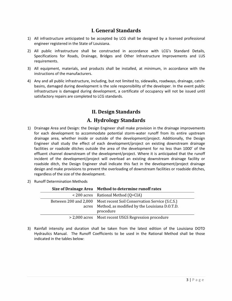
2) Runoff Determination Methods
Size of Drainage Area Method to determine runoff rates < 200 acres Rational Method (Q=CIA)
Between 200 and 2,000 acres
Most recent Soil Conservation Service (S.C.S.) Method, as modified by the Louisiana D.O.T.D. procedure
> 2,000 acres Most recent USGS Regression procedure
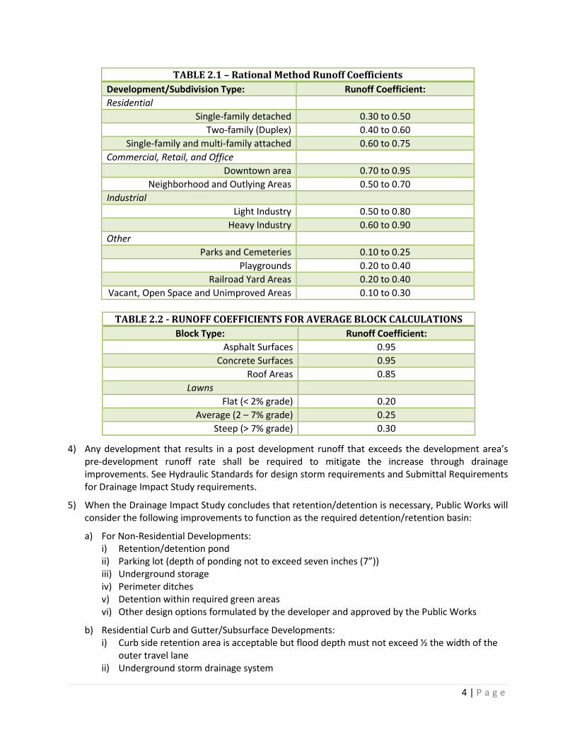
3) Rainfall intensity and duration shall be taken from the latest edition of the Louisiana DOTD Hydraulics Manual. The Runoff Coefficients to be used in the Rational Method shall be those indicated in the tables below:
4 | P a g e
TABLE 2.1 – Rational Method Runoff Coefficients Development/Subdivision Type: Runoff Coefficient: Residential
Single-family detached 0.30 to 0.50 Two-family (Duplex) 0.40 to 0.60
Single-family and multi-family attached 0.60 to 0.75 Commercial, Retail, and Office
Downtown area 0.70 to 0.95 Neighborhood and Outlying Areas 0.50 to 0.70
Industrial Light Industry 0.50 to 0.80
Heavy Industry 0.60 to 0.90 Other
Parks and Cemeteries 0.10 to 0.25 Playgrounds 0.20 to 0.40
Railroad Yard Areas 0.20 to 0.40 Vacant, Open Space and Unimproved Areas 0.10 to 0.30
4) Any development that results in a post development runoff that exceeds the development area’s pre-development runoff rate shall be required to mitigate the increase through drainage improvements. See Hydraulic Standards for design storm requirements and Submittal Requirements for Drainage Impact Study requirements.
5) When the Drainage Impact Study concludes that retention/detention is necessary, Public Works will consider the following improvements to function as the required detention/retention basin:
a) For Non-Residential Developments: i) Retention/detention pond ii) Parking lot (depth of ponding not to exceed seven inches (7”)) iii) Underground storage iv) Perimeter ditches v) Detention within required green areas vi) Other design options formulated by the developer and approved by the Public Works
b) Residential Curb and Gutter/Subsurface Developments: i) Curb side retention area is acceptable but flood depth must not exceed ½ the width of the
outer travel lane ii) Underground storm drainage system
TABLE 2.2 - RUNOFF COEFFICIENTS FOR AVERAGE BLOCK CALCULATIONS Block Type: Runoff Coefficient:
Asphalt Surfaces 0.95 Concrete Surfaces 0.95
Roof Areas 0.85 Lawns
Flat (< 2% grade) 0.20 Average (2 – 7% grade) 0.25
Steep (> 7% grade) 0.30
5 | P a g e
iii) Retention/detention pond iv) Other design options formulated by the developer and approved by the Public Works
c) Residential Open Ditch Developments (to remain open ditch): i) Retention/detention pond ii) Perimeter ditches when used as an outfall of Public Infrastructure; rear lot or common
property drainage system shall not be an open ditch or drainage swale system iii) Other design options formulated by the developer and approved by the Public Works
Department; roadside ditches, however, are not accepted for retention/detention use where an open ditch development is permitted.
d) In addition to the outlet/control structures for retention/detention, emergency spillways shall be in an area that will least affect traffic flow and not cause flooding of structures intended for occupancy.
B. Hydraulic Standards 1) All drainage systems shall be designed in accordance with the most recent edition of the Louisiana
Department of Transportation and Development’s Hydraulics Manual unless otherwise approved by the Public Works Director (or his/her designee).
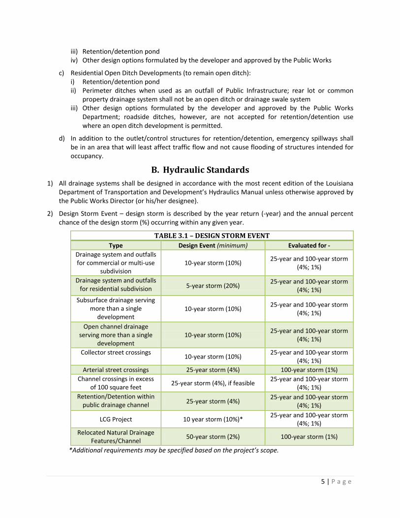
2) Design Storm Event – design storm is described by the year return (-year) and the annual percent chance of the design storm (%) occurring within any given year.
TABLE 3.1 – DESIGN STORM EVENT Type Design Event (minimum) Evaluated for -
Drainage system and outfalls for commercial or multi-use
subdivision 10-year storm (10%) 25-year and 100-year storm
(4%; 1%)
Drainage system and outfalls for residential subdivision 5-year storm (20%) 25-year and 100-year storm
(4%; 1%) Subsurface drainage serving
more than a single development
10-year storm (10%) 25-year and 100-year storm (4%; 1%)
Open channel drainage serving more than a single
development 10-year storm (10%) 25-year and 100-year storm
(4%; 1%)
Collector street crossings 10-year storm (10%) 25-year and 100-year storm (4%; 1%)
Arterial street crossings 25-year storm (4%) 100-year storm (1%) Channel crossings in excess
of 100 square feet 25-year storm (4%), if feasible 25-year and 100-year storm (4%; 1%)
Retention/Detention within public drainage channel 25-year storm (4%) 25-year and 100-year storm
(4%; 1%)
LCG Project 10 year storm (10%)* 25-year and 100-year storm (4%; 1%)
Relocated Natural Drainage Features/Channel 50-year storm (2%) 100-year storm (1%)
*Additional requirements may be specified based on the project’s scope.
6 | P a g e
a) The hydraulic grade line shall be used to determine the extent of flooding, depth of flooding, and efficiency of the system. The hydraulic grade line, as determined through sub-surface system calculations, may inundate ½ the outer travel lane and is inclusive of the detention/retention system (i.e. include pond maximum elevation).
b) Inlet capacity is established for all new public roadways. The maximum depth of flooding for a collector or arterial is ½ the outer travel lane during the design storm. The maximum depth of flooding for residential roadways is the elevation of the centerline of the roadway.
c) The capacity of all existing ditches, culverts, sub-surface and surface drainage structures that will be utilized by new or relocated outfall points downstream of the development to allow passage of storm water to the first outfall, coulee, canal or river shall be determined and analyzed for the development runoff. In no case shall a developer evaluate the capacity of the outfall, coulee, canal or river less than 1,000 feet downstream of the development.
d) Tailwater (TW) is defined as the flow depth of the downstream channel measured from the flow line of the outlet structure or culvert. It is considered to be an important factor in outfall structure or culvert hydraulic design because a submerged outlet may cause structures or culverts to flow full, rather than partially full, impacting the hydraulic efficiency of the drainage system.
i) Therefore, the hydraulic analysis of the drainage system shall address the tailwater elevation of the outfall channel/system.
ii) The tailwater elevation of the outfall channel/system shall be set at 1 foot of freeboard from top bank for open channel systems and/or flowing full for sub-surface drainage systems unless, through a hydraulic analysis for a 25-year design storm event, it is determined to be lower.
3) “Wet” drainage systems are not accepted. A drainage system shall not hold water when there is no storm event. All public inverts are determined by dry conditions.
4) Multi-barrel culverts are not permitted.
5) The cleansing velocity of 3 ft/sec is the desired velocity and must be met within a drainage system. It is understood that the beginning of the system may not achieve this velocity due to the 15” culvert minimum requirement, but shall be achieved within the first 3 structures of the system.
6) Developments for which a subsurface drainage system has hydraulically proven to be impractical will utilize an open ditch drainage design such that:
a) Maximum depth of ditches is limited to thirty inches (30”).
b) Minimum ditch grade along streets is 0.20%, and those ditch grades which directly advance erosion of the ditch or adjacent properties are strictly prohibited.
c) Design is based on culvert flow when culverts are placed within sixty feet (60’) of each other.
7) If a drainage design intends to utilize a pond inside an existing channel, the channel and pond must be designed such that a minimum 25-year storm event can be contained in the channel/pond to prevent damage to upstream properties. In no way shall the flood extents exceed the existing flood hazard area and impact adjacent properties without the full notification and letter of map amendment process as described by FEMA/NFIP regulations.
8) Any channel relocation may not alter the flood hazard limits and impact adjacent properties without the full notification and letter of map amendment process as described by FEMA/NFIP regulations.
7 | P a g e
All channel relocation/improvements must be supported by a Hydraulic Analysis that indicates there is no hydraulic impact outside the platted boundaries for the applicable design storm.
9) Any development that has rear lot drainage that traverses through multiple lots shall be sub-surface.
10) No encroachment of permanent structures are permitted within public drainage servitudes.
11) LCG reserves the right to require information on all developments to ensure future structures are protected from flooding.
C. Hydraulic Standards for the Designated 100 Year Flood Hazard Area 1) The following general standards shall apply in addition to any other stated provisions for all
proposed development within the City and Parish of Lafayette and the designated one percent (1%) chance storm event or one hundred (100) year special flood hazard area:
a) Flood Plain Analysis shall be required for all developments/projects greater than 50 lots or 5 acres, whichever is the lesser, located within a Designated Flood Hazard Zone. The complete analysis must be conducted after Preliminary Plat approval by the Planning Commission and before Final Plat approval or issuance of a commercial building permit.
b) Any Flood Plain Impact Analysis conducted for a development/project located in the Designated Flood Hazard Area Zone “A” shall include, as an integral part of the Flood Plain Impact Analysis, a Base Flood Elevation Determination in accordance with the FEMA NFIP document, “Managing Floodplain Development in Approximate Zone A Areas.”
c) No development, fill, or obstruction of any type on or over any portion of a Designated Floodway shall be permitted which alone or cumulatively with other such development, fill, or obstructions would cause or result in an obstruction or otherwise adversely affect the efficiency of or restrict the flow or capacity of a Designated Floodway so as to cause foreseeable damage to others, wherever located. Any such development application shall include hydrologic and hydraulic HEC-RAS data (or other models acceptable to the applicable regulatory agency) confirming that no adverse flood effects will result from a proposed development in the Designated Floodway. This certification is subject to review and approval or denial by the Lafayette Consolidated Government Floodplain Administrator and/or FEMA.
d) Fill or other materials placed within a known flood hazard area or flood plain area shall be protected against erosion. Acceptable means of protection include, but are not limited to: Rip-rap, vegetation covers, hydro-mulch, erosion control matting and bulk heading. See above for more information on proposed fill in floodways as defined by the latest NFIP F.I.R.M.
e) Elevation Requirements – all structures or applicable public infrastructure enclosed on three or more sides, built on property in the one hundred (100) year Flood Zone shall be elevated to ensure the lowest floor elevation is located at a minimum of one foot (1’) above the base flood elevation height for that area at the time of project construction.
2) Public Works will review all submitted data as the technical representative for the Floodplain Administrator. If, after a thorough review of the development, the design engineer/developer is not satisfied, LCG will require the developer to submit the required flood hazard documentation directly to FEMA for their response and approval.
8 | P a g e
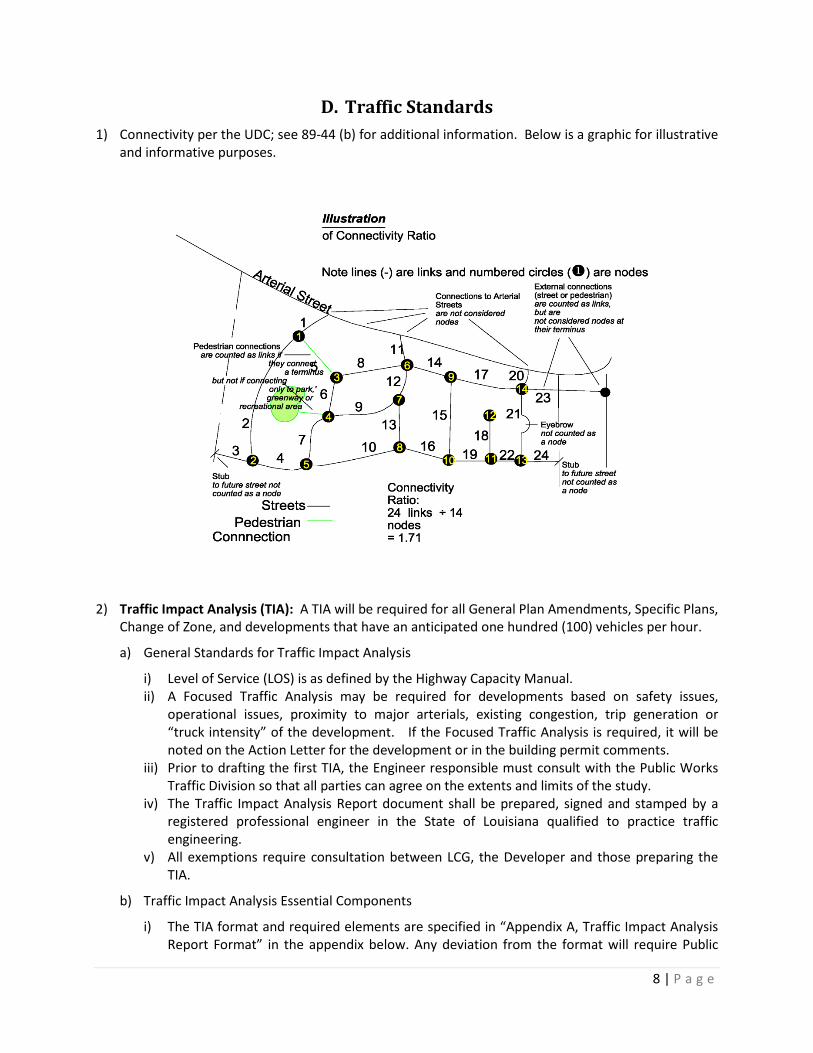
D. Traffic Standards 1) Connectivity per the UDC; see 89-44 (b) for additional information. Below is a graphic for illustrative
and informative purposes.
2) Traffic Impact Analysis (TIA): A TIA will be required for all General Plan Amendments, Specific Plans,
Change of Zone, and developments that have an anticipated one hundred (100) vehicles per hour.
a) General Standards for Traffic Impact Analysis
i) Level of Service (LOS) is as defined by the Highway Capacity Manual. ii) A Focused Traffic Analysis may be required for developments based on safety issues,
operational issues, proximity to major arterials, existing congestion, trip generation or “truck intensity” of the development. If the Focused Traffic Analysis is required, it will be noted on the Action Letter for the development or in the building permit comments.
iii) Prior to drafting the first TIA, the Engineer responsible must consult with the Public Works Traffic Division so that all parties can agree on the extents and limits of the study.
iv) The Traffic Impact Analysis Report document shall be prepared, signed and stamped by a registered professional engineer in the State of Louisiana qualified to practice traffic engineering.
v) All exemptions require consultation between LCG, the Developer and those preparing the TIA.
b) Traffic Impact Analysis Essential Components
i) The TIA format and required elements are specified in “Appendix A, Traffic Impact Analysis Report Format” in the appendix below. Any deviation from the format will require Public
9 | P a g e
Work’s (Traffic) approval prior to submission. At a minimum, the TIA document shall include the following major components:
(1) Study Area which includes: (1) Site access driveways (existing and proposed) (2) Roadways adjacent to the project site. (3) Intersections in the immediate vicinity of the project site. (4) Any intersection of a collector or higher classification street with a collector or
higher classification street to which the proposed project will add 50 or more peak hour trips.
(5) Roadway links between study intersections and/or project driveways when required.
(2) The circulation system Level of Service determination required by the Unified Development Code (UDC) and the following scenarios: (1) Existing Traffic Conditions – Existing traffic volumes will be analyzed to determine
current conditions. Traffic count data shall be new or recent. In some cases, data up to one year old may be accepted, upon approval by Public Works. The TIA shall identify any existing Level of Service deficiencies.
(2) Existing Traffic Conditions (with Project) – Project generated traffic shall be added to the existing traffic count data. The TIA shall identify and analyze impacts to the existing circulation system. This analysis will be used to determine direct project impacts to the existing circulation system.
(3) Opening Year Traffic Conditions (without Project) – Traffic Conditions will be projected to the estimated project opening by increasing traffic volumes by an appropriate growth rate to be provided by Public Works staff. The TIA shall identify any LOS deficiencies.
(4) Opening Year Traffic Conditions (with Project) – Project generated traffic shall be added to the Opening Year data. The TIA shall identify and analyze impacts to the circulation system. This will be the basis for determining project specific impacts, mitigation, and conditions of approval.
(5) Cumulative Traffic Conditions – Traffic generated by other approved projects within a one mile radius of the project site that will affect the study area shall be identified and added to the Opening Year traffic identified in Scenario D; this includes proposed projects that are in review process, but not yet approved.
(6) Project Phasing – Traffic conditions at each project phase completion shall be analyzed using the same approach as Opening Year (with and without project), if applicable. Traffic associated with each project phase shall be included in the analyses of each successive phase of the proposed project.
(7) General Plan Traffic Conditions – Traffic projections for General Plan Build Out conditions shall utilize the LCG traffic model or other approved model. The Engineer shall use the model projections as the basis for determining turning movement volumes for the required intersection analysis. A manual assignment of project traffic added to the General Plan Build Out traffic volumes may be used to determine total future traffic. This analysis will determine if the Circulation Element of the General Plan is adequate to accommodate projected traffic at the target LOS, or if additional mitigation is necessary.
(3) Mitigation measures to maintain the required Level of Service

10 | P a g e
(1) At intersections where the LOS falls below or is expected to fall below an acceptable threshold with the addition of project traffic, feasible measures shall be identified to mitigate the project’s impacts for the following conditions: (a) Existing Conditions (with Project) (b) Opening Year Traffic Conditions (with Project) (c) Cumulative Traffic Conditions (with Project) (d) General Plan Traffic Conditions.
(2) In all cases, the feasibility of the proposed improvements must be demonstrated and the necessary improvements and Right-of-Way must be dedicated, if needed.
(4) Feasibility of mitigation measures (5) Coordination with DOTD for projects within 0.25 miles of a state highway or a project
that will impact the function of a state highway
c) Additional Analysis Components which may be needed according to the Study Area or Project Details include: i) Truck Intensive
(1) Truck access routes (2) Adequacy of streets to be used (geometry and structural section) (3) Safety issues relating to the truck traffic (4) Traffic signal operation and queueing (5) Potential impacts of truck traffic on existing residences or businesses (6) Application of a Passenger Car Equivalent (PCE) factor to the project trips may be
required but these must be approved by Public Works prior to the analysis
ii) Special event facilities (such as sports stadiums, racetracks, water parks, etc.): (1) Weekend and off-peak scenarios (2) A traffic management plan to mitigate traffic impacts associated with an event (3) Adequate area wide access
d) Level of Service (LOS) Analysis Methodology
i) LCG’s UDC has established minimum LOS standard for LCG’s Arterial Highway network. The TIA shall determine if the required LOS can be achieved after the construction of the proposed project. The TIA shall include all LOS calculations for affected study area intersections and roadway links. All LOS calculations shall be performed utilizing the Synchro Software Program or approved equal. The result of the “with-project” conditions shall conform to LCG’s LOS thresholds shown below: (1) LOS “D” or better at all intersections (2) LOS “E” or better for all arterial highway segments (links) (3) LOS “F” or better will be permitted in special occasions
ii) All study area intersections or study area roadway links that do not achieve the required LOS, shall be reanalyzed using the proposed mitigation measures to determine if the required LOS can be achieved.
iii) If added project traffic causes an increase in delay of four (4) seconds or more at intersections operating at LOS “E” or “F”, it shall be considered a significant impact and mitigation measures will be required to reduce the delay to pre-project or acceptable conditions.
11 | P a g e
iv) Proposed projects with heavy truck usage shall apply Passenger Car Equivalent (PCE) factors to determine intersection delays. The PCE factors shall be approved by LCG prior to the analysis.
v) Link Analysis (1) When required, a roadway link analysis shall be performed using the methodology in
the Transportation Research Board’s Highway Capacity Manual latest edition. (2) LOS “E” or better shall be maintained at all study area intersections.
vi) Intersection Analysis (1) An intersection level of service analysis shall be performed using the methodology in the
latest edition of the Transportation Research Board’s Highway Capacity Manual. (2) LOS “D” or better shall be maintained at all study area intersections. (3) Intersection analyses shall be performed using the latest version of the Synchro
software (or approved equal). Closely spaced intersections shall be evaluated based on the 85th percentile queue length to ensure that turn lane storage and queue lengths do not exceed the available turn pocket length.
(4) Where applicable, a roundabout analysis shall be performed using SIDRA (or approved equal software). The roundabout analysis worksheets shall be included in the TIA document’s appendices.
(5) Traffic Signal Warrant Analysis (1) The traffic signal warrant analysis shall be performed using the latest edition of the
Manual on Uniform Traffic Control Devices (MUTCD). The warrant analysis worksheets shall be included in the TIA document’s appendices.
(2) Actual traffic signal timing to peak hour factors for intersections shall be collected in the field and utilized for the existing and near-term analyses. In cases where traffic is added from a significant number of cumulative projects, the consultant shall use their engineering judgment in the application of peak hour factors to maintain consistency with the existing conditions analyses. A peak hour factor of 1.0 shall be
applied to Build Out traffic conditions.
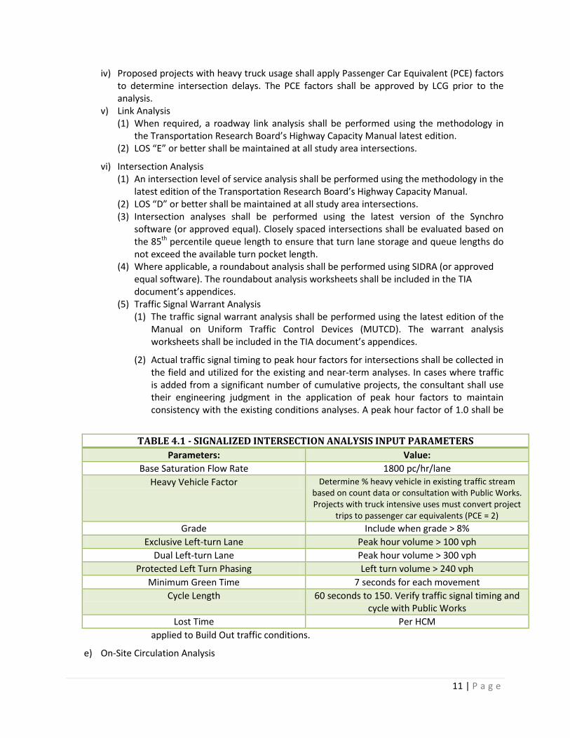
e) On-Site Circulation Analysis
TABLE 4.1 - SIGNALIZED INTERSECTION ANALYSIS INPUT PARAMETERS Parameters: Value:
Base Saturation Flow Rate 1800 pc/hr/lane Heavy Vehicle Factor Determine % heavy vehicle in existing traffic stream
based on count data or consultation with Public Works. Projects with truck intensive uses must convert project
trips to passenger car equivalents (PCE = 2) Grade Include when grade > 8%
Exclusive Left-turn Lane Peak hour volume > 100 vph Dual Left-turn Lane Peak hour volume > 300 vph
Protected Left Turn Phasing Left turn volume > 240 vph Minimum Green Time 7 seconds for each movement
Cycle Length 60 seconds to 150. Verify traffic signal timing and cycle with Public Works
Lost Time Per HCM
12 | P a g e
i) The TIA shall evaluate the proposed on-site circulation for the project and address the adequacy of the proposed circulation. This includes identifying the traffic control at project driveways and/or intersections.
f) Safety and Operational Improvements Analysis
i) The TIA shall evaluate the existing roadway conditions to determine if safety and/or operational improvements are necessary due to increase in traffic from the project or cumulative projects. The types of improvements needed may include, but are not limited to: (1) Additional through and/or turn lanes, including free right turn lanes (2) Increase left and/or right turn lane length (3) Parking restriction (4) Measures to reduce cut-through project traffic in adjacent residential areas (5) Queue lengths and impacts to adjacent intersections (6) Need for traffic signal coordination (7) Bicycle facilities
3) Parking Lot Standards
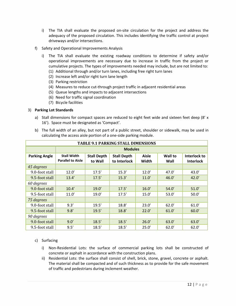
a) Stall dimensions for compact spaces are reduced to eight feet wide and sixteen feet deep (8’ x 16’). Space must be designated as ‘Compact’.
b) The full width of an alley, but not part of a public street, shoulder or sidewalk, may be used in calculating the access aisle portion of a one-side parking module.
TABLE 9.1 PARKING STALL DIMENSIONS Modules
Parking Angle Stall Width Parallel to Aisle
Stall Depth to Wall
Stall Depth to Interlock
Aisle Width
Wall to Wall
Interlock to Interlock
45 degrees 9.0-foot stall 12.0’ 17.5’ 15.3’ 12.0’ 47.0’ 43.0’ 9.5-foot stall 13.4’ 17.5’ 15.3’ 11.0’ 46.0’ 42.0’
60 degrees 9.0-foot stall 10.4’ 19.0’ 17.5’ 16.0’ 54.0’ 51.0’ 9.5-foot stall 11.0’ 19.0’ 17.5’ 15.0’ 53.0’ 50.0’
75 degrees 9.0-foot stall 9.3’ 19.5’ 18.8’ 23.0’ 62.0’ 61.0’ 9.5-foot stall 9.8’ 19.5’ 18.8’ 22.0’ 61.0’ 60.0’
90 degrees 9.0-foot stall 9.0’ 18.5’ 18.5’ 26.0’ 63.0’ 63.0’ 9.5-foot stall 9.5’ 18.5’ 18.5’ 25.0’ 62.0’ 62.0’
c) Surfacing
i) Non-Residential Lots: the surface of commercial parking lots shall be constructed of concrete or asphalt in accordance with the construction plans.
ii) Residential Lots: the surface shall consist of shell, brick, stone, gravel, concrete or asphalt. The material shall be compacted and of such thickness as to provide for the safe movement of traffic and pedestrians during inclement weather.
13 | P a g e
d) Drainage
i) Parking lots shall have on-site drainage such that surface rainwater will not be allowed to flow across any sidewalks or properties of different ownership adjoining the property proposed for off-street parking.
ii) The size and positioning of culverts and drains shall be approved by Public Works.
e) Wheel guards
i) Wheel guards or bumper guards must be placed so that no part of parked vehicles will be able to extend beyond the parking facility.
ii) The distance from the property line to the wheel guard shall be a minimum of three feet (3’).
4) Traffic Calming
a) Traffic concerns and issues related to speeding and traffic volumes can often be anticipated and prevented through street design and the addition of traffic calming. Traffic calming measures for new developments will provide a neighborhood street network that discourages excessive vehicle speeds and manages congestion.
b) Traffic calming tools/devices available
i) Neighborhood traffic circles or mini roundabouts ii) Raised intersections iii) Midblock raised median island iv) Curb extension or bulb outs v) Bicycle lanes vi) Corner radii less than 25’ vii) Speed humps or lumps
c) Traffic calming devices should be considered in proposed subdivisions with thirty (30) or more lots. Installation is encouraged along uninterrupted straight street sections of eight hundred feet (800’) or greater. Traffic calming devices with approximate five-hundred foot (500’) spacing generally maintain eighty-fifth (85th) percentile speeds of twenty-five (25) mph. The street network may be designed to maintain a certain design speed (typically twenty-five (25) mph in residential areas) by utilizing proper lane width, curve geometry, sidewalk location and design, as well as placement of traffic calming devices.
5) Requests for Lane/Road Closures
a) Lane/road closures on state highways cannot be permitted by LCG; contact LADOTD at (337) 262-6121 for more information
b) Contact LCG/Traffic Engineering and Development at (337) 291-8531 if the road is located within the incorporated areas of the City of Lafayette or the unincorporated areas of Lafayette Parish.
c) Construction Related Closures – not related to emergency repairs
i) Lane closures must be made 48-72 hours in advance. ii) Road closures must be made 72 hours in advance.
d) Non-Construction Related Closures (i.e. block parties)- Because this permit requires approval from Fire, Police and Public Works Director it must be made fourteen days in advance
14 | P a g e
E. Roadway Standards 1) Roadway Standards (Minimums)
a) All Roads Design Standards/Requirements
i) Pavement section shall be determined by an analysis of the in-situ soils or borrow material and certified by the Design Engineer as adequate for future traffic loading with a twenty (20) year design life. The minimum pavement section shall be three inches (3”) wearing surface on eleven inch (11”) soil cement base or eight inches (8”) concrete pavement on six inch (6”) limestone base.
ii) The center line grade of all streets is subject to approval by Public Works. iii) When a roadway is elevated above natural ground, the fill area shall not exceed two feet (2’)
above natural ground unless specifically approved in writing by the Department of Public Works.
iv) When an asphalt road intersects with a concrete road, the turnout for the asphalt road shall match the section of the concrete road in materials and thicknesses.
v) Roundabouts shall be constructed with concrete pavement through the aprons. vi) When a proposed roadway intersects a street that has insufficient lane width, speed limit of
30 miles per hour or greater, average daily traffic greater than 5,000 vehicles per day, or as directed by the City Engineer; the intersecting road’s radii shall be at least thirty (30’) feet.
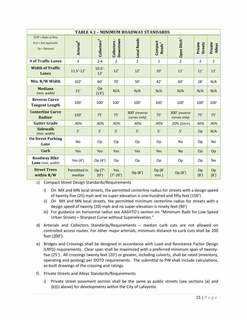
b) The actual right-of-way for all roadways varies based on the number of travel lanes, lane widths, and the provision of other elements to support the type and density of adjoining land uses including parallel or angled on-street parking, buffer planting zones with landscapes and streetscape materials, pedestrian zones and sidewalk widths, on-street bike facilities, medians, and toe of slope (i.e. minimum 4:1 (H:V)) required fill material. The minimum requirements are in the table:
15 | P a g e
TABLE 4.1 – MINIMUM ROADWAY STANDARDS R/W = Right-of-Way
N/A = Not Applicable
Op = Optional
Arte
riald
Colle
ctor
sd
Colle
ctor
s -
Dow
ntow
n
Loca
l Roa
ds
Com
pact
Ro
ads c
Ope
n Di
tch j
Priv
ate
Stre
ets
Priv
ate
Alle
ys
# of Traffic Lanes 4 2-4 2 2 2 2 2 2
Width of Traffic Lanes 11.5’-12’ 10.5’-
12’ 12’ 12’ 10’ 11’ 11’ 11’
Min. R/W Width 102’ 60’ 70’ 50’ 42’ 60’ 28’ N/A
Medians (min. width) 21’ Op
(13’) N/A N/A N/A N/A N/A N/A
Reverse Curve Tangent Length 100’ 100’ 100’ 100’ 100’ 100’ 100’ 100’
Centerline Curve Radiusc 150’ 75’ 75’ 300’ (reverse
curves only) 75’ 300’ (reverse curves only) 75’ 75’
Gutter Grade .40% .40% .40% .40% .40% .20% (Ditch) .40% .40% Sidewalk (min. width) 5’ 5’ 5’ 5’ 5’ 5’ Op N/A
On Street Parking Lane No Op Op Op Op No Op No
Curb Yes Yes Yes Yes Yes No Op Op
Roadway Bike Lane (min. width) Yes (4’) Op (4’) Op Op Op Op Op No
Street Trees within R/W
Permitted in median
Op (7’-20’)
Yes (7’-20’) Op (8’) Op (8’
min.) Op (8’) Op (8’)
Op (8’)
c) Compact Street Design Standards/Requirements
i) On MX and MN local streets, the permitted centerline radius for streets with a design speed of twenty-five (25) mph and no super-elevation is one-hundred and fifty feet (150’)
ii) On MX and MN local streets, the permitted minimum centerline radius for streets with a design speed of twenty (20) mph and no super-elevation is ninety feet (90’)
iii) For guidance on horizontal radius see AASHTO’s section on “Minimum Radii for Low Speed Urban Streets – Sharpest Curve without Superelevation.”
d) Arterials and Collectors Standards/Requirements – median curb cuts are not allowed on controlled access routes. For other major arterials, minimum distance to curb cuts shall be 200 feet (200’).
e) Bridges and Crossings shall be designed in accordance with Load and Resistance Factor Design (LRFD) requirements. Clear span shall be maximized with a preferred minimum span of twenty-five (25’). All crossings twenty feet (20’) or greater, including culverts, shall be rated (inventory, operating and posting) per DOTD requirements. The submittal to PW shall include calculations, as-built drawings of the crossing and ratings.
f) Private Streets and Alleys Standards/Requirements
i) Private street pavement section shall be the same as public streets (see sections (a) and (b)(i) above) for developments within the City of Lafayette.
16 | P a g e
ii) For developments within the Unincorporated Parish of Lafayette, the following private street construction requirements apply: (1) Subdivisions on existing private roads, private rights-of-passage or other private access
agreements are to submit sufficient topographic information and existing cross section to insure stable passage and adequate drainage.
(2) Subdivisions will fifteen (15) lots or fewer shall meet the requirements of 89-44 (d) j which includes either four (4) inches of aggregate or two (2) inches of asphalt placed over a base of either ten (10) percent lime treated soil ten (10) inches thick or eight (8) inches of soil cement and the turnout for the private road shall match the section of the concrete road in materials and thicknesses, if the adjoining public street is a concrete roadway.
(3) Subdivisions will more than fifteen (15) lots shall meet the requirements of sections (a) and (b)(i) above.
iii) Intersections of all private streets and private alleys with public streets must be constructed with right angles, the variations of which are not to exceed ten (10) degrees. Pavement at these intersections shall have twenty-five foot (25’) radii at all corners.
iv) Parallel parking is not allowed along a private alley. Therefore, the owner of the alley must, at his expense, conspicuously display signs prohibiting parallel parking.
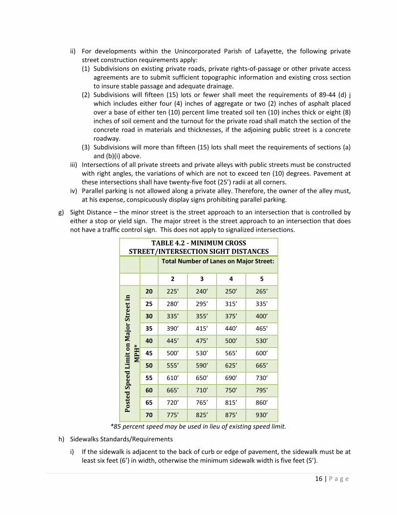
g) Sight Distance – the minor street is the street approach to an intersection that is controlled by either a stop or yield sign. The major street is the street approach to an intersection that does not have a traffic control sign. This does not apply to signalized intersections.
TABLE 4.2 - MINIMUM CROSS STREET/INTERSECTION SIGHT DISTANCES
Total Number of Lanes on Major Street:
2 3 4 5
Post
ed S
peed
Lim
it o
n M
ajor
Str
eet i
n M
PH*
20 225’ 240’ 250’ 265’
25 280’ 295’ 315’ 335’
30 335’ 355’ 375’ 400’
35 390’ 415’ 440’ 465’
40 445’ 475’ 500’ 530’
45 500’ 530’ 565’ 600’
50 555’ 590’ 625’ 665’
55 610’ 650’ 690’ 730’
60 665’ 710’ 750’ 795’
65 720’ 765’ 815’ 860’
70 775’ 825’ 875’ 930’
*85 percent speed may be used in lieu of existing speed limit.
h) Sidewalks Standards/Requirements
i) If the sidewalk is adjacent to the back of curb or edge of pavement, the sidewalk must be at least six feet (6’) in width, otherwise the minimum sidewalk width is five feet (5’).
17 | P a g e
ii) Sidewalks shall avoid obstacles such as ditches, trees, and utilities. iii) Sidewalks shall be at least four inches (4”) thick of 2500 psi Portland cement concrete.
Sidewalks across driveways, and other sidewalks that will be crossed by vehicles, will be at least six inches (6”) thick for residential drives or at least eight inches (8”) thick for commercial drives or, where applicable, as thick as the driveway, whichever is greater.
iv) Sidewalk joints are to be spaced at intervals matching sidewalk width with expansion joints spaced every sixty (60’) feet. Expansion joints are also required on either side of a driveway.
v) The sidewalk will be continuous over the full frontage of the development. Lots located where a public street lies adjacent to the lot on more than one side (i.e. corner lots, etc.) are not exceptions to this requirement. Neither the developer nor the property owner will be allowed to construct permanent or temporary structures (i.e. fences, etc.) within the designated sidewalk servitude on one or more sides of such lots. Failure to comply will result in the removal of the structure at the expense of the developer or owner.
vi) At street corners, the sidewalk in both directions will extend to the pavement edge. If a ditch culvert is required to accomplish this, it will be considered part of the sidewalk requirement. The size and grade of culverts will be determined by the Development Engineer and approved by the Department of Public Works.
vii) The developer shall construct handicap ramps and markings as required by federal law. The preferred color for handicap ramps at roadways is Vermilion Red or Safety Yellow.
i) Bikeways Standards/Requirements: Bikeways that are separate from the roadway shall have a minimum width of seven feet (7’) and shall be constructed of Portland cement concrete.
j) Street Lighting Standards/Requirements: See LUS’s Standards for details. Any public street light relocation needed for improvements is the responsibility of the developer. The developer is required to submit a street lighting analysis performed by a licensed professional engineer in the State of Louisiana to certify that the minimum average maintained horizontal illumination, as set forth in the Illuminating Engineering Society of North American (IES) publication number RP-8, (Americana National Standard Practice for Roadway Lighting) latest edition, are met for any street light(s) required to be relocated. Additional street light standards, pending review/approval of the above street lighting analysis, may be necessary to meet IES requirements.
k) Open Ditch Provisions (where open ditches have been permitted by Public Works)
i) Rights-of-way exceeding sixty feet (60’) may be required depending on the depth and cross section of roadside ditches and an evaluation of the developer’s drainage design.
ii) Right-of-way width shall be determined by pavement width, maximum ditch side slopes 3:1 (H:V) for foreslope, and 2:1 (H:V) for backslope, and a with a minimum shoulder width of five feet (5’) unless otherwise approved by Public Works.
iii) Ditches shall be planted with suitable ground cover to control erosion. iv) No objects or culverts shall be placed within the drainage system without prior written
approval from Public Works. v) For development with open ditch systems, the Development Engineer shall include a culvert
sizing chart for each future driveway location based on the design storm flows, depth of cover and constructability.
2) Drainage System Standards
a) The minimum size pipes for any culvert shall be fifteen inch (15”) diameter. The design life of the materials used for a drainage system shall be a minimum of fifty (50) years.
18 | P a g e
i) All roadway cross drains shall be reinforced concrete; no other material (i.e. plastic, metal, etc.) will be accepted unless otherwise approved by Public Works.
ii) Aluminum culverts may be used only for outfall termini at channels or as otherwise approved by the Public Works. The predicted design service life for metal culverts shall be determined by calculating the net effect of corrosion from both interior and exterior conditions concurrently.
iii) Buoyancy calculations shall be performed on all runs of pipe that do not utilize concrete pipe. Buoyancy calculations shall be prepared, signed, and sealed by a registered engineer, shall represent actual field conditions, and shall demonstrate that the pipe utilized will not become buoyant under any condition.
iv) Pipe joints shall be wrapped with an approved filter fabric and banded on each end with a non-corroding plastic strap secured by self-sealing buckles.
v) Lateral drainage systems from the street to an outfall channel which traverse lots shall be provided by a subsurface pipe drain with a minimum twenty (20’) foot permanent drainage servitude. Actual width of drainage servitude required will be determined by Public Works based upon outside pipe diameter, depth of pipe, the 2:1 (H:V) excavation side slope, and maintenance equipment limitations.
b) Drainage structures shall be designed such that the pipe does not enter at the corners of the structure. A minimum of six inches (6”) or the thickness of the structure wall, whichever is greater, is required at each corner from the edge of the structure to the outside wall of the pipe.
c) Any construction/excavation adjacent to a natural water course, coulee, ditch, or other drainage facility shall include appropriate erosion protection along the full length of the water course within the confines of the property being developed.
d) Any development outfall that is within the wall section of a concrete lined coulee shall be structurally designed and the entire wall panel evaluated for integrity.
e) Embankment slopes of coulees and drainage ditches shall have slopes which are not in excess of 2:1 (H:V), unless supported by geotechnical slope stability analysis, and shall have appropriate erosion control as approved by Public Works. End of pipe treatments shall be for both the upstream and downstream ends of pipe. Utilization of articulated block matting may be required. Slope requirements around pipe terminus shall be the same as side slope of channel. Side slopes shall be protected.
f) Emergency spillways shall be in an area that will least affect traffic flow and not cause flooding of structures intended for occupancy.
g) Features that ease maintenance problems and reduce maintenance costs shall be included in the design of the storm water management facility (retention/detention pond ) to the greatest extent practicable; such features include:
i) A forebay to capture a greater part of incoming sediments ii) A reinforced maintenance platform alongside the forebay to facilitate sediment removal iii) Ponds greater than five (5) acres in surface area should include a device to temporarily
lower the elevation of the permanent pool iv) Incoming flow diversion alongside the maintenance platform to facilitate sedimentation
along the maintenance platform rather than in the middle of the facility
19 | P a g e
h) If a developer and/or homeowner establishes a private drainage servitude across lot lines, then the drainage facility cannot utilize open ditches but is restricted to sub-surface drainage the entire length of the servitude.
i) Any private drainage servitude that benefits a lot within a development shall be included on the final plat of the development or copies of the recorded documents shall be provided to Public Works prior to issuance of certificates of occupancy.
j) Private drainage facilities shall be maintained per UDC 89-42 (f). In no event shall LCG be obligated to perform desiltation on private retention/detention facilities if LCG determines the owner of the facility has not properly maintained the facility.
3) Driveway Standards (Driveway Permit)
a) All driveways are required to be permitted either through the driveway permit application or building permit application. Driveways installed due to an LCG project will be reviewed during the design review. No objects or culverts shall be placed within the drainage system without prior written approval from Public Works.
b) Along open ditch roads, a maximum of thirty-two feet (32’) of culverts for a driveway crossing or up to fifty-six feet (56’) for circle and horseshoe driveways is allowed, unless safety conditions warrant additional pipe installation.
c) All proposed sub-surfacing of an open ditch drainage system exceeding thirty-two feet (32’) shall be supported by a hydraulic analysis prepared by a Louisiana Registered Professional Engineer.
d) Under no circumstance shall the slope of the fill for any driveway along open ditch roads be less than 3:1 (H:V) measured from the surface of the driveway to the top of the pipe at the end of the pipe.
e) The grades of a driveway and sidewalk shall be mutually compatible to provide an uninterrupted sidewalk grade for safe pedestrian movement and in accordance with the Americans with Disabilities Act (ADA) and other applicable federal regulations.
f) Maximum slope of a driveway within the right-of-way is 1:10.
g) The driveway within the right-of-way shall be constructed of the same or more durable material as the adjoining street.
h) Mountable curb along commercial developments is only permitted at the driveway.
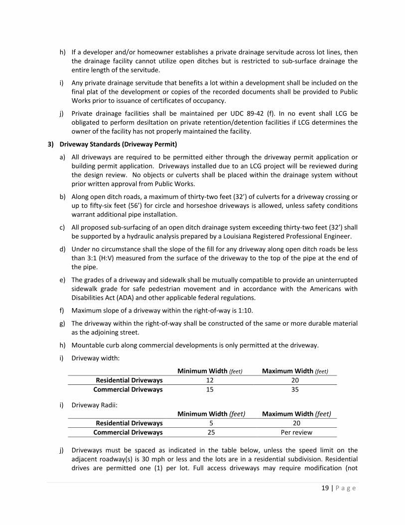
i) Driveway width:
Minimum Width (feet) Maximum Width (feet) Residential Driveways 12 20
Commercial Driveways 15 35
i) Driveway Radii: Minimum Width (feet) Maximum Width (feet)
Residential Driveways 5 20 Commercial Driveways 25 Per review
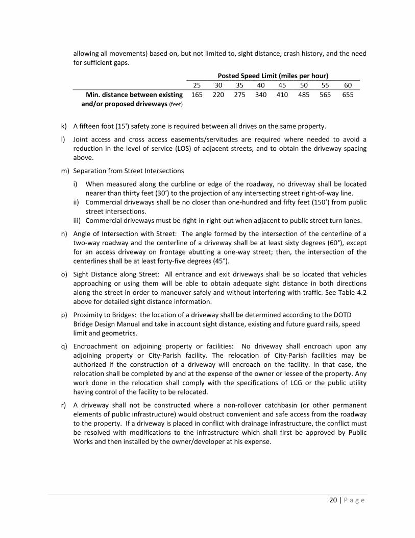
j) Driveways must be spaced as indicated in the table below, unless the speed limit on the
adjacent roadway(s) is 30 mph or less and the lots are in a residential subdivision. Residential drives are permitted one (1) per lot. Full access driveways may require modification (not
20 | P a g e
allowing all movements) based on, but not limited to, sight distance, crash history, and the need for sufficient gaps.
Posted Speed Limit (miles per hour) 25 30 35 40 45 50 55 60
Min. distance between existing and/or proposed driveways (feet)
165 220 275 340 410 485 565 655
k) A fifteen foot (15') safety zone is required between all drives on the same property.
l) Joint access and cross access easements/servitudes are required where needed to avoid a reduction in the level of service (LOS) of adjacent streets, and to obtain the driveway spacing above.
m) Separation from Street Intersections
i) When measured along the curbline or edge of the roadway, no driveway shall be located nearer than thirty feet (30’) to the projection of any intersecting street right-of-way line.
ii) Commercial driveways shall be no closer than one-hundred and fifty feet (150’) from public street intersections.
iii) Commercial driveways must be right-in-right-out when adjacent to public street turn lanes.
n) Angle of Intersection with Street: The angle formed by the intersection of the centerline of a two-way roadway and the centerline of a driveway shall be at least sixty degrees (60°), except for an access driveway on frontage abutting a one-way street; then, the intersection of the centerlines shall be at least forty-five degrees (45°).
o) Sight Distance along Street: All entrance and exit driveways shall be so located that vehicles approaching or using them will be able to obtain adequate sight distance in both directions along the street in order to maneuver safely and without interfering with traffic. See Table 4.2 above for detailed sight distance information.
p) Proximity to Bridges: the location of a driveway shall be determined according to the DOTD Bridge Design Manual and take in account sight distance, existing and future guard rails, speed limit and geometrics.
q) Encroachment on adjoining property or facilities: No driveway shall encroach upon any adjoining property or City-Parish facility. The relocation of City-Parish facilities may be authorized if the construction of a driveway will encroach on the facility. In that case, the relocation shall be completed by and at the expense of the owner or lessee of the property. Any work done in the relocation shall comply with the specifications of LCG or the public utility having control of the facility to be relocated.
r) A driveway shall not be constructed where a non-rollover catchbasin (or other permanent elements of public infrastructure) would obstruct convenient and safe access from the roadway to the property. If a driveway is placed in conflict with drainage infrastructure, the conflict must be resolved with modifications to the infrastructure which shall first be approved by Public Works and then installed by the owner/developer at his expense.
21 | P a g e
III. Submittal Requirements 1) Construction Plans: the Design Engineer shall submit the development drainage construction plans,
either plan-profile sheets or grading and drainage sheets, detailing the following information:
a) The location, description, and elevation of permanent or temporary benchmarks to be used in the construction of the improvements, shall be shown on the plans. All elevations shall be NAVD 88 measured to at least second order accuracy or better.
b) A note shall be made on the drainage plan sheet if any portion of the development, lot, or street is within the 100-year floodplain.
c) Existing topographic plan with elevations and grading plan with elevations
d) A sufficient number of grading sections (as required by Public Works) to adequately evaluate site drainage patterns
e) Drainage pipe materials
f) If open ditch has been permitted, culvert sizes for road crossings and for driveways, and documentation of the flow rate
g) Profile of outlet structure connecting to existing outfall which must also depict utility crossings and identify all conflicts
h) Details of retention/detention facility: typical sections and stage/storage information of the detention facility (for acceptable facilities see Subsection II.5 above)
i) Detail of construction access entrance ii) Detail of construction silt fencing and erosion control plan. These items shall be in place
prior to construction of the form work for the building improvements and/or site improvements. (See Section 34-401 through 34-570 Stormwater Management)
i) If a detention facility is within a parking lot, then parking lot grades, curb grades, areas identifying ponding limits and depths must be submitted.
j) The cubic feet per second (cfs) of storm water resulting at each development entry point from a designated storm. This determination shall be based on the existing land use of the upstream drainage areas.
k) All other applicable forms, tables, charts, etc.
l) LCG projects will also meet the requirements of the project’s design contract.
2) Drainage Impact Study: shall be submitted in a “bound” booklet form and consist of three (3) distinct and designated parts as follows:
a) Summary: the effect of the proposed construction on upstream and downstream areas
b) Design Criteria: a detailed explanation and description of the methodology, data and assumptions used with separation between the pre-development and post-development criteria; it must specifically include:
i) An area drainage map for the existing and design areas which identifies: (1) The various drainage areas involved/affected in the existing conditions and proposed
conditions including an existing drainage area map (Minimum of two (2) grading sections of entire site (i.e., one (1) east/west and one (1) north/south) and design
22 | P a g e
drainage area map (Minimum of two (2) grading sections of entire site (i.e., one (1) east/west and one (1) north/south)
(2) The acreage in each drainage area (3) The slope of each drainage area to the entry point and/or exit point of the development
ii) typical sections, cross sections, stage/storage information and such other details as required by the review engineer for review of the proposed development
c) Calculations: clear, concise, step-by-step calculations performed to support the drainage system design with separation between the pre-development and post-development calculations; it must specifically include:
i) Inflow/outflow results (highlighted for ease of identification during review) ii) The cubic feet per second (cfs) of storm water at each development exit point resulting from
a design storm. This determination shall be based on the existing land use of the upstream drainage areas whether inside or outside the development; This calculation shall take into account expected construction within the development that will change the grades, direction of flow, run-off factors or other existing conditions.
iii) The maximum peak flow, expressed in cubic feet per second, of existing and proposed drainage structures within the development based on the design storm event.
iv) Parking lot grades, curb grades, areas identifying ponding limits and depths if detention facility is within a parking lot
v) All hydrographs and routing curves vi) All other applicable forms, tables, charts, etc. vii) Detailed explanation of pre-development analysis, post-development analysis, routing
conclusion, and engineer’s evaluation of whether the development has satisfied all of the hydraulic requirements
3) Street Sign Installation: Appropriate street signs shall be in accordance with the Manual on Uniform Traffic Control Devices (MUTCD) and will be required on all public and private streets.
a) The request for street signage shall be made by the Developer after the roadways are constructed and prior to recording the Final Plat. The request shall be made to Travis Smith ([email protected]) with copy to Sara Gary ([email protected]). The subject line of the request shall include the PC or HE reference number as well as the name of the plat.
b) Street signs on all public streets shall be installed by LCG with all labor and materials billed to the Developer by PZD. Street signs on private streets intersecting a public street shall follow this process as well.
c) Installation of permanent street signs at intersections of private streets with other private streets or along private streets shall be the sole responsibility of the Developer. The maintenance of those signs will become the responsibility of the owner of the private street. Private street signs shall follow the attached details found in Appendix C.
4) Inspection Reports: Reports are to include day, date, weather conditions, equipment on site and being used, number of contractor employees on site, description of work being performed, number of hours inspector was on-site.
5) Pipe Video: all public subsurface drainage systems shall be videoed for deficiencies, missing plugs, joint construction, sediment and any other issues by the owner/developer for review and recommendation by the design engineer and acceptance by PW.
23 | P a g e
IV. Waivers 1) Waivers for Drainage Impact Study
a) All waivers shall be supported by a hydraulic analysis (prepared by the developer’s engineer) concluding that the existing system has the capacity to accept the increase of discharge rate.
b) A waiver will be considered in areas where existing and/or development conditions will not accommodate equivalent discharge rates, as determined solely by Public Works, a maximum five percent (5%) increase of the pre-development’s discharge rate, not to exceed five (5) cubic feet per second, may be allowed.
c) No retention/detention requirement shall be allowed for developments of three-fourths (3/4) of an acre or less. Runoff to the adjacent roadway, outfall or other properties for these sized developments shall not, however, be allowed as a single point discharge unless approved by the Public Works Director (or his/her designee). Rather, in these cases, a drainage site and grading plan shall be submitted for review and approval.
d) A waiver will be considered where a prior approved Drainage Impact Study was performed for the site, the analysis complies with the requirements of this Chapter, and conditions have not materially changed since the analysis was performed, or
e) A waiver will be considered where existing site conditions are such that a Drainage Impact Study would not provide information needed to determine whether the proposed development complies with this Section.
V. Certifications 1) The Engineer of Record responsible for design of the site plan, roadways, public infrastructure,
drainage plan, or detention facility for any development shall provide a letter of certification to Public Works prior to granting Final Plat approval or the Certificate of Occupancy for commercial building permits.
a) The letter shall certify that the improvements were constructed in accordance with the approved construction plans and specifications in addition to requirements stated in Section 89-59 Acceptance of Improvements for Perpetual Maintenance (e) and (f) of the UDC.
b) In addition to a general certification of the drainage design, the following elements of the design must be mentioned in the certificate, when applicable, as those which are being specifically certified by the engineer:
i) No more than seven inches (7”) pond flooding of parking lot(s) ii) Maximum thirty inch (30”) ditch depth iii) Construction Standards including roadway crossings have achieved minimum in-place
thicknesses and compaction iv) Construction was conducted in accordance with the approved Certificate of No Rise for work
within a designated floodway. v) The development was designed and constructed such that there is and will be no impact to
the adjacent properties or to the existing public infrastructure on which it relies. vi) Any deficient work noted in the installed drainage system video has been corrected and how
it was corrected.
24 | P a g e
c) The following work items warrant full time inspection of construction within public rights-of-way and drainage servitudes for LCG acceptance for perpetual maintenance. The inspector shall be certified in the appropriate work items by either LCG or DOTD: • Base work – including soil-cement, limestone, or prepared base • Surfacing – including asphalt and concrete. Inspection is not required during the application
of tack coats but verification of limits of application is required. • Curbing – placement and finish work • Drainage system – placement of drainage pipe, connection to drainage structures,
installation of structures, construction of open ditch system • Erosion protection – including grading of soil around drainage system, installation of
geotextile fabric • Utility installation – when utility work is within the public ROW, including open cuts of a
roadway or roadbed, jack and boring, directional boring. • Sidewalk installation – concrete placement. Inspector may have completed only the LCG
sponsored driveway ROW training for this construction activity. d) The following work items do not warrant full time inspection for LCG acceptance for perpetual
maintenance • Clearing and grubbing • Grading and preparation of roadway sub-base material • Grading and shaping of lots • Installation of private drainage systems • Construction of private roads, private alleys, and private drives not located within public
ROW • Hydroseeding, sodding, seeding, or other plantings

25 | P a g e
Appendix A
TRAFFIC IMPACT ANALYSIS REPORT FORMAT
The Traffic Impact Analysis Report shall consist of the following:
1. EXECUTIVE SUMMARY
A. Site Location and Study Area B. Project Description C. Findings
2. TABLE OF CONTENTS
A. List of Figures (Maps) B. List of Tables
3. INTRODUCTION
A. Purpose of the Traffic Impact Analysis and Objectives B. Site Location and Study Area (provide exhibit) C. Project Identification – Case Number and Related Case Numbers D. Project Description
• Project Size and Description • Existing Land Use and Zoning • Proposed Land Use and Zoning • Site Plan for Proposed Project (provide exhibit) • Proposed Project Opening Year • Proposed Phasing, if any • Indicate if proposed project is within an adjacent Area of Influence or adjacent to Parish
boundary
4. EXISTING TRAFFIC CONDITIONS
A. Identify Study Area and Intersections B. Existing Traffic Controls and Intersection Geometrics (provide exhibit)
• Description of Roadway System within the Study Area C. Existing Traffic Volumes
• AM/PM peak hour turning movement volumes and Roadway Average Daily Traffic (ADT) volumes (provide exhibit)
D. Existing Level of Service and Delay at Study Intersections (provide table) E. Existing Roadway Link Level of Service and Delay (provide table)
5. FUTURE TRAFFIC CONDITIONS
A. Project Opening Traffic • Project Trip Generation (provide table) – The latest edition of the Institute of
Transportation Engineers (ITE), Trip Generation shall be used. • Identify any factors used to adjust Project Trip Generation, such as pass-by trips and/or
internal trips. Adjusted rates shall be included in (provide table).
26 | P a g e
• Project Trip Distribution and Assignment (provide exhibit) • Project peak hour turning movement volumes and ADT (provide exhibit) • Existing Plus Project peak hour turning movement volumes (provide exhibit) • Ambient Growth Rate • Opening Year peak hour turning movement volumes without project (provide exhibit) • Total Opening Year peak hour turning movement volumes (provide exhibit) (Additional
Exhibits will be required for phased projects) B. Cumulative Traffic
• Ambient Growth rate • Identify location of other approved or proposed development projects (provide exhibit) • Trip Generation from other approved projects (provide table) • Trip Distribution and Assignment of other approved development projects (provide
exhibit) • Peak hour turning movement volumes without project (provide exhibit) • Total peak hour turning movement volumes with project (provide exhibit)
C. General Plan Traffic (When Required) • Identify Traffic Controls and intersection geometrics (provide exhibit) • Peak hour turning movement volumes without project (provide exhibit) • Total peak hour turning movement volumes with project (provide exhibit)
6. TRAFFIC ANALYSIS
A. Capacity and Level of Service (LOS) Analysis – Project Opening Traffic • Intersection LOS and Delay Existing Plus Project (provide table) • Intersection LOS and Delay Opening Year without project (provide table) • Intersection LOS and Delay Opening Year with project (provide table) • Roadway Link LOS with project (provide table) • Intersection LOS and Delay with improvements, if necessary to achieve LOS D (provide
table) B. Capacity and Level of Service (LOS) Analysis – Cumulative Traffic
• Intersection LOS and Delay without project (provide table) • Intersection LOS and Delay with project (provide table) • Roadway Link LOS with project (provide table) • Intersection LOS and Delay with improvements, if necessary to achieve LOS D (provide
table) C. Capacity and Level of Service (LOS) Analysis – General Plan Traffic
• Intersection LOS and Delay with project (provide table) • Roadway Link LOS with project (provide table) • Intersection and Roadway link LOS/Delay with improvements to achieve General Plan
LOS (provide table)
7. FINDINGS AND RECOMMENDATIONS
A. Proposed Mitigation Measures to Achieve LOS at Deficient Intersections for Existing, Opening Year, Cumulative, and General Plan Traffic Conditions (provide table)
B. Proposed Mitigation Measures to Achieve LOS at Deficient Roadway Links for Existing, Opening Year, Cumulative, and General Plan Traffic Conditions (provide table)

27 | P a g e
C. Traffic Signal Analysis
D. Recommended Improvements
• Intersection and Roadway Improvements • Traffic Control • On-Site Improvements • Parking Facility • Bicycle and Pedestrian Facility Improvements
E. Project Fair Share (provide table)
F. Conformance with Unified Development Code (UDC)
8. APPENDICES
A. Description of traffic data and how data was collected B. Description of methodologies and assumptions used in analyses C. Worksheets used in analyses (i.e. signal warrant, LOS etc.)
28 | P a g e
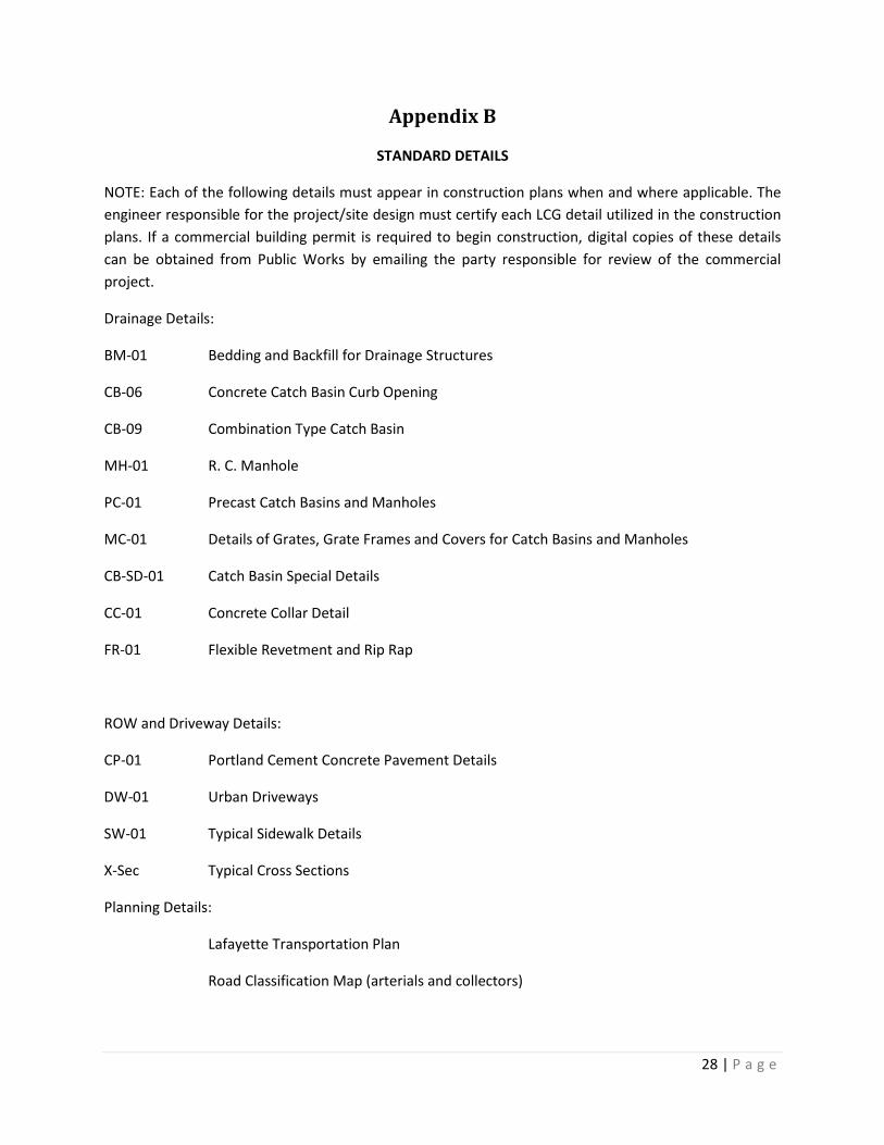
Appendix B
STANDARD DETAILS
NOTE: Each of the following details must appear in construction plans when and where applicable. The engineer responsible for the project/site design must certify each LCG detail utilized in the construction plans. If a commercial building permit is required to begin construction, digital copies of these details can be obtained from Public Works by emailing the party responsible for review of the commercial project.
Drainage Details:
BM-01 Bedding and Backfill for Drainage Structures
CB-06 Concrete Catch Basin Curb Opening
CB-09 Combination Type Catch Basin
MH-01 R. C. Manhole
PC-01 Precast Catch Basins and Manholes
MC-01 Details of Grates, Grate Frames and Covers for Catch Basins and Manholes
CB-SD-01 Catch Basin Special Details
CC-01 Concrete Collar Detail
FR-01 Flexible Revetment and Rip Rap
ROW and Driveway Details:
CP-01 Portland Cement Concrete Pavement Details
DW-01 Urban Driveways
SW-01 Typical Sidewalk Details
X-Sec Typical Cross Sections
Planning Details:
Lafayette Transportation Plan
Road Classification Map (arterials and collectors)

29 | P a g e
Appendix C Standards for Private Street Signs
Appropriate street signs in accordance with the Manual on Uniform Control Devices (MUTCD) will be required on all public and private streets
The request for street signage shall be made by the Developer after the roadways are constructed prior to recording the final plat. The request shall be made to Travis Smith ([email protected]) with copy to Sara Gary ([email protected]). The subject line of the request shall include the Planning Commission PC or Hearing Examiner HE reference number as well as the name of the plat.
Street signs on all public streets shall be installed by the Lafayette Consolidated Government with all costs associated with labor and materials billed to the Developer by the Planning Zoning and Development Department. Street signs on private streets intersecting a public street shall follow this process as well.
Installation of permanent street signs at intersections of private streets with other private streets or along private streets shall be the sole responsibility of the Developer. The maintenance of those signs will become the responsibility of the owner of the private street. Private street signs shall follow the attached details.
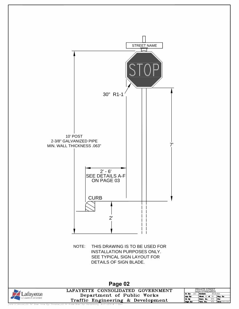
NOTE:THIS DRAWING IS TO BE USED FOR
INSTALLATION PURPOSES ONLY.
SEE TYPICAL SIGN LAYOUT FOR
DETAILS OF SIGN BLADE.
10' POST
2-3/8" GALVANIZED PIPE
MIN. WALL THICKNESS .063"
2'
CURB
2' - 6'
SEE DETAILS A-F
ON PAGE 03
7'
Page 02
30" R1-1
STREET NAME
NTS
NTS
JCV
0204
08-18-2015
PRIVATE STREET
SIGN STANDARDS
08-31-2015
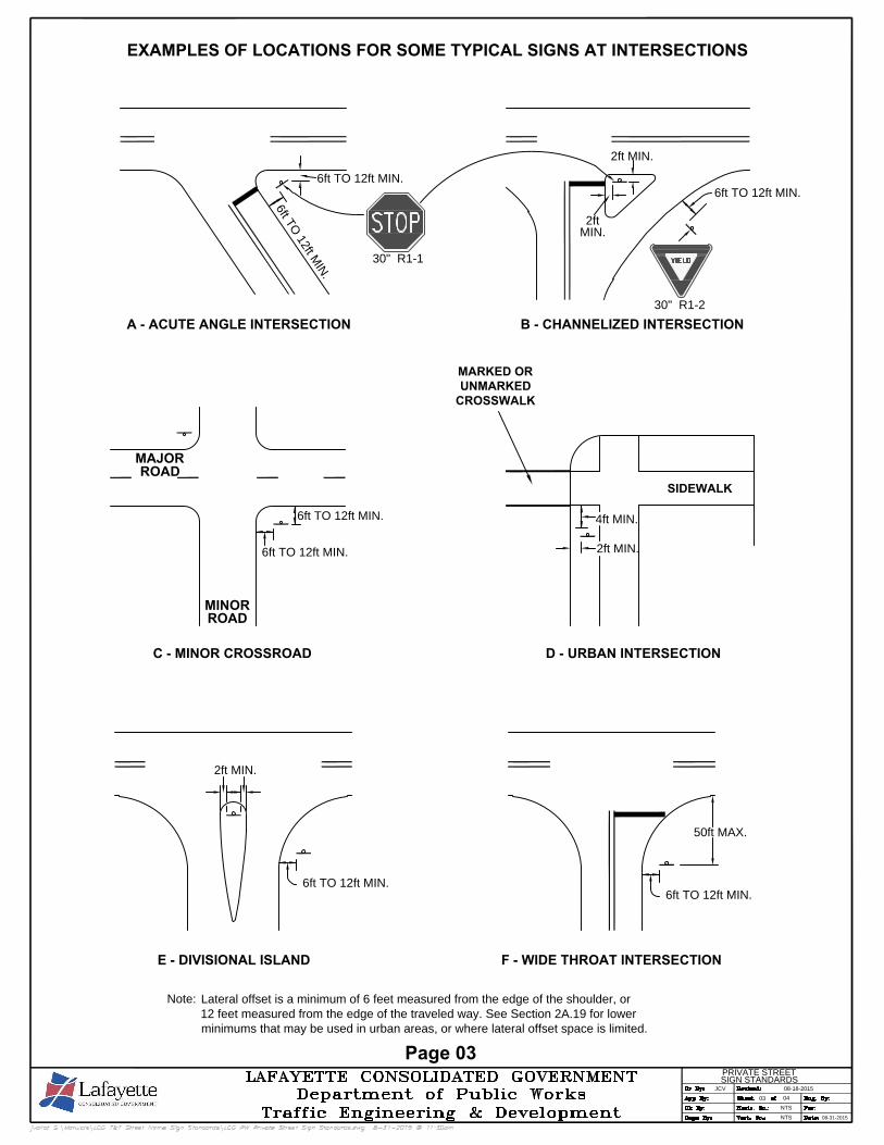
Note: Lateral offset is a minimum of 6 feet measured from the edge of the shoulder, or
12 feet measured from the edge of the traveled way. See Section 2A.19 for lower
minimums that may be used in urban areas, or where lateral offset space is limited.
E - DIVISIONAL ISLAND F - WIDE THROAT INTERSECTION
C - MINOR CROSSROAD
A - ACUTE ANGLE INTERSECTION
D - URBAN INTERSECTION
B - CHANNELIZED INTERSECTION
EXAMPLES OF LOCATIONS FOR SOME TYPICAL SIGNS AT INTERSECTIONS
6ft TO 12ft MIN.
2ft MIN.
6ft TO 12ft MIN.
50ft MAX.
MAJOR
ROAD
MINOR
ROAD
6ft TO 12ft MIN.
6ft TO 12ft MIN.
SIDEWALK
MARKED OR
UNMARKED
CROSSWALK
4ft MIN.
2ft MIN.
6ft TO 12ft MIN.
6
f
t
T
O
1
2
f
t
M
I
N
.
6ft TO 12ft MIN.
2ft MIN.
2ft
MIN.
Page 03
30" R1-1
30" R1-2
NTS
NTS
JCV
0304
08-18-2015
PRIVATE STREET
SIGN STANDARDS
08-31-2015
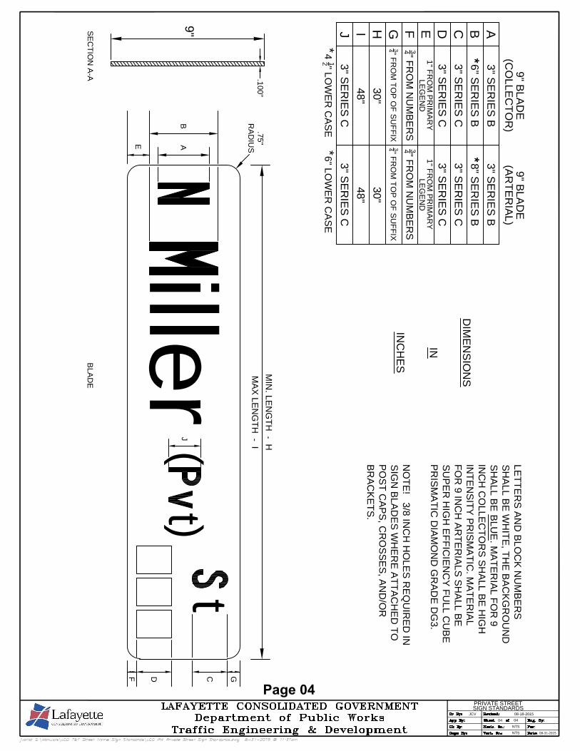
DIM
EN
SIO
NS
IN
IN
CH
ES
ABCDEF
GH
I
9" B
LA
DE
(C
OL
LE
CT
OR
)
9" B
LA
DE
(A
RT
ER
IA
L)
3" S
ER
IE
S B
6" S
ER
IE
S B
3" S
ER
IE
S C
3" S
ER
IE
S C
1" F
RO
M P
RIM
AR
Y
LE
GE
ND
34
" F
RO
M N
UM
BE
RS
34
" F
RO
M T
OP
O
F S
UF
FIX
30
"
48
"
3" S
ER
IE
S B
8" S
ER
IE
S B
3" S
ER
IE
S C
3" S
ER
IE
S C
1" F
RO
M P
RIM
AR
Y
LE
GE
ND
34
" F
RO
M N
UM
BE
RS
34
" F
RO
M T
OP
O
F S
UF
FIX
30
"
48
"
**
LE
TT
ER
S A
ND
B
LO
CK
N
UM
BE
RS
SH
ALL B
E W
HIT
E, T
HE
B
AC
KG
RO
UN
D
SH
ALL B
E B
LU
E. M
AT
ER
IA
L F
OR
9
IN
CH
C
OLLE
CT
OR
S S
HA
LL B
E H
IG
H
IN
TE
NS
IT
Y P
RIS
MA
TIC
. M
AT
ER
IA
L
FO
R 9 IN
CH
A
RT
ER
IA
LS
S
HA
LL B
E
SU
PE
R H
IG
H E
FF
IC
IE
NC
Y F
ULL C
UB
E
PR
IS
MA
TIC
D
IA
MO
ND
G
RA
DE
D
G3.
NO
TE
! 3/8 IN
CH
H
OLE
S R
EQ
UIR
ED
IN
SIG
N B
LA
DE
S W
HE
RE
A
TT
AC
HE
D T
O
PO
ST
C
AP
S, C
RO
SS
ES
, A
ND
/O
R
BR
AC
KE
TS
.
J3
" S
ER
IE
S C
3" S
ER
IE
S C
**
4
12
" LO
WE
R C
AS
E*
6" LO
WE
R C
AS
E*
9"
.100"
SE
CT
IO
N A
-A
MIN
. L
EN
GT
H - H
MA
X L
EN
GT
H - I
BLA
DE
BA
E
C GDF
iller
t
.75"
RA
DIU
S
( )
t
J
Page 04
NTS
NTS
0404
JCV
08-31-2015
08-18-2015
PRIVATE STREET
SIGN STANDARDS