PUBLIC HEALTH ENGINEERING DEPARTMENT GOVERNMENT OF BIHAR · 2019-09-17 · Public Health...
16
Protocol For ____________________________________________________________________________________________ OPERATION & MAINTENANCE AND REJECT MANAGEMENT PROTOCOL FOR ARSENIC, FLUORIDE AND IRON TREATMENT UNITS September 2019 PUBLIC HEALTH ENGINEERING DEPARTMENT GOVERNMENT OF BIHAR
Transcript of PUBLIC HEALTH ENGINEERING DEPARTMENT GOVERNMENT OF BIHAR · 2019-09-17 · Public Health...

Protocol For
____________________________________________________________________________________________
OPERATION & MAINTENANCE AND REJECT MANAGEMENT PROTOCOL FOR ARSENIC, FLUORIDE AND IRON TREATMENT UNITS
September 2019
PUBLIC HEALTH ENGINEERING DEPARTMENT
GOVERNMENT OF BIHAR

P a g e | 2
Contents
1.0 Introduction.......................................................................................................3 2.0 Arsenic, Fluoride and Iron removal technologies...........................................3 2.1 Arsenic Removal Technologies ....................................................................................3
2.2 Fluoride Removal Technologies....................................................................................4
2.3 Iron Removal Technologies...........................................................................................4
3.0 Operation and Maintenance of Treatment Unit.............................................5 3.1 Operation and Maintenance of Arsenic Treatment Unit............................................................9
3.2 Responsibilities of Contractors and Departmental Officers....................................................10
4.0 Reject Management of Treatment Units.......................................................11 4.1 Protocol for Reject Management, Spent Media Disposal and Handling, Backwash Water....11
4.2 Management of Backwash Water............................................................................................12
4.3 Design details of Sedimentation Tank and Sludge Storage Tank............................................12
5.0 Method for Supernatant Stream disposal from Sedimentation Tank and Sludge Disposal......................................................................................................15
P a g e | 3
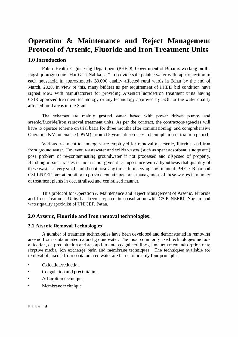
Operation & Maintenance and Reject Management Protocol of Arsenic, Fluoride and Iron Treatment Units
1.0 Introduction
Public Health Engineering Department (PHED), Government of Bihar is working on the flagship programme “Har Ghar Nal ka Jal” to provide safe potable water with tap connection to each household in approximately 30,000 quality affected rural wards in Bihar by the end of March, 2020. In view of this, many bidders as per requirement of PHED bid condition have signed MoU with manufacturers for providing Arsenic/Fluoride/Iron treatment units having CSIR approved treatment technology or any technology approved by GOI for the water quality affected rural areas of the State.
The schemes are mainly ground water based with power driven pumps and arsenic/fluoride/iron removal treatment units. As per the contract, the contractors/agencies will have to operate scheme on trial basis for three months after commissioning, and comprehensive Operation &Maintenance (O&M) for next 5 years after successful completion of trial run period.
Various treatment technologies are employed for removal of arsenic, fluoride, and iron from ground water. However, wastewater and solids wastes (such as spent adsorbent, sludge etc.) pose problem of re-contaminating groundwater if not processed and disposed of properly. Handling of such wastes in India is not given due importance with a hypothesis that quantity of these wastes is very small and do not pose any threat to receiving environment. PHED, Bihar and CSIR-NEERI are attempting to provide containment and management of these wastes in number of treatment plants in decentralised and centralised manner. This protocol for Operation & Maintenance and Reject Management of Arsenic, Fluoride and Iron Treatment Units has been prepared in consultation with CSIR-NEERI, Nagpur and water quality specialist of UNICEF, Patna.
2.0 Arsenic, Fluoride and Iron removal technologies:
2.1 Arsenic Removal Technologies
A number of treatment technologies have been developed and demonstrated in removing arsenic from contaminated natural groundwater. The most commonly used technologies include oxidation, co-precipitation and adsorption onto coagulated flocs, lime treatment, adsorption onto sorptive media, ion exchange resin and membrane techniques. The techniques available for removal of arsenic from contaminated water are based on mainly four principles:
• Oxidation/reduction
• Coagulation and precipitation
• Adsorption technique
• Membrane technique

P a g e | 4
2.2 Fluoride Removal Technologies
Defluoridation of drinking water is one of the option to overcome the problem of excessive fluoride in drinking water, where alternate source is not available. During the years following the discovery of fluoride as the cause of fluorosis, extensive research has been done on various methods for removal of fluoride from water and wastewater. While a number of technologies, based on adsorption and ion exchange in filter systems, coagulation and precipitation and membrane filtration processes have been developed and tested, sustainable implementation has rarely been achieved in rural communities. There are several defluoridation processes that have been tested globally. The common methods used for the removal of fluoride from drinking water are divided in the following categories:
• Ion-Exchange and Adsorption
• Coagulation and Precipitation
• Membrane Filtration Processes
2.3 Iron Removal Technologies
Iron in groundwater normally remains in dissolved state. When water is drawn through bore wells, oxygen from air gets dissolved in water and iron of ferrous state gets oxidized to ferric state and precipitates as suspended solids in water. Therefore, water, containing iron, slowly becomes turbid and highly unacceptable from an aesthetic view point. Oxidation by aeration or use of chemicals like chlorine, chlorine-dioxide or potassium permanganate followed by filtration alone or by settling and filtration can bring about the precipitation of iron and its removal. Similarly, zeolite as well as catalytic oxidation method is also being used for the removal of iron.
Some of the treatment methods for various forms of iron are as following:
• Aeration: Aeration brings water and air in close contact in order to remove dissolved metals (such as ferrous oxide) by oxidizing it to its ferric state, such as iron.
• Filtration: Filtration is technically defined as the process of separating suspended solid matter from a liquid, by causing the latter to pass through the pores of a membrane, called a filter.
• Water Softener: Water softening is a technique that serves the removal of the ions that cause the water to be hard, in most cases calcium and magnesium ions. Iron ions may also be removed during softening.
• Manganese Greensand: Manganese greensand is a specially processed medium for iron. This premium non-proprietary filter medium is processed from glauconitic greensand on which a shiny, hard finite thickness manganese oxide coating is formed and is firmly attached on every grain by a controlled process.
• Catalytic Filtration "BIRM": Birm is an efficient and economical method of removing dissolved iron compounds from raw water supplies. It may be used in either gravity-fed or pressurized water treatment systems. Birm acts as an insoluble catalyst to enhance the reaction between dissolved oxygen (D.O.) and the iron compounds.

P a g e | 5
• Ozonation: Ozone is not normally used for iron removal because ozone does not remove iron or manganese from water, but it can facilitate their removal. Ozone will oxidize these metals from dissolved forms to particulate (oxidized) forms.
• Ion Exchange: If dissolved iron oxidizes, fouling can occur on the surface of the resin as well as within the internal matrix of the bead. This type of fouling reduces resin capacity and can allow excess iron to bleed through the system. There are correction factors developed in the industry to help size softeners for iron removal.
• Sequestering: Adding chemical agents to water to keep metals like iron in solution to prevent characteristic red stains.
• Chlorination: Chlorine acts as a good oxidizing agent. Chemical oxidizer used to convert soluble iron to an insoluble, filterable form
• Electrolysis (electrolytic reaction): Electrolysis requires electrical current to be passed between an anode and cathode positioned in the water solution. This current creates positive and negative electrochemical charges that separates the water molecule into its component parts, oxygen and hydrogen gas. Being a larger, heavier molecule, oxygen will stay in solution, contributing to the dissolved oxygen content of the fluid, or will dissipate across the water-air interface. Hydrogen is smaller and lighter than oxygen and therefore leaves solution; it can be collected or allowed to dissipate into the atmosphere.
3.0 Operation and Maintenance of Treatment Unit: In an engineering sense, operation refers to hourly and daily operations of the components of a system such as plant, machinery, equipment, control valves etc. which is done by an operator or his assistant. This is a routine work. The term maintenance is defined as the act of keeping the plant, equipment, structures and other related facilities in optimum working order. Maintenance includes preventive maintenance or corrective maintenance of the system, mechanical adjustment, pipe line leakage repair, cleaning of storage tank, maintenance of the media (backwashing & regeneration/replacement) and reject- sludge management. Different manufacturers of treatment units adopt different technologies for removal of arsenic, fluoride and iron from ground water. Therefore, operation and maintenance of treatment units based on different technologies requires different methods. The life and contaminant removal efficiency of different media for different technologies are different.
In Bihar, treatment plants primarily utilize media/Nano-material/adsorbent based technologies depending on type of pollutants to be removed. Protocol provided below largely represents these technologies:
Operating protocol for filter and backwash of treatment units is as follows: 1. Make sure that the multiport valve of the Treatment unit is in “FILTER” mode and air release valve is open in case of manual air valve.

P a g e | 6
2. Start the unit by pressing the Green/power on button of the panel.
3. Treated water is discharged from the unit.
Backwash: Backwash must be done with treated water in case of arsenic and fluoride treatment units. In case of iron treatment plant backwash should be preferably be done using treated water to avoid build up of iron in backwash water. The treatment unit must be backwashed as per backwash interval with the following procedure.
1. Switch off the starter panel of the unit by pressing red/power off button.
2. Turn the multiport valve in “BACKWASH” configuration/mode.

P a g e | 7
3. Start the starter panel of the unit by pressing green/ power on button. The backwash will start and backwash water will go to the backwash pit/sedimentation tank.
4. Do backwash for required time as per protocol.
5. Switch off the starter panel of the unit by pressing red/ power off button.
6. Turn the multiport valve in “RINSE” configuration/mode.

P a g e | 8
7. Leave it for at least 2 minutes in “RINSE” configuration/mode. 8. Turn the multiport valve in “FILTER” Configuration/mode.
Note: 1. Never close the air release valve in case of manual air valve.
Note 2. Above pictures are indicative may vary based on different technologies.

P a g e | 9
3.1 Operation and Maintenance of Arsenic/Fluoride/Iron Treatment Unit: Contractor has to arrange skilled operator and other manpower to efficiently operate treatment plant in accordance with O&M protocol provided by respective manufacturer. The contractor shall ensure submission of O&M and Reject Management (Backwash water, supernatant water, sludge and exhausted media) protocol at the time of approval of design and drawing of treatment unit. Details of vessel-wise contents and its function should also be submitted by the contractor at the time of submission of Design & Drawing of treatment unit for approval in the format given below. Along with approval of Design & Drawing of treatment unit, approval of O&M and Reject Management (Backwash water, supernatant water, sludge and exhausted media) protocol and vessel-wise contents should also be approved by competent authority.
Name of manufacturer
Treatment Technology
Details of Material/Media in different vessels
Vessel 1 Vessel 2 Vessel 3
Media/ Material
Life Interval
of backwash
Interval of media
regeneration if required
Interval of media
replacement
Media/ Material
Life Interval
of backwash
Interval of media
regeneration if required
Interval of media
replacement
Media/ Material
Life Interval of backwash
Interval of media
regeneration if required
Interval of media
replacement
P a g e | 10
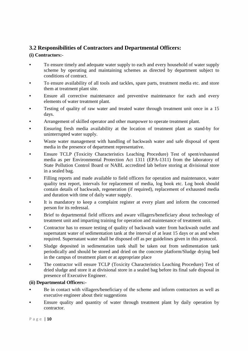
3.2 Responsibilities of Contractors and Departmental Officers: (i) Contractors:-
• To ensure timely and adequate water supply to each and every household of water supply scheme by operating and maintaining schemes as directed by department subject to conditions of contract.
• To ensure availability of all tools and tackles, spare parts, treatment media etc. and store them at treatment plant site.
• Ensure all corrective maintenance and preventive maintenance for each and every elements of water treatment plant.
• Testing of quality of raw water and treated water through treatment unit once in a 15 days.
• Arrangement of skilled operator and other manpower to operate treatment plant.
• Ensuring fresh media availability at the location of treatment plant as stand-by for uninterrupted water supply.
• Waste water management with handling of backwash water and safe disposal of spent media in the presence of department representative.
• Ensure TCLP (Toxicity Characteristics Leaching Procedure) Test of spent/exhausted media as per Environmental Protection Act 1311 (EPA-1311) from the laboratory of State Pollution Control Board or NABL accredited lab before storing at divisional store in a sealed bag.
• Filling reports and made available to field officers for operation and maintenance, water quality test report, intervals for replacement of media, log book etc. Log book should contain details of backwash, regeneration (if required), replacement of exhausted media and duration with time of daily water supply.
• It is mandatory to keep a complaint register at every plant and inform the concerned person for its redressal.
• Brief to departmental field officers and aware villagers/beneficiary about technology of treatment unit and imparting training for operation and maintenance of treatment unit.
• Contractor has to ensure testing of quality of backwash water from backwash outlet and supernatant water of sedimentation tank at the interval of at least 15 days or as and when required. Supernatant water shall be disposed off as per guidelines given in this protocol.
• Sludge deposited in sedimentation tank shall be taken out from sedimentation tank periodically and should be stored and dried on the concrete platform/Sludge drying bed in the campus of treatment plant or at appropriate place
• The contractor will ensure TCLP (Toxicity Characteristics Leaching Procedure) Test of dried sludge and store it at divisional store in a sealed bag before its final safe disposal in presence of Executive Engineer.
(ii) Departmental Officers:-
• Be in contact with villagers/beneficiary of the scheme and inform contractors as well as executive engineer about their suggestions
• Ensure quality and quantity of water through treatment plant by daily operation by contractor.

P a g e | 11
• Vigilant about daily/weekly/monthly operation of treatment plant.
• Vigilant about wastage of water through leakages and tap.
• Assistant Engineer/Junior Engineer will ensure to store exhausted media in the divisional store. If the quantity of exhausted media becomes significant, Executive Engineer will ensure its safe disposal in his presence through contractor.
• Executive Engineer will also ensure safe disposal of dried sludge in his presence through contractor after TCLP (Toxicity Characteristics Leaching Procedure) Test of sludge as per Environmental Protection Act 1311 (EPA-1311) from the laboratory of State Pollution Control Board or NABL accredited lab.
• Assistant Engineer will inspect backwashing of treatment unit once in two months. Similarly Junior Engineer will inspect backwashing of treatment unit once in a month.
• Replacement of media shall be done in presence of AE.
• To make sure the availability of fresh media with the contractor.
• Third party (from Government Organisation) evaluation of water treatment plants
4.0 Reject Management of Treatment Units
Waste streams in arsenic fluoride and iron, removal plants can be categorized as follows:
• Backwash wastewater stream
• Sludge from treatment reactors
• Spent adsorbents/Nano-materials and replaceable catalysts
Of all the treatment plants mentioned above, arsenic/fluoride poses maximum possibility of groundwater and soil contamination if not handled properly while iron removal plants generate more quantity of waste. Quality of sludge is not as hazardous as that of arsenic/fluoride removal plant and handling of waste from iron removal plants is easier; quantity of sludge/waste particularly in arsenic/fluoride removal plant is low as compared to arsenic and iron removal techniques.
Common options for waste generated are disposal in either municipal or hazardous waste landfills. Although landfills are supposed to properly provide engineered containment to keep leachate and wastes from re-entry into the environment, concerns remain about this practice of waste disposal in India. This has resulted in recommendations for waste disposal options such as mixing wastes with cow dung, stabilization in concrete, storage in dug or concrete lined pits, or storage in an aerated coarse sand filter.
Considering numerous water treatment plants likely to be installed in Bihar, it is proposed to develop scientifically designed disposal sites in each district for disposal of solid waste. Generic protocol for waste management is provided below: 4.1 Protocol for Reject Management, Spent Media Disposal and Handling, Backwash Water
• Backwash water generated from Arsenic, Fluoride and Iron, removal plant shall be analyzed, on weekly basis.
• Sedimentation tank shall be provided for the backwash water generated for the treatment unit.

P a g e | 12
• Dewatering of sludge shall be carried out by sand drying bed, freeze assisted sand beds, vacuum assisted bed, solar drying bed etc.
• Engineered landfills, if necessary, shall be designed for sludge generated for arsenic, fluoride or iron removal for working period of 15 years or for the period decided as per availability of land.
• Exhausted media of arsenic, fluoride removal shall be tested for the toxicity characteristics leaching prior to transport to the designated disposal facility.
• Supernatant after sedimentation and dewatering shall be tested before discharging into environment.
• Sedimentation tank and sludge storage facility shall be included as mandatory part of water treatment plant
4.2 Management of Backwash Water
The filter media can be cleaned periodically by backwashing (i.e. allowing the water to flow in the reverse direction). Filters should be backwashed until the backwash water is clean. During backwashing, the flow of water through the filter is reversed, i.e. water is forced from bottom to top cleaning out trapped particles. All the Filters are backwashed according to the necessity if head loss is observed to be high.
Backwash quantity is worked out based on 8 hour/day operation with average flow-rate of 10 m³/h and the average iron concentration of 5.0 mg/l. Amount of iron precipitates collected in sedimentation tank over a period of one year is estimated as:
5.0 g/m3 x 10 m3/hour x 8 hour/day x 365 days = 146 kg of iron/year Considering other particles in water such as manganese, sludge can by about 100 kg/year. It is necessary to provide sedimentation tank instead of soak-pit preferred by technology providers (agencies) to avoid seepage of iron back to groundwater. 4.3 Design details of Sedimentation Tank and Sludge Storage Tank
A) Sedimentation Tank with Sludge Storage Tank
Total Backwash water generated = 5 m3/day
Total volume of Sedimentation Tank including storage for sludge = 5.5 m3
Tank Dimension (RCC)
Length = 2.15 m Width = 2.15 m
Depth = 1.2 Freeboard = 0.3 m

P a g e | 13
B) Sludge Storage Facility- The dimensions of sludge storage facility given below is
indicative and may vary according to availability of land. Total sludge storage facility for 13 to 15 years
Total volume of sludge storage facility = 27 m3
Tank Dimension (RCC/Brick)
Length = 5 m
Breadth = 5 m
Depth = 1.5 m
The geo-membrane liner shall be used to restrict the percolation of leachate in the ground.
2.15m
2.15m

P a g e | 14

P a g e | 15
5.0 Method for Supernatant Stream disposal from Sedimentation Tank and Sludge Disposal.
Content Treatment method
Arsenic Stream Disposal
Sedimentation tank - Supernatant shall satisfy Effluent standards
Sludge Disposal
• Direct Landfill (pretreatment by lime) in Secured landfill
• Sludge reuse- building construction materials (bricks, etc)
Iron Stream Disposal
Sedimentation tank - Supernatant shall satisfy Effluent standards
Sludge Disposal
• Sludge to be land filled
Fluoride Stream Disposal
Sedimentation tank - Supernatant shall satisfy Effluent standards
Sludge Disposal
• Direct Landfill (pretreatment by lime) in secured land
• Sludge reuse- building construction materials (cement, bricks, etc), leaching of fluoride from cement composite ratio is 1:2
Recommendations (MOEFCC 2016)
Backwash Water- Sedimentation tank can be provided ensuring Supernatant shall satisfy Effluent standards of maximum permissible limit (mg/l) as below:
Parameters Into inland surface water On-land for irrigation
Arsenic 0.2 Not permitted
Iron 3 3
Fluoride 2 2
Sludge - Sludge shall satisfy standards for restricted landfills or will be used as construction material with the specified standards
Methods of Dewatering
Non-Mechanical Dewatering � Storage Ponds and Lagoons
� Drying Bed
• Sand Drying Beds
• Freeze-assisted Sand Beds
• Vacuum-assisted
• Solar Drying Beds

P a g e | 16
NOTE:
1. A possible long-term solution appears to be recycling of the sludge and using it for beneficial purposes. One technique that is available to treat hazardous waste is solidification that stabilizes and solidifies components of waste.
2. The solidified product is disposed off to a secure landfill site or it can be recycled as construction material like bricks if it meets the specific strength requirement and can be shown to leach toxic pollutants within acceptable limits.
3. This operation and maintenance and reject management protocol may further be revised/modified in future based on evaluation of functional treatment units and field experiences/innovations during running and O&M of treatment units.