PTP 800 & PTP 810 Ordering Guide - DoubleRadius · PTP 800 & PTP 810 ORDERING GUIDE ... If the PTP...
49
Issue 1.9 – 10/15/2012 PTP 800 & PTP 810 ORDERING GUIDE FROM PTP 800 05-00 and PTP 810 01-10 TM
Transcript of PTP 800 & PTP 810 Ordering Guide - DoubleRadius · PTP 800 & PTP 810 ORDERING GUIDE ... If the PTP...

Issue 1.9 – 10/15/2012
PTP 800 & PTP 810 ORDERING GUIDE FROM PTP 800 05-00 and PTP 810 01-10
TM
PAGE 2
ORDERING GUIDE PTP 800 & PTP 810
CONTENTSPG SECTION3 1. INTRODUCTION4 2. MODEMS4 2.1 PTP 800 COMPACT MODEM UNIT (CMU)4 2.2 PTP 810 MODULAR MODEM UNIT (MMU)4 2.2.1 PTP 810 MMU – STANDARD CONFIGURATION5 2.2.2 PTP 810 MMU – GIGE CONFIGURATION5 2.2.3 PTP 810 MMU – SUPER PDH CONFIGURATION6 2.3 CAPACITY KEYS6 2.3.1 ASYMMETRIC CAPACITY CONTROL (PTP 800 ONLY)6 2.3.2 CAPACITY UPGRADE OPTIONS7 2.3.3 PTP 810 CAPACITY KEYS12 2.3.4 PTP 810 XPIC13 2.4 ENCRYPTION FOR PTP80013 2.5 PTP 800 CMU ACCESSORIES13 2.5.1 OPTICAL INTERFACE13 2.5.2 PTP 800 CMU RACK MOUNT KIT13 2.5.3 PTP 800 AC/DC CONVERTER AND MAINS LEAD14 2.5.4 PTP 800 1+1 HOT STANDBY KITS14 2.6 PTP 810 MMU ACCESSORIES14 2.6.1 PTP 810 MMU SPARE MODULE CARDS15 2.6.2 PTP 810 MMU EXPANSION I/O MODULE15 2.6.3 PTP 810 MMU UPGRADE KIT15 2.6.4 PTP 810 AC/DC CONVERTER AND MAINS LEAD 15 2.6.5 OPTICAL INTERFACE16 3. RADIO FREQUENCY (RF) UNITS16 3.1 ODU-A AND ODU-B ORDERING GUIDANCE26 3.2 IRFU ORDERING GUIDANCE30 3.3 IRFU SPARE OPTIONS31 3.4 IRFU UPGRADE KIT OPTIONS32 4. ANTENNA & ANTENNA ACCESSORIES32 4.1 ODU MOUNTING OPTIONS33 4.2 IRFU MOUNTING OPTIONS34 4.3 ANTENNA OPTIONS39 4.4 ANTENNA ACCESSORIES39 4.4.1 ODU REMOTE MOUNTING KIT39 4.4.2 ODU COUPLER MOUNTING KIT40 4.4.3 ODU ORTHOGONAL MOUNTING KIT (OMK)41 4.4.4 FLEX WAVEGUIDE FOR ODU REMOTE MOUNTING41 4.4.5 ALL-INDOOR DEPLOYMENT RELATED MATERIALS44 5. CABLE AND CABLE ACCESSORIES44 5.1 IF CABLE BETWEEN IRFU AND MODEM UNIT44 5.2 IF CABLE BETWEEN ODU AND PTP 800 CMU OR PTP 810 MMU45 5.3 CABLE ASSEMBLY KIT45 5.4 LIGHTNING PROTECTION KIT46 5.5 CABLE GROUNDING KIT46 5.6 PTP 810 MMU CONSOLE PORT ADAPTER46 5.7 CRIMP TOOL46 5.8 HOISTING GRIP FOR CNT-400 CABLE46 6. SOFTWARE47 7. WARRANTY AND SERVICES47 7.1 STANDARD WARRANTY47 7.2 EXTENDED WARRANTY WITH ALL RISKS ADVANCED REPLACEMENT48 7.3 EXTENDED WARRANTY WITH REPAIR-AND-RETURN48 7.4 FCC MICROWAVE LICENSE COORDINATION SERVICES
PAGE 3
ORDERING GUIDE PTP 800 & PTP 810
1. INTRODUCTION
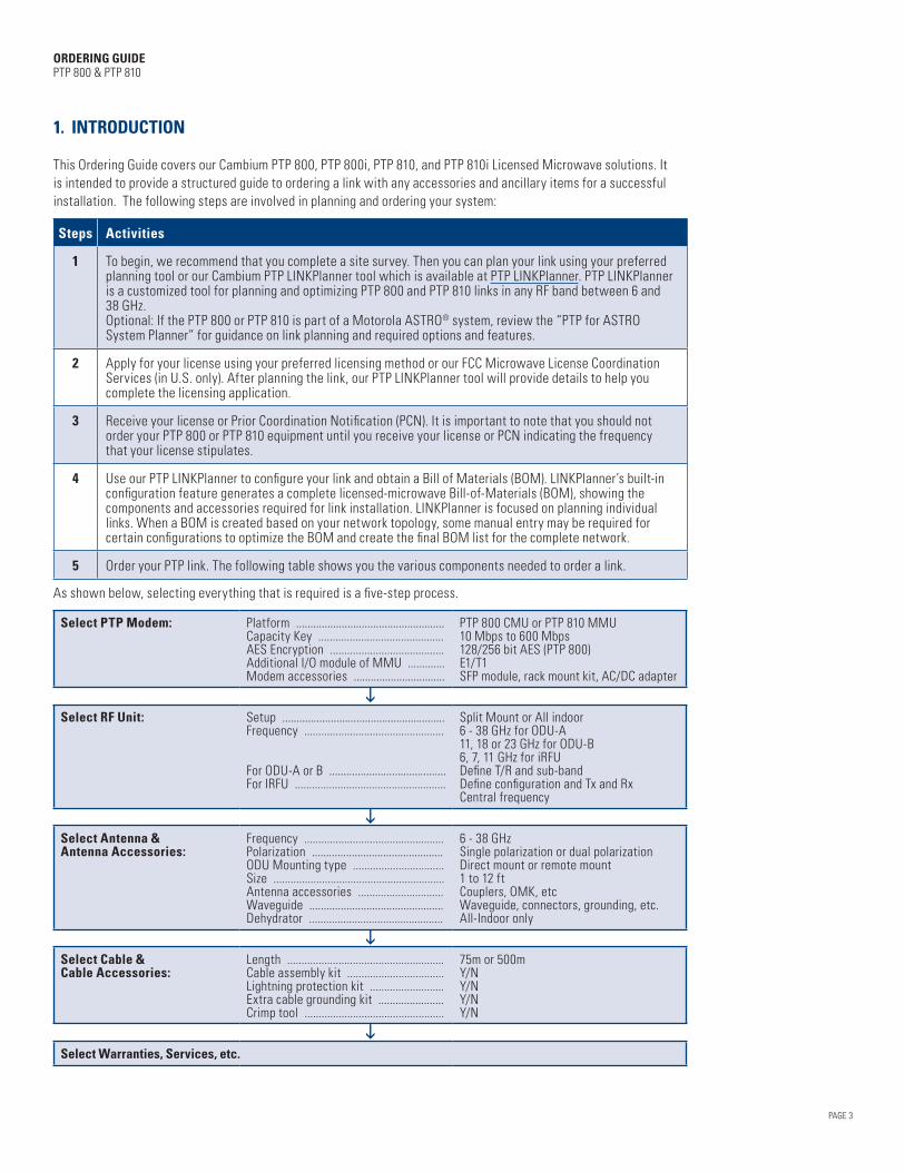
This Ordering Guide covers our Cambium PTP 800, PTP 800i, PTP 810, and PTP 810i Licensed Microwave solutions. It is intended to provide a structured guide to ordering a link with any accessories and ancillary items for a successful installation. The following steps are involved in planning and ordering your system:
Steps Activities
1 To begin, we recommend that you complete a site survey. Then you can plan your link using your preferred planning tool or our Cambium PTP LINKPlanner tool which is available at PTP LINKPlanner. PTP LINKPlanner is a customized tool for planning and optimizing PTP 800 and PTP 810 links in any RF band between 6 and 38 GHz.Optional: If the PTP 800 or PTP 810 is part of a Motorola ASTRO® system, review the “PTP for ASTRO System Planner” for guidance on link planning and required options and features.
2 Apply for your license using your preferred licensing method or our FCC Microwave License Coordination Services (in U.S. only). After planning the link, our PTP LINKPlanner tool will provide details to help you complete the licensing application.
3 Receive your license or Prior Coordination Notification (PCN). It is important to note that you should not order your PTP 800 or PTP 810 equipment until you receive your license or PCN indicating the frequency that your license stipulates.
4 Use our PTP LINKPlanner to configure your link and obtain a Bill of Materials (BOM). LINKPlanner’s built-in configuration feature generates a complete licensed-microwave Bill-of-Materials (BOM), showing the components and accessories required for link installation. LINKPlanner is focused on planning individual links. When a BOM is created based on your network topology, some manual entry may be required for certain configurations to optimize the BOM and create the final BOM list for the complete network.
5 Order your PTP link. The following table shows you the various components needed to order a link.
As shown below, selecting everything that is required is a five-step process.
Select PTP Modem: Platform ....................................................Capacity Key ............................................AES Encryption ........................................Additional I/O module of MMU .............Modem accessories ................................
PTP 800 CMU or PTP 810 MMU10 Mbps to 600 Mbps128/256 bit AES (PTP 800)E1/T1SFP module, rack mount kit, AC/DC adapter
iSelect RF Unit: Setup .........................................................
Frequency .................................................
For ODU-A or B .........................................For IRFU .....................................................
Split Mount or All indoor6 - 38 GHz for ODU-A11, 18 or 23 GHz for ODU-B6, 7, 11 GHz for iRFUDefine T/R and sub-bandDefine configuration and Tx and Rx Central frequency
iSelect Antenna & Antenna Accessories:
Frequency .................................................Polarization ..............................................ODU Mounting type ................................Size ............................................................Antenna accessories ..............................Waveguide ...............................................Dehydrator ...............................................
6 - 38 GHzSingle polarization or dual polarizationDirect mount or remote mount1 to 12 ftCouplers, OMK, etcWaveguide, connectors, grounding, etc.All-Indoor only
i Select Cable & Cable Accessories:
Length .......................................................Cable assembly kit ..................................Lightning protection kit ..........................Extra cable grounding kit .......................Crimp tool .................................................
75m or 500mY/NY/NY/NY/N
iSelect Warranties, Services, etc.

PAGE 4
ORDERING GUIDE PTP 800 & PTP 810
2. MODEMS
2.1 PTP 800 COMPACT MODEM UNIT (CMU) The PTP 800 CMU is frequency independent. Two CMUs are required for a single 1+0 link. Four CMUs are required for a 1+1 hot standby link. Each CMU package includes a wall-mount kit and a DC connector.
P/N Description
WB3480HH PTP 800 Modem 1000/100BaseT with Capacity Cap 10 Mbps
2.2 PTP 810 MODULAR MODEM UNIT (MMU)The PTP 810 MMU uses a modular architecture. Depending on your master I/O module, there are different base models for PTP 810 MMUs:• Standard – supports 2xFE + 16 E1/T1• Gig-E – supports 4 x GigE + 1 x GigE SFP slot + 2 E1/T1• Super PDH – supports 2xFE + 42 E1/T1
2.2.1 PTP 810 MMU - STANDARD CONFIGURATIONThe PTP 810 standard configuration supports:• 1 ~ 100 Mbps scalable Ethernet• 1 – 16 E1/T1: 2xE1/T1 (RJ-48C) and 14xE1/T1 (Molex 60-pin, high density) Depending on how many IF/Modem modules the MMU contains, there are two flavors under the PTP 810 MMU standard configuration:• The PTP 810 MMU Standard, 2xFE + 16xE1/T1, supports a 1+0 unprotected configuration.
• The PTP 810 MMU Standard Dual Modem, 2xFE + 16xE1/T1, supports 1+1, XPIC, 2+0 (East/East) for link aggregation, or 2+0 (East/West) for an unprotected Ribbon or Ring configuration.
P/N Release Description
C000081M001A PTP 810-01-00 PTP 810 MMU Standard, 2xFE + 16xE1/T1
C000081M003A PTP 810-01-00 PTP 810 MMU Standard Dual Modem, 2xFE + 16xE1/T1

PAGE 5
ORDERING GUIDE PTP 800 & PTP 810
2.2.2 PTP 810 MMU - GIGE CONFIGURATIONThe PTP 810 GigE configuration supports:• Gigabyte-scalable Ethernet (4xGigE + 1xGigE SFP Slot)• 2 x E1/T1 (RJ-48C)Depending on how many IF/Modem modules the MMU contains, there are two flavors under a PTP 810 MMU GigE configuration:• PTP 810 MMU GigE, 4xGigE + 1xGigE SFP + 2xE1/T1, supports a 1+0 unprotected configuration
• PTP 810 MMU GigE Dual Modem, 4xGigE + 1xGigE SFP + 2xE1/T1, supports 1+1, XPIC, 2+0 (East/East) for link aggregation or 2+0 (East/West) for unprotected Ribbon or Ring configuration.
P/N Release Description
C000081M008A PTP 810-01-00 PTP 810 MMU GigE, 4xGigE + 1xGigE SFP + 2xE1/T1
C000081M005A PTP 810-01-00 PTP 810 MMU GigE Dual Modem, 4xGigE + 1xGigE SFP + 2xE1/T1
2.2.3 PTP 810 MMU – SUPER PDH CONFIGURATIONThe PTP 810 Super PDH configuration supports:• 1 ~ 100 Mbps scalable Ethernet• 1 – 42 E1/T1: 3 x 14 E1/T1 (Molex 60-pin, high density)Depending on how many IF/Modem modules the MMU contains, there are two flavors under a PTP 810 MMU Super PDH configuration:• PTP 810 MMU Super PDH, 2xFE + 42xE1/T1, supports a 1+0 unprotected configuration
• PTP 810 MMU Super PDH Dual Modem, 2xFE + 42xE1/T1, supports 1+1, XPIC, 2+0 (East/East) for link aggregation or 2+0 (East/West) for unprotected ribbon or ring configuration
P/N Release Description
C000081M002A PTP 810 01-10 PTP810 MMU Super PDH, 2xFE + 42xE1/T1
C000081M010A PTP 810 01-10 PTP810 MMU Super PDH Dual Modem, 2xFE + 42xE1/T1
PAGE 6
ORDERING GUIDE PTP 800 & PTP 810
2.3 CAPACITY KEYSAll PTP 800 CMUs and PTP810 MMUs are set to a 10-Mbps capacity cap as the default from the factory. You can upgrade the throughput capacity to a greater capacity with a software license key. Capacity upgrades do not require any hardware changes.
Capacity-upgrade license keys are provided on a per-unit basis. While the PTP 800 and PTP 810 share the same capacity key structure, the modems use different methods to implement the capacity key.
For a PTP 800, the capacity key defines the maximum throughput capacity for all incoming traffic over the CMU’s Ethernet user port. This means that you can configure the link’s channel size and modulation with no limitation. However, the user throughput threshold on the Ethernet port is governed by the capacity key purchased.
For a PTP 810, the capacity key is mapped to the over-the-air maximum throughput capacity of the various modulation modes (i.e. channel size and modulation). The capacity key will enable a list of channel size and modulation mode combinations. So, you can ONLY configure the link’s channel size and modulation mode as permitted by the purchased capacity key.
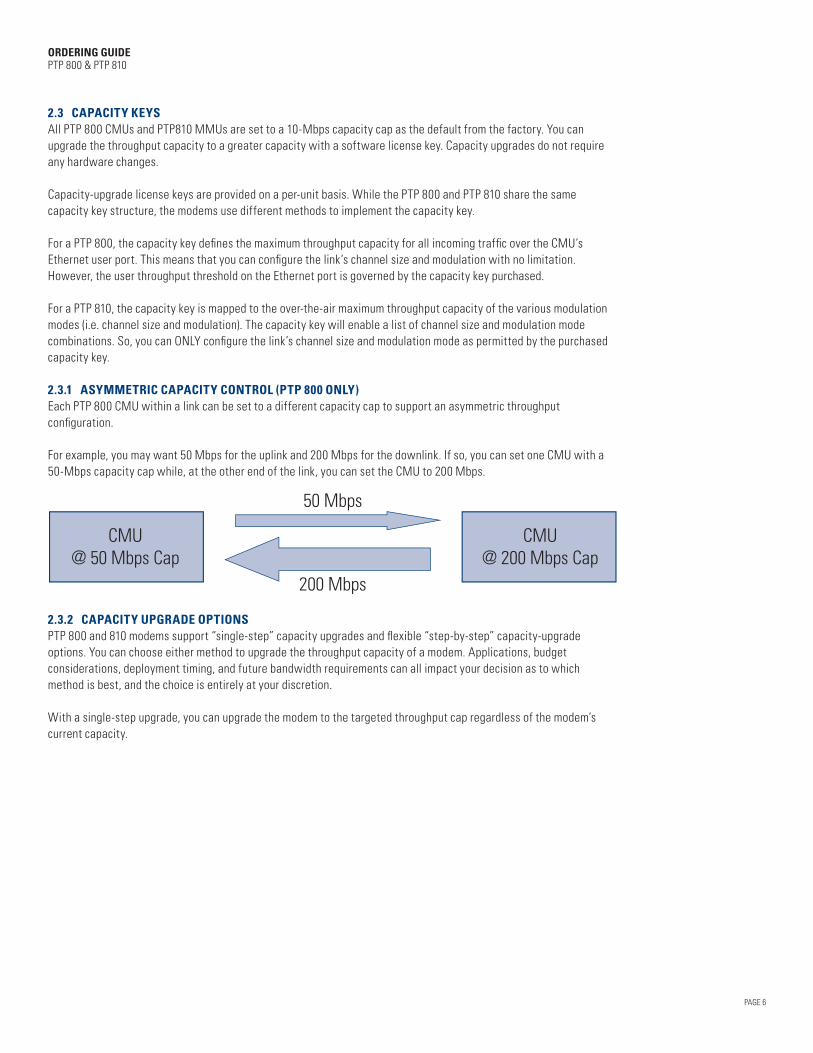
2.3.1 ASYMMETRIC CAPACITY CONTROL (PTP 800 ONLY)Each PTP 800 CMU within a link can be set to a different capacity cap to support an asymmetric throughput configuration.
For example, you may want 50 Mbps for the uplink and 200 Mbps for the downlink. If so, you can set one CMU with a 50-Mbps capacity cap while, at the other end of the link, you can set the CMU to 200 Mbps.
CMU@ 50 Mbps Cap
50 Mbps
200 Mbps
CMU@ 200 Mbps Cap
2.3.2 CAPACITY UPGRADE OPTIONS PTP 800 and 810 modems support “single-step” capacity upgrades and flexible “step-by-step” capacity-upgrade options. You can choose either method to upgrade the throughput capacity of a modem. Applications, budget considerations, deployment timing, and future bandwidth requirements can all impact your decision as to which method is best, and the choice is entirely at your discretion.
With a single-step upgrade, you can upgrade the modem to the targeted throughput cap regardless of the modem’s current capacity.

SINGLE-STEP CAPACITY UPGRADE
P/N Description
WB3538 PTP 800 / PTP 810 Modem Capacity CAP - 20 Mbps (per Unit)
WB3539 PTP 800 / PTP 810 Modem Capacity CAP - 30 Mbps (per Unit)
WB3540 PTP 800 / PTP 810 Modem Capacity CAP - 40 Mbps (per Unit)
WB3541 PTP 800 / PTP 810 Modem Capacity CAP - 50 Mbps (per Unit)
WB3542 PTP 800 / PTP 810 Modem Capacity CAP - 100 Mbps (per Unit)
WB3543 PTP 800 / PTP 810 Modem Capacity CAP - 150 Mbps (per Unit)
WB3544 PTP 800 / PTP 810 Modem Capacity CAP - 200 Mbps (per Unit)
WB3545 PTP 800 / PTP 810 Modem Capacity CAP - 300 Mbps (per Unit)
WB3546 PTP 800 / PTP 810 Modem Capacity CAP - 400 Mbps (per Unit)
N000081K001A PTP 810 Modem Capacity CAP - 600 Mbps (per Unit)
For a step-by-step upgrade, you can upgrade the modem over time from the current capacity to the next capacity level. The modem’s current capacity must match the throughput capacity of the license key.
STEP-BY-STEP CAPACITY UPGRADE
P/N Description
WB3547 PTP 800 / PTP 810 Modem Capacity CAP upgrade from 20 -> 30 Mbps key (per Unit)
WB3548 PTP 800 / PTP 810 Modem Capacity CAP upgrade from 30 -> 40 Mbps key (per Unit)
WB3549 PTP 800 / PTP 810 Modem Capacity CAP upgrade from 40 -> 50 Mbps key (per Unit)
WB3550 PTP 800 / PTP 810 Modem Capacity CAP upgrade from 50 -> 100 Mbps key (per Unit)
WB3551 PTP 800 / PTP 810 Modem Capacity CAP upgrade from 100 -> 150 Mbps key (per Unit)
WB3552 PTP 800 / PTP 810 Modem Capacity CAP upgrade from 150 -> 200 Mbps key (per Unit)
WB3553 PTP 800 / PTP 810 Modem Capacity CAP upgrade from 200 -> 300 Mbps key (per Unit)
WB3554 PTP 800 / PTP 810 Modem Capacity CAP upgrade from 300 -> 400 Mbps Key (per Unit)
N000081K003 PTP 810 Modem Capacity CAP upgrade from 400 -> 600 Mbps Key (per Unit)
2.3.3 PTP 810 CAPACITY KEYS The PTP 810 MMU capacity keys are issued in three different types:• 1+x (1+0 or 1+1):
– The “1+x” capacity key is used to allow operation of 1+0 and 1+1 link configurations of the PTP 810 MMU.• 2+0:
– The “2+0” capacity key is used to allow operation of 2+0 East/East (true 2+0 with link aggregation) and 2+0 East/West (1+0 Ring or 1+0 Ribbon) link configurations of the PTP 810 MMU.
• XPIC: – The “XPIC” capacity code type is used to allow operation of 2+0 XPIC link configurations of the PTP 810 MMU.
For customers who want to deploy XPIC, a separate XPIC authorization key also needs to be purchased, which can be found at Section 2.3.4.
PAGE 7
ORDERING GUIDE PTP 800 & PTP 810
PAGE 8
ORDERING GUIDE PTP 800 & PTP 810
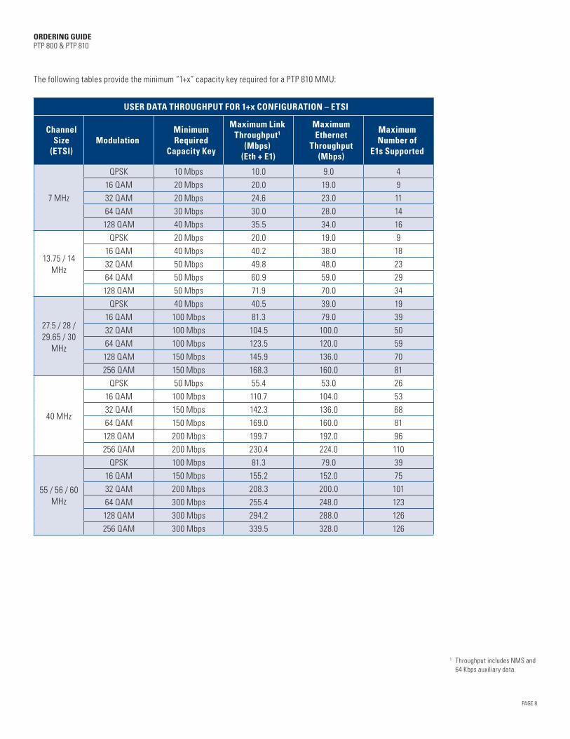
The following tables provide the minimum “1+x” capacity key required for a PTP 810 MMU:
USER DATA THROUGHPUT FOR 1+x CONFIGURATION – ETSI
Channel Size
(ETSI)Modulation
Minimum Required
Capacity Key
Maximum Link Throughput1
(Mbps) (Eth + E1)
Maximum Ethernet
Throughput (Mbps)
Maximum Number of
E1s Supported
7 MHz
QPSK 10 Mbps 10.0 9.0 4
16 QAM 20 Mbps 20.0 19.0 9
32 QAM 20 Mbps 24.6 23.0 11
64 QAM 30 Mbps 30.0 28.0 14
128 QAM 40 Mbps 35.5 34.0 16
13.75 / 14 MHz
QPSK 20 Mbps 20.0 19.0 9
16 QAM 40 Mbps 40.2 38.0 18
32 QAM 50 Mbps 49.8 48.0 23
64 QAM 50 Mbps 60.9 59.0 29
128 QAM 50 Mbps 71.9 70.0 34
27.5 / 28 / 29.65 / 30
MHz
QPSK 40 Mbps 40.5 39.0 19
16 QAM 100 Mbps 81.3 79.0 39
32 QAM 100 Mbps 104.5 100.0 50
64 QAM 100 Mbps 123.5 120.0 59
128 QAM 150 Mbps 145.9 136.0 70
256 QAM 150 Mbps 168.3 160.0 81
40 MHz
QPSK 50 Mbps 55.4 53.0 26
16 QAM 100 Mbps 110.7 104.0 53
32 QAM 150 Mbps 142.3 136.0 68
64 QAM 150 Mbps 169.0 160.0 81
128 QAM 200 Mbps 199.7 192.0 96
256 QAM 200 Mbps 230.4 224.0 110
55 / 56 / 60 MHz
QPSK 100 Mbps 81.3 79.0 39
16 QAM 150 Mbps 155.2 152.0 75
32 QAM 200 Mbps 208.3 200.0 101
64 QAM 300 Mbps 255.4 248.0 123
128 QAM 300 Mbps 294.2 288.0 126
256 QAM 300 Mbps 339.5 328.0 126
1 Throughput includes NMS and 64 Kbps auxiliary data.

PAGE 9
ORDERING GUIDE PTP 800 & PTP 810
USER DATA THROUGHPUT FOR 1+x CONFIGURATION – FCC
Channel Size (FCC)
ModulationMinimum Required
Capacity Key
Maximum Link Throughput
(Mbps) (Eth + T1)
Maximum Ethernet
Throughput (Mbps)
Maximum Number of
T1s Supported
10 MHz
QPSK 10 Mbps 13.8 13.0 816 QAM 30 Mbps 27.8 27.0 1732 QAM 30 Mbps 33.9 33.0 2164 QAM 40 Mbps 41.4 40.0 26128 QAM 50 Mbps 49.2 47.0 31
20 MHz
QPSK 30 Mbps 27.8 27.0 1716 QAM 50 Mbps 55.7 54.0 3532 QAM 50 Mbps 68.8 67.0 4364 QAM 100 Mbps 84.0 82.0 53128 QAM 100 Mbps 99.3 96.0 63256 QAM 100 Mbps 114.5 104.0 73
25 MHz
QPSK 40 Mbps 34.7 33.0 2116 QAM 100 Mbps 69.6 67.0 4432 QAM 100 Mbps 89.5 87.0 5764 QAM 100 Mbps 105.7 100.0 67128 QAM 150 Mbps 124.9 120.0 80256 QAM 150 Mbps 144.1 136.0 92
30 MHz
QPSK 40 Mbps 41.6 40.0 2616 QAM 100 Mbps 83.5 81.0 5332 QAM 100 Mbps 107.4 104.0 6864 QAM 150 Mbps 134.4 128.0 86128 QAM 150 Mbps 149.9 144.0 96256 QAM 150 Mbps 173.0 168.0 110
40 MHz
QPSK 50 Mbps 55.7 54.0 3516 QAM 100 Mbps 111.4 104.0 7132 QAM 150 Mbps 143.2 136.0 9164 QAM 150 Mbps 170.0 160.0 109128 QAM 200 Mbps 200.8 192.0 126256 QAM 200 Mbps 231.7 224.0 126
50 MHz
QPSK 50 Mbps 69.6 67.0 4416 QAM 150 Mbps 139.2 136.0 8932 QAM 200 Mbps 178.9 168.0 11464 QAM 200 Mbps 218.7 208.0 126128 QAM 300 Mbps 252.0 240.0 126256 QAM 300 Mbps 290.7 280.0 126
80 MHz
QPSK 100 Mbps 81.3 79.0 5116 QAM 150 Mbps 162.5 152.0 10432 QAM 200 Mbps 208.9 200.0 12564 QAM 300 Mbps 255.4 248.0 126128 QAM 300 Mbps 294.2 288.0 126256 QAM 300 Mbps 339.5 328.0 126
PAGE 10
ORDERING GUIDE PTP 800 & PTP 810
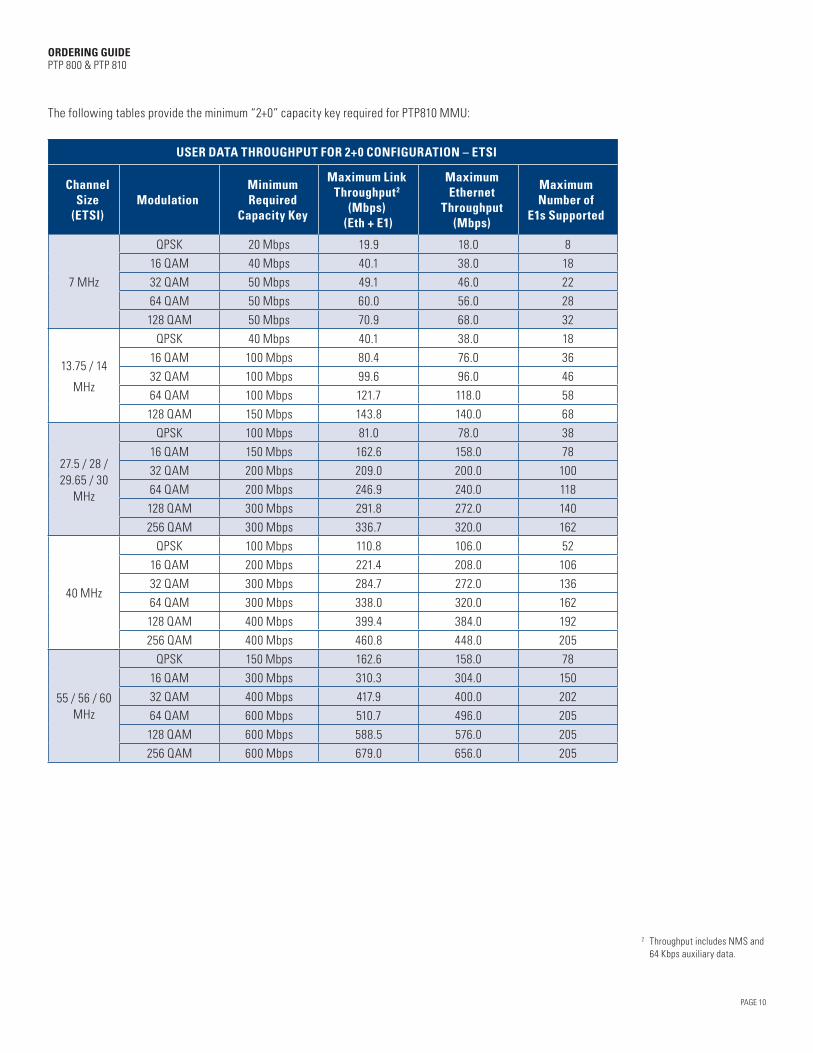
The following tables provide the minimum “2+0” capacity key required for PTP810 MMU:
USER DATA THROUGHPUT FOR 2+0 CONFIGURATION – ETSI
Channel Size
(ETSI)Modulation
Minimum Required
Capacity Key
Maximum Link Throughput2
(Mbps) (Eth + E1)
Maximum Ethernet
Throughput (Mbps)
Maximum Number of
E1s Supported
7 MHz
QPSK 20 Mbps 19.9 18.0 8
16 QAM 40 Mbps 40.1 38.0 18
32 QAM 50 Mbps 49.1 46.0 22
64 QAM 50 Mbps 60.0 56.0 28
128 QAM 50 Mbps 70.9 68.0 32
13.75 / 14
MHz
QPSK 40 Mbps 40.1 38.0 18
16 QAM 100 Mbps 80.4 76.0 36
32 QAM 100 Mbps 99.6 96.0 46
64 QAM 100 Mbps 121.7 118.0 58
128 QAM 150 Mbps 143.8 140.0 68
27.5 / 28 / 29.65 / 30
MHz
QPSK 100 Mbps 81.0 78.0 38
16 QAM 150 Mbps 162.6 158.0 78
32 QAM 200 Mbps 209.0 200.0 100
64 QAM 200 Mbps 246.9 240.0 118
128 QAM 300 Mbps 291.8 272.0 140
256 QAM 300 Mbps 336.7 320.0 162
40 MHz
QPSK 100 Mbps 110.8 106.0 52
16 QAM 200 Mbps 221.4 208.0 106
32 QAM 300 Mbps 284.7 272.0 136
64 QAM 300 Mbps 338.0 320.0 162
128 QAM 400 Mbps 399.4 384.0 192
256 QAM 400 Mbps 460.8 448.0 205
55 / 56 / 60 MHz
QPSK 150 Mbps 162.6 158.0 78
16 QAM 300 Mbps 310.3 304.0 150
32 QAM 400 Mbps 417.9 400.0 202
64 QAM 600 Mbps 510.7 496.0 205
128 QAM 600 Mbps 588.5 576.0 205
256 QAM 600 Mbps 679.0 656.0 205
2 Throughput includes NMS and 64 Kbps auxiliary data.

PAGE 11
ORDERING GUIDE PTP 800 & PTP 810
USER DATA THROUGHPUT FOR 2+0 CONFIGURATION – FCC
Channel Size (FCC)
ModulationMinimum Required
Capacity Key
Maximum Link Throughput
(Mbps) (Eth + T1)
Maximum Ethernet
Throughput (Mbps)
Maximum Number of
T1s Supported
10 MHz
QPSK 30 Mbps 27.6 24.0 1616 QAM 50 Mbps 55.5 52.0 3432 QAM 50 Mbps 67.8 64.0 4264 QAM 100 Mbps 82.8 80.0 52128 QAM 100 Mbps 98.3 94.0 62
20 MHz
QPSK 50 Mbps 55.5 52.0 3416 QAM 100 Mbps 111.4 108.0 7032 QAM 150 Mbps 137.5 134.0 8664 QAM 150 Mbps 168.0 162.0 106128 QAM 200 Mbps 198.5 192.0 126256 QAM 200 Mbps 229.1 208.0 146
25 MHz
QPSK 50 Mbps 69.4 66.0 4216 QAM 150 Mbps 139.2 135.0 8832 QAM 200 Mbps 179.0 174.0 11464 QAM 200 Mbps 211.4 200.0 134128 QAM 300 Mbps 249.9 240.0 160256 QAM 300 Mbps 288.3 272.0 184
30 MHz
QPSK 100 Mbps 83.2 80.0 5216 QAM 150 Mbps 167.1 162.0 10632 QAM 200 Mbps 214.8 208.0 13664 QAM 300 Mbps 268.8 256.0 172128 QAM 300 Mbps 299.8 288.0 192256 QAM 300 Mbps 345.9 336.0 205
40 MHz
QPSK 100 Mbps 111.4 108.0 7016 QAM 200 Mbps 222.7 208.0 14232 QAM 300 Mbps 286.3 272.0 18264 QAM 300 Mbps 339.9 320.0 205128 QAM 400 Mbps 401.7 384.0 205256 QAM 400 Mbps 463.5 448.0 205
50 MHz
QPSK 150 Mbps 139.2 134.0 8816 QAM 300 Mbps 278.4 272.0 17832 QAM 400 Mbps 357.9 336.0 20564 QAM 400 Mbps 437.3 416.0 205128 QAM 600 Mbps 503.9 480.0 205256 QAM 600 Mbps 581.4 560.0 205
80 MHz
QPSK 150 Mbps 162.6 158.0 10216 QAM 300 Mbps 325.0 304.0 20532 QAM 400 Mbps 417.9 400.0 20564 QAM 600 Mbps 510.7 496.0 205128 QAM 600 Mbps 588.5 576.0 205256 QAM 600 Mbps 679.0 656.0 205
PAGE 12
ORDERING GUIDE PTP 800 & PTP 810
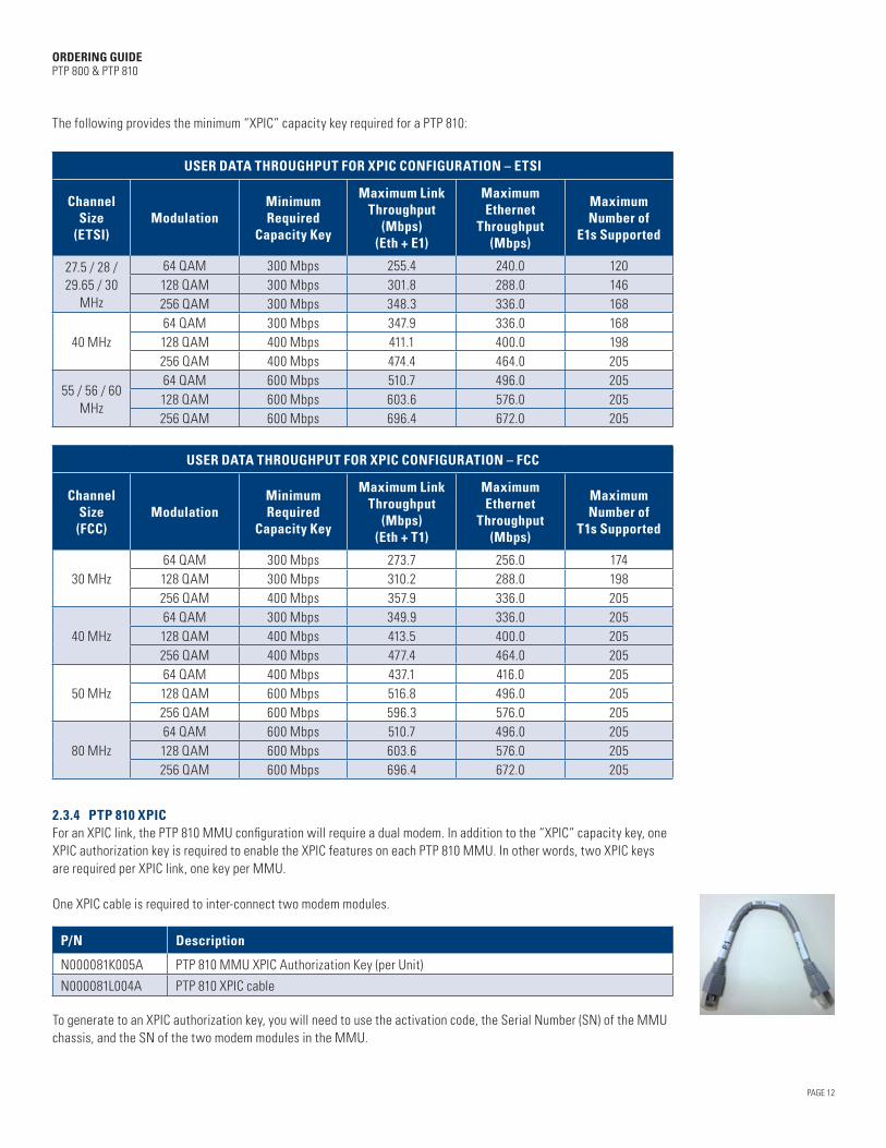
The following provides the minimum “XPIC” capacity key required for a PTP 810:
USER DATA THROUGHPUT FOR XPIC CONFIGURATION – ETSI
Channel Size
(ETSI)Modulation
Minimum Required
Capacity Key
Maximum Link Throughput
(Mbps) (Eth + E1)
Maximum Ethernet
Throughput (Mbps)
Maximum Number of
E1s Supported
27.5 / 28 / 29.65 / 30
MHz
64 QAM 300 Mbps 255.4 240.0 120128 QAM 300 Mbps 301.8 288.0 146256 QAM 300 Mbps 348.3 336.0 168
40 MHz64 QAM 300 Mbps 347.9 336.0 168128 QAM 400 Mbps 411.1 400.0 198256 QAM 400 Mbps 474.4 464.0 205
55 / 56 / 60 MHz
64 QAM 600 Mbps 510.7 496.0 205128 QAM 600 Mbps 603.6 576.0 205256 QAM 600 Mbps 696.4 672.0 205
USER DATA THROUGHPUT FOR XPIC CONFIGURATION – FCC
Channel Size (FCC)
ModulationMinimum Required
Capacity Key
Maximum Link Throughput
(Mbps) (Eth + T1)
Maximum Ethernet
Throughput (Mbps)
Maximum Number of
T1s Supported
30 MHz64 QAM 300 Mbps 273.7 256.0 174128 QAM 300 Mbps 310.2 288.0 198256 QAM 400 Mbps 357.9 336.0 205
40 MHz64 QAM 300 Mbps 349.9 336.0 205128 QAM 400 Mbps 413.5 400.0 205256 QAM 400 Mbps 477.4 464.0 205
50 MHz64 QAM 400 Mbps 437.1 416.0 205128 QAM 600 Mbps 516.8 496.0 205256 QAM 600 Mbps 596.3 576.0 205
80 MHz64 QAM 600 Mbps 510.7 496.0 205128 QAM 600 Mbps 603.6 576.0 205256 QAM 600 Mbps 696.4 672.0 205
2.3.4 PTP 810 XPIC For an XPIC link, the PTP 810 MMU configuration will require a dual modem. In addition to the “XPIC” capacity key, one XPIC authorization key is required to enable the XPIC features on each PTP 810 MMU. In other words, two XPIC keys are required per XPIC link, one key per MMU.
One XPIC cable is required to inter-connect two modem modules.
P/N Description
N000081K005A PTP 810 MMU XPIC Authorization Key (per Unit)
N000081L004A PTP 810 XPIC cable
To generate to an XPIC authorization key, you will need to use the activation code, the Serial Number (SN) of the MMU chassis, and the SN of the two modem modules in the MMU.
PAGE 13
ORDERING GUIDE PTP 800 & PTP 810
2.4 ENCRYPTION FOR PTP 800PTP 800 systems support 128-bit and 256-bit AES encryption as security options. The encryption is enabled via a license key which unlocks the functionality in the CMU. The AES license key is provided on a per-unit basis. AES is used for link encryption, but also for SNMPv3 Privacy (SNMP encryption) and HTTPS (secure management web-page access).
For Motorola ASTRO® implementations using Unified Event Manager (UEM) to manage PTP 800 radios, HTTPS is mandatory and SNMPv3 Privacy is optional. For ASTRO implementations using UEM, AES is required for secure SNMPv3 operation (as opposed to “Clear” operation).
P/N Description
WB3555 PTP 800 Series AES License Key 128bit - End only
WB3556 PTP 800 Series AES License Key 256bit - End only
2.5 PTP 800 CMU ACCESSORIES
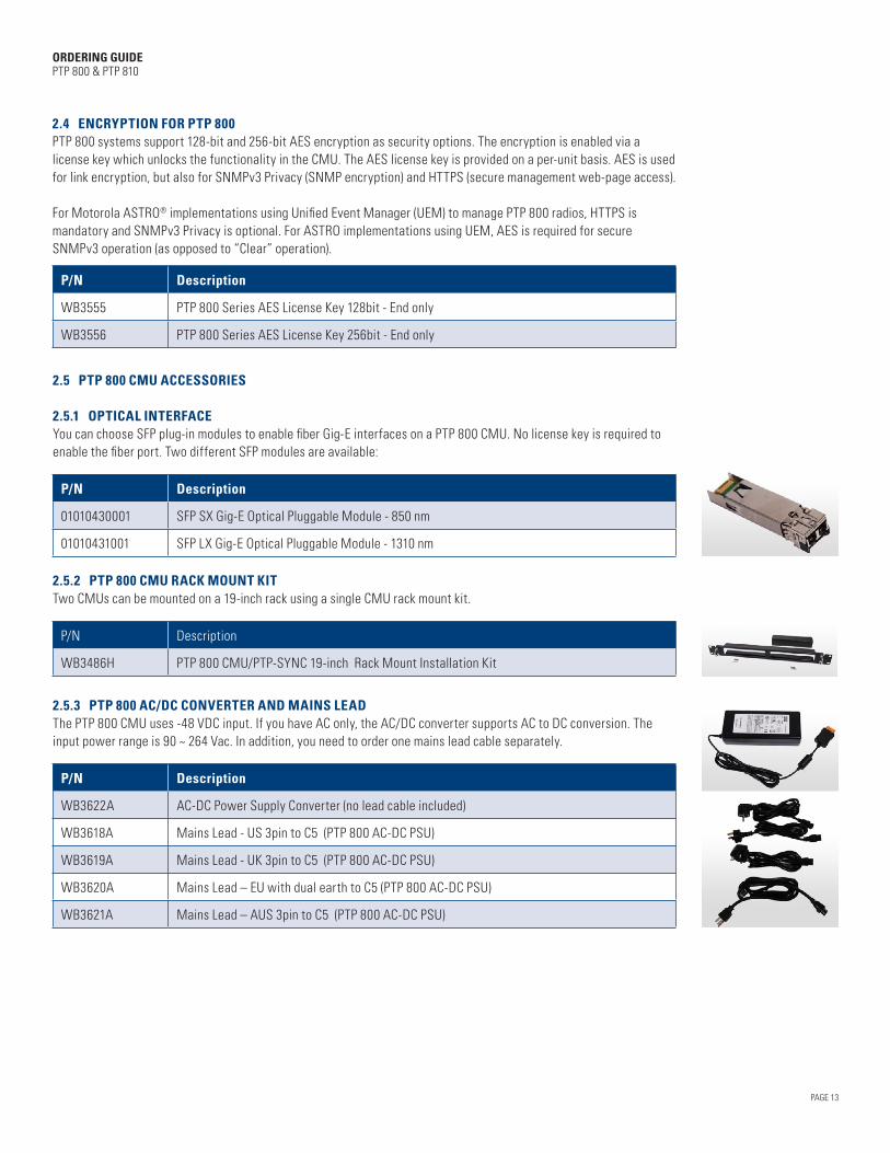
2.5.1 OPTICAL INTERFACE You can choose SFP plug-in modules to enable fiber Gig-E interfaces on a PTP 800 CMU. No license key is required to enable the fiber port. Two different SFP modules are available:
P/N Description
01010430001 SFP SX Gig-E Optical Pluggable Module - 850 nm
01010431001 SFP LX Gig-E Optical Pluggable Module - 1310 nm
2.5.2 PTP 800 CMU RACK MOUNT KIT Two CMUs can be mounted on a 19-inch rack using a single CMU rack mount kit.
P/N Description
WB3486H PTP 800 CMU/PTP-SYNC 19-inch Rack Mount Installation Kit
2.5.3 PTP 800 AC/DC CONVERTER AND MAINS LEAD The PTP 800 CMU uses -48 VDC input. If you have AC only, the AC/DC converter supports AC to DC conversion. The input power range is 90 ~ 264 Vac. In addition, you need to order one mains lead cable separately.
P/N Description
WB3622A AC-DC Power Supply Converter (no lead cable included)
WB3618A Mains Lead - US 3pin to C5 (PTP 800 AC-DC PSU)
WB3619A Mains Lead - UK 3pin to C5 (PTP 800 AC-DC PSU)
WB3620A Mains Lead – EU with dual earth to C5 (PTP 800 AC-DC PSU)
WB3621A Mains Lead – AUS 3pin to C5 (PTP 800 AC-DC PSU)

PAGE 14
ORDERING GUIDE PTP 800 & PTP 810
2.5.4 PTP 800 1+1 HOT STANDBY KITS You may need to purchase a 1+1 Protection Kit for certain configurations. Two different Protection Kits are supported for the PTP 800: • 1+1 Protection Kit – Optical-Y: For 1+1 Optical-Y configurations, one kit is required per end. The kit includes two
850 nm multi-mode Gig-E SFP modules and two, two-meter Fiber Gig-E Y-cables (one cable for the Tx split and one cable for the Rx split).
• 1+1 Protection Kit – Out-of-Band Management (OOBM): For 1+1 OOBM configurations, one kit is required per end. The kit includes one 4 RJ-45 port box which is used to split the OOBM from the CMU management port.
1+1 Optical-Y Splitter Kit
P/N Description
WB3806H 1+1 Optical-Y Splitter Kit (per end, includes SFP modules – 850 nm)
WB3807H 1+1 Out-of-Band Splitter Kit (per end)
2.6 PTP 810 MMU ACCESSORIES
2.6.1 PTP 810 MMU SPARE MODULE CARDSThe PTP 810 has a modular achitecture. In the case of hardware failure, there is no need to exchange the complete MMU, only the defected module or chassis would need to be replaced.
The following provides the PNs for the spare cards and chassis.
P/N Description
N000081H005A PTP 810 MMU Control Module
C000081H002A PTP 810 MMU Modem Module
N000081H015A PTP 810 MMU Power Supply Module
N000081H004A PTP 810 MMU Chassis
N000081H016A PTP 810 MMU Standard Master I/O module
N000081H012A PTP 810 MMU GigE Master I/O module
PTP 810 MMU Control Module
PTP 810 MMU Modem Module
PTP 810 MMU Power Supply Module
PTP 810 MMU Chassis
PTP 810 MMU Standard Master I/O Module PTP 810 MMU GigE Master I/O Module
PTP 810 MMU GigE Master I/O Module (Top View)
PTP 810 MMU Super PDH Master I/O Module
1+1 Out-of-Band Splitter
PAGE 15
ORDERING GUIDE PTP 800 & PTP 810
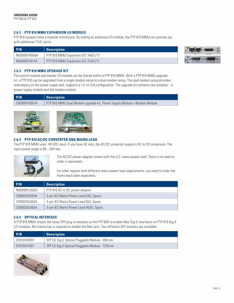
2.6.2 PTP 810 MMU EXPANSION I/O MODULEPTP 810 systems have a modular achitecture. By adding an addtional I/O module, the PTP 810 MMU can provide you with additional T1/E1 ports.
P/N Description
N000081H006A PTP 810 MMU Expansion I/O: 16xE1/T1
N000081H011A PTP 810 MMU Expansion I/O: 21xE1/T1
2.6.3 PTP 810 MMU UPGRADE KITThe control module and master I/O module can be shared within a PTP 810 MMU. With a PTP 810 MMU upgrade kit, a PTP 810 can be upgraded from a single modem setup to a dual modem setup. The dual modem setup provides redundancy on the power supply and supports a 1+1 or 2+0 configuration. The upgrade kit contains two modules – a power supply module and the modem module.
P/N Description
C000081H001A PTP 810 MMU Dual Modem upgrade kit, Power Supply Module + Modem Module
2.6.4 PTP 810 AC/DC CONVERTER AND MAINS LEADThe PTP 810 MMU uses -48 VDC input. If you have AC only, the AC/DC converter supports AC to DC conversion. The input power range is 90 ~ 264 Vac.
The AC/DC power adapter comes with the U.S. mains power lead. There is no need to order it separately.
For other regions with different mains power lead requirements, you need to order the mains lead cable separately.
P/N Description
N000081L002A PTP 810 AC to DC power adaptor
C000025L003A 3-pin IEC Mains Power Lead (UK), Spare
C000025L004A 3-pin IEC Mains Power Lead (EU), Spare
C000025L005A 3-pin IEC Mains Power Lead (AUS), Spare
2.6.5 OPTICAL INTERFACEA PTP 810 MMU shares the same SFP plug-in modules as the PTP 800 to enable fiber Gig-E interfaces on PTP 810 Gig-E I/O modules. No license key is required to enable the fiber port. Two different SFP modules are available:
P/N Description
01010430001 SFP SX Gig-E Optical Pluggable Module - 850 nm
01010431001 SFP LX Gig-E Optical Pluggable Module - 1310 nm

PAGE 16
ORDERING GUIDE PTP 800 & PTP 810
3. RADIO FREQUENCY (RF) UNITS
The PTP 800 and PTP 810 support the same RF Units (ODU-A, ODU-B and IRFU), with various frequency and configurations for different network requirements.
Configuration Components
Split-Mount Installation
Supported by both PTP800 CMU and PTP810 MMU:• ODU-A (6-38 GHz, ETSI & FCC/IC ) • ODU-B (11/18/23 GHz, FCC/IC only)
PTP800 CMU to ODU Connection: Coaxial Cable, N-type (CMU) to N-type (ODU) connectors
PTP 810 MMU to ODU Connection: Coaxial Cable, TNC-type (MMU) to N-type (ODU) connectors
All-Indoor Installation
Supported by both PTP 800 CMU and PTP 810 MMU:• IRFU (FCC/IC 6 and 11 GHz, FCC 7 GHz)
PTP 800 CMU to IRFU Connection: Coaxial Cable, N-type (CMU) to SMA (IRFU) connectors
PTP 810 MMU to IRFU Connection: Coaxial Cable, TNC-type (MMU) to SMA (IRFU) connectors
ODU-A IRFU ODU-B
3.1 ODU-A AND ODU-B ORDERING GUIDANCE
ODU-A and ODU-B are designed for split-mount installation with the ODU installed outdoors. The ODU can be directly attached to the antenna or remote mounted using a short flexible waveguide that is connected to the antenna.
If you want to deploy the 6 and 11 GHz ODU-A in an all-indoor installation with an elliptical waveguide, please consult your Cambium Regional Technical Manager for detailed guidance.
ODU-A all indoor installation is only supported by PTP800 CMU. We do not recommend using the ODU-B for any all-indoor installation.
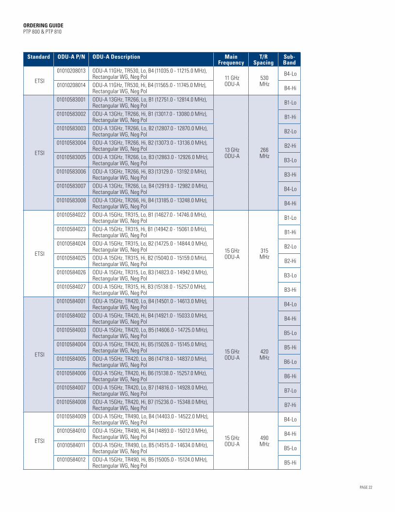
To order the correct ODU SKUs, you must choose the correct T/R spacing that complies with local regulatory rules and the correct sub-band that covers the channel frequency you have licensed. For a complete link, the ODUs must be ordered in pairs, with one end on Tx-Hi and one end on Tx-Lo, such as:
SAMPLE ODU PAIRING
ODU-A 18GHz, TR1560, Lo, B3 (17700.0 - 18140.0 MHz), Rectangular WG, Neg Pol
ODU-A 18GHz, TR1560, Hi, B3 (19260.0 - 19700.0 MHz), Rectangular WG, Neg Pol

PAGE 17
ORDERING GUIDE PTP 800 & PTP 810
ODU-A and ODU-B share the same antenna interface with the same mechanical size of mounting clips. When compared with ODU-A, ODU-B offers higher transmit power, lower power consumption and less weight.• ODU-B shares the same antenna interface as ODU-A and can be direct mounted with all Mot-interface antennas.• ODU-B supports FCC/IC 11, 18 and 23 GHz.• ODU-B supports the same channel plan, bandwidth and modulation as ODU-A on 11, 18 and 23 GHz bands, • The FCC-regulation 18 GHz ODU-B supports the 80 MHz channel from QPSK up to 256 QAM.• ODU-B has higher transmit power than ODU-A: – For FCC/IC 11 GHz, the maximum transmit power is increased by 1 dB @ 64/128/256 QAM. – For FCC/IC 18 and 23 GHz, the maximum transmit power is increased by 2 dB @ 64/128/256 QAM.• ODU-B is “greener and lighter” than ODU-A: – As much as 29% less power consumption – As much as 15% less weight
The following tables provide ODU-A and ODU-B ordering information.
Standard ODU-A P/N ODU-A Description MainFrequency
T/RSpacing
Sub-Band
ETSI&
FCC
01010411007 ODU-A 6GHz,TR252, Lo, B1 (5925.0 - 6025.0 MHz), Rectangular WG, Neg Pol
L6ODU-A
252.04 MHz
B1-Lo
01010411008 ODU-A 6GHz,TR252, Hi, B1 (6175.0- 6275.0 MHz), Rectangular WG, Neg Pol B1-Hi
01010411009 ODU-A 6GHz,TR252, Lo, B2 (6000.0 - 6100.0 MHz), Rectangular WG, Neg Pol B2-Lo
01010411010 ODU-A 6GHz,TR252, Hi, B2 (6250.0 - 6350.0 MHz), Rectangular WG, Neg Pol B2-Hi
01010411011 ODU-A 6GHz,TR252, Lo, B3 (6075.0 - 6175.0 MHz), Rectangular WG, Neg Pol B3-Lo
01010411012 ODU-A 6GHz,TR252, Hi, B3 (6325.0 - 6425.0 MHz), Rectangular WG, Neg Pol B3-Hi
FCC
01010411024 ODU-A GHz, TR160, Lo, B1 (6580.0 – 6640.0 MHz), Rectangular WB, Neg Pol
U6ODU-A
160 MHz
B1-Lo
01010411022 ODU-A GHz, TR160, Hi, B1 (6740.0 – 6800.0 MHz), Rectangular WB, Neg Pol B1-Hi
01010411025 ODU-A GHz, TR160, Lo, B2 (6640.0 – 6710.0 MHz), Rectangular WB, Neg Pol B2-Lo
01010411023 ODU-A GHz, TR160, Hi, B2 (6800.0 – 6870.0 MHz), Rectangular WB, Neg Pol B2-Hi
FCC
01010411027 ODU-A GHz, TR170, Lo, B1 (6530.0 – 6580.0 MHz), Rectangular WB, Neg Pol U6
ODU-A170 MHz
B1-Lo
01010411026 ODU-A GHz, TR170, Hi, B1 (6700.0 – 6750.0 MHz), Rectangular WB, Neg Pol B1-Hi
ETSI
01010411013 ODU-A 6GHz, TR340, Lo, B1 (6430.0 - 6540.0 MHz), Rectangular WG, Neg Pol
U6ODU-A
340MHz
B1-Lo
01010411014 ODU-A 6GHz, TR340, Hi, B1 (6770.0 - 6880.0 MHz), Rectangular WG, Neg Pol B1-Hi
01010411015 ODU-A 6GHz, TR340, Lo, B2 (6520.0 - 6630.0 MHz), Rectangular WG, Neg Pol B2-Lo
01010411016 ODU-A 6GHz, TR340, Hi, B2 (6860.0 - 6970.0 MHz), Rectangular WG, Neg Pol B2-Hi
01010411017 ODU-A 6GHz, TR340, Lo, B3 (6600.0 - 6710.0 MHz), Rectangular WG, Neg Pol B3-Lo
01010411018 ODU-A 6GHz, TR340, Hi, B3 (6940.0 - 7050.0 MHz), Rectangular WG, Neg Pol B3-Hi
01010411019 ODU-A 6GHz, TR340, Lo, B4 (6670.0 - 6780.0 MHz), Rectangular WG, Neg Pol B4-Lo
01010411020 ODU-A 6GHz, TR340, Hi, B4 (7010.0 - 7120.0 MHz), Rectangular WG, Neg Pol B4-Hi

PAGE 18
ORDERING GUIDE PTP 800 & PTP 810
Standard ODU-A P/N ODU-A Description MainFrequency
T/RSpacing
Sub-Band
ETSI
01010610001 ODU-A 7GHz, TR154, Lo, B1 (7428.0 - 7484.0 MHz), Circular WG, Neg Pol
7 GHzODU-A
154MHz
B1-Lo
01010610002 ODU-A 7GHz, TR154, Hi, B1 (7582.0 - 7638.0 MHz), Circular WG, Neg Pol B1-Hi
01010610003 ODU-A 7GHz, TR154, Lo, B2 (7470.0 - 7526.0 MHz), Circular WG, Neg Pol B2-Lo
01010610004 ODU-A 7GHz, TR154, Hi, B2 (7624.0 - 7680.0 MHz), Circular WG, Neg Pol B2-Hi
01010610005 ODU-A 7GHz, TR154, Lo, B3 (7512.0 - 7568.0 MHz), Circular WG, Neg Pol B3-Lo
01010610006 ODU-A 7GHz, TR154, Hi, B3 (7666.0 - 7722.0 MHz), Circular WG, Neg Pol B3-Hi
ETSI
01010610013 ODU-A 7GHz, TR161, Lo, B1 (7114.0 - 7177.0 MHz), Circular WG, Neg Pol
7 GHzODU-A
161MHz
B1-Lo
01010610014 ODU-A 7GHz, TR161, Hi, B1 (7275.0 - 7338.0 MHz), Circular WG, Neg Pol B1-Hi
01010610015 ODU-A 7GHz, TR161, Lo, B2 (7149.0 - 7212.0 MHz), Circular WG, Neg Pol B2-Lo
01010610016 ODU-A 7GHz, TR161, Hi, B2 (7310.0 - 7373.0 MHz), Circular WG, Neg Pol B2-Hi
01010610017 ODU-A 7GHz, TR161, Lo, B3 (7184.0 - 7247.0 MHz), Circular WG, Neg Pol B3-Lo
01010610018 ODU-A 7GHz, TR161, Hi, B3 (7345.0 - 7408.0 MHz), Circular WG, Neg Pol B3-Hi
01010610019 ODU-A 7GHz, TR161, Lo, B4 (7219.0 - 7282.0 MHz), Circular WG, Neg Pol B4-Lo
01010610020 ODU-A 7GHz, TR161, Hi, B4 (7380.0 - 7443.0 MHz), Circular WG, Neg Pol B4-Hi
01010610021 ODU-A 7GHz, TR161, Lo, B5 (7239.0 - 7302.0 MHz), Circular WG, Neg Pol B5-Lo
01010610022 ODU-A 7GHz, TR161, Hi, B5 (7400.0 - 7463.0 MHz), Circular WG, Neg Pol B5-Hi
01010610023 ODU-A 7GHz, TR161, Lo, B6 (7274.0 - 7337.0 MHz), Circular WG, Neg Pol B6-Lo
01010610024 ODU-A 7GHz, TR161, Hi, B6 (7435.0 - 7498.0 MHz), Circular WG, Neg Pol B6-Hi
01010610025 ODU-A 7GHz, TR161, Lo, B7 (7309.0 - 7372.0 MHz), Circular WG, Neg Pol B7-Lo
01010610026 ODU-A 7GHz, TR161, Hi, B7 (7470.0 - 7533.0 MHz), Circular WG, Neg Pol B7-Hi
01010610027 ODU-A 7GHz, TR161, Lo, B8 (7344.0 - 7407.0 MHz), Circular WG, Neg Pol B8-Lo
01010610028 ODU-A 7GHz, TR161, Hi, B8 (7505.0 - 7568.0 MHz), Circular WG, Neg Pol B8-Hi
01010610029 ODU-A 7GHz, TR161, Lo, B9 (7414.0 - 7477.0 MHz), Circular WG, Neg Pol B9-Lo
01010610030 ODU-A 7GHz, TR161, Hi, B9 (7575.0 - 7638.0 MHz), Circular WG, Neg Pol B9-Hi
01010610031 ODU-A 7GHz, TR161, Lo, B10 (7449.0 - 7512.0 MHz), Circular WG, Neg Pol B10-Lo
01010610032 ODU-A 7GHz, TR161, Hi, B10 (7610.0 - 7673.0 MHz), Circular WG, Neg Pol B10-Hi
01010610033 ODU-A 7GHz, TR161, Lo, B21 (7484.0 - 7547.0 MHz), Circular WG, Neg Pol B21-Lo
01010610034 ODU-A 7GHz, TR161, Hi, B21 (7645.0 - 7708.0 MHz), Circular WG, Neg Pol B21-Hi

PAGE 19
ORDERING GUIDE PTP 800 & PTP 810
Standard ODU-A P/N ODU-A Description MainFrequency
T/RSpacing
Sub-Band
ETSI
01010610035 ODU-A 7GHz, TR161, Lo, B22 (7519.0 - 7582.0 MHz), Circular WG, Neg Pol
7 GHzODU-A
161MHz
B22-Lo
01010610036 ODU-A 7GHz, TR161, Hi, B22 (7680.0 - 7743.0 MHz), Circular WG, Neg Pol B22-Hi
01010610037 ODU-A 7GHz, TR161, Lo, B23 (7539.0 - 7602.0 MHz), Circular WG, Neg Pol B23-Lo
01010610038 ODU-A 7GHz, TR161, Hi, B23 (7700.0 - 7763.0 MHz), Circular WG, Neg Pol B23-Hi
01010610039 ODU-A 7GHz, TR161, Lo, B24 (7574.0 - 7637.0 MHz), Circular WG, Neg Pol B24-Lo
01010610040 ODU-A 7GHz, TR161, Hi, B24 (7735.0 - 7798.0 MHz), Circular WG, Neg Pol B24-Hi
01010610041 ODU-A 7GHz, TR161, Lo, B25 (7609.0 - 7672.0 MHz), Circular WG, Neg Pol B25-Lo
01010610042 ODU-A 7GHz, TR161, Hi, B25 (7770.0 - 7833.0 MHz), Circular WG, Neg Pol B25-Hi
01010610043 ODU-A 7GHz, TR161, Lo, B26 (7644.0 - 7707.0 MHz), Circular WG, Neg Pol B26-Lo
01010610044 ODU-A 7GHz, TR161, Hi, B26 (7805.0 - 7868.0 MHz), Circular WG, Neg Pol B26-Hi
ETSI
01010610062 ODU-A 7GHz, TR168, Lo, B1 (7443.0 - 7499.0 MHz), Circular WG, Neg Pol
7 GHzODU-A
168MHz
B1-Lo
01010610063 ODU-A 7GHz, TR168, Hi, B1 (7611.0 - 7667.0 MHz), Circular WG, Neg Pol B1-Hi
01010610064 ODU-A 7GHz, TR168, Lo, B2 (7485.0 - 7541.0 MHz), Circular WG, Neg Pol B2-Lo
01010610065 ODU-A 7GHz, TR168, Hi, B2 (7653.0 - 7709.0 MHz), Circular WG, Neg Pol B2-Hi
01010610066 ODU-A 7GHz, TR168, Lo, B3 (7527.0 - 7583.0 MHz), Circular WG, Neg Pol B3-Lo
01010610067 ODU-A 7GHz, TR168, Hi, B3 (7695.0 - 7751.0 MHz), Circular WG, Neg Pol B3-Hi
ETSI
01010610045 ODU-A 7GHz, TR196, Lo, B1 (7093.0 - 7149.0 MHz), Circular WG, Neg Pol
7 GHzODU-A
196MHz
B1-Lo
01010610046 ODU-A 7GHz, TR196, Hi, B1 (7289.0 - 7345.0 MHz), Circular WG, Neg Pol B1-Hi
01010610047 ODU-A 7GHz, TR196, Lo, B2 (7121.0 - 7177.0 MHz), Circular WG, Neg Pol B2-Lo
01010610048 ODU-A 7GHz, TR196, Hi, B2 (7317.0 - 7373.0 MHz), Circular WG, Neg Pol B2-Hi
01010610049 ODU-A 7GHz, TR196, Lo, B3 (7149.0 - 7205.0 MHz), Circular WG, Neg Pol B3-Lo
01010610050 ODU-A 7GHz, TR196, Hi, B3 (7345.0 - 7401.0 MHz), Circular WG, Neg Pol B3-Hi
01010610051 ODU-A 7GHz, TR196, Lo, B4 (7177.0 - 7233.0 MHz), Circular WG, Neg Pol B4-Lo
01010610052 ODU-A 7GHz, TR196, Hi, B4 (7373.0 - 7429.0 MHz), Circular WG, Neg Pol B4-Hi
01010610053 ODU-A 7GHz, TR196, Lo, B5 (7205.0 - 7261.0 MHz), Circular WG, Neg Pol B5-Lo
01010610054 ODU-A 7GHz, TR196, Hi, B5 (7401.0 - 7457.0 MHz), Circular WG, Neg Pol B5-Hi
ETSI
01010610055 ODU-A 7GHz, TR245, Lo, B1 (7400.0 - 7484.0 MHz), Circular WG, Neg Pol 7 GHz
ODU-A245MHz
B1-Lo
01010610056 ODU-A 7GHz, TR245, Hi, B1 (7645.0 - 7729.0 MHz), Circular WG, Neg Pol B1-Hi

PAGE 20
ORDERING GUIDE PTP 800 & PTP 810
Standard ODU-A P/N ODU-A Description MainFrequency
T/RSpacing
Sub-Band
ETSI
01010610057 ODU-A 7GHz, TR245, Lo, B2 (7484.0 - 7568.0 MHz), Circular WG, Neg Pol
7 GHzODU-A
245MHz
B2-Lo
01010610058 ODU-A 7GHz, TR245, Hi, B2 (7729.0 - 7813.0 MHz), Circular WG, Neg Pol B2-Hi
01010610059 ODU-A 7GHz, TR245, Lo, B3 (7568.0 - 7652.0 MHz), Circular WG, Neg Pol B3-Lo
01010610060 ODU-A 7GHz, TR245, Hi, B3 (7813.0 - 7897.0 MHz), Circular WG, Neg Pol B3-Hi
NTIA
01010610068 ODU-A 7 GHz, TR300, Lo, B1 (7090.0 – 7210.0 MHz) Circular WG, Neg Pol
7 GHzODU-A
300MHz
B1-Lo
01010610069 ODU-A 7 GHz, TR300, Hi, B1 (7390.0 – 7510.0 MHz) Circular WG, Neg Pol B1-Hi
01010610070 ODU-A 7 GHz, TR300, Lo, B2 (7210.0 – 7330.0 MHz) Circular WG, Neg Pol B2-Lo
01010610071 ODU-A 7 GHz, TR300, Hi, B2 (7510.0 – 7630.0 MHz) Circular WG, Neg Pol B2-Hi
01010610072 ODU-A 7 GHz, TR300, Lo, B3 (7330.0 – 7450.0 MHz) Circular WG, Neg Pol B3-Lo
01010610073 ODU-A 7 GHz, TR300, Hi, B3 (7630.0 – 7750.0 MHz) Circular WG, Neg Pol B3-Hi
ETSI
01010611001 ODU-A 8GHz, TR119 / 126, Lo, B1 (8279.0 - 8307.0 MHz), Circular WG, Neg Pol
8 GHzODU-A
119 & 126 MHz
B1-Lo
01010611002 ODU-A 8GHz, TR119 / 126, Hi, B1 (8398.0 - 8426.0 MHz), Circular WG, Neg Pol B1-Hi
01010611003 ODU-A 8GHz, TR119 / 126, Lo, B2 (8293.0 - 8321.0 MHz), Circular WG, Neg Pol B2-Lo
01010611004 ODU-A 8GHz, TR119 / 126, Hi, B2 (8412.0 - 8440.0 MHz), Circular WG, Neg Pol B2-Hi
01010611005 ODU-A 8GHz, TR119 / 126, Lo, B3 (8307.0 - 8335.0 MHz), Circular WG, Neg Pol B3-Lo
01010611006 ODU-A 8GHz, TR119 / 126, Hi, B3 (8426.0 - 8454.0 MHz), Circular WG, Neg Pol B3-Hi
01010611007 ODU-A 8GHz, TR119 / 126, Lo, B4 (8321.0 - 8349.0 MHz), Circular WG, Neg Pol B4-Lo
01010611008 ODU-A 8GHz, TR119 / 126, Hi, B4 (8440.0 - 8468.0 MHz), Circular WG, Neg Pol B4-Hi
01010611009 ODU-A 8GHz, TR119 / 126, Lo, B5 (8335.0 - 8363.0 MHz), Circular WG, Neg Pol B5-Lo
01010611010 ODU-A 8GHz, TR119 / 126, Hi, B5 (8454.0 - 8482.0 MHz), Circular WG, Neg Pol B5-Hi
01010611011 ODU-A 8GHz, TR119 / 126, Lo, B6 (8349.0 - 8377.0 MHz), Circular WG, Neg Pol B6-Lo
01010611012 ODU-A 8GHz, TR119 / 126, Hi, B6 (8468.0 - 8496.0 MHz), Circular WG, Neg Pol B6-Hi
ETSI
01010611019 ODU-A 8GHz, TR208, Lo, B1 (8043.0 - 8113.0 MHz), Circular WG, Neg Pol
8 GHzODU-A
208MHz
B1-Lo
01010611020 ODU-A 8GHz, TR208, Hi, B1 (8251.0 - 8321.0 MHz), Circular WG, Neg Pol B1-Hi
01010611021 ODU-A 8GHz, TR208, Lo, B2 (8099.0 - 8169.0 MHz), Circular WG, Neg Pol B2-Lo
01010611022 ODU-A 8GHz, TR208, Hi, B2 (8307.0 - 8377.0 MHz), Circular WG, Neg Pol B2-Hi
01010611023 ODU-A 8GHz, TR208, Lo, B3 (8155.0 - 8225.0 MHz), Circular WG, Neg Pol B3-Lo
01010611024 ODU-A 8GHz, TR208, Hi, B3 (8363.0 - 8433.0 MHz), Circular WG, Neg Pol B3-Hi

PAGE 21
ORDERING GUIDE PTP 800 & PTP 810
Standard ODU-A P/N ODU-A Description MainFrequency
T/RSpacing
Sub-Band
ETSI
01010611025 ODU-A 8GHz, TR208, Lo, B4 (8211.0 - 8281.0 MHz), Circular WG, Neg Pol 8 GHz
ODU-A208MHz
B4-Lo
01010611026 ODU-A 8GHz, TR208, Hi, B4 (8419.0 - 8489.0 MHz), Circular WG, Neg Pol B4-Hi
ETSI
01010611027 ODU-A 8GHz, TR266, Lo, B1 (7905.0 - 8024.0 MHz), Circular WG, Neg Pol
8 GHzODU-A
266MHz
B1-Lo
01010611028 ODU-A 8GHz, TR266, Hi, B1 (8171.0 - 8290.0 MHz), Circular WG, Neg Pol B1-Hi
01010611029 ODU-A 8GHz, TR266, Lo, B2 (8017.0 - 8136.0 MHz), Circular WG, Neg Pol B2-Lo
01010611030 ODU-A 8GHz, TR266, Hi, B2 (8283.0 - 8402.0 MHz), Circular WG, Neg Pol B2-Hi
ETSI
01010611031 ODU-A 8GHz, TR311, Lo, B2 (7835.0 - 7971.0 MHz), Circular WG, Neg Pol
8 GHzODU-A
311.32 MHz
B2-Lo
01010611032 ODU-A 8GHz, TR311, Hi, B2 (8146.0 - 8282.0 MHz), Circular WG, Neg Pol B2-Hi
01010611033 ODU-A 8GHz, TR311, Lo, B3 (7717.0 - 7867.0 MHz), Circular WG, Neg Pol B3-Lo
01010611034 ODU-A 8GHz, TR311, Hi, B3 (8028.0 - 8178.0 MHz), Circular WG, Neg Pol B3-Hi
NTIA
01010611036 ODU-A 8 GHz, TR360, Lo, B1 (7750.0 – 7870.0 MHz), Circular WG, Net Pol
8 GHzODU-A
360MHz
B1-Lo
01010611037 ODU-A 8 GHz, TR360, Hi, B1 (8110.0 – 8230.0 MHz), Circular WG, Net Pol B1-Hi
01010611038 ODU-A 8 GHz, TR360, Lo, B2 (7870.0 – 7990.0 MHz), Circular WG, Net Pol B2-Lo
01010611039 ODU-A 8 GHz, TR360, Hi, B2 (8230.0 – 8350.0 MHz), Circular WG, Net Pol B2-Hi
01010611040 ODU-A 8 GHz, TR360, Lo, B3 (7990.0 – 8110.0 MHz), Circular WG, Net Pol B3-Lo
01010611041 ODU-A 8 GHz, TR360, Hi, B3 (8350.0 – 8470.0 MHz), Circular WG, Net Pol B3-Hi
FCC&
ETSI
1010208001 ODU-A 11GHz, TR 490 & 500, Lo, B5 (10700.0 - 10890.0 MHz), Rectangular WG, Neg Pol
11 GHzODU-A
490 &500MHz
B5-Lo
1010208002 ODU-A 11GHz, TR 490 & 500, Hi, B5 (11200.0 - 11390.0 MHz), Rectangular WG, Neg Pol B5-Hi
1010208003 ODU-A 11GHz, TR 490 & 500, Lo, B6 (10855.0 - 11045.0 MHz), Rectangular WG, Neg Pol B6-Lo
1010208004 ODU-A 11GHz, TR 490 & 500, Hi, B6 (11355.0 - 11545.0 MHz), Rectangular WG, Neg Pol B6-Hi
1010208005 ODU-A 11GHz, TR 490 & 500, Lo, B7 (11010.0 - 11200.0 MHz), Rectangular WG, Neg Pol B7-Lo
1010208006 ODU-A 11GHz, TR 490 & 500, Hi, B7 (11510.0 - 11700.0 MHz), Rectangular WG, Neg Pol B7-Hi
ETSI
01010208007 ODU-A 11GHz, TR530, Lo, B1 (10675.0 - 10855.0 MHz), Rectangular WG, Neg Pol
11 GHzODU-A
530MHz
B1-Lo
01010208008 ODU-A 11GHz, TR530, Hi, B1 (11205.0 - 11385.0 MHz), Rectangular WG, Neg Pol B1-Hi
01010208009 ODU-A 11GHz, TR530, Lo, B2 (10795.0 - 10975.0 MHz), Rectangular WG, Neg Pol B2-Lo
01010208010 ODU-A 11GHz, TR530, Hi, B2 (11325.0 - 11505.0 MHz), Rectangular WG, Neg Pol B2-Hi
01010208011 ODU-A 11GHz, TR530, Lo, B3 (10915.0 - 11135.0 MHz), Rectangular WG, Neg Pol B3-Lo
01010208012 ODU-A 11GHz, TR530, Hi, B3 (11445.0 - 11665.0 MHz), Rectangular WG, Neg Pol B3-Hi
PAGE 22
ORDERING GUIDE PTP 800 & PTP 810
Standard ODU-A P/N ODU-A Description MainFrequency
T/RSpacing
Sub-Band
ETSI
01010208013 ODU-A 11GHz, TR530, Lo, B4 (11035.0 - 11215.0 MHz), Rectangular WG, Neg Pol 11 GHz
ODU-A530MHz
B4-Lo
01010208014 ODU-A 11GHz, TR530, Hi, B4 (11565.0 - 11745.0 MHz), Rectangular WG, Neg Pol B4-Hi
ETSI
01010583001 ODU-A 13GHz, TR266, Lo, B1 (12751.0 - 12814.0 MHz), Rectangular WG, Neg Pol
13 GHzODU-A
266MHz
B1-Lo
01010583002 ODU-A 13GHz, TR266, Hi, B1 (13017.0 - 13080.0 MHz), Rectangular WG, Neg Pol B1-Hi
01010583003 ODU-A 13GHz, TR266, Lo, B2 (12807.0 - 12870.0 MHz), Rectangular WG, Neg Pol B2-Lo
01010583004 ODU-A 13GHz, TR266, Hi, B2 (13073.0 - 13136.0 MHz), Rectangular WG, Neg Pol B2-Hi
01010583005 ODU-A 13GHz, TR266, Lo, B3 (12863.0 - 12926.0 MHz), Rectangular WG, Neg Pol B3-Lo
01010583006 ODU-A 13GHz, TR266, Hi, B3 (13129.0 - 13192.0 MHz), Rectangular WG, Neg Pol B3-Hi
01010583007 ODU-A 13GHz, TR266, Lo, B4 (12919.0 - 12982.0 MHz), Rectangular WG, Neg Pol B4-Lo
01010583008 ODU-A 13GHz, TR266, Hi, B4 (13185.0 - 13248.0 MHz), Rectangular WG, Neg Pol B4-Hi
ETSI
01010584022 ODU-A 15GHz, TR315, Lo, B1 (14627.0 - 14746.0 MHz), Rectangular WG, Neg Pol
15 GHzODU-A
315MHz
B1-Lo
01010584023 ODU-A 15GHz, TR315, Hi, B1 (14942.0 - 15061.0 MHz), Rectangular WG, Neg Pol B1-Hi
01010584024 ODU-A 15GHz, TR315, Lo, B2 (14725.0 - 14844.0 MHz), Rectangular WG, Neg Pol B2-Lo
01010584025 ODU-A 15GHz, TR315, Hi, B2 (15040.0 - 15159.0 MHz), Rectangular WG, Neg Pol B2-Hi
01010584026 ODU-A 15GHz, TR315, Lo, B3 (14823.0 - 14942.0 MHz), Rectangular WG, Neg Pol B3-Lo
01010584027 ODU-A 15GHz, TR315, Hi, B3 (15138.0 - 15257.0 MHz), Rectangular WG, Neg Pol B3-Hi
ETSI
01010584001 ODU-A 15GHz, TR420, Lo, B4 (14501.0 - 14613.0 MHz), Rectangular WG, Neg Pol
15 GHzODU-A
420MHz
B4-Lo
01010584002 ODU-A 15GHz, TR420, Hi, B4 (14921.0 - 15033.0 MHz), Rectangular WG, Neg Pol B4-Hi
01010584003 ODU-A 15GHz, TR420, Lo, B5 (14606.0 - 14725.0 MHz), Rectangular WG, Neg Pol B5-Lo
01010584004 ODU-A 15GHz, TR420, Hi, B5 (15026.0 - 15145.0 MHz), Rectangular WG, Neg Pol B5-Hi
01010584005 ODU-A 15GHz, TR420, Lo, B6 (14718.0 - 14837.0 MHz), Rectangular WG, Neg Pol B6-Lo
01010584006 ODU-A 15GHz, TR420, Hi, B6 (15138.0 - 15257.0 MHz), Rectangular WG, Neg Pol B6-Hi
01010584007 ODU-A 15GHz, TR420, Lo, B7 (14816.0 - 14928.0 MHz), Rectangular WG, Neg Pol B7-Lo
01010584008 ODU-A 15GHz, TR420, Hi, B7 (15236.0 - 15348.0 MHz), Rectangular WG, Neg Pol B7-Hi
ETSI
01010584009 ODU-A 15GHz, TR490, Lo, B4 (14403.0 - 14522.0 MHz), Rectangular WG, Neg Pol
15 GHzODU-A
490MHz
B4-Lo
01010584010 ODU-A 15GHz, TR490, Hi, B4 (14893.0 - 15012.0 MHz), Rectangular WG, Neg Pol B4-Hi
01010584011 ODU-A 15GHz, TR490, Lo, B5 (14515.0 - 14634.0 MHz), Rectangular WG, Neg Pol B5-Lo
01010584012 ODU-A 15GHz, TR490, Hi, B5 (15005.0 - 15124.0 MHz), Rectangular WG, Neg Pol B5-Hi

PAGE 23
ORDERING GUIDE PTP 800 & PTP 810
Standard ODU-A P/N ODU-A Description MainFrequency
T/RSpacing
Sub-Band
ETSI
01010584013 ODU-A 15GHz, TR490, Lo, B6 (14627.0 - 14746.0 MHz), Rectangular WG, Neg Pol
15 GHzODU-A
490MHz
B6-Lo
01010584014 ODU-A 15GHz, TR490, Hi, B6 (15117.0 - 15236.0 MHz), Rectangular WG, Neg Pol B6-Hi
01010584015 ODU-A 15GHz, TR490, Lo, B7 (14739.0 - 14858.0 MHz), Rectangular WG, Neg Pol B7-Lo
01010584016 ODU-A 15GHz, TR490, Hi, B7 (15229.0 - 15348.0 MHz), Rectangular WG, Neg Pol B7-Hi
ETSI
01010584028 ODU-A 15GHz, TR644, Lo, B1 (14400.0 - 14512.0 MHz), Rectangular WG, Neg Pol
15 GHzODU-A
644MHz
B1-Lo
01010584029 ODU-A 15GHz, TR644, Hi, B1 (15044.0 - 15156.0 MHz), Rectangular WG, Neg Pol B1-Hi
01010584030 ODU-A 15GHz, TR644, Lo, B2 (14498.0 - 14610.0 MHz), Rectangular WG, Neg Pol B2-Lo
01010584031 ODU-A 15GHz, TR644, Hi, B2 (15142.0 - 15254.0 MHz), Rectangular WG, Neg Pol B2-Hi
01010584032 ODU-A 15GHz, TR644, Lo, B3 (14596.0 - 14708.0 MHz), Rectangular WG, Neg Pol B3-Lo
01010584033 ODU-A 15GHz, TR644, Hi, B3 (15240.0 - 15352.0 MHz), Rectangular WG, Neg Pol B3-Hi
ETSI
01010584020 ODU-A 15GHz, TR728, Lo B2 (14500.0 - 14625.0 MHz), Rectangular WG, Neg Pol 15 GHz
ODU-A728MHz
B2-Lo
01010584021 ODU-A 15GHz, TR728, Hi B2 (15228.0 - 15353.0 MHz), Rectangular WG, Neg Pol B2-Hi
ETSI
1010209001 ODU-A 18GHz, TR1010 & 1008, Lo, B1 (17685.0 - 17985.0 MHz), Rectangular WG, Neg Pol
18 GHzODU-A
1010 &
1008 MHz
B1-Lo
1010209002 ODU-A 18GHz, TR1010 & 1008, Hi, B1 (18695.0 - 18995.0 MHz), Rectangular WG, Neg Pol B1-Hi
1010209003 ODU-A 18GHz, TR1010 & 1008, Lo, B2 (17930.0 - 18230.0 MHz), Rectangular WG, Neg Pol B2-Lo
1010209004 ODU-A 18GHz, TR1010 & 1008, Hi, B2 (18940.0 - 19240.0 MHz), Rectangular WG, Neg Pol B2-Hi
1010209005 ODU-A 18GHz, TR1010 & 1008, Lo, B3 (18180.0 - 18480.0 MHz), Rectangular WG, Neg Pol B3-Lo
1010209006 ODU-A 18GHz, TR1010 & 1008, Hi, B3 (19190.0 - 19490.0 MHz), Rectangular WG, Neg Pol B3-Hi
1010209007 ODU-A 18GHz, TR1010 & 1008, Lo, B4 (18400.0 - 18700.0 MHz), Rectangular WG, Neg Pol B4-Lo
1010209008 ODU-A 18GHz, TR1010 & 1008, Hi, B4 (19410.0 - 19710.0 MHz), Rectangular WG, Neg Pol B4-Hi
FCC
1010209013 ODU-A 18GHz, TR1560, Lo, B3 (17700.0 - 18140.0 MHz), Rectangular WG, Neg Pol 18 GHz
ODU-A1560MHz
B3-Lo
1010209014 ODU-A 18GHz, TR1560, Hi, B3 (19260.0 - 19700.0 MHz), Rectangular WG, Neg Pol B3-Hi
ETSI
1010210001 ODU-A 23GHz, TR1008, Lo, B1 (21994.0 - 22330.0 MHz), Rectangular WG, Neg Pol
23 GHzODU-A
1008MHz
B1-Lo
1010210002 ODU-A 23GHz, TR1008, Hi, B1 (23002.0 - 23338.0 MHz), Rectangular WG, Neg Pol B1-Hi
1010210003 ODU-A 23GHz, TR1008, Lo, B2 (22274.0 - 22610.0 MHz), Rectangular WG, Neg Pol B2-Lo
1010210004 ODU-A 23GHz, TR1008, Hi, B2 (23282.0 - 23618.0 MHz), Rectangular WG, Neg Pol B2-Hi

PAGE 24
ORDERING GUIDE PTP 800 & PTP 810
Standard ODU-A P/N ODU-A Description MainFrequency
T/RSpacing
Sub-Band
FCC
1010210005 ODU-A 23GHz, TR1200, Lo, B5 (21200.0 - 21600.0 MHz), Rectangular WG, Neg Pol
23 GHzODU-A
1200MHz
B5-Lo
1010210006 ODU-A 23GHz, TR1200, Hi, B5 (22400.0 - 22800.0 MHz), Rectangular WG, Neg Pol B5-Hi
1010210007 ODU-A 23GHz, TR1200, Lo, B6 (21600.0 - 22000.0 MHz), Rectangular WG, Neg Pol B6-Lo
1010210008 ODU-A 23GHz, TR1200, Hi, B6 (22800.0 - 23200.0 MHz), Rectangular WG, Neg Pol B6-Hi
1010210009 ODU-A 23GHz, TR1200, Lo, B7 (22000.0 - 22400.0 MHz), Rectangular WG, Neg Pol B7-Lo
1010210010 ODU-A 23GHz, TR1200, Hi, B7 (23200.0 - 23600.0 MHz), Rectangular WG, Neg Pol B7-Hi
ETSI
1010210011 ODU-A 23GHz, TR1232, Lo, B1 (21200.0 - 21500.0 MHz), Rectangular WG, Neg Pol
23 GHzODU-A
1232MHz
B1-Lo
1010210012 ODU-A 23GHz, TR1232, Hi, B1 (22432.0 - 22732.0 MHz), Rectangular WG, Neg Pol B1-Hi
1010210013 ODU-A 23GHz, TR1232, Lo, B2 (21472.0 - 21786.0 MHz), Rectangular WG, Neg Pol B2-Lo
1010210014 ODU-A 23GHz, TR1232, Hi, B2 (22704.0 - 23018.0 MHz), Rectangular WG, Neg Pol B2-Hi
1010210015 ODU-A 23GHz, TR1232, Lo, B3 (21779.0 - 22093.0 MHz), Rectangular WG, Neg Pol B3-Lo
1010210016 ODU-A 23GHz, TR1232, Hi, B3 (23011.0 - 23325.0 MHz), Rectangular WG, Neg Pol B3-Hi
1010210017 ODU-A 23GHz, TR1232, Lo, B4 (22086.0 - 22386.0 MHz), Rectangular WG, Neg Pol B4-Lo
1010210018 ODU-A 23GHz, TR1232, Hi, B4 (23318.0 - 23618.0 MHz), Rectangular WG, Neg Pol B4-Hi
FCC
01010403001 ODU-A 26GHz, TR800, Lo, B1 (24250.0 - 24450.0 MHz), Rectangular WG, Neg Pol 26 GHz
ODU-A800MHz
B1-Lo
01010403002 ODU-A 26GHz, TR800, Hi, B1 (25050.0 - 25250.0 MHz), Rectangular WG, Neg Pol B1-Hi
ETSI
1010403003 ODU-A 26GHz, TR1008, Lo, B1 (24549.0 - 24885.0 MHz), Rectangular WG, Neg Pol
26 GHzODU-A
1008MHz
B1-Lo
1010403004 ODU-A 26GHz, TR1008, Hi, B1 (25557.0 - 25893.0 MHz), Rectangular WG, Neg Pol B1-Hi
1010403005 ODU-A 26GHz, TR1008, Lo, B2 (24829.0 - 25165.0 MHz), Rectangular WG, Neg Pol B2-Lo
1010403006 ODU-A 26GHz, TR1008, Hi, B2 (25837.0 - 26173.0 MHz), Rectangular WG, Neg Pol B2-Hi
1010403007 ODU-A 26GHz, TR1008, Lo, B3 (25109.0 - 25445.0 MHz), Rectangular WG, Neg Pol B3-Lo
1010403008 ODU-A 26GHz, TR1008, Hi, B3 (26117.0 - 26453.0 MHz), Rectangular WG, Neg Pol B3-Hi
ETSI
01009420001 ODU-A 28GHz, TR1008, Lo, B1 (27520.0 - 28025.0 MHz), Rectangular WG, Neg Pol
28 GHzODU-A
1008MHz
B1-Lo
01009420002 ODU-A 28GHz, TR1008, Hi, B1 (28528.0 - 29033.0 MHz), Rectangular WG, Neg Pol B1-Hi
01009420003 ODU-A 28GHz, TR1008, Lo, B2 (27968.0 - 28473.0 MHz), Rectangular WG, Neg Pol B2-Lo
01009420004 ODU-A 28GHz, TR1008, Hi, B2 (28976.0 - 29481.0 MHz), Rectangular WG, Neg Pol B2-Hi
ETSI
01010612001 ODU-A 32GHz, TR812, Lo, B1 (31815.0 - 32207.0 MHz), Rectangular WG, Neg Pol
32 GHzODU-A
812MHz
B1-Lo
01010612002 ODU-A 32GHz, TR812, Hi, B1 (32627.0 - 33019.0 MHz), Rectangular WG, Neg Pol B1-Hi
01010612003 ODU-A 32GHz, TR812, Lo, B2 (32179.0 - 32571.0 MHz), Rectangular WG, Neg Pol B2-Lo
01010612004 ODU-A 32GHz, TR812, Hi, B2 (32991.0 - 33383.0 MHz), Rectangular WG, Neg Pol B2-Hi

PAGE 25
ORDERING GUIDE PTP 800 & PTP 810
Standard ODU-A P/N ODU-A Description MainFrequency
T/RSpacing
Sub-Band
FCC
1010433002 ODU-A 38GHz, TR700, Lo, B1 (38595.0 - 38805.0 MHz), Circular WG, Neg Pol
38 GHzODU-A
700 MHz
B1-Lo
1010433003 ODU-A 38GHz, TR700, Hi, B1 (39295.0 - 39505.0 MHz), Circular WG, Neg Pol B1-Hi
1010433004 ODU-A 38GHz, TR700, Lo, B2 (38795.0 - 39005.0 MHz), Circular WG, Neg Pol B2-Lo
1010433005 ODU-A 38GHz, TR700, Hi, B2 (39495.0 - 39705.0 MHz), Circular WG, Neg Pol B2-Hi
1010433006 ODU-A 38GHz, TR700, Lo, B3 (38995.0 - 39205.0 MHz), Circular WG, Neg Pol B3-Lo
1010433007 ODU-A 38GHz, TR700, Hi, B3 (39695.0 - 39905.0 MHz), Circular WG, Neg Pol B3-Hi
1010433008 ODU-A 38GHz, TR700, Lo, B4 (39195.0 - 39405.0 MHz), Circular WG, Neg Pol B4-Lo
1010433009 ODU-A 38GHz, TR700, Hi, B4 (39895.0 - 40105.0 MHz), Circular WG, Neg Pol B4-Hi
ETSI
1010433010 ODU-A 38GHz, TR1260, Lo, B1 (37044.0 - 37632.0 MHz), Circular WG, Neg Pol
38 GHzODU-A
1260MHz
B1-Lo
1010433011 ODU-A 38GHz, TR1260, Hi, B1 (38304.0 - 38892.0 MHz), Circular WG, Neg Pol B1-Hi
1010433012 ODU-A 38GHz, TR1260, Lo, B2 (37604.0 - 38192.0 MHz), Circular WG, Neg Pol B2-Lo
1010433001 ODU-A 38GHz, TR1260, Hi, B2 (38864.0 - 39452.0 MHz), Circular WG, Neg Pol B2-Hi
Standard ODU-B P/N ODU-B Description MainFrequency
T/RSpacing
Sub-Band
FCC
85009317001 ODU-B 11 GHz, TR490 & 500, Lo, B5 (10700.0 – 10890.0 MHz), Rectangular WG, Neg Pol
11 GHzODU-B
490 & 500 MHz
B5-Lo
85009317002 ODU-B 11 GHz, TR490 & 500, Hi, B5 (11200.0 – 11390.0 MHz), Rectangular WG, Neg Pol B5-Hi
85009317003 ODU-B 11 GHz, TR490 & 500, Lo, B6 (10855.0 – 11045.0 MHz), Rectangular WG, Neg Pol B6-Lo
85009317004 ODU-B 11 GHz, TR490 & 500, Hi, B6 (11355.0 – 11545.0 MHz), Rectangular WG, Neg Pol B6-Hi
85009317005 ODU-B 11 GHz, TR490 & 500, Lo, B7 (11010.0 – 11200.0 MHz), Rectangular WG, Neg Pol B7-Lo
85009317006 ODU-B 11 GHz, TR490 & 500, Hi, B7 (11510.0 – 11700.0 MHz), Rectangular WG, Neg Pol B7-Hi
FCC
85009318001 ODU-B 18 GHz, TR1560, Lo, B3 (17700.0 – 18140.0 MHz), Rectangular WG, Neg Pol 18 GHz
ODU-B1560MHz
B3-Lo
85009318002 ODU-B 18 GHz, TR1560, Hi, B3 (19260.0 – 19700.0 MHz), Rectangular WG, Neg Pol B3-Hi
FCC
85009319001 ODU-B 23 GHz, TR1200, Lo, B5 (21200.0 – 21600.0 MHz), Rectangular WG, Neg Pol
23 GHzODU-B
1200 MHz
B5-Lo
85009319002 ODU-B 23 GHz, TR1200, Hi, B5 (22400.0 – 22800.0 MHz), Rectangular WG, Neg Pol B5-Hi
85009319003 ODU-B 23 GHz, TR1200, Lo, B6 (21600.0 – 22000.0 MHz), Rectangular WG, Neg Pol B6-Lo
85009319004 ODU-B 23 GHz, TR1200, Hi, B6 (22800.0 – 23200.0 MHz), Rectangular WG, Neg Pol B6-Hi
85009319005 ODU-B 23 GHz, TR1200, Lo, B7 (22000.0 – 22400.0 MHz), Rectangular WG, Neg Pol B7-Lo
85009319006 ODU-B 23 GHz, TR1200, Hi, B7 (23200.0 – 23600.0 MHz), Rectangular WG, Neg Pol B7-Hi

PAGE 26
ORDERING GUIDE PTP 800 & PTP 810
3.2 IRFU ORDERING GUIDANCE The PTP 800i and PTP 810i systems are designed for all-indoor deployment and for long haul/trunk radio backhaul systems. Such all-indoor installations require no tower-mounted electronics, thus simplifying maintenance and troubleshooting.
The high-power Indoor Radio Frequency Unit (IRFU) is supported by PTP 800 Release 05-00 and higher.
The high-power Indoor Radio Frequency Unit (IRFU) is supported by PTP 810 Release 01-10 and higher.
All-Indoor solutions consist of transceivers and branch units. Each IRFU shelf can be equipped with up to two transceivers. The IRFU is designed to have one transceiver cover one frequency band. One 6 GHz transceiver covers L6, U6 and FCC 7 GHz. One 11 GHz transceiver covers the complete 11 GHz band.• The 6 GHz tuning range is 5.925 – 7.125 GHz, which supports: – L6 (5.925 – 6.425 GHz) for FCC/IC – U6 (6.425 – 6.875 GHz) for FCC – U6 (6.425 – 7.125 GHz) for IC – 7 GHz (6.875 – 7.125 GHz), for FCC• The 11 GHz tuning range is 10.696 – 11.71 GHz, which supports: – 11 GHz (10.70 – 11.71 GHz) for FCC/IC
The IRFU does not have T/R spacing limitations. It can support any paired or unpaired frequency for both the FCC and IC regions.
The branch units consist of Tx filters, Rx filters and combining circulators. In a 1+1 HSB system, the branch unit also is equipped with an RF relay switch and can receive a splitter.
A 50 Ohm coaxial cable interconnects the IRFU and the modem unit. The branch unit connects the IRFU to the antennas through an elliptical waveguide.
For a 6 GHz IRFU, the flange type for the IRFU antenna port is CPR-137G. For a 11 GHz IRFU, the flange type is CPR90G.To order an IRFU, several things need to be determined:• Two platforms: – 6 GHz - covers L6, U6 and FCC 7 GHz – 11 GHz – covers 11 GHz, two variation based on RF filter bandwidth: > 30 MHz – RF filter bandwidth supports the 10/30 MHz channel for 11 GHz only > 40 MHz – RF filter bandwidth supports the 40 MHz channel for 11 GHz only• The central frequency for both Tx and Rx needs to be provided when ordering. The reason is that the Tx and Rx filter
body is fine tuned in the factory based on the central Tx/Rx frequency. It is not in field tuneable.• There are different configurations from which you need to choose as shown in the following examples.
Antenna Port Transceiver
Rx FilterTx Filter
PartialBack View
1+0 Configuration (Unprotected)
PAGE 27
ORDERING GUIDE PTP 800 & PTP 810
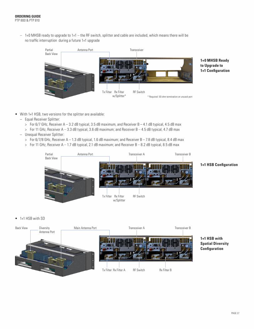
– 1+0 MHSB ready to upgrade to 1+1 – the RF switch, splitter and cable are included, which means there will be no traffic interruption during a future 1+1 upgrade
Antenna Port Transceiver
Rx Filterw/Splitter* * Required: 50 ohm termination on unused port
Tx Filter RF Switch
PartialBack View
1+0 MHSB Ready to Upgrade to 1+1 Configuration
• With 1+1 HSB, two versions for the splitter are available: – Equal Receiver Splitter: > For 6/7 GHz, Receiver A – 3.2 dB typical, 3.5 dB maximum, and Receiver B – 4.1 dB typical, 4.5 dB max > For 11 GHz, Receiver A – 3.3 dB typical, 3.6 dB maximum; and Receiver B – 4.5 dB typical, 4.7 dB max – Unequal Receiver Splitter: > For 6/7/8 GHz, Receiver A – 1.3 dB typical, 1.6 dB maximum; and Receiver B – 7.8 dB typical, 8.4 dB max > For 11 GHz, Receiver A – 1.7 dB typical, 2.1 dB maximum; and Receiver B – 8.2 dB typical, 8.5 dB max
Antenna Port Transceiver A Transceiver B
Rx Filterw/Splitter
Tx Filter RF Switch
Back View
PartialBack View
1+1 HSB Configuration
• 1+1 HSB with SD
Main Antenna Port Transceiver A Transceiver B
Rx Filter A Rx Filter BTx Filter RF Switch
Back View DiversityAntenna Port
1+1 HSB with Spatial Diversity Configuration
PAGE 28
ORDERING GUIDE PTP 800 & PTP 810
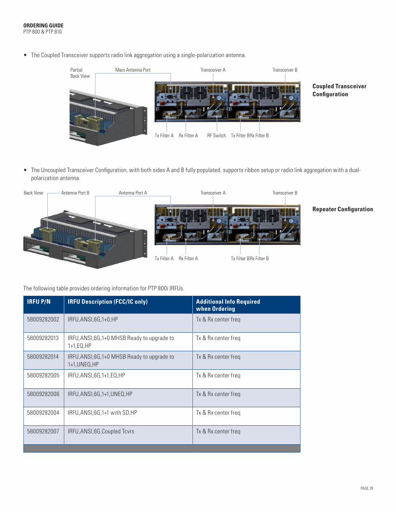
• The Coupled Transceiver supports radio link aggregation using a single-polarization antenna.
Main Antenna Port Transceiver A Transceiver B
Rx Filter ATx Filter A Rx Filter BTx Filter BRF Switch
Back View
PartialBack View
Coupled Transceiver Configuration
• The Uncoupled Transceiver Configuration, with both sides A and B fully populated, supports ribbon setup or radio link aggregation with a dual-polarization antenna.
Antenna Port A Transceiver A Transceiver B
Rx Filter ATx Filter A Rx Filter BTx Filter B
Back View Antenna Port B
Repeater Configuration
The following table provides ordering information for PTP 800i IRFUs.
IRFU P/N IRFU Description (FCC/IC only) Additional Info Required when Ordering
58009282002 IRFU,ANSI,6G,1+0,HP Tx & Rx center freq
58009282013 IRFU,ANSI,6G,1+0 MHSB Ready to upgrade to 1+1,EQ,HP
Tx & Rx center freq
58009282014 IRFU,ANSI,6G,1+0 MHSB Ready to upgrade to 1+1,UNEQ,HP
Tx & Rx center freq
58009282005 IRFU,ANSI,6G,1+1,EQ,HP Tx & Rx center freq
58009282006 IRFU,ANSI,6G,1+1,UNEQ,HP Tx & Rx center freq
58009282004 IRFU,ANSI,6G,1+1 with SD,HP Tx & Rx center freq
58009282007 IRFU,ANSI,6G,Coupled Tcvrs Tx & Rx center freq

PAGE 29
ORDERING GUIDE PTP 800 & PTP 810
IRFU P/N IRFU Description (FCC/IC only) Additional Info Required when Ordering
58009281002 IRFU,ANSI,11G,1+0,10/30MHz,HP Tx & Rx center freq
58009281019 IRFU,ANSI,11G,1+0 MHSB Ready to upgrade to 1+1,EQ,10/30MHz,HP
Tx & Rx center freq
58009281021 IRFU,ANSI,11G,1+0 MHSB Ready to upgrade to 1+1,UNEQ,10/30MHz,HP
Tx & Rx center freq
58009281004 IRFU,ANSI,11G,1+1,EQ,10/30MHz,HP Tx & Rx center freq
58009281006 IRFU,ANSI,11G,1+1,UNEQ,10/30MHz,HP Tx & Rx center freq
58009281008 IRFU,ANSI,11G,1+1 with SD,10/30MHz,HP Tx & Rx center freq
58009281010 IRFU,ANSI,11G,Coupled Tcvrs,10/30MHz,HP Tx & Rx center freq
58009281003 IRFU,ANSI,11G,1+0,40MHz,HP Tx & Rx center freq
58009281020 IRFU,ANSI,11G,1+0 MHSB Ready to upgrade to 1+1,EQ,40MHz,HP
Tx & Rx center freq
58009281022 IRFU,ANSI,11G,1+0 MHSB Ready to upgrade to 1+1,UNEQ,40MHz,HP
Tx & Rx center freq
58009281005 IRFU,ANSI,11G,1+1,EQ,40MHz,HP Tx & Rx center freq
58009281007 IRFU,ANSI,11G,1+1,UNEQ,40MHz,HP Tx & Rx center freq
58009281009 IRFU,ANSI,11G,1+1 with SD,40MHz,HP Tx & Rx center freq
58009281011 IRFU,ANSI,11G,Coupled Tcvrs,40MHz,HP Tx & Rx center freq
58009281032 IRFU,ANSI,Uncoupled Tcvrs,Side A "6G,HP" and Side B "6G,HP"
Tx & Rx center freq for both side A and B
58009281030 IRFU,ANSI,Uncoupled Tcvrs,Side A "6G,HP" and Side B "11G,10/30 MHz,HP"
Tx & Rx center freq for both side A and B
58009281031 IRFU,ANSI,Uncoupled Tcvrs,Side A "6G,HP" and Side B "11G,40 MHz,HP"
Tx & Rx center freq for both side A and B
58009281027 IRFU,ANSI,Uncoupled Tcvrs,Side A "11G,10/30 MHz,HP" and Side B "11G,10/30 MHz,HP"
Tx & Rx center freq for both side A and B
58009281028 IRFU,ANSI,Uncoupled Tcvrs,Side A "11G,10/30 MHz,HP" and Side B "11G,40 MHz,HP"
Tx & Rx center freq for both side A and B
58009281029 IRFU,ANSI,Uncoupled Tcvrs,Side A "11G,40 MHz,HP" and Side B "11G,40 MHz,HP"
Tx & Rx center freq for both side A and B

PAGE 30
ORDERING GUIDE PTP 800 & PTP 810
3.3 IRFU SPARE OPTIONS
We also offer IRFU spares for end customers.
Typically you should order a Transceiver module (XCVR) and a Fan module to provide equipment redundancy.
The front covers for spares and cable assemblies only need to be ordered when the original part is missing or damaged.Typically, you will only need a new filter when the licensed central frequency of Tx or Rx is changing, or when the IRFU needs to be re-deployed to a new location with a different frequency assignment.
PTP P/N Description
58009282001 XCVR,ANSI,6G,HP
58009281001 XCVR,ANSI,11G,HP
64009324003 FAN Assembly of IRFU
64009324001 IRFU Shelf Frontal Cover
64009324002 IRFU Shelf Frontal Extended Cover
30009399001 Cable Assembly Kit 1, SMA, M-M, R/A
30009399004 Cable Assembly Kit 2, SMA, M-M, R/A
30009399005 Cable Assembly Kit 3, SMA, M-M, R/A
30009399006 Cable Assembly Kit 4, SMA, M-M, R/A
30009399007 Cable Assembly Kit 5, SMA, M-M, R/A
30009399008 Cable Assembly Kit 6, SMA, M-M, R/A
30009399009 Cable Assembly Kit 7, SMA, M-M, R/A
30009399010 Cable Assembly Kit 8, SMA, M-M, R/A
30009399011 Cable Assembly Kit 9, SMA, M, R/A-M, R/A
30009399002 Cable Assembly Kit 10, SMA, M, R/A-M, R/A
30009399003 Cable Assembly Kit 11, SMA, M, R/A-M, R/A
91009314001 Tx Filter Assembly,6G, 10/30MHz
91009314004 Rx Filter Assembly,6G, 10/30MHz
91009314002 Tx Filter Assembly,11G, 40 MHz
91009314003 Tx Filter Assembly,11G, 10/30MHz
91009314005 Rx Filter Assembly,11G, 40 MHz
91009314006 Rx Filter Assembly,11G, 10/30MHz
PAGE 31
ORDERING GUIDE PTP 800 & PTP 810
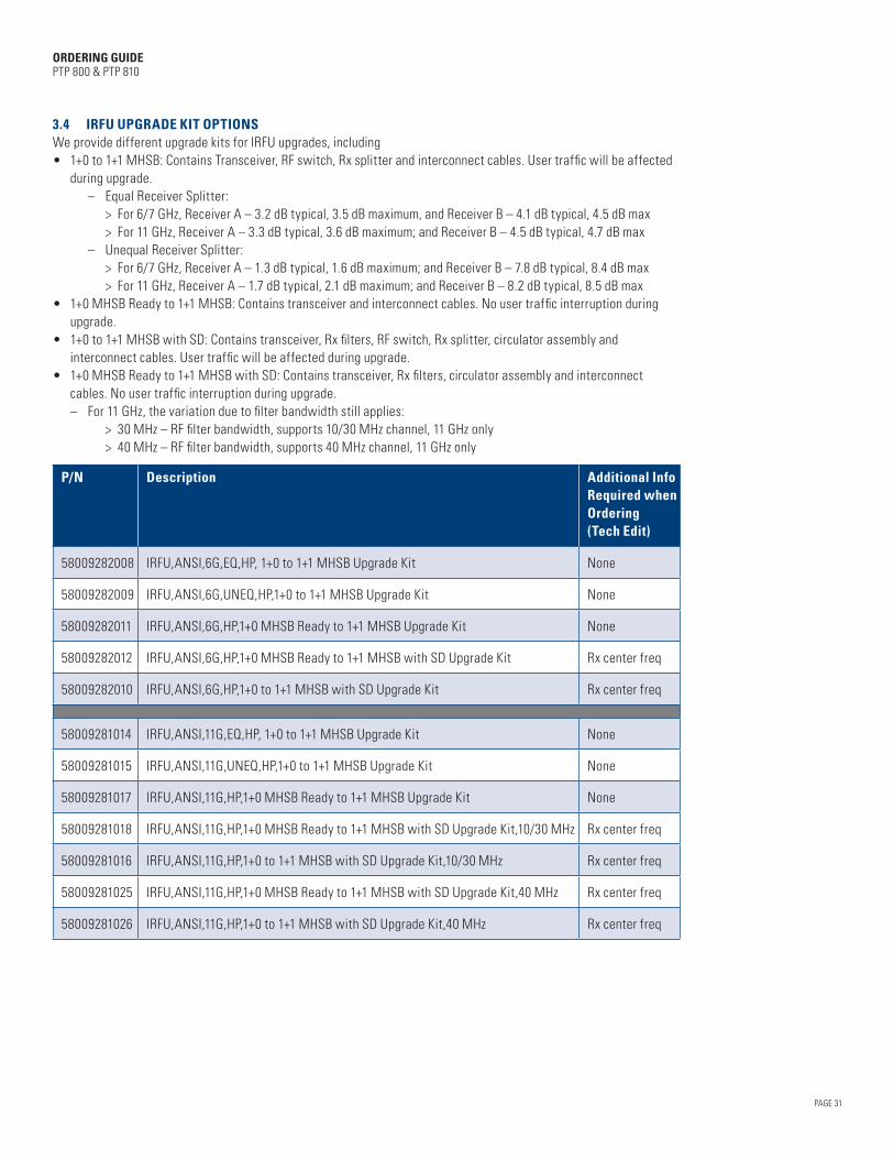
3.4 IRFU UPGRADE KIT OPTIONS We provide different upgrade kits for IRFU upgrades, including • 1+0 to 1+1 MHSB: Contains Transceiver, RF switch, Rx splitter and interconnect cables. User traffic will be affected
during upgrade. – Equal Receiver Splitter: > For 6/7 GHz, Receiver A – 3.2 dB typical, 3.5 dB maximum, and Receiver B – 4.1 dB typical, 4.5 dB max > For 11 GHz, Receiver A – 3.3 dB typical, 3.6 dB maximum; and Receiver B – 4.5 dB typical, 4.7 dB max – Unequal Receiver Splitter: > For 6/7 GHz, Receiver A – 1.3 dB typical, 1.6 dB maximum; and Receiver B – 7.8 dB typical, 8.4 dB max > For 11 GHz, Receiver A – 1.7 dB typical, 2.1 dB maximum; and Receiver B – 8.2 dB typical, 8.5 dB max• 1+0 MHSB Ready to 1+1 MHSB: Contains transceiver and interconnect cables. No user traffic interruption during
upgrade.• 1+0 to 1+1 MHSB with SD: Contains transceiver, Rx filters, RF switch, Rx splitter, circulator assembly and
interconnect cables. User traffic will be affected during upgrade.• 1+0 MHSB Ready to 1+1 MHSB with SD: Contains transceiver, Rx filters, circulator assembly and interconnect
cables. No user traffic interruption during upgrade. – For 11 GHz, the variation due to filter bandwidth still applies: > 30 MHz – RF filter bandwidth, supports 10/30 MHz channel, 11 GHz only > 40 MHz – RF filter bandwidth, supports 40 MHz channel, 11 GHz only
P/N Description Additional Info Required when Ordering (Tech Edit)
58009282008 IRFU,ANSI,6G,EQ,HP, 1+0 to 1+1 MHSB Upgrade Kit None
58009282009 IRFU,ANSI,6G,UNEQ,HP,1+0 to 1+1 MHSB Upgrade Kit None
58009282011 IRFU,ANSI,6G,HP,1+0 MHSB Ready to 1+1 MHSB Upgrade Kit None
58009282012 IRFU,ANSI,6G,HP,1+0 MHSB Ready to 1+1 MHSB with SD Upgrade Kit Rx center freq
58009282010 IRFU,ANSI,6G,HP,1+0 to 1+1 MHSB with SD Upgrade Kit Rx center freq
58009281014 IRFU,ANSI,11G,EQ,HP, 1+0 to 1+1 MHSB Upgrade Kit None
58009281015 IRFU,ANSI,11G,UNEQ,HP,1+0 to 1+1 MHSB Upgrade Kit None
58009281017 IRFU,ANSI,11G,HP,1+0 MHSB Ready to 1+1 MHSB Upgrade Kit None
58009281018 IRFU,ANSI,11G,HP,1+0 MHSB Ready to 1+1 MHSB with SD Upgrade Kit,10/30 MHz Rx center freq
58009281016 IRFU,ANSI,11G,HP,1+0 to 1+1 MHSB with SD Upgrade Kit,10/30 MHz Rx center freq
58009281025 IRFU,ANSI,11G,HP,1+0 MHSB Ready to 1+1 MHSB with SD Upgrade Kit,40 MHz Rx center freq
58009281026 IRFU,ANSI,11G,HP,1+0 to 1+1 MHSB with SD Upgrade Kit,40 MHz Rx center freq

PAGE 32
ORDERING GUIDE PTP 800 & PTP 810
4. ANTENNA & ANTENNA ACCESSORIES
We provide both single-polarization and dual-polarization antennas for PTP 800 and PTP 810 radios using the Andrew ValuLine® series (VHLP, VHLPX), HP, HPX, HSX, and PAR series.
4.1 ODU MOUNTING OPTIONSThere are two different mounting options for an ODU: direct mount and remote mount. When you plan your PTP 800 or PTP 810 link, PTP LINKPlanner gives you the opportunity to choose direct or remote mount. Then your BOM will include the appropriate equipment for your mounting option.
Direct Mount Remote Mount
Direct mount: In a direct-mount configuration, your ODU is mounted directly to the antenna using clips. It can only be supported with a customized single-polarization antenna equipped with our antenna interface.
Remote mount: When the remote-mount option is chosen, your ODU is mounted using an ODU Remote Mount Kit and connected to the antenna using a flexible waveguide. For a remote mount installation, the following flexible waveguide flanges are used:
Frequency Antenna Flange
Remote Mount Kit
Flange
Flexible Waveguide
FlangeNotes
6 GHz PDR70 UDR70 UDR70/PDR70
6 GHz CPR137G UDR70 CPR137G/PDR70
7/8 GHz PDR84 UBR84 UBR84/PBR84
11 GHz PDR100 UBR120 UBR120/PBR120 A tapered transition is required (PBR120/UDR100)
11 GHz CPR90G UBR120 CPR90G/PDR100 A tapered transition is required (PBR120/UDR100)
13 GHz PBR120 UBR120 UBR120/PBR120
15 GHz PBR140 UBR140 UBR140/PBR140
18/23/26 GHz PBR220 UBR220 UBR220/PBR220
28/32/38 GHz PBR320 UBR320 UBR320/PBR320
PAGE 33
ORDERING GUIDE PTP 800 & PTP 810
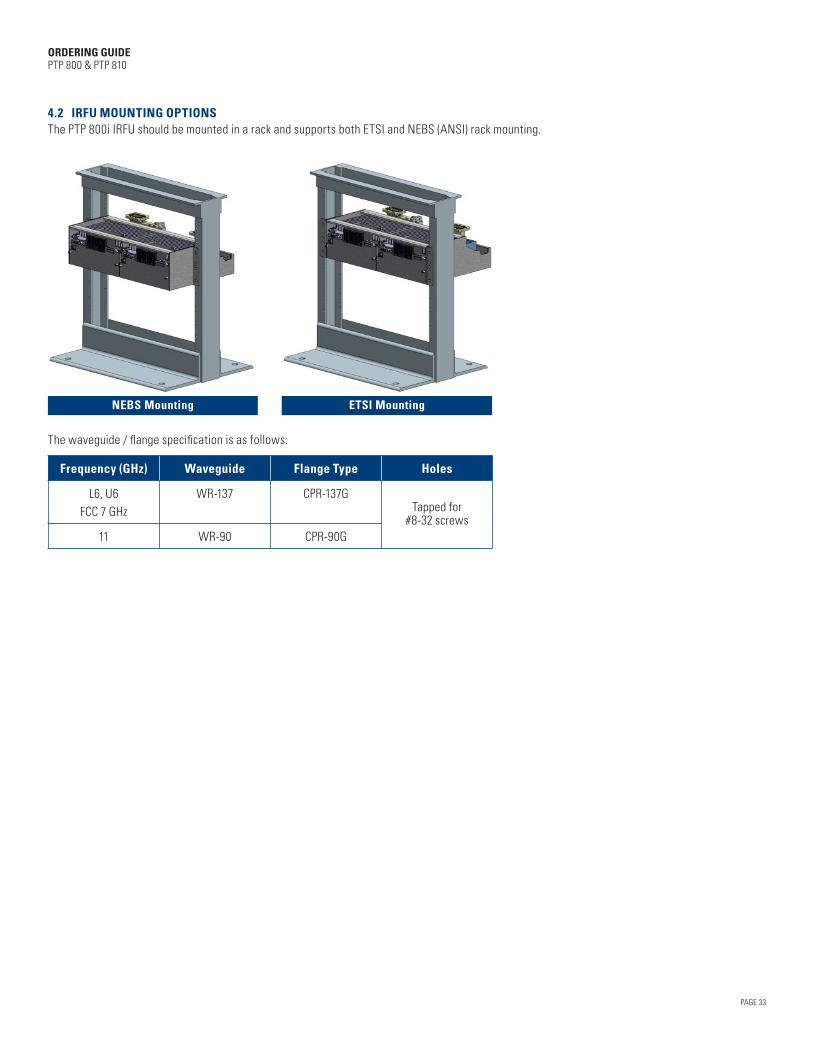
4.2 IRFU MOUNTING OPTIONSThe PTP 800i IRFU should be mounted in a rack and supports both ETSI and NEBS (ANSI) rack mounting.
NEBS Mounting ETSI Mounting
The waveguide / flange specification is as follows:
Frequency (GHz) Waveguide Flange Type Holes
L6, U6FCC 7 GHz
WR-137 CPR-137GTapped for
#8-32 screws11 WR-90 CPR-90G

4.3 ANTENNA OPTIONSFor Split-Mount deployments, we provide customized single-polarization antennas from Andrew for direct mounting to ODUs, and Andrew standard single-polarization and dual-polarization for remote mounting to ODUs. Ordering details are provided in the following tables.
PAGE 34
ORDERING GUIDE PTP 800 & PTP 810
P/N Direct-Mount, Single Polarization Antennas for ODU-A and ODU-B AntennaInterface
85009298001 3’ HP Antenna, 5.925 ~ 7.125 GHz, Single Pol, Mot Interface Mot
1 – 2.6 ft
4 – 6 ft
85010089050 4' HP Antenna, 5.925 ~ 7.125 GHz, Single Pol, Mot Interface Mot
85010089021 6' HP Antenna, 5.925 ~ 7.125 GHz, Single Pol, Mot Interface Mot
85010089045 2’ HP Antenna, 7.10 ~ 8.5 GHz, Single Pol, Mot Interface Mot
85009298002 3’ HP Antenna, 7.10 ~ 8.5 GHz, Single Pol, Mot Interface Mot
85010089051 4’ HP Antenna, 7.125 ~ 8.5 GHz, Single Pol, Mot Interface Mot
85010089025 6' HP Antenna, 7.125 ~ 8.5 GHz, Single Pol, Mot Interface Mot
85010089049 2’ HP Antenna, 10.125 ~ 11.70 GHz, Single Pol, Mot Interface Mot
85009298003 3’ HP Antenna, 10.125 ~ 11.70 GHz, Single Pol, Mot Interface Mot
85010089052 4' HP Antenna, 10.125 ~ 11.70 GHz, Single Pol, Mot Interface Mot
85010089003 2.6' HP Antenna, 10.70 ~ 11.70 GHz, Single Pol, Mot Interface Mot
85010089005 6' HP Antenna, 10.70 ~ 11.70 GHz, Single Pol, Mot Interface Mot
85010089053 1’ HP Antenna, 12.75 ~ 13.25 GHz, Single Pol, Mot Interface Mot
85010089046 2’ HP Antenna, 12.70 ~ 13.25 GHz, Single Pol, Mot Interface Mot
85009298004 3’ HP Antenna, 12.70 ~ 13.25 GHz, Single Pol, Mot Interface Mot
85010089054 4’ HP Antenna, 12.70 ~ 13.25 GHz, Single Pol, Mot Interface Mot
85010089030 6' HP Antenna, 12.75 ~ 13.25 GHz, Single Pol, Mot Interface Mot
85010089055 1' HP Antenna, 14.25 ~ 15.35 GHz, Single Pol, Mot Interface Mot
85010089056 4' HP Antenna, 14.25 ~ 15.35 GHz, Single Pol, Mot Interface Mot
85010089035 6' HP Antenna, 14.25 ~ 15.35 GHz, Single Pol, Mot Interface Mot
85010089047 2’ HP Antenna, 14.40 ~ 15.35 GHz, Single Pol, Mot Interface Mot
85009298005 3’ HP Antenna, 14.40 ~ 15.35 GHz, Single Pol, Mot Interface Mot
85010089057 1' HP Antenna, 17.70 ~ 19.70 GHz, Single Pol, Mot Interface Mot
85010089042 2’ HP Antenna, 17.70 ~ 19.70 GHz, Single Pol, Mot Interface Mot
85009298006 3’ HP Antenna, 17.70 ~ 19.70 GHz, Single Pol, Mot Interface Mot
85010089058 4' HP Antenna, 17.70 ~ 19.70 GHz, Single Pol, Mot Interface Mot
85010089010 6' HP Antenna, 17.70 ~ 19.70 GHz, Single Pol, Mot Interface Mot
85010089059 1' HP Antenna, 21.20 ~ 23.60 GHz, Single Pol, Mot Interface Mot
85010089043 2’ HP Antenna, 21.20 ~ 23.60 GHz, Single Pol, Mot Interface Mot
85009298007 3’ HP Antenna, 21.20 ~ 23.60 GHz, Single Pol, Mot Interface Mot
85010089060 4' HP Antenna, 21.20 ~ 23.60 GHz, Single Pol, Mot Interface Mot
85010089015 6' HP Antenna, 21.20 ~ 23.60 GHz, Single Pol, Mot Interface Mot

PAGE 35
ORDERING GUIDE PTP 800 & PTP 810
P/N Direct-Mount, Single Polarization Antennas for ODU-A and ODU-B AntennaInterface
85010089061 1' HP Antenna, 24.25 ~ 26.50 GHz, Single Pol, Mot Interface Mot
85010089044 2’ HP Antenna, 24.25 ~ 26.50 GHz, Single Pol, Mot Interface Mot
85009298008 3’ HP Antenna, 24.25 ~ 26.50 GHz, Single Pol, Mot Interface Mot
85010089062 4' HP Antenna, 24.25 ~ 26.50 GHz, Single Pol, Mot Interface Mot
85010089064 1' HP Antenna, 27.50 ~ 29.50 GHz, Single Pol, Mot Interface Mot
85010089041 2' HP Antenna, 27.50 ~ 29.50 GHz, Single Pol, Mot Interface Mot
85010089036 1' HP Antenna, 31.80 ~ 33.40 GHz, Single Pol, Mot Interface Mot
85010089037 2' HP Antenna, 31.80 ~ 33.40 GHz, Single Pol, Mot Interface Mot
85010089063 1' HP Antenna, 37.00 ~ 40.00 GHz, Single Pol, Mot Interface Mot
85010089048 2’ HP Antenna, 37.00 ~ 40.00 GHz, Single Pol, Mot Interface Mot
85009302001 3' HP Antenna, 5.925 ~ 7.125 GHz, Dual Pol with OMK Mot
85009302002 4' HP Antenna, 5.925 ~ 7.125 GHz, Dual Pol with OMK Mot
85009302003 6' HP Antenna, 5.925 ~ 7.125 GHz, Dual Pol with OMK Mot
85009303001 2' HP Antenna, 7.125 ~ 8.5 GHz, Dual Pol with OMK Mot
85009303002 3' HP Antenna, 7.125 ~ 8.5 GHz, Dual Pol with OMK Mot
85009303003 4' HP Antenna, 7.125 ~ 8.5 GHz, Dual Pol with OMK Mot
85009303004 6' HP Antenna, 7.125 ~ 8.5 GHz, Dual Pol with OMK Mot
85009304001 2' HP Antenna, 10.125 ~ 11.70 GHz, Dual Pol with OMK Mot
85009304002 3' HP Antenna, 10.125 ~ 11.70 GHz, Dual Pol with OMK Mot
85009304003 4' HP Antenna, 10.125 ~ 11.70 GHz, Dual Pol with OMK Mot
85009304004 6' HP Antenna, 10.125 ~ 11.70 GHz, Dual Pol with OMK Mot
85009305001 1' HP Antenna, 12.75 ~ 13.25 GHz, Dual Pol with OMK Mot
85009305002 2' HP Antenna, 12.75 ~ 13.25 GHz, Dual Pol with OMK Mot
85009305003 3' HP Antenna, 12.75 ~ 13.25 GHz, Dual Pol with OMK Mot
85009305004 4' HP Antenna, 12.75 ~ 13.25 GHz, Dual Pol with OMK Mot
85009305005 6' HP Antenna, 12.75 ~ 13.25 GHz, Dual Pol with OMK Mot
85009306001 1' HP Antenna, 14.25 ~ 15.35 GHz, Dual Pol with OMK Mot
85009306002 2' HP Antenna, 14.25 ~ 15.35 GHz, Dual Pol with OMK Mot
85009306003 3' HP Antenna, 14.40 ~ 15.35 GHz, Dual Pol with OMK Mot
85009306004 4' HP Antenna, 14.25 ~ 15.35 GHz, Dual Pol with OMK Mot
85009306005 6' HP Antenna, 14.25 ~ 15.35 GHz, Dual Pol with OMK Mot
85009307001 1' HP Antenna, 17.70 ~ 19.70 GHz, Dual Pol with OMK Mot
85009307002 2' HP Antenna, 17.70 ~ 19.70 GHz, Dual Pol with OMK Mot
85009307003 3' HP Antenna, 17.70 ~ 19.70 GHz, Dual Pol with OMK Mot
85009307004 4' HP Antenna, 17.70 ~ 19.70 GHz, Dual Pol with OMK Mot
85009307005 6' HP Antenna, 17.70 ~ 19.70 GHz, Dual Pol with OMK Mot

PAGE 36
ORDERING GUIDE PTP 800 & PTP 810
P/N Direct-Mount, Single Polarization Antennas for ODU-A and ODU-B AntennaInterface
85009308001 1' HP Antenna, 21.20 ~ 23.60 GHz, Dual Pol with OMK Mot
85009308002 2' HP Antenna, 21.20 ~ 23.60 GHz, Dual Pol with OMK Mot
85009308003 3' HP Antenna, 21.20 ~ 23.60 GHz, Dual Pol with OMK Mot
85009308004 4' HP Antenna, 21.20 ~ 23.60 GHz, Dual Pol with OMK Mot
85009308005 6' HP Antenna, 21.20 ~ 23.60 GHz, Dual Pol with OMK Mot
P/N Remote-Mount, Single and Dual Polarization Antennas for ODU-A and ODU-B
AntennaInterface
85010091022 3’ HP Antenna, 5.925 ~ 7.125 GHz, Single Pol, PDR70 PDR70
85010091024 4' HP Antenna, 5.925 ~ 7.125 GHz, Single Pol, PDR70 PDR70
85010091007 6' HP Antenna, 5.925 ~ 7.125 GHz, Single Pol, PDR70 PDR70
85009328001 HP4 - 4' SP Antenna, 5.725 ~ 6.425 GHz with radome, Single Pol, CPR137G CPR137G
85009328002 HP4 - 4' SP Antenna, 6.425 ~ 7.125 GHz with radome, Single Pol, CPR137G CPR137G
85009294001 PAR6 - 6' SP Antenna, 5.925 ~7.125 GHz with radome, Single Pol, CPR137G CPR137G
85009294002 PAR8 - 8' SP Antenna, 5.925 ~ 7.125 GHz with radome, Single Pol, CPR137G CPR137G
85009294003 PAR10 - 10' SP Antenna, 5.925 ~ 7.125 GHz w/o radome, Single Pol, CPR137G CPR137G
85009294004 PAR12 - 12' SP Antenna, 5.925 ~ 7.125 GHz w/o radome, Single Pol, CPR137G CPR137G
85009301001 HP4 – 4’ SP Antenna, 10.7 ~ 11.7 GHz with radome, Single Pol, CPR90G CPR90G
85009294005 PAR6 – 6’ SP Antenna, 10.7 ~ 11.7 GHz with radome, Single Pol, CPR90G CPR90G
85009294006 PAR8 – 8’ SP Antenna, 10.7 ~ 11.7 GHz with radome, Single Pol, CPR90G CPR90G
85009295001 10' Radome for PAR10 antenna
85009295002 12' Radome for PAR12 antenna
85010091020 2’ HP Antenna, 7.10 ~ 8.5 GHz, Single Pol, PDR84 PDR84
85010091023 3’ HP Antenna, 7.10 ~ 8.5 GHz, Single Pol, PDR84 PDR84
85010091025 4' HP Antenna, 7.125 ~ 8.5 GHz, Single Pol, PDR84 PDR84
85010091011 6' HP Antenna, 7.125 ~ 8.5 GHz, Single Pol, PDR84 PDR84
85010091019 2’ HP Antenna, 10.125 ~ 11.70 GHz, Single Pol, PDR100 PDR100
85010091017 3’ HP Antenna, 10.125 ~ 11.70 GHz, Single Pol, PDR100 PDR100
85010091026 4' HP Antenna, 10.125 ~ 11.70 GHz, Single Pol, PDR100 PDR100
85010091003 2.6' HP Antenna, 10.70 ~ 11.70 GHz, Single Pol, PDR100 PDR100
85010091005 6' HP Antenna, 10.70 ~ 11.70 GHz, Single Pol, PDR100 PDR100
85010091021 2’ HP Antenna, 12.70 ~ 13.25 GHz, Single Pol, PBR120 PBR120
85010091018 3’ HP Antenna, 12.70 ~ 13.25 GHz, Single Pol, PBR120 PBR120
85010091012 1' HP Antenna, 12.75 ~ 13.25 GHz, Single Pol, PBR120 PBR120
85010091027 4' HP Antenna, 12.75 ~ 13.25 GHz, Single Pol, PBR120 PBR120
85010091016 6' HP Antenna, 12.75 ~ 13.25 GHz, Single Pol, PBR120 PBR120

PAGE 37
ORDERING GUIDE PTP 800 & PTP 810
P/N Remote-Mount, Single and Dual Polarization Antennas for ODU-A and ODU-B
AntennaInterface
85010092048 3’ HP Antenna, 5.925 ~ 7.125 GHz, Dual Pol, PDR70 PDR70
85010092060 4' HP Antenna, 5.925 ~ 7.125 GHz, Dual Pol, PDR70 PDR70
85010092021 6' HP Antenna, 5.925 ~ 7.125 GHz, Dual Pol, PDR70 PDR70
85010092051 2’ HP Antenna, 7.10 ~ 8.5 GHz, Dual Pol, PDR84 PDR84
85010092059 3’ HP Antenna, 7.10 ~ 8.5 GHz, Dual Pol, PDR84 PDR84
85010092061 4' HP Antenna, 7.125 -8.5 GHz, Dual Pol, PDR84 PDR84
85010092025 6' HP Antenna, 7.125 -8.5 GHz, Dual Pol, PDR84 PDR84
85010092052 2’ HP Antenna, 10.125 ~ 11.70 GHz, Dual Pol, PDR100 PDR100
85010092042 3’ HP Antenna, 10.125 ~ 11.70 GHz, Dual Pol, PDR100 PDR100
85010092062 4' HP Antenna, 10.125 ~ 11.70 GHz, Dual Pol, PDR100 PDR100
85010092003 2.6' HP Antenna, 10.70 ~ 11.70 GHz, Dual Pol , PDR100 PDR100
85010092005 6' HP Antenna, 10.70 ~ 11.70 GHz, Dual Pol, PDR100 PDR100
85010092056 2’ HP Antenna, 12.70 ~ 13.25 GHz, Dual Pol, PBR120 PBR120
85010092043 3’ HP Antenna, 12.70 ~ 13.25 GHz, Dual Pol, PBR120 PBR120
85010092026 1' HP Antenna, 12.75 ~ 13.25 GHz, Dual Pol, PBR120 PBR120
85010092063 4' HP Antenna, 12.75 ~ 13.25 GHz, Dual Pol, PBR120 PBR120
85010092030 6' HP Antenna, 12.75 ~ 13.25 GHz, Dual Pol, PBR120 PBR120
85010092031 1' HP Antenna, 14.25 ~ 15.35 GHz, Dual Pol, PBR140 PBR140
85010092064 4' HP Antenna, 14.25 ~ 15.35 GHz, Dual Pol, PBR140 PBR140
85010092035 6' HP Antenna, 14.25 ~ 15.35 GHz, Dual Pol, PBR140 PBR140
85010092057 2’ HP Antenna, 14.40 ~ 15.35 GHz, Dual Pol, PBR140 PBR140
85010092044 3’ HP Antenna, 14.40 ~ 15.35 GHz, Dual Pol, PBR140 PBR140
85010092006 1' HP Antenna, 17.70 ~ 19.70 GHz, Dual Pol, PBR220 PBR220
85010092053 2’ HP Antenna, 17.70 ~ 19.70 GHz, Dual Pol, PBR220 PBR220
85010092045 3’ HP Antenna, 17.70 ~ 19.70 GHz, Dual Pol, PBR220 PBR220
85010092065 4' HP Antenna, 17.70 ~ 19.70 GHz, Dual Pol, PBR220 PBR220
85010092010 6' HP Antenna, 17.70 ~ 19.70 GHz, Dual Pol, PBR220 PBR220
85010092011 1' HP Antenna, 21.20 ~ 23.60 GHz, Dual Pol, PBR220 PBR220
85010092054 2’ HP Antenna, 21.20 ~ 23.60 GHz, Dual Pol, PBR220 PBR220
85010092046 3’ HP Antenna, 21.20 ~ 23.60 GHz, Dual Pol, PBR220 PBR220
85010092066 4' HP Antenna, 21.20 ~ 23.60 GHz, Dual Pol, PBR220 PBR220
85010092015 6' HP Antenna, 21.20 ~ 23.60 GHz, Dual Pol, PBR220 PBR220
85010092016 1' HP Antenna, 24.25 ~ 26.50 GHz, Dual Pol, PBR220 PBR220
85010092055 2’ HP Antenna, 24.25 ~ 26.50 GHz, Dual Pol, PBR220 PBR220
85010092047 3’ HP Antenna, 24.25 ~ 26.50 GHz, Dual Pol, PBR220 PBR220
85010092067 4' HP Antenna, 24.25 ~ 26.50 GHz, Dual Pol, PBR220 PBR220

PAGE 38
ORDERING GUIDE PTP 800 & PTP 810
P/N Remote-Mount, Single and Dual Polarization Antennas for ODU-A and ODU-B
AntennaInterface
85010092040 1' HP Antenna, 27.50 ~ 29.50 GHz, Dual Pol, PBR320 PBR320
85010092041 2' HP Antenna, 27.50 ~ 29.50 GHz, Dual Pol, PBR320 PBR320
85010092036 1' HP Antenna, 31.80 ~ 33.40 GHz, Dual Pol, PBR320 PBR320
85010092037 2' HP Antenna, 31.80 ~ 33.40 GHz, Dual Pol, PBR320 PBR320
85010092038 1' HP Antenna, 37.00 ~ 40.00 GHz, Dual Pol, PBR320 PBR320
85010092058 2' HP Antenna, 37.00 ~ 40.00 GHz, Dual Pol, PBR320 PBR320
P/N Antennas for PTP 800i and PTP 810i All-Indoor Deployments AntennaInterface
85009328001 HP4 - 4' SP Antenna, 5.725 ~ 6.425 GHz with radome, Single Pol, CPR137G (Spatial Diversity Receive Only)
CPR137G
85009328002 HP4 - 4' SP Antenna, 6.425 ~ 7.125 GHz with radome, Single Pol, CPR137G (Spatial Diversity Receive Only)
CPR137G
85009294001 PAR6 - 6' SP Antenna, 5.925 ~7.125 GHz with radome, Single Pol, CPR137G CPR137G
85009294002 PAR8 - 8' SP Antenna, 5.925 ~ 7.125 GHz with radome, Single Pol, CPR137G CPR137G
85009294003 PAR10 - 10' SP Antenna, 5.925 ~ 7.125 GHz w/o radome, Single Pol, CPR137G CPR137G
85009294004 PAR12 - 12' SP Antenna, 5.925 ~ 7.125 GHz w/o radome, Single Pol, CPR137G CPR137G
N060080L001A HSX4 – 4’ HP Antenna, 5.925 ~ 6.425 GHz with radome, Dual Pol, CPR137G CPR137G
N060080L002A HPX6 – 6’ HP Antenna, 5.925 ~ 6.425 GHz with radome, Dual Pol, CPR137G CPR137G
N060080L003A HPX8 – 8’ HP Antenna, 5.925 ~ 6.425 GHz with radome, Dual Pol, CPR137G CPR137G
N060080L004A HPX10 – 10’ HP Antenna, 5.925 ~ 6.425 GHz with radome, Dual Pol, CP 137G CPR137G
N060080L005A HPX12 – 12’ HP Antenna, 5.925 ~ 6.425 GHz with radome, Dual Pol, CPR137G CPR137G
TBD HPX4 – 4’ HP Antenna, 6.425 ~ 7.125 GHz with radome, Dual Pol, CPR137G CPR137G
N060080L006A HPX6 – 6’ HP Antenna, 6.425 ~ 7.125 GHz with radome, Dual Pol, CPR137G CPR137G
N060080L007A HPX8 – 8’ HP Antenna, 6.425 ~ 7.125 GHz with radome, Dual Pol, CPR137G CPR137G
N060080L008A HPX10 – 10’ HP Antenna, 6.425 ~ 7.125 GHz with radome, Dual Pol, CPR137G CPR137G
N060080L009A HPX12 – 12’ HP Antenna, 6.425 ~ 7.125 GHz with radome, Dual Pol, CPR137G CPR137G
85009301001 HP4 – 4’ SP Antenna, 10.7 ~ 11.7 GHz with radome, Single Pol, CPR90G CPR90G
85009294005 PAR6 – 6’ SP Antenna, 10.7 ~ 11.7 GHz with radome, Single Pol, CPR90G CPR90G
85009294006 PAR8 – 8’ SP Antenna, 10.7 ~ 11.7 GHz with radome, Single Pol, CPR90G CPR90G
N110080L001A HPX4 – 4’ HP Antenna, 10.7 ~ 11.7 GHz with radome, Dual Pol, CPR90G CPR90G
N110080L002A HPX6 – 6’ HP Antenna, 10.7 ~ 11.7 GHz with radome, Dual Pol, CPR90G CPR90G
N110080L003A HPX8 – 8’ HP Antenna, 10.7 ~ 11.7 GHz with radome, Dual Pol, CPR90G CPR90G
85009295001 10' Radome for PAR10 antenna
85009295002 12' Radome for PAR12 antenna
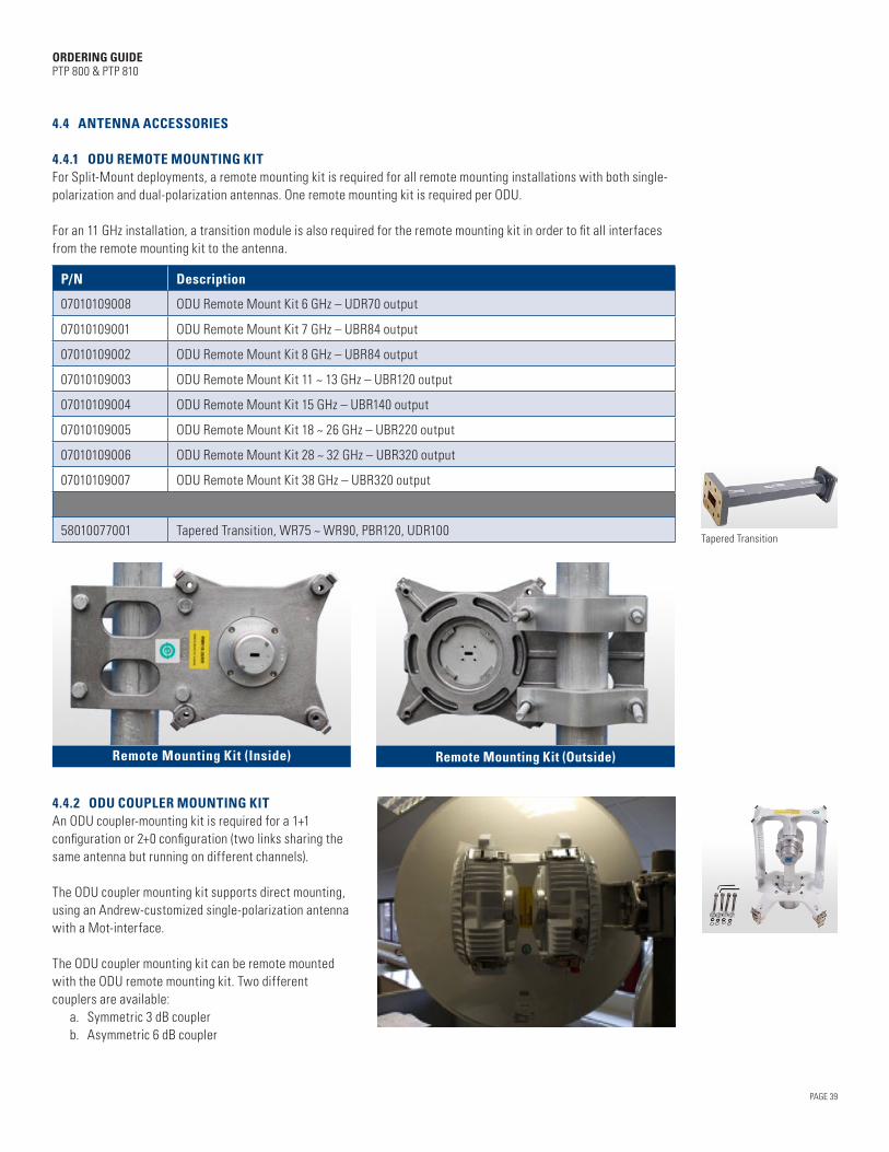
PAGE 39
ORDERING GUIDE PTP 800 & PTP 810
4.4 ANTENNA ACCESSORIES
4.4.1 ODU REMOTE MOUNTING KITFor Split-Mount deployments, a remote mounting kit is required for all remote mounting installations with both single-polarization and dual-polarization antennas. One remote mounting kit is required per ODU.
For an 11 GHz installation, a transition module is also required for the remote mounting kit in order to fit all interfaces from the remote mounting kit to the antenna.
P/N Description
Tapered Transition
07010109008 ODU Remote Mount Kit 6 GHz – UDR70 output
07010109001 ODU Remote Mount Kit 7 GHz – UBR84 output
07010109002 ODU Remote Mount Kit 8 GHz – UBR84 output
07010109003 ODU Remote Mount Kit 11 ~ 13 GHz – UBR120 output
07010109004 ODU Remote Mount Kit 15 GHz – UBR140 output
07010109005 ODU Remote Mount Kit 18 ~ 26 GHz – UBR220 output
07010109006 ODU Remote Mount Kit 28 ~ 32 GHz – UBR320 output
07010109007 ODU Remote Mount Kit 38 GHz – UBR320 output
58010077001 Tapered Transition, WR75 ~ WR90, PBR120, UDR100
Remote Mounting Kit (Inside) Remote Mounting Kit (Outside)
4.4.2 ODU COUPLER MOUNTING KITAn ODU coupler-mounting kit is required for a 1+1 configuration or 2+0 configuration (two links sharing the same antenna but running on different channels).
The ODU coupler mounting kit supports direct mounting, using an Andrew-customized single-polarization antenna with a Mot-interface.
The ODU coupler mounting kit can be remote mounted with the ODU remote mounting kit. Two different couplers are available: a. Symmetric 3 dB coupler b. Asymmetric 6 dB coupler
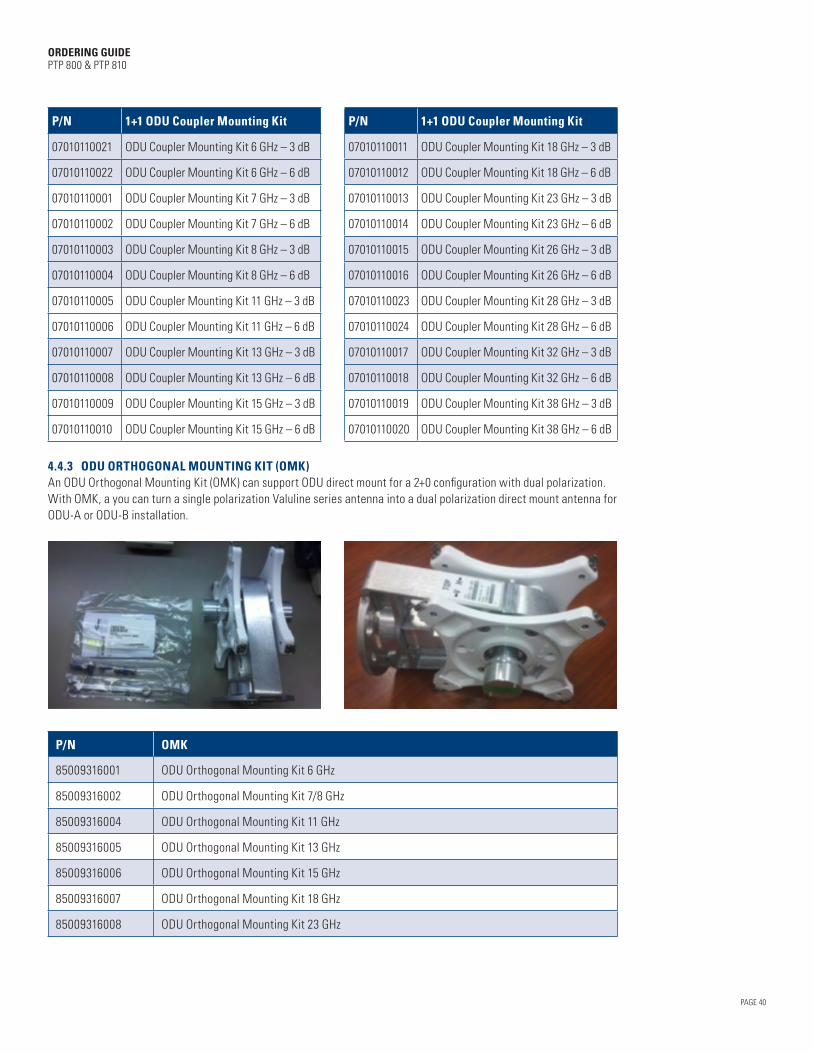
PAGE 40
ORDERING GUIDE PTP 800 & PTP 810
P/N 1+1 ODU Coupler Mounting Kit P/N 1+1 ODU Coupler Mounting Kit
07010110021 ODU Coupler Mounting Kit 6 GHz – 3 dB 07010110011 ODU Coupler Mounting Kit 18 GHz – 3 dB
07010110022 ODU Coupler Mounting Kit 6 GHz – 6 dB 07010110012 ODU Coupler Mounting Kit 18 GHz – 6 dB
07010110001 ODU Coupler Mounting Kit 7 GHz – 3 dB 07010110013 ODU Coupler Mounting Kit 23 GHz – 3 dB
07010110002 ODU Coupler Mounting Kit 7 GHz – 6 dB 07010110014 ODU Coupler Mounting Kit 23 GHz – 6 dB
07010110003 ODU Coupler Mounting Kit 8 GHz – 3 dB 07010110015 ODU Coupler Mounting Kit 26 GHz – 3 dB
07010110004 ODU Coupler Mounting Kit 8 GHz – 6 dB 07010110016 ODU Coupler Mounting Kit 26 GHz – 6 dB
07010110005 ODU Coupler Mounting Kit 11 GHz – 3 dB 07010110023 ODU Coupler Mounting Kit 28 GHz – 3 dB
07010110006 ODU Coupler Mounting Kit 11 GHz – 6 dB 07010110024 ODU Coupler Mounting Kit 28 GHz – 6 dB
07010110007 ODU Coupler Mounting Kit 13 GHz – 3 dB 07010110017 ODU Coupler Mounting Kit 32 GHz – 3 dB
07010110008 ODU Coupler Mounting Kit 13 GHz – 6 dB 07010110018 ODU Coupler Mounting Kit 32 GHz – 6 dB
07010110009 ODU Coupler Mounting Kit 15 GHz – 3 dB 07010110019 ODU Coupler Mounting Kit 38 GHz – 3 dB
07010110010 ODU Coupler Mounting Kit 15 GHz – 6 dB 07010110020 ODU Coupler Mounting Kit 38 GHz – 6 dB
4.4.3 ODU ORTHOGONAL MOUNTING KIT (OMK)An ODU Orthogonal Mounting Kit (OMK) can support ODU direct mount for a 2+0 configuration with dual polarization. With OMK, a you can turn a single polarization Valuline series antenna into a dual polarization direct mount antenna for ODU-A or ODU-B installation.
P/N OMK
85009316001 ODU Orthogonal Mounting Kit 6 GHz
85009316002 ODU Orthogonal Mounting Kit 7/8 GHz
85009316004 ODU Orthogonal Mounting Kit 11 GHz
85009316005 ODU Orthogonal Mounting Kit 13 GHz
85009316006 ODU Orthogonal Mounting Kit 15 GHz
85009316007 ODU Orthogonal Mounting Kit 18 GHz
85009316008 ODU Orthogonal Mounting Kit 23 GHz

PAGE 41
ORDERING GUIDE PTP 800 & PTP 810
4.4.4 FLEX WAVEGUIDE FOR ODU REMOTE MOUNTINGA flexible waveguide is required for the ODU remote-mounting configuration. One flex waveguide is required per remote mounting kit. The flexible waveguide is available in a 3-foot length. During installation, two hangers are recommended per flexible waveguide.
P/N Flexible Wave Guide
Flexible waveguide
58010076016 Flexible Twist,WR137,PDR70, 35.0 inch, CPR137G, 5.85~8.2 GHz, VSWR 1.10
58010076017 Flexible Twist,WR137,PDR70, 35.0 inch, UDR70, 5.85~8.2 GHz, VSWR 1.10
58010076019 Flexible Twist,WR112,PBR84, 35.0 inch, UDR84, 7.05~10.0 GHz, VSWR 1.10
58010076005 Flexible Twist,WR75,PBR120, 35.0 inch, UBR120, 10.0~15.0 GHz, VSWR 1.10
58010076018 Flexible Twist,WR90,PDR100, 35.0 inch, CPR90G, 8.2~12.4 GHz, VSWR 1.10
58010076008 Flexible Twist,WR62,PBR140, 35.0 inch, UBR140, 12.4~18.0 GHz, VSWR 1.10
58010076011 Flexible Twist,WR42,PBR220, 35.0 inch, UBR220, 17.7~26.5 GHz, VSWR 1.25
58010076014 Flexible Twist,WR28,PBR320, 35.0 inch, UBR320, 26.5~40.1 GHz, VSWR 1.30
P/N Flexible Twist Hanger Kit
Hanger
07010118001 WR137 Flex Twist Hanger Kit
N000080L001A WR90 Flex Twist Hanger Kit
07010118002 WR112 Flex Twist Hanger Kit
07010118003 WR75 Flex Twist Hanger Kit
07010118004 WR62 Flex Twist Hanger Kit
07010118005 WR42 Flex Twist Hanger Kit
07010118006 WR28 Flex Twist Hanger Kit
4.4.5 ALL-INDOOR DEPLOYMENT RELATED MATERIALSFor PTP 800i and PTP 810i All-Indoor deployments, a Premium Elliptical waveguide is required together with some accessories, including connectors, grounding kit, and pressure windows.
P/N Premium Elliptical Waveguide
58009273001 EWP52 - Premium Elliptical Waveguide, 5.725 - 6.425 GHz (per ft)
58009273003 EWP63 - Premium Elliptical Waveguide, 6.425 - 7.125 GHz (per ft)
58009273002 EWP90 - Premium Elliptical Waveguide, 10.7 - 11.7 GHz (per ft)
P/N Elliptical Waveguide Connectors
09009399001 Fixed-tuned CPR137G connector for EWP52
09009399003 Fixed-tuned CPR137G connector for EWP63
09009399002 Fixed-tuned CPR90G connector for EWP90
P/N Elliptical Waveguide Grounding Kits
07009343002 Grounding Kit for waveguide EWP90
07009343001 Grounding Kit for waveguide EWP52 and EWP63

PAGE 42
ORDERING GUIDE PTP 800 & PTP 810
P/N Elliptical Waveguide Hoisting Grips
07009344001 Hoisting Grip for waveguide EWP52 and EWP63
07009344002 Hoisting Grip for waveguide EWP90
P/N Elliptical Waveguide Pressure Windows
58009283001 Pressure Window for WR137, 5.85-8.2 GHz, mates to CPR137G
58009283002 Pressure Window for WR90, 8.2-12.4 GHz, mates to CPR90G
P/N Elliptical Waveguide Dehydrator and Gas Distribution Manifolds
01009504002 DryLine Dehydrator, Low-pressure membrane, Wall Mountable, 115 Vac
58009284001 2-port Gas Distribution Manifold
58009284002 4-port Gas Distribution Manifold
P/N Flexible Waveguides for IRFU Installation
58009279001 Flexible Twist,WR90,CPR90G,12.0 inch,CPR90G,8.2 ~ 12.4 GHz, VSWR 1.10
58009279002 Flexible Twist,WR90,CPR90G,24.0 inch,CPR90G,8.2 ~ 12.4 GHz, VSWR 1.10
58009279003 Flexible Twist,WR90,CPR90G,35.0 inch,CPR90G,8.2 ~ 12.4 GHz, VSWR 1.10
58009280001 Flexible Twist,WR137,CPR137G,12.0 inch,CPR137G,5.85 ~ 8.2 GHz, VSWR 1.10
58009280002 Flexible Twist,WR137, CPR137G,24.0 inch,CPR137G,5.85 ~ 8.2 GHz, VSWR 1.10
58009280003 Flexible Twist,WR137, CPR137G,35.0 inch,CPR137G,5.85 ~ 8.2 GHz, VSWR 1.10
P/N Flexible Waveguides for ODU-A All-Indoor Installation
30009404001 Flexible Twist,WR137,PDR70,12.0 inch, CPR137G,5.725 ~ 6.425 GHz, VSWR 1.03
30009404002 Flexible Twist,WR137,PDR70,24.0 inch, CPR137G,5.725 ~ 6.425 GHz, VSWR 1.03
30009404003 Flexible Twist,WR137,PDR70,35.0 inch, CPR137G,5.725 ~ 6.425 GHz, VSWR 1.03
30009404004 Flexible Twist,WR137,PDR70,12.0 inch, CPR137G,6.425 ~ 7.125 GHz, VSWR 1.03
30009404005 Flexible Twist,WR137,PDR70,24.0 inch, CPR137G,6.425 ~ 7.125 GHz, VSWR 1.03
30009404006 Flexible Twist,WR137,PDR70,35.0 inch, CPR137G,6.425 ~ 7.125 GHz, VSWR 1.03
67009255001 Flange Hardware Kit, PDR70
30009407001 Flexible Twist,WR90,PDR100,12.0 inch, CPR90G,10.7 ~ 11.7 GHz,VSWR 1.03
30009407002 Flexible Twist,WR90,PDR100,24.0 inch, CPR90G,10.7 ~ 11.7 GHz,VSWR 1.03
30009407003 Flexible Twist,WR90,PDR100,35.0 inch, CPR90G,10.7 ~ 11.7 GHz,VSWR 1.03
67009255002 Flange Hardware Kit, PDR 100
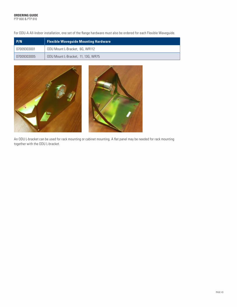
PAGE 43
ORDERING GUIDE PTP 800 & PTP 810
For ODU-A All-Indoor installation, one set of the flange hardware must also be ordered for each Flexible Waveguide.
P/N Flexible Waveguide Mounting Hardware
07009303001 ODU Mount L-Bracket, 6G, WR112
07009303005 ODU Mount L-Bracket, 11, 13G, WR75
An ODU L-bracket can be used for rack mounting or cabinet mounting. A flat panel may be needed for rack mounting together with the ODU L-bracket.
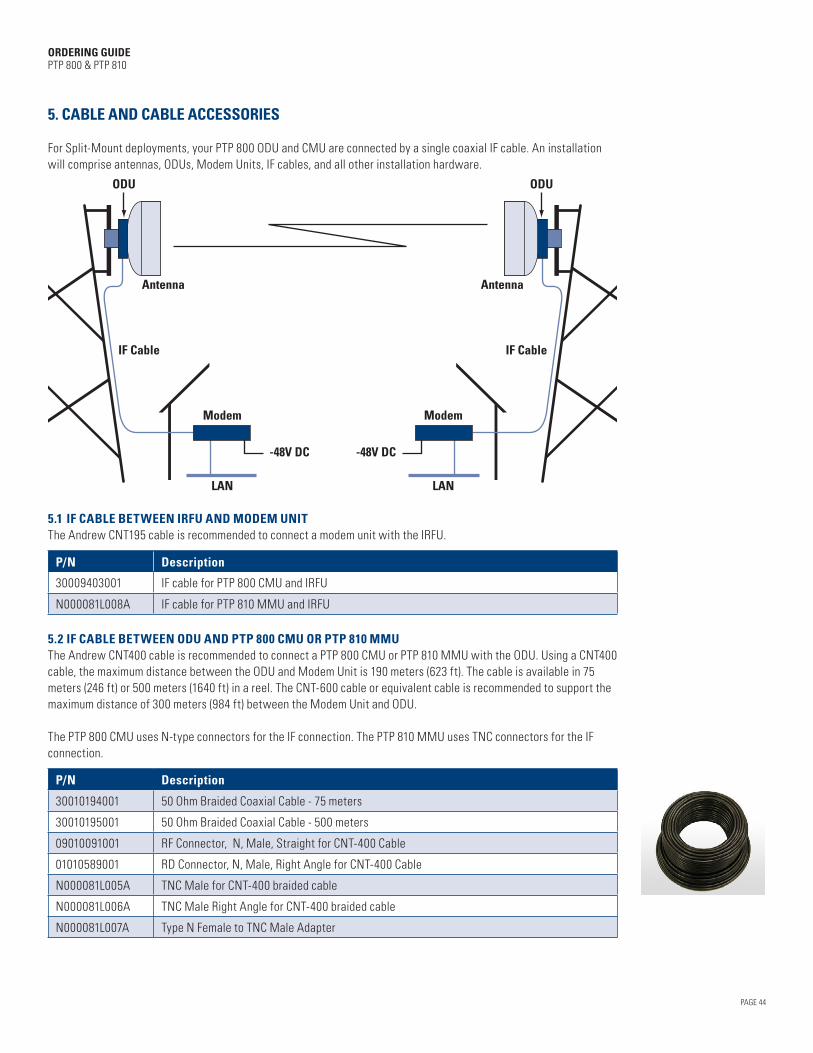
PAGE 44
ORDERING GUIDE PTP 800 & PTP 810
5. CABLE AND CABLE ACCESSORIES
For Split-Mount deployments, your PTP 800 ODU and CMU are connected by a single coaxial IF cable. An installation will comprise antennas, ODUs, Modem Units, IF cables, and all other installation hardware.
ODU
Antenna
IF Cable
Modem
LAN
-48V DC
ODU
Antenna
IF Cable
Modem
LAN
-48V DC
5.1 IF CABLE BETWEEN IRFU AND MODEM UNITThe Andrew CNT195 cable is recommended to connect a modem unit with the IRFU.
P/N Description
30009403001 IF cable for PTP 800 CMU and IRFU
N000081L008A IF cable for PTP 810 MMU and IRFU
5.2 IF CABLE BETWEEN ODU AND PTP 800 CMU OR PTP 810 MMUThe Andrew CNT400 cable is recommended to connect a PTP 800 CMU or PTP 810 MMU with the ODU. Using a CNT400 cable, the maximum distance between the ODU and Modem Unit is 190 meters (623 ft). The cable is available in 75 meters (246 ft) or 500 meters (1640 ft) in a reel. The CNT-600 cable or equivalent cable is recommended to support the maximum distance of 300 meters (984 ft) between the Modem Unit and ODU.
The PTP 800 CMU uses N-type connectors for the IF connection. The PTP 810 MMU uses TNC connectors for the IF connection.
P/N Description
30010194001 50 Ohm Braided Coaxial Cable - 75 meters
30010195001 50 Ohm Braided Coaxial Cable - 500 meters
09010091001 RF Connector, N, Male, Straight for CNT-400 Cable
01010589001 RD Connector, N, Male, Right Angle for CNT-400 Cable
N000081L005A TNC Male for CNT-400 braided cable
N000081L006A TNC Male Right Angle for CNT-400 braided cable
N000081L007A Type N Female to TNC Male Adapter

PAGE 45
ORDERING GUIDE PTP 800 & PTP 810
5.3 CABLE ASSEMBLY KITOne cable assembly kit is required per IF drop cable installation. The kit can be used for both PTP 800 and PTP 810 installations.
For a PTP 810, one TNC connector needs to be purchased together with one Cable Assembly kit because the PTP 810’s IF port requires a TNC connector.
P/N Description
WB3616H Coaxial Cable Installation Assembly Kit (w/o LPU)
The cable assembly kit includes:
Component Description Quantity Notes
1 ODU ground cable 1 0.8 m, with an M5 lug eye on both ends
2 LPU grounding cable 2 0.6 m, with an M5 and M10 lug eye on each side
3 ODU to LPU cable 1 0.7 m jumper cable with N-type connector
4 Cable grounding kit 2 One cable grounding kit provided for the bottom of the tower and one at the entry to the building. Same as P/N: 01010419001
5 N-type connectors for the drop cable
4 Two connectors provided for the drop cable and two for the bottom SPD to CMU cable.
6 Vinyl insulating tape, 19mm (¾ inch) 1 0.19 m
7 Vinyl insulating tape, 51mm (2 inch) 1 0.51 m
8 Self-amalgamating tape 1 3.0 m
9 Tie wraps 50
10 Instruction sheet 1
11 Packing List 1
5.4 LIGHTNING PROTECTION KITOne lightning protection kit is required per IF drop cable installation. The kit includes two surge protection units and one mounting kit. The kit can be used for both PTP 800 and PTP 810 installations.
P/N Description
WB3657A LPU END KIT PTP 800 (1 kit required per coaxial cable)
The Polyphaser BGXZ series Lightning Protection Unit (LPU) is recommended for your PTP 800 or PTP 810 installation. The lightning protection kit includes:
Component Description Qty Notes
1 BGXZ Surge protection unit 2 From Polyphaser
2 Mounting kit for surge protection unit 1

PAGE 46
ORDERING GUIDE PTP 800 & PTP 810
5.5 CABLE GROUNDING KITThe Andrew 223158-2 cable grounding kit is recommended. Two cable grounding kits are already included in the cable assembly kit (see details in Section 4.2). The kit can be used for both PTP 800 and PTP 810 installations. The following kits are available for extra cable grounding:
P/N Description
01010419001 Cable Grounding Kits for 1/4" and 3/8" cable
5.6 PTP 810 MMU CONSOLE PORT ADAPTERThe PTP 810 MMU supports local access using both Ethernet and a serial port connection for management. For customers who like to use a serial port, a console port adapter or customer-made cable is required (for Pin Diagram, see the PTP 810 User Manual).
Cambium Networks provides the following console port adapter:
P/N Description
N000081L003A PTP810 MMU Console Port Connector Adapter
5.7 CRIMP TOOLA crimp tool is required to make the N-type connectors for the IF cable.
P/N Description
66010063001 Crimp tool for N-type connector
5.8 HOISTING GRIP FOR CNT-400 CABLEThe hoisting grip tool can be used only one time and cannot be reused. The kit can be used for both PTP 800 and PTP 810 installations.
P/N Description
07009304001 Hoisting Grip for CNT-400 cable
6. SOFTWARE
You do not need to order software separately. The radios are shipped pre-loaded with operational software. The latest software can be downloaded from PTP software.
For out-of-warranty products, you need to purchase a software support contract in order to get the latest software.
P/N Description
WB3106A 1 Year PTP Software Support Contract (1-2 Links)
WB3107A 1 Year PTP Software Support Contract (3-5 Links)
WB3108A 1 Year PTP Software Support Contract (6+ Links)
PAGE 47
ORDERING GUIDE PTP 800 & PTP 810
7. WARRANTY AND SERVICES
7.1 STANDARD WARRANTY With your purchase of a PTP 800 or 810 link, we provide a 12-month limited warranty on hardware components. Your standard warranty includes return-and-repair terms for damaged parts, plus minor software enhancements as available and 24x7 telephone support. Damaged units are shipped to our Repair Center where the units are repaired and returned within 30 calendar days.
In addition, two Extended Warranty3 options are available. .
7.2 EXTENDED WARRANTY WITH ALL RISKS ADVANCED REPLACEMENT4 This warranty upgrades and/or extends the initial 12-month Standard Warranty to include All Risks equipment coverage with our Advanced Replacement program. The All Risks feature provides coverage for virtually all types of equipment damage, including lightning, dropped units, vandalism, fire and other types of damage. Under the Advanced Replacement program, replacement units are shipped from a Cambium repair center5 the next business day after receipt of the returned product under a confirmed RMA. We pay shipping costs in both directions. Delivery times will depend on ship-to location and customs. This warranty also includes minor software enhancements as they become available and 24x7 telephone support.
P/N Description
WB3560 PTP 800 Upgrade to All Risks Advanced Replacement Program During 1st Year Warranty
WB3561 PTP 800 Extended Warranty & All Risks Advanced Replacement Program, 1 Additional Yr
WB3562 PTP 800 Extended Warranty & All Risks Advanced Replacement Program, 2 Additional Yrs
WB3563 PTP 800 Extended Warranty & All Risks Advanced Replacement Program, 4 Additional Yrs
WB3922 PTP 800 ODU-A or ODU-B (End Only) Upgrade to All Risks Advanced Replacement Program During 1st Year Warranty
WB3923 PTP 800 ODU-A or ODU-B (End Only) Extended Warranty & All Risks Advanced Replacement Program, 1 Additional Yr
WB3924 PTP 800 ODU-A or ODU-B (End Only) Extended Warranty & All Risks Advanced Replacement Program, 2 Additional Yrs
WB3925 PTP 800 ODU-A or ODU-B (End Only) Extended Warranty & All Risks Advanced Replacement Program, 4 Additional Yrs
WB3929 PTP 800 CMU (End Only) Upgrade to All Risks Advanced Replacement Program During 1st Year Warranty
WB3930 PTP 800 CMU (End Only) Extended Warranty & All Risks Advanced Replacement Program, 1 Additional Yr
WB3931 PTP 800 CMU (End Only) Extended Warranty & All Risks Advanced Replacement Program, 2 Additional Yrs
WB3932 PTP 800 CMU (End Only) Extended Warranty & All Risks Advanced Replacement Program, 4 Additional Yrs
N000081S007A PTP 810 MMU Upgrade to All Risks Advanced Replacement Program during 1st Year warranty
N000081S001A PTP 810 MMU Extended Warranty & All Risks Advanced Replacement Program, 1 Additional Yr
N000081S002A PTP 810 MMU Extended Warranty & All Risks Advanced Replacement Program, 2 Additional Yrs
N000081S003A PTP 810 MMU Extended Warranty & All Risks Advanced Replacement Program, 4 Additional Yrs
WB4244 IRFU XVCR & FAN (End Only) All Risks Advanced Replacement Program during 1st Year warranty
WB4245 IRFU XVCR & FAN (End Only) All Risks Advanced Replacement Program, 1 Additional Yr
WB4246 IRFU XVCR & FAN (End Only) All Risks Advanced Replacement Program, 2 Additional Yrs
WB4247 IRFU XVCR & FAN (End Only) All Risks Advanced Replacement Program, 4 Additional Yrs
3 Extended warranties are not offered on 1+1 hot standby kits, antennas, antenna accessories or mounting kits.
4 PTP 800 and PTP 810 All Risks Advanced Replacement Extended Warranties may not be available in all geographic regions. No advanced replacement warranties are offered on 1+1 hot standby kits, antennas, antenna accessories or mounting kits.
5 Based on your location, PTP 800 and PTP 810 equipment may ship from a location other than the UK.

PAGE 48
ORDERING GUIDE PTP 800 & PTP 810
7.3 EXTENDED WARRANTY WITH RETURN-AND-REPAIR This warranty extends the initial 12-month Standard Warranty with 30-day return-and-repair terms through the second, third or fifth years of ownership. The warranty also includes minor software enhancements as they become available and 24 x 7 telephone support. Typically, you would choose this option when one or more spare units are purchased for use as replacement units.
P/N Description
WB3557 PTP 800 Extended Warranty, 1 Additional Yr
WB3558 PTP 800 Extended Warranty, 2 Additional Yrs
WB3559 PTP 800 Extended Warranty, 4 Additional Yrs
WB3919 PTP 800 ODU-A or ODU-B (End Only) Extended Warranty, 1 Additional Yr
WB3920 PTP 800 ODU-A or ODU-B (End Only) Extended Warranty, 2 Additional Yrs
WB3921 PTP 800 ODU-A or ODU-B (End Only) Extended Warranty, 4 Additional Yrs
WB3926 PTP 800 CMU (End Only) Extended Warranty, 1 Additional Yr
WB3927 PTP 800 CMU (End Only) Extended Warranty, 2 Additional Yrs
WB3928 PTP 800 CMU (End Only) Extended Warranty, 4 Additional Yrs
WB4189 IRFU w/ one XVCR (End Only) Extended Warranty, 1 Additional Yr
WB4190 IRFU w/ one XVCR (End Only) Extended Warranty, 2 Additional Yrs
WB4191 IRFU w/ one XVCR (End Only) Extended Warranty, 4 Additional Yrs
N000081S004A PTP 810 MMU Extended Warranty, 1 Additional Yr
N000081S005A PTP 810 MMU Extended Warranty, 2 Additional Yrs
N000081S006A PTP 810 MMU Extended Warranty, 4 Additional Yrs
7.4 FCC MICROWAVE LICENSE COORDINATION SERVICES For customers in the United States, we offer FCC license coordination services through our partnership with Comsearch. The service covers a link study, Prior Coordination Notification (PCN), FCC application filing, Schedule-K completion, and a one- year license protection warranty.
P/N Description
WB3659 FCC Microwave Frequency Coordination Service (each hop)
WB4113 FCC Microwave Frequency Protection Service – 5 Additional Yrs
WB4114 FCC Microwave Frequency Protection Service – 10 Additional Yrs
Below is an overview of the FCC licensing services that we offer through our partnership with Comsearch. • 6 ~ 38 GHz FCC microwave frequency coordination services include: – Frequency selection, interference analysis and engineering documentation – PCN and case resolution – FCC application preparation and filing, with Schedule-K completion
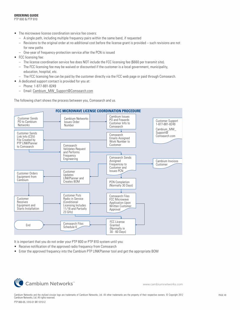
PAGE 49
ORDERING GUIDE PTP 800 & PTP 810
• The microwave license coordination service fee covers: – A single path, including multiple frequency pairs within the same band, if requested – Revisions to the original order at no additional cost before the license grant is provided – such revisions are not
for new paths – One-year of frequency-protection service after the PCN is issued • FCC licensing fee: – The license coordination service fee does NOT include the FCC licensing fee ($660 per transmit site). – The FCC licensing fee may be waived or discounted if the customer is a local government, municipality,
education, hospital, etc. – The FCC licensing fee can be paid by the customer directly via the FCC web page or paid through Comsearch.• A dedicated support contact is provided for you at: – Phone: 1-877-881-8249 – Email: [email protected]
The following chart shows the process between you, Comsearch and us.
Customer Sends PO to Cambium Networks
Cambium NetworksIssues Order Number
Cambium Issues PO and FowardsCustomer Info toComsearch
Comsearch Emails AssignedWork Number toCustomer
CustomerUpdatesLINKPlanner andCreates BOM
Customer ReceivesEquipment and Starts Installation
Customer PutsRadio in Service(ConditionalLicensing Includes11/18 and Partially23 GHz)
Customer SendsLink Info (CSV)File Created byPTP LINKPlannerto Comsearch Comsearch
Validates Requestand PerformsFrequencyEngineering Comsearch Sends
AssignedFrequencey toCustomer andIssues PCN
Cambium InvoicesCustomer
Comsearch FilesSchedule K
Customer Support1-877-881-8249
PCN Completion(Normally 30 Days)
Customer OrdersEquipment fromCambium
FCC LicenseGranted(Normally in 30 - 60 Days)
Comsearch FilesFCC MicrowaveApplication UponWritten CustomerApproval
End
FCC MICROWAVE LICENSE COORDINATION PROCEDURE
It is important that you do not order your PTP 800 or PTP 810 system until you:• Receive notification of the approved radio frequency from Comsearch• Enter the approved frequency into the Cambium PTP LINKPlanner tool and get the appropriate BOM
Cambium Networks and the stylized circular logo are trademarks of Cambium Networks, Ltd. All other trademarks are the property of their respective owners. © Copyright 2012 Cambium Networks, Ltd. All rights reserved.
PTP 800-05 / 810-01 BR 101512
www.cambiumnetworks.com TM