
PTC 220 Requirements for Private Voice Networks connected ... · PTC 220 . 1 SCOPE . This...
89
PTC 220 Requirements for Private Voice Networks connected to the PSTN/ISDN/VoIP public networks Access Standards Spark NZ Trading Limited Wellington NEW ZEALAND July 30, 2019
Transcript of PTC 220 Requirements for Private Voice Networks connected ... · PTC 220 . 1 SCOPE . This...
PTC 220
Requirements for Private Voice Networks connected to the PSTN/ISDN/VoIP public networks
Access Standards Spark NZ Trading Limited Wellington NEW ZEALAND
July 30, 2019
July 30, 2019 2 PTC 220
PTC220 Requirements for Private Voice Networks connected to the PSTN/ISDN/VoIP public networks CONTENTS 2 References 2 Foreword 4 Spark New Zealand Disclaimer 5 1 Scope 6 2 General 6 3 Definitions 10 4 Transmission Overview 12 5 FXS Requirements 27 6 FXO Requirements 43 7 FXD Requirements 61 8 System Specific (including IP) Telephone
Requirements 71 9 Voice Mail system Requirements 78 10 Interactive Voice Response Systems 80 11 Evaluating the Transmission Parameters
of Small Switching Systems using Applied Loudness ratings 83

July 30, 2019 3 PTC 220
References PTC 200:2006 Requirements for Connection of Customer Equipment to Analogue Lines PTC 208:2016 Specification of the PTC Requirements for Headsets for use in Telephony applications PTC 229:2018 Specification for Customer Equipment connecting to Spark New Zealand Voice Connect SIP Trunking network ITU-T Recommendation G.107:2015 The E-model: a computational model for use in transmission planning ITU-T Recommendation Q.24: Multifrequency Push-Button Signal Reception AS/NZS 60950 Australia/New Zealand Electrical Safety Requirements for IT equipment NOTE: the new Electrical Safety Standard AS/NZS 62368.1:2018 will be
replacing 60950 on 15th February 2022. AS/NZS CISPR 22/32 Australia/New Zealand Electromagnetic Compatibility Requirements for IT equipment DSL Forum TR 122 Base Requirements for Customer-Oriented Analogue Terminal Adapter Functionality
July 30, 2019 4 PTC 220
FOREWORD The purpose of this Specification is to ensure that the ITU-T Recommendations for overall end to end performance are satisfied when private voice networks are connected to the Spark New Zealand network. This Specification covers the minimum technical requirements for the grant of Telepermits for such connection. This Specification also covers a broad range of recommended parameters to assist those manufacturers who wish to exceed the stated minimum requirements. This Specification makes a clear distinction between these “mandatory” and “voluntary” performance requirements. The coverage of this Specification includes the full range of private voice networks from a simple single line FSO/FXS system to a large multi-node private voice network with multiple gateways into the PSTN and ISDN. This Specification includes the definition of requirements which ensure a reasonable expectation that private network users will be able to make calls into, and receive calls from the Spark New Zealand network. This Specification includes provisions for key aspects only to be tested. Other aspects affecting performance indirectly or in only a few network situations are not a part of the formal test requirement for the grant of a Telepermit. Nevertheless, for reliable operation under all circumstances, these additional aspects need to be complied with. Private voice networks are increasingly using packet technology to achieve cost savings by enabling voice and data to be transported and switched by common equipment. The voice performance of such networks can be affected by network topology, network provisioning, and network loading, which are all outside the scope of a PTC Specification. For the purposes of PTC testing, the equipment is configured in such a way that any degradation due to network design is minimised. It should be noted that in a real network implementation the performance can be no better than the results from the PTC tests. The Telepermit system requires that suppliers accept responsibility for the quality and reliability of their products. The granting of a Telepermit is not an acceptance of such responsibilities by Spark New Zealand, nor is it an endorsement of that product by Spark New Zealand. It is simply a public statement that the product concerned may be lawfully connected to the Spark New Zealand network. Under New Zealand consumer legislation, suppliers have legal responsibilities to ensure that their products are suitable for their intended purpose. As such, they are responsible for ensuring that any conditions relating to the grant of a Telepermit are made known to their network designers, installers and customers.
July 30, 2019 5 PTC 220
Spark New Zealand DISCLAIMER Spark New Zealand makes no representation or warranty, express or implied, with respect to the sufficiency, accuracy, or utility of any information or opinion contained in this Specification. Spark New Zealand expressly advises that any use of or reliance on such information is at the risk of the person concerned. Spark New Zealand shall not be liable for any loss (including consequential loss), damage or injury incurred by any person or organisation arising out of the sufficiency, accuracy, or utility of any such information or opinion. The grant of a Telepermit for any item of terminal equipment indicates only that Spark New Zealand has accepted that the item complies with minimum conditions for connection to its network. It indicates no endorsement of the product by Spark New Zealand, nor does it provide any sort of warranty. Above all, it provides no assurance that any item will work correctly in all respects with another item of Telepermitted equipment of a different make or model, nor does it imply that any product is compatible with all of Spark New Zealand’s network services.
July 30, 2019 6 PTC 220
1 SCOPE This Specification covers the requirements for private voice networks which are connected as customer equipment to the Spark New Zealand PSTN/ISDN and SIP Trunking networks. It is not technology specific and is intended to cover traditional circuit switched PABXs as well as VoIP. 2 GENERAL 2.1 PTC 100 The details of the Telepermit system of which this Specification forms a part are documented in PTC 100. 2.2 Mode of presentation (1) The requirements of this Specification are printed in plain type with each paragraph formally numbered. Informal comments, recommendations and explanations which are added only as indications of the means of compliance with this specification are shown in italics. Smaller type is used and each
paragraph is preceded with a "•" symbol instead of a clause number. (2) Mandatory requirements are indicated by use of "shall". (3) Voluntary and preferred requirements or recommendations are indicated by use "should" or "may". 2.3 Equipment Configuration profiles (1) Much of the equipment covered by this specification is highly configurable by software, firmware or configuration processes performed at installation time. (2) When equipment is submitted for testing the correct configuration details and instructions for connection to the Spark New Zealand Network shall be supplied to the Test Laboratory. These details and instructions shall be same as those intended to be supplied to the end customer or installer. (3) It is preferable that configurations compliant with Telepermit requirements are preloaded prior to supply, or invoked by a simple "NZ" command. (4) Configuration profiles shall not be lost in the event of a power failure. (5) Critical configuration details, i.e. network compatibility parameters such as loudness ratings, ISDN profiles etc, shall not be accessible by ordinary users. (5) Remote configuration procedures shall have adequate security to prevent hackers obtaining access to system configuration files.
July 30, 2019 7 PTC 220
2.4 Other Regulatory Requirements 2.4.1 Electrical safety 2.4.1.1 General All equipment intended for connection to the Spark New Zealand network, including plug-in cards and modules, shall conform to the safety requirements of the joint Australian and New Zealand standard, AS/NZS 60950. • This should not be confused with the definition of ELV applicable to electrical wiring
covered by the New Zealand Electricity Regulations, where it is defined as 32 Vac rms and 115 V dc.
• A considerable proportion of telecommunications equipment available is manufactured for the North American and Japanese markets, where the mains voltage is only 100-110 V. Such overseas equipment may be compliant with the North American local requirements, but designed with inadequate internal clearances between its components to meet New Zealand requirements, which are based on 230 V operation.
2.4.1.2 External power supplies (1) Where the equipment is to be used with a separate external power supply, the combination of equipment plus power supply shall comply with the requirements of AS/NZS 60950. • Compliance testing to AS/NZS 60950, may only be undertaken by an IANZ registered
laboratory, one which has been accredited by an IANZ affiliated laboratory registration authority, or one which is recognised by Worksafe New Zealand.
(2) Where the equipment is to be used with a separate external power supply and a non-proprietary power supply is used, the operating voltage and current rating (and preferably the polarity of the connector) should be marked on the case adjacent to the socket concerned. • This recommendation avoids the risk of an unsuitable power supply being connected via
a standard or commonly used type of connector.
(3) External Power adapters including battery chargers have been classified as “High Risk” products and must have a Certificate of Compliance issued by an Authority recognised by Worksafe New Zealand. 2.4.1.3 Earth connections (1) Where, for any reason, an earth connection is necessary for the correct operation of any equipment, the requirements of AS/NZS 60950 shall be complied with. • Suppliers should note that such telecommunications equipment is referenced to both the
local earth and the remote telephone exchange earth. In the event of power faults or lightning strikes causing a rise in earth potential in the vicinity of the customer's premises, insulation breakdown is likely to result.
July 30, 2019 8 PTC 220
(2) Details of any earth connections required and the most appropriate ways of providing them shall be incorporated within the 'User Instructions' supplied with the equipment concerned. 2.4.2 Electromagnetic interference (EMI) (1) All equipment shall comply with the Radiocommunications Act 1989 and Radiocommunications (Radio) Regulations 1993 as regards radiated energy. These requirements are administered by the Ministry of Business, Innovation and Employment. • Any microprocessor-based equipment is likely to give rise to unwanted radiation and it is
advisable that this aspect be checked before any equipment is released onto the New Zealand market.
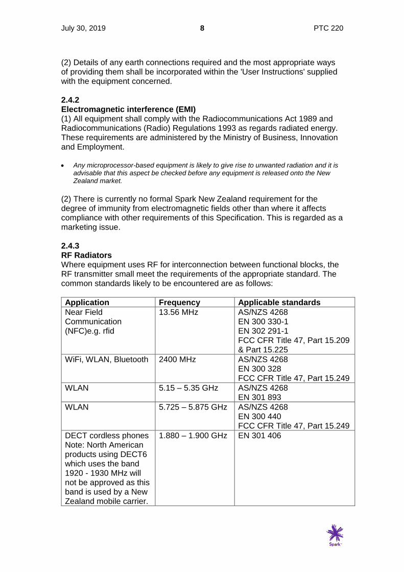
(2) There is currently no formal Spark New Zealand requirement for the degree of immunity from electromagnetic fields other than where it affects compliance with other requirements of this Specification. This is regarded as a marketing issue. 2.4.3 RF Radiators Where equipment uses RF for interconnection between functional blocks, the RF transmitter small meet the requirements of the appropriate standard. The common standards likely to be encountered are as follows:
Application Frequency Applicable standards
Near Field Communication (NFC)e.g. rfid
13.56 MHz AS/NZS 4268 EN 300 330-1 EN 302 291-1 FCC CFR Title 47, Part 15.209 & Part 15.225
WiFi, WLAN, Bluetooth 2400 MHz AS/NZS 4268 EN 300 328 FCC CFR Title 47, Part 15.249
WLAN 5.15 – 5.35 GHz AS/NZS 4268 EN 301 893
WLAN 5.725 – 5.875 GHz AS/NZS 4268 EN 300 440 FCC CFR Title 47, Part 15.249
DECT cordless phones Note: North American products using DECT6 which uses the band 1920 - 1930 MHz will not be approved as this band is used by a New Zealand mobile carrier.
1.880 – 1.900 GHz EN 301 406

July 30, 2019 9 PTC 220
2.5 Temperature All products should be compliant with this Specification at all temperatures in the range -10 degrees C to +40 degrees C.
July 30, 2019 10 PTC 220
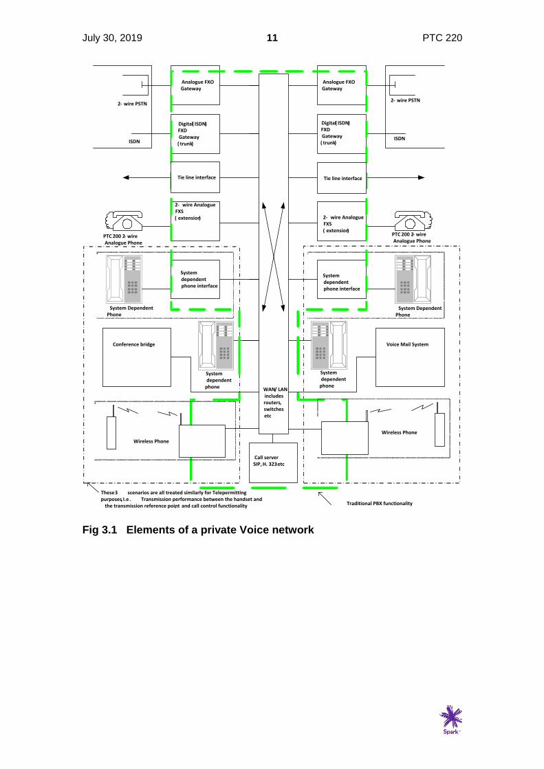
3 DEFINITIONS 3.1 General (1) The basic elements of a private voice network are shown in figure 3.1. The centre block labelled WAN/LAN could be implemented using a number of different technologies, for example analogue cross-point switch, TDM digital, IP/Ethernet, or wireless. While the majority of such systems will have some form of switching included, the specification is also applicable to simple point to point loop extenders employing digital/analogue or wireless technologies. (2) It has been noted that some terms have been used by manufacturers in different ways. For the avoidance of confusion over terms used in this Specification, they are defined as follows:- ATA: Analogue Telephone Adapter. See FXS below FXS: Foreign eXchange Subscriber interface. This equipment interfaces a transmission link to standard PTC 200 compliant CPE. The transmission link is commonly IP based in distributed network solutions, and will be connected back to a central office switch via an FXO interface. The same functionality exists in a PBX extension module, although the transmission link may be the backplane in the equipment cabinet, and the protocols proprietary. FXO: Foreign eXchange central Office interface. This equipment interfaces a transmission link to a 2-wire analogue port on a central office switch. See also FXS, FXD. In PBX terminology this functionality would be contained in an analogue trunk module. FXD: Foreign eXchange central office Digital interface. This equipment interfaces a transmission link to a digital port, either E1, ISDN or SIP Trunking with a public network. See also FXS, FXO. In PBX terminology this functionality would be contained in an ISDN or E1 trunk module. Acoustic Reference Level (ARL): The acoustic level which gives -10 dBm0 at the digital reference point. D-factor: The computed average of the difference between the sending sensitivity using an artificial mouth and that using a diffuse room noise source. TRP: Transmission Reference Point, also known as the 0 dBr point. Point within network where losses are measured from and to.
July 30, 2019 11 PTC 220
PTC 200 2- wire Analogue Phone
Analogue FXOGateway
Digital( ISDN)FXDGateway
( trunk)
2- wire Analogue FXS( extension)
System dependent phone interface
System dependent
phone
System dependent
phone
System dependent phone interface
2- wire Analogue FXS( extension)
Digital( ISDN)FXDGateway
( trunk)
Analogue FXOGateway
2- wire PSTN
ISDN
2- wire PSTN
ISDN
PTC 200 2- wire Analogue Phone
System Dependent Phone
System Dependent Phone
Traditional PBX functionality
These 3 scenarios are all treated similarly for Telepermitting purposes, I.e . Transmission performance between the handset and
the transmission reference point, and call control functionality
Call serverSIP, H. 323 etc
WAN/ LAN includes routers, switchesetc
Wireless Phone
Wireless Phone
Voice Mail SystemConference bridge
Tie line interface Tie line interface
Fig 3.1 Elements of a private Voice network
July 30, 2019 12 PTC 220
4 TRANSMISSION OVERVIEW 4.1 General This section covers parameters which deal directly with the quality of the voice signals themselves. They include transmission level plans, impedance plans (for analogue interfaces), delay plans, and methods of managing distortion. The test requirements for network elements, such as FXS equipment, system dependent (such as IP) phones etc are covered in detail in sections 5 on. 4.2 E-model (1) When PTC 207 and PTC 217 were written, transmission impairments were dealt with using Quantization Distortion Units (QDUs). These were originally intended to quantify the distortion for an A or mu law codec pair in such a way that the overall effect of multiple conversions between analogue and digital could be assessed by adding the QDUs together. While QDUs were assigned to low bit rate encoders based on group assessment processes, these were found to be inadequate for all but very simple networks. The E-model was subsequently developed by ETSI to take account of all the impairments which lead to speech degradation, and in particular takes into account impairments which typically occur in packet based networks. In the E-model, impairment values are assigned to a number of independent parameters, which are then combined to give a transmission rating factor R as follows:
R = Ro – Is – Id – Ie + A
Ro represents in principle the basic signal-to-noise ratio, including noise sources such as circuit noise and room noise. Is is a combination of all impairments which occur more or less simultaneously with the voice signal. This includes loudness, sidetone, and quantizing distortion from analogue/digital conversions. Id represents the impairments caused by delay, which include Talker and Listener echo, and end to end delay. Ie represents impairments caused by low bit rate codecs. A is the expectation factor which allows for compensation of impairment factors when there are other advantages of access to the user, such as mobility. • Some parameters particularly receive and send loudness ratings impact on more than
one impairment factor.
• Some factors are determined in terminal equipment. For example in digital networks which are in themselves lossless Loudness ratings are determined entirely by terminal equipment (phone) design. Other factors such as delay. are partly determined in terminal

July 30, 2019 13 PTC 220
equipment design, partly determined in network design, and in packet networks, could vary according to network loading.
AD
AD
DA
DA
0 dBr point
Send side Receive sideOLR
RLRSLR
Round Trip Delay Tr
Weighted echo path loss WEPL
Room Noise Pr
Dr-factor Ds-factor
Room Noise Ps
Sidetone masking rating STMR
Listener sidetone rating LSTR (LSTR = STMR + Dr)
Talker echo loudness rating TELR
Mean one-way delay T
Absolute delay Ta
Network Impairments
Circuit Noise Nc referred to 0 dBr
Equipment impairment factor IePacket loss robustness factor BplPacket loss probability Ppl
Quantizing distortion qduExpectation factor A
Fig 4.1 E-model reference connection Of all the parameters shown in the above diagram, some arise from customer equipment design, some from network design and some are a combination of both. This specification is concerned mainly with the parameters determined by customer equipment design and also the delay parameter which occurs in both customer equipment and the network. 4.2.2 E-model Parameters The parameters used in calculating the R factor are listed in the table below: PARAMETER Unit Objective/default
Value Range
Send Loudness Rating SLR dB +8 0 …+18
Receive Loudness Rating RLR dB +2 -5 … +14
Sidetone Masking Rating STMR dB 15 10 … 20
Listener Sidetone Rating LSTR dB 18 13 … 23
D-Value of Telephone, Send side
Ds dB 3 -3 …+3
D-Value of Telephone, Receive side
Dr dB 3 -3 …+3
Talker Echo Loudness Rating TELR dB 65 5 …65
Weighted Echo Path Loss WEPL dB 110 5 …110
Echo Path Mean one-way delay
T ms 0 0...500
4-wire Round Trip delay Tr ms 0 0 …1000
Absolute Delay in Echo-free Connection
Ta ms 0 0 …500
Quantization Distortion Units qdu - 1 1 …14
Equipment Impairment Factor Ie - 0 0 … 40
Packet-loss Robustness Factor
Bpl - 1 1 … 40
July 30, 2019 14 PTC 220
Random Packet Loss Probability
Ppl % 0 0 … 20
Burst Ratio BurstR - 1 1 … 2
Circuit Noise referred to 0 dBr point
Nc dBm0p -70 -80 …-40
Noise Floor at Receive Side Nfor dBmp -64 -
Room Noise at Send Side Ps dB(A) 35 35 … 85
Room Noise at Receive Side Pr dB(A) 35 35 … 85
Advantage Factor A - 0 0 … 20
• Reference ITU-T Recommendation G.107 Table 2
• The requirements for customer equipment in this Specification assume that network parameters are set at objective or optimum values, so on a real network the performance may be worse than that experienced between two pieces of CPE connected together by a short cable. It is expected that as networks improve, they will behave as per the default values given in the table above, with the exception of the delay values which are set ultimately by propagation delay and coding/packetization delays.
• It could be expected that as transmission speeds and network capacities rise, the need for efficient low bit rate codecs will diminish, and so the impairments will be predominantly due to the CPE parameters (loudness ratings, STMR, D-factor) and network propagation delay.
• The D-factor is not measured as part of this specification. It is assumed to be +3 but could be higher than that with the increasing use of noise cancelling microphones particularly in small handsets.
4.3 Transmission Levels and Loss Plan This part of the specification outlines the requirements for transmission levels in a private voice network which is connected as customer equipment to the Spark New Zealand PSTN/ISDN. The transmission plan is designed to allow good performance in an any to any call scenario, including the mixing of analogue and digital phones and interfaces. 4.3.1 Design Objectives (1) Proposed pads and levels are optimised for the long-term “all-digital” situation. Ultimately, the circuit-switched public network is likely to be replaced by an IP network which will directly connect into a private IP network. (2) Network planning and digital terminal design for voice functionality shall comply with the ITU Overall Loudness Rating objectives of 10 dB, with SLR of +8 dB, RLR of +2 dB and no circuit losses. (3) It is recognised that most traffic on a private network is “extension to extension”, whether the terminals are all digital or mixed analogue and digital. As such, the FXS pad values are optimised for this situation and set at “standard values” for use in all circumstances. • Analogue terminal loudness ratings incorporate allowances for the traffic weighted mean
trunk loss. Ref Figs 4.3.3 and 4.4.4.

July 30, 2019 15 PTC 220
(4) The level/loss plan recognises that digital trunks should always be used between the digital PSTN and the private IP network. In this case, the zero level point is simply extended from the PSTN into the private IP network, with no pads or gains in the interface. (5) In the event that analogue trunks are the only option available. The default FXO settings of Fig 4.3.3 are gains to compensate for the T and R pads used in the PSTN. This means that private IP networks interfacing with the PSTN via analogue trunks suffer a transmission level loss relative to the optimum. This loss would be exacerbated in cases where long analogue trunks have to be used. While the FXO gains may be adjusted to compensate for analogue trunk loss in such cases, it is unlikely that long analogue trunks will be encountered. (6) Loss values appear in the impairment calculations for most of the components which determine the overall R-value in the E-model. It is therefore highly desirable that the losses are set as close as possible to the optimum values. In most modern equipment these are software settings, and as such there is no additional cost in implementing the correct settings. (7) Echo cancellation shall be incorporated in all interfaces to the PSTN where there is any likelihood of the delay in the private network exceeding 15 ms. This would be always required in a VoIP system but not in a circuit switched PABX or
keyphone system. 4.3.2 Testing All level measurements shall be performed with G.711 A-law codecs utilised. Performance using other codecs cannot be measured using standard techniques, and in the interim, the performance of non-waveform codecs should be determined by subjective comparison. Any echo cancellers shall be turned on, and any silence suppression processes should be turned off.
July 30, 2019 16 PTC 220
4.3.3 Analogue FXS, Analogue FXO
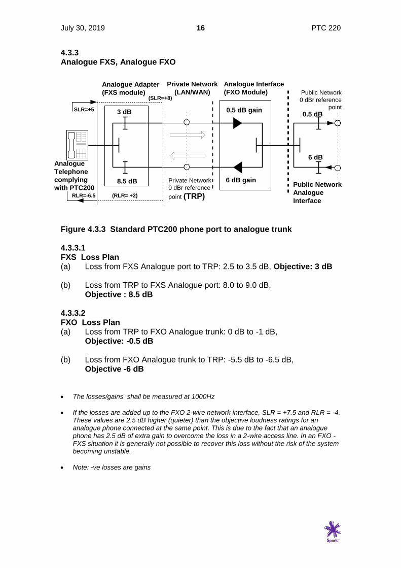
Figure 4.3.3 Standard PTC200 phone port to analogue trunk 4.3.3.1 FXS Loss Plan (a) Loss from FXS Analogue port to TRP: 2.5 to 3.5 dB, Objective: 3 dB (b) Loss from TRP to FXS Analogue port: 8.0 to 9.0 dB,
Objective : 8.5 dB 4.3.3.2 FXO Loss Plan (a) Loss from TRP to FXO Analogue trunk: 0 dB to -1 dB,
Objective: -0.5 dB (b) Loss from FXO Analogue trunk to TRP: -5.5 dB to -6.5 dB,
Objective -6 dB • The losses/gains shall be measured at 1000Hz
• If the losses are added up to the FXO 2-wire network interface, SLR = +7.5 and RLR = -4. These values are 2.5 dB higher (quieter) than the objective loudness ratings for an analogue phone connected at the same point. This is due to the fact that an analogue phone has 2.5 dB of extra gain to overcome the loss in a 2-wire access line. In an FXO - FXS situation it is generally not possible to recover this loss without the risk of the system becoming unstable.
• Note: -ve losses are gains
Private Network
(LAN/WAN)
Analogue Interface
(FXO Module)
Analogue
Telephone
complying
with PTC200
0.5 dB gain
6 dB gain
6 dB
0.5 dB3 dB
8.5 dB
Analogue Adapter
(FXS module)
RLR=-6.5 (RLR= +2)
SLR=+5
(SLR=+8)
Public Network
Analogue
Interface
Private Network
0 dBr reference
point (TRP)
Public Network
0 dBr reference
point

July 30, 2019 17 PTC 220
4.3.3.3 Network Loss The allowable range for each loss/gain element is the objective +/- 0.5 dB. However this range is large enough that if the wrong extremes are implemented instability could arise. Therefore the values implemented shall be such that the end to end loss shall be as follows: (a) Loss from FXS port to FXO port: 2 to 3 dB, Objective: 2.5 dB (b) Loss from FXO port to FXS port: 2 to 3 dB, Objective 2.5 dB
July 30, 2019 18 PTC 220
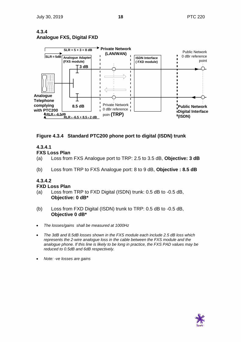
4.3.4 Analogue FXS, Digital FXD
Figure 4.3.4 Standard PTC200 phone port to digital (ISDN) trunk 4.3.4.1 FXS Loss Plan (a) Loss from FXS Analogue port to TRP: 2.5 to 3.5 dB, Objective: 3 dB (b) Loss from TRP to FXS Analogue port: 8 to 9 dB, Objective : 8.5 dB 4.3.4.2 FXD Loss Plan (a) Loss from TRP to FXD Digital (ISDN) trunk: 0.5 dB to -0.5 dB,
Objective: 0 dB* (b) Loss from FXD Digital (ISDN) trunk to TRP: 0.5 dB to -0.5 dB,
Objective 0 dB* • The losses/gains shall be measured at 1000Hz
• The 3dB and 8.5dB losses shown in the FXS module each include 2.5 dB loss which represents the 2-wire analogue loss in the cable between the FXS module and the analogue phone. If this line is likely to be long in practice, the FXS PAD values may be reduced to 0.5dB and 6dB respectively.
• Note: -ve losses are gains
Private Network
(LAN/WAN)
Analogue
Telephone
complying
with PTC200Public Network
Digital Interface
(ISDN)
3 dB
8.5 dB
Analogue Adapter
(FXS module)ISDN Interface
( FXD module)
Private Network
0 dBr reference
poin (TRP)
Public Network
0 dBr reference
point
RLR = -6.5dBRLR = -6.5 + 8.5 = 2 dB
SLR = 5dB
SLR = 5 + 3 = 8 dB

July 30, 2019 19 PTC 220
4.3.5 Digital Phone to analogue FXO
Figure 4.3.5 Digital Phone connected via analogue FXO 4.3.5.1 Digital Phone Loudness Rating (a) SLR to TRP: +5 dB to + 11 dB, Objective: +8 dB (a) RLR to TRP: -1 dB to + 5 dB, Objective: +2 dB 4.3.5.2 FXO Loss Plan (a) Loss from TRP to FXO Analogue trunk: 0 dB to -1 dB,
Objective: -0.5 dB (b) Loss from FXO Analogue trunk to TRP: -5.5 dB to -6.5 dB,
Objective -6 dB • The losses/gains shall be measured at 1000Hz
• The variation of gain/loss shall be not more than +/- 0.5dB of the 1000 Hz value across the frequency band 300 to 3400 Hz
• If the losses are added up to the FXO 2-wire network interface, SLR = +7.5 and RLR = -4.
These values are 2.5 dB higher (quieter) than the objective loudness ratings for an analogue phone connected at the same point. This is due to the fact that an analogue phone has 2.5 dB of extra gain to overcome the loss in a 2-wire access line. While it would be possible to add some additional gain This would lead to the possibility of instability if an FXS module were connected to the private network 0 dBr point. As with the analogue FXO connection shown in Fig 2.3.3, this illustrates the inherent problems with using 2-wire analogue connections between a private network and the public network.
Private Network
(LAN/WAN)
Digital
I/F
Analogue Interface
(FXO module)
Digital
Telephone
0.5 dB gain
6 dB gain
6 dB
0.5 dB
Public Network
Analogue
Interface
SLR = +8 - FXO transmit gain (db)
RLR = +2 - FXO receive gain (dB)
RLR = +2
SLR = +8
Private Network
0 dBr reference
point
Public Network
0 dBr reference
point
July 30, 2019 20 PTC 220
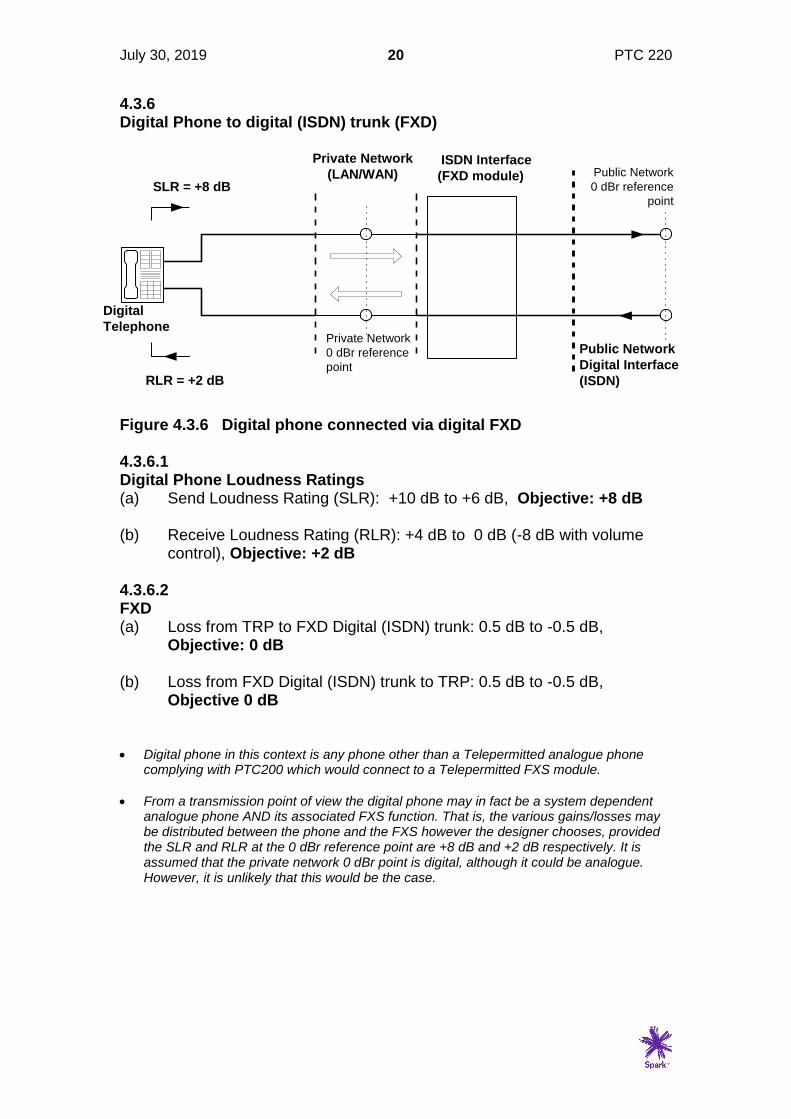
4.3.6 Digital Phone to digital (ISDN) trunk (FXD)
Figure 4.3.6 Digital phone connected via digital FXD 4.3.6.1 Digital Phone Loudness Ratings (a) Send Loudness Rating (SLR): +10 dB to +6 dB, Objective: +8 dB (b) Receive Loudness Rating (RLR): +4 dB to 0 dB (-8 dB with volume
control), Objective: +2 dB 4.3.6.2 FXD (a) Loss from TRP to FXD Digital (ISDN) trunk: 0.5 dB to -0.5 dB,
Objective: 0 dB (b) Loss from FXD Digital (ISDN) trunk to TRP: 0.5 dB to -0.5 dB,
Objective 0 dB • Digital phone in this context is any phone other than a Telepermitted analogue phone
complying with PTC200 which would connect to a Telepermitted FXS module.
• From a transmission point of view the digital phone may in fact be a system dependent analogue phone AND its associated FXS function. That is, the various gains/losses may be distributed between the phone and the FXS however the designer chooses, provided the SLR and RLR at the 0 dBr reference point are +8 dB and +2 dB respectively. It is assumed that the private network 0 dBr point is digital, although it could be analogue. However, it is unlikely that this would be the case.
Private Network
(LAN/WAN)
Digital
Telephone
Public Network
Digital Interface
(ISDN)
ISDN Interface
(FXD module)
RLR = +2 dB
SLR = +8 dB
Private Network
0 dBr reference
point
Public Network
0 dBr reference
point
July 30, 2019 21 PTC 220
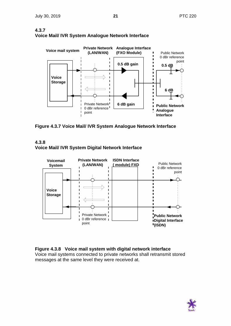
4.3.7 Voice Mail/ IVR System Analogue Network Interface
Figure 4.3.7 Voice Mail/ IVR System Analogue Network Interface 4.3.8 Voice Mail/ IVR System Digital Network Interface
Figure 4.3.8 Voice mail system with digital network interface Voice mail systems connected to private networks shall retransmit stored messages at the same level they were received at.
Private Network
(LAN/WAN)
Analogue Interface
(FXO Module)
0.5 dB gain
6 dB gain
6 dB
0.5 dB
Voice mail system
Public Network
Analogue
Interface
Private Network
0 dBr reference
point
Public Network
0 dBr reference
point
Voice
Storage
Private Network
(LAN/WAN)
Public Network
Digital Interface
(ISDN)
ISDN Interface
( module) FXD
Private Network
0 dBr reference
point
Public Network
0 dBr reference
point
Voicemail
System
Voice
Storage
July 30, 2019 22 PTC 220
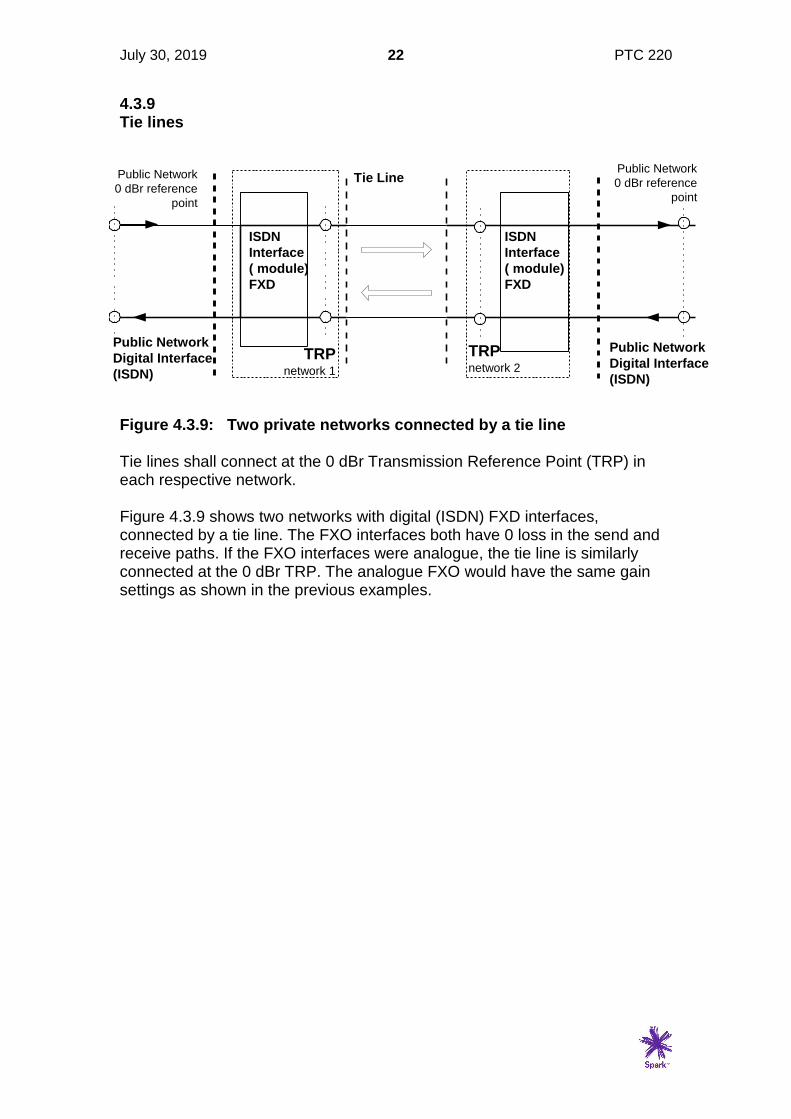
4.3.9 Tie lines
Figure 4.3.9: Two private networks connected by a tie line Tie lines shall connect at the 0 dBr Transmission Reference Point (TRP) in each respective network. Figure 4.3.9 shows two networks with digital (ISDN) FXD interfaces, connected by a tie line. The FXO interfaces both have 0 loss in the send and receive paths. If the FXO interfaces were analogue, the tie line is similarly connected at the 0 dBr TRP. The analogue FXO would have the same gain settings as shown in the previous examples.
Tie Line
Public Network
Digital Interface
(ISDN)
TRPnetwork 2
ISDN
Interface
( module)
FXD
Public Network
0 dBr reference
point
ISDN
Interface
( module)
FXD
Public Network
0 dBr reference
point
Public Network
Digital Interface
(ISDN)
TRPnetwork 1
July 30, 2019 23 PTC 220
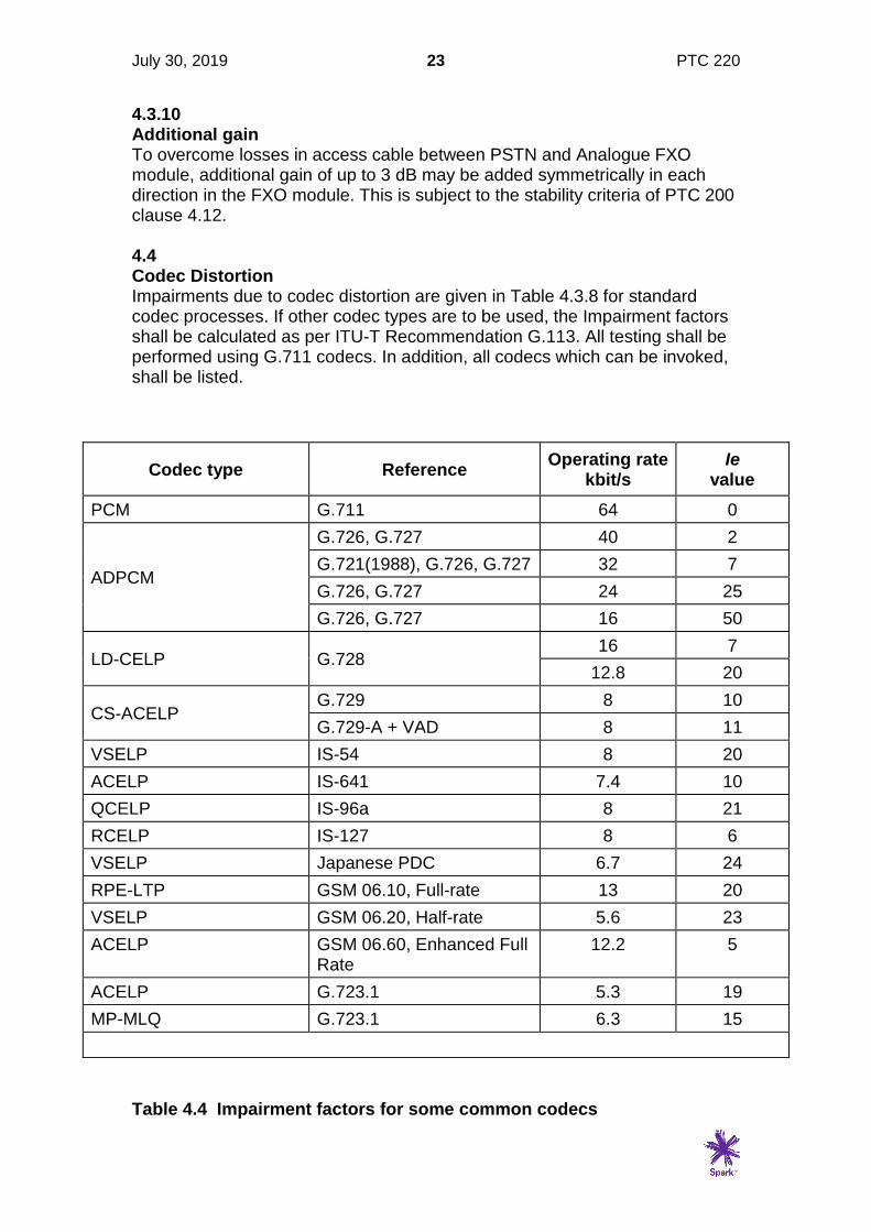
4.3.10 Additional gain To overcome losses in access cable between PSTN and Analogue FXO module, additional gain of up to 3 dB may be added symmetrically in each direction in the FXO module. This is subject to the stability criteria of PTC 200 clause 4.12. 4.4 Codec Distortion Impairments due to codec distortion are given in Table 4.3.8 for standard codec processes. If other codec types are to be used, the Impairment factors shall be calculated as per ITU-T Recommendation G.113. All testing shall be performed using G.711 codecs. In addition, all codecs which can be invoked, shall be listed.
Codec type Reference Operating rate
kbit/s Ie
value
PCM G.711 64 0
ADPCM
G.726, G.727 40 2
G.721(1988), G.726, G.727 32 7
G.726, G.727 24 25
G.726, G.727 16 50
LD-CELP G.728 16 7
12.8 20
CS-ACELP G.729 8 10
G.729-A + VAD 8 11
VSELP IS-54 8 20
ACELP IS-641 7.4 10
QCELP IS-96a 8 21
RCELP IS-127 8 6
VSELP Japanese PDC 6.7 24
RPE-LTP GSM 06.10, Full-rate 13 20
VSELP GSM 06.20, Half-rate 5.6 23
ACELP GSM 06.60, Enhanced Full Rate
12.2 5
ACELP G.723.1 5.3 19
MP-MLQ G.723.1 6.3 15
Table 4.4 Impairment factors for some common codecs
July 30, 2019 24 PTC 220
4.5 Delay Delays of more than about 150ms in an end to end call begin to affect ease of conversation even in the absence of echo. Delays exceeding 400 ms are considered unacceptable by ITU (ITU-T Rec. G.114) but it is acknowledged that this will be exceeded in some exceptional cases, for example a 2-hop satellite link to a remote Pacific Island. Delays on circuit based connections:
• National (NZ) calls up to around 15 ms
• NZ-UK cable only 150 ms
• NZ-UK cable/satellite 300 ms (satellite propagation delay is 260 ms).
• Mobile systems such as GSM and CDMA introduce around 100 ms of additional delay on calls to the PSTN.
• Low bit rate encoding and digital processes in packet based systems tend to add significant delay.
• Further information on delay can be found in ITU-T recommendation G.114 (05/00) “One-way transmission time”.
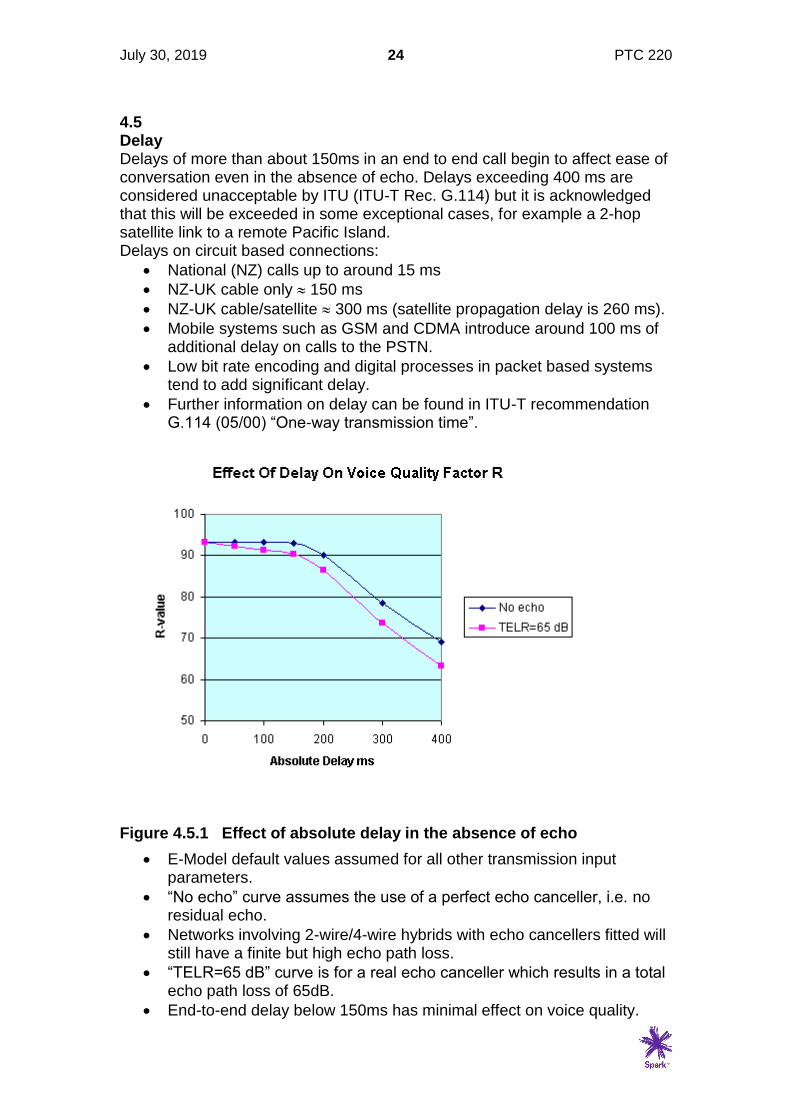
Figure 4.5.1 Effect of absolute delay in the absence of echo
• E-Model default values assumed for all other transmission input parameters.
• “No echo” curve assumes the use of a perfect echo canceller, i.e. no residual echo.
• Networks involving 2-wire/4-wire hybrids with echo cancellers fitted will still have a finite but high echo path loss.
• “TELR=65 dB” curve is for a real echo canceller which results in a total echo path loss of 65dB.
• End-to-end delay below 150ms has minimal effect on voice quality.
July 30, 2019 25 PTC 220
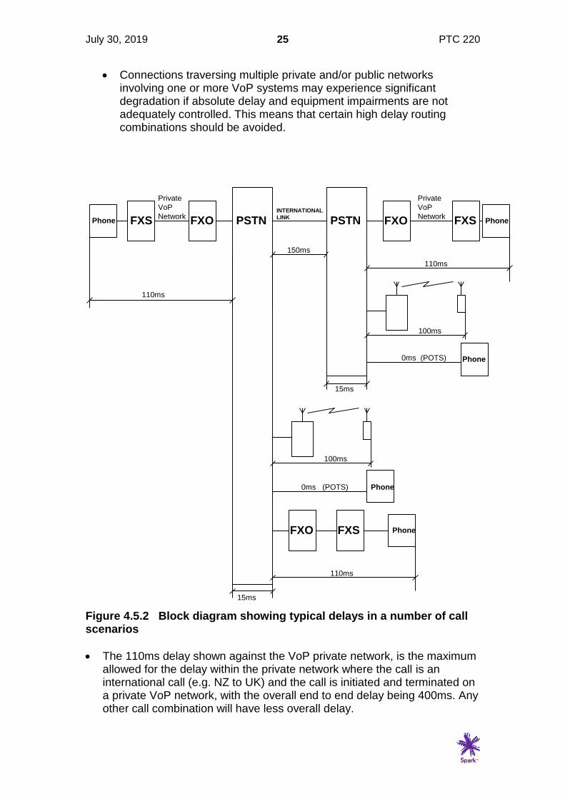
• Connections traversing multiple private and/or public networks involving one or more VoP systems may experience significant degradation if absolute delay and equipment impairments are not adequately controlled. This means that certain high delay routing combinations should be avoided.
Figure 4.5.2 Block diagram showing typical delays in a number of call scenarios
• The 110ms delay shown against the VoP private network, is the maximum allowed for the delay within the private network where the call is an international call (e.g. NZ to UK) and the call is initiated and terminated on a private VoP network, with the overall end to end delay being 400ms. Any other call combination will have less overall delay.
PSTNFXOPhone FXS PSTN FXO PhoneFXSINTERNATIONAL
LINK
15ms
110ms
110ms
Phone
100ms
0ms (POTS)
15ms
100ms
Phone0ms (POTS)
FXO PhoneFXS
110ms
150ms
Private
VoP
Network
Private
VoP
Network

July 30, 2019 26 PTC 220
• In an all packet network, the FXO functions and any delays associated with them disappear, but the delays within the national network are likely to increase.
4.6 Echo Where the mean one way propagation time exceeds 15ms echo cancellers shall be deployed. VoP and wireless technologies are likely to have inherent delays exceeding 15ms and would be expected to have echo cancellers fitted. Assuming echo cancellers are fitted, values of 65dB and 110dB are used for TELR and WEPL respectively in calculating the delay impairment factor Id. • Ref ITU-T Recommendation G.107
4.7 Noise The important factor with noise is the signal to noise ratio (SNR). One way to increase the SNR is to increase the end to end gain, i.e. reduce the Overall Loudness Rating (OLR), however there are limits on Send and Receive Loudness ratings which make this impractical beyond certain limits. The best solution is to reduce the various sources of noise as much as possible. From the sender to the receiver, the Sources of noise can be categorized as follows:
1. Background acoustic noise. This cannot be directly controlled, although its effect on communication can be partially mitigated by techniques such as filtering and noise cancelling microphones.
2. Circuit Noise. This is electrical noise induced into the signal at various
points in the end to end connection. This does not include noise due to distortion in any codecs which are dealt with as separate impairments. Common sources of such noise is switched mode power supplies, and induced noise from high frequency clock signals into analogue circuits. This is why it important that Analogue sub-systems such as FXS FXO and phones are tested with the same power supplies which will be used when the device is installed.

July 30, 2019 27 PTC 220
5.0 FXS Requirements 5.1 General This section covers the requirements for a standalone FXS unit with analogue ports for connection to a PTC200 series Telepermitted phone. Where an FXS unit is intended for connection to a proprietary (system dependent) phone, the phone and the FXS are tested together as a system dependent phone (see section 8). 5.1.1 Test Configuration The Test Laboratory shall document in the form of a block schematic, the configuration used for testing this section. This shall include the make and model of the FXO/D or Trunk interface used to complete some of the tests, and state where the TRP is located. • The TRP would normally be at the Ethernet interface to the FXS, or in the case of a circuit
switched PBX at the centre of the switch block.
• Examples of the block schematic are given in the test setups in Appendix 1 of this specification.
5.1.2 Configuration Details Actual setup configurations shall be recorded in the test report for all test results in this section. At least one FXS configuration must be able to achieve compliance for all parts of this specification. 5.2 Other Regulatory Requirements 5.2.1 Electrical Safety The unit shall meet the requirements of AS/NZS 60950. This includes the following FXS components: (a) Power Supply (b) LAN/WAN port(s) isolation to TNV (c) 2-wire analogue port, isolation to TNV (d) Ringing feed to meet TNV definition. See clause 5.6.2(b) of this Specification. • The voltages used for ringing are in the LV range, but if other conditions are met such as
duty cycle and source impedance, the ringing signal can be classified in the less dangerous TNV category.
5.2.2 Electromagnetic Compatibility (EMC) The product shall meet the requirements for Electromagnetic Compatibility, which are documented in AS/NZS CISPR22 or AS/NZS CISPR32. Equivalent international specifications are EN 55022 and EN55032.
July 30, 2019 28 PTC 220
5.2.3 Wireless Functions Where products include wireless functionality, these functions shall meet the requirements of the appropriate specification. See clause 2.4.3 for a list of requirements. 5.3 Transmission 5.3.1 Loss Plan (a) Loss from FXS Analogue port to TRP: 2.5 to 3.5 dB, Objective: 3 dB (b) Loss from TRP to FXS Analogue port: 8 to 9 dB, Objective: 8.5 dB • PTC220 clause 4.3.3.1 (4.3.4.1)
(c) Where FXS equipment has more than one port the loss between ports shall be 11 to 12 dB in both directions, Objective 11.5 dB
• The above measurements to be taken at 1000Hz with a send level of -10 dBm0.
5.3.2 Attenuation Frequency Distortion The loss distortion with frequency between the FXS port and the TRP and the TRP and the 2-wire port shall be within the following limits, using an input level of -10 dBm0 at the TRP. Frequency Loss relative to the loss at 1000Hz (Hz) (dB) 300 - 400 +1, -0.3 400 - 600 +0.75, -0.3 600 - 2000 +0.35, -0.3 2000 - 2400 +0.45, -0.3 2400 - 3000 +0.7, -0.3 3000 - 3400 +1.7, -0.3 • Reference ITU Recommendation Q.552
July 30, 2019 29 PTC 220
5.3.3 Variation of Gain with input level With a 1000 Hz sinewave signal applied to either the FXS port or the TRP 0dBr point at a level between -55 dBm0 and +3 dBm0, the gain of that signal relative to the gain of a signal at an input level of -10 dBm0 at the TRP, shall be within the following limits: Input level Gain Variation (dBm0) (dB) -55 to -50 +/- 1.6 -50 to -40 +/- 0.6 -40 to +3 +/- 0.3 • ITU-T Recommendation Q.552 clause 3.1.1.4
5.3.4 Port Impedance There are two impedances associated with an FXS port. Firstly there is the input impedance of the port, and secondly the balance impedance. Both of these impedances are important for overall performance, with impedance mismatches causing, high sidetone in the telephone, low levels of speech, echo, and in the worst case instability. 5.3.4.1 Port Input Impedance The nominal input impedance used by Spark New Zealand is a 370 ohm resistor in series with a parallel combination of a 620 ohm resistor and a 310 nanofarad capacitor (known as BT3). For Telepermit compliance this is measured as a Return Loss against BT3, at the following frequencies: 200, 250, 315, 400, 500, 630, 800, 1000, 1250, 1600, 2000, 3150, 4000 Hz (a) The Return Loss shall not be less than 12dB at any of the above
frequencies. (b) The Echo Return Loss shall be not less than 14 dB. • The ELR shall be calculated according to the method given in ITU-T Recommendation G.122
5.3.4.2 Terminal Balance Return Loss (TBRL) Using the test method described in Appendix 5 of this specification, the TBRL shall exceed the limits shown in the figure below.

July 30, 2019 30 PTC 220
Figure 5.3.4.2 Terminal Balance Return Loss (TBRL) Requirement • reference ITU-T Recommendation Q.552 clause 3.1.8
5.3.4.3 Crosstalk between Ports Where FXS equipment has more than one analogue port there shall be a minimum of 50 dB isolation between individual ports over the range 300 - 3400 Hz. This shall apply to ports when in an off-hook condition. 5.3.4.4 Noise (1) With the analogue port terminated in 600 ohms (off-hook with speech path open but quiet) the noise shall be less than -65 dBmP (2) With the analogue port terminated in 10 kohms (on-hook) the noise shall be less than -65 dBmP
(3) The noise in any 3kHz bandwidth above 4kHz shall be below lines joining the points given in table 5.3.4.4.
FREQUENCY POWER SPECTRAL DENSITY (kHz) (dBm) 4.0 -40 10.0 -40 20.0 -50 50.0 -70 >50.0 & <100.0 -70 >100.0 & <10 MHz -50
Table 5.3.4.4 limits for noise above 4kHz on FXS port
300 500 2500 3400
16
20
dB
Hz
Frequency (f)
Te
rmin
al
Bala
nc
e R
etu
rn L
os
s

July 30, 2019 31 PTC 220
5.3.4.5 Impedance balance ratio to earth (1) FXS 2-wire ports shall have an impedance balance ratio to earth of not less than 40 dB over the frequency range 200 - 4000 Hz when tested as shown in Fig. 5.3.4.5.
• It is strongly recommended that the Impedance balance ration to earth be not less than
60 dB over the frequency range 200 - 1000 Hz.
NOTES: 1. Resistors 'R' to be matched to within 0.1% 2. Rs to include resistance of the two inductors 3. Capacitors 'C' to be matched to within 10% 4. Power earth & signal earth shall be connected together for duration of test 5. Balance Ratio to Earth = 20 log10 V1/V2 dB
Figure 5.3.4.5 MEASUREMENT OF IMPEDANCE BALANCE RATIO TO EARTH 5.3.4.6 Delay (1) Delay shall be measured between the network connection and the analogue port in both directions for the following configurations:
(a) Each different codec type supported by the product (b) With VAD turned on and off (c) With Jitter buffer set to minimum and maximum lengths.
(2) The maximum delay acceptable for calls to other networks is 50ms. For Telepermitting purposes, this must be achievable on at least one of the above configurations. Where there are configurations which cannot meet this requirement, the instructions must be included warning that these configurations must not be used for calls which leave the private network.
V1
V2
C > 470uF
C > 470uF
R = 300 ohm
R = 300 ohm
Rs = 400 ohm
FXS under
Test
L > 10 H
L > 10 H

July 30, 2019 32 PTC 220
• This allows for 50 ms delay in the FXO/FXD and 10ms delay in the private network itself to meet the 110 ms total shown in Fig 4.3.9.2. In practice the delays in the FXS and FXO/D should be less than 50 ms to allow switching/routing within the private network.
5.3.4.7 Codec Type All FXS equipment shall include a G.711 codec. Other codecs may also be used, but cannot be tested using conventional test techniques. A list of all codecs used and the method of implementing them shall be provided. This includes information as to whether the codec is fixed as part of the initial system set-up, or is selected dynamically on a call by call basis depending on the call destination or other parameters. 5.3.4.8 Packet Format Where the network side of the FXS equipment uses packet format, the following details shall be provided: (1) Minimum and maximum configurable packet lengths (octets). (2) Packet header length (octets) (3) Network transmission speed (bits/sec) 5.3.4.9 Echo Where the mean one way propagation time exceeds 15 ms echo cancellers should be deployed. VoIP and wireless technologies are likely to have inherent delays exceeding 15ms and would be expected to have echo cancellers fitted. Assuming echo cancellers are fitted, values of 65 dB and 110 dB are used for TELR and WEPL respectively in calculating the delay impairment factor Id. The configuration and parameters of an echo canceller shall be stated if used in the FXS. 5.4 Signalling 5.4.1 DTMF Receiver Characteristics FXS ports shall include a DTMF receiver capable of responding to DTMF signals in the following ranges:- (a) Any receive level between -5 dBm and -20 dBm. (b) High frequency pre-emphasis of between 0 and 3 dB. (c) DTMF frequencies within ±1.8 % of the nominal values (ref. PTC200
clause 5.2.1(1)).

July 30, 2019 33 PTC 220
(d) The receiver shall recognise any valid DTMF signal that is present for a minimum duration of 60 ms, as long as it is preceded by a continuous pause of 60 ms.
(e) The receiver should ignore breaks of up to 15 ms provided the signal
either side of the break represents the same digit, and the break does not occur within 20 ms of the start or the finish of the tone burst.
The following DTMF signals shall be rejected: (f) A signal of less than 20 ms duration (g) A signal of less than -40 dBm (h) A signal in which either of the individual frequencies deviates by more than +/- 3.5% of the nominal frequencies listed in ITU-T recommendation Q.24. (i) Signals where any frequencies other than the correct DTMF pair are
also present shall be rejected as valid DTMF if the total power of such frequencies is greater than the level of the lowest power valid frequency minus 20 dBm.
5.4.2 In-band DTMF Transmission The parameters above refer to the DTMF receiver in the FXS used for call set-up signalling. When a call is in progress from an analogue telephone connected to an FXS port, DTMF tones may be used to communicate with equipment at the far end of the call. Typical uses include entering PIN numbers to access banking services or voice mail. An FXS module has two ways of dealing with this in-band DTMF:
1. It can simply pass the DTMF across the end to end path as an audio signal, or
2. It can recognize the DTMF and disable the audio path while sending a message indicating DTMF which is interpreted by the far end directly or turned back to the original audible DTMF tones. In a TDM network, it is usual to send the DTMF in the audio bit stream as the network should not introduce distortion or timing errors. In a packet network it is more usual to disable the audio path for the duration of the DTMF tone and send a message, which in most cases will be an RTP Event message. This specifies the DTMF tone, the level, and the duration.
5.4.3 RTP Event issues Where an analogue telephone is connected to an FXS port, and the user presses a number (or * or #) on the keypad during a call, the analogue telephone will send DTMF tones to the FXS port. The FXS device will have been filling audio packets (usually a 20 ms RTP packet containing 160 samples of audio) while speech is being exchanged but will stop when it

July 30, 2019 34 PTC 220
detects DTMF. It will then generate an RTP Event packet corresponding to the DTMF tones received from the analogue port. Depending on the exact implementation, when DTMF is detected, the packet being filled with audio samples will be discarded. However, the DTMF detection algorithm will take a finite time to register the presence of DTMF, so some DTMF may have already been sampled as audio and been transmitted in the previous packet. Potentially the DTMF detector could wait for as much as 40 to 60 ms to verify that a legitimate DTMF tone has been sent from the phone which could mean that two or three complete packets of audio samples containing encoded DTMF could have been transmitted. Having recognised legitimate DTMF tones, the FXS then stops the audio encoding process and sends the appropriate RTP Event packet. If the call goes through a gateway into an analogue or TDM network, the gateway will regenerate the DTMF tones according to the parameters in the RTP Event packet. However, the encoded DTMF will have arrived sometime earlier and be decoded back to audio. The result is that at the receiving end the receiving device will receive two bursts of DTMF from the one original key push. That means that a sequence of digits 1647 will be received as 11664477, so if the device is expecting a 4-digit PIN of 1647 it will actually register 1166. This “double digit” problem is observed in practice, and is potentially contributed to by the FXS module, the IP to PSTN gateway and the receiving device. Ways of mitigating against generating double digits are: 5.4.3.1 At the FXS As soon as DTMF is detected, the audio packet being created should be discarded immediately. To prevent the possibility of a few samples getting through in the previous packet, a transmit buffer containing say two packets could be maintained and discarding these as well would prevent any in band DTMF being sent but has the disadvantage of adding delay to the voice stream. If the DTMF detector registers the presence of a tone in 15 ms, and immediately discards the packet being filled with audio samples, the encoded DTMF which could be sent in the previous packet could be up to 15 ms which should not be recognised as legitimate DTMF according to the ITU-T Rec Q.24 criteria. Note that there are two times associated with DTMF detection, firstly the time it takes the DTMF detector to recognise the presence of DTMF which will probably be less than 15 ms, and the time it takes to recognise a legitimate DTMF digit which will be 60 ms. The first (shorter) time should be used to discard the audio packet, the second longer time creates a dilemma. If the detector waits for 60 ms before generating RTP Event packets, a large pause appears between the when the audio path is cut and the DTMF is generated. This means that if some DTMF has been encoded, there would be a large gap before the RTP Event packet arrived at the receiving end, so would be interpreted as a legitimate interdigit pause. One option would be to start sending RTP Events as soon as DTMF is detected and send them at regular intervals until the DTMF signal ceased. If the duration parameter was set to
July 30, 2019 35 PTC 220
longer than the time between packets, the receiving end would keep extending the tone by the additional time signified by the duration parameter until no more RTP Event packets were received. 5.4.3.2 At the IP – TDM gateway The gateway will decode any DTMF which has been encoded as audio and this will simply pass through to the TDM network. Delay in generating DTMF tones from the RTP Event packets should be minimised, as this would increase the gap between the false encoded audio and the legitimate DTMF and if the delay was long enough (>40 ms), this could be interpreted as a legitimate interdigit pause. 5.4.3.3 At the Receiving device The receiver will see a short burst of DTMF followed by a short gap then another longer burst of DTMF representing the same digit. If the receiver flows the detection criteria of Q.24, there it is unlikely that there will be a problem, as the first burst should be too short, and the interdigit pause also too short. The values set for minimum tone duration and minimum interdigit pause are longer in this specification than those specified by various administrations in Q.24, so if the receiver meets the requirements of this Specification it should not experience problems unless the FXS and/or the Gateway are a long way out of spec. Ideally the receiving device would be connected to an IP trunk and respond only to DTMF represented by RTP Events and ignore any in band audio. 5.5 d.c. characteristics (1) FXS ports for connection to other items of CPE shall provide a d.c. line feed. (2) There are two alternative recommended methods of locally powered line feed as follows:-
(a) 50 V d.c., fed via a constant impedance source (commonly 400 ohm), with current usually limited at some value below 80 mA.
(b) Constant or restricted current in the range 18 mA to 45 mA.
• The line feed is normally applied as negative battery (relative to earth) on one wire and earth on the other. This is not however mandatory for this application. CPE devices are required to be polarity insensitive so it is not necessary to specify a particular polarity for line feed.
(3) The d.c. feed shall be capable of supplying not less than 20 mA into a 450 ohm load.
July 30, 2019 36 PTC 220
(4) The User Instructions shall clearly state any restrictions on the loop resistance of line between the series device and the CPE connected to it such that sufficient current can be drawn to establish the off-hook condition. • For the small number of cases involving devices which are designed to be installed
remote from the terminal CPE, consideration must be given to the Spark New Zealand local line limits, i.e. the limit will apply to the total of the length of line between exchange and device plus the length of line between the device and the terminal CPE. For such devices, each application will be considered on its individual merits.
(5) Ripple components shall not exceed 2 mV psophometric measured into loads of 1000 ohm and 50 ohm. (6) The line feed shall be such that the equipment recognises the CPE state as follows:-
(a) Off-hook, when the d.c. feed current is greater than 15 mA for a period not less than 10 ms for a load of 1000 ohm.
• When ringing is being sent to CPE, the ring trip d.c. would normally have to be
maintained for 40 ms or more.
(b) On-hook, when the d.c. feed current is less than 5 mA for a period not less than 1000 ms for a load of 10 kohm. (c) The Voltage/Current characteristic shall be plotted for loads from 0 Ohm to 10 kohm. The points where an off-hook condition is recognised (as the load resistance is decreased) and an on-hook condition is recognised (as the load resistance is increased) shall be recorded.
(7) Many CPE devices have features such as 'last number redial' or 'memory dial' which depend on a small on-hook line current for the maintenance of memory information. The line feed provided by FXS devices shall either:-
(a) provide a d.c. power source capable of supplying a continuous on-hook current of at least 150 µA in order to maintain such memories, or,
(b) have a clear warning inserted in the User Instructions advising users that such terminal devices connected to the FXS may lose their memory functions.
(8) The User Instructions shall give some indication of the maximum number of parallel CPE devices that can satisfactorily be operated on one port. This number of devices, however, is subject to the limitations of clause 5.6.2 (g) which means the maximum will never exceed 4 or 5.
• Individual items of CPE are normally restricted to drawing no more than 120 µA from the line in the on-hook condition. This limit may be used as a means of establishing the number of items likely to operate.
July 30, 2019 37 PTC 220
5.6 Ringing 5.6.1 Terminal equipment (or extension) ports (1) FXS equipment shall not connect ringing to any terminal port which is in the off-hook condition. Similarly, after ringing has been applied to a port, it shall be disconnected within 100 ms of detection of an off-hook condition. (2) All terminal equipment ports on FXS equipment shall support both 2-wire and 3-wire connection or carry a suitable warning if 3-wire connection not supported. 5.6.2 Locally generated ringing characteristics The local ringing source shall satisfy the following requirements:- (a) The ringing supply shall comply with the electrical safety requirements of AS/NZS 60950. (b) The ringing voltage and duration shall comply with the TNV requirements of AS/NZS 60950, Clause 2.3.1(b). (c) Ringing shall be connected to the port as a loop connection, i.e. one terminal of the ringer supply connected to one wire of the port with the other wire serving as a ring return path to the other side of the ringer supply. (d) The ringing frequency shall be 25 ± 1 Hz. (e) The crest factor of the ringing waveform shall be checked and should preferably be between 1.2 and 1.6. • The crest factor is defined as the ratio of the peak to r.m.s. voltage, and this equates to a
value of 1.414 for a pure sine wave.
• Some telephone devices tend to be subject to premature ring trip when subjected to square wave ringing signals.
(f) If the crest factor is outside the limits stated in (e) above, or the ringing frequency outside the limits in clause (d), then the following warning notice shall be included in the User Instructions:- "Difficulties may be experienced with this device ringing some types of telephone connected to it. If this problem occurs, it should be referred to the equipment installer. The matter should NOT be referred to Spark New Zealand Faults Service"
July 30, 2019 38 PTC 220
(g) The ringing output shall be rated for the aggregated RN of the CPE which will respond reliably to ringing. This is defined as the number of 0.5 µF + 16 kohm loads across which the ringing source can maintain 107 Vpp, divided by 2. (h) The application of a load of twice the RN rating determined in (g) above, connected in parallel with a 10 kohm resistor, shall not cause ring trip. • Clause 5.5 (2)(a)describes off-hook ring trip conditions.
(i) Ringing cadences used should preferably be in accordance with those stated in Technical Document TNA 102, clause 6.4 with a tolerance of ± 10 %. The preferred cadence is DA1. • Some CPE may only respond to DA1.
• This requirement relates particularly to use of terminating devices designed to respond to distinctive alert cadences.
(j) If the ringing cadence used is not in accordance with TNA 102, the following warning notice shall be included in the User Instructions:- "Devices designed to respond to particular ringing cadences may not respond when used with this equipment" 5.7 FXS port socket requirements There is no specific requirement for the method of connection to the analogue FXS port. However, it is recommended for devices with four or fewer ports, the requirements of DSL Forum Specification TR122 (section 5.3) are followed. This specifies an RJ11 jack with the port terminated on pins 3 and 4. Telepermitted CPE for connection to the PSTN will normally be provided with a plug complying with BS 6312:1985. This is commonly known as a BT plug, and it mates with a BT socket which is specified in PTC 226. It is not expected that an FXS product would be equipped with BT sockets. Compatibility with existing CPE can be achieved either by an RJ11 to BT adaptor or replacing the CPE line cord with one terminated with an RJ11 plug. Where the FXS port(s) are to be connected into premises wiring, the guidelines contained in the NZ Telecommunications Forum document “TCF Premises Wiring Cable Installers Guidelines for Telecommunications Services” should be consulted. 5.8 Supplementary Services 5.8.1 Switch-hook Flash PTC 200 specified CPE generates Switch hook flash of duration between 500 and 800 ms. FXS equipment which recognises SHF shall recognise breaks of

July 30, 2019 39 PTC 220
300 to 800 ms where the break is defined as a current of less than 5mA for a d.c. load of 10 kohm, and the off-hook condition either side of the break is defined as a current of 15 mA or greater for a load of 1000 ohm.
The FXS equipment shall send a suitable signal to the FXO or FXD, which in turn shall generated a suitably timed break (FXO) or a feature activation element (ISDN FXD).
This functionality shall be checked with a suitable FXO/FXD.
5.8.2 Caller ID If the FXS generates caller ID, it shall generate messages as described in TNA 102 sections 10 and 11.
The format of the number is Area Code + DN for calls from the PSTN (including local calls). If the call originates from numbers on the same private network, the number calling party number is displayed without an area code prefix.
5.8.3 Distinctive alert ringing If an FXS implements distinctive alert ringing, the ringing cadences generated are as follows:
DA1 (400ms on, 200ms off, 400 ms on, 2000 ms off) repeated DA2 (400 ms on, 2600 ms off) repeated DA3 (400ms on, 200ms off, 400 ms on 200ms off, 400 ms on
1400 ms off) repeated DA4 (400ms on, 800ms off, 400 ms on, 1400 ms off) repeated
• DA1 is the standard cadence
• DA2 and DA 3 are currently used for CENTREX only
• DA4 is used for FaxAbility service, and is only available on analogue PSTN connections
5.8.4 Fax/Voice band modem transport If the FXS equipment is connected to the FXO/FXD by either low bit rate transmission, or via packets such as IP, voiceband data such as fax or V.92 modems may not operate at full speed, or may not operate at all. If special measures are taken to enable voiceband data to be transported these shall be noted. See clause 5.9.4 for functional test.
• The normal method of dealing with voiceband data is to demodulate the analogue signals, transport them as data, and re-modulate them at the FXS/FXD for passing onto the PSTN/ISDN.
5.9 Functional requirements 5.9.1 General This Section covers the functional requirements for FXS equipment. Many of these requirements depend on compatible FXO/FXD equipment, and tests
July 30, 2019 40 PTC 220
shall be performed with such suitable equipment. Telepermits will be granted to FXS equipment subject to use with the FXO/FXD equipment with which it was tested or equipment with equivalent functionality. It is the responsibility of the Telepermit holder to ensure that suppliers and system integrators of FXS equipment are aware of suitable such equipment.
5.9.2 Call Set-up (outgoing call) 5.9.2.1 Pre-dial Supervisory Tone (Dial Tone) a) Dial tone shall be presented to the analogue interface within 500ms of the application of a d.c. loop of 1000 Ohm.
b) The level shall be between -20dBm and -13dBm measured across a 600 ohm load.
c) The frequency of the dial tone shall be recorded.
• The standard for Spark New Zealand is 400 Hz
5.9.2.2 Signalling When a number is dialled from a PTC 200 compliant phone connected to the analogue port, the correct number shall be dialled via the FXO/FXD network connection. 5.9.2.3 Call progress indicators The following call progress indicators shall be presented to the analogue interface within five seconds. The cadences and frequencies and any other features of the indicators shall be recorded. 1. Ringing tone (as an indication that the called party phone is ringing)
2. Busy Tone (as an indication that the called party is busy)
3. Recorded Announcement (used to indicate a variety of conditions from the network)
4. Disconnect tone (to indicate that the other party has hung up)
5. NU (to indicate that the number dialled does not currently exist)
6. Network congestion tone (to indicate that the network cannot complete the call at that time)
• The tones used on the Spark New Zealand Network are detailed in TNA 102.
5.9.2.4 Call connect A both-way audio connection shall be established within 200ms of cessation of ringing tone.

July 30, 2019 41 PTC 220
5.9.2.5 Call clear If a call is aborted during setup, the FXO/FXD shall clear down any network connection within 5 seconds. 5.9.2.6 Call in progress 1. Both-way audio connection shall be maintained until one or other party clears the call. 2. While call is in progress, DTMF tones received by the FXS equipment from CPE connected to the analogue port shall be forwarded to the PSTN/ISDN at the FXO/FXD. 3. While call is in progress, DTMF tones received by the FXO/FXD from the PSTN/ISDN shall be presented at the FXS analogue interface. Where the DTMF signals are generated in the FXS equipment, they shall meet the requirements given in section 6.4 of this specification, except for the level requirement which for this clause has a lower limit of -24 dBm. • This requirement is for equipment which may be terminated on the FXS equipment and
uses DTMF signalling for remote control.
• Where G.711 codecs are employed, the DTMF can be carried in-band in both directions, but with some low bit rate codecs, it may be necessary to generate the DTMF at both the FXS analogue interface and the FXO/FXD network interface.
4. A Switch hook flash generated by CPE connected to the analogue port of the FXS equipment shall meet the PTC200 limits when regenerated at the FXO/FXD interface.
5.9.2.7 Call Clear 5.9.2.7.1 Call Clear from CPE connected to analogue port of FXS The FXO/FXD shall clear down the call at the interface to the PSTN/ISDN within 5 seconds of the CPE connected to the analogue port of the FXS equipment.
5.9.2.7.2 Call Clear from other party (from the PSTN/ISDN) When the other party clears the call, some form of indication should be provided by the analogue port of the FXS equipment so that the user is aware that the call has terminated. • This clause is not mandatory, but desirable, particularly if voice activity detection is used,
in which case there may be no indication at all that the call has been cleared.
July 30, 2019 42 PTC 220
5.9.3 Incoming call (from PSTN/ISDN via gateway to CPE connected to analogue port of FXS equipment) 1. Ringing shall be presented at the analogue port of the FXS equipment within 5 seconds of the indication being sent to the FXO/FXD interface from the PSTN. See clause 5.6 of this specification for details of ringing. 2. Ringing shall cease, and a both-way audio transmission path shall be established within 100ms of a loop of up to 1000 ohms being applied at the analogue port of the FXS equipment. 3. If Caller ID is implemented, it shall conform to the specifications given in TNA 102 sections 9 and 11. 5.9.4 Voiceband Data If the FXS makes special provision for carrying voiceband data, a fax or data call to a compatible modem (fax or data modem) on the PSTN, and receive a data call from a compatible modem on the PSTN.
July 30, 2019 43 PTC 220
6.0 FXO Requirements 6.1 General This sections covers the requirements for a standalone FXO unit for interfacing a private voice network to an analogue PSTN line. 6.1.1 Test Configuration The Test Laboratory shall document in the form of a block schematic, the configuration used for testing this section. This shall include the make and model of the FXS used to complete some of the tests, and state where the TRP is located. • The TRP would normally be at the Ethernet interface to the FXO, or in the case of a
circuit switched PBX at the centre of the switch block.
• Examples of the block schematic are given in the test setups in Appendix 1 of this specification.
6.1.2 Configuration Details Actual setup configurations shall be recorded in the test report for all test results in this section. At least one FXO configuration must be able to achieve compliance for all parts of this specification. 6.2 Electrical Safety The unit shall meet the requirements of AS/NZS 60950. This includes the following FXO components: (a) Power Supply (b) LAN/WAN port(s) isolation to TNV3 6.3 Transmission 6.3.1 FXO Loss Plan (a) Loss from TRP to FXO Analogue trunk: 0 dB to -1 dB,
Objective: -0.5 dB (b) Loss from FXO Analogue trunk to TRP: -5.5 dB to -6.5 dB,
Objective -6 dB • PTC220 clause 4.3.3.2 (4.3.5.2)
6.3.2 Attenuation Frequency Distortion The loss distortion with frequency between the two wire port and the TRP and the TRP and the 2-wire port shall be within the following limits, using an input level of -10 dBm0 at the TRP.
July 30, 2019 44 PTC 220
Frequency Loss relative to the loss at 1000Hz (Hz) (dB) 300 - 400 +1, -0.3 400 - 600 +0.75, -0.3 600 - 2000 +0.35, -0.3 2000 - 2400 +0.45, -0.3 2400 - 3000 +0.7, -0.3 3000 - 3400 +1.7, -0.3 • Reference ITU Recommendation Q.552
6.3.3 Variation of Gain with input level With a 1000 Hz sinewave signal applied to either the 2-wire FXO port or the 4-wire TRP 0dBr point at a level between -55 dBm0 and +3 dBm0, the gain of that signal relative to the gain of a signal at an input level of -10 dBm0 at the TRP, shall be within the following limits: Input level Gain Variation (dBm0) (dB) -55 to -50 +/- 1.6 -50 to -40 +/- 0.6 -40 to +3 +/- 0.3 • ITU-T Recommendation Q.552 clause 3.1.1.4
6.3.4 Port Impedance There are two impedances associated with an FXO port. Firstly there is the input impedance of the port, and secondly the balance impedance. Both of these impedances are important for overall performance, with impedance mismatches causing, high sidetone in the telephone, low levels of speech, and echo. 6.3.4.1 Port Input Impedance 6.3.4.1.1 Off-hook Impedance The nominal input impedance used by Spark New Zealand is a 370 ohm resistor in series with a parallel combination of a 620 ohm resistor and a 310 nanofarad capacitor (known as BT3). For Telepermit compliance this is measured as a Return Loss against BT3, at the following frequencies: 200, 250, 315, 400, 500, 630, 800, 1000, 1250, 1600, 2000, 3150, 4000 Hz (a) The Return Loss shall not be less than 12dB at any of the above
frequencies.
July 30, 2019 45 PTC 220
(b) The Echo Return Loss shall be not less than 14 dB.
• The Echo Return Loss shall be measured using the method described in ITU-T Rec G.122
6.3.4.1.2 On-hook impedance The on-hook impedance (including impedance of bridging equipment) of any device connected to a Spark New Zealand line shall be not less than 10 kohm for the frequency range 300 Hz to 3400 Hz when measured with 1 Vrms applied. • This requirement may be relaxed for certain devices where it is known that they will
definitely not be connected in parallel with any other device.
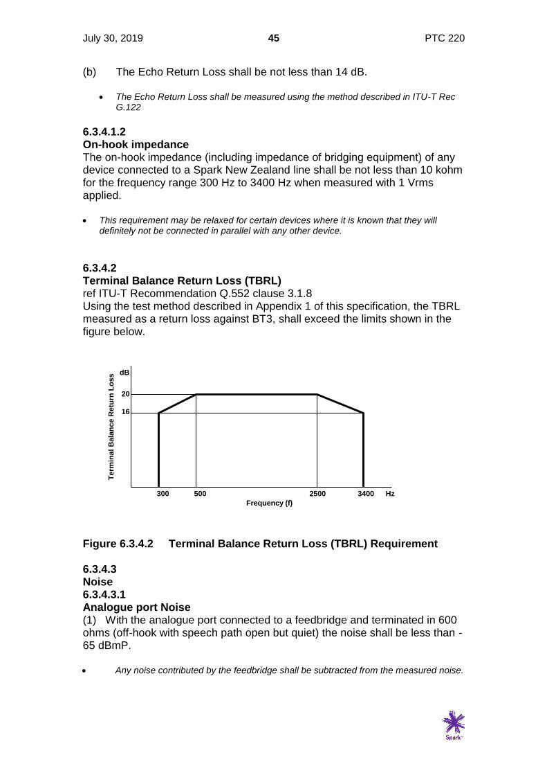
6.3.4.2 Terminal Balance Return Loss (TBRL) ref ITU-T Recommendation Q.552 clause 3.1.8 Using the test method described in Appendix 1 of this specification, the TBRL measured as a return loss against BT3, shall exceed the limits shown in the figure below.
Figure 6.3.4.2 Terminal Balance Return Loss (TBRL) Requirement 6.3.4.3 Noise 6.3.4.3.1 Analogue port Noise (1) With the analogue port connected to a feedbridge and terminated in 600 ohms (off-hook with speech path open but quiet) the noise shall be less than -65 dBmP. • Any noise contributed by the feedbridge shall be subtracted from the measured noise.
300 500 2500 3400
16
20
dB
Hz
Frequency (f)
Te
rmin
al
Bala
nc
e R
etu
rn L
os
s
July 30, 2019 46 PTC 220
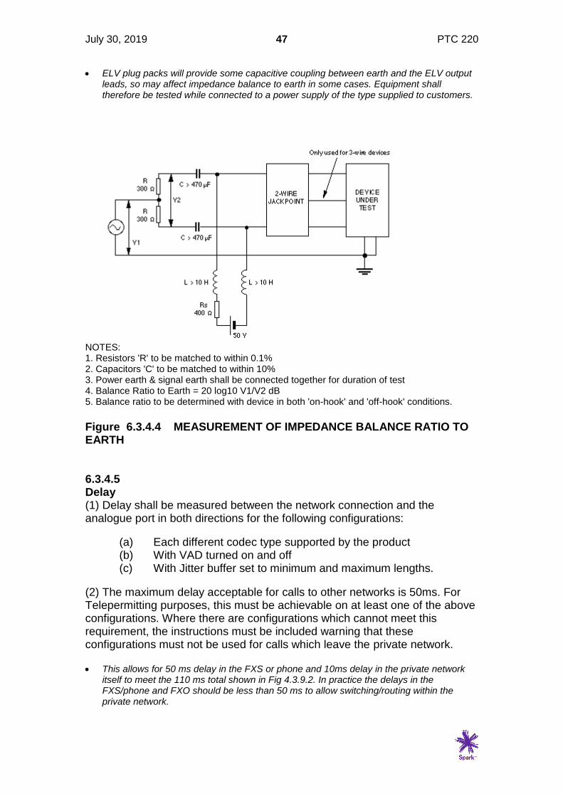
(2) With the analogue port terminated in 10 kohms (on-hook) the noise shall be less than -65 dBmP (3) The noise in any 3kHz bandwidth above 4kHz shall be below lines joining the points given in table 5.3.4.4. FREQUENCY POWER SPECTRAL DENSITY (kHz) (dBm) 4.0 -40 10.0 -40 20.0 -50 50.0 -70 >50.0 & <100.0 -70 >100.0 & <10 MHz -50 Table 5.3.4.4 limits for noise above 4kHz on FXO port 6.3.4.3.2 Crosstalk between Ports Where FXO equipment has more than one analogue port there shall be a minimum of 50 dB isolation between individual ports over the range 300 - 3400 Hz. This shall apply to both on-hook and off hook conditions. 6.3.4.4 Impedance balance ratio to earth (1) Devices which have a direct or indirect connection to earth shall, for both on-hook and off-hook conditions, have an impedance balance ratio to earth of not less than 40 dB over the frequency range 200 - 4000 Hz when tested as shown in Fig. 6.3.4.4. (2) It is strongly recommended that, in the off-hook condition, devices should also have an impedance balance ratio to earth of not less than 60 dB over the frequency range 200 - 1000 Hz. (3) Equipment connected directly or indirectly to mains power supplies shall also comply with the requirements of this clause.
July 30, 2019 47 PTC 220
• ELV plug packs will provide some capacitive coupling between earth and the ELV output leads, so may affect impedance balance to earth in some cases. Equipment shall therefore be tested while connected to a power supply of the type supplied to customers.
NOTES: 1. Resistors 'R' to be matched to within 0.1% 2. Capacitors 'C' to be matched to within 10% 3. Power earth & signal earth shall be connected together for duration of test 4. Balance Ratio to Earth = 20 log10 V1/V2 dB 5. Balance ratio to be determined with device in both 'on-hook' and 'off-hook' conditions.
Figure 6.3.4.4 MEASUREMENT OF IMPEDANCE BALANCE RATIO TO EARTH 6.3.4.5 Delay (1) Delay shall be measured between the network connection and the analogue port in both directions for the following configurations:
(a) Each different codec type supported by the product (b) With VAD turned on and off (c) With Jitter buffer set to minimum and maximum lengths.
(2) The maximum delay acceptable for calls to other networks is 50ms. For Telepermitting purposes, this must be achievable on at least one of the above configurations. Where there are configurations which cannot meet this requirement, the instructions must be included warning that these configurations must not be used for calls which leave the private network. • This allows for 50 ms delay in the FXS or phone and 10ms delay in the private network
itself to meet the 110 ms total shown in Fig 4.3.9.2. In practice the delays in the FXS/phone and FXO should be less than 50 ms to allow switching/routing within the private network.
July 30, 2019 48 PTC 220
6.3.4.6 Codec Type All FXO equipment shall have a G.711 codec. Other codecs may also be used, but cannot be tested using conventional test techniques. A list of all codecs used and the method of implementing them shall be provided. This includes information as to whether the codec is fixed as part of the initial system set-up, or is selected dynamically on a call by call basis depending on the call destination or other parameters. 6.3.4.7 Echo (1) Where the mean one way propagation time exceeds 15ms echo cancellers should be deployed. VoIP and wireless technologies are likely to have inherent delays exceeding 15ms and would be expected to have echo cancellers fitted. Assuming echo cancellers are fitted, values of 65dB and 110dB are used for TELR and WEPL respectively in calculating the delay impairment factor Id. (2) The configuration and parameters of an echo canceller shall be stated if used in the FXO. 6.4 Signalling 6.4.1 Transmission of DTMF signalling • Reference CCITT Blue Book, Recommendation Q. 23.
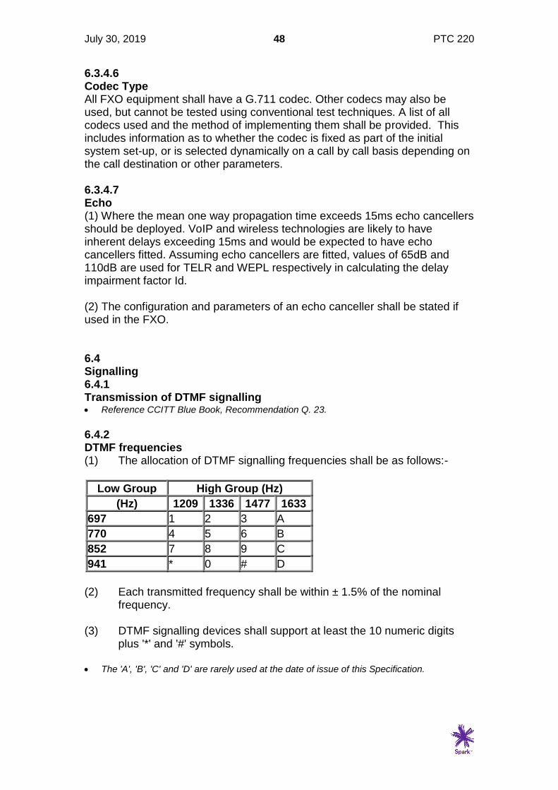
6.4.2 DTMF frequencies (1) The allocation of DTMF signalling frequencies shall be as follows:-
Low Group High Group (Hz)
(Hz) 1209 1336 1477 1633
697 1 2 3 A
770 4 5 6 B
852 7 8 9 C
941 * 0 # D
(2) Each transmitted frequency shall be within ± 1.5% of the nominal
frequency. (3) DTMF signalling devices shall support at least the 10 numeric digits
plus '*' and '#' symbols. • The 'A', 'B', 'C' and 'D' are rarely used at the date of issue of this Specification.
July 30, 2019 49 PTC 220
6.4.3 DTMF signalling requirements (1) For optimum performance, all transmitted DTMF frequencies shall
comply with the requirements of this Specification at all line currents in the range 20 mA to full current.
• Full current is defined as the current drawn by the FXO port when connected to a 50V + 400 Ohm feedbridge
(2) All devices shall satisfy the following requirements during the
transmission of DTMF signalling:-
(a) While DTMF signals are being transmitted during the setting-up of a call, the minimum return loss against BT3 shall be no less than 5 dB.
• This relaxation does not apply to the transmission of DTMF signals following
establishment of the call, e.g. signalling CPE to CPE.
(b) Each individual signalling tone of a burst, when measured against 600 ohm on a zero length line, shall be at a power level between -4 dBm and -13 dBm.
(c) For successful operation of DTMF signalling between customer premises, it is recommended that DTMF send levels be in the range -4 dBm to -10 dBm.
(d) There shall be a pre-emphasis in the range 1 to 3 dB for the high frequency tone group relative to the low frequency group. (e) During signalling (call set-up phase for all devices):-
(i) The individual power level of any extraneous frequency in the
range 300 Hz to 5 kHz during signalling shall be at least 20 dB below that of the signalling frequency with the lowest level.
(ii) The one minute mean power level in any 3 kHz bandwidth
contained wholly above 5 kHz shall be at least 20 dB below that of the signalling frequency with the lowest level.
• "Noise" includes any unwanted signals such as distortion and intermodulation products
that may occur during call set-up signalling.
6.4.4 Signal timing The duration of transmitted DTMF signals shall comply with the following requirements: - (a) The minimum valid tone duration shall be 60 ms, and the minimum
inter- digital pause shall also be 60 ms, exclusive of any rise and fall times.
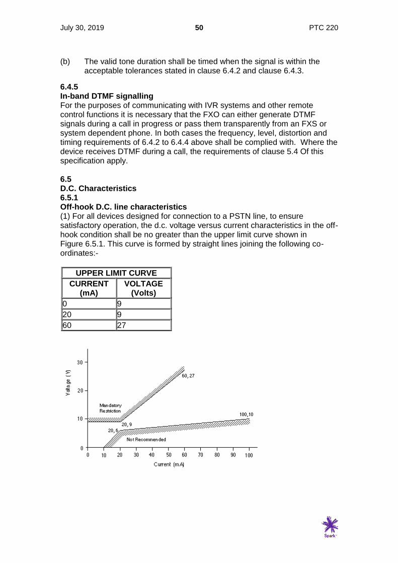
July 30, 2019 50 PTC 220
(b) The valid tone duration shall be timed when the signal is within the
acceptable tolerances stated in clause 6.4.2 and clause 6.4.3.
6.4.5 In-band DTMF signalling For the purposes of communicating with IVR systems and other remote control functions it is necessary that the FXO can either generate DTMF signals during a call in progress or pass them transparently from an FXS or system dependent phone. In both cases the frequency, level, distortion and timing requirements of 6.4.2 to 6.4.4 above shall be complied with. Where the device receives DTMF during a call, the requirements of clause 5.4 Of this specification apply. 6.5 D.C. Characteristics 6.5.1 Off-hook D.C. line characteristics (1) For all devices designed for connection to a PSTN line, to ensure satisfactory operation, the d.c. voltage versus current characteristics in the off-hook condition shall be no greater than the upper limit curve shown in Figure 6.5.1. This curve is formed by straight lines joining the following co-ordinates:-
UPPER LIMIT CURVE
CURRENT (mA)
VOLTAGE (Volts)
0 9
20 9
60 27

July 30, 2019 51 PTC 220
FIG. 6.5.1 LIMITS OF D.C. CHARACTERISTICS (2) The FXO shall retain its full capability with a line current of 20 mA. 6.5.2 Supervisory Conditions (1) Line seizure: FXO equipment shall initiate an outgoing call by going off-hook and drawing d.c. line current from the PSTN line. (2) Ring trip: FXO equipment shall answer an incoming call (on receipt of incoming ringing), by going off-hook and drawing d.c. line current from the PSTN line. (3) Call release: The FXO equipment shall terminate a call by going on-hook and breaking the line current. At this point it shall be ready to receive a subsequent incoming call. (4) To ensure satisfactory performance of each of these supervisory functions, the device shall satisfy the mandatory requirements given in clause 6.5. • An increasing number of line feeds have limited current sources (such as those provided
by "derived circuit" equipment and many PABX's). For this reason it is not permitted to have customer equipment incorporating constant current sinks as a means of holding the line in a seized condition. This is reflected in the d.c. characteristic upper limit curve having a finite slope from the 20 mA minimum rather than a vertical constant current characteristic.
(5) FXO equipment shall automatically release any call in progress within 5 seconds of failure of its power source. 6.5.3 Line breaks The duration of any undefined interruption or random break in the d.c. path caused by the equipment shall not exceed 9 ms. 6.5.4 On-hook line current In the on-hook state the direct current drawn from a nominal 50 V supply by the FXO equipment shall be not greater than 120 µA. 6.5.5 Recall and call waiting (1) The recall facility is in the form of a timed break in the holding loop condition during a call, and it is known as "timed-break recall" or "TBR". (2) Where provided, the TBR of customer products shall be within the range 500 ms to 800 ms. If a product cannot be set to operate within this range then the TBR function shall be disabled. Also, a suitable explanation shall be inserted in the User Instructions advising users that the facility is not available.
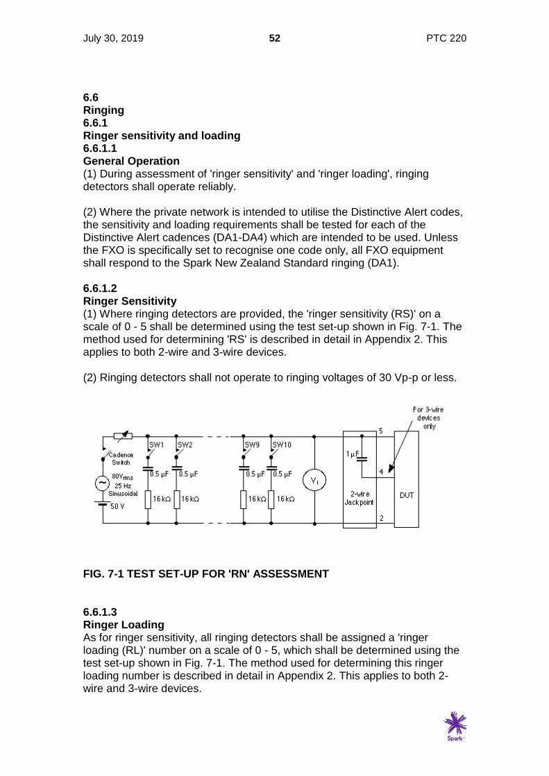
July 30, 2019 52 PTC 220
6.6 Ringing 6.6.1 Ringer sensitivity and loading 6.6.1.1 General Operation (1) During assessment of 'ringer sensitivity' and 'ringer loading', ringing detectors shall operate reliably. (2) Where the private network is intended to utilise the Distinctive Alert codes, the sensitivity and loading requirements shall be tested for each of the Distinctive Alert cadences (DA1-DA4) which are intended to be used. Unless the FXO is specifically set to recognise one code only, all FXO equipment shall respond to the Spark New Zealand Standard ringing (DA1). 6.6.1.2 Ringer Sensitivity (1) Where ringing detectors are provided, the 'ringer sensitivity (RS)' on a scale of 0 - 5 shall be determined using the test set-up shown in Fig. 7-1. The method used for determining 'RS' is described in detail in Appendix 2. This applies to both 2-wire and 3-wire devices. (2) Ringing detectors shall not operate to ringing voltages of 30 Vp-p or less.
FIG. 7-1 TEST SET-UP FOR 'RN' ASSESSMENT 6.6.1.3 Ringer Loading As for ringer sensitivity, all ringing detectors shall be assigned a 'ringer loading (RL)' number on a scale of 0 - 5, which shall be determined using the test set-up shown in Fig. 7-1. The method used for determining this ringer loading number is described in detail in Appendix 2. This applies to both 2-wire and 3-wire devices.
July 30, 2019 53 PTC 220
6.6.2 Ringing Number (RN) (1) The ringing number (RN) allocated shall be in the range 0.5 - 5 and shall be equal to the higher of the following: - (a) Ringer sensitivity number (ref clause 6.6.1.2). (b) Ringer loading number (ref clause 6.6.1.3). (2) If the RN derived as above equates to zero, then it shall be rounded up to 0.5. • Spark New Zealand reserves the right to increase the value of 'RN' above that derived in
(1) and (2) if other factors, such as excessive 'on-hook d.c.', indicate the need. However, this is expected to occur in only rare and exceptional cases.
(3) For correct operation, the total of the RN's of all devices connected to a PSTN line at any given time should not exceed 5. • Note that the RN assessment is not intended to be an accurate measurement, but is
primarily a simple guide to customers as to the total number of items they may connect to a line.
(4) Where equipment is not intended to be connected to a line in parallel with other terminal equipment, this shall be clearly stated in the user instructions. • Some items of series connected equipment do not normally have other devices
connected in parallel with their PSTN line port. In cases where this possibility is envisaged, then the factors influencing the RN should be considered in the design.
6.7 Physical Connection There are no specific requirements for the connection of FXO equipment to the network. It is expected that such equipment will be professionally installed, and appropriate connection methods will be used. 6.8 Supplementary Services 6.8.1 Switch-hook Flash Switch-hook flash is the mechanism by which access to supplementary services such as call waiting and three way calling is achieved. The timing for switch-hook flash is given in clause 6.5.5 of this Specification. 6.8.2 Caller ID 6.8.2.1 General (1) Analogue CLI equipment designed for the Spark New Zealand 'Caller Display' service uses the on-hook data transmission facilities described in Technical Document TNA 102, Sections 10 and 11.
July 30, 2019 54 PTC 220
6.8.2.2 On-hook impedance (1) During the reception of data the receiver of an on-hook device may, for the purpose of improving impedance matching, terminate the line with a more suitable a.c. impedance (e.g. BT3) than that stated in clause 6.3.4.1.2 of this Specification. In this case the following shall apply:- (a) This impedance shall be removed either when the second ring cadence occurs (preferably just before), or when another device on the same line goes off-hook. (b) If coded ringing is implemented on the same line, the unit shall also decode the ringing to determine when the impedance should be applied and removed. • There is potential for confusion between DA2 and DA4 because of the extended silent
period between the first two bursts of ringing.
• The difference should be noted between the standard Spark New Zealand off-hook impedance BT3 (ref clause 4.5.1) and the 600 ohm plus 2.16 µF series network commonly used on North American products. However, it is not anticipated that this difference will cause any problems for on-hook data transmission.
(2) At all other times, the on-hook impedance shall be as stated in clause 6.3.4.1.2 of this Specification. 6.8.2.3 Data capture (1) The receivers of all devices which use on hook data transmission shall be capable of receiving data in the format described in Technical Document TNA 102, Section 10. Both single data message format (SDMF) and multiple data message format (MDMF) shall be supported. (2) Receivers should be capable of receiving data during any of the four ringing cadences used (see clause 11.4.3(a) above). If not, a suitable warning shall be included which clearly explains to the customer which DA codes the device is compatible with. Fig. 11-3 illustrates the timing requirements for analogue CLI devices with respect to the different DA codes. • It should be noted that the data is limited to 'Time/Date', Area code and 'Directory
Number' when sent with DA3 and DA4 cadences.
(3) Receivers shall perform satisfactorily when connected via a zero, 3 km and 6 km artificial line (see Fig. 4-1(b) in Section 4). In each case the test shall be carried out with and without a ringer built out to a RN of 5 (ref. Section 7) connected in parallel. The ringer shall remain operational for all the tests in which it is connected. (4) All messages that contain corrupted data, as indicated by an incorrect checksum, shall be discarded.

July 30, 2019 55 PTC 220
(5) It is recommended that the receiver functions should be independent of the exact length of the CSS and pre-message mark signal.
• These are not included in the checksum and do not carry any information except to function as a 'wake up' signal.
Notes: *1 10 bits per character, 1200 bps *3 Overhead for MDMF Message Type - 1 Character Message Length - 1 Character *2 Overhead for SDMF: Date/Time Parameter Type - 1 Character Message Type - 1 Character Date/ Time Parameter Length - 1 Character Message length - 1 Character Date/Time - 8 Characters Date/Time - 8 Characters Directory Number Parameter Type - 1 Character
Directory Number - X Characters Directory Number Parameter Length
- 1 Character
Checksum - 1 Character Directory Number - X Characters Name Parameter Type - 1 Character Total Characters = 11 + X Name Parameter Length - 1 Character Name - Y Characters Checksum - 1 Character Total Characters = 17 + X + Y FIG. 11-3 TIMING DIAGRAM FOR ANALOGUE CALLING LINE IDENTIFICATION SIGNALS 6.8.2.4 Number format passed from the network (1) For local and national calls, the number sent forward from the Spark New Zealand network is in the format "area code" plus "customer number". No "0" national call prefix is passed forward from the network.
July 30, 2019 56 PTC 220
• This is the format used within the Spark New Zealand network and between New Zealand networks for passing calling numbers. For such applications, the "0" has no meaning.
• Display equipment designers should note that there is no format differentiation between national and local calls.
(2) For incoming international calls entering New Zealand via a Spark New Zealand International Exchange, the digits "0000" are currently passed forward. This will continue to be the practice for any international numbers that are either not available or need to be withheld in the future for any reason. • The actual numbers are currently withheld to protect the privacy of overseas callers.
• It should be noted that not all international calls arrive in New Zealand via the Spark New Zealand Gateway. Many arrive via other carriers.
(3) In due course, some international numbers are expected to be made available to New Zealand customers. Where such numbers are available for presentation, the number sent forward from the Spark New Zealand network will be in the format "country code" plus "area code" plus "customer number". No "00" international call prefix will be passed forward from the network. As a result, there could be confusion between national and international numbers on display units. • When international numbers are available for presentation to New Zealand customers,
the number length may be any length up to 15 digits. See warning note on clause 11.4.6.
• The timing for such a service introduction is unknown at this stage.
(4) For incoming calls wholly within a Centrex group, the number passed forward will be the extension number used within that Centrex customer's network. The number length will be within the range of 2 to 7 digits. (5) The number actually passed from the network may not relate to a specific person or line. • For example, where the pilot number of a DDI PABX group is passed forward, a display
user dialling that number is likely to reach the PABX operator, not the person who originally made the call. Similarly, a small percentage of displayed numbers may not correspond with a number that can be called back.
6.8.3 Distinctive alert ringing A private network which extends Distinctive alert ringing cadences from the PSTN to the FXS port shall meet the requirements of clause 6.6 of this specification and reproduce the correct cadences at the FXS port. See also section 5.
July 30, 2019 57 PTC 220
6.8.4 Fax/Voice band modem transport If the FXO equipment is connected to the FXS by either low bit rate transmission, or via packets such as IP, voiceband data such as fax or V.92 modems may not operate at full speed, or may not operate at all. If special measures are taken to enable voiceband data to be transported these shall be noted. See clause 6.9.4 for functional test. • The normal method of dealing with voiceband data is to demodulate the analogue
signals, transport them as data, and re-modulate them at the FXS/FXD for passing onto the PSTN/ISDN.
6.8.5 Incoming Call DDI Where the FXO supports incoming call DDI, it shall meet the requirements of PTC107. 6.9 Functional requirements 6.9.1 General This Section covers the functional requirements for FXO equipment. Many of these requirements depend on compatible FXS equipment or system dependent phones, and tests shall be performed with such suitable equipment. Telepermits will be granted to FXO equipment subject to use with the FXS equipment/phone with which it was tested or equipment with equivalent functionality. It is the responsibility of the Telepermit holder to ensure that alternative FXS equipment/phones are not only Telepermitted but have also been thoroughly checked against the functional requirements of this specification. 6.9.2 Call Set-up (outgoing call) 6.9.2.1 Signalling (1) When a number is dialled from the FXS or phone, the FXO shall seize the line and commence dialling within 2 seconds of the last number being either received from CPE connected to the analogue port of the FXS equipment or a system specific phone. This time includes a minimum 1 second pause between seizing the line and the commencement of dialling where no dial tone detection is provided. • Refer PTC200 clause 8.1.2
(2) If the FXO waits for the last digit to be dialled before seizing the line, it requires prior knowledge of the number length, or imposition of very short interdigit timeout. An alternative is to seize the line and begin dialling as the first digit is received, or even when the CPE initiating the call goes off-hook. The FXO must then check the network for NU tone which indicates that either a non-existent number has been dialled, or the interdigit pause is too long.
July 30, 2019 58 PTC 220
The NU tone or other suitable indicator shall be sent from the FXO to the FXS or phone.
(3) The correct number shall be dialled from the FXO network connection.
6.9.2.2 Call progress indicators The following call progress indicators shall be either recognised by the FXO and indicators sent to the FXS equipment or phone where suitable indicators shall be regenerated, or an audio path shall be maintained from the FXO during call set-up.
(1) Ringing tone (as an indication that the called party phone is ringing)
(2) Busy Tone (as an indication that the called party is busy)
(3) Recorded Announcement (used to indicated a variety of conditions from the network)
(4) Disconnect tone (to indicate that the other party has hung up)
(5) NU (to indicate that the number dialled does not currently exist)
(6) Network congestion tone (to indicate that the network cannot complete the call at that time)
• Tones can be transmitted reliably over a link using ITU-T C.711 codecs, but not necessarily over a link using some low bit rate codecs which are optimised for human voice characteristics.
• The tones used on the Spark New Zealand Network are detailed in TNA 102.
6.9.2.3 Call connect A both-way audio connection shall be established within 200ms of cessation of ringing tone.
6.9.2.4 Call clear (1) If a call is aborted during setup, the FXO shall clear down any network connection within 5 seconds.
(2) If the PSTN times out during call setup and returns NU tone, then the FXO shall send an indication to the FXS equipment or phone, and clear the PSTN connection 6.9.2.5 Call in progress (1) Both-way audio connection shall be maintained until one or other party clears the call.
(2) While a call is in progress, DTMF tones received from the PSTN shall be forwarded to the FXS equipment or phone
July 30, 2019 59 PTC 220
(3) While a call is in progress, DTMF tones received by the FXS equipment from CPE connected to its analogue port or DTMF tones generated by a system phone shall be forwarded to the PSTN. Where the DTMF signals are regenerated in the FXO equipment, they shall meet the requirements given in section 6.4 of this specification.
• Where G.711 codecs are employed, the DTMF can be carried in-band in both directions, but with some low bit rate codecs, it may be necessary to generate the DTMF at both the FXS analogue interface and the FXO network interface.
(4) A Switch hook flash generated by CPE connected to the analogue port of the FXS equipment or from a system phone shall be correctly regenerated at the FXO interface.
6.9.2.6 Call Clear 6.9.2.6.1 Call Clear from private network (a) The FXO shall clear down the call at the interface to the PSTN within 5 seconds of call clear signal indicating that a system phone has gone on-hook, or CPE connected to the analogue port of the FXS equipment has gone on-hook. (b) Where a phone or FXS becomes disabled, by either loss of power or network connection, it will be unable to send a call clear message e.g. a SIP "bye". In this circumstance the FXO will need to implement an activity timeout, and clear the network connection. Ideally this timeout should be reasonably short, particularly if the call is charged by duration. If VAD is not implemented, the cessation of RTP packets can indicate that the terminal has been disconnected or powered down, and the network call shall be terminated within 5 seconds. However, if VAD is implemented there is no way of telling the difference between a long pause in activity or the loss of terminal function. Where VAD is an option there shall be a timeout implemented, and user warnings indicating that chargeable calls could be charged more than expected due to the call being held up by the FXO.
• In practice it will probably be apparent to the party on the other end of the call that the call has become ineffective and they will terminate the call at which time charging will cease.
6.9.2.6.2 Call Clear from PSTN When the PSTN party clears the call, the FXO shall terminate the PSTN connection and send a call clear indication to the FXS equipment or system phone.
July 30, 2019 60 PTC 220
6.9.3 Incoming call from PSTN
(1) Ringing shall be recognised by the FXO equipment and indication sent to the FXS or system phone, so that an alert is presented to the user within 2 seconds of ringing being presented at the FXO interface.
(2) When an answer signal is received from the FXS or system phone, the PSTN connection shall be looped with a d.c. impedance of not more than 1000 ohms and a both-way audio transmission path shall be established.
(3) If Caller ID is implemented, it shall conform to the specifications given in TNA 102 sections 9 and 11.
(4) If DDI is implemented, the call shall be routed to the appropriate FXS port or system phone.
6.9.4 Voiceband Data If the FXS makes special provision for carrying voiceband data, a fax or data call to a compatible modem (fax or data modem) on the PSTN, and receive a data call from a compatible modem on the PSTN.
July 30, 2019 61 PTC 220
7.0 FXD Requirements 7.1 General This Section covers the requirements for a standalone FXD unit for interfacing a private network to a digital PSTN line such as ISDN or E1. 7.1.1 Test Configuration The Test Laboratory shall document in the form of a block schematic, the configuration used for testing this section. This shall include the make and model of the FXS used to complete some of the tests, and state where the TRP is located. • The TRP would normally be at the Ethernet interface to the FXO, or in the case of a
circuit switched PBX at the centre of the switch block.
• Examples of the block schematic are given in the test setups in Appendix 1 of this specification.
7.1.2 Configuration Details Actual setup configurations shall be recorded in the test report for all test results in this section. At least one FXD configuration must be able to achieve compliance for all parts of this specification. 7.2 Electrical Safety The unit shall meet the requirements of AS/NZS 60950. This includes the following FXD components: (a) Power Supply (b) LAN/WAN port(s) isolation to TNV2 7.3 Transmission 7.3.1 FXD Loss Plan (a) Loss from TRP to FXD Digital (ISDN) trunk: 0.5 dB to -0.5 dB,
Objective: 0 dB (b) Loss from FXD Digital (ISDN) trunk to TRP: 0.5 dB to -0.5 dB,
Objective 0 dB 7.3.2 Attenuation Frequency Distortion The loss distortion with frequency between the ISDN/E1 port and the TRP and the TRP and the digital port shall be within the following limits, using an input level of -10 dBm0.

July 30, 2019 62 PTC 220
Frequency Loss relative to the loss at 1000Hz (Hz) (dB) 300 - 400 +1, -0.3 400 - 600 +0.75, -0.3 600 - 2000 +0.35, -0.3 2000 - 2400 +0.45, -0.3 2400 - 3000 +0.7, -0.3 3000 - 3400 +1.7, -0.3 • Reference ITU Recommendation Q.552
7.3.3 Variation of Gain with input level With a 1000 Hz sinewave signal applied to either the ISDN/E1 port 0dBr point at a level between -55 dBm0 and +3 dBm0, the gain of that signal relative to the gain of a signal at an input level of -10 dBm0, shall be within the following limits: Input level Gain Variation (dBm0) (dB) -55 to -50 +/- 1.6 -50 to -40 +/- 0.6 -40 to +3 +/- 0.3 • ITU-T Recommendation Q.552 clause 3.1.1.4
7.3.4 Delay (1) Delay shall be measured between the network connection and the TRP in both directions for the following configurations:
(a) Each different codec type supported by the product (b) With VAD turned on and off (c) With Jitter buffer set to minimum and maximum lengths.
(2) The maximum delay acceptable for calls to other networks is 50ms. For Telepermitting purposes, this must be achievable on at least one of the above configurations. Where there are configurations which cannot meet this requirement, the instructions must be included warning that these configurations must not be used for calls which leave the private network.
• This allows for 50 ms delay in the FXS or phone and 10ms delay in the private network itself to meet the 110 ms total shown in Fig 4.3.9.2. In practice the delays in the FXS/phone and FXO should be less than 50 ms to allow switching/routing within the private network.
7.3.5 Codec Type All FXD equipment shall have a G.711 codec. Other codecs may also be used, but cannot be tested using conventional test techniques. A list of all

July 30, 2019 63 PTC 220
codecs used and the method of implementing them shall be provided. This includes information as to whether the codec is fixed as part of the initial system set-up, or is selected dynamically on a call by call basis depending on the call destination or other parameters.
• In many implementations there will be configurations where the FXD does not use a codec at all. The interface merely reformats a digital voice stream between a packet or TDM format without changing the voice coding at all.
7.3.6 Echo (1) Where the mean one way propagation time exceeds 15ms echo cancellers should be deployed. VoP and wireless technologies are likely to have inherent delays exceeding 15ms and would be expected to have echo cancellers fitted. Assuming echo cancellers are fitted, values of 65dB and 110dB are used for TELR and WEPL respectively in calculating the delay impairment factor Id. (2) The configuration and parameters of an echo canceller shall be stated if used in the FXD. 7.4 Signalling 7.4.1 ISDN ISDN interfaces shall meet the requirements of the following Spark New Zealand Specifications: PTC 131 Basic Rate Access Layer 1 PTC 132 Primary Rate Access Layer 1 TNA 133 Layer 2 TNA 134 Layer 3 The FXD shall map the signalling functions between the private network and the ISDN interfaces in accordance with the following requirements: 7.4.2 Outgoing Calls The FXD may employ either en-bloc or overlap signalling at the ISDN interface. The relationship between the ISDN interfaces when using these signalling modes shall be as follows: 7.4.2.1 En-bloc Signalling The outgoing call set-up sequence shall be in accordance with TNA 134 §C5.1.1, except where modified as follows: When the complete number to be dialled into the ISDN has been received from the FXS or system phone, the FXD shall: (a) send a SETUP message in accordance with TNA 134 C3.1.16 containing the correctly formatted address digits.
July 30, 2019 64 PTC 220
(b) either enable the transmission path in both directions, or send appropriate messages to the FXS/phone for call progress tones to be generated locally consistent with the network messages.
(c) The coding of the Bearer Capability (BC) and where used, High
Layer Compatibility (HLC) and Low Layer Compatibility (LLC) message elements shall be in accordance with TNA 134 §4.5.5, §4.5.16, and §4.5.18 respectively. The Bearer Capability Information Transfer Capability shall be coded 3.1 kHz Audio
(d) The SETUP Message originated from the FXD shall contain
Progress Indicator No 3, "Originating address not ISDN". 7.4.2.2 Overlap Signalling The outgoing call set-up sequences shall be in accordance with TNA 134 C5.1.3 overlap signalling requirements except where modified as follows:
(a) For those cases where call progress tones are generated locally by the FXS/phone, detection of an off-hook condition dial tone should be applied and the FXD shall send a SETUP message (without address information) to the ISDN interface.
For those cases where the FXS/phone does not generate tones locally, on detection of an off-hook condition, the FXD shall cause a SETUP (without address information) to be sent by the ISDN Interface and, when a SETUP ACKNOWLEDGE message is received, enable the transmission path in both directions to and from the B-channel specified in that message. • This is to allow the network tones to be sent in-band to the FXS/phone
• Where appropriate, on receipt of the first address digit on the analogue
interface, the FXS/phone shall cease application of dial tone.
(c) Subject to the requirements of TNA 134, each address digit
received from the FXS/phone shall cause an equivalent address character to be transmitted by the FXD to the ISDN interface in an INFORMATION message.
(d) The coding of the Bearer Capability (BC) and where used, High
Layer Compatibility (HLC) and Low Layer Compatibility (LLC) message elements shall be in accordance with TNA 134 §4.5.5, §4.5.16, and §4.5.18 respectively. The Bearer Capability Information Transfer Capability shall be coded 3.1 kHz Audio
(e) The SETUP Message originated from the FXD shall contain
Progress Indicator No 3, "Originating address not ISDN".

July 30, 2019 65 PTC 220
7.4.3 E1 E1 interfaces shall meet the requirements of PTC 107. 7.4.4 SIP Trunking SIP trunk interfaces shall meet the requirements of PTC 229. 7.4.5 In-band DTMF signalling For the purposes of communicating with IVR systems and other remote control functions it is necessary that the FXD can either generate DTMF signals during a call in progress or pass them transparently from an FXS or system dependent phone. 7.4.5.1 DTMF frequencies (1) The allocation of DTMF signalling frequencies shall be as follows: -
Low Group High Group (Hz)
(Hz) 1209 1336 1477 1633
697 1 2 3 A
770 4 5 6 B
852 7 8 9 C
941 * 0 # D
(2) Each transmitted frequency shall be within ± 1.5% of the nominal
frequency. (3) DTMF signalling devices shall support at least the 10 numeric digits
plus '*' and '#' symbols. • The 'A', 'B', 'C' and 'D' are rarely used at the date of issue of this Specification.
7.4.5.2 DTMF signalling requirements (1) All devices shall satisfy the following requirements during the transmission of DTMF signalling: -
(a) Each individual signalling tone of a burst, shall be at a power level between -4 dBm and -13 dBm measured at the PSTN 0 dBr point.
(b) There shall be a pre-emphasis in the range 0 to 3 dB for the high frequency tone group relative to the low frequency group. (c) During signalling:-
July 30, 2019 66 PTC 220
(i) The individual power level of any extraneous frequency in the range 300 Hz to 5 kHz during signalling shall be at least 20 dB below that of the signalling frequency with the lowest level.
(ii) The one minute mean power level in any 3 kHz bandwidth
contained wholly above 5 kHz shall be at least 20 dB below that of the signalling frequency with the lowest level.
• "Noise" includes any unwanted signals such as distortion and intermodulation products
that may occur during call set-up signalling.
7.4.5.3 Signal timing The duration of transmitted DTMF signals shall comply with the following requirements: - (a) The minimum valid tone duration shall be 60 ms, and the minimum
inter- digital pause shall also be 60 ms, exclusive of any rise and fall times.
(b) The valid tone duration shall be timed when the signal is within the
acceptable tolerances stated in clause 7.4.4.1 and clause 7.4.4.2. 7.5 Supplementary services 7.5.1 Switch-hook flash Switch-hook flash is the mechanism by which an analogue phone accesses supplementary services such as call waiting and 3-way calling. An FXS receiving a switch-hook flash will send a message to the FXO/FXD which must then regenerate the signal and pass it to the network. For ISDN connected FXD equipment, the switch-hook flash is implemented by the FXD sending a FEATURE ACTIVATION element with the feature identifier number set to 1, to the ISDN (see PTC134 clause 4.7) 7.5.2 Distinctive Ringing Distinctive ringing may be generated in the FXS or phone as a result of coding in the SIGNAL INFORMATION element in a CENTREX environment (clause 4.5.28) or Multiple Subscriber Number which is described in Part D of TNA 134. 7.5.3 Caller ID Caller ID is described in Part D of TNA 134. 7.5.4 Fax/Voice band modem transport If the FXD equipment is connected to the FXS by either low bit rate transmission, or via packets such as IP, voiceband data such as fax or V.92
July 30, 2019 67 PTC 220
modems may not operate at full speed, or may not operate at all. If special measures are taken to enable voiceband data to be transported these shall be noted. See clause 7.6.4 for functional test. • The normal method of dealing with voiceband data is to demodulate the analogue
signals, transport them as data, and re-modulate them at the FXS/FXD for passing onto the PSTN/ISDN.
7.5.5 Other Supplementary Features There are other supplementary features available on ISDN which do not have direct equivalents on the PSTN. These are described in TNA 134 Part D, and if implemented shall be in accordance with that clause. These may be accessed directly by a system phone, but if an analogue phone is connected to an FXS, then such features could be activated by DTMF tones. 7.6 Functional requirements 7.6.1 General This Section covers the functional requirements for FXD equipment. Many of these requirements depend on compatible FXS equipment or system dependent phones, and tests shall be performed with such suitable equipment. Telepermits will be granted to FXD equipment subject to use with the FXS equipment/phone with which it was tested or equipment with equivalent functionality. It is the responsibility of the Telepermit holder to ensure that alternative FXS equipment/phones are not only Telepermitted but have also been thoroughly checked against the functional requirements of this specification. 7.6.2 Call Set-up (outgoing call) 7.6.2.1 Signalling 1. When a number is dialled from the FXS or phone, the FXD shall complete
signalling the network within 3 seconds of the last digit being received either from CPE connected to the analogue port of the FXS equipment or from a system specific phone.
2. The appropriate number shall be forwarded from the FXD network
connection. 7.6.2.2 Call progress indicators The following call progress indicators shall either: (a) be recognised by the FXD and indicators sent to the FXS equipment or phone where suitable indicators shall be regenerated, or, (b) extend and maintain an audio path from the FXD during call set-up. 1. Ringing tone (as an indication that the called party phone is ringing)
July 30, 2019 68 PTC 220
2. Busy Tone (as an indication that the called party is busy) 3. Recorded Announcement (used to indicated a variety of conditions from
the network) 4. Disconnect tone (to indicate that the other party has hung up) 5. NU (to indicate that the number dialled does not currently exist) 6. Network congestion tone (to indicate that the network cannot complete the
call at that time) • Tones can be transmitted reliably over a link using ITU-T G.711 codecs, but not
necessarily over a link using some low bit rate codecs which are optimised for human voice characteristics.
7.6.2.3 Call connect A both-way audio connection shall be established within 200ms of cessation of ringing tone. 7.6.2.4 Call clear 1 If a call is aborted during setup, the FXD clear down any network connection within 5 seconds. 2 If the PSTN times out during call setup and returns NU tone, then the FXD shall send an indication to the FXS equipment or system phone, and clear the PSTN connection 7.6.2.5 Call in progress 1. Both-way audio connection shall be maintained until one or other party clears the call. 2. While a call is in progress, DTMF tones received from the PSTN shall be forwarded to the FXS equipment or system phone. • This may be as in-band tones or using out of band transmission using IETF RFC 2833 or
equivalent
3. While a call is in progress, DTMF tones received by the FXS equipment from CPE connected to its analogue port or DTMF tones generated by a system phone shall be forwarded to the PSTN. Where the DTMF signals are regenerated in the FXD equipment, they shall meet the requirements given in section 6.4 of this specification. • Where G.711 codecs are employed, the DTMF can be carried in-band in both directions,
but with some low bit rate codecs, it may be necessary to generate the DTMF at both the FXS analogue interface and the FXO network interface.

July 30, 2019 69 PTC 220
4. A Switch hook flash generated by CPE connected to the analogue port of the FXS equipment or from a system phone shall be correctly regenerated at the FXD interface. 7.6.2.6 Call Clear 7.6.2.6.1 Call Clear from private network (a) The FXD shall clear down the call at the interface to the PSTN within 5 seconds of receiving a signal indicating that a system phone has gone on-hook, or CPE connected to the analogue port of the FXS equipment has gone on-hook. (b) Where a phone or FXS becomes disabled, by either loss of power or network connection, it will be unable to send a call clear message e.g. a SIP "bye". In this circumstance the FXD will need to implement an activity timeout, and clear the network connection. Ideally this timeout should be reasonably short, particularly if the call is charged by duration. If VAD is not implemented, the cessation of RTP packets can indicate that the terminal has been disconnected or powered down, and the network call shall be terminated within 5 seconds. However if VAD is implemented there is no way of telling the difference between a long pause in activity or the loss of terminal function. Where VAD is an option there shall be a timeout implemented, and user warnings indicating that chargeable calls could be charged more than expected due to the call being held up by the FXD.
• In practice it will probably be apparent to the party on the other end of the call that the call has become ineffective and they will terminate the call at which time charging will cease.
7.6.2.6.2 Call Clear from PSTN When the PSTN party clears the call, the FXD shall terminate the PSTN connection and send a call clear indication to the FXS equipment or system phone. 7.6.3 Incoming call from PSTN 1. An incoming call from the PSTN shall be recognised by the FXD equipment and indication sent to the appropriate FXS or system phone, so that an alert is presented to the user within 2 seconds of an incoming call being indicated at the FXD interface. 2. When an answer signal is received from the FXS or system phone, a both-way audio transmission path shall be established within 100ms. 3. If Caller ID or distinctive alert is implemented, the correct numbers shall be received by the FXS or system phone or the correct ringing codes shall be regenerated at the FXS or system phone.

July 30, 2019 70 PTC 220
• These functions are not mandatory, but must operate correctly if implemented or have user documentation warnings and instructions for disabling them.
7.6.4 Voiceband Data If the FXS makes special provision for carrying voiceband data, a fax or data call to a compatible modem (fax or data modem) on the PSTN, and receive a data call from a compatible modem on the PSTN.
July 30, 2019 71 PTC 220
8.0 System Specific (including IP) Telephone Requirements 8.1 General (1) This Section covers the requirements for a System Specific Telephone. At some future date, IP phones may be separately specified, when (if) standards evolve. This section also includes "soft" phones where a headset or handset is connected to a PC and the control/ supervisory functions are performed via the PC screen/keyboard/mouse. (2) Where an FXS unit is intended for connection to system dependent phones, the phone and the FXS are tested together as a system dependent phone against the requirements of this section. (3) For standalone headsets, the PTC requirements are documented in PTC 208. 8.1.1 Test Configuration (1) The Test Laboratory shall document in the form of a block schematic, the configuration used for testing this section. This shall include the make and model of the FXO/D or Trunk interface used to complete some of the tests, and state where the TRP is located. • The TRP would normally be at the Ethernet interface to the phone, or in the case of a
circuit switched PBX at the centre of the switch block.
• Examples of the block schematic are given in the test setups in Appendix 1 of this specification.
(2) Where headsets are to be Telepermitted as a standalone item, the associated equipment with which they are tested shall be documented as part of the test report. 8.1.2 Configuration Details (1) Setup configurations shall be recorded for all test results in this section. At least one configuration must be able to achieve compliance for all parts of this specification. 8.2 Other Regulatory Requirements 8.2.1 Electrical Safety The unit shall meet the requirements of AS/NZS 60950. This includes the following FXS components: (a) Power Supply (b) LAN/WAN port(s) isolation to TNV • The power supply used for testing all aspects of this section must be the same as the
power supply marketed with the final Telepermitted product.
July 30, 2019 72 PTC 220
8.2.2 Electromagnetic Compatibility (EMC) The unit shall meet the requirements of AS/NZS CISPR 22 or equivalent. This includes the device itself and any associated power supply. 8.3 Transmission 8.3.1 Loudness Rating (1) Digital phone loudness ratings shall comply with the following limits: (a) SLR to TRP: +5 dB to + 11 dB, Objective: +8 dB (b) RLR from TRP: -1 to + 5 dB, Objective +2 dB (2) The Loudness ratings shall be measured using the method described in ITU-T Recommendations P.64, P.65 and P.79. • See also PTC220 clause 4.3.5.1
• Note that the Loudness Ratings measured at an analogue network interface are higher
(Quieter) than those for a PTC 200 analogue telephone. This is because headsets are usually used in conjunction with private networks, PBX etc, with either zero loss on a digital trunk or low loss on an analogue trunk. For this reason the traffic weighted mean circuit loss of 2.5 dB is included in the loudness rating values.
8.3.2 Side Tone Masking Rating (STMR) The STMR shall be in the range 7 - 25 dB, Objective: 10 - 15 dB Where the STMR is less than 7 dB, the users own voice will sound so loud, that they will tend to lower their voice. If the STMR is greater than 20, the phone sounds dead The STMR shall be measured using the method described in ITU-T Recommendations P.64, P.65 and P.79. 8.3.3 Weighted Terminal Coupling Loss (TCLw) The Terminal Coupling Loss is a measure of the acoustic loss between the earpiece and microphone on a handset. If this loss is too low it will be heard as echo from the party at the other end of the call. The TCLw should be not less than 55 dB (ref ITU-T Rec P.1010) The TCLw shall be measured using the method described in ITU-T Recommendations P.310.
July 30, 2019 73 PTC 220
8.3.4 Frequency response 8.3.4.1 Send Frequency Response The send frequency response, from the Mouth Reference Point (MRP) to the digital interface, shall be within the mask given in Table 8.3.3.1 . • Ref ETSI TBR8 clause 8.2.1.1
Frequency (Hz) Upper limit (dB) Lower Limit (dB) 100 -10 200 0 300 0 -14 1000 0 -8 2000 4 -8 3000 4 -8 3400 4 -11 4000 0 Table 8.3.3.1 Send Frequency response mask • All values are dB on an arbitrary scale
8.3.4.2 Receive Frequency Response The receive frequency response, from the Mouth Reference Point (MRP) to the digital interface, shall be within the mask given in Table 8.3.3.1 . • Ref ETSI TBR8 clause 8.2.1.1
Frequency (Hz) Upper limit (dB) Lower Limit (dB) 100 -6 200 0 300 2 -9 500 * -7 1000 0 -7 3000 4 -7 3400 4 -12 4000 4 Table 8.3.3.2 Receive Frequency response mask * the limit at intermediate frequencies lies on a straight line drawn between the given value on a logarithmic (frequency) - linear (dB) scale • All values are dB on an arbitrary scale
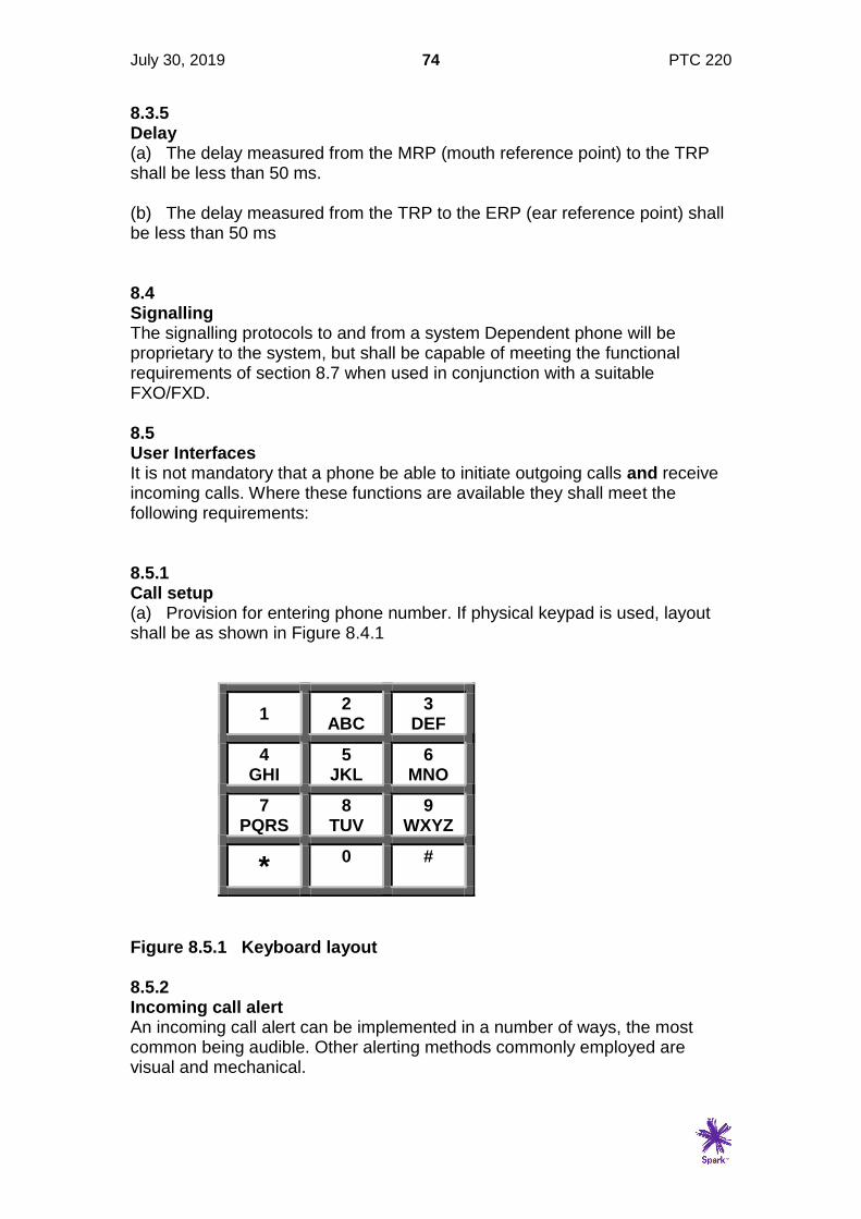
July 30, 2019 74 PTC 220
8.3.5 Delay (a) The delay measured from the MRP (mouth reference point) to the TRP shall be less than 50 ms. (b) The delay measured from the TRP to the ERP (ear reference point) shall be less than 50 ms 8.4 Signalling The signalling protocols to and from a system Dependent phone will be proprietary to the system, but shall be capable of meeting the functional requirements of section 8.7 when used in conjunction with a suitable FXO/FXD. 8.5 User Interfaces It is not mandatory that a phone be able to initiate outgoing calls and receive incoming calls. Where these functions are available they shall meet the following requirements: 8.5.1 Call setup (a) Provision for entering phone number. If physical keypad is used, layout shall be as shown in Figure 8.4.1
1 2
ABC 3
DEF
4 GHI
5 JKL
6 MNO
7 PQRS
8 TUV
9 WXYZ
* 0
#
Figure 8.5.1 Keyboard layout 8.5.2 Incoming call alert An incoming call alert can be implemented in a number of ways, the most common being audible. Other alerting methods commonly employed are visual and mechanical.
July 30, 2019 75 PTC 220
8.5.2.1 Alerting Characteristics (1) The sound level for audible operation of a ringing detector, if provided, shall be at least 50 dBA when measured at 1 metre from the ringer in any direction while it is mounted on a hard surface. • It is recommended that a ringer be capable of producing a minimum acoustic level of 75
dBA. However, this is not mandatory.
(2) There are no further requirements (e.g. frequency) specified for the audible characteristics. • The nature of the sound output signal and the frequency (or frequencies) used are
regarded as marketing features.
(3) There are no specific requirements for visual or mechanical alerting characteristics. 8.6 Physical Connection Details of the method of physical connection shall be provided. It is expected that these will be compatible with standard wiring practices and will be via either an RJ45 or BT plug. 8.7 Functional requirements 8.7.1.1 General This Section covers the functional requirements for system dependent phones. Many of these requirements depend on compatible FXO/FXD equipment, and tests shall be performed with such suitable equipment. Telepermits will be granted to a system phone subject to use with the FXO/FXD equipment with which it was tested or equipment with equivalent functionality. It is the responsibility of the Telepermit holder to ensure that suppliers and system integrators are aware of suitable such equipment. 8.7.2 Call Set-up (outgoing call) 8.7.2.1 Pre-dial Supervisory Tone (Dial Tone) The provision of dial tone is optional. 8.7.2.2 Signalling When a number is dialled from a system phone the appropriate number shall be dialled via the FXS/FXO network connection. 8.7.2.3 Call progress indicators The following call progress indicators shall be presented to the user within five seconds of either the last digit being dialled or a send button or equivalent
July 30, 2019 76 PTC 220
being activated. This will generally be tones presented to the user interface (handset, headset or loudspeaker) or could be via a visual display. The form of these indicators shall be recorded (frequency/ cadence for audio indicators, message or visual display for visual indicators). (1) Ringing (as an indication that the called party phone is ringing) (2) Busy (as an indication that the called party is busy) (3) Recorded Announcement (used to indicated a variety of conditions from the network) (4) Disconnect (to indicate that the other party has hung up) (5) NU (to indicate that the number dialled does not currently exist) (6) Network congestion (to indicate that the network cannot complete the call at that time) 8.7.2.4 Call connect A both-way audio connection shall be established within 200ms of cessation of the ringing indicator. 8.7.2.5 Call clear If a call is aborted during setup, the FXO/FXD shall clear down any network connection within 5 seconds. 8.7.2.6 Call in progress (1) Both-way audio connection shall be maintained until one or other party clears the call. (2) While call is in progress, keys pressed (or otherwise activated) on the dial pad shall cause the correct DTMF signal to be forwarded to the PSTN/ISDN at the FXO/FXD. • Where G.711 codecs are employed, the DTMF can be carried in-band in both directions,
but with some low bit rate codecs, it may be necessary to generate the DTMF at the FXO/FXD network interface.
(3) A Switch hook flash initiated at the system phone shall be correctly regenerated at the FXO/FXD interface. 8.7.2.7 Call Clear 8.7.2.7.1 Call Clear from System Phone The FXO/FXD shall clear down the call at the interface to the PSTN/ISDN within 5 seconds of the system phone clearing the call.
July 30, 2019 77 PTC 220
8.7.2.7.2 Call Clear from other party (from the PSTN/ISDN) When the other party clears the call, some form of indication should be provided at the system phone so that the user is aware that the call has terminated. • This clause is not mandatory, but desirable, particularly if voice activity detection is used,
in which case there may be no indication at all that the call has been cleared.
8.7.3 Incoming call (from PSTN/ISDN via gateway to system phone) (1) Indication (audible ringing, visual or mechanical) shall occur within 5 seconds of the indication being sent to the FXO/FXD interface from the PSTN. (2) Incoming call alert shall cease, and a both-way audio transmission path shall be established within 100ms of the user answering the call. (3) If Caller ID is implemented, the correct originating number shall be displayed.
July 30, 2019 78 PTC 220
9 Voice Mail System Requirements 9.1 General This section covers the requirements for a voice mail module integrated into a private voice network. • See Figure 3.1 for block diagram of showing the architecture of a private network with a
voice mail system.
9.1.1 Test Configuration The Test Laboratory shall document in the form of a block schematic, the configuration used for testing this section. This shall include the make and model of the FXO/D or Trunk interface used to complete some of the tests, and state where the TRP is located. • The TRP would normally be at the Ethernet interface to the phone, or in the case of a
circuit switched PBX at the centre of the switch block.
• Examples of the block schematic are given in the test setups in Appendix 1 of this specification.
9.1.2 Configuration Details Setup configurations shall be recorded for all test results in this section. At least one configuration must be able to achieve compliance for all parts of this specification. 9.2 Electrical Safety The voicemail unit shall meet the requirements of AS/NZS 60950. This includes the following components: (a) Power Supply (b) LAN/WAN port(s) isolation to TNV 9.3 Transmission 9.3.1 Loss Plan In a fully digital network, the loss from the TRP to the voice storage medium and replayed back to the TRP should be zero. However as the actual level at which messages will be recorded will vary with the length of the originating analogue access line, automatic gain control may be used so that recorded messages are replayed to the TRP at similar levels to pre-recorded messages and prompts. (a) Loss from TRP to voice storage medium and replayed back to TRP:
0.5 dB to -0.5 dB, Objective: 0 dB
July 30, 2019 79 PTC 220
(b) If AGC is used, the playback level for voice to the TRP is -12 to 18 VU. Objective -15 VU and for pre-recorded music at the TRP shall be -15 to -24VU.
• There is no objective level for music as it will vary with the type of music recorded. It is recommended that provision for subjective testing and adjustment is available.
• This clause also applies to music on hold facilities.
9.3.2 Recorded message quality (1) The speech quality of any recorded message transmission shall be suitably intelligible to the party on the other end of the call. (2) Overall speech quality will be assessed subjectively by the testing authority and, in any cases of doubt, finally assessed by Access Standards at the time of application. • A suitable quantitative means of assessment may be introduced at some future date.
• Quantitative or subjective 'mean opinion score' assessment of speech quality is extremely complex and would be costly to the applicant. For this reason, no formal qualitative requirement is stated in this Specification.
(3) Spark New Zealand reserves the right to re-assess the quality of the recorded speech transmission of any product after the grant of a Telepermit if there is evidence of substantial complaints from customers. (4) If, during such a re-assessment, it is suitably established that the transmitted speech quality is unintelligible to another party when connected via the Spark New Zealand PSTN, then either:- (a) the speech quality shall be improved to the satisfaction of Spark New Zealand, or (b) the Telepermit will be cancelled. (5) The cost of such re-assessment shall be borne by the Telepermit holder. Also, any cost incurred by Spark New Zealand for investigation of complaints by customers relating to transmitted speech quality may be passed on to the customer using the transmitting device.
July 30, 2019 80 PTC 220
10 Interactive Voice Response Systems 10.1 General This section covers the requirements for Interactive Voice Response (IVR) systems integrated into a private voice network • See Figure 3.1 for block diagram of showing the architecture of a private network with a
voice mail system. An Interactive Voice Response system would occupy the same position in the general architecture.
• An IVR system may not be associated with a private network, and may connect directly to a public interface to the PSTN (digital or analogue). In this case the TRP may not be accessible, and the transmission parameters of Section 11 apply.
10.1.1 Test Configuration The Test Laboratory shall document in the form of a block schematic, the configuration used for testing this section. This shall include the make and model of the FXO/D or Trunk interface used to complete some of the tests, and state where the TRP is located. • The TRP would normally be at the Ethernet interface to the phone, or in the case of a
circuit switched PBX at the centre of the switch block.
• Examples of the block schematic are given in the test setups in Appendix 1 of this specification.
10.1.2 Configuration Details Setup configurations shall be recorded for all test results in this section. At least one configuration must be able to achieve compliance for all parts of this specification. 10.2 Electrical Safety The voicemail unit shall meet the requirements of AS/NZS 60950. This includes the following components: (a) Power Supply (b) LAN/WAN port(s) isolation to TNV 10.3 Transmission 10.3.1 Level Plan 10.3.1.1 Receive levels There are two inputs which an IVR may respond to: Firstly voice signals which may either be stored or used as commands, and secondly DTMF signals which are used as commands, or can be used to enter data. The requirements for sensitivity for receive levels are as follows:
July 30, 2019 81 PTC 220
(a) Voice The IVR system shall respond to voice signals in the range -20 to -6VU measured at the TRP.
• This is the range of signals which can be expected to be received from the network where the originator is on an analogue phone over a range of distances from the local exchange
(b) DTMF The IVR system shall reliably detect and respond to DTMF signals provided the following conditions are met. (a) Any receive level between -5 dBm and -20 dBm. (b) High frequency pre-emphasis of between 0 and 3 dB. (c) DTMF frequencies within ±1.8 % of the nominal values (ref. PTC200
clause 5.2.1(1)). (d) The receiver shall recognise any valid DTMF signal that is present for a
minimum duration as specified in ITU-T Q.24 (NTT option), as long as it is preceded by a continuous pause of 60 ms.
(e) The receiver shall ignore breaks of up to 15 ms provided the signal
either side of the break represents the same digit, and the break does not occur within 20 ms of the start or the finish of the tone burst.
The following DTMF signals shall be rejected: (a) A signal of less than 20 ms duration (b) A signal of less than -40 dBm
(c) A signal in which either of the individual frequencies deviates by more than +/- 3.5% of the nominal frequencies listed in ITU-T recommendation Q.24.
(d) Signals where any frequencies other than the correct DTMF pair are also present shall be rejected as valid DTMF if the total power of such frequencies is greater than the level of the lowest power valid frequency minus 20 dBm.
10.3.1.2 Transmit levels Recorded voice prompts shall be in the range -18 to -12 VU (objective -15 VU) measured at the TRP. Pre-recorded Music (e.g. music on hold) shall be in the range -24 to -15 VU measured at the TRP.
10.3.2 Recorded message quality The requirements are the same as those for a voice mail system Refer Clause 9.3.2.
July 30, 2019 82 PTC 220
10.4 Out of Band RTP Event (IETF RFC2833/RFC4733) Where the IVR system is connected digitally via a SIP trunking Network Interface it may detect DTMF either by analysing the incoming RTP media packets according to the criteria listed clause 10.3.1.1(b) above or detect and analyse RTP Event packets as described in IETF RFC 2833. While RFC2833 has been superseded by RFC4733, many ATA/FXS functions implement RFC2833, so it is recommended that decoding algorithms assume that functionality. This specification does not at this time describe any algorithm for the analysis of RTP Events, but the following recommendations are suggested:
1. The detector should detect RTP Events only and ignore any in-band DTMF signals.
• This prevents the double digit problem, where some in-band DTMF is sent from the
ATA before the media path is cut and RTP Event packets are sent. Depending on the way the ATA operates, the in band DTMF could be long enough to be legitimate, although the RTP Event should be rejected as it will not be preceded by a 40 ms gap. If the in-band DTMF is less than 20 ms which is more likely, then the in-band and RTP Event should be rejected.
2. Analysing DTMF RTP Events should be performed by analysing the
time stamps on each packet, and then accepting/rejecting on the timing requirements of 10.3.1.1(b). The system is reliant on the far end ATA doing the other analogue analysis correctly.
• See also clause 5.4 of this Specification.

July 30, 2019 83 PTC 220
11 Evaluating the Transmission Parameters of Small Switching Systems using Applied Loudness ratings 11.1 General Some smaller switching systems PBXs/Keyphone systems may use 2 wire switching or other techniques which do not allow access to a TRP. In such systems, the transmission characteristics must be measured across the system as a whole. This adds to the number of measurements which need to be taken because the characteristics from every port to every other port have to be measured. 11.1.1 Test Configuration The Test Laboratory shall document in the form of a block schematic, the configuration used for testing this section.
• Examples of the block schematic are given in the test setups in Appendix 1 of this specification.
11.1.2 Configuration Details Setup configurations shall be recorded for all test results in this section. At least one configuration must be able to achieve compliance for all parts of this specification. 11.2 Electrical Safety The voicemail unit shall meet the requirements of AS/NZS 60950. This includes the following components: (a) Power Supply (b) Trunk port(s) isolation to TNV 11.3 Transmission The following table shows the nominal losses between any two ports on private switched system. The tolerance is generally +/- 3dB although where this leads to port to port losses of less than 2 dB, the additional assessment of clause 11.4 will be required to show that the system remains stable.

July 30, 2019 84 PTC 220
FROM (source)
TO (destination)
Loss (dB) 2-w
extension (0 dB CL)
2-w extension
(2.5dB CL)
2-w trunk
Digital trunk
Digital System
Handset**
2-w extension (0 dB CL)
11.5 9.0 2.5 3.0 RLR=5.0
2-w extension (2.5 dB CL)
9.0 6.5 0* 0.5 RLR=2.5
2-w trunk
2.5 0* -6.5* -6.0* RLR=-4.0
Digital trunk
8.5 6.0 -0.5* 0.0 RLR=2.0
Digital System Handset***
SLR=16.5 SRL=14 SLR=7.5 SLR=8.0 OLR=10
*Scenarios using two-wire trunks where calls are switched back to the PSTN ideally require gain (-ve loss) to meet the transmission requirements of section 4. This leads to a potential for instability, so additional tests required to ensure that the system remains stable under such conditions. **RLR at Handset to be measured from the designated interface to the Handset Earpiece as described in ITU-T Recommendations P64, P76 and P79 ***SLR from Handset to be measured between the Handset Microphone and the designated interface as described in ITU-T Recommendations P64, P76 and P79.
11.4 Stability Test criteria for stability are under development, so pending more rigorous criteria, stability shall be assessed subjectively. 11.5 Attenuation Frequency Distortion The loss distortion with frequency between any two ports shall be within the following limits, using an input level of -10 dBm. Frequency Loss relative to the loss at 1000Hz (Hz) (dB) 300 - 400 +2, -0.6 400 - 600 +1.5, -0.6 600 - 2000 +0.7, -0.6 2000 - 2400 +0.9, -0.6 2400 - 3000 +1.4, -0.6 3000 - 3400 +3.4, -0.6
• This is double the half circuit losses specified in ITU-T Recommendation Q.552
July 30, 2019 85 PTC 220
11.6 Variation of Gain with input level For each combination of ports, with a 1000 Hz sinewave signal applied to one port at a level between -55 dBm0 and +3 dBm0, the gain of that signal relative to the gain of a signal at an input level of -10 dBm0 measured at the other port, shall be within the following limits: Input level Gain Variation (dBm0) (dB) -55 to -50 +/- 3.2 -50 to -40 +/- 1.2 -40 to +3 +/- 0.6 • This is double the half circuit losses specified in TU-T Recommendation Q.552 clause
3.1.1.4
11.7 Analogue Port Input Impedance 11.7.1 The impedance of analogue extension ports shall be measured with a call set up between that port and a trunk port which is terminated in with a BT3 impedance. 11.7.2 The impedance of analogue trunks shall be measured with a call set up between that trunk and an extension port which is terminated in with a BT3 impedance. 11.7.3 The impedance of analogue extension ports shall be measured with a call set up between that port and another extension port which is terminated in with a BT3 impedance. For Telepermit compliance this is measured as a Return Loss against BT3, at the following frequencies: 200, 250, 315, 400, 500, 630, 800, 1000, 1250, 1600, 2000, 3150, 4000 Hz (a) The Return Loss shall not be less than 12dB at any of the above
frequencies. (b) The Echo Return Loss shall be not less than 14 dB. • The ELR shall be calculated according to the method given in ITU-T Recommendation G.122
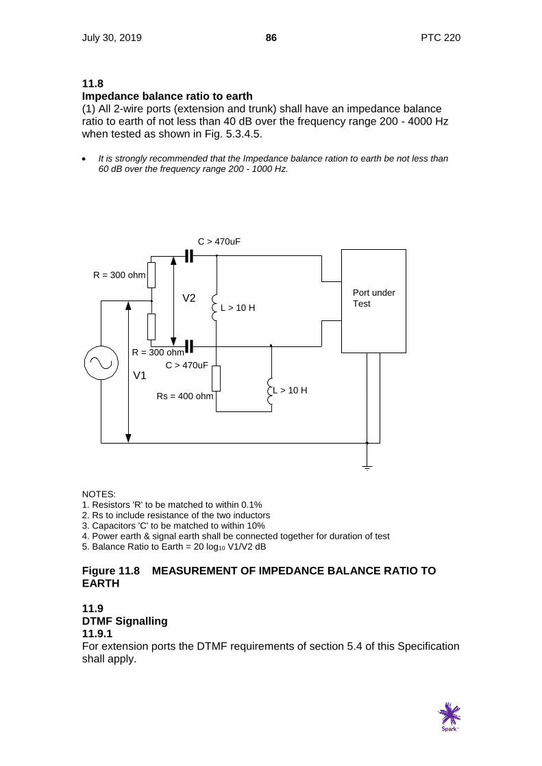
July 30, 2019 86 PTC 220
11.8 Impedance balance ratio to earth (1) All 2-wire ports (extension and trunk) shall have an impedance balance ratio to earth of not less than 40 dB over the frequency range 200 - 4000 Hz when tested as shown in Fig. 5.3.4.5. • It is strongly recommended that the Impedance balance ration to earth be not less than
60 dB over the frequency range 200 - 1000 Hz.
NOTES: 1. Resistors 'R' to be matched to within 0.1% 2. Rs to include resistance of the two inductors 3. Capacitors 'C' to be matched to within 10% 4. Power earth & signal earth shall be connected together for duration of test 5. Balance Ratio to Earth = 20 log10 V1/V2 dB
Figure 11.8 MEASUREMENT OF IMPEDANCE BALANCE RATIO TO EARTH 11.9 DTMF Signalling 11.9.1 For extension ports the DTMF requirements of section 5.4 of this Specification shall apply.
V1
V2
C > 470uF
C > 470uF
R = 300 ohm
R = 300 ohm
Rs = 400 ohm
Port under
Test
L > 10 H
L > 10 H
July 30, 2019 87 PTC 220
11.9.2 For analogue trunk ports, DTMF requirements of section 6.4 of this Specification shall apply. 11.9.3 For digital TDM trunks, the signalling requirements for call set up shall comply with section 7 of this specification 11.10 d.c. Characteristics 11.10.1 The d.c. feed to CPE connected to the extension ports shall meet the requirements of Section 5.5 of this Specification. 11.10.2 The d.c. characteristics of analogue trunks shall meet the requirements of 6.5 of this Specification 11.11 Ringing 11.11.1 Ringing generated at the extension ports shall comply with the requirements of Section 5.4 of this Specification. 11.11.2 The characteristics of the ring detector on analogue trunks port shall comply with the requirements of 6.6 of this Specification. 11.11.3 For digital TDM trunks, incoming call signalling shall comply with section 7 of this specification. 11.12 Functional requirements 11.12.1 General This Section covers the functional requirements for PBX equipment. This is specifically for PBX which are integral systems and cannot be split into FXS and FXO functions.
11.12.2 Call Set-up (outgoing call) 11.12.2.1 Pre-dial Supervisory Tone (Dial Tone) at an extension port a) Dial tone shall be presented to the analogue interface within 500ms of the application of a d.c. loop of 1000 Ohm.
b) The level shall be between -20dBm and -13dBm measured across a 600 ohm load.
c) The frequency of the dial tone shall be recorded.
July 30, 2019 88 PTC 220
• The standard for Spark New Zealand is 400 Hz
11.12.2.2 Signalling When a number is dialled from a PTC 200 compliant phone connected to an analogue extension port, the correct number shall be dialled at network trunk port. • In most cases an outside line access digit, usually a “1” will be absorbed by the system
and not presented to the network.
11.12.2.3 Call progress indicators The following call progress indicators shall be presented to the analogue extension port within five seconds. The cadences and frequencies and any other features of the indicators shall be recorded. These will be generated in the PBX for extension to extension calls, but probably extended from the network for outgoing calls. Results for both types of call shall be recorded. 1. Ringing tone (as an indication that the called party phone is ringing) 2. Busy Tone (as an indication that the called party is busy) 3. Recorded Announcement (used to indicate a variety of conditions from
the network) 4. Disconnect tone (to indicate that the other party has hung up) 5. NU (to indicate that the number dialled does not currently exist) 6. Network congestion tone (to indicate that the network cannot complete
the call at that time) • The tones used on the Spark New Zealand Network are detailed in TNA 102.
11.12.2.4 Call connect A both-way audio connection shall be established within 200ms of cessation of ringing tone. 11.12.2.5 Call clear If a call is aborted during setup, the trunk shall clear down any network connection within 5 seconds. 11.12.2.6 Call in progress 1. Both-way audio connection shall be maintained until one or other party clears the call.

July 30, 2019 89 PTC 220
2. While call is in progress, DTMF tones received from CPE connected to the analogue extension port shall be forwarded to the trunk port. 3. While call is in progress, DTMF tones received at the trunk port from the network shall be presented at the analogue extension interface. Where the DTMF signals are generated in the PBX, they shall meet the requirements given in section 6.4 of this specification, except for the level requirement which for this clause has a lower limit of -24 dBm. • This requirement is for equipment which may be terminated on the extension port and
uses DTMF signalling for remote control.
4. A Switch hook flash generated by CPE connected to the analogue extension port shall meet the PTC200 limits when regenerated at the trunk interface. 11.12.2.7 Call Clear 11.12.2.7.1 Call Clear from CPE connected to analogue extension port The trunk port shall clear down the call at the interface to the network within 5 seconds of the CPE connected to an extension port terminating a call. 11.12.2.7.2 Call Clear from other party (from the network) When the other party clears the call, some form of indication should be provided by the extension port so that the user is aware that the call has terminated. • This clause is not mandatory, but desirable, particularly if voice activity detection is used,
in which case there may be no indication at all that the call has been cleared. It would usually be indicated by disconnect tone (see TNA 102 for tone cadence).
11.12.3 Incoming call from Network (where DDI is implemented) 1. Ringing shall be presented at the analogue extension within 5 seconds of the indication being received at the trunk port from the network. • See clause 5.6 of this specification for details of ringing.
2. Ringing shall cease, and a both-way audio transmission path shall be established within 100ms of a loop of up to 1000 ohms being applied at the analogue extension port. 3. If Caller ID is implemented, it shall conform to the specifications given in TNA 102 sections 9 and 11.


![PowerPoint 프레젠테이션 - PEOPLUSpplus.co.kr/wp-content/uploads/2017/01/PEOPLUS-Business... · 2017-01-02 · PTC Creo PDM/PLM PTC Windchill PTC Creo [3D CAD] PTC Creo는제품개발프로세스를자동화하여제품의품질을강화하고제품출시기간을](https://static.fdocuments.net/doc/165x107/5ea311508bf7ce2f923a9163/powerpoint-eoe-2017-01-02-ptc-creo-pdmplm-ptc-windchill-ptc.jpg)