
PT-27 PLASMA ARC CUTTING TORCH - Norco Medical PLASMA ARC CUTTING TORCH INSTRUCTION MANUAL This...
16
PT-27 PLASMA ARC CUTTING TORCH INSTRUCTION MANUAL This manual provides installation and operation instructions for the following PT-27 torches: P/N 21620 - 25 ft (7.6 m), PT-27, w/PLUG Pilot Arc Connection P/N 21621 - 50 ft (15.2 m), PT-27, w/PLUG Pilot Arc Connection P/N 21661 - 25 ft (7.6 m), PT-27, w/RING Pilot Arc Connection P/N 21662 - 50 ft (15.2 m), PT-27, w RING Pilot Arc Connection These INSTRUCTIONS are for experienced operators. If you are not fully familiar with the principles of operation and safe practices for arc welding equipment, we urge you to read our booklet, "Precautions and Safe Practices for Arc Welding, Cutting, and Gouging", Form 52-529. Do NOT permit untrained persons to install, operate, or maintain this equipment. Do NOT attempt to install or operate this equipment until you have read and fully understand these instructions. If you do not fully understand these instructions, contact your supplier for further information. Be sure to read the Safety Precautions before installing or operating this equipment. Be sure this information reaches the operator. You can get extra copies through your supplier. F-15-203-C January, 2002
Transcript of PT-27 PLASMA ARC CUTTING TORCH - Norco Medical PLASMA ARC CUTTING TORCH INSTRUCTION MANUAL This...

PT-27PLASMA ARC CUTTING TORCH
INSTRUCTION MANUAL
This manual provides installation and operation instructions for the following PT-27 torches:
P/N 21620 - 25 ft (7.6 m), PT-27, w/PLUG Pilot Arc ConnectionP/N 21621 - 50 ft (15.2 m), PT-27, w/PLUG Pilot Arc ConnectionP/N 21661 - 25 ft (7.6 m), PT-27, w/RING Pilot Arc ConnectionP/N 21662 - 50 ft (15.2 m), PT-27, w RING Pilot Arc Connection
These INSTRUCTIONS are for experienced operators. If you are not fully familiar with the principles of operation andsafe practices for arc welding equipment, we urge you to read our booklet, "Precautions and Safe Practices for ArcWelding, Cutting, and Gouging", Form 52-529. Do NOT permit untrained persons to install, operate, or maintain thisequipment. Do NOT attempt to install or operate this equipment until you have read and fully understand theseinstructions. If you do not fully understand these instructions, contact your supplier for further information. Be sureto read the Safety Precautions before installing or operating this equipment.
Be sure this information reaches the operator.You can get extra copies through your supplier.
F-15-203-CJanuary, 2002
2
USER RESPONSIBILITY
This equipment will perform in conformity with the description thereof contained in this manual and accompanying labelsand/or inserts when installed, operated, maintained and repaired in accordance with the instructions provided. Thisequipment must be checked periodically. Malfunctioning equipment should not be used. Parts that are broken, missing,worn, distorted or contaminated should be replaced immediately. Should such repair or replacement becomenecessary, the manufacturer recommends that a telephone or written request for service advice be made to theAuthorized Distributor from whom purchased.
This equipment or any of its parts should not be altered without the prior written approval of the manufacturer. The userof this equipment shall have the sole responsibility for any malfunction which results from improper use, faultymaintenance, damage, improper repair or alteration by anyone other than the manufacturer or a service facilitydesignated by the manufacturer.
TABLE OF CONTENTS
SECTION TITLE PAGEPARAGRAPH
SECTION 1 DESCRIPTION ................................................................................................. 41.1 General ............................................................................................................. 41.2 Scope ................................................................................................................ 41.3 Specifications .................................................................................................... 41.4 Optional Equipment ........................................................................................... 6
SECTION 2 ASSEMBLY AND OPERATION ....................................................................... 72.1 General ............................................................................................................. 72.2 Assembly .......................................................................................................... 72.3 Steel Heat Shield Guards .................................................................................. 8
SECTION 3 MAINTENANCE ............................................................................................... 93.1 General ............................................................................................................. 93.2 Inspection and Cleaning of Consumables ......................................................... 93.3 Seat Maintenance, Removal, and Replacement................................................ 103.4 Removing/Replacing Torch Head and Switch from Service Line ....................... 113.5 Pilot Arc Lead Connection and Strip Insulation ................................................. 123.6 Switch and Pilot Arc Plugs ................................................................................ 13
SECTION 4 REPLACEMENT PARTS ................................................................................. 144.1 General ............................................................................................................. 14
3
1.1 GENERAL
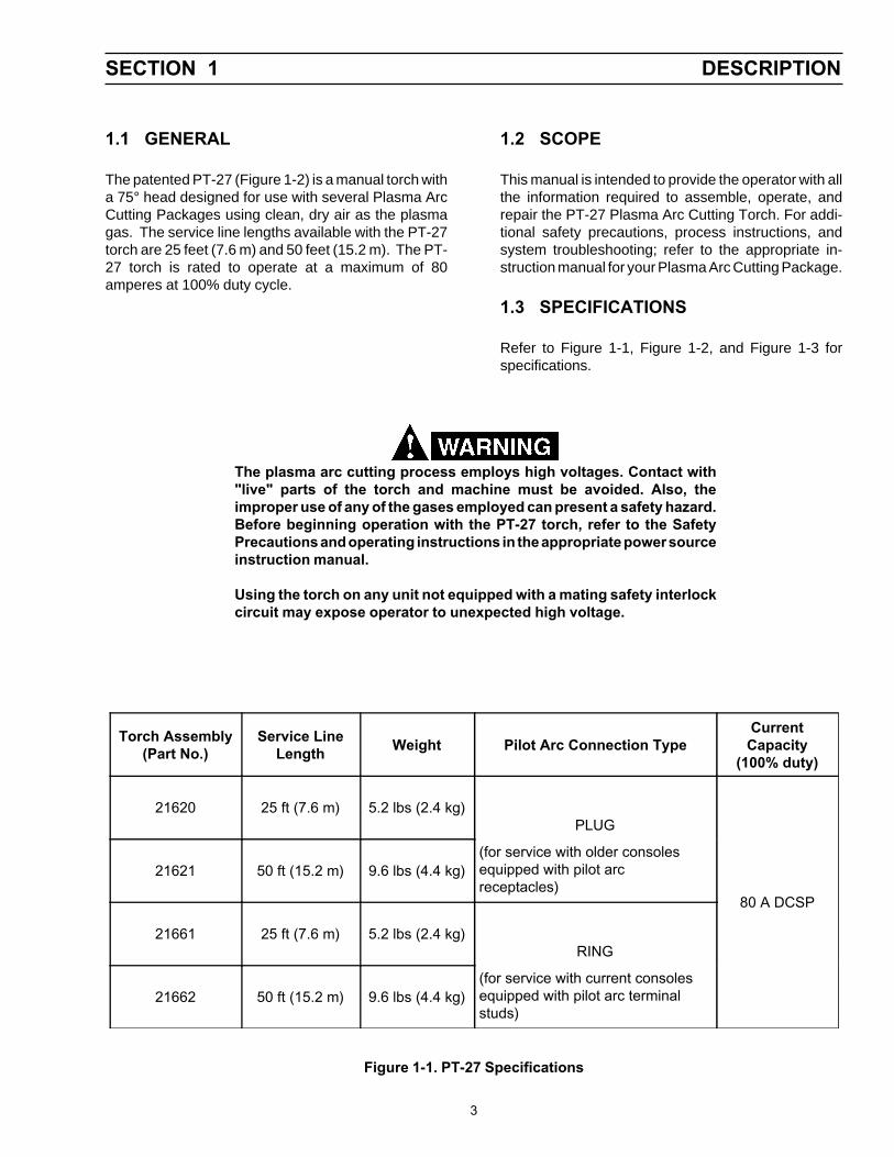
The patented PT-27 (Figure 1-2) is a manual torch witha 75° head designed for use with several Plasma ArcCutting Packages using clean, dry air as the plasmagas. The service line lengths available with the PT-27torch are 25 feet (7.6 m) and 50 feet (15.2 m). The PT-27 torch is rated to operate at a maximum of 80amperes at 100% duty cycle.
1.2 SCOPE
This manual is intended to provide the operator with allthe information required to assemble, operate, andrepair the PT-27 Plasma Arc Cutting Torch. For addi-tional safety precautions, process instructions, andsystem troubleshooting; refer to the appropriate in-struction manual for your Plasma Arc Cutting Package.
1.3 SPECIFICATIONS
Refer to Figure 1-1, Figure 1-2, and Figure 1-3 forspecifications.
The plasma arc cutting process employs high voltages. Contact with"live" parts of the torch and machine must be avoided. Also, theimproper use of any of the gases employed can present a safety hazard.Before beginning operation with the PT-27 torch, refer to the SafetyPrecautions and operating instructions in the appropriate power sourceinstruction manual.
Using the torch on any unit not equipped with a mating safety interlockcircuit may expose operator to unexpected high voltage.
Torch Assembly(Part No.)
Service LineLength Weight Pilot Arc Connection Type
CurrentCapacity
(100% duty)
21620 25 ft (7.6 m) 5.2 lbs (2.4 kg)PLUG
80 A DCSP
21621 50 ft (15.2 m) 9.6 lbs (4.4 kg)(for service with older consolesequipped with pilot arcreceptacles)
21661 25 ft (7.6 m) 5.2 lbs (2.4 kg)RING
21662 50 ft (15.2 m) 9.6 lbs (4.4 kg)(for service with current consolesequipped with pilot arc terminalstuds)
Figure 1-1. PT-27 Specifications
SECTION 1 DESCRIPTION
4
SECTION 1 DESCRIPTION
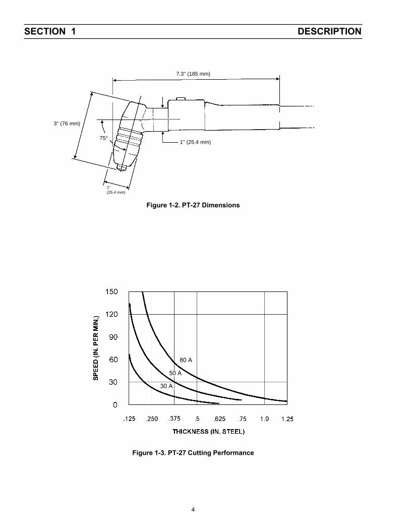
Figure 1-2. PT-27 Dimensions
7.3" (185 mm)
1" (25.4 mm)
1"(25.4 mm)
75°
3" (76 mm)
Figure 1-3. PT-27 Cutting Performance
50 A
80 A
30 A
5
SECTION 1 DESCRIPTION
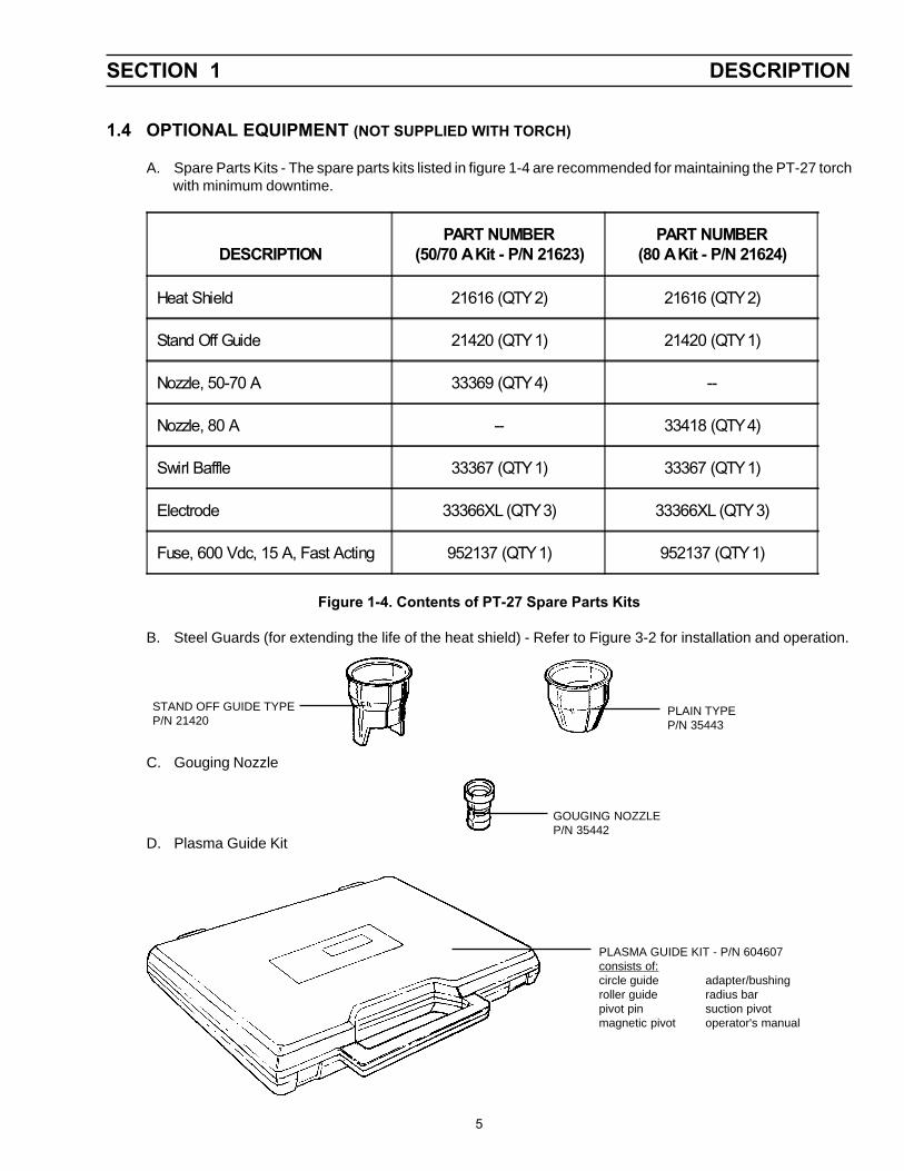
PLASMA GUIDE KIT - P/N 604607consists of:circle guide adapter/bushingroller guide radius barpivot pin suction pivotmagnetic pivot operator's manual
PLAIN TYPEP/N 35443
GOUGING NOZZLEP/N 35442
STAND OFF GUIDE TYPEP/N 21420
1.4 OPTIONAL EQUIPMENT (NOT SUPPLIED WITH TORCH)
A. Spare Parts Kits - The spare parts kits listed in figure 1-4 are recommended for maintaining the PT-27 torchwith minimum downtime.
Figure 1-4. Contents of PT-27 Spare Parts Kits
B. Steel Guards (for extending the life of the heat shield) - Refer to Figure 3-2 for installation and operation.
C. Gouging Nozzle
D. Plasma Guide Kit
DESCRIPTIONPART NUMBER
(50/70 A Kit - P/N 21623)PART NUMBER
(80 A Kit - P/N 21624)
Heat Shield 21616 (QTY 2) 21616 (QTY 2)
Stand Off Guide 21420 (QTY 1) 21420 (QTY 1)
Nozzle, 50-70 A 33369 (QTY 4) --
Nozzle, 80 A -- 33418 (QTY 4)
Swirl Baffle 33367 (QTY 1) 33367 (QTY 1)
Electrode 33366XL (QTY 3) 33366XL (QTY 3)
Fuse, 600 Vdc, 15 A, Fast Acting 952137 (QTY 1) 952137 (QTY 1)
6
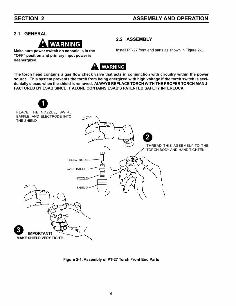
2.1 GENERAL
Make sure power switch on console is in the"OFF" position and primary input power isdeenergized.
2.2 ASSEMBLY
Install PT-27 front end parts as shown in Figure 2-1.
The torch head contains a gas flow check valve that acts in conjunction with circuitry within the powersource. This system prevents the torch from being energized with high voltage if the torch switch is acci-dentally closed when the shield is removed. ALWAYS REPLACE TORCH WITH THE PROPER TORCH MANU-FACTURED BY ESAB SINCE IT ALONE CONTAINS ESAB'S PATENTED SAFETY INTERLOCK.
! WARNING
ELECTRODE
SWIRL BAFFLE
NOZZLE
SHIELD
THREAD THIS ASSEMBLY TO THETORCH BODY AND HAND TIGHTEN.
2
3 IMPORTANT!MAKE SHIELD VERY TIGHT!
PLACE THE NOZZLE, SWIRLBAFFLE, AND ELECTRODE INTOTHE SHIELD
1
Figure 2-1. Assembly of PT-27 Torch Front End Parts
SECTION 2 ASSEMBLY AND OPERATION
7
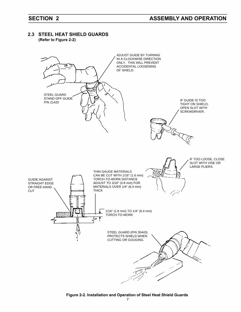
2.3 STEEL HEAT SHIELD GUARDS(Refer to Figure 2-2)
THIN GAUGE MATERIALSCAN BE CUT WITH 1/16" (1.6 mm)TORCH-TO-WORK DISTANCEADJUST TO 3/16" (4.8 mm) FORMATERIALS OVER 1/4" (6.4 mm)THICK
ADJUST GUIDE BY TURNINGIN A CLOCKWISE DIRECTIONONLY. THIS WILL PREVENTACCIDENTAL LOOSENINGOF SHIELD.
STEEL GUARDSTAND OFF GUIDEP/N 21420
IF GUIDE IS TOOTIGHT ON SHIELD,OPEN SLOT WITHSCREWDRIVER.
IF TOO LOOSE, CLOSESLOT WITH VISE ORLARGE PLIERS.
1/16" (1.6 mm) TO 1/4" (6.4 mm)TORCH-TO-WORK
GUIDE AGAINSTSTRAIGHT EDGEOR FREE-HANDCUT
STEEL GUARD (P/N 35443)PROTECTS SHIELD WHENCUTTING OR GOUGING.
Figure 2-2. Installation and Operation of Steel Heat Shield Guards
SECTION 2 ASSEMBLY AND OPERATION
8
3.1 GENERAL
Before any maintenance is attempted on thistorch, make sure the power switch on the consoleis in the "OFF" position and the primary input isdeenergized.
3.2 INSPECTION AND CLEANING OFCONSUMABLES
A. Disassemble the front end of the PT-27 asfollows:
1. Position torch head in a downward direction(refer to Figure 2-1) and remove the shield.The nozzle, swirl baffle, and electrode willdrop from the head and remain in the shield.Remove these components and inspect forwear. The nozzle and electrode will generallywear at the same rate. For best performance,
replace together.
2. Nozzle: Replace if the orifice is clogged, nicked,or out-of-round.
3. Electrode: See Figure 3-1 for electrode main-tenance.
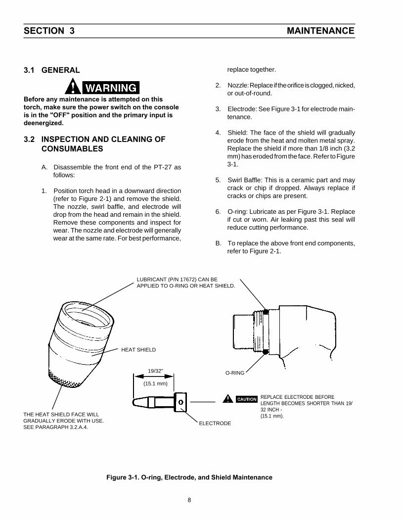
4. Shield: The face of the shield will graduallyerode from the heat and molten metal spray.Replace the shield if more than 1/8 inch (3.2mm) has eroded from the face. Refer to Figure3-1.
5. Swirl Baffle: This is a ceramic part and maycrack or chip if dropped. Always replace ifcracks or chips are present.
6. O-ring: Lubricate as per Figure 3-1. Replaceif cut or worn. Air leaking past this seal willreduce cutting performance.
B. To replace the above front end components,refer to Figure 2-1.
HEAT SHIELD
Figure 3-1. O-ring, Electrode, and Shield Maintenance
LUBRICANT (P/N 17672) CAN BEAPPLIED TO O-RING OR HEAT SHIELD.
THE HEAT SHIELD FACE WILLGRADUALLY ERODE WITH USE.SEE PARAGRAPH 3.2.A.4.
19/32"
(15.1 mm)
REPLACE ELECTRODE BEFORELENGTH BECOMES SHORTER THAN 19/32 INCH -(15.1 mm).
O-RING
ELECTRODE
SECTION 3 MAINTENANCE
9
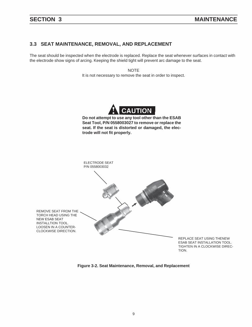
3.3 SEAT MAINTENANCE, REMOVAL, AND REPLACEMENT
The seat should be inspected when the electrode is replaced. Replace the seat whenever surfaces in contact withthe electrode show signs of arcing. Keeping the shield tight will prevent arc damage to the seat.
NOTEIt is not necessary to remove the seat in order to inspect.
Do not attempt to use any tool other than the ESABSeat Tool, P/N 0558003027 to remove or replace theseat. If the seat is distorted or damaged, the elec-trode will not fit properly.
REMOVE SEAT FROM THETORCH HEAD USING THENEW ESAB SEATINSTALLTION TOOL.LOOSEN IN A COUNTER-CLOCKWISE DIRECTION.
Figure 3-2. Seat Maintenance, Removal, and Replacement
ELECTRODE SEATP/N 0558003032
SECTION 3 MAINTENANCE
REPLACE SEAT USING THENEWESAB SEAT INSTALLATION TOOL.TIGHTEN IN A CLOCKWISE DIREC-TION.
10
SECTION 3 MAINTENANCE
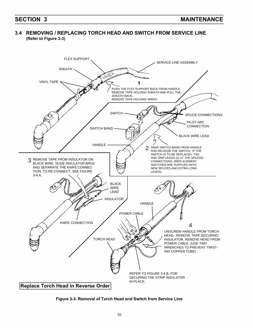
3.4 REMOVING / REPLACING TORCH HEAD AND SWITCH FROM SERVICE LINE(Refer to Figure 3-3)
1VINYL TAPE
FLEX SUPPORT
SHEATH
SERVICE LINE ASSEMBLY
PUSH THE FLEX SUPPORT BACK FROM HANDLE.REMOVE TAPE HOLDING SHEATH AND PULL THESHEATH BACK.REMOVE TAPE HOLDING WIRES.
SWITCH
SWITCH BAND
HANDLE
SPLICE CONNECTIONS
PILOT ARCCONNECTION
BLACK WIRE LEAD
SNAP SWITCH BAND FROM HANDLEAND RELEASE THE SWITCH. IF THESWITCH IS TO BE REPLACED, TAGAND SNIP LEADS (2) AT THE SPLICEDCONNECTIONS. (REPLACEMENTSWITCHES ARE SUPPLIED WITHNEW SPLICES AND EXTRA LONGLEADS)
2
1
REMOVE TAPE FROM INSULATOR ONBLACK WIRE. SLIDE INSULATOR BACKAND SEPARATE THE KNIFE CONNEC-TION. TO RE-CONNECT, SEE FIGURE3-4 A.
3
BLACKWIRELEAD
INSULATOR
KNIFE CONNECTION
UNSCREW HANDLE FROM TORCHHEAD. REMOVE TAPE SECURINGINSULATOR. REMOVE HEAD FROMPOWER CABLE. (USE TWOWRENCHES TO PREVENT TWIST-ING COPPER TUBE)
HANDLE
POWER CABLE
TORCH HEAD
REFER TO FIGURE 3-4 B, FORSECURING THE STRIP INSULATORIN PLACE.
4
Figure 3-3. Removal of Torch Head and Switch from Service Line
Replace Torch Head in Reverse Order
11
SECTION 3 MAINTENANCE
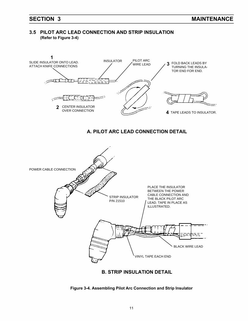
3.5 PILOT ARC LEAD CONNECTION AND STRIP INSULATION(Refer to Figure 3-4)
SLIDE INSULATOR ONTO LEAD.ATTACH KNIFE CONNECTIONS
INSULATOR
CENTER INSULATOROVER CONNECTION TAPE LEADS TO INSULATOR.
1
2
3 FOLD BACK LEADS BYTURNING THE INSULA-TOR END FOR END.
4
A. PILOT ARC LEAD CONNECTION DETAIL
POWER CABLE CONNECTION
STRIP INSULATORP/N 21510
PLACE THE INSULATORBETWEEN THE POWERCABLE CONNECTION ANDTHE BLACK PILOT ARCLEAD. TAPE IN PLACE ASILLUSTRATED.
VINYL TAPE EACH END
BLACK WIRE LEAD
B. STRIP INSULATION DETAIL
Figure 3-4. Assembling Pilot Arc Connection and Strip Insulator
PILOT ARCWIRE LEAD
12
SECTION 3 MAINTENANCE
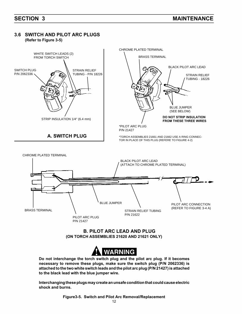
3.6 SWITCH AND PILOT ARC PLUGS(Refer to Figure 3-5)
Figure3-5. Switch and Pilot Arc Removal/Replacement
STRAIN RELIEFTUBING - 18226
SWITCH PLUGP/N 2062336
WHITE SWITCH LEADS (2)FROM TORCH SWITCH
STRAIN RELIEFTUBING - P/N 18226
STRIP INSULATION 1/4" (6.4 mm)
BRASS TERMINAL
BLACK PILOT ARC LEAD
BLUE JUMPER(SEE BELOW)
DO NOT STRIP INSULATIONFROM THESE THREE WIRES
*PILOT ARC PLUGP/N 21427
BLACK PILOT ARC LEAD(ATTACH TO CHROME PLATED TERMINAL)
PILOT ARC CONNECTION(REFER TO FIGURE 3-4 A)
BLUE JUMPER
STRAIN RELIEF TUBINGP/N 21622
PILOT ARC PLUGP/N 21427
BRASS TERMINAL
CHROME PLATED TERMINAL
A. SWITCH PLUG
CHROME PLATED TERMINAL
B. PILOT ARC LEAD AND PLUG(ON TORCH ASSEMBLIES 21620 AND 21621 ONLY)
Do not interchange the torch switch plug and the pilot arc plug. If it becomesnecessary to remove these plugs, make sure the switch plug (P/N 2062336) isattached to the two white switch leads and the pilot arc plug (P/N 21427) is attachedto the black lead with the blue jumper wire.
Interchanging these plugs may create an unsafe condition that could cause electricshock and burns.
*TORCH ASSEMBLIES 21661 AND 21662 USE A RING CONNEC-TOR IN PLACE OF THIS PLUG (REFERE TO FIGURE 4-2)

13
Replacement parts may be ordered from your ESABdistributor or from:
ESAB Welding & Cutting ProductsAttn.: Customer Service Dept.PO Box 100545, Ebenezer RoadFlorence, SC, 29501-0545
Refer to the Communication Guide located on the lastpage of this manual for a list of customer service phonenumbers.
4.1 General
Replacement parts are illustrated on the following fig-ures. When ordering replacement parts, order by partnumber and part name, as listed. Always provide theseries or serial number of the unit on which the parts willbe used. The serial number is stamped on the unitnameplate.
SECTION 4 REPLACEMENT PARTS
14
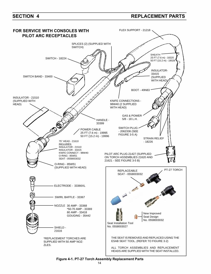
SECTION 4 REPLACEMENT PARTS
FLEX SUPPORT - 21218
SPLICES (2) (SUPPLIED WITHSWITCH)
SWITCH - 18224
SWITCH BAND - 33400
INSULATOR - 21510(SUPPLIED WITHHEAD)
SHIELD -21616
NOZZLE 30 AMP - 33368*50-70 AMP - 3336980 AMP - 33418GOUGING - 35442
SWIRL BAFFLE - 33367
ELECTRODE - 33366XL
O-RING - 85W51(SUPPLIED WITH HEAD)
SHEATH25 FT (7.6 m) - 1832050 FT (15.2 m) - 19026
INSULATOR-33415(SUPPLIEDWITH HEAD)
KNIFE CONNECTIONS -98W40 (2 SUPPLIEDWITH HEAD)
BOOT - 49N83
GAS & POWER5/8 - 18 L.H.HANDLE -
33399
PT-27 TORCH
PILOT ARC PLUG-21427 (SUPPLIEDON TORCH ASSEMBLIES 21620 AND21621 - SEE FIGURE 3-5 B)
STRAIN RELIEF- 18226
POWER CABLE25 FT (7.6 m) - 1999550 FT (15.2 m) - 19996
SWITCH PLUG- 2062336 (SEEFIGURE 3-5 A)
75° HEAD - 21610INCLUDES:INSULATOR - 21510INSULATOR - 33415KNIFE CONNECT - 98W40O-RING - 85W51SEAT - 0558003032
FOR SERVICE WITH CONSOLES WITHPILOT ARC RECEPTACLES
Figure 4-1. PT-27 Torch Assembly Replacement Parts
*REPLACEMENT TORCHES ARESUPPLIED WITH 50 AMP NOZ-ZLES.
REPLACEABLESEAT - 0558003032
THE SEAT IS REMOVED AND REPLACED USING THEESAB SEAT TOOL. (REFER TO FIGURE 3-2)
ALL TORCH ASSEMBLIES AND REPLACEMENTHEADS ARE SUPPLIED WITH THE SEAT INSTALLED.
New ImprovedSeat DesignNo. 0558003032
Seat Installation ToolNo. 0558003027
15
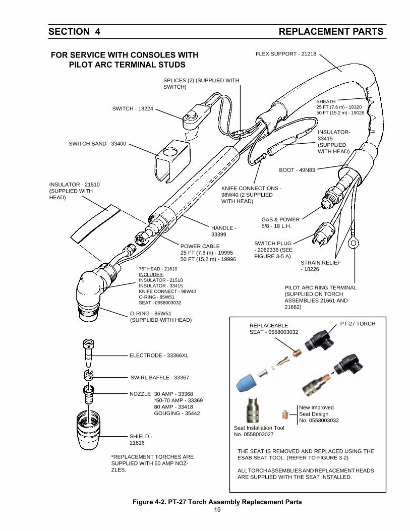
SECTION 4 REPLACEMENT PARTS
FLEX SUPPORT - 21218
SPLICES (2) (SUPPLIED WITHSWITCH)
SWITCH - 18224
SWITCH BAND - 33400
INSULATOR - 21510(SUPPLIED WITHHEAD)
SHIELD -21616
NOZZLE 30 AMP - 33368*50-70 AMP - 3336980 AMP - 33418GOUGING - 35442
SWIRL BAFFLE - 33367
ELECTRODE - 33366XL
O-RING - 85W51(SUPPLIED WITH HEAD)
SHEATH25 FT (7.6 m) - 1832050 FT (15.2 m) - 19026
INSULATOR-33415(SUPPLIEDWITH HEAD)
KNIFE CONNECTIONS -98W40 (2 SUPPLIEDWITH HEAD)
BOOT - 49N83
GAS & POWER5/8 - 18 L.H.HANDLE -
33399
POWER CABLE25 FT (7.6 m) - 1999550 FT (15.2 m) - 19996
SWITCH PLUG- 2062336 (SEEFIGURE 3-5 A)
PILOT ARC RING TERMINAL(SUPPLIED ON TORCHASSEMBLIES 21661 AND21662)
STRAIN RELIEF- 1822675° HEAD - 21610
INCLUDES:INSULATOR - 21510INSULATOR - 33415KNIFE CONNECT - 98W40O-RING - 85W51SEAT - 0558003032
FOR SERVICE WITH CONSOLES WITHPILOT ARC TERMINAL STUDS
Figure 4-2. PT-27 Torch Assembly Replacement Parts
*REPLACEMENT TORCHES ARESUPPLIED WITH 50 AMP NOZ-ZLES.
PT-27 TORCHREPLACEABLESEAT - 0558003032
THE SEAT IS REMOVED AND REPLACED USING THEESAB SEAT TOOL. (REFER TO FIGURE 3-2)
ALL TORCH ASSEMBLIES AND REPLACEMENT HEADSARE SUPPLIED WITH THE SEAT INSTALLED.
New ImprovedSeat DesignNo. 0558003032
Seat Installation ToolNo. 0558003027
F-15-203-C 1/02 Printed in U.S.A.
IF YOU DO NOT KNOW WHOM TO CALL
Telephone: (800) ESAB-123/ Fax: (843) 664-4452/ Web:http://www.esab.com
Hours: 7:30 AM to 5:00 PM EST
A. CUSTOMER SERVICE QUESTIONS:Order Entry Product Availability Pricing DeliveryOrder Changes Saleable Goods Returns Shipping Information
Eastern Distribution Center Telephone: (800)362-7080 / Fax: (800) 634-7548
Central Distribution Center Telephone: (800)783-5360 / Fax: (800) 783-5362
Western Distribution Center Telephone: (800) 235-4012/ Fax: (888) 586-4670
B. ENGINEERING SERVICE: Telephone: (843) 664-4416 / Fax : (800) 446-5693Welding Equipment Troubleshooting Hours: 7:30 AM to 5:00 PM ESTWarranty Returns Authorized Repair Stations
C. TECHNICAL SERVICE: Telephone: (800) ESAB-123/ Fax: (843) 664-4452Part Numbers Technical Applications Hours: 8:00 AM to 5:00 PM ESTPerformance Features Technical Specifications Equipment Recommendations
D. LITERATURE REQUESTS: Telephone: (843) 664-5562 / Fax: (843) 664-5548Hours: 7:30 AM to 4:00 PM EST
E. WELDING EQUIPMENT REPAIRS: Telephone: (843) 664-4487 / Fax: (843) 664-5557Repair Estimates Repair Status Hours: 7:30 AM to 3:30 PM EST
F. WELDING EQUIPMENT TRAINING:Telephone: (843)664-4428 / Fax: (843) 679-5864Training School Information and Registrations Hours: 7:30 AM to 4:00 PM EST
G. WELDING PROCESS ASSISTANCE:Telephone: (800) ESAB-123 Hours: 7:30 AM to 4:00 PM EST
H. TECHNICAL ASST. CONSUMABLES:Telephone : (800) 933-7070 Hours: 7:30 AM to 5:00 PM EST
ESAB Welding & Cutting Products, Florence, SC Welding EquipmentCOMMUNICATION GUIDE - CUSTOMER SERVICES