PSR1212 - ClearOne€¦ · PSR1212 White Paper ... • Preset and macro passwords.Presets and...
66
PSR1212 White Paper
Transcript of PSR1212 - ClearOne€¦ · PSR1212 White Paper ... • Preset and macro passwords.Presets and...

PSR1212
White Paper

Technical Services Group ~ 1-800-283-5936 (USA) ~ 1-801-974-3760
ii
PSR1212 White Paper
ClearOne Part No. 800-155-002
June 2002 (Rev. 2.0)
© 2002 ClearOne Communications, Inc. All
rights reserved. No part of this document may
be reproduced in any form or by any means
without written permission from ClearOne
Communications, Inc. Printed in the United
States of America. ClearOne Communications
reserves specific privileges. Information in this
document is subject to change without notice.

PSR1212 White Paper
Table of Contents
CHAPTER 1: Introduction . . . . . . . . . . . . . . . . . . . . . . . .1
Overview . . . . . . . . . . . . . . . . . . . . . . . . . . . . . . . . . . . . . . . . . . . . . . .1
Controls and Connections . . . . . . . . . . . . . . . . . . . . . . . . . . . . . . . . . . . . .3
Expansion Bus Connections . . . . . . . . . . . . . . . . . . . . . . . . . . . . . . . . . . .4
CHAPTER 2: Inputs and Outputs . . . . . . . . . . . . . . . . . . . .7
Mic Input Audio Path . . . . . . . . . . . . . . . . . . . . . . . . . . . . . . . . . . . . . . .7
Line Inputs . . . . . . . . . . . . . . . . . . . . . . . . . . . . . . . . . . . . . . . . . . . . . . .8
Line Outputs . . . . . . . . . . . . . . . . . . . . . . . . . . . . . . . . . . . . . . . . . . . . . .9
CHAPTER 3: Automatic Mic Mixing . . . . . . . . . . . . . . . . .11
Intelligible, Reliable Audio . . . . . . . . . . . . . . . . . . . . . . . . . . . . . . . . . . . .11
Automixing with the PSR1212 . . . . . . . . . . . . . . . . . . . . . . . . . . . . . . . . .12
CHAPTER 4: Audio Routing . . . . . . . . . . . . . . . . . . . . . . .19
Matrix Mixing . . . . . . . . . . . . . . . . . . . . . . . . . . . . . . . . . . . . . . . . . . . .19
Worksheets . . . . . . . . . . . . . . . . . . . . . . . . . . . . . . . . . . . . . . . . . . . . . . .21
CHAPTER 5: System Control . . . . . . . . . . . . . . . . . . . . . .23
Presets and Macros . . . . . . . . . . . . . . . . . . . . . . . . . . . . . . . . . . . . . . . . .23
Control and Status Connectors . . . . . . . . . . . . . . . . . . . . . . . . . . . . . . . . .24
ClearOne Control Devices . . . . . . . . . . . . . . . . . . . . . . . . . . . . . . . . . . . . .27
Serial Control (RS-232) . . . . . . . . . . . . . . . . . . . . . . . . . . . . . . . . . . . . . .28
Front Panel . . . . . . . . . . . . . . . . . . . . . . . . . . . . . . . . . . . . . . . . . . . . . . .29
Technical Services Group ~ 1-800-283-5936 (USA) ~ 1-801-974-3760
iii

Technical Services Group: 1-800-283-5936 (USA) ~ 1-801-974-3760
iv
CHAPTER 6: PSR1212 Connections . . . . . . . . . . . . . . . . . .31
System Connections . . . . . . . . . . . . . . . . . . . . . . . . . . . . . . . . . . . . . . . . .31
Expansion Bus Connections . . . . . . . . . . . . . . . . . . . . . . . . . . . . . . . . . . .32
CHAPTER 7: Applications . . . . . . . . . . . . . . . . . . . . . . . . .35
Auditorium Installation . . . . . . . . . . . . . . . . . . . . . . . . . . . . . . . . . . . . . .35
Arena Installation . . . . . . . . . . . . . . . . . . . . . . . . . . . . . . . . . . . . . . . . . .37
Movie Theater Installation . . . . . . . . . . . . . . . . . . . . . . . . . . . . . . . . . . . .38
Gymnasium Installation . . . . . . . . . . . . . . . . . . . . . . . . . . . . . . . . . . . . . .40
Hotel/Convention Center Installation . . . . . . . . . . . . . . . . . . . . . . . . . . . . .41
Conference Room Installation . . . . . . . . . . . . . . . . . . . . . . . . . . . . . . . . . .43
Training Room Installation . . . . . . . . . . . . . . . . . . . . . . . . . . . . . . . . . . . .44
Boardroom Installation . . . . . . . . . . . . . . . . . . . . . . . . . . . . . . . . . . . . . .46
Corporate Paging System . . . . . . . . . . . . . . . . . . . . . . . . . . . . . . . . . . . .47
Appendices . . . . . . . . . . . . . . . . . . . . . . . . . . . . . . . . . . . .49
Appendix A: Specifications . . . . . . . . . . . . . . . . . . . . . . . . . . . . . . . . . . . .49
Appendix B: Architectural and Engineering Specifications . . . . . . . . . . . . .50
Appendix C: Worksheets . . . . . . . . . . . . . . . . . . . . . . . . . . . . . . . . . . . . . .51
Appendix D: Glossary . . . . . . . . . . . . . . . . . . . . . . . . . . . . . . . . . . . . . . .57

Technical Services Group: 1-800-283-5936 (USA) ~ 1-801-974-3760
Introduction ~ Overview
CHAPTER 1: Introduction
Overview
Audio is critical to human communication. Media such as voice mail, the Internet, conference calling, video conferencing,
and electronic presentations are driving the demand for better audio-communication technologies. The sound reinforcement
arena also demands higher-quality sound to more faithfully reproduce source audio. At the same time, organizations using
audio-communication technologies are looking for ways to decrease costs and complexity while increasing efficiency.
The PSR1212 Digital Matrix Mixer with Audio Processing meets the demands of a wide variety of sound
reinforcement and conferencing requirements with 12x12 digital matrix mixing, parametric equalizers, filters, and 32
customizable presets. These features enable the PSR1212 to create a quality audio experience in many venues—from
auditoriums and arenas to training rooms and boardrooms.
A quality audio experience is one where the audio source material is the message, not the audible inadequacies of a
poorly designed or configured audio system. With a properly configured PSR1212, participants and observers do not
become fatigued by reverberated audio, which reduces sound clarity.
For ease of use, the PSR1212 facilitates local and remote PC setup and diagnostics, logic outputs, and gated
microphone operation. Microphone inputs can be individually customized to gate on and off as you want, while
automatic gain control keeps the overall sound level consistent. Input channels 1–8 can be configured as an automatic
microphone mixer.
Audio routing is simplified with G-Ware’s Matrix Screen. Any combination of inputs can be routed to any
combination of outputs, allowing flexibility in accommodating different applications and customer requirements.
Adjustments in routing, level, and other functions can be made through presets activated through a closure on the
rear panel or an RS-232 serial interface.
Features and benefits• 12x12 matrix mixer with level control at the cross points.
• Twelve line output channels. All output levels are adjustable and can be muted.
• Eight audio processing buses, each with 15 filters, can be placed anywhere within the matrix mixer audio path.
• Eight-channel automatic microphone mixer with four line inputs. The mixer operates across linked units.
• Gain, audio processing, muting, and automatic mic mixing can be configured for each mic input channel.
• Configurable audio processor with four filters on inputs 1–8.
• All interconnected devices can be accessed, controlled, and programmed via a single RS-232 connection.
Technical Services Group: 1-800-283-5936 (USA) ~ 1-801-974-3760
2 Introduction ~ Overview
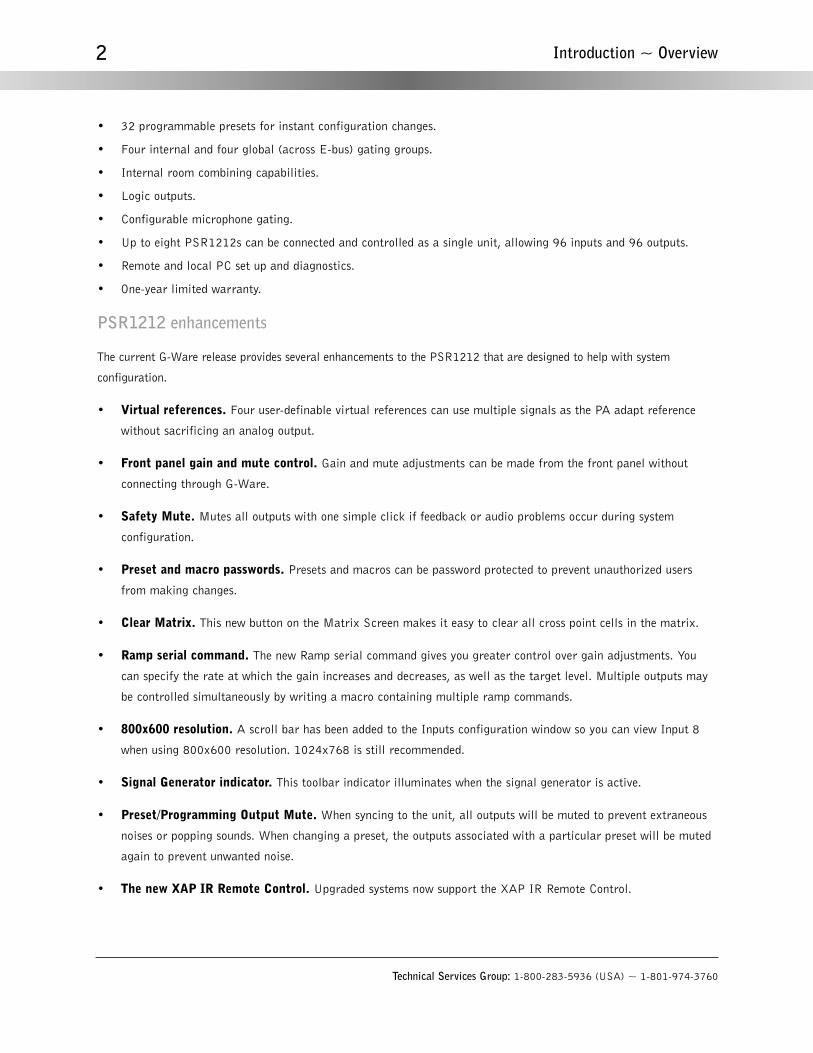
• 32 programmable presets for instant configuration changes.
• Four internal and four global (across E-bus) gating groups.
• Internal room combining capabilities.
• Logic outputs.
• Configurable microphone gating.
• Up to eight PSR1212s can be connected and controlled as a single unit, allowing 96 inputs and 96 outputs.
• Remote and local PC set up and diagnostics.
• One-year limited warranty.
PSR1212 enhancements
The current G-Ware release provides several enhancements to the PSR1212 that are designed to help with system
configuration.
• Virtual references. Four user-definable virtual references can use multiple signals as the PA adapt reference
without sacrificing an analog output.
• Front panel gain and mute control. Gain and mute adjustments can be made from the front panel without
connecting through G-Ware.
• Safety Mute. Mutes all outputs with one simple click if feedback or audio problems occur during system
configuration.
• Preset and macro passwords. Presets and macros can be password protected to prevent unauthorized users
from making changes.
• Clear Matrix. This new button on the Matrix Screen makes it easy to clear all cross point cells in the matrix.
• Ramp serial command. The new Ramp serial command gives you greater control over gain adjustments. You
can specify the rate at which the gain increases and decreases, as well as the target level. Multiple outputs may
be controlled simultaneously by writing a macro containing multiple ramp commands.
• 800x600 resolution. A scroll bar has been added to the Inputs configuration window so you can view Input 8
when using 800x600 resolution. 1024x768 is still recommended.
• Signal Generator indicator. This toolbar indicator illuminates when the signal generator is active.
• Preset/Programming Output Mute. When syncing to the unit, all outputs will be muted to prevent extraneous
noises or popping sounds. When changing a preset, the outputs associated with a particular preset will be muted
again to prevent unwanted noise.
• The new XAP IR Remote Control. Upgraded systems now support the XAP IR Remote Control.

Technical Services Group: 1-800-283-5936 (USA) ~ 1-801-974-3760
3Introduction ~ Controls and Connections
Controls and Connections
Front panel
A. LCD. Used for numeric display of audio levels, gain readouts, and limited setup and programming functions.
B. Enter//ESC. Used to navigate the PSR1212’s menu system.
C. LED Meter. This LED bar meter is used to display the audio level of an input, output, or processing channel of
the PSR1212.
D. Meter. Takes you directly to the Meter branch of the PSR1212’s LCD menu tree.
E. Mic On LED. These LEDs indicate microphone gate status.
Rear panel
A. Power. The power module accommodates an AC voltage input of 100–240VAC, 50/60Hz, 30W. No switching is
required.
B. Inputs 1–8. For mic and/or line level inputs.
C. RS-485 Remote Control Ports. These four-pin Phoenix ports allow you to control the PSR1212 with a
ClearOne Control Panel or the XAP IR Remote Control.
D. Outputs 1–8, 9–12. Line level outputs that may be configured for any combination of gated and non-gated
inputs, as well as a mix of mic and line level inputs.
E. Inputs 9–12. For line level inputs.
F. Expansion Bus In/Out. Used for daisy-chaining PSR1212 units in a network.
Product description ~ Introduction
Figure 1.1. PSR1212 front panel
Expansion BusIn Out
Figure 1.2. PSR1212 rear panel connections

G. RS-232. This DB-9 serial port is to connect the PSR1212 to a PC, modem, or other custom remote controller.
H. Control/Status Ports A and B. These DB-25 connectors are for connecting control devices. The control devices
have access to the command set for the PSR1212 and can be used for functions such as volume, muting, preset
change, room combining, etc. Devices can be connected to either port.
Expansion Bus Connections
The expansion bus (E-bus) network architecture allows up to eight PSR1212s to be controlled as if part of a single unit
and makes it possible to route audio to and from any destination on the expansion bus network. It contains 12 independent
digital audio buses labeled O–Z and four PA Adapt reference buses. Each audio bus can route mic or line level inputs in
any combination across the expansion bus network. These buses are divided into two groups—O–R buses and S–Z buses—
based on their capabilities and default settings. The E-bus also contains four global gating buses and one control bus.
• O–R buses. These four audio buses are defaulted as the mic mix buses; they can communicate the NOM count
across the network to other PSR1212s. Otherwise, these buses are identical to buses S–Z.
• S–Z buses. These eight buses are defaulted as auxiliary mix buses. They are used to route auxiliary audio, such
as from a CD player or VCR, to and from other units on the network. These buses are also used as mic mix buses
when NOM count is not required.
• PA Adapt reference buses. These buses provide a system-wide bus for input channels to receive a reference
input for PA Adaptive Mode. See page 14 for more information about PA Adaptive mode.
• Global Gating Groups A–D. These mix-minus buses support first-mic priority, maximum number of mics, etc.,
and work across all linked PSR1212s. Unlike the audio buses, they contain only mic status and gate parameters.
All gated mics are default routed to the A mixer and to the O bus for routing.
• Control bus. The control bus is an independent channel from the E-bus’s audio channel; it uses a different pair
of wires on the same E-bus cable. This design allows control information to pass even if the units are not using
the audio link.
Network requirements
The maximum distance allowed between any two PSR1212 units on an expansion bus network is 80 feet (24 meters).
ClearOne recommends category five twisted-pair (10BaseT) cable be used to connect units.
Equipment placement
The PSR1212 is designed for a 19" equipment rack. With a desktop kit, it can be modified for tabletop placement. The
PSR1212 can safely operate in temperatures between 32°–110° F/0°–38° C. Do not block any of the ventilation holes.
Technical Services Group: 1-800-283-5936 (USA) ~ 1-801-974-3760
4 Introduction ~ Expansion Bus Connections

Technical Services Group: 1-800-283-5936 (USA) ~ 1-801-974-3760
5Introduction ~ Expansion Bus Connections
Figure 1.3. Typical PSR1212 installation(simplified for illustrative purposes)

Technical Services Group: 1-800-283-5936 (USA) ~ 1-801-974-3760
6 Introduction ~ Expansion Bus Connections
Fin
e I
np
ut
Ga
in
Ph
an
tom
P
ow
er
On
/Off
Mic
55,
25
Lin
e
Fin
e I
np
ut
Ga
inF
ine
In
pu
t G
ain
Fin
e I
np
ut
Ga
inF
ine
In
pu
t G
ain
Fin
e I
np
ut
Ga
inF
ine
In
pu
t G
ain
Fin
e I
np
ut
Ga
in
On
On
On
On
On
Off
Off
Off
Off
Off
Mu
te
Fin
e I
np
ut
Ga
in
Inp
ut
Pro
cess
ing
On
Off
Mu
te
Ou
tpu
t G
ain
Off
NO
M
On
Off
Mu
te
Fin
e I
np
ut
Ga
in
On
Off
Mu
te
Fin
e I
np
ut
Ga
in
On
Off
Mu
te
Fin
e I
np
ut
Ga
inE
xpansi
on B
us
In/O
ut
Input 1
Input 2
Input 3
Input 4
Input 5
Input 6
Input 7
Input 8
Input 9
Input 10
Input 11
Input 12
Outp
ut 1
Outp
ut 2
Outp
ut 3
Outp
ut 4
Outp
ut 5
Outp
ut 6
Outp
ut 7
Outp
ut 8
Outp
ut 9
Outp
ut 10
Outp
ut 11
Outp
ut 12
Z Mixing Bus
On
Off
Mu
te
Ou
tpu
t G
ain
Off
NO
M
On
Off
Mu
te
Ou
tpu
t G
ain
Off
NO
M
On
Off
Mu
te
Ou
tpu
t G
ain
Off
NO
M
On
Off
Mu
te
Ou
tpu
t G
ain
Off
NO
M
On
Off
Mu
te
Ou
tpu
t G
ain
Off
NO
M
On
Off
Mu
te
Ou
tpu
t G
ain Off
NO
M
On
Off
Mu
te
Ou
tpu
t G
ain Off
NO
M
On
Off
Mu
te
Ou
tpu
t G
ain Off
NO
M
On
Off
Mu
te
Ou
tpu
t G
ain Off
NO
M
On
Off
Mu
te
Ou
tpu
t G
ain Off
NO
M
On
Off
Mu
te
Ou
tpu
t G
ain Off
NO
M
Ph
an
tom
P
ow
er
On/O
ff
Ph
an
tom
P
ow
er
On/O
ff
Ph
an
tom
P
ow
er
On
/Off
Ph
an
tom
P
ow
er
On
/Off
Ph
an
tom
P
ow
er
On
/Off
Ph
an
tom
P
ow
er
On
/Off
Ph
an
tom
P
ow
er
On
/Off
Mic
55
, 2
5Lin
eM
ic 5
5,
25
Lin
eM
ic 5
5, 2
5L
ine
Mic
55
, 2
5L
ine
Mic
55
,25
Lin
eM
ic 5
5, 2
5L
ine
Mic
55
, 2
5L
ine
Ma
trix
Inp
ut
Pro
cess
ing
Inp
ut
Pro
cess
ing
Inp
ut
Pro
cess
ing
Inp
ut
Pro
cess
ing
Inp
ut
Pro
cess
ing
Inp
ut
Pro
cess
ing
Inp
ut
Pro
cess
ing
AssignableProcessing
AssignableProcessing
AssignableProcessing
AssignableProcessing
AssignableProcessing
AssignableProcessing
AssignableProcessing
AssignableProcessing
A A
B B
C C
D D
E E
F F
G G
H H
Pro
cess
ing
outp
uts
are
loop
ed b
ack
into
the
mat
rix.
MM
MM
MM
MM
MM
MM M
To M
atr
ixF
rom
Ma
trix
De
lay
Co
mp
ress
or
15
Filt
ers
Ass
ign
ab
le P
roce
ssin
g
All
Pa
ssL
ow
Pa
ssH
igh
Pa
ssL
ow
Sh
elv
ing
Hig
h S
he
lvin
g
50
0m
SG
ain
Ad
just
Mu
te
MP
EQ
CD
Ho
rnB
ess
el C
ross
ove
rB
utt
erw
ort
hL
inkw
itz-R
iley
Control Bus
Y Mixing BusX Mixing BusW Mixing BusV Mixing BusU Mixing BusT Mixing BusS Mixing BusR Mixing BusQ Mixing BusP Mixing BusO Mixing Bus
Control/StatusB
Control/StatusA
Con
trol
Lo
gic
Fro
nt P
anel
Con
trol
Exp
ansi
on B
usR
S-4
85
Con
trol
Net
wor
kR
S-4
85
AG
C
On
Off
Mu
teA
uto
mix
er
4 F
ilte
rs
No
n-G
ate
d A
ud
io
Ga
ted
Au
dio
To M
atr
ix
Inp
ut
Pro
cess
ing
On
Off
Sys
tem
-Wid
eA
uto
mix
ing
Pa
ram
ete
rs
Mic
rop
ho
ne
Act
iva
tion
Au
to g
ate
/Ma
nu
al g
ate
/On
/Off
Ch
airm
an
Ove
rrid
eO
n/O
ffA
da
ptiv
e A
mb
ien
t
M
All
Pa
ssL
ow
Pass
Hig
h P
ass
PE
Q
M
On
On
On
On
On
On
On
On
On
On
On
On
M=
Met
er R
efer
ence
Poi
nt
No
tch
No
tch
MP
re-g
ain
Me
ter
Po
st-g
ain
Me
ter
MP
re-g
ain
Me
ter
MP
re-g
ain
Me
ter
MP
re-g
ain
Me
ter
MP
re-g
ain
Me
ter
MP
re-g
ain
Me
ter
MP
re-g
ain
Me
ter
MP
re-g
ain
Me
ter
MP
re-g
ain
Me
ter
MP
re-g
ain
Me
ter
MP
re-g
ain
Me
ter
MP
re-g
ain
Me
ter
MP
ost
-ga
inM
ete
r
MP
ost
-ga
inM
ete
r
MP
ost
-ga
inM
ete
r
MP
ost
-ga
inM
ete
r
MP
ost
-ga
inM
ete
r
MP
ost
-ga
inM
ete
r
MP
ost
-ga
inM
ete
r
MP
ost
-ga
inM
ete
r
MP
ost
-ga
inM
ete
r
MP
ost
-ga
inM
ete
r
MP
ost
-ga
inM
ete
r
Po
st-p
roce
ssin
gM
ete
r
Po
st-g
ain
Me
ter
MP
ost
-ga
ting
Me
ter
Po
st-p
roce
ssin
gM
ete
r
Post
-gain
Me
ter
Po
st-g
ain
Me
ter
Po
st-g
ain
Mete
rP
ost
-ga
inM
ete
rP
ost
-ga
inM
ete
rP
ost
-ga
inM
ete
rP
ost
-ga
inM
ete
rP
ost
-ga
inM
ete
rP
ost
-ga
inM
ete
rP
ost
-ga
inM
ete
rP
ost
-ga
inM
ete
rP
ost
-ga
inM
ete
r
RS
-232
AG
CA
GC
AG
CA
GC
Figu
re 1
.4.
PSR
1212
Blo
ck D
iagr
am
PSR1212 block diagram

CHAPTER 2: Inputs and OutputsThe PSR1212 has 12 inputs consisting of eight mic/line inputs and four line inputs. The unit has 12 line outputs. All
inputs and outputs are actively balanced. Inputs 1–8 have 4kΩ of terminating impedance while line level inputs 9–12
provide >20kΩ of termination. Outputs provide a source impedance of 50Ω. All levels are referenced to a 0dBu level.
Input and output level control is executed in the digital domain. As a result, input levels should never exceed
+20dBu. The unit will deliver a maximum output level of +20dBm. The PSR1212 utilizes 24-bit A/Ds and D/As while
sampling at a 48kHz rate. This results in a system-wide dynamic range of 100dB and a pass band from 20Hz to
20kHz. All input and output levels can be monitored in real time on the front-panel LCD and through the RS-232 serial
port. The LCD display and RS-232 port provide precise numeric readouts indicating level. This allows extremely precise
level calibration. Additionally, while monitoring numeric dBu audio levels, input and output gains can be adjusted for
optimum audio performance.
Mic Input Audio Path
Mic input settings are configured using G-Ware. Some settings (gain adjustments for example) can be
changed using front panel controls, serial commands, or parallel control through the Control/Status port.
The audio signal path for mic inputs is illustrated in the diagram on the following page.
Balanced audio is input through the rear panel Phoenix connections. Mic/line level selection occurs
first and phantom power is applied (if activated). The PSR1212 then converts the audio from analog
to digital for processing by the DSP engine. Once converted to digital, audio is level controlled and
passes through the channel mute function.
Audio next passes through filters. The PSR1212 has four configurable filters that can each be
set individually as an all-pass filter, a low-pass filter, a high-pass filter, or a parametric equalizer
(EQ). Each may be activated to equalize different types mics to sound similar, filter out unwanted
hum, etc. You can increase or decrease each band up to 15dB, in increments of .5dB on each input.
After the filters, automatic gain control (AGC) is applied. The purpose of the AGC is to
automatically increase gain when the level is too low and decrease gain when it is too high. AGC is
provided at all inputs and should be activated for mic or line inputs that experience audio level
fluctuation. For example, if audio coming from a video codec fluctuates depending on the connection
at the other end, the AGC will compensate for these differences.
At this point, non-gated audio is sent to the routing matrix for outputs that need non-gated
audio. The final stage (automixing) determines how the audio is directed through the post-gating
input to the routing matrix. A brief description of the automixing settings follows on the next page.
For more detailed information, see Automixing with the PSR1212 on page 12.
Technical Services Group: 1-800-283-5936 (USA) ~ 1-801-974-3760
Inputs and Outputs ~ Mic Input Audio Path
Figure 2.1. Mic inputconfiguration in G-Ware

Technical Services Group: 1-800-283-5936 (USA) ~ 1-801-974-3760
8
Automixing
Each input can be configured with a variety of automixing functions, including activation settings, chairman mic, and
adaptive ambient mode. The functions determine when, how, and why an individual microphone will gate on or off:
• Microphone Activation. There are two modes of mic activation that can be selected on a per-input basis: auto-
gate and manual gate on/off. In auto-gate mode, the input channel is voice activated, based on the selected
gating group parameters. In manual gate mode, the mic is activated by manually switching it on or off and
allowing the input to contribute to automixing parameters.
• Chairman Override (On or Off). Provides gating priority for chairman override enabled microphones within the
same gating group. When a mic with chairman override gates on, all mics that don’t have chairman override
enabled and are in the same gating group will gate off.
• Adaptive Ambient (On or Off). In the On mode, the ambient level used to calculate gating is based on the
room’s actual noise floor, integrated over time, as measured by the input in the room. In the Off mode, the
manual ambient level is set by the integrator, and will be used to calculate gating.
Line Inputs
The audio signal path for line inputs is shown above. The Gain, Mute, and AGC functions operate identically to the mic/line
inputs. Line input settings are configured in G-Ware.
Inputs and Outputs ~ Line Inputs
High PassFilter
On Off
AutomaticGain Control
On Off
AutomixerChannelMute
On Off
Non Gated Audio
Gated AudioTo Matrix
System Wide
Automatic Mixing
Parameters
Microphone Activation
Auto gate / Manuel gate / Override
Chairman Override
On / Off
Adaptive Ambient
On / Off
Phantom Power
On/OffInput
Gain
Mic/Line selection
55, 25, 0
Inputs 1–8
Figure 2.2. Inputs 1–8 signal path
On Off
Input
Gain
LineInputs9–12
On Off
Mute To MatrixAGC+
–
Figure 2.3. Line inputs signal path

Technical Services Group: 1-800-283-5936 (USA) ~ 1-801-974-3760
9
Line Outputs
Each of the 12 line outputs is identical. Three functions are associated with each output: number of open mics (NOM),
mute, and gain control.
Unlike most automixers that have a single master NOM output, the PSR1212 provides a NOM setting at every
output. Activation of NOM places this output only in a mode where, as more microphones routed to this output are
gated on (either by auto gate or manual gate), the total overall output gain will remain constant. This reduces the
possibility of feedback occuring and is most useful in sound reinforced applications.
Gain control allows you to set the output level. The mute function essentially turns the volume off. All of these
functions can be controlled via the RS-232 port or the control/status connector. For example, if you want to control the
volume of the speakers, you could use two control pins on the control/status connector for volume up and volume down.
Another pin could be used for mute.
Inputs and Outputs ~ Line Outputs
On Off
Output
Gain
LineOutputs1–12
On Off
NOMFrom Matrix
Mute+
–
D/A
Figure 2.4. Outputs 1–12 signal path

Technical Services Group: 1-800-283-5936 (USA) ~ 1-801-974-3760
10
CHAPTER 3: Automatic Mic Mixing
Intelligible, Reliable Audio
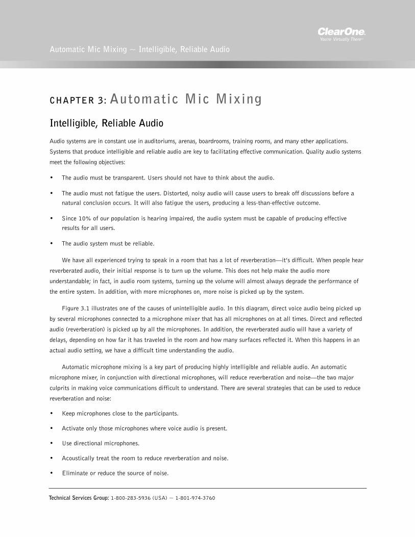
Audio systems are in constant use in auditoriums, arenas, boardrooms, training rooms, and many other applications.
Systems that produce intelligible and reliable audio are key to facilitating effective communication. Quality audio systems
meet the following objectives:
• The audio must be transparent. Users should not have to think about the audio.
• The audio must not fatigue the users. Distorted, noisy audio will cause users to break off discussions before a
natural conclusion occurs. It will also fatigue the users, producing a less-than-effective outcome.
• Since 10% of our population is hearing impaired, the audio system must be capable of producing effective
results for all users.
• The audio system must be reliable.
We have all experienced trying to speak in a room that has a lot of reverberation—it’s difficult. When people hear
reverberated audio, their initial response is to turn up the volume. This does not help make the audio more
understandable; in fact, in audio room systems, turning up the volume will almost always degrade the performance of
the entire system. In addition, with more microphones on, more noise is picked up by the system.
Figure 3.1 illustrates one of the causes of unintelligible audio. In this diagram, direct voice audio being picked up
by several microphones connected to a microphone mixer that has all microphones on at all times. Direct and reflected
audio (reverberation) is picked up by all the microphones. In addition, the reverberated audio will have a variety of
delays, depending on how far it has traveled in the room and how many surfaces reflected it. When this happens in an
actual audio setting, we have a difficult time understanding the audio.
Automatic microphone mixing is a key part of producing highly intelligible and reliable audio. An automatic
microphone mixer, in conjunction with directional microphones, will reduce reverberation and noise—the two major
culprits in making voice communications difficult to understand. There are several strategies that can be used to reduce
reverberation and noise:
• Keep microphones close to the participants.
• Activate only those microphones where voice audio is present.
• Use directional microphones.
• Acoustically treat the room to reduce reverberation and noise.
• Eliminate or reduce the source of noise.
Technical Services Group: 1-800-283-5936 (USA) ~ 1-801-974-3760
Automatic Mic Mixing ~ Intelligible, Reliable Audio

Automixing with the PSR1212
The PSR1212 was designed to implement automatic microphone mixing that increases audio intelligibility by reducing
overall multiple microphone pickup of reverberation and noise. Unlike most automixers, the PSR1212 implements its
mixing function completely in the digital domain. This greatly increases precision in making automixing decisions.
All audio is routed through the PSR1212 (both
microphone and loudspeaker audio), which means
the PSR1212 can more accurately make
microphone activation decisions.
For example, audio from another source (such
as music or audio from another room) is amplified
through the loudspeakers in the room. Typically, an
automixer would activate at least one microphone,
as if that audio were a voice in the room. This false
activation will not occur with the PSR1212 (see
Figure 3.2) because it raises the mic gate ratio
based on the audio level from the loudspeaker.
The PSR1212 has a variety of automixing
functions that are implemented on both a per-
channel basis and across the entire automatic mixer. These functions are described on page 13. Each PSR1212 can
have four separate automatic mixers working independently or as a single unit.
Technical Services Group: 1-800-283-5936 (USA) ~ 1-801-974-3760
12 Automatic Mic Mixing ~ Automixing with the PSR1212
Figure 3.1. Microphones pick up direct andreflected audio
Audio from
remote location
or other audio
Output to
remote location
This audio does not
activate a mic channel
on the PSR1212
Figure 3.2. Microphone activation

In addition, more microphone channels can be added by linking PSR1212 units via the expansion bus, the digital
network bus. Unlike other “expandable” automatic microphone mixers, the PSR1212 works as a single unit for up to
eight units networked together, for a total of 64 microphones. Expanded analog automixers can offer only limited
functionality such as NOM (number of open microphones). Multiple PSR1212 units can operate as a single unit
because all functions are implemented digitally and all units are connected together using the high-speed digital
network bus (expansion bus). See Figure 3.3.
Automixing parameters
Automixing or gating parameters are configured using
G-Ware and provide high precision, reliable microphone
mixing.
Activation
There are three mic activation settings: Auto Gate, Manual
On, and Manual Off.
• Auto Gate determines mic gating based on the input
level and gating settings for the gating group the input
is assigned to. It contributes to and is affected by all
gating group settings such as NOM, chairman override,
etc.
• Manual On activates a mic, provided it does not exceed
max NOM requirements of the gating group that the
input is assigned to. It is included in the NOM count.
• Manual Off deactivates a mic.
Technical Services Group: 1-800-283-5936 (USA) ~ 1-801-974-3760
13Automatic Mic Mixing ~ Automixing with the PSR1212
1 2 3 5 7 8 9 10 11 12 13 14 15 16 57 58 59 60 61 62 63 64
PSR1212
64
E-bus
PSR1212 (0) PSR1212 (1) PSR1212 (7)
Figure 3.3. Expansion Bus Control of 64 Mics
Figure 3.4. Gating parameters window in G-Ware
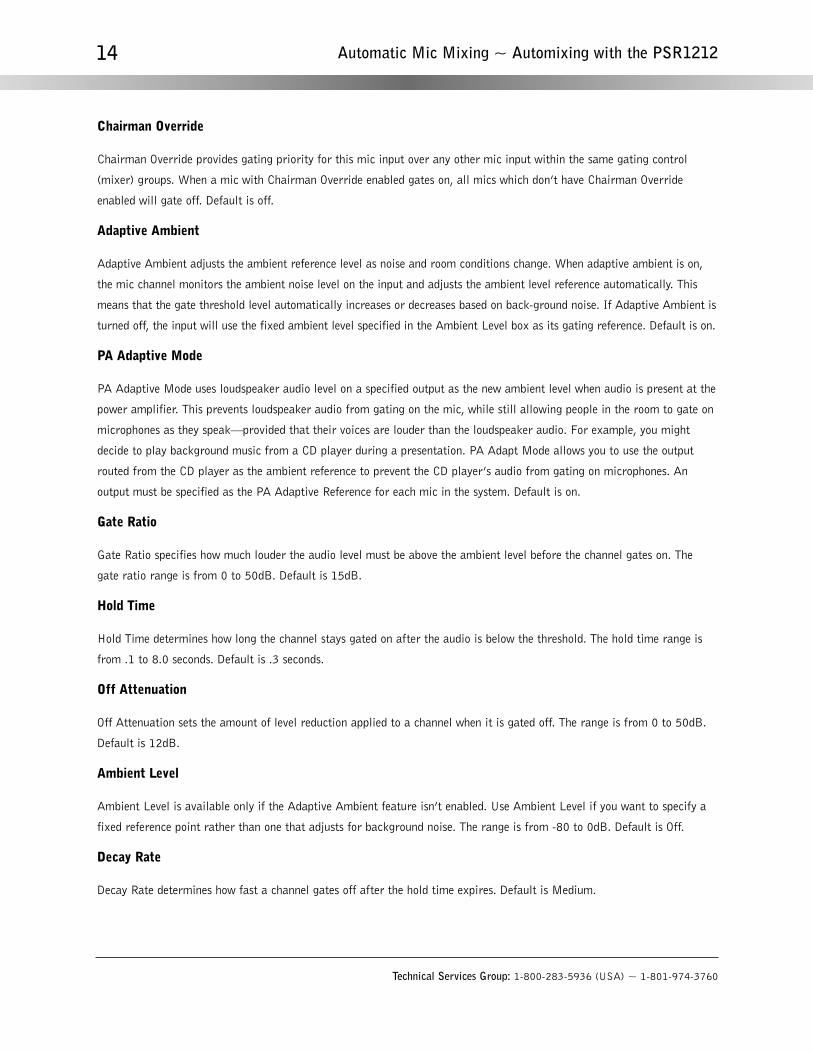
Chairman Override
Chairman Override provides gating priority for this mic input over any other mic input within the same gating control
(mixer) groups. When a mic with Chairman Override enabled gates on, all mics which don’t have Chairman Override
enabled will gate off. Default is off.
Adaptive Ambient
Adaptive Ambient adjusts the ambient reference level as noise and room conditions change. When adaptive ambient is on,
the mic channel monitors the ambient noise level on the input and adjusts the ambient level reference automatically. This
means that the gate threshold level automatically increases or decreases based on back-ground noise. If Adaptive Ambient is
turned off, the input will use the fixed ambient level specified in the Ambient Level box as its gating reference. Default is on.
PA Adaptive Mode
PA Adaptive Mode uses loudspeaker audio level on a specified output as the new ambient level when audio is present at the
power amplifier. This prevents loudspeaker audio from gating on the mic, while still allowing people in the room to gate on
microphones as they speak—provided that their voices are louder than the loudspeaker audio. For example, you might
decide to play background music from a CD player during a presentation. PA Adapt Mode allows you to use the output
routed from the CD player as the ambient reference to prevent the CD player’s audio from gating on microphones. An
output must be specified as the PA Adaptive Reference for each mic in the system. Default is on.
Gate Ratio
Gate Ratio specifies how much louder the audio level must be above the ambient level before the channel gates on. The
gate ratio range is from 0 to 50dB. Default is 15dB.
Hold Time
Hold Time determines how long the channel stays gated on after the audio is below the threshold. The hold time range is
from .1 to 8.0 seconds. Default is .3 seconds.
Off Attenuation
Off Attenuation sets the amount of level reduction applied to a channel when it is gated off. The range is from 0 to 50dB.
Default is 12dB.
Ambient Level
Ambient Level is available only if the Adaptive Ambient feature isn’t enabled. Use Ambient Level if you want to specify a
fixed reference point rather than one that adjusts for background noise. The range is from -80 to 0dB. Default is Off.
Decay Rate
Decay Rate determines how fast a channel gates off after the hold time expires. Default is Medium.
Technical Services Group: 1-800-283-5936 (USA) ~ 1-801-974-3760
14 Automatic Mic Mixing ~ Automixing with the PSR1212
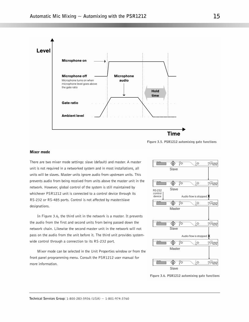
Mixer mode
There are two mixer mode settings: slave (default) and master. A master
unit is not required in a networked system and in most installations, all
units will be slaves. Master units ignore audio from upstream units. This
prevents audio from being received from units above the master unit in the
network. However, global control of the system is still maintained by
whichever PSR1212 unit is connected to a control device through its
RS-232 or RS-485 ports. Control is not affected by master/slave
designations.
In Figure 3.6, the third unit in the network is a master. It prevents
the audio from the first and second units from being passed down the
network chain. Likewise the second master unit in the network will not
pass on the audio from the unit before it. The third unit provides system-
wide control through a connection to its RS-232 port.
Mixer mode can be selected in the Unit Properties window or from the
front panel programming menu. Consult the PSR1212 user manual for
more information.
Technical Services Group: 1-800-283-5936 (USA) ~ 1-801-974-3760
15Automatic Mic Mixing ~ Automixing with the PSR1212
Microphone on
Microphoneaudio
Holdtime
Microphone off
Ambient level
Gate ratio
Microphone turns on when
microphone level goes above
the gate ratio
Time
Level
Figure 3.5. PSR1212 automixing gate functions
Figure 3.6. PSR1212 automixing gate functions

Gating groups
In addition to specifying gating characteristics for
each mic input, you can assign the inputs to a gating
group for greater flexibility and control. When
inputs are assigned to a gating group, the gating
information from the inputs is used to control how
the entire mixer behaves.
The PSR1212 features four internal gating
groups (Internal 1–4) and four global gating
groups across the expansion bus (Global A–D).
Microphones can only be used in one gating group
at a time. If an input is not assigned to a gating
group, that mic’s gate properties are independent
and have no effect on any other gating group.
When gating groups span two or more units (global gating groups), the group settings must be the same for each unit in
the global gating group. Mic inputs are routed to Global Group A by default.
• Max # Mics. This sets the maximum number of microphones that can be gated on at any one time within a
gating group. For internal groups, the maximum number of mics can be from 1 to 8. For global groups the
maximum number of mics will vary depending on how many mic inputs are assigned to the gating group (up to
64). You can also select All for the global groups—which means all mics could gate on.
• 1st Mic Priority. This setting helps maintain maximum audio intelligibility by allowing only one mic to gate on
to a participant’s voice. 1st Mic Priority allows more than one microphone to be activated at same time—it
simply restricts mics from gating on to the same audio source. It does this by determining the audio level
received by all mics when the first mic is gated on. This audio level is then used as the ambient level for the
gating group. If this feature is disabled, usually two or more microphones gate on when only one person speaks.
• Last Mic Mode list. There are two options for Internal groups: Last On and Off. If you are configuring Global
groups, you can select from the mic inputs assigned to the Global group in addition to Last On and Off.
Last On leaves the mic that was activated last full on until another mic input is gated on. The Input setting
allows you to select which mic input the PSR1212 leaves on when all mics gate off. In a boardroom or meeting
room application, this feature can be used to specify the chairperson’s mic as the last mic on. If Off is selected,
all mics will gate off when no audio is present.
Technical Services Group: 1-800-283-5936 (USA) ~ 1-801-974-3760
16 Automatic Mic Mixing ~ Automixing with the PSR1212
Figure 3.7. PSR1212 automixing gate functions
Technical Services Group: 1-800-283-5936 (USA) ~ 1-801-974-3760
17Automatic Mic Mixing ~ Automixing with the PSR1212
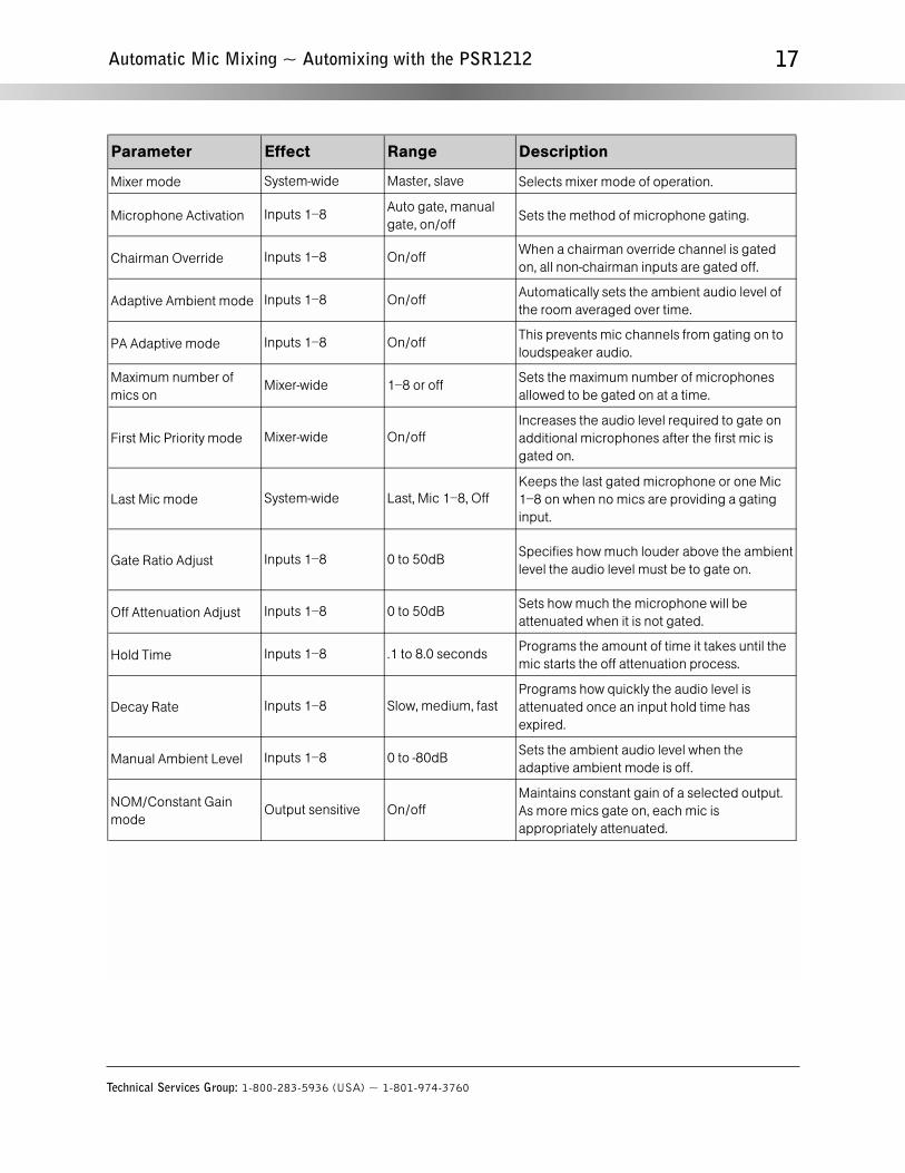
Parameter Effect Range Description
Mixer mode System-wide Master, slave Selects mixer mode of operation.
Microphone Activation Inputs 1–8Auto gate, manual
gate, on/offSets the method of microphone gating.
Chairman Override Inputs 1–8 On/offWhen a chairman override channel is gated
on, all non-chairman inputs are gated off.
Adaptive Ambient mode Inputs 1–8 On/offAutomatically sets the ambient audio level of
the room averaged over time.
PA Adaptive mode Inputs 1–8 On/offThis prevents mic channels from gating on to
loudspeaker audio.
Maximum number of
mics onMixer-wide 1–8 or off
Sets the maximum number of microphones
allowed to be gated on at a time.
First Mic Priority mode Mixer-wide On/off
Increases the audio level required to gate on
additional microphones after the first mic is
gated on.
Last Mic mode System-wide Last, Mic 1–8, Off
Keeps the last gated microphone or one Mic
1–8 on when no mics are providing a gating
input.
Gate Ratio Adjust Inputs 1–8 0 to 50dBSpecifies how much louder above the ambient
level the audio level must be to gate on.
Off Attenuation Adjust Inputs 1–8 0 to 50dBSets how much the microphone will be
attenuated when it is not gated.
Hold Time Inputs 1–8 .1 to 8.0 secondsPrograms the amount of time it takes until the
mic starts the off attenuation process.
Decay Rate Inputs 1–8 Slow, medium, fast
Programs how quickly the audio level is
attenuated once an input hold time has
expired.
Manual Ambient Level Inputs 1–8 0 to -80dBSets the ambient audio level when the
adaptive ambient mode is off.
NOM/Constant Gain
modeOutput sensitive On/off
Maintains constant gain of a selected output.
As more mics gate on, each mic is
appropriately attenuated.

Technical Services Group: 1-800-283-5936 (USA) ~ 1-801-974-3760
18

CHAPTER 4: Audio Routing
Matrix Mixing
One of the more important functions of the PSR1212 is matrix routing of audio signals. Like all device functions, routing
is executed in the digital domain. Routing is configured using G-Ware and a direct connection between a PC and the
PSR1212 unit. Changes in routing can be executed via the RS-232 port and/or via presets on the control/status connector.
The PSR1212 audio matrix has 32 input and 32 output destinations, with level control at each cross point. Custom
labels can be configured for each input and output. Inputs and outputs to the matrix are described on the next page.
Technical Services Group: 1-800-283-5936 (USA) ~ 1-801-974-3760
Audio Routing ~ Matrix Mixing
Figure 4.1. Default routing in the Matrix Screen

Technical Services Group: 1-800-283-5936 (USA) ~ 1-801-974-3760
20 Audio Routing ~ Matrix Mixing
Inputs
• Gated and Non-gated Inputs 1–8. Inputs 1–8 (selectable for mic or line level) are located on the rear terminal
block. Both gated and non-gated inputs are provided on the matrix for delivery to desired destinations. This is
provided because, in some applications (such as a courtroom), direct, non-gated outputs are required. Default
routing for gated microphone inputs are to the O-Bus. Non-gated outputs are routed by default to their
corresponding output number (i.e., Input 1 is routed to Output 1).
• Inputs 9–12. These are line level inputs that appear on the rear panel terminal blocks. This is typically audio
that comes from a CD player, VCR, and other auxiliary audio sources. In typical applications, this audio must be
heard in the local PA system (as well as networked PSR1212 units). In the default routing, audio is routed to
every other device except itself.
Outputs
• Outputs 1–8. These are exactly the same as Outputs 9–12. Their default routing is for each non-gated Input 1–8
to go directly to these outputs.
• Outputs 9–12. These are line level outputs that appear on the rear panel terminal blocks. This is typically audio
that goes to a power amp with speakers, VCR, tape recorder, or other auxiliary audio device. Normally, this
audio contains auxiliary audio and audio from other networked PSR1212 units. In the default routing, Inputs
9–12 (minus your channel input) and master auxiliary mix (all auxiliary audio from other PSR1212 units) are
contained in this audio.
Expansion bus O–Z
Audio on any PSR unit in the E-bus network can be placed on the bus or taken off the bus and routed to any destination
within the unit. The PSR1212 has 12 digital mix-minus buses:
• O–R buses are defaulted as the mic mix buses and can communicate the NOM count. Gated mics are default
routed to the O bus.
• S–Z buses are defaulted as the auxiliary mix buses. They are used to carry auxiliary audio such as that from
VCRs and CD players. These buses are used as mic mix buses when NOM count is not required.
Processing A–H
There are eight processing blocks on the PSR1212 (Processing A–H). With these processing channels, you can apply
filters, EQ, or other processing settings to an input or a group of inputs which can then be routed to a single output or
group of outputs. These buses are typically used to reduce feedback in the venue and provide crossovers for different
speaker systems.
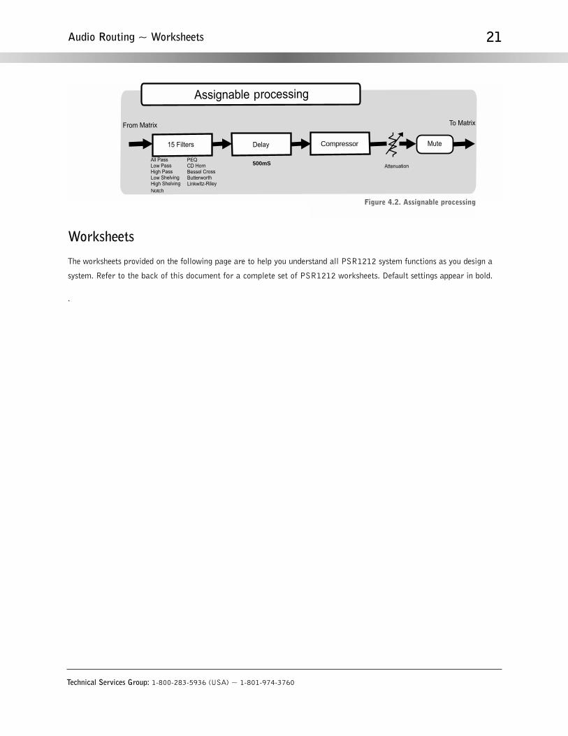
Worksheets
The worksheets provided on the following page are to help you understand all PSR1212 system functions as you design a
system. Refer to the back of this document for a complete set of PSR1212 worksheets. Default settings appear in bold.
.
Technical Services Group: 1-800-283-5936 (USA) ~ 1-801-974-3760
21Audio Routing ~ Worksheets
500mS
Notch
Compressor
p
Figure 4.2. Assignable processing

Technical Services Group: 1-800-283-5936 (USA) ~ 1-801-974-3760
22 Audio Routing ~ Worksheets
Program Parameter Selection RangeMaster, Slave
RS-232 Baud Rate 9.6, 19.2, 38.4, 57.6, 115.2 kbps
RS-232 Flow Control
Modem Mode
Clear Modem PasswordInput/Output Channel 1-12 (Out 12)
1 2 3 4 A B C D
Hints:
E1 Each Expansion Bus PA Adapt reference can only be defined once across the system (all linked PSR1212s).
E2 Before defining, verify that the given reference has not already been defined on another unit.
E3 See the Input - Output Parameters worksheet(s) to define a PA Adapt reference to a local output on this unit.
E4
Define PA Adapt Expansion Bus ReferencesReference #: Define as Output: (1-12) On Unit: (Device ID 0-7)
ClearO
ne PS
R1212
Program Parameter Selection Range
Timeout 0 - 15 (5) Mixer Mode
Lock Front Panel
Set Passcode
Date
On, Off
On, Off
Internal/Unit Mixer Groups
Device ID No.
Unit ID No.
Mixer Group Parameters
0 - 7
Factory Programmed
Program Parameter Selection Range
Maximum No. of Mics Off, 1-8 (4)
PSR1212 System Parameters Worksheet
On, Off
Last On, Off, Mic 1 - Mic 8
On, Off
Any 5 Front Panel Keys
Systemwide Parameters
Global/Site Mixer Groups
First Mic Priority
Last Mic Mode
Note
Application Notes
Default Meter
Enter
Figure 4.3. System Parameters worksheet
Input Channel 1 2 3 4 5 6 7 8 9 10 11 12Program Parameter Selection Range
Input Type Mic 55dB, Mic 25dB, Line
Phantom Power On, Off
Input Gain Adjust -60dB to +20 dB (0)
AGC On, Off
Mute On, Off
Input Filters 1-4 See Processing Filters Worksheets
Input Activation Auto, Manual
Chairman Mic On, Off
Gate Ratio 0 - 50 dB (15)
Off Attenuation 0 - 50 dB (12)
Hold Time .1 - 8.0 seconds (.3)
Decay Rate Slow, Medium, Fast
Manual Ambient 0dB to -70dB (-30)
Adaptive Ambient On, Off
PA Adaptive Mode On, Off
PA Adapt Reference Output 1-12, Expansion Bus Ref E1-E4 See System Parameters to define E1-E4
Mixer Group Select Internal 1-4 or Global A-D (A) See System Parameters to define Mixers
Output Channel 1 2 3 4 5 6 7 8 9 10 11 12Program Parameter Selection Range
Output Gain Adjust -60dB to 20 dB (0)
Mute On, Off
NOM On or Off
A B C D E F G HProgram Parameter Selection Range
Processing Filters 1-15 See Processing Filters Worksheets
Delay 0-500ms (0ms) .02ms steps
Compressor/Limiter On, Off
Threshold -30dB to +20dB (0dB)
Ratio 1:1 - 1:20
Attack Time 0.5ms to 100ms in 0.5ms steps (1ms)
Release Time 5ms to 2sec. In 5ms (1s)
Processing Attenuation 0dB to -60dB (0dB)
PSR1212 Input/Output Parameters Worksheet
Processing Channel
ClearO
ne PS
R1212
Figure 4.4. Input/Output Parameters worksheet

CHAPTER 5: System ControlThe PSR1212 provides a variety of options for system control. You can create up to 32 presets and up to 255 macros to
change whole room configurations or run a series of commands. Presets, macros, and commands can be executed using
any of the following control options: custom control through Control/Status port A, contact closure through Control/Status
port B, ClearOne Control Panels or XAP IR Remote through the RS-485 ports, serially with a touch panel, modem, or PC
through the RS-232 port, or front panel LCD menus.
Presets and Macros
A preset is simply a group of routing and configuration settings stored in the PSR1212. These settings are applied to the
unit when the preset is executed. A good way to think of presets is to consider each preset as a room configuration option.
You can create up to 32 presets which enables you to accommodate changing room requirements quickly and efficiently.
PSR1212 presets are unique in the sense that they operate independently of other presets in the unit. When a preset is run,
only the selected inputs/outputs are changed—all other settings in other presets remain unchanged and are not reset. This
means you can change audio routing and configuration settings in a room without affecting settings in other rooms (such
as gain).
Presets can be executed in a variety of different ways including the Execute Preset utility in G-Ware, the front
panel controls of the PSR1212, RS-232 external control devices, RS-485 control devices (ClearOne Control Panel and
XAP IR Remote), logic in/out, and contact closure. You can also create macros which can run multiple presets. These
options give you tremendous flexibility when designing your installations and are described in more detail in the
PSR1212 Installation and Operation manual.
Macros provide powerful options for controlling and operating your PSR1212. A macro can contain multiple
commands that can reference a single unit or multiple units across the expansion bus. Each PSR1212 is designed to
support up to 255 macros, with an average of 150 command lines each. Macros are created in G-Ware using the Macro
Recorder, which records your onscreen selections, or the Macro Editor, which allows you to directly create command lines.
The Macro Editor is also used to edit macros created using the Macro Recorder. For more information on creating and
using macros, consult the PSR1212 Installation and Operation manual.
Technical Services Group: 1-800-283-5936 (USA) ~ 1-801-974-3760
System Control ~ Control and Status

Technical Services Group: 1-800-283-5936 (USA) ~ 1-801-974-3760
24 System Control ~ Control and Status Connectors
Control and Status Connectors
Control/Status connections are provided on two DB-25 connectors. These connectors are labeled Control/Status A and
Control/Status B and contain different types of pins. Control pins on Control/Status A are momentary while control pins on
Control/Status B are latching. The inputs on these connectors are internally pulled high and are activated by connecting the
pin to ground. The outputs are open collectors, which are open when inactive and grounded when active. This allows the
PSR1212 to control and be controlled by a wide variety of external devices, including relays, lamps, switches, and other
equipment.
Control/Status A
The GPIO (general-purpose input/output) Builder in G-Ware is used to establish the pin assignments for the 16 user
definable pins on Control/Status Port A. These pins provide control via contact closure and status via open collector
functions in the unit. Note that the pins numbered in blue are command pins; the pins numbered in green are status pins.
The default pin assignments are listed on page 26.
Control/Status B
The Control/Status B port is designed to run presets. Using the Preset Mask Control
Status B in the Preset window, you can require an active high (H) or active low (L)
contact on a control pin (1–19 odd numbers) or combination of several contacts in
order to run the preset.
A typical use for Preset Mask Control Status B is a room combining application which uses automatic partitions
with sensors or triggers which set the pin to high (H) when the partition is closed and to low (L) when the partition is
open. For example, if pin 1 is connected to the first partition and pin 3 is connected to the second partition, then the
Preset Mask Control Status B settings shown in Figure 5.2 will activate the preset when the first partition is open and
the second partition is closed.
Figure 5.1. Customizing pin assignments with GPIO Builder
Figure 5.2. Preset MaskControl/Status B

Technical Services Group: 1-800-283-5936 (USA) ~ 1-801-974-3760
25System Control ~ Control and Status Connectors
Mute
All
Combined
All
Separate
1 + 2
3 + 4
1 + 2 + 3
4
VOLUME
Control
Status
Room combining
All separate
All combined
1 + 2 : 3 + 4
1 + 2 + 3 : 4Status
+5VDC
LED
Status
+5VDC
LED
Status
+5VDC
LED
Status
+5VDC
LED
Volume
up
Volume
down
Mute
Control
status
Status
+5VDC
LED
Room combining controlsControls for each room
Figure 5.4. Room combining using control/status pins
Command
Status
Control/Status
Connector
+5VDC@300mA
LED
Figure 5.3. Direct control/status operation

Technical Services Group: 1-800-283-5936 (USA) ~ 1-801-974-3760
26 System Control ~ Control and Status Connectors
Pin Definable Type Default Description Pin Definable Type Default Description
1 Yes Control Lock front panel toggle 1 Yes Control Preset select bit
2 Yes Status Status of front panel lock 2 Yes Status Preset select status (Pin 1)
3 Yes Control Mute all mics toggle 3 Yes Control Preset select bit
4 Yes Status Status of mute all mics 4 Yes Status
5 Yes Control Mute Output 9 toggle 5 Yes Control
6 Yes Status Status of Output 9 mute 6 Yes Status
7 Yes Control Mute Output 10 toggle Yes Control
8 Yes Status Status of Output 10 mute 8 Yes Status
9 Yes Control Mute Output 11 toggle 9 Yes Control
10 Yes Status Status of Output 11 mute 10 Yes Status
11 Yes Control Mute Output 12 toggle 11 Yes Control
12 Yes Status Status of Output 12 mute 12 Yes Status
13 Yes Control Output 1 volume up (1dB) 13 Yes Control
14 Yes Status Not programmed 14 Yes Status
15 Yes Control Output 1 volume down (1dB) 15 Yes Control
16 Yes Status Not programmed 16 Yes Status
17 No Status Mic 1 gate status 17 No Status
18 No Status Mic 2 gate status 18 No Status
19 No Status Mic 3 gate status 19 No Status
20 No Status Mic 4 gate status 20 No Status
21 No Status Mic 5 gate status 21
22 No Status Mic 6 gate status 22
23 No Status Mic 7 gate status 23 No +5VDC
24 No Status Mic 8 gate status 24 No +5VDC
25 No Ground Ground 25 No Ground Ground
Control/Status B
No Connection
No Connection
Control/Status A
7
Preset select status (Pin 3)
Preset select bit
Preset select status (Pin 5)
Preset select bit
Preset select status (Pin 7)
Preset select bit
Preset select status (Pin 9)
Preset select bit
Preset select status (Pin 11)
Preset select bit
Preset select status (Pin 13)
Preset select bit
Preset select status (Pin 15)
Preset select bit
Preset select status (Pin 17)
Preset select bit
Preset select status (Pin 19)
Figure 5.5. Default pin programming

ClearOne Control Devices
ClearOne manufactures three control devices designed for use with the PSR1212: Volume Control Panel, Select Control
Panel, and XAP IR Remote Control. These devices are programmed using the Remote Builder in G-Ware. These control
devices are connected to Remote Panel A or Remote Panel B—the RS-485 connectors.
Volume and Select Control Panels
ClearOne Control Panels are convenient wall panels which provide control over the PSR1212 system. There are two
Control Panel models: Volume and Select. Volume has three programable buttons that were primarily designed to control
gain and mute but can be programmed with any command. It also has eight LEDs that can be programmed to indicate
certain gain levels or muting. As with the buttons, these LEDs can be programmed to represent any command status. The
Select Control Panel can be programmed to execute various commands such as presets for room combining applications.
You can connect up to six Control Panels in daisy chain fashion to each RS-485 port.
XAP IR Remote
The XAP IR Remote provides remote control of volume and mute for a PSR system. You can connect up to two XAP IR
Remote Controls—one to each RS-485 port. See the XAP IR Remote user manual for more information. The XAP IR
Remote has five programmable buttons and one programmable LED.
Technical Services Group: 1-800-283-5936 (USA) ~ 1-801-974-3760
27System Control ~ ClearOne Control Devices
Figure 5.6. Volume (left)and Select Control Panels
Figure 5.7. XAP IR Remote
Figure 5.8. Programming a Volume Panel in Remote Builder

Technical Services Group: 1-800-283-5936 (USA) ~ 1-801-974-3760
28 System Control ~ Serial Control (RS-232)
Serial Control (RS-232)
Operation of linked PSR1212 units can be done with one RS-232 serial connection. Functions which can be controlled via
this connection include audio level control, muting, audio signal routing, telephone dialing, remote diagnostics, and many
other functions.
While any external device with an RS-232 serial connection can communicate with the PSR1212, the system was
designed primarily to be programmed and set up using G-Ware, and operated using a custom remote controller.
The PSR1212 provides real-time control and status via the RS-232 port of all system functions, including:
• Input and output audio levels in dBu
• Input and output gain in dB
• Channel input and output muting control and status
• Mic/line input select and phantom power on/off control and status
• Microphone gate activation status
• Control and status of AGC and equalization
• Routing
• Automixing functions and modes
• Control/Status connector configurations
• Preset/macro configurations
• Password protection
• Expansion bus setup
• System setup

Front Panel
The PSR1212’s front panel is intuitive to operate, thanks to its simple interface: a 2x16 character LCD, menu buttons,
and a peak-level LED bar meter. Although most of the PSR1212’s features are programmed with G-Ware software, the
front panel can be used for simple adjustments and meter monitoring.
To prevent unauthorized changes, the PSR1212 can be password protected. When the unit is locked, navigation of the
menus is allowed without a password; however, changes to programming require a valid password.
LCD menu tree
The menu tree features five main menus, each with submenus. These branches typically end when an adjustable parameter
or viewable value is reached. The diagram below shows the LCD menu tree.
The five main menus are: System, RS-232, Meter, Inputs, and Outputs. All submenu items are arranged under these
menus. Use the Enter button to select items and the and buttons to scroll through menus and submenus. When the
last menu item is reached, the display scrolls back to the beginning of the list. The Esc button allows you to back out of the
menus.
Technical Services Group: 1-800-283-5936 (USA) ~ 1-801-974-3760
29System Control ~ Front Panel
Figure 5.9. LCD menu tree

Technical Services Group: 1-800-283-5936 (USA) ~ 1-801-974-3760
30

CHAPTER 6: PSR1212 Connections
System Connections
Audio connections
The PSR1212 utilizes removable Phoenix block connectors that are supplied with the unit. To connect, standard audio
cables should be stripped and inserted into the terminal block. The terminal screw in the block is then tightened, providing
a secure and reliable audio connection. The terminal block can then be inserted into the rear panel connectors. These
connectors maximize reliability and ease of use.
Control/Status connections
Direct remote control and status outputs are provided on two DB-25 connectors on the rear of the PSR1212.
Expansion Bus connection
The expansion bus consists of two RJ-45 connectors. An 18" cable is provided. Additional expansion bus cables are
available.
Serial RS-232
The serial RS-232 communications port is connected via a standard DB-9 connector. The RS-232 baud rate can be
programmed for 9,600, 19.2K, 38.4K, or 57.6K baud rate. Flow control can be set for either hardware or none.
Passcodes
To prevent unwanted access via the front panel or modem, the unit can be programmed to require a passcode. The
RS-232 password is set from a PC. Should the RS-232 password be forgotten, it can be reset from the front panel.
Meters
The PSR1212 has an LED meter and an LCD. Whenever the input, output, or room loss menus are accessed, the meter
displays the level of the parameter selected. When not in the input, output, or room loss menus, the default meter is shown.
The default meter can be changed to any input, output, or room loss parameter by pressing the Meter button.
Technical Services Group: 1-800-283-5936 (USA) ~ 1-801-974-3760
PSR1212 Connections ~ System Connections

Power
A universal power connector is provided. The PSR1212 will operate on all global voltages and cycles.
Expansion Bus Connections
Communication functions of the expansion bus
The expansion bus is a high-speed network protocol that provides two primary system functions: 1) communications among
units, and 2) audio linking. All functions of the PSR1212 are available across a system of linked PSR1212 units, which
allows automixing of up to eight PSR1212 units, 64 microphones, and 32 line inputs.
The PSR1212 takes advantage of its DSP infrastructure in accomplishing this task. Networked PSR1212 units
communicate to one another via the expansion bus (see Figure 6.1). Control, status, and addressing functions are
performed via the network bus. To accomplish this, configure the first PSR1212 as the Master unit. All additional
units are then programmed as Slaves. The master unit then provides communication supervision for all other units on
the network.
Serial connection to the master PSR1212 permits programming, operation and diagnostics to all PSR1212 units
networked together. This permits a single connection for the installer and user, decreasing costs and complexity.
Technical Services Group: 1-800-283-5936 (USA) ~ 1-801-974-3760
32 PSR1212 Connections ~ Expansion Bus Connections
Mics 1-8
All Mics except 1-8
O - Bus
Expansion
Bus
PSR1212 Unit 0 PSR1212 Unit 1 PSR1212 Unit 2
Mics 17-24Mics 9-16
All Mics except 9-16 All Mics except 17-24
Routing Matrix
Unit #1
Routing Matrix
Unit #2
Routing Matrix
Unit #3
Up to 8 PSR1212 units
for a total of 64 mic inputs
Out 1 Out 1Out 1
Figure 6.1. Mix-minus configuration of the O bus
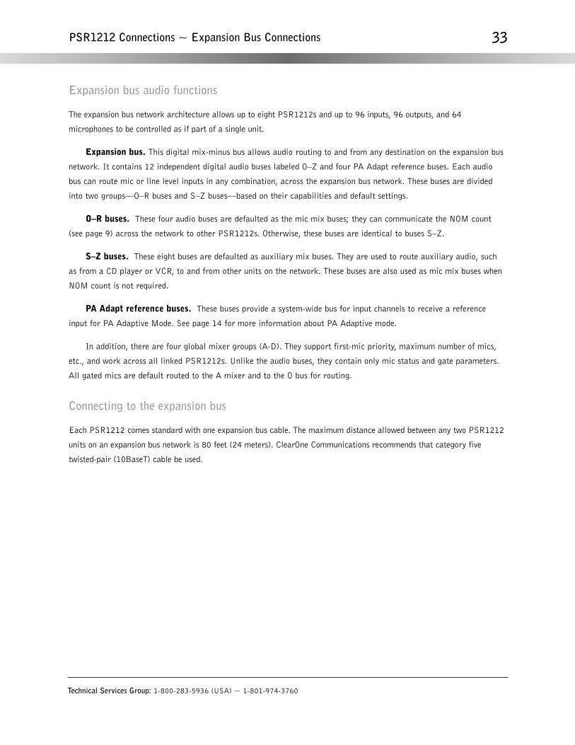
Expansion bus audio functions
The expansion bus network architecture allows up to eight PSR1212s and up to 96 inputs, 96 outputs, and 64
microphones to be controlled as if part of a single unit.
Expansion bus. This digital mix-minus bus allows audio routing to and from any destination on the expansion bus
network. It contains 12 independent digital audio buses labeled O–Z and four PA Adapt reference buses. Each audio
bus can route mic or line level inputs in any combination, across the expansion bus network. These buses are divided
into two groups—O–R buses and S–Z buses—based on their capabilities and default settings.
O–R buses. These four audio buses are defaulted as the mic mix buses; they can communicate the NOM count
(see page 9) across the network to other PSR1212s. Otherwise, these buses are identical to buses S–Z.
S–Z buses. These eight buses are defaulted as auxiliary mix buses. They are used to route auxiliary audio, such
as from a CD player or VCR, to and from other units on the network. These buses are also used as mic mix buses when
NOM count is not required.
PA Adapt reference buses. These buses provide a system-wide bus for input channels to receive a reference
input for PA Adaptive Mode. See page 14 for more information about PA Adaptive mode.
In addition, there are four global mixer groups (A-D). They support first-mic priority, maximum number of mics,
etc., and work across all linked PSR1212s. Unlike the audio buses, they contain only mic status and gate parameters.
All gated mics are default routed to the A mixer and to the O bus for routing.
Connecting to the expansion bus
Each PSR1212 comes standard with one expansion bus cable. The maximum distance allowed between any two PSR1212
units on an expansion bus network is 80 feet (24 meters). ClearOne Communications recommends that category five
twisted-pair (10BaseT) cable be used.
Technical Services Group: 1-800-283-5936 (USA) ~ 1-801-974-3760
33PSR1212 Connections ~ Expansion Bus Connections

Technical Services Group: 1-800-283-5936 (USA) ~ 1-801-974-3760
34

CHAPTER 7: Applications
The sophistication and adaptability of the PSR1212 allow it to control and enhance many sound applications. Following
are nine applications where the PSR1212 forms the centerpiece of a high-quality sound reinforcement or room-combining
system.
There are numerous other applications where the PSR1212 can control and enhance the audio experience. The
principles used in the applications outlined here carry over into other applications.
Auditorium Installation
A typical auditorium application requires the use of multiple inputs and outputs, as well as audio equalization and signal
delay, to provide a pleasing audio experience. The PSR1212 handles these tasks perfectly.
The auditorium diagram (Figure 7.1) illustrates a typical auditorium layout, with locations of microphones,
speakers, and seating areas. Typical audio scenarios include on-stage speaking; singing and/or musical instruments; and
pre-recorded music sourced from a CD or tape player. You can configure a preset for each scenario, using the
PSR1212’s filters to tailor the sound for a natural, balanced response.
Auditorium applications using constant directivity horn speakers located high at the front of the room are
enhanced with the PSR1212’s CD Horn EQ. This feature compensates for the inherent 6dB/octave high frequency
rolloff typical of CD horn drivers. You can program this function for each preset you use for auditorium applications.
Audience members seated underneath the balcony are shielded from some of the output from the horn speakers
located at the front of the room. To compensate, fill speakers are used in the ceiling underneath the balcony overhang
(see Figure 8.1). To eliminate the imbalance caused by sound reaching a listener’s ears at different times from the fill
speakers and the horn speakers, you can program the PSR1212 to introduce a delay to the fill speakers. The
PSR1212’s G-Ware software can calculate distances in feet and meters to help establish the amount of delay required.
Technical Services Group: 1-800-283-5936 (USA) ~ 1-801-974-3760
Applications ~ Auditorium Installation

Technical Services Group: 1-800-283-5936 (USA) ~ 1-801-974-3760
36 Applications ~ Auditorium Installation
MicrophonesPC (for set up;
not necessary for
system operation)
Fill speakers
PSR1212
Logic Out
Status and
Control
Horn cluster
Right spkrLeft spkr Floor short Floor long Balcony
CD
Control
Panel
(optional)
Tape RecorderPower Amp
Auditorium
Main floorseating area
Balcony
Stage
3-horn speaker cluster
at front
Ceiling (fill) speakers
Microphones
1 floor short
1 balcony
1 floor long
Left/rightspeakersat front
Figure 7.1. Typical auditorium layout
Figure 7.2. Auditorium installation diagram

Technical Services Group: 1-800-283-5936 (USA) ~ 1-801-974-3760
37Applications ~ Arena Installation
Arena Installation
Arenas present numerous acoustical challenges, including high ambient sound levels and generally poor acoustical
characteristics. The PSR1212 can help adapt the sound system to challenging acoustical environments.
The multitude of sound requirements in an arena is perfect for taking advantage of the PSR1212’s expansion bus
technology, which allows multiple PSR1212s to be linked and operated as a single unit. The arena diagram (Figure 7.3)
and the arena installation diagram (Figure 7.4) illustrate the PSR1212’s ability to distribute balanced audio to the main
arena area, the fill locations underneath balcony or upper bowl areas, and concession areas located outside the arena.
During a typical sports event, you might want to use a PSR1212 preset configured to send the announcer’s voice to
the central speaker array (with the CD Horn EQ enabled), with a delayed signal sent to the fill speakers. Rally music,
either pre-recorded or from an instrument such as an organ, can be routed to the same speakers, with various filters
configured to enhance the audio quality of the source. The concession area speakers are used to announce countdown to
game time and other information to people outside the main arena area.
Configure a preset for halftime entertainment that routes several microphones and live or pre-recorded music to
the central speaker cluster and fill speakers, with microphone mix, delay, filter, and EQ settings configured for balanced
audio response.
Arena
Concession area
Speakers in concession area
COURT
Fill speakers
underneath
overhang
Seating
Balcony with
overhang
Hanging
speaker
cluster
Figure 7.3. Arena layout

Movie Theater Installation
A properly designed and calibrated sound system makes all the difference in the enjoyment of a film or movie presentation.
Unlike many other audio application scenarios, movie theaters are designed to exhibit good acoustic properties. Most
sound system calibrations center around creating a broad, flat, high-fidelity audio response throughout the seating area.
A multiple-channel theater surround sound system is shown in Figure 7.5, and a connection diagram is shown in
Figure 7.6. The PSR1212 can customize the response of each loudspeaker through the use of parametric equalizers,
filters, and compressors designed to compensate for speaker and room characteristics and deficiencies. A complete
description of these adjustable parameters (and how to configure them) is found in the PSR1212 Installation and
Operation Manual.
A CD player and tape deck can be connected to play background music between movies—over both the theater and
lobby speaker systems, and a microphone can be used to facilitate the occasional announcement.
Microphones
PC (for set up;
not necessary for
system operation)
Logic Out
Status and
Control
Control
Panel
(optional)
PSR1212
Concession area speakers
Expansion Bus
terminator
Organ
Hanging speaker cluster
Mics
Mics
East Zone
West Zone
North Zone
South Zone
Main arena
fill speakersSubwoofers Horns
CD
VCRVCR
Tape Recorder
Power Amp Power Amp
PSR1212Expansion Bus
Expansion
Bus terminator
Power Amp
Technical Services Group: 1-800-283-5936 (USA) ~ 1-801-974-3760
38 Applications ~ Movie Theater Installation
Figure 7.4. Arena installation

Technical Services Group: 1-800-283-5936 (USA) ~ 1-801-974-3760
39Applications ~ Movie Theater Installation
Movie theater surround system
Seating area
Dialogue
speaker
Left frontLeft rear
Left center
Right frontRight rear
Right center
Subwoofer
Screen
Projector
Figure 7.5. Movie theater layout
Microphone
PC (for set up;
not necessary for
system operation)
Logic Out
Status and
Control
Control
Panel
(optional)
Lobby speakers
PSR1212
Projector
SubwooferLeft rear
Right rear
Left center
Right center
Dialogue
Left front
Right front
VCRCD
Tape Recorder
Power AmpPower Amp
Surround Sound Processor
Power Amp
Figure 7.6. Movie theater installation

Gymnasium Installation
Gymnasium sound systems are called upon to meet the needs of a variety of scenarios, from sports announcing to meetings
to student skits and productions. In all cases, the PSR1212 can adapt the sound system to accommodate the demands
required.
For general announcing or presentations, such as for games or assemblies, presets can be configured for one or
more microphones, with mixing and gating, if desired.
More elaborate configurations would use the PSR1212’s parametric equalizers and filters to create better sound
fidelity from live or pre-recorded music played over horn speakers typically used in gymnasiums. An example would be
establishing a preset for halftime performances, where the equalizers and filters are configured to provide stronger low-
frequency response from music sources.
Technical Services Group: 1-800-283-5936 (USA) ~ 1-801-974-3760
40 Applications ~ Gymnasium Installation
Gymnasium
Court
Seating
Hanging
speaker
cluster
Announcer table
Microphone
Figure 7.7. Gymnasium
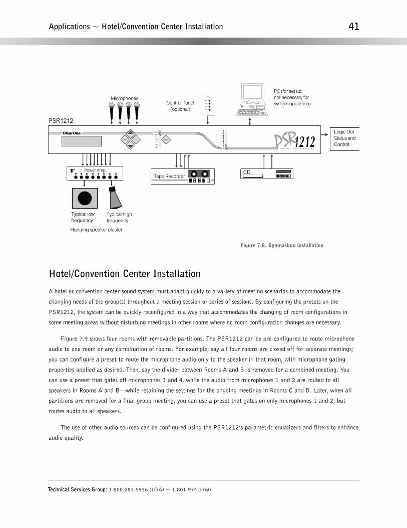
Technical Services Group: 1-800-283-5936 (USA) ~ 1-801-974-3760
41Applications ~ Hotel/Convention Center Installation
Hotel/Convention Center Installation
A hotel or convention center sound system must adapt quickly to a variety of meeting scenarios to accommodate the
changing needs of the group(s) throughout a meeting session or series of sessions. By configuring the presets on the
PSR1212, the system can be quickly reconfigured in a way that accommodates the changing of room configurations in
some meeting areas without disturbing meetings in other rooms where no room configuration changes are necessary.
Figure 7.9 shows four rooms with removable partitions. The PSR1212 can be pre-configured to route microphone
audio to one room or any combination of rooms. For example, say all four rooms are closed off for separate meetings;
you can configure a preset to route the microphone audio only to the speaker in that room, with microphone gating
properties applied as desired. Then, say the divider between Rooms A and B is removed for a combined meeting. You
can use a preset that gates off microphones 3 and 4, while the audio from microphones 1 and 2 are routed to all
speakers in Rooms A and B—while retaining the settings for the ongoing meetings in Rooms C and D. Later, when all
partitions are removed for a final group meeting, you can use a preset that gates on only microphones 1 and 2, but
routes audio to all speakers.
The use of other audio sources can be configured using the PSR1212’s parametric equalizers and filters to enhance
audio quality.
Microphones
PC (for set up;
not necessary for
system operation)
Logic Out
Status and
Control
PSR1212
Control Panel
(optional)
Hanging speaker cluster
Typical low
frequency
Typical high
frequency
CDTape Recorder
Power Amp
Figure 7.8. Gymnasium installation

Technical Services Group: 1-800-283-5936 (USA) ~ 1-801-974-3760
42 Applications ~ Hotel/Convention Center Installation
PC (for set up;
not necessary for
system control)
Logic Out
Status and
Control
Speakers
PSR1212
Mics
Mics
Room A Room B Room C Room D
Control Panels (optional)
CDVCRVCRPower Amp
Hotel/convention center
Speaker A
Room A
Room B
Room C
Room D
Speaker B
Speaker C
Mic 2
Mic 4
Mic 6
Mic 1
Mic 3
Mic 5
Speaker D
Mic 7 Mic 8
Removable
room partition
Removable
room partition
Removable
room partition
Control Panel
Control Panel
Control Panel
Control Panel
Figure 7.9.Hotel/convention center
Figure 7.10. Hotel/convention center installation

Technical Services Group: 1-800-283-5936 (USA) ~ 1-801-974-3760
43Applications ~ Conference Room Installation
Conference Room Installation
Figure 7.11 shows a conference room area with a main meeting area and six smaller meeting rooms adjoining the main
area. The PSR1212 enhances the flow of audio between the main meeting area and the adjoining small rooms, and can
also facilitate exclusive communication between the small rooms.
Scenarios where these kinds of audio flow are necessary include team-building exercises, where participants meet
in smaller groups and then report progress to the main meeting area. Another scenario is one in which emergency
officials from various agencies assemble in the main meeting area to coordinate response activities to an emergency.
These officials convene in the smaller rooms as needed to assess needs and troubleshoot problems at the agency level
while remaining accessible to the main meeting area.
A PSR1212 preset could be established to give gating priority to the podium microphone in the main meeting
area, with audio routed between rooms as desired to provide a seamless communication flow.
Conference room
Main meeting area
Podium with microphone
Ad
join
ing
sm
all
roo
ms
Ad
join
ing
sm
all ro
om
s
Mic
Mic
Mic
Mic
Mic
Mic
Ceiling speaker
Ceiling speaker
Ceiling speaker
Ceiling speaker
Ceiling speaker
Ceiling speaker
Seating
Seating
Seating
Seating
Conference table
Conference table
Conference table
Conference table
Conference table
Conference table
Ceiling speaker
Ceiling speaker
Ceiling speaker
Ceiling speaker
Ceiling speaker
Ceiling Speaker
Screen
Zone 1
Zone 2
Zone 3
Zone 4
Zone 5
Zone 6
— Zone 9 —
— Zone 8 —
— Zone 7 —
Control Panel
Figure 7.11. Conference room

Training Room Installation
In a typical training room application, microphone audio from the trainer is the primary source of audio. A wireless mic is
normally used. Secondary audio is often provided through presentation segments sourced from a VCR or CD player. In
larger training room settings, participants often use desktop microphones to enable all to hear questions and comments.
Figure 7.13 shows a scenario including a wireless lapel mic for the trainer; desktop mics for participants; ceiling
speakers to carry voice (primary) audio and some secondary audio; and left and right speakers at the front of the room,
which carry primary and secondary audio.
Microphone mixing and gating parameters can be set to favor the trainer’s mic to facilitate effective dialogue in
the room. When a particular microphone gates on, nearby speakers can be set to reduced volume or muted to reduce
feedback. Also, participant microphones can be set to gate off when secondary audio sources are in use.
The left and right speakers at the front of the room can be configured to provide stereo sound from a (stereo)
secondary audio source, enhancing the training experience. All speakers can be optimized to produce full-fidelity audio
by programming the PSR1212’s parametric equalizers and filters accordingly.
Technical Services Group: 1-800-283-5936 (USA) ~ 1-801-974-3760
44 Applications ~ Training Room Installation
Mics
PC (for set up;
not necessary for
system operation)
Logic Out
Status and
Control
Control Panels
(optional)
PSR1212
Speakers
Mics
Zone 6
Zone 1
Zone 2
Zone 3
Zone 4
Zone 5 Zone 7
Zone 8 Zone 9
Speakers
CDVCRVCR
Power Amp
Power Amp
Figure 7.12. Conference room installation

Technical Services Group: 1-800-283-5936 (USA) ~ 1-801-974-3760
45Applications ~ Training Room Installation
Training room
Lapel mic
(Mic 1)
Wh
iteb
oa
rd/s
cre
en
Left speaker
Right speaker
Video projector
Desk
DeskDesk Desk
Mic 2
Mic 3
Mic 4
Mic 5
Mic 6
Mic 7
Mic 8
Ceiling speakers
Zone 1
Ceiling speakers
Zone 3
Ceiling speakers
Zone 2
Microphones
PC (for set up;
not necessary for
system operation)
Logic Out
Status and
Control
Ceiling speakers
PSR1212
Mics
Lapel
mic
Lapel mic receiver
Left front Right front
Zone 1 Zone 2 Zone 3
Control
Panel
(optional)
CD VCRVCRPower Amp
Figure 7.13. Training room
Figure 7.14. Training room installation

Boardroom Installation
A boardroom application is a good example of a situation where microphone mixing and gating become critical to
providing seamless dialogue between several people seated around a large table. Figure 7.15 shows a boardroom scenario
with eight participants, each with his own microphone and loudspeaker. Also, there are observer seating areas on the
periphery of the room with loudspeakers for monitoring the discussion at the table.
A typical PSR1212 installation involves establishing a preset where the chairman’s microphone (mic 1) is given
gating and override priorities over the other microphones. Also, whenever a given microphone gates on, audio to that
participant’s loudspeaker gates off to prevent feedback, and the volume level of the microphone to adjacent speakers
might be reduced below normal output levels, providing a more comfortable audio level. Various parametric equalizers
and filters can be configured for particular microphones to enhance the voice qualities of regular participants who sit in
assigned seats. All audio is routed to the observation areas at normal levels.
A preset for secondary audio, such as from a VCR or CD player, routes sound to all speakers in the room and gates
off microphones as desired. The PSR1212’s parametric equalizers and filters are configured to enhance audio quality.
Technical Services Group: 1-800-283-5936 (USA) ~ 1-801-974-3760
46 Applications ~ Boardroom Installation
Boardroom
Mic 1
Ceiling speaker
Ceiling speakerCeiling speaker
Ceiling speaker
Mic 5
Mic 7 Mic 3
Mic 2
Mic 4 Mic 6
Mic 8
Speaker 1
Speaker 5
Speaker 7 Speaker 3
Speaker 8 Speaker 2
Speaker 6 Speaker 4
Table
Observer seatingObserver seating
Observer seatingObserver seating
Ceiling speaker/Zone 10
Ceiling speaker/Zone 9
Figure 7.15. Boardroom

Technical Services Group: 1-800-283-5936 (USA) ~ 1-801-974-3760
47Applications ~ Corporate Paging System
Corporate Paging System
A corporate paging system usually consists of several sound distribution zones, typically using 70V speakers, for paging
various departments of an organization or areas within a building. Such systems are often used for playing background
music, particularly in lobby areas.
With the PSR1212, you can establish customized paging zones where various equalizers and filters are configured
to enhance the fidelity of sound in the system. This can help compensate for room acoustical characteristics and
equipment deficiencies to provide a consistent audio response throughout a given zone or combination of zones.
Figure 7.17 depicts a paging system with nine zones. Each zone could have its own preset to facilitate paging only
within the zone. Zones could also be grouped for broader paging capabilities, depending on requirements. A preset
could be configured to page via all zones. This preset would be used to make organization-wide announcements,
including emergency notifications.
Mics
PC (for set up;
not necessary for
system operation)
Logic Out
Status and
Control
Control Panel
(optional)
Tabletop
speakers
PSR1212
Mics
Ceiling
speakers
Zone 9 Zone 10
Spkr 1 Spkr 2 Spkr 4
Spkr 5 Spkr 6 Spkr 7 Spkr 8
Spkr 3
CD VCRVCRPower Amp
Power Amp
Figure 7.16. Boardroom Installation

Technical Services Group: 1-800-283-5936 (USA) ~ 1-801-974-3760
48 Applications ~ Corporate Paging System
PC (for set up;
not necessary for
system operation)
Logic Out
Status and
Control
Paging zone control
(optional)
Speakers
Zone 6
Zone 1
Zone 2
Zone 3
Zone 4
Zone 5 Zone 7
Zone 8 Zone 9
Speakers
Phone/paging
system CDTape Deck
PSR1212
Line level input
Power Amp
Power Amp
Corporate paging system
Front desk phone/
Paging system
Ceiling
speaker
Ceiling
speaker
Cubicles
Conference room
Office
Office
Office
Restrooms
Zone 7
Break roomZone 8
Ceiling speaker
Ceiling speaker
Ceiling speaker
Ceiling speaker
Ceiling speaker
Ceiling speaker
Zone 1
Zone 2
Zone 4
Zone 6
Zone 9
Zone 5
Front lobby
Ceiling speaker
Ceiling speaker
Office
Ceiling speaker
Zone 3
Cubicles
Cubicles
Cubicles
Ceiling
speaker
Ceiling
speaker
Ceiling
speaker
Ceiling
speaker
Ceiling
speaker
Ceiling
speaker
Figure 7.17. Corporate paging system
Figure 7.18. Corporate paging system installation

Dimensions (LxDxH)17.25" x 10.25" x 1.25"43.8 x 26 x 4.5 cm
Weight7 lb/4.5 kg dry12 lb/5.9 kg shipping
Operating Temperature32–100° F/0–38° C
Humidity15% to 80%, non-condensing
Power Input RangeAuto-adjusting100–240VAC; 50/60Hz
Power Consumption30W typical
Expansion Bus In/OutProprietary NetworkRJ-45 (2), 115.2kbps, 110kΩ
impedanceCategory five twisted-pair cable
80' (24 meters) maximum cable length between any two PSR1212s, XAP 800s or XAP 400s
RS-232DB-9 female9,600 /19,200/38,400
(default)/57,600 baud rate; 8 bits, 1 stop, no parity
Hardware flow control on (default)/off
Control/StatusDB-25 female A/B (2) Inputs A/B: active low (pull to ground)Outputs A/B: Open collector, 40VDC
max, 40mA each+5VDC pins (2) (300mA over-current
protected)
Remote Panels A/B4-pin push–on terminal blockRS-485 proprietary protocolCat five twisted–pair cable
1 pair data, 1 pair power and ground
+15VDC (300mA over-current protected)
Mic/Line inputs 1–8Push-on terminal block, balanced,
bridgingImpedance: 5kΩNominal Level: adjustable -55dBu,
-25dBu, 0dBuMaximum Level: -35dBu, -5dBu,
+20dBuPhantom Power: 24V, selectable
Line Inputs 9–12Push-on terminal block, balanced,
bridgingImpedance: >10kΩNominal Level: 0dBuMaximum Level: 20dBu
Outputs 1-12Push-on terminal block, balancedImpedance: 50ΩNominal Level: 0dBuMaximum Level: 20dBu
Audio PerformanceConditions: Unless otherwise specified
all measurements are preformed with a 22Hz to 22kHz BW limit (no weighting).
Frequency Response: 20Hz to 20kHz± 1dB
Noise (EIN): -126dBu, 20kHz BW, max gain, Rs=150Ω
THD+N: <0.02% SNR: 80dB re 0dBu, (A-weighted) Dynamic Range: 100dB (A-weighted)Crosstalk <-91dB re 20dBu @ 20kHz
channel to channel
ApprovalsFCC, CSA, IC, CE, NOM, ACA,SABS, JATE
Assignable Processing BlocksFilters:
All passLow passHigh pass
Low shelvingHigh shelvingParametric EQNotchCD Horn
Crossovers:BesselButterworthLinkwitz-RileyCompressorDelay adjustable up to 500ms
Matrix Mixing Parameters32x32 matrix12 analog in/out12 expansion bus in/out8 assignable processing blocks in/out
Auto Mixer ParametersNumber of Open microphones (NOM)PA Adaptive ModeFirst Mic Priority ModeLast Mic ModeMaximum # of Mics ModeAmbient LevelGate Threshold AdjustOff Attenuation AdjustHold TimeDecay Rate
Microphone Input ConfigurationInput Gain AdjustMic or Line LevelPhantom Power on/offFilters
All PassLow PassHigh PassNotchPEQ
Mute on/offChairman Override on/offAGC on/offAuto Gate/Manual GateAdaptive Ambient on/off
Set-up SoftwareG-Ware
Technical Services Group: 1-800-283-5936 (USA) ~ 1-801-974-3760
Appendices ~ Appendix A: Specifications
Appendices
Appendix A: Specifications
Technical Services Group: 1-800-283-5936 (USA) ~ 1-801-974-3760
50
Appendix B: Architectural and Engineering Specifications
The digital matrix mixer with audio processing shall incorporate microphone mixing, matrix mixing, and signal processing
in a single rack space unit.
The matrix mixer shall have 12 inputs and outputs: four line level inputs, eight microphone/line selectable inputs,
and 12 line level outputs. Each mic/line input shall have four selectable filters, which include all-pass, high-pass, low-
pass, and notch; automatic gain control; phantom power; and automatic microphone mixing capabilities. The unit shall
have four internal and four global automatic microphone mixers, each with fully adjustable parameters. The
microphone mixer shall use PA adaptive, adaptive ambient, chairman override, first mic priority, last mic mode,
number of open mics.
The matrix mixer shall have a 12x12 internal matrix mixer with attenuation at every cross point in .5dB steps.
Any input can be routed to any output or multiple outputs. The matrix shall consist of 12 analog inputs/outputs, 12
digital inputs/outputs from the network bus, and eight inputs/outputs from the processing blocks.
Signal processing shall be provided by eight assignable processing blocks, each with 15 programmable filters,
delay, and compression. The processing blocks shall include such filters as high pass, low pass, all pass, low shelving,
high shelving, notch, parametric EQ, CD horn, Bessel crossover, Butterworth crossover, and Linkwitz-Riley crossover.
Filter setup shall be real-time. The unit shall include a signal generator for pink noise, white noise, and tone sweep
capabilities, and shall be assignable to any input on any linked unit. Signal delay is adjustable up to 500ms.
The matrix mixer shall have up to 32 presets. Multiple presets can be used simultaneously without interruptions or
interference with other presets. The unit shall feature a macro recorder to create up to 255 macros for simple remote
control management of the system.
The unit shall have a 12-channel bi-directional audio bus to pass audio, system control, and four channels of NOM
for four sub-mixers to other units. The maximum distance between linked units shall be 80 feet (24 meters). Up to eight
units can be linked for up to 32 line inputs and 64 mic inputs.
System settings shall be saved in the unit, and shall include password protection.
The unit shall be set up and operated with intuitive software that allows complete configuration of the system.
Additional control shall be handled via custom setup software, RS-232 protocol with communication speeds up to
57,600 baud, RS-485 control panels, or contact closure.
The unit shall have the ability to meter a group of inputs or an entire signal flow. Meters shall be provided on
inputs, processing, and outputs for echo return loss, echo return loss enhancement, and gate parameters.
The unit shall have a frequency response of 20Hz to 20kHz and a signal to noise ratio of 80dB re 0dBu, A-
weighted.
The unit shall have an internal power supply that automatically adjusts between 100-240VAC of power input. The
unit shall comply with FCC, CSA, IC, CE, NOM, ACA, SABS, VCCI, and JATE requirements.
The ClearOne PSR1212 is specified.
Appendix B ~ Architectural and Engineering Specifications

Technical Services Group: 1-800-283-5936 (USA) ~ 1-801-974-3760
51Appendix C ~ Worksheets
Appendix C: WorksheetsP
rog
ram
Par
amet
erS
elec
tio
n R
ang
eM
aste
r, S
lave
RS
-232
Bau
d R
ate
9.6,
19.
2, 3
8.4,
57.
6, 1
15.2
kbp
s
RS
-232
Flo
w C
ontr
ol
Mod
em M
ode
Cle
ar M
odem
Pas
swor
dIn
put/O
utpu
t Cha
nnel
1-1
2(O
ut
12)
12
34
AB
CD
Hin
ts:
E1
Eac
h E
xpan
sion
Bus
PA
Ada
pt r
efer
ence
can
onl
y be
def
ined
onc
e ac
ross
the
syst
em (
all l
inke
d P
SR
1212
s).
E2
Bef
ore
defin
ing,
ver
ify th
at th
e gi
ven
refe
renc
e ha
s no
t alre
ady
been
def
ined
on
anot
her
unit.
E3
See
the
Inpu
t - O
utpu
t Par
amet
ers
wor
kshe
et(s
) to
def
ine
a P
A A
dapt
ref
eren
ce to
a lo
cal o
utpu
t on
this
uni
t.
E4
Def
ine
PA
Ada
pt E
xpan
sion
Bus
Ref
eren
ces
Ref
eren
ce #
:D
efin
e as
Ou
tpu
t: (
1-12
)O
n U
nit
: (D
evic
e ID
0-7
)
ClearOne PSR1212
Pro
gra
m P
aram
eter
Sel
ecti
on
Ran
ge
Tim
eout
0 -
15 (
5)M
ixer
Mod
e
Lock
Fro
nt P
anel
Set
Pas
scod
e
Dat
e
On,
Off
On,
Off
Inte
rnal
/Uni
t Mix
er G
roup
s
Dev
ice
ID N
o.
Uni
t ID
No.
Mix
er G
roup
Par
amet
ers
0 -
7
Fac
tor y
Pro
gram
med
Pro
gra
m P
aram
eter
Sel
ecti
on
Ran
ge
Max
imum
No.
of M
ics
Off,
1-8
(4)
PS
R12
12 S
yste
m P
aram
eter
s W
orks
heet
On
, Off
Last
On,
Off
, Mic
1 -
Mic
8
On,
Off
An y
5 F
ront
Pan
el K
eys
Sys
tem
wid
e P
aram
eter
s
Glo
bal/S
ite M
ixer
Gro
ups
Firs
t Mic
Prio
rity
Last
Mic
Mod
e
No
te
App
licat
ion
Not
es
Def
ault
Met
er
En
ter
PSR
1212
Sys
tem
Par
amet
ers
wor
kshe
et

Technical Services Group: 1-800-283-5936 (USA) ~ 1-801-974-3760
52 Appendix C ~ Worksheets
Inpu
t Cha
nnel
12
34
56
78
910
1112
Pro
gra
m P
aram
eter
Sel
ecti
on
Ran
ge
Inpu
t Typ
eM
ic 5
5dB
, Mic
25d
B, L
ine
Pha
ntom
Pow
erO
n, O
ff
Inpu
t Gai
n A
djus
t-6
0dB
to +
20 d
B (
0)
AG
CO
n, O
ff
Mut
eO
n, O
ff
Inpu
t Filt
ers
1-4
See
Pro
cess
ing
Filt
ers
Wor
kshe
ets
Inpu
t Act
ivat
ion
Au
to,
Man
ual
Cha
irman
Mic
On,
Off
Gat
e R
atio
0 -
50 d
B (
15)
Off
Atte
nuat
ion
0 -
50 d
B (
12)
Hol
d Ti
me
.1 -
8.0
sec
onds
(.3
)
Dec
ay R
ate
Slo
w,
Med
ium
, Fas
t
Man
ual A
mbi
ent
0dB
to -
70dB
(-3
0)
Ada
ptiv
e A
mbi
ent
On
, Off
PA
Ada
ptiv
e M
ode
On,
Off
PA
Ada
pt R
efer
ence
Out
put 1
-12,
Exp
ansi
on B
us R
ef E
1-E
4S
ee S
yste
m P
aram
eter
s to
def
ine
E1-
E4.
Mix
er G
roup
Sel
ect
Inte
rnal
1-4
or
Glo
bal A
-D (
A)
See
Sys
tem
Par
amet
ers
to d
efin
e M
ixer
s.
Out
put C
hann
el1
23
45
67
89
1011
12P
rog
ram
Par
amet
erS
elec
tio
n R
ang
e
Out
put G
ain
Adj
ust
-60d
B to
20
dB (
0)
Mut
eO
n, O
ff
NO
MO
n o
r O
ff
AB
CD
EF
GH
Pro
gra
m P
aram
eter
Sel
ecti
on
Ran
ge
Pro
cess
ing
Filt
ers
1-15
See
Pro
cess
ing
Filt
ers
Wor
kshe
ets
Del
ay0-
500m
s (0
ms)
.02m
s st
eps
Com
pres
sor
On,
Off
Thr
esho
ld-3
0dB
to +
20dB
(0d
B)
Rat
io1:
1 -
1:20
Atta
ck T
ime
0.5m
s to
100
ms
in 0
.5m
s st
eps
(1m
s)
Rel
ease
Tim
e5m
s to
2se
c/In
crem
ent o
f 5m
s (1
s)
Pro
cess
ing
Atte
nuat
ion
0dB
to -
60dB
(0d
B)
PS
R12
12 In
put/O
utpu
t Par
amet
ers
Wor
kshe
et
Pro
cess
ing
Cha
nnel
ClearOne PSR1212
PSR
1212
Inp
ut/O
utpu
t Pa
ram
eter
s w
orks
heet

Technical Services Group: 1-800-283-5936 (USA) ~ 1-801-974-3760
53Appendix C ~ Worksheets
AB
CD
EF
GH
12
34
56
78
Filt
er #
Filt
er P
aram
eter
Sel
ecti
on
Ran
ge
1F
ilter
Typ
eA
brev
.(S
ee K
ey)
Cen
ter
or K
nee
Fre
quen
cyH
zG
ain/
Slo
pedB
or
dB/O
ctav
eB
andw
idth
Oct
aves
Filt
er S
ub-T
ype
LP/H
P
(See
Key
)
2F
ilter
Typ
eA
brev
.(S
ee K
ey)
Cen
ter
or K
nee
Fre
quen
cyH
zG
ain/
Slo
pedB
or
dB/O
ctav
eB
andw
idth
Oct
aves
Filt
er S
ub-T
ype
LP/H
P
(See
Key
)
3F
ilter
Typ
eA
brev
.(S
ee K
ey)
Cen
ter
or K
nee
Fre
quen
cyH
zG
ain/
Slo
pedB
or
dB/O
ctav
eB
andw
idth
Oct
aves
Filt
er S
ub-T
ype
LP/H
P
(See
Key
)
4F
ilter
Typ
eA
brev
.(S
ee K
ey)
Cen
ter
or K
nee
Fre
quen
cyH
zG
ain/
Slo
pedB
or
dB/O
ctav
eB
andw
idth
Oct
aves
Filt
er S
ub-T
ype
LP/H
P
(See
Key
)
5F
ilter
Typ
eA
brev
.(S
ee K
ey)
Cen
ter
or K
nee
Fre
quen
cyH
zN
ote
:G
ain/
Slo
pedB
or
dB/O
ctav
eIn
put c
hann
els
can
sele
ct fr
om A
ll P
ass,
Hig
h P
ass,
Ban
dwid
thO
ctav
esLo
w P
ass
and
Par
amet
ric E
Q fi
lters
onl
y.F
ilter
Sub
-Typ
eLP
/HP
(S
ee K
ey)
Pro
cess
ing
chan
nels
can
sel
ect f
rom
all
avai
labl
e fil
ters
.6
Filt
er T
ype
Abr
ev.
(See
Key
)
Cen
ter
or K
nee
Fre
quen
cyH
zG
ain/
Slo
pedB
or
dB/O
ctav
eB
andw
idth
Oct
aves
Filt
er S
ub-T
ype
LP/H
P
(See
Key
)
7F
ilter
Typ
eA
brev
.(S
ee K
ey)
Cen
ter
or K
nee
Fre
quen
cyH
zG
ain/
Slo
pedB
or
dB/O
ctav
eB
andw
idth
Oct
aves
Filt
er S
ub-T
ype
LP/H
P
(See
Key
)
Key
:F
ilter
Typ
eF
req
uen
cyP
aram
etric
EQ
(P
EQ
)20
Hz
to 2
0kH
zC
D H
orn
EQ
(C
D)
20H
z to
20k
Hz
Bes
sel C
ross
over
(B
C)
20H
z to
20k
Hz
But
terw
orth
Cro
ssov
er (
BT
)20
Hz
to 2
0kH
zLi
nkw
itz R
iley
Cro
ss. (
LR)
20H
z to
20k
Hz
20H
z to
20k
Hz
LP (
Low
Pas
s) o
r H
P (
Hig
h P
ass)
PS
R12
12 P
roce
ssin
g F
ilter
Par
amet
ers
Wor
kshe
et #
1C
hann
el
Gai
n/S
lop
eB
and
wid
thF
ilter
Typ
eF
req
uen
cyG
ain
/Slo
pe
Filt
er S
ub
-Typ
e
ClearOne PSR1212
12, 1
8, 2
4dB
/oct
Hig
h S
helv
ing
(HS
)
All
Pas
s (A
P)
Low
Pas
s (L
P)
Hig
h P
ass
(HP
)Lo
w S
helv
ing
(LS
)LP
(Lo
w P
ass)
or
HP
(H
igh
Pas
s)12
, 18,
24d
B/o
ct
.05
to 5
.0 O
ctav
es
20H
z to
20k
Hz
2 0H
z to
20k
Hz
0 to
+/-
15dB
(.5
dB)
12, 1
8, 2
4dB
/oct
-80d
B to
+15
dB20
Hz
to 2
0kH
z20
Hz
to 2
0kH
z
0 to
+/-
15dB
(.5
dB)
LP (
Low
Pas
s) o
r H
P (
Hig
h P
ass)
PSR
1212
Pro
cess
ing
Filt
er P
aram
eter
s w
orks
heet
#1

Technical Services Group: 1-800-283-5936 (USA) ~ 1-801-974-3760
54 Appendix C ~ Worksheets
AB
CD
EF
GH
12
34
56
78
Filt
er #
Filt
er P
aram
eter
Sel
ecti
on
Ran
ge
8F
ilter
Typ
eA
brev
.(S
ee K
ey)
Cen
ter
or K
nee
Fre
quen
cyH
zG
ain/
Slo
pedB
or
dB/O
ctav
eB
andw
idth
Oct
aves
Filt
er S
ub-T
ype
LP/H
P
(See
Key
)
9F
ilter
Typ
eA
brev
.(S
ee K
ey)
Cen
ter
or K
nee
Fre
quen
cyH
zG
ain/
Slo
pedB
or
dB/O
ctav
eB
andw
idth
Oct
aves
Filt
er S
ub-T
ype
LP/H
P
(See
Key
)
10F
ilter
Typ
eA
brev
.(S
ee K
ey)
Cen
ter
or K
nee
Fre
quen
cyH
zG
ain/
Slo
pedB
or
dB/O
ctav
eB
andw
idth
Oct
aves
Filt
er S
ub-T
ype
LP/H
P
(See
Key
)
11F
ilter
Typ
eA
brev
.(S
ee K
ey)
Cen
ter
or K
nee
Fre
quen
cyH
zG
ain/
Slo
pedB
or
dB/O
ctav
eB
andw
idth
Oct
aves
Filt
er S
ub-T
ype
LP/H
P
(See
Key
)
12F
ilter
Typ
eA
brev
.(S
ee K
ey)
Cen
ter
or K
nee
Fre
quen
cyH
zG
ain/
Slo
pedB
or
dB/O
ctav
eB
andw
idth
Oct
aves
Filt
er S
ub-T
ype
LP/H
P
(See
Key
)
13F
ilter
Typ
eA
brev
.(S
ee K
ey)
Cen
ter
or K
nee
Fre
quen
cyH
zG
ain/
Slo
pedB
or
dB/O
ctav
eB
andw
idth
Oct
aves
Filt
er S
ub-T
ype
LP/H
P
(See
Key
)
14F
ilter
Typ
eA
brev
.(S
ee K
ey)
Cen
ter
or K
nee
Fre
quen
cyH
zG
ain/
Slo
pedB
or
dB/O
ctav
eB
andw
idth
Oct
aves
Filt
er S
ub-T
ype
LP/H
P
(See
Key
)15
Filt
er T
ype
Abr
ev.
(See
Key
)C
ente
r or
Kne
e F
requ
ency
Hz
Gai
n/S
lope
dB o
r dB
/Oct
ave
Ban
dwid
thO
ctav
esF
ilter
Sub
-Typ
eLP
/HP
(S
ee K
ey)
PS
R12
12 P
roce
ssin
g F
ilter
Par
amet
ers
Wor
kshe
et #
2C
hann
elClearOne PSR1212
PSR
1212
Pro
cess
ing
Filt
er P
aram
eter
s w
orks
heet
#2
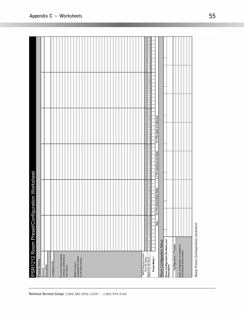
Technical Services Group: 1-800-283-5936 (USA) ~ 1-801-974-3760
55Appendix C ~ Worksheets
Pre
set S
etup
Des
crip
tio
n:
For
ext
ra la
rge
pres
ets,
cont
inue
com
man
ds in
next
col
umn.
Ref
er to
mac
ro
wor
kshe
et fo
r de
tails
on a
ll lis
ted
mac
ros.
13
57
911
1315
1719
13
57
911
1315
1719
13
57
911
1315
1719
13
57
911
1315
1719
13
57
911
1315
1719
13
57
911
1315
1719
Key
:
Roo
m C
onfig
urat
ion
Set
up
Eac
h co
nfig
urat
ion
is r
ecal
led
by
activ
atin
g its
list
ed p
rese
ts.
PS
R12
12 R
oom
Pre
set/C
onfig
urat
ion
Wor
kshe
et
Ro
om
Co
nfi
gu
rati
on
No
./Nam
e an
d
Des
crip
tio
n:
H =
Pin
Act
ive/
Hig
h S
tate
Pre
set
#
Co
mm
and
Lis
t:
Co
nfi
gu
rati
on
’s P
rese
ts:
DB
25 P
ort "
B"
Pin
#
DB
25 R
emot
e C
ontr
ol
Por
t "B
" S
etup
X =
Pin
sta
te is
irre
leva
nt
L =
Pin
Inac
tive
/Lo
w S
tate
Pre
set
Mas
k =
Roo
m P
rese
t C
onfi
gura
tion
wor
kshe
et

Technical Services Group: 1-800-283-5936 (USA) ~ 1-801-974-3760
56 Appendix C ~ Worksheets
Mac
ro S
etup
Des
crip
tio
n:
Des
crip
tio
n:
Des
crip
tio
n:
Des
crip
tio
n:
Des
crip
tio
n:
For
ext
ra la
rge
mac
ros,
cont
inue
com
man
ds in
next
col
umn.
Mac
ro #
/Nam
e
Co
mm
and
Lis
t:
Co
mm
and
Lis
t:
Co
mm
and
Lis
t:
Co
mm
and
Lis
t:
Co
mm
and
Lis
t:
PS
R12
12 M
acro
Wor
kshe
et
Mac
ro #
/Nam
e
Mac
ro #
/Nam
e
Mac
ro #
/Nam
e
Mac
ro #
/Nam
e
PSR
1212
Mac
ro w
orks
heet

Technical Services Group: 1-800-283-5936 (USA) ~ 1-801-974-3760
57
Appendix D: Glossary
Adaptive Ambient This portion of the mixer monitors the varying ambient noise level in the room and changes the
threshold level at which a microphone gates on.
Ambient Noise The existing room-level noise, such as that caused by ventilation systems, paper shuffling, and
background chatter.
Amplitude Plot A plot of amplitude (-18 to 18 dB) vs. frequency (20Hz to 20kHz) on a logarithmic scale.
Audio Processor A device that modifies an audio signal in response to certain requirements.
Automatic Gain Control (AGC) Automatically increases or decreases audio gain to maintain a consistent audio level.
Automatic Gating Automatically gates microphones on or off based on input levels and other parameters programmed
into the PSR1212.
Bandwidth The amount of spectrum space a signal occupies. For the PSR1212, it is adjustable from .05 to 5 octaves.
Changing the bandwidth setting affects the Q setting.
Chairman Override Provides gating priority for all microphones in the same gating group. When a chairman overide mic
in this group gates on, all mics in the group that are not chairman override enabled gate off.
Constant Directivity Horn Equalizer (CD Horn EQ) Horn drivers commonly used in arrays in arenas and auditoriums
have an inherent 6dB/octave high frequency rolloff. The PSR1212’s CD Horn EQ compensates for this characteristic.
Crossover A device that passes designated frequency segments of an audio signal to various loudspeaker elements in a
sound system.
Crossover, Bessel A crossover using a low-pass filter design characterized by a linear phase response. This results in a
constant time delay throughout the passband.
Crossover, Butterworth A crossover using a low-pass filter design characterized by a maximally flat magnitude
response. This results in no amplitude ripple in the passband.
Crossover, Linkwitz-Riley A fourth-order crossover consisting of a cascaded second-order Butterworth low-pass filter.
Offers a vast improvement over the Butterworth crossover and is the de facto standard for professional audio active
crossovers.
Decay Time The amount of time designated for a microphone to go from the On attenuation level to the Off level.
Digital Signal Processing (DSP) A method of signal enhancement which increases frequency response and dynamic
range while reducing noise.
Appendix D ~ Glossary

Technical Services Group: 1-800-283-5936 (USA) ~ 1-801-974-3760
58
Expansion Bus Consists of two RJ-45 connectors on the rear panel of the PSR1212. An expansion bus allows multiple
PSR1212s to be networked together using category five twisted-pair (10BaseT LAN) cable.
Filter A device that passes and blocks audio signals based on user-definable requirements of the system.
• All Pass A filter that provides only phase shift or phase delay without appreciably changing the magnitude
characteristic. The filter produces a flat amplitude response. It is useful for matching the delay of two processing
channels with different delays.
• High Pass A filter that passes high signal frequencies while attenuating low frequencies. The gain or loss
• High Shelving Provides boosting or attenuation of frequencies above a designated frequency. The transition
between the spectrum above and below the designated frequency occurs at a fixed 6dB/octave rate. The gain or
loss above the corner frequency is adjustable to +/- 15dB.
• Low Pass A filter that passes low frequencies while attenuating high frequencies.
• Low Shelving Provides boosting or attenuation of frequencies below a designated frequency. The transition
between the spectrum above and below the designated frequency occurs at a fixed 6dB/octave rate. The gain or
loss below the corner frequency is adjustable to +/- 15dB.
Filter Display A group of nodes plotted on a logarithmic scale. The filter display can be accessed through the Inputs 1–8,
From Processing, or To Processing windows.
First Mic Priority A condition in which a particular microphone is assigned gating priority over other microphones in a
PSR1212 system.
Gain The amount a signal is increased over a given reference, typically 0. Normally specified in dB (decibels).
Gate Threshold Adjust Specifies how much louder the microphone audio level must be above the ambient sound level
before a microphone gates on.
Gating Ratio The voice (input) level that must be reached before a microphone will gate on.
GPIO (general purpose input/output) The Control/Status Port B on the rear of the PSR1212 unit.
G-Ware Software The PSR1212’s setup and configuration software.
Hold Time The length of time that a microphone remains on after the voice (input) level drops below the gating
threshold. This prevents the microphone from gating off during brief pauses in speech.
Last Mic Mode Enables one of three microphone activation values: Last On, Mic 1, and Off.
Last On Mode Leaves the last-activated mic gated on until another microphone input gates on.
Macro A computer command consisting of a sequence of other commands.
Appendix D ~ Glossary

Technical Services Group: 1-800-283-5936 (USA) ~ 1-801-974-3760
59
Manual Gating Provides the ability to gate a microphone on or off manually.
Matrix Mixer A mixer that allows routing of any input or combination of inputs to an output or any combination of
outputs. In the case of the PSR1212, the matrix mixer permits level control at each cross point in the matrix.
Maximum Number of Mics/Filibuster Sets the maximum number of mics that can be gated on simultaneously.
Microphone Activation A condition in which a microphone is gated on.
Microphone Mixing A scenario where microphone inputs are mixed according to parameters such as gain levels and
gating priority.
Microphone 1 Mode Reverts mic assignment to a designated mic when all mics gate off.
Number of Open Mics (NOM) The number of microphones gated on at a given time.
Number of Open Mics/Constant Gain Mode Adjusts the output level based on the number of mics gated on and routed
to an output.
Off Attenuation The amount of level reduction a microphone is given when the microphone is not gated on.
PA Adaptive Mode The PSR1212 recognizes how much loudspeaker audio is picked up by the microphones and then
uses this level as the new ambient level when audio is present at the power amplifier. This prevents loudspeaker audio from
gating on a microphone, while still allowing people in the room to gate on microphones as they speak.
Paging Zone A subset of a paging system. Intended to isolate paging system outputs to specific geographical areas.
Parametric Equalizer (PEQ) A multi-band variable equalizer with control of gain, center frequency, and bandwidth. A
properly configured PEQ enables the PSR1212 to offset speaker or room acoustic deficiencies.
Phantom Power Power supplied by the host unit to power an auxiliary device, such as certain types of microphones. The
PSR1212 provides 24 volts of phantom power. This feature can be switched off for devices not requiring phantom power.
Phase Plot A plot of phase angle (-180 to 180 degrees) vs. frequency (20Hz to 20kHz) on a logarithmic scale. This plot
overlays the amplitude plot, and is generated only for the active filter display.
Pink Noise Acoustical noise whose amplitude is inversely proportional to the frequency within a defined frequency range.
Preset One of 32 configurable memories in the PSR1212. A preset can be programmed with a variety of routing, level,
gating, delay, filter, and equalizer settings to meet specific application requirements.
Q Quality factor It is the ratio of the center frequency divided by the bandwidth. Q reflects an inverse relationship to the
bandwidth, and adjusts from .02:1 to 40:1 on the PSR1212.
Appendix D ~ Glossary

Technical Services Group: 1-800-283-5936 (USA) ~ 1-801-974-3760
60
Reverberation Multiple reflections of sound waves in a room.
Signal Delay Used for introducing a delay to fill speakers in an audio system to provide balanced sound throughout the
room.
Table View Displays the numerical values of the filter parameters for all nodes of the active filter display.
Tone Generator A device for generating a reference tone for sound system calibration purposes.
White Noise Acoustical noise distributed evenly throughout a given frequency range.
Appendix D ~ Glossary

Technical Services Group: 1-800-283-5936 (USA) ~ 1-801-974-3760
61

ClearOne Communications ~ 1825 Research Way, Salt Lake City, UT 84119 ~ tel 1-800-945-7730 ~ fax 1-800-933-5107© 2002 ClearOne Communications, Inc.. All rights reserved. Information in this document subject to change without notice.